US5466912A - Convection oven - Google Patents
Convection ovenDownload PDFInfo
- Publication number
- US5466912A US5466912AUS03/097,492US9749293AUS5466912AUS 5466912 AUS5466912 AUS 5466912AUS 9749293 AUS9749293 AUS 9749293AUS 5466912 AUS5466912 AUS 5466912A
- Authority
- US
- United States
- Prior art keywords
- enclosure member
- housing
- air
- oven
- cooking chamber
- Prior art date
- Legal status (The legal status is an assumption and is not a legal conclusion. Google has not performed a legal analysis and makes no representation as to the accuracy of the status listed.)
- Expired - Fee Related
Links
Images


Classifications
- A—HUMAN NECESSITIES
- A47—FURNITURE; DOMESTIC ARTICLES OR APPLIANCES; COFFEE MILLS; SPICE MILLS; SUCTION CLEANERS IN GENERAL
- A47J—KITCHEN EQUIPMENT; COFFEE MILLS; SPICE MILLS; APPARATUS FOR MAKING BEVERAGES
- A47J37/00—Baking; Roasting; Grilling; Frying
- A47J37/06—Roasters; Grills; Sandwich grills
- A47J37/0623—Small-size cooking ovens, i.e. defining an at least partially closed cooking cavity
- A—HUMAN NECESSITIES
- A47—FURNITURE; DOMESTIC ARTICLES OR APPLIANCES; COFFEE MILLS; SPICE MILLS; SUCTION CLEANERS IN GENERAL
- A47J—KITCHEN EQUIPMENT; COFFEE MILLS; SPICE MILLS; APPARATUS FOR MAKING BEVERAGES
- A47J36/00—Parts, details or accessories of cooking-vessels
- A47J36/06—Lids or covers for cooking-vessels
- A47J36/12—Devices for holding lids in open position on the container
- A—HUMAN NECESSITIES
- A47—FURNITURE; DOMESTIC ARTICLES OR APPLIANCES; COFFEE MILLS; SPICE MILLS; SUCTION CLEANERS IN GENERAL
- A47J—KITCHEN EQUIPMENT; COFFEE MILLS; SPICE MILLS; APPARATUS FOR MAKING BEVERAGES
- A47J36/00—Parts, details or accessories of cooking-vessels
- A47J36/34—Supports for cooking-vessels
- A—HUMAN NECESSITIES
- A47—FURNITURE; DOMESTIC ARTICLES OR APPLIANCES; COFFEE MILLS; SPICE MILLS; SUCTION CLEANERS IN GENERAL
- A47J—KITCHEN EQUIPMENT; COFFEE MILLS; SPICE MILLS; APPARATUS FOR MAKING BEVERAGES
- A47J37/00—Baking; Roasting; Grilling; Frying
- A47J37/01—Vessels uniquely adapted for baking
- A47J37/015—Vessels uniquely adapted for baking electrically heated
- A—HUMAN NECESSITIES
- A47—FURNITURE; DOMESTIC ARTICLES OR APPLIANCES; COFFEE MILLS; SPICE MILLS; SUCTION CLEANERS IN GENERAL
- A47J—KITCHEN EQUIPMENT; COFFEE MILLS; SPICE MILLS; APPARATUS FOR MAKING BEVERAGES
- A47J37/00—Baking; Roasting; Grilling; Frying
- A47J37/06—Roasters; Grills; Sandwich grills
- A47J37/0623—Small-size cooking ovens, i.e. defining an at least partially closed cooking cavity
- A47J37/0629—Small-size cooking ovens, i.e. defining an at least partially closed cooking cavity with electric heating elements
- A47J37/0641—Small-size cooking ovens, i.e. defining an at least partially closed cooking cavity with electric heating elements with forced air circulation, e.g. air fryers
Definitions
- the present inventionrelates to a convection oven for cooking of food products.
- One embodiment of the inventionincludes a convection oven having a cooking chamber for holding the food to be cooked.
- the cooking chamberhas an upper enclosure member and a lower enclosure member.
- a housingis attached to the upper enclosure member.
- the housinghas a central portion and at least one arm extending outwardly from the central portion to beyond the outer edge of the upper enclosure member. Attached to the housing is a heater for heating air within the cooking chamber and an air-moving means for moving air within the cooking chamber.
- the housingis configured so that cool air flows from a peripheral portion of the arm into the central portion of the housing and then is expelled from the arm over the upper surface of the upper enclosure member.
- An alternative embodiment of the inventionincludes a convection oven designed to rest on a supporting surface such as a countertop.
- the ovenhas a frame including a base member which rests on the supporting surface and at least two upright members which extend upwardly from the base member.
- a cooking chamber for holding food to be cookedis removably supported by the frame and includes an upper enclosure member and a lower enclosure member.
- a housingis attached to the upper enclosure member. Attached to the housing is a heater for heating air within the cooking chamber and an air-moving means for moving air within the cooking chamber.
- a further embodiment of the inventionincludes a convection oven having a frame and designed to rest on a supporting surface such as a countertop.
- the ovenhas a cooking chamber for holding food to be cooked which includes a lower enclosure member for holding the food, and an upper enclosure member for covering the upper enclosure member.
- a housingis attached to the upper enclosure member.
- the holsterattaches to the frame of the oven and is configured to hold the upper enclosure and housing when they are separated from the lower enclosure member.
- One embodiment of the present inventionmay also include a holster for use in a convection oven having a frame and which is designed to rest on a supporting surface.
- the ovenfurther includes a cooking chamber which includes a lower enclosure member for holding the food and an upper enclosure member for covering the lower enclosure member.
- a housingis attached to the upper enclosure member.
- the holsteris attached to the frame of the oven and is configured to hold the housing and the upper enclosure member when they are separated from the lower enclosure member.
- the framehas a base member which rests on the supporting surface and an upright member extending upwardly from the base member.
- the cooking chamberhas an upper enclosure member and a lower enclosure member.
- a housingis attached to the upper enclosure member.
- the housinghas a central portion and an arm extending outwardly from the central portion. Attached to the housing is a heater for heating air within the cooking chamber and an air-moving means for moving air within the cooking chamber.
- a connecting meansconnects the housing to the frame such that the housing and upper enclosure member may be both separated from the frame and lower enclosure member by lifting the housing vertically and pivoted relative to the frame and lower enclosure member.
- the housing and upper enclosure membermay be pivoted between a first position wherein the upper enclosure member rests on the lower enclosure member and a second position wherein the upper enclosure member is separated from the lower enclosure member.
- the cooking chamberincludes an upper enclosure member and a lower enclosure member.
- the ovenincludes heating means for heating air within the cooking chamber and air-moving means for moving air within the cooking chamber.
- At least one extension ring for enlarging the size of the cooking chamberis included.
- the extension ringincludes a ring designed to be removably placed between the upper enclosure member and the lower enclosure member so as to increase the height of the cooking chamber, as well as handle means attached to the ring which can be gripped so as to selectively place the ring in between or remove the ring from between the upper enclosure member and the lower enclosure member.
- Yet another alternative embodiment of the present inventionincludes a convection oven having a cooking chamber for holding food to be cooked.
- the cooking chamberincludes an upper enclosure member and a lower enclosure member.
- the ovenincludes heating means for heating air within the cooking chamber and air-moving means for moving air within the cooking chamber.
- At least one extension ring for enlarging the size of the cooking chamberis included.
- the extension ringincludes a ring designed to be removably placed between the upper enclosure member and the lower enclosure member so as to increase the height of the cooking chamber.
- the ringis shaped so as to form a ledge for supporting a rack within the cooking chamber.
- the inventionalso may include an extension ring for enlarging the size of the cooking chamber of an oven.
- the extension ringincludes a ring designed to be removably placed between the upper enclosure member and the lower enclosure member so as to increase the height of the cooking chamber, and handle means attached to the ring which can be gripped so as to selectively place the ring in between or remove the ring from between the upper enclosure member and the lower enclosure member.
- the extension ringincludes a ring designed to be removably placed between the upper enclosure member and the lower enclosure member, with the ring being shaped so as to form a ledge for supporting a rack within the cooking chamber.
- Yet another alternative embodiment of the inventionmay include a convection oven having a cooking chamber for holding the food to be cooked.
- the cooking chamberhas an upper enclosure member and a lower enclosure member.
- a housing having a central portionis attached to the upper enclosure member. Attached to the housing is a heater for heating air within the cooking chamber and an axial-type hot-air fan for moving air in a substantially axial direction within the cooking chamber.
- the ovenmay also include a fan shroud surrounding the hot-air fan for providing an air duct around the periphery of the hot-air fan such that the radial component of the hot air is initially routed in a substantially axial direction off of the hot-air fan into the cooking chamber.
- a yet further embodiment of the inventionmay include a convection oven having a cooking chamber for holding the food to be cooked.
- the cooking chamberhas an upper enclosure member and a lower enclosure member.
- a housing having a central portion having a cooling fan for imparting cool air thereinis attached to the upper enclosure member. Attached to the housing is a heater for heating air within the cooking chamber and an air moving means for moving air within the cooking chamber.
- the ovenalso may include a thermostat adjacent to but isolated from the cool air in the central portion of the housing so that the thermostat more accurately reflects the temperature of the cooking chamber in the oven.
- FIG. 1is a perspective view of one preferred embodiment of a convection oven
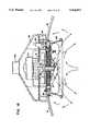
- FIG. 2is a vertical cross sectional view of the convection oven shown in FIG. 1;
- FIG. 3is a side view of the convection oven shown in FIG. 1, with part of one arm cut away to show the interior of the housing;
- FIG. 4is a bottom view of the end portion of an arm of the convection oven shown in FIG. 1.
- FIG. 5is a perspective view of a second preferred embodiment of a convection oven
- FIG. 6is a sectional view of the hinge of the convection oven shown in FIG. 5, shown in the closed position;
- FIG. 7is a sectional view of the hinge similar to FIG. 6, but showing the oven in the separated position;
- FIG. 8is a sectional view of the hinge similar to FIG. 6, but showing the oven in the open position;
- FIG. 9is a perspective view of the oven of FIG. 1, together with a preferred embodiment of an extension ring;
- FIG. 10is vertical cross-section of one end of the extension ring of FIG. 9;
- FIG. 11is a sectional view of the extension ring of FIG. 9, taken along lines 11--11 in FIG. 10;
- FIG. 12is a perspective view of a third preferred embodiment of a convection oven.
- FIG. 13is a vertical cross sectional view of the convection oven shown in FIG. 12;
- FIG. 14Ais a perspective view of the holster of the convection oven shown in FIG. 12;
- FIG. 14Bis a vertical cross sectional view of the convection oven shown in FIG. 12 showing an upper enclosure member and a housing resting in the holster of FIG. 14A.
- FIG. 15is a vertical cross sectional view of the convection oven shown in FIG. 12 with a preferred embodiment of a hot-air fan design, and thermostat configuration;
- FIG. 16is a vertical cross sectional view of the hot-air fan design and thermostat configuration of the convection oven shown in FIG. 12.
- FIGS. 1-4One preferred embodiment of a convection oven is shown in FIGS. 1-4.
- the convection oven 10includes a cooking chamber 12 removably supported by a frame 14.
- the cooking chamberis made up of a lower enclosure member 16 and an upper enclosure member 18.
- the upper and lower enclosure membersare preferably made out of heat resistant glass, such as PYREX.
- a cooking rack 19is preferably placed within the cooking chamber to support the food to be cooked.
- the lower enclosure memberhas a bottom wall 20 and a generally-cylindrical side wall 22.
- a ridge 24is formed along the upper edge of the side wall to support the upper enclosure member.
- the upper enclosure memberhas a centrally-located opening for receiving a heater and fan as will be hereinafter described.
- Frame 14is preferably made up of a base member 28 and at least two upright members 30.
- the base membermay be generally circular in shape, and is designed to rest on the supporting surface, such as a countertop.
- the upright membersare preferably located on diametrically opposed sides of the base member, and are made up of two riser portions 31 connected together by a connecting portion 33.
- the riser portions 31extend outwardly at the upper end thereof to form supporting surfaces 34.
- the lower enclosure member 16is configured to rest on the lower curved region 36 of the riser portions. Because of this arrangement, a small air space 38 is formed between the bottom wall 20 of the lower enclosure member and the base member 28. This air space helps to prevent the transfer of heat from the cooking chamber to the base member, so as to avoid excessive heating of the countertop. Alternatively, the air space may also be formed by placing a number of spacer members (not shown) between the bottom wall of the lower enclosure member and the base member.
- the design of the frameprovides passive cooling so as to keep the countertop cool. Specifically, air trapped in the region 42 between the connecting portion 33 of the upright members and the cooking chamber is heated by the cooking chamber. This hot air rises along the upright member. The rising air creates a suction effect, drawing cooler air into the region 42 from around the base member. This flow of air helps cool the base member and hence helps to keep the countertop cool.
- a number of cushioning members 40may be attached to the connecting portion 33 of the upright members. These cushioning members help provide support to the cooking chamber when it is held by the frame.
- Frame 14is preferably made of a thermoplastic material, such as by molding.
- the upright members of the embodiment of FIG. 1are preferably identical. As such, only two molds are required (one for the base member and one for the upright member). After molding, two of the upright members may be connected to a base member, for example using screws, to form the frame.
- a housing 44is attached to the upper enclosure member 18. Like the frame, the housing is preferably made out of a thermoplastic material. The housing is made up of a central portion 46 and two arms 48 which project outwardly from the central portion. The central portion 46 is generally circular in horizontal cross section. A handle 50 may be attached to the central portion of the housing.
- the arms 48project past the outer edge of the upper enclosure member 18.
- the armsare made up of a top wall 76, two side walls 77 and a middle wall 78 (see FIG. 2).
- the armsare configured so that the outer peripheral portion of the arms rest on the supporting surfaces 34 of the upright members. In this way, the housing 44 is supported and stabilized by the frame 14.
- the armsdefine two air channels.
- the upper channel 79is defined by the top wall 76, the two side walls 77, and the middle wall 78.
- An air inlet 80(FIG. 4) located at the outer end of the arms communicates with the upper channel 79.
- the lower channel 82is defined by the two side walls 77, the middle wall 78, and the upper surface of the upper enclosure member 18.
- a small space 81is present between the side walls 77 and the upper surface of the upper enclosure member. This space provides for the exit of cool air for cooling the upper surface of the upper enclosure member, as will be described below.
- a dividing member 53divides the interior space of the central portion 46 into an upper space 71 and a lower space 72.
- the dividing memberhas an opening 75 located in the center thereof which connects the upper space 71 and the lower space 72.
- a motor 52is mounted on the dividing member 53 and is located within the upper space 71.
- the motoris connected by a shaft 54 to a hot-air fan 56 located within the cooking chamber.
- the hot-air fan 56is preferably permanently attached to the shaft 54, such as by a hexnut.
- the heaterpreferably may be thermostatically regulated to maintain cooking temperatures ranging from 150 to 500+degrees F.
- the heatergenerally consists of heater coils 57 and heat spacer members 58 for separating the heater coils and for providing support thereto.
- the heat spacer members 58are preferably made of ceramic.
- a heater base 60is also provided for isolating the heater from the lower region 72, and is preferably made of metal.
- the heater coils 57are located at opposite ends of the heater base 60.
- the heater coils 57 and spacer members 58are mounted to the heater base 60, such as by screws.
- two insulating layers 63are provided on opposite sides of the heater coils 57, and are preferably made of Mica.
- the heater coilsare preferably an open coil, resistance wire type. Open heater coils are used in order to achieve the lowest possible surface watt density. With adequate air flow, such an element is capable of transferring maximum heat to the air stream via conduction, while operating in the "black" heat range. In order for other types of heating elements, such as tubular types, to give off the same wattage given the same space and airflow, the heater would glow. Such a high surface watt density would result in overheating of the motor, the food being cooked, and plastic parts through an excessive radiation of heat. In the present oven, the heater preferably operates in the "black" heat range or with only minimal glow. In addition, such an element would retain too much heat when the unit is shut off, causing additional over-temperature problems.
- the heater assemblyalso preferably incorporates an over-temperature device (not shown) capable of shutting off power to the heater should the thermostat fail.
- the housingis preferably attached to the upper enclosure member by sandwiching the inner rim 70 of the upper enclosure member between the dividing member 53 and the heater base 60.
- a cooling fan 74is located in the lower space 72.
- the cooling fanis preferably located on the same shaft as is hot-air fan 56, so that it is also rotated by motor 52.
- the upper air channel 79opens into the upper space 71.
- the side wall of the dividing member 53has a plurality of openings 84 located therein so that the lower air channel 82 communicates with the lower space 72.
- the above-described configuration of the housingprovides for a venting system for cooling the motor 52 as well as the upper enclosure member 18.
- rotation of the cooling fan 74causes cool air to be drawn in through the air inlet 80 and into the upper channel 79 of both arms 48. From there, the cool air enters the upper space of the central portion so as to cool the motor 52. The cool air is then drawn by the cooling fan down through the opening 75 into the lower space, and then expelled into the second channel. From there, the cool air is forced out through the small space 81 between the side walls of the arm and the upper enclosure member.
- the flow of cool airalso helps cool the housing itself which, being preferably made of plastic, cannot take the high temperatures produced in the heating chamber.
- the draw of air through the air inlet 80also increases the flow of air up through the region 42 between the upright members 30 and the lower enclosure member, thereby increasing the cooling of the base member.
- air inlets 86may also be preferable to include additional air inlets 86 in the housing. These air inlets are preferably located in the underside of handle 50 so as to minimize the chance that liquid, such as water used for cleaning, will accidentally enter the housing. The air inlets provide for additional flow of cooling air over the motor 52.
- the hot-air fan 56may be a radial-type fan which, unlike conventional devices, is placed in the top center of the cooking chamber.
- the hot-air fancreates two air circulations. The first air circulation is throughout the cooking chamber. In particular, hot air thrown off the fan travels horizontally parallel to the upper enclosure member until it is directed downward by the corner joining the upper and lower enclosure members. The air then travels downward until it is again deflected at the bottom wall of the lower enclosure member. The air is then simultaneously pushed and drawn by the blower across the top of and beneath the cooking rack. As the air approaches the center of the enclosure, it is drawn up into the open underside of the hot-air fan where it is then recirculated through the same pattern described above.
- the second air circulationpasses a small portion of air over the heated coils in the heater.
- the small air currentexits radially outwardly from the fan 56, reverses direction 180 degrees to be drawn in over the coil, then radially inwardly to the center of the heater, then downwardly into the center zone of the blade 56.
- This configurationprovides the following advantage: most particles are unable to make the abrupt 180 degree change in direction that the air drawn through the heater does. Therefore, the air traveling through the heater assembly is virtually free of contamination, while most particles are thrown off to the sides and bottom of the cooking chamber, where they can easily be cleaned away. As a result of the above, the heater does not accumulate food, oil or grease, thereby eliminating the need to clean the heater, extending heater element life and preventing smoke or fire hazard.
- a wire guard 62may be attached to the heater base 60 for protecting the hot-air fan 56. However, the wire guard does not substantially block the air flow created by the hot-air fan, so that hot air may be circulated within the cooking chamber in a substantially unrestricted manner.
- the velocity of the airis not constant within the chamber, since the heated air converges as it moves to the center of the cooking chamber and is drawn into the hot-air fan.
- the aircools as it contacts the food, but simultaneously accelerates as it converges on the center of the chamber. This change in velocity compensates for the dropping temperature by more effectively exchanging the heat remaining in the air.
- the resultis very uniform cooking from the outer edge to the center of the cooking rack.
- the velocity of the air in the ovenis preferably very high, in the range of 1000-4000 linear feet per minute in the vicinity of the food, with a range of 1200-2500 being particularly preferred.
- a thermostat 64is provided in the central portion 46 of the housing 44 which adjusts the current supplied to the heater so as to control the temperature within the cooking chamber.
- the thermostatis preferably an anticipator-type self-heating thermostat, such as one manufactured by Abundance Thermo Control Factory, Type A228, thereby more readily holding the temperature of the oven in a narrow range to prevent major fluctuations in the temperature which may adversely affect the cooking of the food.
- a timer/switch mechanism 66is also provided for turning the heater and motor on and for controlling the cooking time.
- a sensing mechanismmay be provided to provide shutdown of the unit in the case of overheating in the cooking chamber 12 and/or housing 44.
- a sensing mechanism(not shown) may also be included which shuts down the unit when the housing is removed from the frame with the switch 64 in the "on" position.
- FIGS. 15 and 16show another embodiment of a convection oven 10A.
- Much of the oven of FIGS. 15 and 16are preferably identical to the embodiment of FIGS. 1 and 2, and hence will not be described again in detail.
- the primary changes in this embodimentare the hot-air fan design and the thermostat configuration.
- hot-air fan 56'is an axial-type fan.
- a fan shroud 62'replaces the wire guard 62.
- the fan shroud 62'has an opening in the center to provide for the preferred air flow as described below.
- a washer 59is also attached to the shaft 54 directly above the fan shroud 62' for providing a safety mechanism to ensure that the blades of the hot-air fan 56' are out of reach of a user's fingers.
- wire guard 62neither the fan shroud 62' nor the washer 59 substantially blocks the air flow created by the hot-air fan, so that the hot air may be circulated within the cooking chamber in a substantially unrestricted manner.
- hot-air fan 56'also imparts a radial component of velocity on the air.
- fan shroud 62'provides a substantially vertical air duct around the periphery of the hot-air fan 56' to minimize this effect. As a result, less heat is lost to the side walls of the lower enclosure member, and more hot air is initially directed at the food itself.
- hot-air fan 56'also on its own imparts an axial component of velocity on the air. Therefore, the axial fan and fan shroud configuration provides an additional advantage over the radial-type hot-air fan by directing significantly more air in a downward direction, thereby more directly heating the food as well as creating a low pressure region around the shaft 54 in the lower space 72. This in turn pulls significantly more air through the heater coils 57, and thus more efficiently removes heat from the heater coils 57. As a result, the temperature by the heater coils 57 is lower, making the heater coils last much longer.
- thermostat 64'is contained within a thermostat chamber 65 adjacent the cooling fan 74 and the lower space 72.
- the thermostat chamber 65has an opening 61 in the bottom so that hot air from the cooking chamber may be directed therein (see FIG. 16).
- the thermostat chamberisolates the thermostat 64' from the lower space 72 and the cooling fan 74, and thus prevents cool air from the lower space 72 from affecting thermostat 64'. This configuration allows the oven to provide a more accurate reading.
- the convection ovens described aboveare used by first lifting up on the housing 44 so as to remove the upper enclosure member 18 from the lower enclosure member 16. Food pieces such as potatoes, bakery goods, pizzas and the like may be placed on the rack 19. The housing 44 is then once again placed on the frame 14, so that the upper enclosure member 18 again rests on the lower enclosure member 16. The thermostat is then activated turning the heating and the motor on. With the hot-air fan rotating, air is moved within the cooking chamber. Air is circulated over the heater coils 57, thereby providing heat to the cooking chamber 12. The temperature will typically be in the range of 150-500 degrees F.
- the outer edges of the arms 48extend below the lower surface of the upper enclosure member 18. This is a useful feature because, when the housing 44 and upper enclosure member 18 are lifted off the frame 14 and placed on the countertop, the hot upper enclosure member 18 does not come into direct contact with the countertop. Hence, the chances of burning the countertop are reduced.
- FIG. 5shows yet another embodiment of a convection oven 10B.
- Much of the oven of FIG. 5is preferably identical to that of FIG. 1, and hence will not be described again in detail. It can be appreciated, however, that either or both of the hot-air fan designs and thermostat configurations previously described herein may be incorporated in this embodiment.
- the primary change in this embodimentis that the convection oven has only one upright member 30 and arm 48 as described in connection with the first embodiment.
- the other upright member 30' and arm 48'have been modified as described below.
- the upright member 30' and arm 48'are connected together by a connecting mechanism 90.
- This connecting mechanismacts as a "passive hinge" which allows the housing and upper enclosure member to be either lifted off and removed from the frame and lower enclosure member, or simply tilted back so as provide access to the interior of the cooking chamber.
- the connecting mechanismincludes two hubs 92 attached to the upright member 30' and two engagement members 94 attached to the arm 48'.
- the hubs 92are generally circular in vertical cross-section and have an opening 93 in the upper surface thereof.
- Two stop surfaces 95are preferably located within the hubs.
- the engagement membersmay be generally triangular in shape, and are designed to fit through the opening 93 and rotate snugly within the hubs 92.
- Connecting mechanism 90is designed to allow the convection oven to function in three positions, as shown in FIGS. 6-8.
- the ovenis shown in the closed position in FIG. 6.
- the engagement members 94are located within the hubs 92.
- the arms 48 and 48'are resting on the upright members 30 and 30', respectively.
- the upper enclosure member 18is resting on the lower enclosure member 16.
- the housingmay be lifted vertically to the separated position shown in FIG. 7.
- the engagement members 94pass through the openings 93 so as to disconnect the housing 44 from the frame 14.
- the upper enclosure membercan be completely removed from the lower enclosure member, so as to provide access to the interior of the cooking chamber.
- the housingmay be rotated from the closed position of FIG. 6 to the open position of FIG. 8.
- the engagement members 94rotate within the hubs 92.
- the engagement memberscontact the stop surfaces 95, so as to prevent rotation of the housing past the open position.
- the upper enclosure membercan simply be tipped back so as to provide access to the interior of the cooking chamber.
- the engagement members 94are attached to the arm 48' and the hubs 92 are attached to the upright member 30', this configuration can be reversed.
- the engagement membersmay be formed on the upper portion of upright members, with the hubs mounted on the end of arm 30'.
- the openings 93are positioned in the lower surface, rather than the upper surface, of the hubs.
- the engagement membersare still preferably triangular in shape, but would taper upwardly, instead of downwardly as shown in FIG. 6.
- the hubs 92are preferably well spaced apart on opposite sides of the upright member 30'.
- the upper enclosure member and motor assemblyare relatively heavy, and can exert substantial sideways torque when the housing is moved to the open position. By spacing the hubs wide apart, the connecting mechanism is better able to withstand this torque created when the oven is opened.
- the other primary difference between the embodiment of FIG. 5 and the embodiment of FIG. 1is that the mechanisms for controlling the oven temperature and fan speed are located on the upright member 30'.
- a control panel 96is attached to the front of the upright member 30'.
- the control panelpreferably has a digital display panel 97 and a plurality of buttons 98 for controlling the cooking temperature and programming cooking times.
- a base extension 99extends outwardly from the upright member 30'. The purpose of this base extension is to provide extra stability to the oven when the housing and upper enclosure member are tilted to the open position.
- FIGS. 9-11shows a preferred embodiment of an extension ring 101 used to enlarge the cooking chamber of an oven, such as that of FIG. 1.
- the extension ringincludes a ring 103 and two handles or spacers 105.
- the ringis designed to removably fit in between the lower enclosure member 16 and upper enclosure member 18, while the spacers fit between upright members 30 and arms 48.
- Ring 103is preferably made of metal. As better seen in FIG. 10, preferred ring 103 is not of uniform diameter.
- a ridge 107may be formed at the upper edge of the ring. This ridge is similar to the ridge 24 formed at the top of the lower enclosure member, and is designed to receive the upper enclosure member.
- the lower edge 109 of the ringpreferably is dimensioned to rest on the ridge 24.
- a ledge 111may also be formed in the middle of the ring 103. This ledge is designed to support a further rack (not shown) which may be placed within the enlarged cooking chamber so as to provide an additional level for cooking. It is to be noted that an extension ring configured with a ledge or other protrusion for removably supporting a cooking rack need not employ spacers or handles 105, although such handles are preferred.
- the spacers 105are preferably made up of plastic.
- the spacersmay include two side walls 113, a top wall 115, and a back wall 117.
- the top wall 115preferably has the same general shape as the supporting surface 34 of the upright members 30, and hence is configured to support the arms 48.
- the lower edge of the spacershas the same general shape as the lower end of arms 48, and hence is configured to rest on supporting surface 34.
- the back wall 117preferably has a recessed portion 119.
- the recessed portiondefines a lifting surface 120 which provides for a convenient location to grip the extension ring when placing the extension ring on or removing the extension ring from the convection oven.
- the spacers 105serve as a handle means for the ring 103. It will be recognized that many other configurations of spacers or handles 105 are possible; for example, in an oven configuration where upright members 30 and arms 48 are not employed, handles 105 could have virtually any configuration.
- the spacerspreferably have a plurality of bosses 121 projecting inwardly from the back wall 117. These bosses have holes in them for receiving screws or rivets used to connect the ring 103 and the spacers 105 together.
- the bosses 121preferably extend slightly past the edge of side walls 113 and top wall 115 so that a small space 123 is maintained between the walls of the spacers and the ring. This space improves air circulation and helps to prevent heat damage to the plastic spacers.
- FIGS. 12 and 13show another embodiment of a convection oven 10C.
- Much of the oven of FIGS. 12 and 13are preferably identical to the embodiment of FIGS. 1 and 2, and hence will not be described again in detail. Again, it can be appreciated that either or both of the hot-air fan designs and thermostat configurations previously described herein may be incorporated in this embodiment.
- This embodimentincludes a control panel 96 like that shown in the embodiment of FIG. 5. However, unlike the embodiment shown in FIG. 5, this embodiment still includes two upright members 30 and two arms 48.
- the convection oven of FIGS. 12 and 13includes a holster 51 which may be attached to the frame 14 of the oven for holding the upper enclosure member 18 and housing 44 against the side of the oven when they are separated from the lower enclosure member 16.
- a holster 51which may be attached to the frame 14 of the oven for holding the upper enclosure member 18 and housing 44 against the side of the oven when they are separated from the lower enclosure member 16.
- the upper enclosure member 18 and the housing 44need not take up valuable countertop space.
- the holster 51the upper enclosure member 18 is kept off of the countertop, thus reducing the amount of clean up after cooking.
- the holster 51has a substantially vertical wall 100 and a substantially flat, substantially horizontal base 104 attached to the substantially vertical wall 100.
- the substantially vertical wall 104preferably includes two side walls 102 which define a cut-out portion for receiving the upper enclosure member 18 and housing 44 on edge.
- a portion 106 of the holster base 104attaches to the frame 14 of the oven.
- the portion 106is attached to the underside of the base member 28 of the frame 14, such as by screws.
- FIG. 14Bshows the upper enclosure member 18 and the housing 44 in its resting position in the holster 51. Due to the low focus of weight of the holster 51, it provides support to the upper enclosure member 18 and housing 44 when they are placed therein, and ensures their stability.
Landscapes
- Engineering & Computer Science (AREA)
- Food Science & Technology (AREA)
- Electric Stoves And Ranges (AREA)
- Baking, Grill, Roasting (AREA)
Abstract
Description
Claims (91)
Priority Applications (4)
| Application Number | Priority Date | Filing Date | Title |
|---|---|---|---|
| US03/097,492US5466912A (en) | 1993-04-13 | 1993-07-27 | Convection oven |
| CA002160490ACA2160490A1 (en) | 1993-04-13 | 1994-04-06 | Convection oven |
| EP94914060AEP0693894A1 (en) | 1993-04-13 | 1994-04-06 | Convection oven |
| PCT/US1994/003783WO1994023627A2 (en) | 1993-04-13 | 1994-04-06 | Convection oven |
Applications Claiming Priority (3)
| Application Number | Priority Date | Filing Date | Title |
|---|---|---|---|
| US4283993A | 1993-04-13 | 1993-04-13 | |
| US5091893A | 1993-04-27 | 1993-04-27 | |
| US03/097,492US5466912A (en) | 1993-04-13 | 1993-07-27 | Convection oven |
Publications (1)
| Publication Number | Publication Date |
|---|---|
| US5466912Atrue US5466912A (en) | 1995-11-14 |
Family
ID=27366221
Family Applications (1)
| Application Number | Title | Priority Date | Filing Date |
|---|---|---|---|
| US03/097,492Expired - Fee RelatedUS5466912A (en) | 1993-04-13 | 1993-07-27 | Convection oven |
Country Status (4)
| Country | Link |
|---|---|
| US (1) | US5466912A (en) |
| EP (1) | EP0693894A1 (en) |
| CA (1) | CA2160490A1 (en) |
| WO (1) | WO1994023627A2 (en) |
Cited By (50)
| Publication number | Priority date | Publication date | Assignee | Title |
|---|---|---|---|---|
| US5676044A (en)* | 1996-01-03 | 1997-10-14 | Lara, Jr.; George A. | Rotary air impingement oven |
| US5701388A (en)* | 1994-12-22 | 1997-12-23 | Kohler Co. | Combined heater and pump |
| US5967135A (en)* | 1998-06-17 | 1999-10-19 | Shariat; Saeed | Cooking device with convection powered fan and water reservoir |
| US6198076B1 (en) | 1999-11-17 | 2001-03-06 | National Presto Industries, Inc. | Convection oven |
| US6201217B1 (en)* | 1999-04-12 | 2001-03-13 | Heartware Home Products, Inc. | Counter-top electric cooker |
| WO2003026469A3 (en)* | 2001-09-28 | 2003-06-19 | Hearthware Home Products Inc | Counter-top electric cooker having a safety shut-off switch |
| US20030146201A1 (en)* | 2002-02-05 | 2003-08-07 | Smith Charles Ray | Oven and methods for operating same |
| US20030146205A1 (en)* | 2002-02-05 | 2003-08-07 | Rael Jennifer Elizabeth | Multi rack oven and methods for operating same |
| US6651646B1 (en) | 2002-07-03 | 2003-11-25 | California Acrylic Industries | Barbecue grill with recirculation fan |
| US20040089648A1 (en)* | 2002-07-29 | 2004-05-13 | Griffey Dean J. | Open coil heater element convection system for convection ovens and the like |
| US6747250B1 (en) | 2003-01-10 | 2004-06-08 | Morning Electronics Co. Ltd. | Counter-top electric oven |
| KR100506748B1 (en)* | 2002-09-18 | 2005-08-05 | 임재강 | electric cooker |
| US6936795B1 (en)* | 2004-04-14 | 2005-08-30 | Hearthware Home Products, Inc. | Method and apparatus for securing a power head on an electric cooker |
| US20060006163A1 (en)* | 2002-08-30 | 2006-01-12 | Wolf Appliance Company, Llc | Convection oven with forced airflow circulation zones |
| US20060213497A1 (en)* | 2005-03-22 | 2006-09-28 | Orozco Miguel D J | Barbeque grill |
| US20080163764A1 (en)* | 2004-06-08 | 2008-07-10 | Seb S.A. | Air Flow Cooking Device |
| US20080213447A1 (en)* | 2004-06-08 | 2008-09-04 | Seb S.A. | Fryer with Automatic Coating of Fat |
| US20090134140A1 (en)* | 2006-06-16 | 2009-05-28 | Kavaring Cooking Systems B.V. | Apparatus for preparing food and air guide member therefor |
| US20090229476A1 (en)* | 2008-03-13 | 2009-09-17 | Mark Bedard | Portable cooking device |
| US20090321410A1 (en)* | 2007-11-30 | 2009-12-31 | Ibc-Hearthware, Inc. | System and method for a programmable counter-top electric dehydrator |
| US20100089248A1 (en)* | 2008-10-10 | 2010-04-15 | Edward Michael Jones | Convection grill |
| US20100199859A1 (en)* | 2009-02-12 | 2010-08-12 | Kuei-Tang Chang | Roasting oven structure and heightened structural improvement of its oven wall |
| US7964824B2 (en) | 2007-11-30 | 2011-06-21 | Ibc-Hearthware, Inc. | System, method and computer program product for programmable counter-top electric oven |
| USD643244S1 (en)* | 2010-10-15 | 2011-08-16 | Dart Industries Inc. | Covered baking container |
| USD651456S1 (en)* | 2010-03-12 | 2012-01-03 | Ibc-Hearthware, Inc. | Portable countertop electric oven |
| USD651850S1 (en)* | 2010-03-12 | 2012-01-10 | Ibc-Hearthware, Inc. | Cooking housing for a portable countertop electric oven |
| US8330083B2 (en) | 2007-11-30 | 2012-12-11 | Hearthware, Inc. | Portable countertop electric oven |
| USD693643S1 (en)* | 2010-03-12 | 2013-11-19 | Hearthware Inc. | Power head for a portable countertop electric oven |
| US20140021191A1 (en)* | 2007-11-30 | 2014-01-23 | Hearthware, Inc. | System and Method for a Programmable Counter-top Electric Oven and Dehydrator |
| US20140224132A1 (en)* | 2013-02-13 | 2014-08-14 | Tall & Stout Industrial Corp. | Dry fryer with stirring function and heating cover thereof |
| US8957350B1 (en) | 2013-10-08 | 2015-02-17 | S&S X-Ray Products, Inc. | Medical device for preparing thermoplastic material |
| USD728301S1 (en)* | 2013-09-25 | 2015-05-05 | Hearthmark, Llc | Automatic canning appliance |
| EP2807960A4 (en)* | 2012-06-11 | 2015-10-14 | Zejv Chen | Cooking pot having rotating and rolling basket |
| USD743201S1 (en)* | 2014-08-08 | 2015-11-17 | E. Mishan & Sons, Inc. | Air fryer |
| US20160051086A1 (en)* | 2013-04-24 | 2016-02-25 | De' Longhi Appliances S.R.L. | Cooking machine |
| US20160338547A1 (en)* | 2010-12-21 | 2016-11-24 | Sanandan Sudhir | Cooking Apparatus |
| EP3009054A4 (en)* | 2013-06-10 | 2017-03-29 | Mai, Tianhong | Air heating type cooking pan |
| IT201600097483A1 (en)* | 2016-09-28 | 2018-03-28 | De Longhi Appliances Srl | AUTONOMOUS APPARATUS FOR COOKING FOOD AND ITS METHOD |
| US10307018B2 (en)* | 2010-09-10 | 2019-06-04 | Koninklijke Philips N.V. | Apparatus for preparing food |
| US20190254476A1 (en)* | 2019-02-25 | 2019-08-22 | Sharkninja Operating Llc | Cooking device and components thereof |
| US10427116B2 (en)* | 2013-03-01 | 2019-10-01 | Whirlpool Corporation | Stirring wand |
| US20190374064A1 (en)* | 2017-08-09 | 2019-12-12 | Sharkninja Operating Llc | Cooking device and components thereof |
| US10881244B2 (en) | 2016-08-08 | 2021-01-05 | William C. Stumphauzer | Lid assembly for stove top convection cooking |
| US11045047B2 (en) | 2017-11-10 | 2021-06-29 | Ron's Enterprises, Inc. | Variable capacity oven |
| US11134808B2 (en) | 2020-03-30 | 2021-10-05 | Sharkninja Operating Llc | Cooking device and components thereof |
| WO2022062790A1 (en)* | 2020-09-22 | 2022-03-31 | 佛山市顺德区美的电热电器制造有限公司 | Air frying container and cooking appliance |
| US11297981B2 (en)* | 2010-12-21 | 2022-04-12 | Sanandan Sudhir | Multifunctional food processor |
| CN114521808A (en)* | 2020-11-23 | 2022-05-24 | 广东美的生活电器制造有限公司 | Cooking equipment |
| US20230130495A1 (en)* | 2021-10-21 | 2023-04-27 | Seb S.A. | Apparatus For Cooking With Ventilated Hot Air And/Or For Grilling Food |
| US11751710B2 (en) | 2019-02-25 | 2023-09-12 | Sharkninja Operating Llc | Guard for cooking system |
Families Citing this family (1)
| Publication number | Priority date | Publication date | Assignee | Title |
|---|---|---|---|---|
| RU2678373C1 (en) | 2013-12-13 | 2019-01-28 | Конинклейке Филипс Н.В. | Air guide member in air-based fryer |
Citations (88)
| Publication number | Priority date | Publication date | Assignee | Title |
|---|---|---|---|---|
| US1986088A (en)* | 1932-11-11 | 1935-01-01 | Wild Barfield Electr Furnaces | Electric oven |
| US2408331A (en)* | 1943-04-12 | 1946-09-24 | Mills Engineering Company | Air-conditioned electric cooking oven |
| FR934357A (en)* | 1945-10-08 | 1948-05-20 | Improvements to cooking processes and apparatus | |
| US2523796A (en)* | 1948-03-04 | 1950-09-26 | Gen Electric | Portable roaster and broiler |
| US2708709A (en)* | 1954-03-16 | 1955-05-17 | Gen Motors Corp | Domestic appliance |
| US2898437A (en)* | 1956-06-06 | 1959-08-04 | Gen Electric | Combination electric cooking appliance |
| US2949524A (en)* | 1957-07-17 | 1960-08-16 | Scarioni Romeo | Baking furnace |
| US2957067A (en)* | 1958-08-14 | 1960-10-18 | Philco Corp | Appliance units |
| US3074179A (en)* | 1960-08-26 | 1963-01-22 | Faustel Inc | Web dryer |
| US3077530A (en)* | 1959-05-06 | 1963-02-12 | Gen Electric | Cooking appliance |
| US3168642A (en)* | 1963-01-24 | 1965-02-02 | Market Forge Company | Electrically heated forced air circulation oven |
| US3239651A (en)* | 1963-08-21 | 1966-03-08 | Ekco Products Company | Heating unit |
| US3266559A (en)* | 1963-02-15 | 1966-08-16 | American Mach & Foundry | Method of drying foamed materials, e. g. foods |
| US3414708A (en)* | 1965-10-22 | 1968-12-03 | Malleable Iron Range Company | Forced convection oven |
| US3514576A (en)* | 1968-06-24 | 1970-05-26 | Hirst Microwave Heating Ltd | Combined microwave and hot air oven |
| US3529556A (en)* | 1968-11-20 | 1970-09-22 | Jack E Barnes | Barbecue forge |
| US3529582A (en)* | 1968-12-09 | 1970-09-22 | Gen Electric | Self-cleaning forced convection oven |
| US3586516A (en)* | 1969-04-18 | 1971-06-22 | Fred C Smith | Meat defrosting apparatus |
| US3692968A (en)* | 1970-04-06 | 1972-09-19 | Sanyo Electric Co | Electronic oven |
| US3759241A (en)* | 1971-12-16 | 1973-09-18 | Koninkl Fabriek Inventum Nv | Oven |
| US3770408A (en)* | 1971-11-15 | 1973-11-06 | Midland Ross Corp | Annealing lehr |
| US3817346A (en)* | 1972-08-21 | 1974-06-18 | D Wehmeyer | Mobile scaffolding |
| US3820524A (en)* | 1970-06-08 | 1974-06-28 | R Buckell | Cooking ovens |
| US3821454A (en)* | 1971-12-15 | 1974-06-28 | Leon Lobel | Method of ageing meat |
| US3828760A (en)* | 1973-05-23 | 1974-08-13 | Lca Corp | Oven |
| US3883671A (en)* | 1973-05-07 | 1975-05-13 | American Potato Co | Wetting the surfaces of dough pieces prior to frying to eliminate blistering |
| US3884213A (en)* | 1973-03-30 | 1975-05-20 | Donald P Smith | Cooking apparatus |
| DE2412835A1 (en)* | 1974-03-16 | 1975-09-18 | Vogt Hans Dr H C | Domestic hot-air cooking appliance with two insulated containers - has mechanical and electrical parts in top supplying hot air below |
| US3926106A (en)* | 1972-06-15 | 1975-12-16 | Burger Eisenwerke Ag | Food-treatment apparatus with circulated hot combustion gas |
| GB1429482A (en)* | 1972-01-13 | 1976-03-24 | Unilever Ltd | Storing and displaying a chilled temperature food pack |
| US3962962A (en)* | 1974-10-03 | 1976-06-15 | Anderson William G | System and hot cabinet server |
| DE7442343U (en)* | 1974-12-19 | 1976-07-01 | Bosch-Siemens Hausgeraete Gmbh, 7000 Stuttgart | Fermentation tanks for baking, roasting and grilling, especially baking and roasting tubes with pyrolytic self-cleaning |
| US3978843A (en)* | 1974-01-09 | 1976-09-07 | Buderus'sche Eisenwerke Aktiengesellschaft | Food cooking oven with controlled air circulation |
| US4010349A (en)* | 1975-02-27 | 1977-03-01 | Lincoln Manufacturing Company, Inc. | Proofing cabinet |
| US4010341A (en)* | 1972-11-13 | 1977-03-01 | Ifo Kampri Ab | Hot air oven |
| US4039776A (en)* | 1975-09-19 | 1977-08-02 | National Equipment Corporation | Closed passage heat holding apparatus |
| US4051347A (en)* | 1972-11-24 | 1977-09-27 | Siemens Aktiengesellschaft | Method and apparatus for baking food in a closed cooking space in which heated air is circulated |
| US4071738A (en)* | 1976-01-06 | 1978-01-31 | Jenn Air Corporation | Ventilated range with convertible radiant convection oven |
| DE2632000A1 (en)* | 1976-07-16 | 1978-03-02 | Johannes Dipl Ing Theermann | Container for keeping food hot - has thermostatically controlled electric heating elements in lid of dish |
| US4092390A (en)* | 1973-02-23 | 1978-05-30 | Mulvany Jr R F | System and method for heating and forming thermoplastic material |
| US4112916A (en)* | 1976-08-12 | 1978-09-12 | Raul Guibert | Hot air oven for food-loaded cartridges |
| FR2390928A1 (en)* | 1977-05-17 | 1978-12-15 | Wittig Jacques | Commercial rotisserie and oven - has support discs for dishes rotating in hot chamber with inbuilt turbines for air circulation |
| US4132216A (en)* | 1977-03-11 | 1979-01-02 | Raul Guibert | Two-zone hot air oven for food-loaded cartridges |
| US4133336A (en)* | 1977-09-29 | 1979-01-09 | Smith Alva T | Ventilated stove |
| US4154861A (en)* | 1976-05-19 | 1979-05-15 | Smith Donald P | Heat treatment of food products |
| GB2007515A (en)* | 1977-10-26 | 1979-05-23 | Villamos Berendezes Es Keszule | Air Circulating and Mixing Apparatus for Cooking Pots |
| FR2409736A1 (en)* | 1977-11-25 | 1979-06-22 | Fischer Karl | Food processing unit with hot air circulation - has heating elements and fan mounted inside processing chamber itself for compact design |
| US4173215A (en)* | 1977-12-05 | 1979-11-06 | Mscan Metal Canada Limitee | Apparatus for steaming foods |
| US4208572A (en)* | 1977-05-20 | 1980-06-17 | Despatch Industries, Inc. | Oven |
| US4210072A (en)* | 1978-02-02 | 1980-07-01 | Ivano Pedrini | Portable cooking apparatus suitable as an oven or as a grill |
| US4226178A (en)* | 1978-02-04 | 1980-10-07 | Rowenta-Werke, Gmbh | Hot-air grills |
| US4286456A (en)* | 1978-11-22 | 1981-09-01 | Carlo Erba Strumentazione S.P.A. | Gas chromatographic chamber |
| US4295034A (en)* | 1977-12-06 | 1981-10-13 | Grossag Gmbh | Hot air grill |
| JPS5741529A (en)* | 1980-08-20 | 1982-03-08 | Matsushita Electric Ind Co Ltd | Heating apparatus |
| US4327279A (en)* | 1979-11-27 | 1982-04-27 | Sunsetl, Ltd. | Counter-top reheating unit for packaged pre-cooked meals |
| US4350874A (en)* | 1980-02-25 | 1982-09-21 | Imanishi Flexible Tube Mfg. Co., Ltd. | Hot air supply type electric oven |
| JPS57174624A (en)* | 1981-04-20 | 1982-10-27 | Matsushita Seiko Co Ltd | Heating device |
| US4374319A (en)* | 1979-11-27 | 1983-02-15 | Sunset Ltd. | Counter-top oven |
| US4374318A (en)* | 1980-09-08 | 1983-02-15 | Umc Industries, Inc. | Apparatus for heating food, such as french fried potatoes |
| US4375184A (en)* | 1980-09-08 | 1983-03-01 | Umc Industries, Inc. | Apparatus for heating foods, such as french fried potatoes |
| US4420679A (en)* | 1982-02-26 | 1983-12-13 | Delta Associates, Inc. | Gas chromatographic oven using symmetrical flow of preheated - premixed ambient air |
| US4426923A (en)* | 1982-06-18 | 1984-01-24 | Takashi Ohata | Storage device for processed foods |
| US4439459A (en)* | 1982-03-08 | 1984-03-27 | Swartley John S | Convection food heating |
| CH643129A5 (en)* | 1978-07-18 | 1984-05-30 | Reese Werner Reese Technik Ing | Electric multipurpose kitchen heating appliance with upper and lower heating |
| US4455924A (en)* | 1982-09-30 | 1984-06-26 | Alco Standard Corporation | Oven for cooking and flavoring meat products |
| US4460822A (en)* | 1982-02-01 | 1984-07-17 | Market Forge, Div. Of Beatrice Foods Co. | Pressureless steam cooker |
| US4467777A (en)* | 1980-07-10 | 1984-08-28 | Niro Plan Ag | Gas or electrically heated convection air oven for baking foods |
| US4471000A (en)* | 1981-05-22 | 1984-09-11 | Wolverine Corporation | Method of cooking foods |
| US4477706A (en)* | 1982-07-19 | 1984-10-16 | Control Data Corporation | Combination microwave/convection and broiling oven |
| US4481396A (en)* | 1980-04-22 | 1984-11-06 | Sharp Kabushiki Kaisha | Combination microwave and convection oven |
| US4484064A (en)* | 1982-07-26 | 1984-11-20 | Murray Jerome L | Coffee roaster |
| US4484063A (en)* | 1980-02-25 | 1984-11-20 | Rival Manufacturing Company | Convection oven |
| US4491065A (en)* | 1982-05-06 | 1985-01-01 | Larry Poulson | Food heating apparatus |
| US4503760A (en)* | 1981-10-05 | 1985-03-12 | Omega Air Flow-21, Ltd. | Forced convection oven |
| US4506598A (en)* | 1981-10-31 | 1985-03-26 | Siegfried Meister | Apparatus for the heating of foodstuffs by means of a steam-air mixture |
| US4509412A (en)* | 1983-03-04 | 1985-04-09 | Rival Manufacturing Company | Food steaming device |
| US4516012A (en)* | 1981-06-22 | 1985-05-07 | G. S. Blodgett Co., Inc. | Dual flow heating apparatus |
| US4561348A (en)* | 1983-09-07 | 1985-12-31 | Eurogrill B.V. | Apparatus for grilling meat or the like |
| US4591698A (en)* | 1984-03-12 | 1986-05-27 | Chang Hong Tsuan | Electric dual and quick cooking utensil |
| US4749581A (en)* | 1985-09-03 | 1988-06-07 | Lincoln Foodservice Products, Inc. | Method for baking a food product |
| US4757800A (en)* | 1987-01-14 | 1988-07-19 | Lincoln Foodservice Products, Inc. | Air flow system for a low profile impingement oven |
| US4781169A (en)* | 1987-04-14 | 1988-11-01 | Lincoln Foodservice Products, Inc. | Oven with radiant panel |
| US4818550A (en)* | 1988-01-11 | 1989-04-04 | Robert H. Clark, Iii | Apparatus and process for marinating foodstuffs |
| US4817509A (en)* | 1987-02-17 | 1989-04-04 | Alternative Pioneering Systems Inc. | Air Fryer |
| US5165138A (en)* | 1991-08-19 | 1992-11-24 | Charles Garabedian | Cleaning device |
| US5165328A (en)* | 1987-02-17 | 1992-11-24 | Alternative Pioneering Systems, Inc. | Expandable countertop oven |
| US5205274A (en)* | 1989-09-22 | 1993-04-27 | Patentsmith Ii, Inc. | Turntable convection oven |
| US5245159A (en)* | 1991-10-23 | 1993-09-14 | Chang Kwei T | Transparent housing for an electric heat convection stove |
Family Cites Families (3)
| Publication number | Priority date | Publication date | Assignee | Title |
|---|---|---|---|---|
| DE2753827A1 (en)* | 1977-12-02 | 1979-06-07 | Bosch Siemens Hausgeraete | Table top food preparation unit using hot air - has lid and stand allowing removal of cooking pot for serving at table |
| US4397875A (en)* | 1980-09-08 | 1983-08-09 | Umc Industries, Inc. | Method of heating food |
| GB2102561B (en)* | 1981-07-25 | 1984-10-31 | Imarflex Mfg | Culinary heating apparatus |
- 1993
- 1993-07-27USUS03/097,492patent/US5466912A/ennot_activeExpired - Fee Related
- 1994
- 1994-04-06EPEP94914060Apatent/EP0693894A1/ennot_activeWithdrawn
- 1994-04-06WOPCT/US1994/003783patent/WO1994023627A2/ennot_activeApplication Discontinuation
- 1994-04-06CACA002160490Apatent/CA2160490A1/ennot_activeAbandoned
Patent Citations (93)
| Publication number | Priority date | Publication date | Assignee | Title |
|---|---|---|---|---|
| US1986088A (en)* | 1932-11-11 | 1935-01-01 | Wild Barfield Electr Furnaces | Electric oven |
| US2408331A (en)* | 1943-04-12 | 1946-09-24 | Mills Engineering Company | Air-conditioned electric cooking oven |
| FR934357A (en)* | 1945-10-08 | 1948-05-20 | Improvements to cooking processes and apparatus | |
| US2523796A (en)* | 1948-03-04 | 1950-09-26 | Gen Electric | Portable roaster and broiler |
| US2708709A (en)* | 1954-03-16 | 1955-05-17 | Gen Motors Corp | Domestic appliance |
| US2898437A (en)* | 1956-06-06 | 1959-08-04 | Gen Electric | Combination electric cooking appliance |
| US2949524A (en)* | 1957-07-17 | 1960-08-16 | Scarioni Romeo | Baking furnace |
| US2957067A (en)* | 1958-08-14 | 1960-10-18 | Philco Corp | Appliance units |
| US3077530A (en)* | 1959-05-06 | 1963-02-12 | Gen Electric | Cooking appliance |
| US3074179A (en)* | 1960-08-26 | 1963-01-22 | Faustel Inc | Web dryer |
| US3168642A (en)* | 1963-01-24 | 1965-02-02 | Market Forge Company | Electrically heated forced air circulation oven |
| US3266559A (en)* | 1963-02-15 | 1966-08-16 | American Mach & Foundry | Method of drying foamed materials, e. g. foods |
| US3239651A (en)* | 1963-08-21 | 1966-03-08 | Ekco Products Company | Heating unit |
| US3414708A (en)* | 1965-10-22 | 1968-12-03 | Malleable Iron Range Company | Forced convection oven |
| US3514576A (en)* | 1968-06-24 | 1970-05-26 | Hirst Microwave Heating Ltd | Combined microwave and hot air oven |
| US3529556A (en)* | 1968-11-20 | 1970-09-22 | Jack E Barnes | Barbecue forge |
| US3529582A (en)* | 1968-12-09 | 1970-09-22 | Gen Electric | Self-cleaning forced convection oven |
| US3586516A (en)* | 1969-04-18 | 1971-06-22 | Fred C Smith | Meat defrosting apparatus |
| US3692968A (en)* | 1970-04-06 | 1972-09-19 | Sanyo Electric Co | Electronic oven |
| US3820524A (en)* | 1970-06-08 | 1974-06-28 | R Buckell | Cooking ovens |
| US3770408A (en)* | 1971-11-15 | 1973-11-06 | Midland Ross Corp | Annealing lehr |
| US3821454A (en)* | 1971-12-15 | 1974-06-28 | Leon Lobel | Method of ageing meat |
| US3759241A (en)* | 1971-12-16 | 1973-09-18 | Koninkl Fabriek Inventum Nv | Oven |
| GB1429482A (en)* | 1972-01-13 | 1976-03-24 | Unilever Ltd | Storing and displaying a chilled temperature food pack |
| US3926106A (en)* | 1972-06-15 | 1975-12-16 | Burger Eisenwerke Ag | Food-treatment apparatus with circulated hot combustion gas |
| US3817346A (en)* | 1972-08-21 | 1974-06-18 | D Wehmeyer | Mobile scaffolding |
| US4010341A (en)* | 1972-11-13 | 1977-03-01 | Ifo Kampri Ab | Hot air oven |
| US4051347A (en)* | 1972-11-24 | 1977-09-27 | Siemens Aktiengesellschaft | Method and apparatus for baking food in a closed cooking space in which heated air is circulated |
| US4092390A (en)* | 1973-02-23 | 1978-05-30 | Mulvany Jr R F | System and method for heating and forming thermoplastic material |
| US3884213A (en)* | 1973-03-30 | 1975-05-20 | Donald P Smith | Cooking apparatus |
| US3883671A (en)* | 1973-05-07 | 1975-05-13 | American Potato Co | Wetting the surfaces of dough pieces prior to frying to eliminate blistering |
| US3828760A (en)* | 1973-05-23 | 1974-08-13 | Lca Corp | Oven |
| US3978843A (en)* | 1974-01-09 | 1976-09-07 | Buderus'sche Eisenwerke Aktiengesellschaft | Food cooking oven with controlled air circulation |
| DE2412835A1 (en)* | 1974-03-16 | 1975-09-18 | Vogt Hans Dr H C | Domestic hot-air cooking appliance with two insulated containers - has mechanical and electrical parts in top supplying hot air below |
| US3962962A (en)* | 1974-10-03 | 1976-06-15 | Anderson William G | System and hot cabinet server |
| DE7442343U (en)* | 1974-12-19 | 1976-07-01 | Bosch-Siemens Hausgeraete Gmbh, 7000 Stuttgart | Fermentation tanks for baking, roasting and grilling, especially baking and roasting tubes with pyrolytic self-cleaning |
| US4010349A (en)* | 1975-02-27 | 1977-03-01 | Lincoln Manufacturing Company, Inc. | Proofing cabinet |
| US4039776A (en)* | 1975-09-19 | 1977-08-02 | National Equipment Corporation | Closed passage heat holding apparatus |
| US4071738A (en)* | 1976-01-06 | 1978-01-31 | Jenn Air Corporation | Ventilated range with convertible radiant convection oven |
| US4071739A (en)* | 1976-01-06 | 1978-01-31 | Jenn Air Corporation | Convertible radiant convection oven |
| US4154861A (en)* | 1976-05-19 | 1979-05-15 | Smith Donald P | Heat treatment of food products |
| DE2632000A1 (en)* | 1976-07-16 | 1978-03-02 | Johannes Dipl Ing Theermann | Container for keeping food hot - has thermostatically controlled electric heating elements in lid of dish |
| US4112916A (en)* | 1976-08-12 | 1978-09-12 | Raul Guibert | Hot air oven for food-loaded cartridges |
| US4132216A (en)* | 1977-03-11 | 1979-01-02 | Raul Guibert | Two-zone hot air oven for food-loaded cartridges |
| FR2390928A1 (en)* | 1977-05-17 | 1978-12-15 | Wittig Jacques | Commercial rotisserie and oven - has support discs for dishes rotating in hot chamber with inbuilt turbines for air circulation |
| US4208572A (en)* | 1977-05-20 | 1980-06-17 | Despatch Industries, Inc. | Oven |
| US4133336A (en)* | 1977-09-29 | 1979-01-09 | Smith Alva T | Ventilated stove |
| GB2007515A (en)* | 1977-10-26 | 1979-05-23 | Villamos Berendezes Es Keszule | Air Circulating and Mixing Apparatus for Cooking Pots |
| FR2409736A1 (en)* | 1977-11-25 | 1979-06-22 | Fischer Karl | Food processing unit with hot air circulation - has heating elements and fan mounted inside processing chamber itself for compact design |
| US4173215A (en)* | 1977-12-05 | 1979-11-06 | Mscan Metal Canada Limitee | Apparatus for steaming foods |
| US4295034A (en)* | 1977-12-06 | 1981-10-13 | Grossag Gmbh | Hot air grill |
| US4210072A (en)* | 1978-02-02 | 1980-07-01 | Ivano Pedrini | Portable cooking apparatus suitable as an oven or as a grill |
| US4226178A (en)* | 1978-02-04 | 1980-10-07 | Rowenta-Werke, Gmbh | Hot-air grills |
| CH643129A5 (en)* | 1978-07-18 | 1984-05-30 | Reese Werner Reese Technik Ing | Electric multipurpose kitchen heating appliance with upper and lower heating |
| US4286456A (en)* | 1978-11-22 | 1981-09-01 | Carlo Erba Strumentazione S.P.A. | Gas chromatographic chamber |
| US4374319A (en)* | 1979-11-27 | 1983-02-15 | Sunset Ltd. | Counter-top oven |
| US4327279A (en)* | 1979-11-27 | 1982-04-27 | Sunsetl, Ltd. | Counter-top reheating unit for packaged pre-cooked meals |
| US4350874A (en)* | 1980-02-25 | 1982-09-21 | Imanishi Flexible Tube Mfg. Co., Ltd. | Hot air supply type electric oven |
| US4350874B2 (en)* | 1980-02-25 | 1997-06-17 | Imanishi Flexible Tube Mfg Co | Hot air supply type electric oven |
| US4350874B1 (en)* | 1980-02-25 | 1996-02-20 | Imanishi Flexible Tube Mfg Co | Hot air supply type electric oven |
| US4484063A (en)* | 1980-02-25 | 1984-11-20 | Rival Manufacturing Company | Convection oven |
| US4481396A (en)* | 1980-04-22 | 1984-11-06 | Sharp Kabushiki Kaisha | Combination microwave and convection oven |
| US4467777A (en)* | 1980-07-10 | 1984-08-28 | Niro Plan Ag | Gas or electrically heated convection air oven for baking foods |
| JPS5741529A (en)* | 1980-08-20 | 1982-03-08 | Matsushita Electric Ind Co Ltd | Heating apparatus |
| US4374318A (en)* | 1980-09-08 | 1983-02-15 | Umc Industries, Inc. | Apparatus for heating food, such as french fried potatoes |
| US4375184A (en)* | 1980-09-08 | 1983-03-01 | Umc Industries, Inc. | Apparatus for heating foods, such as french fried potatoes |
| JPS57174624A (en)* | 1981-04-20 | 1982-10-27 | Matsushita Seiko Co Ltd | Heating device |
| US4471000A (en)* | 1981-05-22 | 1984-09-11 | Wolverine Corporation | Method of cooking foods |
| US4471000B1 (en)* | 1981-05-22 | 1996-03-26 | Kansallis Osake Pankki | Method of cooking foods |
| US4516012A (en)* | 1981-06-22 | 1985-05-07 | G. S. Blodgett Co., Inc. | Dual flow heating apparatus |
| US4503760A (en)* | 1981-10-05 | 1985-03-12 | Omega Air Flow-21, Ltd. | Forced convection oven |
| US4506598A (en)* | 1981-10-31 | 1985-03-26 | Siegfried Meister | Apparatus for the heating of foodstuffs by means of a steam-air mixture |
| US4460822A (en)* | 1982-02-01 | 1984-07-17 | Market Forge, Div. Of Beatrice Foods Co. | Pressureless steam cooker |
| US4420679A (en)* | 1982-02-26 | 1983-12-13 | Delta Associates, Inc. | Gas chromatographic oven using symmetrical flow of preheated - premixed ambient air |
| US4439459A (en)* | 1982-03-08 | 1984-03-27 | Swartley John S | Convection food heating |
| US4491065A (en)* | 1982-05-06 | 1985-01-01 | Larry Poulson | Food heating apparatus |
| US4426923A (en)* | 1982-06-18 | 1984-01-24 | Takashi Ohata | Storage device for processed foods |
| US4477706A (en)* | 1982-07-19 | 1984-10-16 | Control Data Corporation | Combination microwave/convection and broiling oven |
| US4484064A (en)* | 1982-07-26 | 1984-11-20 | Murray Jerome L | Coffee roaster |
| US4455924A (en)* | 1982-09-30 | 1984-06-26 | Alco Standard Corporation | Oven for cooking and flavoring meat products |
| US4509412A (en)* | 1983-03-04 | 1985-04-09 | Rival Manufacturing Company | Food steaming device |
| US4509412B1 (en)* | 1983-03-04 | 1994-01-11 | Rival Manufacturing Company | Food steaming device |
| US4561348A (en)* | 1983-09-07 | 1985-12-31 | Eurogrill B.V. | Apparatus for grilling meat or the like |
| US4591698A (en)* | 1984-03-12 | 1986-05-27 | Chang Hong Tsuan | Electric dual and quick cooking utensil |
| US4749581A (en)* | 1985-09-03 | 1988-06-07 | Lincoln Foodservice Products, Inc. | Method for baking a food product |
| US4757800A (en)* | 1987-01-14 | 1988-07-19 | Lincoln Foodservice Products, Inc. | Air flow system for a low profile impingement oven |
| US4817509A (en)* | 1987-02-17 | 1989-04-04 | Alternative Pioneering Systems Inc. | Air Fryer |
| US5165328A (en)* | 1987-02-17 | 1992-11-24 | Alternative Pioneering Systems, Inc. | Expandable countertop oven |
| US4781169A (en)* | 1987-04-14 | 1988-11-01 | Lincoln Foodservice Products, Inc. | Oven with radiant panel |
| US4818550A (en)* | 1988-01-11 | 1989-04-04 | Robert H. Clark, Iii | Apparatus and process for marinating foodstuffs |
| US5205274A (en)* | 1989-09-22 | 1993-04-27 | Patentsmith Ii, Inc. | Turntable convection oven |
| US5165138A (en)* | 1991-08-19 | 1992-11-24 | Charles Garabedian | Cleaning device |
| US5245159A (en)* | 1991-10-23 | 1993-09-14 | Chang Kwei T | Transparent housing for an electric heat convection stove |
Non-Patent Citations (7)
| Title |
|---|
| "The Farberware Convection Turbo-Oven" Brochure Feb. 6, 1984. |
| Cyclon Turbo Multi Cooker Brochure.* |
| Montgomery Ward catalog pages.* |
| New Oven is RAIR Combination of Convectin/Microwave Section B, Sailor Newspaper, Monday, Oct. 3, 1983, p. 1.* |
| RAIR Brochure, 1983.* |
| The DOME Convection Cooking System Brochure.* |
| The Farberware Convection Turbo Oven Brochure Feb. 6, 1984.* |
Cited By (99)
| Publication number | Priority date | Publication date | Assignee | Title |
|---|---|---|---|---|
| US5701388A (en)* | 1994-12-22 | 1997-12-23 | Kohler Co. | Combined heater and pump |
| US5676044A (en)* | 1996-01-03 | 1997-10-14 | Lara, Jr.; George A. | Rotary air impingement oven |
| US5967135A (en)* | 1998-06-17 | 1999-10-19 | Shariat; Saeed | Cooking device with convection powered fan and water reservoir |
| US6201217B1 (en)* | 1999-04-12 | 2001-03-13 | Heartware Home Products, Inc. | Counter-top electric cooker |
| US6198076B1 (en) | 1999-11-17 | 2001-03-06 | National Presto Industries, Inc. | Convection oven |
| US6617554B2 (en)* | 2001-09-28 | 2003-09-09 | Hearthware Home Products, Inc. | Counter-top electric cooker having a safety shut-off switch |
| WO2003026469A3 (en)* | 2001-09-28 | 2003-06-19 | Hearthware Home Products Inc | Counter-top electric cooker having a safety shut-off switch |
| US20030146201A1 (en)* | 2002-02-05 | 2003-08-07 | Smith Charles Ray | Oven and methods for operating same |
| US20030146205A1 (en)* | 2002-02-05 | 2003-08-07 | Rael Jennifer Elizabeth | Multi rack oven and methods for operating same |
| US6727478B2 (en) | 2002-02-05 | 2004-04-27 | General Electric Company | Multi rack oven and methods for operating same |
| US6730880B2 (en) | 2002-02-05 | 2004-05-04 | General Electric Company | Oven and methods for operating same |
| US6651646B1 (en) | 2002-07-03 | 2003-11-25 | California Acrylic Industries | Barbecue grill with recirculation fan |
| US20040089648A1 (en)* | 2002-07-29 | 2004-05-13 | Griffey Dean J. | Open coil heater element convection system for convection ovens and the like |
| US20060006163A1 (en)* | 2002-08-30 | 2006-01-12 | Wolf Appliance Company, Llc | Convection oven with forced airflow circulation zones |
| KR100506748B1 (en)* | 2002-09-18 | 2005-08-05 | 임재강 | electric cooker |
| US6747250B1 (en) | 2003-01-10 | 2004-06-08 | Morning Electronics Co. Ltd. | Counter-top electric oven |
| US6936795B1 (en)* | 2004-04-14 | 2005-08-30 | Hearthware Home Products, Inc. | Method and apparatus for securing a power head on an electric cooker |
| US10383477B2 (en) | 2004-06-08 | 2019-08-20 | Seb S.A. | Air flow cooking device |
| US20080163764A1 (en)* | 2004-06-08 | 2008-07-10 | Seb S.A. | Air Flow Cooking Device |
| US20080213447A1 (en)* | 2004-06-08 | 2008-09-04 | Seb S.A. | Fryer with Automatic Coating of Fat |
| US9301644B2 (en)* | 2004-06-08 | 2016-04-05 | Seb S.A. | Fryer with automatic coating of fat |
| US20060213497A1 (en)* | 2005-03-22 | 2006-09-28 | Orozco Miguel D J | Barbeque grill |
| US8299404B2 (en)* | 2006-06-16 | 2012-10-30 | Kavaring Cooking Systems B.V. | Apparatus for preparing food and air guide member therefor |
| US20090134140A1 (en)* | 2006-06-16 | 2009-05-28 | Kavaring Cooking Systems B.V. | Apparatus for preparing food and air guide member therefor |
| US7964824B2 (en) | 2007-11-30 | 2011-06-21 | Ibc-Hearthware, Inc. | System, method and computer program product for programmable counter-top electric oven |
| US20090321410A1 (en)* | 2007-11-30 | 2009-12-31 | Ibc-Hearthware, Inc. | System and method for a programmable counter-top electric dehydrator |
| US8835810B2 (en) | 2007-11-30 | 2014-09-16 | Nuwave LLC | System and method for a programmable counter-top electric dehydrator |
| US20140021191A1 (en)* | 2007-11-30 | 2014-01-23 | Hearthware, Inc. | System and Method for a Programmable Counter-top Electric Oven and Dehydrator |
| US8330083B2 (en) | 2007-11-30 | 2012-12-11 | Hearthware, Inc. | Portable countertop electric oven |
| WO2009114759A1 (en)* | 2008-03-13 | 2009-09-17 | Mark Bedard | Portable cooking device |
| US20090229476A1 (en)* | 2008-03-13 | 2009-09-17 | Mark Bedard | Portable cooking device |
| CN101969822B (en)* | 2008-03-13 | 2012-12-19 | 马克·贝达尔德 | Portable cooking device |
| US20100089248A1 (en)* | 2008-10-10 | 2010-04-15 | Edward Michael Jones | Convection grill |
| US20100199859A1 (en)* | 2009-02-12 | 2010-08-12 | Kuei-Tang Chang | Roasting oven structure and heightened structural improvement of its oven wall |
| USD651456S1 (en)* | 2010-03-12 | 2012-01-03 | Ibc-Hearthware, Inc. | Portable countertop electric oven |
| USD651850S1 (en)* | 2010-03-12 | 2012-01-10 | Ibc-Hearthware, Inc. | Cooking housing for a portable countertop electric oven |
| USD693643S1 (en)* | 2010-03-12 | 2013-11-19 | Hearthware Inc. | Power head for a portable countertop electric oven |
| US10307018B2 (en)* | 2010-09-10 | 2019-06-04 | Koninklijke Philips N.V. | Apparatus for preparing food |
| USD643244S1 (en)* | 2010-10-15 | 2011-08-16 | Dart Industries Inc. | Covered baking container |
| US10022021B2 (en)* | 2010-12-21 | 2018-07-17 | Sanandan Sudhir | Cooking apparatus |
| US11297981B2 (en)* | 2010-12-21 | 2022-04-12 | Sanandan Sudhir | Multifunctional food processor |
| US20160338547A1 (en)* | 2010-12-21 | 2016-11-24 | Sanandan Sudhir | Cooking Apparatus |
| EP2807960A4 (en)* | 2012-06-11 | 2015-10-14 | Zejv Chen | Cooking pot having rotating and rolling basket |
| US9167930B2 (en)* | 2013-02-13 | 2015-10-27 | Tall & Stout Industrial Corp. | Dry fryer with stirring function and heating cover thereof |
| US20140224132A1 (en)* | 2013-02-13 | 2014-08-14 | Tall & Stout Industrial Corp. | Dry fryer with stirring function and heating cover thereof |
| US10427116B2 (en)* | 2013-03-01 | 2019-10-01 | Whirlpool Corporation | Stirring wand |
| US20160051086A1 (en)* | 2013-04-24 | 2016-02-25 | De' Longhi Appliances S.R.L. | Cooking machine |
| US11045044B2 (en)* | 2013-04-24 | 2021-06-29 | De' Longhi Appliances S.R.L. | Cooking machine |
| EP3009054A4 (en)* | 2013-06-10 | 2017-03-29 | Mai, Tianhong | Air heating type cooking pan |
| USD728301S1 (en)* | 2013-09-25 | 2015-05-05 | Hearthmark, Llc | Automatic canning appliance |
| US8957350B1 (en) | 2013-10-08 | 2015-02-17 | S&S X-Ray Products, Inc. | Medical device for preparing thermoplastic material |
| US9513014B2 (en) | 2013-10-08 | 2016-12-06 | S&S X-Ray Products, Inc. | Medical device for preparing thermoplastic material |
| USD743201S1 (en)* | 2014-08-08 | 2015-11-17 | E. Mishan & Sons, Inc. | Air fryer |
| US10881244B2 (en) | 2016-08-08 | 2021-01-05 | William C. Stumphauzer | Lid assembly for stove top convection cooking |
| IT201600097483A1 (en)* | 2016-09-28 | 2018-03-28 | De Longhi Appliances Srl | AUTONOMOUS APPARATUS FOR COOKING FOOD AND ITS METHOD |
| CN109982619A (en)* | 2016-09-28 | 2019-07-05 | 德隆奇电器单一股东有限责任公司 | Automation equipment and its corresponding method for cooking food |
| WO2018060331A1 (en) | 2016-09-28 | 2018-04-05 | De' Longhi Appliances S.R.L. Con Unico Socio | Autonomous apparatus for cooking food, and corresponding method |
| US11089903B2 (en) | 2017-08-09 | 2021-08-17 | Sharkninja Operating Llc | Cooking device and components thereof |
| US11759049B2 (en) | 2017-08-09 | 2023-09-19 | Sharkninja Operating Llc | Cooking device and components thereof |
| US10660472B2 (en) | 2017-08-09 | 2020-05-26 | Sharkninja Operating Llc | Cooking device and components thereof |
| US10674868B2 (en) | 2017-08-09 | 2020-06-09 | Sharkninja Operating Llc | Cooking device and components thereof |
| US10682011B2 (en) | 2017-08-09 | 2020-06-16 | Sharkninja Operating Llc | Cooking device and components thereof |
| US11889950B2 (en)* | 2017-08-09 | 2024-02-06 | Sharkninja Operating Llc | Cooking device and components thereof |
| US11089902B2 (en) | 2017-08-09 | 2021-08-17 | Sharkninja Operating Llc | Cooking device and components thereof |
| US11363910B2 (en) | 2017-08-09 | 2022-06-21 | Sharkninja Operating Llc | Cooking device and components thereof |
| US10646070B2 (en) | 2017-08-09 | 2020-05-12 | Sharkninja Operating Llc | Cooking device and components thereof |
| US20190374064A1 (en)* | 2017-08-09 | 2019-12-12 | Sharkninja Operating Llc | Cooking device and components thereof |
| US10653270B2 (en) | 2017-08-09 | 2020-05-19 | Sharkninja Operating Llc | Cooking device and components thereof |
| US11399657B2 (en) | 2017-08-09 | 2022-08-02 | Sharkninja Operating Llc | Cooking device and components thereof |
| US11266268B2 (en) | 2017-08-09 | 2022-03-08 | Sharkninja Operating Llc | Cooking device and components thereof |
| US11759048B2 (en)* | 2017-08-09 | 2023-09-19 | Sharkninja Operating Llc | Cooking device and components thereof |
| US11627834B2 (en) | 2017-08-09 | 2023-04-18 | Sharkninja Operating Llc | Cooking system for cooking food |
| US11266267B2 (en) | 2017-08-09 | 2022-03-08 | Sharkninja Operating Llc | Cooking device and components thereof |
| US11109710B2 (en) | 2017-08-09 | 2021-09-07 | Sharkninja Operating Llc | Cooking device and components thereof |
| US11278151B2 (en) | 2017-08-09 | 2022-03-22 | Sharkninja Operating Llc | Cooking device and components thereof |
| US11547243B2 (en) | 2017-08-09 | 2023-01-10 | Sharkninja Operating Llc | Cooking device and components thereof |
| US20200060473A1 (en)* | 2017-08-09 | 2020-02-27 | Sharkninja Operating Llc | Cooking device and components thereof |
| US11304561B2 (en) | 2017-08-09 | 2022-04-19 | Sharkninja Operating Llc | Cooking device and components thereof |
| US11547242B2 (en) | 2017-08-09 | 2023-01-10 | Sharkninja Operating Llc | Cooking device and components thereof |
| US11445856B2 (en) | 2017-08-09 | 2022-09-20 | Sharkninja Operating Llc | Cooking device and components thereof |
| US11045047B2 (en) | 2017-11-10 | 2021-06-29 | Ron's Enterprises, Inc. | Variable capacity oven |
| US11051654B2 (en) | 2019-02-25 | 2021-07-06 | Sharkninja Operating Llc | Cooking device and components thereof |
| US11766152B2 (en) | 2019-02-25 | 2023-09-26 | Sharkninja Operating Llc | Cooking device and components thereof |
| US12226039B2 (en) | 2019-02-25 | 2025-02-18 | Sharkninja Operating Llc | Guard for cooking system |
| US20190254476A1 (en)* | 2019-02-25 | 2019-08-22 | Sharkninja Operating Llc | Cooking device and components thereof |
| US11147415B2 (en) | 2019-02-25 | 2021-10-19 | Sharkninja Operating Llc | Cooking device and components thereof |
| US11832761B2 (en) | 2019-02-25 | 2023-12-05 | Sharkninja Operating Llc | Cooking device and components thereof |
| US11363911B2 (en) | 2019-02-25 | 2022-06-21 | Sharkninja Operating Llc | Cooking device and components thereof |
| US11033146B2 (en) | 2019-02-25 | 2021-06-15 | Sharkninja Operating Llc | Cooking device and components thereof |
| US11751710B2 (en) | 2019-02-25 | 2023-09-12 | Sharkninja Operating Llc | Guard for cooking system |
| US11751722B2 (en) | 2019-02-25 | 2023-09-12 | Sharkninja Operating Llc | Cooking device and components thereof |
| US11134808B2 (en) | 2020-03-30 | 2021-10-05 | Sharkninja Operating Llc | Cooking device and components thereof |
| US11678765B2 (en) | 2020-03-30 | 2023-06-20 | Sharkninja Operating Llc | Cooking device and components thereof |
| US11647861B2 (en) | 2020-03-30 | 2023-05-16 | Sharkninja Operating Llc | Cooking device and components thereof |
| US11969118B2 (en) | 2020-03-30 | 2024-04-30 | Sharkninja Operating Llc | Cooking device and components thereof |
| WO2022062790A1 (en)* | 2020-09-22 | 2022-03-31 | 佛山市顺德区美的电热电器制造有限公司 | Air frying container and cooking appliance |
| CN114521808B (en)* | 2020-11-23 | 2023-07-18 | 广东美的生活电器制造有限公司 | Cooking equipment |
| CN114521808A (en)* | 2020-11-23 | 2022-05-24 | 广东美的生活电器制造有限公司 | Cooking equipment |
| US20230130495A1 (en)* | 2021-10-21 | 2023-04-27 | Seb S.A. | Apparatus For Cooking With Ventilated Hot Air And/Or For Grilling Food |
Also Published As
| Publication number | Publication date |
|---|---|
| WO1994023627A3 (en) | 1995-02-02 |
| CA2160490A1 (en) | 1994-10-27 |
| EP0693894A1 (en) | 1996-01-31 |
| WO1994023627A2 (en) | 1994-10-27 |
Similar Documents
| Publication | Publication Date | Title |
|---|---|---|
| US5466912A (en) | Convection oven | |
| US5520096A (en) | Cooking system and accessories | |
| US4817509A (en) | Air Fryer | |
| US5484621A (en) | Method for rapidly cooking food | |
| US5699722A (en) | Rapid cooking device | |
| US5165328A (en) | Expandable countertop oven | |
| US6967036B1 (en) | Method for cooking a pizza | |
| US6198076B1 (en) | Convection oven | |
| US5438916A (en) | Cooking system and accessories | |
| EP4262493B1 (en) | Air fryer | |
| EP0423116B1 (en) | Hot air cooker | |
| RU2067412C1 (en) | Oven (variants) | |
| WO1994015509A2 (en) | Cooking system and accessories | |
| US20050229790A1 (en) | Apparatus for cooking toast | |
| EP0610788A1 (en) | Hot air cooker | |
| CN222815655U (en) | Cooking utensil | |
| JP3266060B2 (en) | Electric cooker | |
| KR200170825Y1 (en) | Apparatus for convection in a detachable electric cooker pan | |
| CN218870092U (en) | Air heating cooking inner container and air heating cooking equipment | |
| CN115778203A (en) | Air heating cooking inner container and air heating cooking equipment | |
| CN120770698A (en) | Cooking utensil | |
| WO2025215475A1 (en) | Cooking appliance | |
| JPH08205U (en) | Hot air cooker | |
| JPH06288551A (en) | Heating cooker |
Legal Events
| Date | Code | Title | Description |
|---|---|---|---|
| AS | Assignment | Owner name:ALTERNATIVE PIONEERING SYSTEMS, INC., MINNESOTA Free format text:ASSIGNMENT OF ASSIGNORS INTEREST;ASSIGNORS:DORNBUSH, DAVID A.;ERICKSON, CHAD S.;IVERSON, TROY M.;AND OTHERS;REEL/FRAME:006696/0645;SIGNING DATES FROM 19930727 TO 19930802 | |
| AS | Assignment | Owner name:NORWEST BUSINESS CREDIT, INC., MINNESOTA Free format text:SECURITY INTEREST;ASSIGNOR:AMERICAN HARVEST, INC.;REEL/FRAME:007107/0275 Effective date:19940803 | |
| AS | Assignment | Owner name:AMERICAN HARVEST, INC., MINNESOTA Free format text:CHANGE OF NAME;ASSIGNOR:ALTERNATIVE PIONEERING SYSTEMS, INC.;REEL/FRAME:007185/0908 Effective date:19940526 | |
| CC | Certificate of correction | ||
| FEPP | Fee payment procedure | Free format text:PAYOR NUMBER ASSIGNED (ORIGINAL EVENT CODE: ASPN); ENTITY STATUS OF PATENT OWNER: SMALL ENTITY | |
| FPAY | Fee payment | Year of fee payment:4 | |
| FPAY | Fee payment | Year of fee payment:8 | |
| AS | Assignment | Owner name:METAL WARE CORPORATION, THE, WISCONSIN Free format text:MERGER;ASSIGNOR:NESCO/AMERICAN HARVEST CORP.;REEL/FRAME:013608/0939 Effective date:19990924 Owner name:NESCO/AMERICAN HARVEST CORP., MINNESOTA Free format text:CHANGE OF NAME;ASSIGNOR:NEWCO OF TWO RIVERS, INC.;REEL/FRAME:013599/0672 Effective date:19970410 Owner name:NEWCO OF TWO RIVERS, INC., MINNESOTA Free format text:ASSIGNMENT OF ASSIGNORS INTEREST;ASSIGNOR:AMERICAN HARVEST, INC.;REEL/FRAME:013589/0970 Effective date:19970402 | |
| REMI | Maintenance fee reminder mailed | ||
| LAPS | Lapse for failure to pay maintenance fees | ||
| STCH | Information on status: patent discontinuation | Free format text:PATENT EXPIRED DUE TO NONPAYMENT OF MAINTENANCE FEES UNDER 37 CFR 1.362 | |
| FP | Lapsed due to failure to pay maintenance fee | Effective date:20071114 |