US5465806A - Electric vehicle - Google Patents
Electric vehicleDownload PDFInfo
- Publication number
- US5465806A US5465806AUS08/059,335US5933593AUS5465806AUS 5465806 AUS5465806 AUS 5465806AUS 5933593 AUS5933593 AUS 5933593AUS 5465806 AUS5465806 AUS 5465806A
- Authority
- US
- United States
- Prior art keywords
- driving
- vehicle
- braking
- wheel
- wheels
- Prior art date
- Legal status (The legal status is an assumption and is not a legal conclusion. Google has not performed a legal analysis and makes no representation as to the accuracy of the status listed.)
- Expired - Lifetime
Links
Images


Classifications
- B—PERFORMING OPERATIONS; TRANSPORTING
- B60—VEHICLES IN GENERAL
- B60K—ARRANGEMENT OR MOUNTING OF PROPULSION UNITS OR OF TRANSMISSIONS IN VEHICLES; ARRANGEMENT OR MOUNTING OF PLURAL DIVERSE PRIME-MOVERS IN VEHICLES; AUXILIARY DRIVES FOR VEHICLES; INSTRUMENTATION OR DASHBOARDS FOR VEHICLES; ARRANGEMENTS IN CONNECTION WITH COOLING, AIR INTAKE, GAS EXHAUST OR FUEL SUPPLY OF PROPULSION UNITS IN VEHICLES
- B60K7/00—Disposition of motor in, or adjacent to, traction wheel
- B60K7/0007—Disposition of motor in, or adjacent to, traction wheel the motor being electric
- B—PERFORMING OPERATIONS; TRANSPORTING
- B60—VEHICLES IN GENERAL
- B60K—ARRANGEMENT OR MOUNTING OF PROPULSION UNITS OR OF TRANSMISSIONS IN VEHICLES; ARRANGEMENT OR MOUNTING OF PLURAL DIVERSE PRIME-MOVERS IN VEHICLES; AUXILIARY DRIVES FOR VEHICLES; INSTRUMENTATION OR DASHBOARDS FOR VEHICLES; ARRANGEMENTS IN CONNECTION WITH COOLING, AIR INTAKE, GAS EXHAUST OR FUEL SUPPLY OF PROPULSION UNITS IN VEHICLES
- B60K17/00—Arrangement or mounting of transmissions in vehicles
- B60K17/04—Arrangement or mounting of transmissions in vehicles characterised by arrangement, location or kind of gearing
- B60K17/043—Transmission unit disposed in on near the vehicle wheel, or between the differential gear unit and the wheel
- B—PERFORMING OPERATIONS; TRANSPORTING
- B60—VEHICLES IN GENERAL
- B60L—PROPULSION OF ELECTRICALLY-PROPELLED VEHICLES; SUPPLYING ELECTRIC POWER FOR AUXILIARY EQUIPMENT OF ELECTRICALLY-PROPELLED VEHICLES; ELECTRODYNAMIC BRAKE SYSTEMS FOR VEHICLES IN GENERAL; MAGNETIC SUSPENSION OR LEVITATION FOR VEHICLES; MONITORING OPERATING VARIABLES OF ELECTRICALLY-PROPELLED VEHICLES; ELECTRIC SAFETY DEVICES FOR ELECTRICALLY-PROPELLED VEHICLES
- B60L15/00—Methods, circuits, or devices for controlling the traction-motor speed of electrically-propelled vehicles
- B60L15/20—Methods, circuits, or devices for controlling the traction-motor speed of electrically-propelled vehicles for control of the vehicle or its driving motor to achieve a desired performance, e.g. speed, torque, programmed variation of speed
- B60L15/2009—Methods, circuits, or devices for controlling the traction-motor speed of electrically-propelled vehicles for control of the vehicle or its driving motor to achieve a desired performance, e.g. speed, torque, programmed variation of speed for braking
- B—PERFORMING OPERATIONS; TRANSPORTING
- B60—VEHICLES IN GENERAL
- B60L—PROPULSION OF ELECTRICALLY-PROPELLED VEHICLES; SUPPLYING ELECTRIC POWER FOR AUXILIARY EQUIPMENT OF ELECTRICALLY-PROPELLED VEHICLES; ELECTRODYNAMIC BRAKE SYSTEMS FOR VEHICLES IN GENERAL; MAGNETIC SUSPENSION OR LEVITATION FOR VEHICLES; MONITORING OPERATING VARIABLES OF ELECTRICALLY-PROPELLED VEHICLES; ELECTRIC SAFETY DEVICES FOR ELECTRICALLY-PROPELLED VEHICLES
- B60L15/00—Methods, circuits, or devices for controlling the traction-motor speed of electrically-propelled vehicles
- B60L15/20—Methods, circuits, or devices for controlling the traction-motor speed of electrically-propelled vehicles for control of the vehicle or its driving motor to achieve a desired performance, e.g. speed, torque, programmed variation of speed
- B60L15/2036—Electric differentials, e.g. for supporting steering vehicles
- B—PERFORMING OPERATIONS; TRANSPORTING
- B60—VEHICLES IN GENERAL
- B60L—PROPULSION OF ELECTRICALLY-PROPELLED VEHICLES; SUPPLYING ELECTRIC POWER FOR AUXILIARY EQUIPMENT OF ELECTRICALLY-PROPELLED VEHICLES; ELECTRODYNAMIC BRAKE SYSTEMS FOR VEHICLES IN GENERAL; MAGNETIC SUSPENSION OR LEVITATION FOR VEHICLES; MONITORING OPERATING VARIABLES OF ELECTRICALLY-PROPELLED VEHICLES; ELECTRIC SAFETY DEVICES FOR ELECTRICALLY-PROPELLED VEHICLES
- B60L50/00—Electric propulsion with power supplied within the vehicle
- B60L50/50—Electric propulsion with power supplied within the vehicle using propulsion power supplied by batteries or fuel cells
- B60L50/51—Electric propulsion with power supplied within the vehicle using propulsion power supplied by batteries or fuel cells characterised by AC-motors
- B—PERFORMING OPERATIONS; TRANSPORTING
- B60—VEHICLES IN GENERAL
- B60L—PROPULSION OF ELECTRICALLY-PROPELLED VEHICLES; SUPPLYING ELECTRIC POWER FOR AUXILIARY EQUIPMENT OF ELECTRICALLY-PROPELLED VEHICLES; ELECTRODYNAMIC BRAKE SYSTEMS FOR VEHICLES IN GENERAL; MAGNETIC SUSPENSION OR LEVITATION FOR VEHICLES; MONITORING OPERATING VARIABLES OF ELECTRICALLY-PROPELLED VEHICLES; ELECTRIC SAFETY DEVICES FOR ELECTRICALLY-PROPELLED VEHICLES
- B60L50/00—Electric propulsion with power supplied within the vehicle
- B60L50/50—Electric propulsion with power supplied within the vehicle using propulsion power supplied by batteries or fuel cells
- B60L50/60—Electric propulsion with power supplied within the vehicle using propulsion power supplied by batteries or fuel cells using power supplied by batteries
- B60L50/66—Arrangements of batteries
- B—PERFORMING OPERATIONS; TRANSPORTING
- B60—VEHICLES IN GENERAL
- B60L—PROPULSION OF ELECTRICALLY-PROPELLED VEHICLES; SUPPLYING ELECTRIC POWER FOR AUXILIARY EQUIPMENT OF ELECTRICALLY-PROPELLED VEHICLES; ELECTRODYNAMIC BRAKE SYSTEMS FOR VEHICLES IN GENERAL; MAGNETIC SUSPENSION OR LEVITATION FOR VEHICLES; MONITORING OPERATING VARIABLES OF ELECTRICALLY-PROPELLED VEHICLES; ELECTRIC SAFETY DEVICES FOR ELECTRICALLY-PROPELLED VEHICLES
- B60L7/00—Electrodynamic brake systems for vehicles in general
- B60L7/10—Dynamic electric regenerative braking
- B60L7/14—Dynamic electric regenerative braking for vehicles propelled by AC motors
- B—PERFORMING OPERATIONS; TRANSPORTING
- B60—VEHICLES IN GENERAL
- B60K—ARRANGEMENT OR MOUNTING OF PROPULSION UNITS OR OF TRANSMISSIONS IN VEHICLES; ARRANGEMENT OR MOUNTING OF PLURAL DIVERSE PRIME-MOVERS IN VEHICLES; AUXILIARY DRIVES FOR VEHICLES; INSTRUMENTATION OR DASHBOARDS FOR VEHICLES; ARRANGEMENTS IN CONNECTION WITH COOLING, AIR INTAKE, GAS EXHAUST OR FUEL SUPPLY OF PROPULSION UNITS IN VEHICLES
- B60K17/00—Arrangement or mounting of transmissions in vehicles
- B60K17/34—Arrangement or mounting of transmissions in vehicles for driving both front and rear wheels, e.g. four wheel drive vehicles
- B60K17/356—Arrangement or mounting of transmissions in vehicles for driving both front and rear wheels, e.g. four wheel drive vehicles having fluid or electric motor, for driving one or more wheels
- B—PERFORMING OPERATIONS; TRANSPORTING
- B60—VEHICLES IN GENERAL
- B60K—ARRANGEMENT OR MOUNTING OF PROPULSION UNITS OR OF TRANSMISSIONS IN VEHICLES; ARRANGEMENT OR MOUNTING OF PLURAL DIVERSE PRIME-MOVERS IN VEHICLES; AUXILIARY DRIVES FOR VEHICLES; INSTRUMENTATION OR DASHBOARDS FOR VEHICLES; ARRANGEMENTS IN CONNECTION WITH COOLING, AIR INTAKE, GAS EXHAUST OR FUEL SUPPLY OF PROPULSION UNITS IN VEHICLES
- B60K7/00—Disposition of motor in, or adjacent to, traction wheel
- B60K2007/0038—Disposition of motor in, or adjacent to, traction wheel the motor moving together with the wheel axle
- B—PERFORMING OPERATIONS; TRANSPORTING
- B60—VEHICLES IN GENERAL
- B60K—ARRANGEMENT OR MOUNTING OF PROPULSION UNITS OR OF TRANSMISSIONS IN VEHICLES; ARRANGEMENT OR MOUNTING OF PLURAL DIVERSE PRIME-MOVERS IN VEHICLES; AUXILIARY DRIVES FOR VEHICLES; INSTRUMENTATION OR DASHBOARDS FOR VEHICLES; ARRANGEMENTS IN CONNECTION WITH COOLING, AIR INTAKE, GAS EXHAUST OR FUEL SUPPLY OF PROPULSION UNITS IN VEHICLES
- B60K7/00—Disposition of motor in, or adjacent to, traction wheel
- B60K2007/0092—Disposition of motor in, or adjacent to, traction wheel the motor axle being coaxial to the wheel axle
- B—PERFORMING OPERATIONS; TRANSPORTING
- B60—VEHICLES IN GENERAL
- B60L—PROPULSION OF ELECTRICALLY-PROPELLED VEHICLES; SUPPLYING ELECTRIC POWER FOR AUXILIARY EQUIPMENT OF ELECTRICALLY-PROPELLED VEHICLES; ELECTRODYNAMIC BRAKE SYSTEMS FOR VEHICLES IN GENERAL; MAGNETIC SUSPENSION OR LEVITATION FOR VEHICLES; MONITORING OPERATING VARIABLES OF ELECTRICALLY-PROPELLED VEHICLES; ELECTRIC SAFETY DEVICES FOR ELECTRICALLY-PROPELLED VEHICLES
- B60L2220/00—Electrical machine types; Structures or applications thereof
- B60L2220/40—Electrical machine applications
- B60L2220/44—Wheel Hub motors, i.e. integrated in the wheel hub
- B—PERFORMING OPERATIONS; TRANSPORTING
- B60—VEHICLES IN GENERAL
- B60L—PROPULSION OF ELECTRICALLY-PROPELLED VEHICLES; SUPPLYING ELECTRIC POWER FOR AUXILIARY EQUIPMENT OF ELECTRICALLY-PROPELLED VEHICLES; ELECTRODYNAMIC BRAKE SYSTEMS FOR VEHICLES IN GENERAL; MAGNETIC SUSPENSION OR LEVITATION FOR VEHICLES; MONITORING OPERATING VARIABLES OF ELECTRICALLY-PROPELLED VEHICLES; ELECTRIC SAFETY DEVICES FOR ELECTRICALLY-PROPELLED VEHICLES
- B60L2220/00—Electrical machine types; Structures or applications thereof
- B60L2220/40—Electrical machine applications
- B60L2220/46—Wheel motors, i.e. motor connected to only one wheel
- B—PERFORMING OPERATIONS; TRANSPORTING
- B60—VEHICLES IN GENERAL
- B60L—PROPULSION OF ELECTRICALLY-PROPELLED VEHICLES; SUPPLYING ELECTRIC POWER FOR AUXILIARY EQUIPMENT OF ELECTRICALLY-PROPELLED VEHICLES; ELECTRODYNAMIC BRAKE SYSTEMS FOR VEHICLES IN GENERAL; MAGNETIC SUSPENSION OR LEVITATION FOR VEHICLES; MONITORING OPERATING VARIABLES OF ELECTRICALLY-PROPELLED VEHICLES; ELECTRIC SAFETY DEVICES FOR ELECTRICALLY-PROPELLED VEHICLES
- B60L2240/00—Control parameters of input or output; Target parameters
- B60L2240/10—Vehicle control parameters
- B60L2240/12—Speed
- B—PERFORMING OPERATIONS; TRANSPORTING
- B60—VEHICLES IN GENERAL
- B60L—PROPULSION OF ELECTRICALLY-PROPELLED VEHICLES; SUPPLYING ELECTRIC POWER FOR AUXILIARY EQUIPMENT OF ELECTRICALLY-PROPELLED VEHICLES; ELECTRODYNAMIC BRAKE SYSTEMS FOR VEHICLES IN GENERAL; MAGNETIC SUSPENSION OR LEVITATION FOR VEHICLES; MONITORING OPERATING VARIABLES OF ELECTRICALLY-PROPELLED VEHICLES; ELECTRIC SAFETY DEVICES FOR ELECTRICALLY-PROPELLED VEHICLES
- B60L2240/00—Control parameters of input or output; Target parameters
- B60L2240/10—Vehicle control parameters
- B60L2240/14—Acceleration
- B—PERFORMING OPERATIONS; TRANSPORTING
- B60—VEHICLES IN GENERAL
- B60L—PROPULSION OF ELECTRICALLY-PROPELLED VEHICLES; SUPPLYING ELECTRIC POWER FOR AUXILIARY EQUIPMENT OF ELECTRICALLY-PROPELLED VEHICLES; ELECTRODYNAMIC BRAKE SYSTEMS FOR VEHICLES IN GENERAL; MAGNETIC SUSPENSION OR LEVITATION FOR VEHICLES; MONITORING OPERATING VARIABLES OF ELECTRICALLY-PROPELLED VEHICLES; ELECTRIC SAFETY DEVICES FOR ELECTRICALLY-PROPELLED VEHICLES
- B60L2240/00—Control parameters of input or output; Target parameters
- B60L2240/10—Vehicle control parameters
- B60L2240/24—Steering angle
- B—PERFORMING OPERATIONS; TRANSPORTING
- B60—VEHICLES IN GENERAL
- B60L—PROPULSION OF ELECTRICALLY-PROPELLED VEHICLES; SUPPLYING ELECTRIC POWER FOR AUXILIARY EQUIPMENT OF ELECTRICALLY-PROPELLED VEHICLES; ELECTRODYNAMIC BRAKE SYSTEMS FOR VEHICLES IN GENERAL; MAGNETIC SUSPENSION OR LEVITATION FOR VEHICLES; MONITORING OPERATING VARIABLES OF ELECTRICALLY-PROPELLED VEHICLES; ELECTRIC SAFETY DEVICES FOR ELECTRICALLY-PROPELLED VEHICLES
- B60L2240/00—Control parameters of input or output; Target parameters
- B60L2240/40—Drive Train control parameters
- B60L2240/42—Drive Train control parameters related to electric machines
- B60L2240/423—Torque
- B—PERFORMING OPERATIONS; TRANSPORTING
- B60—VEHICLES IN GENERAL
- B60L—PROPULSION OF ELECTRICALLY-PROPELLED VEHICLES; SUPPLYING ELECTRIC POWER FOR AUXILIARY EQUIPMENT OF ELECTRICALLY-PROPELLED VEHICLES; ELECTRODYNAMIC BRAKE SYSTEMS FOR VEHICLES IN GENERAL; MAGNETIC SUSPENSION OR LEVITATION FOR VEHICLES; MONITORING OPERATING VARIABLES OF ELECTRICALLY-PROPELLED VEHICLES; ELECTRIC SAFETY DEVICES FOR ELECTRICALLY-PROPELLED VEHICLES
- B60L2240/00—Control parameters of input or output; Target parameters
- B60L2240/40—Drive Train control parameters
- B60L2240/46—Drive Train control parameters related to wheels
- B60L2240/461—Speed
- B—PERFORMING OPERATIONS; TRANSPORTING
- B60—VEHICLES IN GENERAL
- B60L—PROPULSION OF ELECTRICALLY-PROPELLED VEHICLES; SUPPLYING ELECTRIC POWER FOR AUXILIARY EQUIPMENT OF ELECTRICALLY-PROPELLED VEHICLES; ELECTRODYNAMIC BRAKE SYSTEMS FOR VEHICLES IN GENERAL; MAGNETIC SUSPENSION OR LEVITATION FOR VEHICLES; MONITORING OPERATING VARIABLES OF ELECTRICALLY-PROPELLED VEHICLES; ELECTRIC SAFETY DEVICES FOR ELECTRICALLY-PROPELLED VEHICLES
- B60L2260/00—Operating Modes
- B60L2260/20—Drive modes; Transition between modes
- B60L2260/28—Four wheel or all wheel drive
- B—PERFORMING OPERATIONS; TRANSPORTING
- B60—VEHICLES IN GENERAL
- B60T—VEHICLE BRAKE CONTROL SYSTEMS OR PARTS THEREOF; BRAKE CONTROL SYSTEMS OR PARTS THEREOF, IN GENERAL; ARRANGEMENT OF BRAKING ELEMENTS ON VEHICLES IN GENERAL; PORTABLE DEVICES FOR PREVENTING UNWANTED MOVEMENT OF VEHICLES; VEHICLE MODIFICATIONS TO FACILITATE COOLING OF BRAKES
- B60T2270/00—Further aspects of brake control systems not otherwise provided for
- B60T2270/60—Regenerative braking
- B60T2270/613—ESP features related thereto
- Y—GENERAL TAGGING OF NEW TECHNOLOGICAL DEVELOPMENTS; GENERAL TAGGING OF CROSS-SECTIONAL TECHNOLOGIES SPANNING OVER SEVERAL SECTIONS OF THE IPC; TECHNICAL SUBJECTS COVERED BY FORMER USPC CROSS-REFERENCE ART COLLECTIONS [XRACs] AND DIGESTS
- Y02—TECHNOLOGIES OR APPLICATIONS FOR MITIGATION OR ADAPTATION AGAINST CLIMATE CHANGE
- Y02T—CLIMATE CHANGE MITIGATION TECHNOLOGIES RELATED TO TRANSPORTATION
- Y02T10/00—Road transport of goods or passengers
- Y02T10/60—Other road transportation technologies with climate change mitigation effect
- Y02T10/64—Electric machine technologies in electromobility
- Y—GENERAL TAGGING OF NEW TECHNOLOGICAL DEVELOPMENTS; GENERAL TAGGING OF CROSS-SECTIONAL TECHNOLOGIES SPANNING OVER SEVERAL SECTIONS OF THE IPC; TECHNICAL SUBJECTS COVERED BY FORMER USPC CROSS-REFERENCE ART COLLECTIONS [XRACs] AND DIGESTS
- Y02—TECHNOLOGIES OR APPLICATIONS FOR MITIGATION OR ADAPTATION AGAINST CLIMATE CHANGE
- Y02T—CLIMATE CHANGE MITIGATION TECHNOLOGIES RELATED TO TRANSPORTATION
- Y02T10/00—Road transport of goods or passengers
- Y02T10/60—Other road transportation technologies with climate change mitigation effect
- Y02T10/70—Energy storage systems for electromobility, e.g. batteries
- Y—GENERAL TAGGING OF NEW TECHNOLOGICAL DEVELOPMENTS; GENERAL TAGGING OF CROSS-SECTIONAL TECHNOLOGIES SPANNING OVER SEVERAL SECTIONS OF THE IPC; TECHNICAL SUBJECTS COVERED BY FORMER USPC CROSS-REFERENCE ART COLLECTIONS [XRACs] AND DIGESTS
- Y02—TECHNOLOGIES OR APPLICATIONS FOR MITIGATION OR ADAPTATION AGAINST CLIMATE CHANGE
- Y02T—CLIMATE CHANGE MITIGATION TECHNOLOGIES RELATED TO TRANSPORTATION
- Y02T10/00—Road transport of goods or passengers
- Y02T10/60—Other road transportation technologies with climate change mitigation effect
- Y02T10/72—Electric energy management in electromobility
Definitions
- the present inventionrelates to an electric vehicle having wheels driven by electric motors, and particularly to improvements of the driving characteristics of the electric vehicle.
- an automobileis provided with steering wheels for changing the traveling direction of the vehicle and driving wheels for driving the vehicle.
- steering wheelsfor changing the traveling direction of the vehicle and driving wheels for driving the vehicle.
- a front-drive (and a 4WD) vehiclehas been widely used in which steering wheels also function as driving wheels.
- a conventional vehicleusually uses a driving system in which the power from a single power source (an engine) is divided into plural driving wheels. Accordingly, new mechanisms, which are added to carry out the above new technologies, as well as the resulting mechanical structure into which the new mechanisms are incorporated, tend to complicate the mechanical structure of the vehicle because of the driving system. This is the same case for an electric vehicle.
- the steering wheelsnot only have a steering function but also a driving function
- a first characteristic feature of the present invention for achieving the main objectresides in an electric vehicle having driving wheels arranged at both sides of a vehicle body wherein each of the driving wheels is respectively provided with a mutually independent driving motor, and both the driving torque and the braking torque of each driving motor are adapted to be independently controlled based upon signals from the traveling conditions of the vehicle.
- a second characteristic feature of the present invention for achieving the second objectresides in an electric vehicle having steering wheels each mounted on its king pin shaft swivelably therearound, and each being independently driven by a driving motor.
- Each of the driving motorsis formed by a stator arranged coaxially with an axle of each steering wheel, and a rotor mounted on a wheel-rim of the steering wheel and adapted to be fitted around the stator.
- the first feature of the present inventionit is possible to perfectly avoid all of the problems of the prior art concerning the distribution of the driving force. Also, it is easy to independently and freely vary the peripheral velocity, the driving force and the braking force of each of the driving wheels by independently controlling the driving torque and the braking torque of each of the driving motors.
- each of the driving motorscan be mounted on each steering wheel integrally therewith, it is possible to omit any mechanical structure for transmitting power to each of the steering wheels requiring a swivel motion. Thus, it is possible to simplify the mechanical structure of an electric vehicle.
- FIGS. 1 through 6show a first embodiment of the present invention wherein:
- FIG.1is a schematic plan view showing a power transmitting apparatus of an electric vehicle of the present invention
- FIG. 2is a schematic side elevational view of an electric vehicle of FIG. 1;
- FIG. 3is a block diagram showing a control apparatus of the power transmitting apparatus of FIG. 1;
- FIG. 4is an explanatory drawing of a 4WS function at a low-speed traveling mode
- FIG., 5is an explanatory drawing of a 4WS function at a high speed traveling mode
- FIGS. 6A and 6Bare a flowchart showing the control an electric vehicle of FIG. 1.
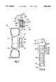
- FIG. 7 through 13(d)show a second embodiment of the present invention wherein:
- FIG. 7is a sectional view taken along a line I-I in FIG. 12;
- FIG. 8is an enlarged view of the upper portion of a king pin shaft
- FIG. 9is a sectional view of a driving motor
- FIG. 10is a perspective view of a rotor of a driving motor
- FIG. 11is a perspective view of a squirrel-cage rotor
- FIG. 12is a schematic plan view showing the arrangement of wheels of an electric vehicle of the present invention.
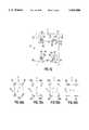
- FIG. 13is an explanatory drawing showing the traveling condition of an electric vehicle of the present invention wherein:
- FIG. 13(a)is an explanatory drawing of an oblique traveling
- FIG. 13(b)is an explanatory drawing of a small-turn traveling
- FIG. 13(d)is an explanatory drawing of a sidewise traveling.
- FIGS. 14(a) and 14(b)show a schematic drawing of an electric circuit of an embodiment of the present invention.
- FIGS. 1 through 6there is shown an electric vehicle 1 of a first embodiment of the present invention.
- the electric vehicle shownis a 4-wheel drive type vehicle (hereinafter referred to "4WD” as vehicle) having a function of 4-wheel steering (hereinafter referred to as "4WS”), a function of anti-skid brake system (hereinafter referred to as "ABS”) and a function of traction control.
- 4WD4-wheel drive type vehicle
- 4WS4-wheel steering
- ABSanti-skid brake system
- traction controla function of traction control
- the electric vehicle 1 of the present inventionhas two front wheels 2a and 2b arranged at both sides of the front direction (arrow F) of the vehicle, two rear wheels 3a and 3b and a body 4 supported on the front and rear wheels 2a and 2b, 3a and 3d.
- a front seat 6 and rear seat 7within a cabin 5 formed by the body 4.
- An acceleration pedal 11 for controlling the rotational speed of the front and rear wheels 2a and 2b, 3a and 3b and a brake pedal 12 for operating a hydraulic braking system(not shown) are also arranged in front of the front seat 6.
- FIG. 1shows a power transmitting apparatus (i.e. a driving apparatus) of the electric vehicle 1 of the present invention.
- Each of the driving motors 21a21b, 22a and 22bis driven by electric power from the batteries 13 and is independently controlled by signals from the controller 14.
- the controller 14 for controlling the driving motors 21a, 21b, 22a and 22b of the electric vehicle 1is constructed as shown in the block diagram of FIG. 3.
- the controller 14has a computer 31 and four motor-controllers 32a, 32b, 33a and 33b.
- the driving motors 21a, 21b, 22a and 22bare independently controlled by signals from the motor-controllers 32a, 32b, 33a and 33b.
- Inputted into the computer 31are the following signals: signals from wheel rotation detecting sensors 34 each mounted in conjunction with each of the driving motors 21a, 21b, 22a and 22b for detecting the rotational speed of each wheel (the signal(s) are hereinafter referred to "wheel rotation signal(s)”); a steering angle signal from steering angle sensor 35 mounted on the column of the steering handle 8 (the signal is hereinafter referred to "steering signal)"; an acceleration order signal detected by an acceleration sensor 36 mounted on the acceleration pedal 11 (the signal is hereinafter referred to "acceleration signal”); and a brake order signal detected by a brake sensor 37 mounted on the brake pedal 12 (the signal is hereinafter referred to "brake signal”).
- the wheel rotation detecting sensor 34can be mounted on the wheel itself, or its axle.
- the signals mentioned aboveare operated in accordance with a program stored in a memory means such as a ROM (Read Only Memory) in the computer 31 and are compared with traveling data of the electric vehicle 1 stored in the memory means.
- the outputs from the computer 31are inputted into the motor-controllers 32a, 32b, 33a and 33b of the driving motors 21a, 21b, 22a and 22b to properly control the rotational condition thereof in order to obtain the optimum driving force and braking force of each wheel.
- Point MOis a turning center of the vehicle 1 when the vehicle 1 is steered by the steering handle 8 in a conventional manner.
- the vehicle 1is controlled by driving the radially outward front wheel 2a and rear wheel 3b at driving forces ⁇ F1 and ⁇ F3, respectively, and by driving the radially inward front and rear wheels 2a and 3a at a driving force ⁇ F2 smaller than the driving forces ⁇ F1 and ⁇ F3, or by braking the radially inward front and rear wheels 2a and 3a at braking forces ⁇ R2 and ⁇ R4, a steering effect similar to a caterpillar-type vehicle arises between the right and left rear wheels 3a and 3b. Accordingly, the turning center of the vehicle 1 occupies a position M which is nearer to the body of vehicle 1 than the position MO and the turning radius of the vehicle is reduced. That is, the 4WS effect is thus easily achieved according to the present invention.
- This embodiment of the present inventionintends to improve the stability of the vehicle at high speed traveling. It does so by controlling the driving force and the braking force of each wheel, and by generating a moderate yawing moment cancelling the excessive yawing moment, making the instantaneous traveling direction of vehicle coincident with the direction of the body of vehicle.
- Regenerative brakingrefers to a system of dynamic braking in which the energy of a load (i.e., kinetic energy of the moving electric vehicle 1) is applied to the electric drive motors (e.g., motors 21a, 21b, 22a and 22b) so that the motors act as generators. Electric power produced by the motors is returned to the electric power supply (i.e., the storage batteries 13 of electric vehicle 1). Such electric power acts as braking force opposite in direction to the driving force of the motors of the traveling vehicle.
- this systemis characterized in that the electric power according to the braking force is returned to the electric power supply (batteries 13) and in that fine adjustments of the braking force are carried out electrically accurately and easily.
- a regenerative braking systemhas advantages over a conventional braking system by, e.g., improving the stability in vehicle travel by reducing to substantially zero the angle of sideslip caused when changing traffic lanes or turning to the right or left, and by providing neutral-steering (neither over- nor under-steering) when turning the vehicle. Further, a regenerative braking system returns the kinetic energy used to slow down the vehicle to the electric supply system (batteries 13).
- FIGS. 14a and 14bTo further explain the operation of regenerative braking, reference should be made to FIGS. 14a and 14b.
- the battery 81 and the drive motor 82are connected with each other via a chopper 83.
- This chopper 83serves to control the intensity of an electric current running between the two. A field current is caused to run with given intensity.
- the chopperhas the following two functions. First, it causes the electric current to run from the battery side to the drive motor side. (This function is referred to as a driving function.) Second, it causes the electric current to run from the drive motor side to the battery side. (This function is referred to as a braking function.) For convenience of illustration, the two functions will be represented as in FIG. 14b, where the sign denotes a flow direction of the electric power, the direction being reversible according to either function.
- the driving function of the chopper 83begins to be performed by detecting a press of an accelerator pedal of the vehicle.
- the intensity of the electric current running from the battery 81 to the drive motor 82is controlled by a working amount of the press of the accelerator pedal and thereby the driving force of the drive motor 82 is adjusted, so that the vehicle can travel at desired speed. (The stronger the pedal is pressed, the more the current runs.)
- Fine adjustments to the intensity of the braking forcemay be made by controlling the intensity of the electric current which the chopper 83 causes to run during braking.
- a strong currentis caused to run in order to obtain powerful braking force, while a weak current is caused to run in order to obtain powerless braking force. For example, when the electric vehicle travels through a street having many traffic signals and must stop and start frequently in a cycle of:
- a reversible chopper for a direct current motor and a VVVF inverter (variable voltage variable frequency inverter) for an alternating current motormay be used. These can easily switch from the driving function to the braking function and vice versa in response to a weak electric signal and further can easily control the intensity of a current, i.e., the intensities of driving force and braking force by giving an electric command.
- each of the wheels 2a, 2b, 3a and 3bis provided with individual driving motors 21a, 21b, 22a and 22b respectively, the function of full-time 4WD can be easily achieved by so controlling each driving motor that the rotational speed of wheels traveling in a straight direction becomes identical for each wheel.
- each wheel 2a, 2b, 3a and 3bis provided with a driving motor for individually driving its related wheel, it is possible to improve the braking phenomenon by properly controlling the driving motors so that the rotational speed of the driving motors (e.g. driving motor 22a) for the radially inward wheels (e.g. rear wheel 3a having the smallest turning radius) becomes lower than the rotational speed of the driving motors (e.g. driving motor 21b) for the radially outward wheels (e.g. front wheel 2b having the largest turning radius).
- the driving motorse.g. driving motor 22a
- the radially inward wheelse.g. rear wheel 3a having the smallest turning radius
- the braking force and the driving force of each driving motorare adapted to be determined or corrected by determining the angular acceleration of each wheel. This acceleration is based upon the wheel rotation signals from the wheel rotation sensors 34 mounted on each of the wheels 2a, 2b, 3a and 3b, by determining the required braking force and the required angular acceleration of each wheel from braking signals, the steering signals, the vehicle speed and e.g. previously stored limit braking force, and by considering the road surface conditions.
- the limit braking forcecan be determined by operating signals from each of the sensors. Adjustment of the braking force can be achieved by adjusting the regenerating braking force and the driving force of each of the driving motors.
- the driving force and the braking force of each of the driving motorsare corrected, the driving force and the braking force of each of the driving motors never exceed the limit braking force, and prevent the skid of the vehicle 1 while being braked.
- the function ABScan be obtained.
- Previously stored in the memory means of computer 31is a limit value of the rotational angular acceleration of each wheel of vehicle 1 of this embodiment, which can be adapted to a road surface condition having a small coefficient of friction (such as a snow-covered road).
- the driving force of each driving motorcan be determined by the rotational angular acceleration of each wheel (from the wheel rotation signal).
- the required angular acceleration of each wheelcan be obtained by determining the required driving force and the required angular acceleration of each wheel, and by considering the road surface condition.
- the limit driving forcemay be determined by an operated value of a signal from each sensor.
- the resulting operationnever exceeds said limit value, even though the acceleration order exceeds the limit driving force.
- the function of traction controlcan be obtained by limiting the transmission of the acceleration order to each driving motor.
- the signals from the sensorsare processed by computer 31 along a program shown in FIGS. 6A and 6B in order to effectively exhibit all of the functions mentioned above.
- the wheel rotation signals from each of the wheel rotation sensors 34 mounted on driving motors 21a, 21b, 22a and 22b of wheels 2a, 2b, 3a and 3bare inputted into the computer 31 and the speed of the vehicle 1 is determined therefrom (STEP "A").
- the acceleration signal from acceleration sensor 36 arranged at acceleration pedal 11, and the braking signal from brake sensor 37 arranged at brake pedal 12,are inputted into computer 31, and computer 31 determines from these acceleration and braking signals whether the vehicle 1 is decelerated or not (STEP "B").
- the programgoes to a STEP “C” on deceleration, and to a STEP “G” on acceleration or constant speed.
- the required braking force and the required angular accelerationare determined from the braking signal, the vehicle speed and the limit braking force at the STEP "C” and then it goes to a STEP "D".
- the braking force (torque) and driving force (torque) of each driving motorare determined, in consideration of the road surface condition, from the angular acceleration of each wheel (obtained from each wheel rotation signal) and the required angular acceleration of each wheel.
- the programgoes to a STEP "E”.
- the programdetermines at STEP "E” (by the steering signal from the steering angle sensor 35) whether vehicle 1 is now in a turn or not It goes to STEP “F” in case of a "yes", and it is outputted to the motor controller in case of a "no".
- the required angular acceleration of each wheelis corrected at STEP "F", comparing the limit braking force in consideration of the cornering force due to the turn of vehicle 1. Then, the determined results of the amount of control for each driving motor are outputted to each motor controller.
- STEPS "G” and "H”correspond to the function of traction control.
- the driving force and the braking forceare determined at STEP "K", in order to obtain the corrected value (i e., the braking phenomenon preventing function for traveling in 4WD mode) from the steering signal and from each wheel rotation signal in consideration of the difference in traveling distance between the radially inward wheels and the radially outward wheels. Then the program goes to STEP "L".
- the corrected valuei e., the braking phenomenon preventing function for traveling in 4WD mode
- the yawing moment of the vehicle 1is determined at STEP “P” from the steering signal, each wheel rotation signal, and the vehicle speed, thus obtaining the corrected value of each driving force for cancelling the yawing moment (i.e., the 4WS function for traveling at high speed).
- the difference in the driving force between the driving wheels for minimizing the turning radius of the vehicleis determined from the steering signal, each wheel rotation signal, and the vehicle speed, thus obtaining a corrected value of the driving force of each driving wheel (i.e., the 4WS function for traveling at low speed).
- the corrected value of each driving force thus obtainedis then inputted to the motor controller of each driving motor and is used to properly adjust the driving force and the braking force of each wheel.
- control systemis constructed as a single computer system, adapted to achieve the travel control and attitude control of the vehicle by effectively utilizing the signals obtained during the travel of the vehicle and by controlling the driving force and the braking force of each wheel, it is possible to improve the stability in travel of the vehicle and thus the driving characteristics of the electric vehicle.
- An electric vehicle 51 (FIG. 12) of the second embodimentis a 4-wheeled automobile having a 4WS function, wherein each wheel of the vehicle is mounted on a king pin shaft swivelably therearound.
- the construction of a steering mechanism, a driving mechanism and a suspension mechanism (FIG. 12)are clearly shown in FIG. 7.
- a numeral 52denotes a wheel and a numeral 53 denotes a frame.
- a supporting means 54is secured on one side of the frame 53 and has a through bore 54a.
- Bearings 54bare arranged at top and bottom ends of the bore 54a.
- the wheel 52is mounted on the bottom end of king pin shaft 55 which is passed through bore 54a of supporting means 54.
- the upper portion of king pin shaft 55is integrally formed with a flange portion 55a, and the lower end portion of king pin shaft 55 is integrally secured to base plate 57 by welding and other suitable ways.
- the base plate 57forms a frame for a driving motor hereinafter mentioned and is adapted to horizontally support an axle 65.
- a coil spring 54dis interposed between a washer 54c mounted on the upper surface of flange portion 55a and the lower surface of upper bearing 54b secured on supporting means 54.
- the king pin shaft 55is vertically movable relative to supporting means 54 and also is movable around its own axis.
- a boss 71 and a boss aperture 74is formed at the center of base plate 57.
- a stator coil 73is secured around the outer circumferential surface of boss 71, and axle 65 of wheel 52 is rotatably mounted in boss aperture 74 (see FIG. 9).
- Axle 65is rigidly fixed to rotor frame 76, which is secured to wheel rim 61 of wheel 52. Axle 65 is projected inside base plate 57 and a brake disc 66 is secured on the inner end of axle 65.
- Brake caliper 67 supported on base plate 57is so arranged that it faces the peripheral surfaces of brake disc 66 to provide the braking action thereto.
- a numeral 68denotes a tire of wheel 52.
- a worm wheel 64is secured on the end of king pin shaft 55 above supporting means 54, and worm 63 driven by geared motor 62 is arranged near worm wheel 64 to mesh therewith.
- wheel 52When driving geared motor 62, wheel 52 is steered via king pin shaft 55, base plate 57 and axle 65.
- Worm wheel 64is fitted on a splined portion 55g of king pin shaft 55. Therefore, it is always kept in a matching position with worm 63 and enables the power transmission therebetween despite the vertical movement of king pin shaft 55.
- an outer-rotor type induction motor 56is constructed as a wheel driving motor between base plate 57 and rim 61 of wheel 52.
- driving motor 56comprises a stator 58 and a rotor 59.
- a yoke 72 formed by a plurality of laminated steel platesis mounted on boss portion 71 therearound and a stator coil 73 is wound in yoke 72.
- Axle 65 forming a shaft of rotor 59is rotatably supported by bearings 75 arranged within aperture 74 of boss portion 71.
- rotor 59is formed by rotor frame 76 and axle 65 arranged at the center of rotor frame 76.
- the squirrel-cage rotor 77 shown in FIG. 11is fitted within rotor frame 76 along the inner peripheral surface thereof.
- Squirrel-cage rotor 77is formed by two ends rings 78 and a plurality of conductors 79, and acts as a rotor coil generating a rotational force relative to stator coil 73.
- Driving motor 56is thus formed by inserting the shaft of rotor 59, i.e., axle 65, into bearings 75 mounted in aperture 74 of boss 71 of stator 58.
- driving motor 56 of the second embodiment of the present inventionsince rotor 59 is rotatably positioned around stator 58, it is easy to form driving motor 56 by merely connecting rotor frame 76 of rotor 59 to rim 61 of wheel 52 by using fastening means such as bolts.
- the electric poweris supplied to driving motor 56 via a joint portion 69 arranged above king pin shaft 55.
- joint portion 69comprises slip rings 55c which are electrically isolated from each other by isolating rings 55b and carbon brushes 55d, each contacting the peripheral surface of each slip ring 55c.
- Electric cables connected to slip rings 55care passed through an aperture 55e formed in king pin shaft 55 and are led to driving motor 56.
- aperture 55e formed in king pin shaft 55also has a function of a passage of the pressurized liquid supplied via a swivel joint 55 for operating brake caliper 67.
- the driving means for each wheel 52i.e., driving motor 56
- the driving means for each wheel 52comprises stator 58 arranged coaxially with axle 65 and rotor 59 formed in rim 61 of each wheel 52 and fitted around stator 58, it is possible to eliminate any mechanical power transmission structure to impart the driving force to each wheel 52.
- vehicle 51can continue an oblique travel keeping the attitude of vehicle 51 in the constant oblique direction.
- driving motor 56 of each wheel 52is adapted to be positioned within rim 61 of each wheel 52, a large projection required in the prior art for the installation of the driving motor is eliminated. Therefore, a large space can be maintained between wheels 52.
- wheel driving motorscan be installed integrally with the steering wheel, it is possible to eliminate the power transmitting mechanisms to the steering wheels, thus simplifying the mechanism of the vehicle.
- Thiscan reduce the structural members which would disturb the turning action of the steering wheels around their king pin shafts. Thus, it can increase the angular range of turning action of the steering wheels, and can therefore improve the motion characteristics of the vehicle.
Landscapes
- Engineering & Computer Science (AREA)
- Transportation (AREA)
- Mechanical Engineering (AREA)
- Power Engineering (AREA)
- Life Sciences & Earth Sciences (AREA)
- Sustainable Development (AREA)
- Sustainable Energy (AREA)
- Chemical & Material Sciences (AREA)
- Combustion & Propulsion (AREA)
- Electric Propulsion And Braking For Vehicles (AREA)
- Arrangement Or Mounting Of Propulsion Units For Vehicles (AREA)
Abstract
Description
Claims (2)
Priority Applications (1)
| Application Number | Priority Date | Filing Date | Title |
|---|---|---|---|
| US08/059,335US5465806A (en) | 1989-03-31 | 1993-05-11 | Electric vehicle |
Applications Claiming Priority (6)
| Application Number | Priority Date | Filing Date | Title |
|---|---|---|---|
| JP1083374AJP2984724B2 (en) | 1989-03-31 | 1989-03-31 | Electric car |
| JP1-83374 | 1989-03-31 | ||
| JP1-317345 | 1989-12-06 | ||
| JP1317345AJP2685315B2 (en) | 1989-12-06 | 1989-12-06 | Electric car |
| US07/613,756US5222568A (en) | 1989-03-31 | 1990-03-30 | Electric vehicle |
| US08/059,335US5465806A (en) | 1989-03-31 | 1993-05-11 | Electric vehicle |
Related Parent Applications (1)
| Application Number | Title | Priority Date | Filing Date |
|---|---|---|---|
| US07/613,756Continuation-In-PartUS5222568A (en) | 1989-03-31 | 1990-03-30 | Electric vehicle |
Publications (1)
| Publication Number | Publication Date |
|---|---|
| US5465806Atrue US5465806A (en) | 1995-11-14 |
Family
ID=27304212
Family Applications (1)
| Application Number | Title | Priority Date | Filing Date |
|---|---|---|---|
| US08/059,335Expired - LifetimeUS5465806A (en) | 1989-03-31 | 1993-05-11 | Electric vehicle |
Country Status (1)
| Country | Link |
|---|---|
| US (1) | US5465806A (en) |
Cited By (85)
| Publication number | Priority date | Publication date | Assignee | Title |
|---|---|---|---|---|
| US5680908A (en)* | 1996-01-29 | 1997-10-28 | Reed; Louis | Electric powered vehicle |
| US5726890A (en)* | 1992-03-19 | 1998-03-10 | Hitachi, Ltd. | Control apparatus for electric vehicle |
| US5988307A (en)* | 1995-05-19 | 1999-11-23 | Toyota Jidosha Kabushiki Kaisha | Power transmission apparatus, four-wheel drive vehicle with power transmission apparatus incorporated therein, method of transmitting power, and method of four-wheel driving |
| US6024182A (en)* | 1995-09-11 | 2000-02-15 | Honda Giken Kogyo Kabushiki Kaisha | Coupling device between left and right wheels of vehicle |
| US6040561A (en)* | 1999-06-30 | 2000-03-21 | General Motors Corporation | High voltage bus and auxiliary heater control system for an electric or hybrid vehicle |
| US6044924A (en)* | 1996-11-04 | 2000-04-04 | Adli; Manoucher | Hot compressed gas powered vehicle |
| US6081081A (en)* | 1995-10-07 | 2000-06-27 | Robert Bosch Gmbh | Electric motor-driven wheel brake for vehicles |
| WO2000037304A1 (en)* | 1998-12-22 | 2000-06-29 | Radebold, Walter | Vehicle |
| US6220379B1 (en)* | 1996-02-13 | 2001-04-24 | Dane Industries, Inc. | Cart retriever vehicle |
| US6231134B1 (en)* | 1997-09-16 | 2001-05-15 | Toyota Jidosha Kabushiki Kaisha | Vehicle braking system having frictional and regenerative braking devices |
| WO2001076902A1 (en)* | 2000-04-10 | 2001-10-18 | Compact Dynamics Gmbh | System of electrical machines whose rotors are each connected to a wheel of a motor vehicle |
| EP0982175A3 (en)* | 1998-08-24 | 2002-01-23 | Mitsubishi Heavy Industries, Ltd. | Regenerative braking apparatus for battery vehicle |
| US6386305B2 (en)* | 1998-08-24 | 2002-05-14 | Tsubishi Heavy Industries, Ltd. | Propulsion motor control apparatus for battery vehicle |
| US20030010550A1 (en)* | 2001-05-24 | 2003-01-16 | Prucher Bryan P. | Motor in wheel electric drive system |
| US20030079924A1 (en)* | 2001-10-25 | 2003-05-01 | Tsutomu Wakitani | Eletrcic vehicle |
| US20030105563A1 (en)* | 2001-11-16 | 2003-06-05 | Kanazawa Institute Of Technology | Electric vehicle steering/drive control method, electric vehicle steering/drive control apparatus, and electric vehicle |
| FR2840577A1 (en)* | 2002-06-11 | 2003-12-12 | Renault Sa | METHOD AND DEVICE FOR CORRECTING THE TRAJECTORY OF A HYBRID MOTOR VEHICLE ASSOCIATED WITH AN ELECTRONIC STABILITY PROGRAM |
| US20030230933A1 (en)* | 2002-06-17 | 2003-12-18 | Ford Motor Company | Control of regenerative braking during a yaw stability control event |
| US6691809B2 (en)* | 2000-08-29 | 2004-02-17 | Toyota Jidosha Kabushiki Kaisha | Power output apparatus, motor vehicle including power output apparatus and control methods thereof |
| US20040074687A1 (en)* | 2000-05-02 | 2004-04-22 | Mellot Lex A. | Four-wheel drive assist for electric machines |
| WO2004071800A1 (en)* | 2003-02-06 | 2004-08-26 | Wavecrest Laboratories Llc | Adaptive electric vehicle |
| US20040176899A1 (en)* | 2003-03-07 | 2004-09-09 | Hallowell Stephen James | Torque distribution systems and methods for wheeled vehicles |
| US20040230361A1 (en)* | 2003-05-14 | 2004-11-18 | Kanazawa Institute Of Technology | Electric vehicle steering/drive control method |
| US20040263099A1 (en)* | 2002-07-31 | 2004-12-30 | Maslov Boris A | Electric propulsion system |
| US20050046375A1 (en)* | 2002-07-31 | 2005-03-03 | Maslov Boris A. | Software-based adaptive control system for electric motors and generators |
| US20050045392A1 (en)* | 2002-07-31 | 2005-03-03 | Maslov Boris A. | In-wheel electric motors |
| US20050052080A1 (en)* | 2002-07-31 | 2005-03-10 | Maslov Boris A. | Adaptive electric car |
| US6877577B1 (en) | 2002-01-02 | 2005-04-12 | Roger Smith | Vehicle all-wheel drive system |
| US20050151420A1 (en)* | 2001-05-07 | 2005-07-14 | Dale Crombez | Hybrid electric vehicle powertrain with regenerative braking |
| US20050252701A1 (en)* | 2002-09-24 | 2005-11-17 | Hiroshi Shimizu | Driver of electric automobile |
| US20060016630A1 (en)* | 2003-04-07 | 2006-01-26 | Tai-Her Yang | Repulsive differential driving double-acting type electrical machinery power system |
| US20060054368A1 (en)* | 2004-09-16 | 2006-03-16 | Varela Tomaz D | Electric drive axle assembly with independent dual motors |
| EP1353836A4 (en)* | 2000-09-25 | 2006-03-22 | Its Bus Inc | Platforms for sustainable transportation |
| US20060102395A1 (en)* | 2004-11-12 | 2006-05-18 | Honda Motor Co., Ltd. | Regeneration control system |
| EP1359045A3 (en)* | 2002-04-25 | 2006-05-31 | Toyoda Koki Kabushiki Kaisha | Drive system for automotive vehicle of front-and-rear wheel drive type |
| US20060124368A1 (en)* | 2003-03-28 | 2006-06-15 | Plishner Paul J | Vehicle with a distributed motor |
| US7083015B2 (en)* | 1997-02-18 | 2006-08-01 | Meritor Heavy Vehicle Systems, Llc | Low floor drive unit assembly for an electrically driven vehicle |
| US20060225930A1 (en)* | 2005-04-07 | 2006-10-12 | Schulte Juergen J | Dual axle electric motor drive and method of use |
| US20060237242A1 (en)* | 2000-09-25 | 2006-10-26 | Burke Robert J | Lightweight surface vehicle |
| US20060260859A1 (en)* | 2005-05-19 | 2006-11-23 | Deere & Company, A Delaware Corporation | Steering responsive wheel drive system |
| US20070105683A1 (en)* | 2003-09-26 | 2007-05-10 | Koji Irikura | Hydraulic Steering Transaxle and Hydraulic Driving Vehicle |
| US20070144797A1 (en)* | 2003-09-20 | 2007-06-28 | Nicolai Tarasinski | Steering system for an agricultural or industrial utility vehicle and method for operating a steering system |
| WO2007107570A1 (en)* | 2006-03-23 | 2007-09-27 | Michelin Recherche Et Technique S.A. | Ground interface for a vehicle |
| US7332881B2 (en) | 2004-10-28 | 2008-02-19 | Textron Inc. | AC drive system for electrically operated vehicle |
| US20080319619A1 (en)* | 2007-06-21 | 2008-12-25 | Honda Motor Co., Ltd. | Vehicle drive control system |
| DE10120742B4 (en)* | 2001-04-20 | 2009-03-05 | Brose Fahrzeugteile Gmbh & Co. Kommanditgesellschaft, Coburg | Wheel Drive |
| US20100133023A1 (en)* | 2009-01-29 | 2010-06-03 | Tesla Motors, Inc. | All wheel drive electric vehicle power assist drive system |
| US20100155161A1 (en)* | 2008-10-15 | 2010-06-24 | Martin Eugenio Corradini | Turbine-based power-generating system for hybrid and electric automobiles, cars, transports, machinery and motorcycles |
| US20100180792A1 (en)* | 2007-04-20 | 2010-07-22 | Rolic Invest S.A. R. L. | Cable transportation system and relative drive method |
| US20100222953A1 (en)* | 2009-01-29 | 2010-09-02 | Tesla Motors, Inc. | Dual Motor Drive and Control System for an Electric Vehicle |
| EP1951542A4 (en)* | 2005-11-09 | 2010-11-03 | Evans Electric Pty Ltd | Vehicle drive system |
| US7926889B2 (en) | 2007-10-29 | 2011-04-19 | Textron Innovations Inc. | Hill hold for an electric vehicle |
| RU2421354C2 (en)* | 2006-06-22 | 2011-06-20 | Тойота Дзидося Кабусики Кайся | Automotive drive device |
| US20120043144A1 (en)* | 2010-08-20 | 2012-02-23 | Hyundai Motor Company | Power transmission device for electric vehicle |
| US8127873B1 (en)* | 2007-06-26 | 2012-03-06 | Walsh Robert D | Electric powered automobile/wheel turbine motor |
| US20120217080A1 (en)* | 2011-02-25 | 2012-08-30 | Besler Mark J | Powered vehicle with an independent and interchangeable powertrain assembly |
| US20130030601A1 (en)* | 2011-07-28 | 2013-01-31 | Hyundai Motor Company | Control system and method of vehicle using in-wheel motor |
| US20130090796A1 (en)* | 2011-10-11 | 2013-04-11 | Volvo Car Corporation | Motor assembly |
| US20140216831A1 (en)* | 2013-02-01 | 2014-08-07 | Daniel James LAMBERT | Self Charging Electric Vehicle |
| US20150060172A1 (en)* | 2010-05-14 | 2015-03-05 | Carl Manganaro | Drive system for a motor vehicle |
| US9400502B2 (en) | 2004-09-13 | 2016-07-26 | Deka Products Limited Partnership | Control of a personal transporter based on user position |
| US20160257191A1 (en)* | 2015-03-06 | 2016-09-08 | George Dickens, JR. | Vehicular Drive Assembly |
| US9545963B2 (en) | 2002-07-12 | 2017-01-17 | DEKA Products Limited Partnership LLP | Control of a transporter based on attitude |
| EP3138718A4 (en)* | 2014-04-29 | 2017-05-03 | Zhejiang Geely Holding Group Co., Ltd. | Integrated steering drive axle for vehicle and electric vehicle |
| US9809129B2 (en) | 2015-10-27 | 2017-11-07 | Thunder Power New Energy Vehicle Development Company Limited | Four motor direct driving system |
| US10023073B2 (en)* | 2015-10-27 | 2018-07-17 | Thunder Power New Energy Vehicle Development Company Limited | Four motor direct driving system |
| CN108608847A (en)* | 2018-06-12 | 2018-10-02 | 芜湖爱丽机电科技有限公司 | A kind of drive system of electric motor vehicle |
| US10093308B2 (en) | 2014-09-01 | 2018-10-09 | Ntn Corporation | Electronic stability control system for vehicle |
| CN108790782A (en)* | 2018-06-12 | 2018-11-13 | 芜湖爱丽机电科技有限公司 | Driving structure of electric vehicle |
| CN108790783A (en)* | 2018-06-12 | 2018-11-13 | 芜湖爱丽机电科技有限公司 | Drive system of electric motor vehicle |
| US20180326295A1 (en)* | 2013-12-05 | 2018-11-15 | Aaron Benjamin Aders | Technologies for transportation |
| US10220843B2 (en) | 2016-02-23 | 2019-03-05 | Deka Products Limited Partnership | Mobility device control system |
| USD846452S1 (en) | 2017-05-20 | 2019-04-23 | Deka Products Limited Partnership | Display housing |
| US20190217696A1 (en)* | 2016-09-21 | 2019-07-18 | Ntn Corporation | Vehicle power assist system |
| US10442310B1 (en)* | 2014-03-10 | 2019-10-15 | Dean Drako | Vehicle yaw and energy efficiency control apparatus to dynamically assign torque among independently powered drive wheels |
| US10802495B2 (en) | 2016-04-14 | 2020-10-13 | Deka Products Limited Partnership | User control device for a transporter |
| US10908045B2 (en) | 2016-02-23 | 2021-02-02 | Deka Products Limited Partnership | Mobility device |
| AU2019246809B2 (en)* | 2013-12-05 | 2021-02-11 | Aaron Benjamin ADERS | Technologies for transportation |
| US10926756B2 (en) | 2016-02-23 | 2021-02-23 | Deka Products Limited Partnership | Mobility device |
| USD915248S1 (en) | 2017-05-20 | 2021-04-06 | Deka Products Limited Partnership | Set of toggles |
| US11399995B2 (en) | 2016-02-23 | 2022-08-02 | Deka Products Limited Partnership | Mobility device |
| US11681293B2 (en) | 2018-06-07 | 2023-06-20 | Deka Products Limited Partnership | System and method for distributed utility service execution |
| USD1047785S1 (en) | 2017-05-20 | 2024-10-22 | Deka Products Limited Partnership | Toggle control device |
| USD1048216S1 (en)* | 2022-09-07 | 2024-10-22 | Laltitude Llc | Magnetic block |
| US12440401B2 (en) | 2024-05-22 | 2025-10-14 | Deka Products Limited Partnership | Mobility device |
Citations (9)
| Publication number | Priority date | Publication date | Assignee | Title |
|---|---|---|---|---|
| US4157123A (en)* | 1978-03-06 | 1979-06-05 | Everest & Jennings, Inc. | Wheelchair electrical control circuit |
| DE2812491A1 (en)* | 1978-03-22 | 1979-09-27 | Bbc Brown Boveri & Cie | Battery powered vehicle traction control - uses regenerative braking with speed related bias on pole windings to limit battery size |
| JPS57158163A (en)* | 1981-03-23 | 1982-09-29 | Iseki & Co Ltd | Tractor steering drive system |
| FR2561593A1 (en)* | 1984-03-26 | 1985-09-27 | Bruyant Guy | Electric drive wheel |
| US4770266A (en)* | 1985-08-13 | 1988-09-13 | Mazda Motor Corporation | Brake control system for four-wheel drive vehicle |
| US4805712A (en)* | 1986-04-01 | 1989-02-21 | The Spastics Society | Wheelchair |
| US5148883A (en)* | 1989-12-27 | 1992-09-22 | Aisin Aw Co., Ltd. | Regenerative braking electric vehicle with four motors |
| US5222568A (en)* | 1989-03-31 | 1993-06-29 | Kabushiki Kaisha Shikoku Sogo Kenkyujo | Electric vehicle |
| US5318355A (en)* | 1991-12-05 | 1994-06-07 | Honda Giken Kogyo Kabushiki Kaisha | Brake system in electric vehicle |
- 1993
- 1993-05-11USUS08/059,335patent/US5465806A/ennot_activeExpired - Lifetime
Patent Citations (9)
| Publication number | Priority date | Publication date | Assignee | Title |
|---|---|---|---|---|
| US4157123A (en)* | 1978-03-06 | 1979-06-05 | Everest & Jennings, Inc. | Wheelchair electrical control circuit |
| DE2812491A1 (en)* | 1978-03-22 | 1979-09-27 | Bbc Brown Boveri & Cie | Battery powered vehicle traction control - uses regenerative braking with speed related bias on pole windings to limit battery size |
| JPS57158163A (en)* | 1981-03-23 | 1982-09-29 | Iseki & Co Ltd | Tractor steering drive system |
| FR2561593A1 (en)* | 1984-03-26 | 1985-09-27 | Bruyant Guy | Electric drive wheel |
| US4770266A (en)* | 1985-08-13 | 1988-09-13 | Mazda Motor Corporation | Brake control system for four-wheel drive vehicle |
| US4805712A (en)* | 1986-04-01 | 1989-02-21 | The Spastics Society | Wheelchair |
| US5222568A (en)* | 1989-03-31 | 1993-06-29 | Kabushiki Kaisha Shikoku Sogo Kenkyujo | Electric vehicle |
| US5148883A (en)* | 1989-12-27 | 1992-09-22 | Aisin Aw Co., Ltd. | Regenerative braking electric vehicle with four motors |
| US5318355A (en)* | 1991-12-05 | 1994-06-07 | Honda Giken Kogyo Kabushiki Kaisha | Brake system in electric vehicle |
Cited By (160)
| Publication number | Priority date | Publication date | Assignee | Title |
|---|---|---|---|---|
| US5726890A (en)* | 1992-03-19 | 1998-03-10 | Hitachi, Ltd. | Control apparatus for electric vehicle |
| US5988307A (en)* | 1995-05-19 | 1999-11-23 | Toyota Jidosha Kabushiki Kaisha | Power transmission apparatus, four-wheel drive vehicle with power transmission apparatus incorporated therein, method of transmitting power, and method of four-wheel driving |
| US6105704A (en)* | 1995-09-11 | 2000-08-22 | Honda Giken Kogyo Kabushiki Kaisha | Coupling device between left and right wheels of vehicle |
| US6024182A (en)* | 1995-09-11 | 2000-02-15 | Honda Giken Kogyo Kabushiki Kaisha | Coupling device between left and right wheels of vehicle |
| US6325736B1 (en) | 1995-09-11 | 2001-12-04 | Honda Giken Kogyo Kabushiki Kaisha | Coupling device between left and right wheels of vehicle |
| US6081081A (en)* | 1995-10-07 | 2000-06-27 | Robert Bosch Gmbh | Electric motor-driven wheel brake for vehicles |
| US5680908A (en)* | 1996-01-29 | 1997-10-28 | Reed; Louis | Electric powered vehicle |
| US6220379B1 (en)* | 1996-02-13 | 2001-04-24 | Dane Industries, Inc. | Cart retriever vehicle |
| US6044924A (en)* | 1996-11-04 | 2000-04-04 | Adli; Manoucher | Hot compressed gas powered vehicle |
| US7083015B2 (en)* | 1997-02-18 | 2006-08-01 | Meritor Heavy Vehicle Systems, Llc | Low floor drive unit assembly for an electrically driven vehicle |
| US6231134B1 (en)* | 1997-09-16 | 2001-05-15 | Toyota Jidosha Kabushiki Kaisha | Vehicle braking system having frictional and regenerative braking devices |
| US6386305B2 (en)* | 1998-08-24 | 2002-05-14 | Tsubishi Heavy Industries, Ltd. | Propulsion motor control apparatus for battery vehicle |
| EP0982175A3 (en)* | 1998-08-24 | 2002-01-23 | Mitsubishi Heavy Industries, Ltd. | Regenerative braking apparatus for battery vehicle |
| WO2000037304A1 (en)* | 1998-12-22 | 2000-06-29 | Radebold, Walter | Vehicle |
| US9411336B2 (en) | 1999-06-04 | 2016-08-09 | Deka Products Limited Partnership | Control of a personal transporter based on user position |
| US9442491B2 (en) | 1999-06-04 | 2016-09-13 | Deka Products Limited Partnership | Control of a personal transporter based on user position |
| US10118661B2 (en) | 1999-06-04 | 2018-11-06 | Deka Products Limited Partnership | Control of a personal transporter based on user position |
| US9411340B2 (en) | 1999-06-04 | 2016-08-09 | Deka Products Limited Partnership | Control of a personal transporter based on user position |
| US9442492B2 (en) | 1999-06-04 | 2016-09-13 | Deka Products Limited Partnership | Control of a personal transporter based on user position |
| US6040561A (en)* | 1999-06-30 | 2000-03-21 | General Motors Corporation | High voltage bus and auxiliary heater control system for an electric or hybrid vehicle |
| WO2001076902A1 (en)* | 2000-04-10 | 2001-10-18 | Compact Dynamics Gmbh | System of electrical machines whose rotors are each connected to a wheel of a motor vehicle |
| US6892846B2 (en) | 2000-05-02 | 2005-05-17 | Jlg Industries, Inc. | Four-wheel drive assist for electric machines |
| US20040074687A1 (en)* | 2000-05-02 | 2004-04-22 | Mellot Lex A. | Four-wheel drive assist for electric machines |
| US6691809B2 (en)* | 2000-08-29 | 2004-02-17 | Toyota Jidosha Kabushiki Kaisha | Power output apparatus, motor vehicle including power output apparatus and control methods thereof |
| EP1353836A4 (en)* | 2000-09-25 | 2006-03-22 | Its Bus Inc | Platforms for sustainable transportation |
| US20060237242A1 (en)* | 2000-09-25 | 2006-10-26 | Burke Robert J | Lightweight surface vehicle |
| DE10120742B4 (en)* | 2001-04-20 | 2009-03-05 | Brose Fahrzeugteile Gmbh & Co. Kommanditgesellschaft, Coburg | Wheel Drive |
| US20050151420A1 (en)* | 2001-05-07 | 2005-07-14 | Dale Crombez | Hybrid electric vehicle powertrain with regenerative braking |
| US6851496B2 (en)* | 2001-05-24 | 2005-02-08 | Bryan P. Prucher | Motor in wheel electric drive system |
| US20040211606A1 (en)* | 2001-05-24 | 2004-10-28 | Prucher Bryan P. | Motor in wheel electric drive system |
| US6948578B2 (en)* | 2001-05-24 | 2005-09-27 | Prucher Bryan P | Motor in wheel electric drive system |
| US20030010550A1 (en)* | 2001-05-24 | 2003-01-16 | Prucher Bryan P. | Motor in wheel electric drive system |
| US6860348B2 (en)* | 2001-10-25 | 2005-03-01 | Honda Giken Kogyo Kabushiki Kaisha | Electric vehicle |
| US20030079924A1 (en)* | 2001-10-25 | 2003-05-01 | Tsutomu Wakitani | Eletrcic vehicle |
| US20030105563A1 (en)* | 2001-11-16 | 2003-06-05 | Kanazawa Institute Of Technology | Electric vehicle steering/drive control method, electric vehicle steering/drive control apparatus, and electric vehicle |
| US6871125B2 (en)* | 2001-11-16 | 2005-03-22 | Kanazawa Institute Of Technology | Electric vehicle steering/drive control method, electric vehicle steering/drive control apparatus, and electric vehicle |
| US6877577B1 (en) | 2002-01-02 | 2005-04-12 | Roger Smith | Vehicle all-wheel drive system |
| EP1359045A3 (en)* | 2002-04-25 | 2006-05-31 | Toyoda Koki Kabushiki Kaisha | Drive system for automotive vehicle of front-and-rear wheel drive type |
| FR2840577A1 (en)* | 2002-06-11 | 2003-12-12 | Renault Sa | METHOD AND DEVICE FOR CORRECTING THE TRAJECTORY OF A HYBRID MOTOR VEHICLE ASSOCIATED WITH AN ELECTRONIC STABILITY PROGRAM |
| US20030230933A1 (en)* | 2002-06-17 | 2003-12-18 | Ford Motor Company | Control of regenerative braking during a yaw stability control event |
| US7093912B2 (en) | 2002-06-17 | 2006-08-22 | Ford Motor Company | Control of regenerative braking during a yaw stability control event |
| US10227098B2 (en) | 2002-07-12 | 2019-03-12 | Deka Products Limited Partnership | Control of a transporter based on attitude |
| US9545963B2 (en) | 2002-07-12 | 2017-01-17 | DEKA Products Limited Partnership LLP | Control of a transporter based on attitude |
| US11648995B2 (en) | 2002-07-12 | 2023-05-16 | Deka Products Limited Partnership | Control of a transporter based on attitude |
| US20040263099A1 (en)* | 2002-07-31 | 2004-12-30 | Maslov Boris A | Electric propulsion system |
| US20050052080A1 (en)* | 2002-07-31 | 2005-03-10 | Maslov Boris A. | Adaptive electric car |
| US20050046375A1 (en)* | 2002-07-31 | 2005-03-03 | Maslov Boris A. | Software-based adaptive control system for electric motors and generators |
| US20050045392A1 (en)* | 2002-07-31 | 2005-03-03 | Maslov Boris A. | In-wheel electric motors |
| US20050252701A1 (en)* | 2002-09-24 | 2005-11-17 | Hiroshi Shimizu | Driver of electric automobile |
| US7255185B2 (en)* | 2002-09-24 | 2007-08-14 | Japan Science And Technology Agency | Driver of electric automobile |
| CN100503306C (en)* | 2002-09-24 | 2009-06-24 | 独立行政法人科学技术振兴机构 | Drives for Electric Vehicles |
| WO2004071800A1 (en)* | 2003-02-06 | 2004-08-26 | Wavecrest Laboratories Llc | Adaptive electric vehicle |
| US6909959B2 (en) | 2003-03-07 | 2005-06-21 | Stephen James Hallowell | Torque distribution systems and methods for wheeled vehicles |
| US20040176899A1 (en)* | 2003-03-07 | 2004-09-09 | Hallowell Stephen James | Torque distribution systems and methods for wheeled vehicles |
| US20060124368A1 (en)* | 2003-03-28 | 2006-06-15 | Plishner Paul J | Vehicle with a distributed motor |
| US20060016630A1 (en)* | 2003-04-07 | 2006-01-26 | Tai-Her Yang | Repulsive differential driving double-acting type electrical machinery power system |
| US7184869B2 (en) | 2003-05-14 | 2007-02-27 | Kanazawa Institute Of Technology | Electric vehicle steering/drive control method |
| US20040230361A1 (en)* | 2003-05-14 | 2004-11-18 | Kanazawa Institute Of Technology | Electric vehicle steering/drive control method |
| US7748488B2 (en)* | 2003-09-20 | 2010-07-06 | Deere & Company | Steering system for an agricultural or industrial utility vehicle and method for operating a steering system |
| US20070144797A1 (en)* | 2003-09-20 | 2007-06-28 | Nicolai Tarasinski | Steering system for an agricultural or industrial utility vehicle and method for operating a steering system |
| US20070105683A1 (en)* | 2003-09-26 | 2007-05-10 | Koji Irikura | Hydraulic Steering Transaxle and Hydraulic Driving Vehicle |
| US7987669B2 (en) | 2003-09-26 | 2011-08-02 | Kanzaki Kokyukoki Mfg. Co., Ltd | Hydraulic steering transaxle and hydraulic driving vehicle |
| US7455145B2 (en)* | 2003-09-26 | 2008-11-25 | Kanzaki Kokyukoki Mfg. Co., Ltd. | Hydraulic steering transaxle and hydraulic driving vehicle |
| US20090047151A1 (en)* | 2003-09-26 | 2009-02-19 | Koji Irikura | Hydraulic Steering Transaxle And Hydraulic Driving Vehicle |
| US9442486B2 (en) | 2004-09-13 | 2016-09-13 | Deka Products Limited Partnership | Control of a personal transporter based on user position |
| US9400502B2 (en) | 2004-09-13 | 2016-07-26 | Deka Products Limited Partnership | Control of a personal transporter based on user position |
| US9429955B2 (en) | 2004-09-13 | 2016-08-30 | Deka Products Limited Partnership | Control of a personal transporter based on user position |
| US9983587B2 (en) | 2004-09-13 | 2018-05-29 | Deka Products Limited Partnership | Control of a personal transporter based on user position |
| US9411339B2 (en) | 2004-09-13 | 2016-08-09 | Deka Products Limited Partnership | Control of a personal transporter based on user position |
| US9529365B2 (en) | 2004-09-13 | 2016-12-27 | Deka Products Limited Partnership | Control of a personal transporter based on user position |
| US9459627B2 (en) | 2004-09-13 | 2016-10-04 | Deka Products Limited Partership | Control of a personal transporter based on user position |
| US10370052B2 (en) | 2004-09-13 | 2019-08-06 | Deka Products Limited Partnership | Control of a personal transporter based on user position |
| US20060054368A1 (en)* | 2004-09-16 | 2006-03-16 | Varela Tomaz D | Electric drive axle assembly with independent dual motors |
| US7314105B2 (en) | 2004-09-16 | 2008-01-01 | Arvinmeritor Technology, Llc | Electric drive axle assembly with independent dual motors |
| US7825616B2 (en) | 2004-10-28 | 2010-11-02 | Textron Innovations Inc. | AC drive system for electrically operated vehicle |
| US7560882B2 (en) | 2004-10-28 | 2009-07-14 | Textron Inc. | AC drive system for electrically operated vehicle |
| US20110106357A1 (en)* | 2004-10-28 | 2011-05-05 | Textron Inc. | Drive System For Electrically Operated Vehicle |
| US7332881B2 (en) | 2004-10-28 | 2008-02-19 | Textron Inc. | AC drive system for electrically operated vehicle |
| US8120291B2 (en) | 2004-10-28 | 2012-02-21 | Textron Innovations Inc. | Drive system for electrically operated vehicle |
| US7472766B2 (en)* | 2004-11-12 | 2009-01-06 | Honda Motor Co., Ltd. | Regeneration control system |
| US20060102395A1 (en)* | 2004-11-12 | 2006-05-18 | Honda Motor Co., Ltd. | Regeneration control system |
| US20060225930A1 (en)* | 2005-04-07 | 2006-10-12 | Schulte Juergen J | Dual axle electric motor drive and method of use |
| US7290633B2 (en) | 2005-05-19 | 2007-11-06 | Deere & Company | Steering responsive wheel drive system |
| US20060260859A1 (en)* | 2005-05-19 | 2006-11-23 | Deere & Company, A Delaware Corporation | Steering responsive wheel drive system |
| EP1951542A4 (en)* | 2005-11-09 | 2010-11-03 | Evans Electric Pty Ltd | Vehicle drive system |
| WO2007089971A3 (en)* | 2006-02-01 | 2008-07-31 | Its Bus Inc | Lightweight surface vehicle |
| US8037957B2 (en) | 2006-03-23 | 2011-10-18 | Michelin Recherche Et Technique S.A. | Ground interface for a vehicle |
| FR2898833A1 (en)* | 2006-03-23 | 2007-09-28 | Conception & Dev Michelin Sa | GROUND LINK FOR VEHICLE |
| WO2007107570A1 (en)* | 2006-03-23 | 2007-09-27 | Michelin Recherche Et Technique S.A. | Ground interface for a vehicle |
| US20090101425A1 (en)* | 2006-03-23 | 2009-04-23 | Michelin Recherche Et Technique S.A. | Ground Interface for a Vehicle |
| RU2421354C2 (en)* | 2006-06-22 | 2011-06-20 | Тойота Дзидося Кабусики Кайся | Automotive drive device |
| US20100180792A1 (en)* | 2007-04-20 | 2010-07-22 | Rolic Invest S.A. R. L. | Cable transportation system and relative drive method |
| US8844446B2 (en) | 2007-04-20 | 2014-09-30 | Rolic International S.Ar.L. | Cable transportation system and relative drive method |
| US9463811B2 (en) | 2007-04-20 | 2016-10-11 | Ropfin B.V. | Cable transportation system and relative drive method |
| EP2148801B2 (en)† | 2007-04-20 | 2019-09-25 | LEITNER S.p.A. | Rail transportation system with releasable haulage cable and relative drive method |
| US20080319619A1 (en)* | 2007-06-21 | 2008-12-25 | Honda Motor Co., Ltd. | Vehicle drive control system |
| US8255104B2 (en)* | 2007-06-21 | 2012-08-28 | Honda Motor Co., Ltd. | Vehicle drive control system |
| US8127873B1 (en)* | 2007-06-26 | 2012-03-06 | Walsh Robert D | Electric powered automobile/wheel turbine motor |
| US8201897B2 (en) | 2007-10-29 | 2012-06-19 | Textron Inc. | Hill hold for an electric vehicle |
| US7926889B2 (en) | 2007-10-29 | 2011-04-19 | Textron Innovations Inc. | Hill hold for an electric vehicle |
| US20110172869A1 (en)* | 2007-10-29 | 2011-07-14 | Textron Inc. | Hill Hold For An Electric Vehicle |
| US20100155161A1 (en)* | 2008-10-15 | 2010-06-24 | Martin Eugenio Corradini | Turbine-based power-generating system for hybrid and electric automobiles, cars, transports, machinery and motorcycles |
| US20100133023A1 (en)* | 2009-01-29 | 2010-06-03 | Tesla Motors, Inc. | All wheel drive electric vehicle power assist drive system |
| US20100222953A1 (en)* | 2009-01-29 | 2010-09-02 | Tesla Motors, Inc. | Dual Motor Drive and Control System for an Electric Vehicle |
| US9527406B2 (en)* | 2009-01-29 | 2016-12-27 | Tesla Motors, Inc. | Control system for an all-wheel drive electric vehicle |
| US9162586B2 (en) | 2009-01-29 | 2015-10-20 | Tesla Motors, Inc. | Control system for an all-wheel drive electric vehicle |
| US10131248B2 (en)* | 2009-01-29 | 2018-11-20 | Tesla, Inc. | Control system for an all-wheel drive electric vehicle |
| US8453770B2 (en) | 2009-01-29 | 2013-06-04 | Tesla Motors, Inc. | Dual motor drive and control system for an electric vehicle |
| US20160009197A1 (en)* | 2009-01-29 | 2016-01-14 | Testa Motors, Inc. | Control system for an all-wheel drive electric vehicle |
| US8761985B2 (en) | 2009-01-29 | 2014-06-24 | Tesla Motors, Inc. | Method of operating a dual motor drive and control system for an electric vehicle |
| US20100187905A1 (en)* | 2009-01-29 | 2010-07-29 | Tesla Motors, Inc. | All wheel drive electric vehicle power assist drive system |
| US9457671B2 (en)* | 2010-05-14 | 2016-10-04 | Carl Manganaro | Drive system for a motor vehicle |
| US20150060172A1 (en)* | 2010-05-14 | 2015-03-05 | Carl Manganaro | Drive system for a motor vehicle |
| US20160361985A1 (en)* | 2010-05-14 | 2016-12-15 | Jonathan Muntz | Drive system for a motor vehicle |
| US20160361984A1 (en)* | 2010-05-14 | 2016-12-15 | Jonathan Muntz | Drive system for a motor vehicle |
| US20120043144A1 (en)* | 2010-08-20 | 2012-02-23 | Hyundai Motor Company | Power transmission device for electric vehicle |
| US20120217080A1 (en)* | 2011-02-25 | 2012-08-30 | Besler Mark J | Powered vehicle with an independent and interchangeable powertrain assembly |
| US9079482B2 (en)* | 2011-02-25 | 2015-07-14 | Deere & Company | Powered vehicle with an independent and interchangeable powertrain assembly |
| US20130030601A1 (en)* | 2011-07-28 | 2013-01-31 | Hyundai Motor Company | Control system and method of vehicle using in-wheel motor |
| US8849537B2 (en)* | 2011-07-28 | 2014-09-30 | Hyundai Motor Company | Control system and method of vehicle using in-wheel motor |
| US20130090796A1 (en)* | 2011-10-11 | 2013-04-11 | Volvo Car Corporation | Motor assembly |
| US8954214B2 (en)* | 2011-10-21 | 2015-02-10 | Volvo Car Corporation | Motor assembly |
| US9027682B2 (en)* | 2013-02-01 | 2015-05-12 | Daniel James LAMBERT | Self charging electric vehicle |
| US20140216831A1 (en)* | 2013-02-01 | 2014-08-07 | Daniel James LAMBERT | Self Charging Electric Vehicle |
| US10843062B2 (en)* | 2013-12-05 | 2020-11-24 | Aaron Benjamin Aders | Technologies for transportation |
| AU2019246809B2 (en)* | 2013-12-05 | 2021-02-11 | Aaron Benjamin ADERS | Technologies for transportation |
| US20180326295A1 (en)* | 2013-12-05 | 2018-11-15 | Aaron Benjamin Aders | Technologies for transportation |
| JP2021058635A (en)* | 2013-12-05 | 2021-04-15 | アーロン ベンジャミン アダース | Technique for transportation |
| US10442310B1 (en)* | 2014-03-10 | 2019-10-15 | Dean Drako | Vehicle yaw and energy efficiency control apparatus to dynamically assign torque among independently powered drive wheels |
| US10071627B2 (en) | 2014-04-29 | 2018-09-11 | Zhejiang Geely Holding Group Co., Ltd. | Integrated steering drive axle for vehicle and electric vehicle |
| EP3138718A4 (en)* | 2014-04-29 | 2017-05-03 | Zhejiang Geely Holding Group Co., Ltd. | Integrated steering drive axle for vehicle and electric vehicle |
| US10093308B2 (en) | 2014-09-01 | 2018-10-09 | Ntn Corporation | Electronic stability control system for vehicle |
| US20160257191A1 (en)* | 2015-03-06 | 2016-09-08 | George Dickens, JR. | Vehicular Drive Assembly |
| US10023073B2 (en)* | 2015-10-27 | 2018-07-17 | Thunder Power New Energy Vehicle Development Company Limited | Four motor direct driving system |
| US10266068B2 (en) | 2015-10-27 | 2019-04-23 | Thunder Power New Energy Vehicle Development Company Limited | Four motor direct driving system |
| US9809129B2 (en) | 2015-10-27 | 2017-11-07 | Thunder Power New Energy Vehicle Development Company Limited | Four motor direct driving system |
| US11794722B2 (en) | 2016-02-23 | 2023-10-24 | Deka Products Limited Partnership | Mobility device |
| US10926756B2 (en) | 2016-02-23 | 2021-02-23 | Deka Products Limited Partnership | Mobility device |
| US12240440B2 (en) | 2016-02-23 | 2025-03-04 | Deka Products Limited Partnership | Mobility device |
| US10752243B2 (en) | 2016-02-23 | 2020-08-25 | Deka Products Limited Partnership | Mobility device control system |
| US12023285B2 (en) | 2016-02-23 | 2024-07-02 | Deka Products Limited Partnership | Mobility device |
| US11679044B2 (en) | 2016-02-23 | 2023-06-20 | Deka Products Limited Partnership | Mobility device |
| US11399995B2 (en) | 2016-02-23 | 2022-08-02 | Deka Products Limited Partnership | Mobility device |
| US10908045B2 (en) | 2016-02-23 | 2021-02-02 | Deka Products Limited Partnership | Mobility device |
| US10220843B2 (en) | 2016-02-23 | 2019-03-05 | Deka Products Limited Partnership | Mobility device control system |
| US11720115B2 (en) | 2016-04-14 | 2023-08-08 | Deka Products Limited Partnership | User control device for a transporter |
| US10802495B2 (en) | 2016-04-14 | 2020-10-13 | Deka Products Limited Partnership | User control device for a transporter |
| US12117842B2 (en) | 2016-04-14 | 2024-10-15 | Deka Products Limited Partnership | User control device for a transporter |
| US20190217696A1 (en)* | 2016-09-21 | 2019-07-18 | Ntn Corporation | Vehicle power assist system |
| US10836247B2 (en)* | 2016-09-21 | 2020-11-17 | Ntn Corporation | Vehicle power assist system |
| USD915248S1 (en) | 2017-05-20 | 2021-04-06 | Deka Products Limited Partnership | Set of toggles |
| USD846452S1 (en) | 2017-05-20 | 2019-04-23 | Deka Products Limited Partnership | Display housing |
| USD1047785S1 (en) | 2017-05-20 | 2024-10-22 | Deka Products Limited Partnership | Toggle control device |
| USD876994S1 (en) | 2017-05-20 | 2020-03-03 | Deka Products Limited Partnership | Display housing |
| US11681293B2 (en) | 2018-06-07 | 2023-06-20 | Deka Products Limited Partnership | System and method for distributed utility service execution |
| CN108790782A (en)* | 2018-06-12 | 2018-11-13 | 芜湖爱丽机电科技有限公司 | Driving structure of electric vehicle |
| CN108608847A (en)* | 2018-06-12 | 2018-10-02 | 芜湖爱丽机电科技有限公司 | A kind of drive system of electric motor vehicle |
| CN108790783A (en)* | 2018-06-12 | 2018-11-13 | 芜湖爱丽机电科技有限公司 | Drive system of electric motor vehicle |
| USD1048216S1 (en)* | 2022-09-07 | 2024-10-22 | Laltitude Llc | Magnetic block |
| US12440401B2 (en) | 2024-05-22 | 2025-10-14 | Deka Products Limited Partnership | Mobility device |
Similar Documents
| Publication | Publication Date | Title |
|---|---|---|
| US5465806A (en) | Electric vehicle | |
| US5222568A (en) | Electric vehicle | |
| JP2999823B2 (en) | Vehicles that are not bound by the track | |
| EP3363672B1 (en) | Drive force control system | |
| US7134517B1 (en) | Dual electric motor four wheel drive personnel carrier | |
| WO2013125287A1 (en) | Electric automobile | |
| WO2012023305A1 (en) | Automobile | |
| WO2011108265A1 (en) | Brake equipment of vehicle with driver seat whose direction is changeable | |
| JPH07500239A (en) | Articulated vehicle with driving wheels driven by an electric motor | |
| US12371004B2 (en) | Driving/braking force control apparatus | |
| US4579181A (en) | Vehicle guided by the individual torque applied to its driving wheels and a method for turning said vehicle | |
| CN104276155A (en) | Electric vehicle control method based on left and right electric wheel differential motion/braking control | |
| WO2021182428A1 (en) | Drive control device for vehicle having independently driven wheels | |
| US3876026A (en) | Directionally driven automobile | |
| JP2984724B2 (en) | Electric car | |
| JP2660992B2 (en) | Driving force control device for motor vehicle | |
| JP4622686B2 (en) | Left and right independent drive vehicle | |
| JPH05130711A (en) | Electric vehicle controller | |
| JP2023540180A (en) | Method of controlling steering of vehicle equipment | |
| Berbar et al. | A Matlab/Simulink model for Electric vehicle with four independent in-wheel Drive and steering | |
| JP2006327335A (en) | Vehicle torque distribution control device | |
| JP4005769B2 (en) | Vehicle travel control device | |
| Beiker et al. | The impact of hybrid-electric powertrains on chassis systems and vehicle dynamics | |
| TWI457257B (en) | Omni-directional wheel assembly and omni-directional vehicle | |
| JP4349204B2 (en) | Left and right independent drive type vehicle |
Legal Events
| Date | Code | Title | Description |
|---|---|---|---|
| STPP | Information on status: patent application and granting procedure in general | Free format text:APPLICATION UNDERGOING PREEXAM PROCESSING | |
| AS | Assignment | Owner name:KABUSHIKI KAISHA SHIKOKU SOGO KENKYUJO, JAPAN Free format text:ASSIGNMENT OF ASSIGNORS INTEREST;ASSIGNORS:HIGASA, HIROMASA;ISHIKAWA, FUMIHIKO;MATSUMURA, SHIGENORI;AND OTHERS;REEL/FRAME:006616/0193 Effective date:19930618 Owner name:KAZUNOBU SATO, JAPAN Free format text:ASSIGNMENT OF ASSIGNORS INTEREST;ASSIGNORS:HIGASA, HIROMASA;ISHIKAWA, FUMIHIKO;MATSUMURA, SHIGENORI;AND OTHERS;REEL/FRAME:006616/0193 Effective date:19930618 | |
| FPAY | Fee payment | Year of fee payment:4 | |
| FPAY | Fee payment | Year of fee payment:8 | |
| AS | Assignment | Owner name:HIGASA, HIROMASA, JAPAN Free format text:ASSIGNMENT OF ASSIGNORS INTEREST;ASSIGNORS:KENKYUJO, KABUSHIKI KAISHA SHIKOKU SOGO;SATO, KAZUNOBU;REEL/FRAME:014154/0709;SIGNING DATES FROM 20030602 TO 20030603 | |
| FPAY | Fee payment | Year of fee payment:12 |