US5465619A - Capacitive sensor - Google Patents
Capacitive sensorDownload PDFInfo
- Publication number
- US5465619A US5465619AUS08/289,981US28998194AUS5465619AUS 5465619 AUS5465619 AUS 5465619AUS 28998194 AUS28998194 AUS 28998194AUS 5465619 AUS5465619 AUS 5465619A
- Authority
- US
- United States
- Prior art keywords
- electrode
- container
- voltage
- amplifier
- electrically connected
- Prior art date
- Legal status (The legal status is an assumption and is not a legal conclusion. Google has not performed a legal analysis and makes no representation as to the accuracy of the status listed.)
- Expired - Lifetime
Links
- 239000000463materialSubstances0.000claimsabstractdescription33
- 230000000694effectsEffects0.000claimsabstractdescription12
- 230000007613environmental effectEffects0.000claimsabstractdescription7
- 230000004044responseEffects0.000claimsdescription4
- 239000002699waste materialSubstances0.000description29
- 239000003990capacitorSubstances0.000description28
- 230000001012protectorEffects0.000description24
- 238000004140cleaningMethods0.000description15
- 239000000843powderSubstances0.000description12
- 238000012546transferMethods0.000description9
- 238000010586diagramMethods0.000description8
- 238000011161developmentMethods0.000description6
- 230000003750conditioning effectEffects0.000description5
- 239000002245particleSubstances0.000description5
- 238000011084recoveryMethods0.000description5
- 238000000707layer-by-layer assemblyMethods0.000description4
- 238000000034methodMethods0.000description4
- 239000004020conductorSubstances0.000description3
- 239000012530fluidSubstances0.000description3
- 239000007788liquidSubstances0.000description3
- 238000012986modificationMethods0.000description3
- 230000004048modificationEffects0.000description3
- 230000003213activating effectEffects0.000description2
- 239000011324beadSubstances0.000description2
- 230000008859changeEffects0.000description2
- 230000007423decreaseEffects0.000description2
- 230000005686electrostatic fieldEffects0.000description2
- 238000001914filtrationMethods0.000description2
- WABPQHHGFIMREM-UHFFFAOYSA-Nlead(0)Chemical compound[Pb]WABPQHHGFIMREM-UHFFFAOYSA-N0.000description2
- 230000003287optical effectEffects0.000description2
- 108091008695photoreceptorsProteins0.000description2
- 238000011160researchMethods0.000description2
- 239000000523sampleSubstances0.000description2
- 239000000758substrateSubstances0.000description2
- 229910000831SteelInorganic materials0.000description1
- 239000002131composite materialSubstances0.000description1
- 239000000356contaminantSubstances0.000description1
- 230000001808coupling effectEffects0.000description1
- 230000003247decreasing effectEffects0.000description1
- 238000001514detection methodMethods0.000description1
- 239000012634fragmentSubstances0.000description1
- 239000000446fuelSubstances0.000description1
- 238000003384imaging methodMethods0.000description1
- 238000009434installationMethods0.000description1
- 150000002500ionsChemical class0.000description1
- 238000005259measurementMethods0.000description1
- 238000002156mixingMethods0.000description1
- 239000000203mixtureSubstances0.000description1
- 238000012544monitoring processMethods0.000description1
- 230000000737periodic effectEffects0.000description1
- 230000008569processEffects0.000description1
- 238000012545processingMethods0.000description1
- 230000003014reinforcing effectEffects0.000description1
- 239000007921spraySubstances0.000description1
- 239000010959steelSubstances0.000description1
- 238000003466weldingMethods0.000description1
Images


Classifications
- G—PHYSICS
- G03—PHOTOGRAPHY; CINEMATOGRAPHY; ANALOGOUS TECHNIQUES USING WAVES OTHER THAN OPTICAL WAVES; ELECTROGRAPHY; HOLOGRAPHY
- G03G—ELECTROGRAPHY; ELECTROPHOTOGRAPHY; MAGNETOGRAPHY
- G03G21/00—Arrangements not provided for by groups G03G13/00 - G03G19/00, e.g. cleaning, elimination of residual charge
- G03G21/10—Collecting or recycling waste developer
- G03G21/12—Toner waste containers
- G—PHYSICS
- G01—MEASURING; TESTING
- G01F—MEASURING VOLUME, VOLUME FLOW, MASS FLOW OR LIQUID LEVEL; METERING BY VOLUME
- G01F23/00—Indicating or measuring liquid level or level of fluent solid material, e.g. indicating in terms of volume or indicating by means of an alarm
- G01F23/22—Indicating or measuring liquid level or level of fluent solid material, e.g. indicating in terms of volume or indicating by means of an alarm by measuring physical variables, other than linear dimensions, pressure or weight, dependent on the level to be measured, e.g. by difference of heat transfer of steam or water
- G01F23/26—Indicating or measuring liquid level or level of fluent solid material, e.g. indicating in terms of volume or indicating by means of an alarm by measuring physical variables, other than linear dimensions, pressure or weight, dependent on the level to be measured, e.g. by difference of heat transfer of steam or water by measuring variations of capacity or inductance of capacitors or inductors arising from the presence of liquid or fluent solid material in the electric or electromagnetic fields
- G01F23/263—Indicating or measuring liquid level or level of fluent solid material, e.g. indicating in terms of volume or indicating by means of an alarm by measuring physical variables, other than linear dimensions, pressure or weight, dependent on the level to be measured, e.g. by difference of heat transfer of steam or water by measuring variations of capacity or inductance of capacitors or inductors arising from the presence of liquid or fluent solid material in the electric or electromagnetic fields by measuring variations in capacitance of capacitors
- G01F23/265—Indicating or measuring liquid level or level of fluent solid material, e.g. indicating in terms of volume or indicating by means of an alarm by measuring physical variables, other than linear dimensions, pressure or weight, dependent on the level to be measured, e.g. by difference of heat transfer of steam or water by measuring variations of capacity or inductance of capacitors or inductors arising from the presence of liquid or fluent solid material in the electric or electromagnetic fields by measuring variations in capacitance of capacitors for discrete levels
- G—PHYSICS
- G01—MEASURING; TESTING
- G01F—MEASURING VOLUME, VOLUME FLOW, MASS FLOW OR LIQUID LEVEL; METERING BY VOLUME
- G01F23/00—Indicating or measuring liquid level or level of fluent solid material, e.g. indicating in terms of volume or indicating by means of an alarm
- G01F23/22—Indicating or measuring liquid level or level of fluent solid material, e.g. indicating in terms of volume or indicating by means of an alarm by measuring physical variables, other than linear dimensions, pressure or weight, dependent on the level to be measured, e.g. by difference of heat transfer of steam or water
- G01F23/26—Indicating or measuring liquid level or level of fluent solid material, e.g. indicating in terms of volume or indicating by means of an alarm by measuring physical variables, other than linear dimensions, pressure or weight, dependent on the level to be measured, e.g. by difference of heat transfer of steam or water by measuring variations of capacity or inductance of capacitors or inductors arising from the presence of liquid or fluent solid material in the electric or electromagnetic fields
- G01F23/263—Indicating or measuring liquid level or level of fluent solid material, e.g. indicating in terms of volume or indicating by means of an alarm by measuring physical variables, other than linear dimensions, pressure or weight, dependent on the level to be measured, e.g. by difference of heat transfer of steam or water by measuring variations of capacity or inductance of capacitors or inductors arising from the presence of liquid or fluent solid material in the electric or electromagnetic fields by measuring variations in capacitance of capacitors
- G01F23/266—Indicating or measuring liquid level or level of fluent solid material, e.g. indicating in terms of volume or indicating by means of an alarm by measuring physical variables, other than linear dimensions, pressure or weight, dependent on the level to be measured, e.g. by difference of heat transfer of steam or water by measuring variations of capacity or inductance of capacitors or inductors arising from the presence of liquid or fluent solid material in the electric or electromagnetic fields by measuring variations in capacitance of capacitors measuring circuits therefor
- G—PHYSICS
- G01—MEASURING; TESTING
- G01F—MEASURING VOLUME, VOLUME FLOW, MASS FLOW OR LIQUID LEVEL; METERING BY VOLUME
- G01F23/00—Indicating or measuring liquid level or level of fluent solid material, e.g. indicating in terms of volume or indicating by means of an alarm
- G01F23/22—Indicating or measuring liquid level or level of fluent solid material, e.g. indicating in terms of volume or indicating by means of an alarm by measuring physical variables, other than linear dimensions, pressure or weight, dependent on the level to be measured, e.g. by difference of heat transfer of steam or water
- G01F23/26—Indicating or measuring liquid level or level of fluent solid material, e.g. indicating in terms of volume or indicating by means of an alarm by measuring physical variables, other than linear dimensions, pressure or weight, dependent on the level to be measured, e.g. by difference of heat transfer of steam or water by measuring variations of capacity or inductance of capacitors or inductors arising from the presence of liquid or fluent solid material in the electric or electromagnetic fields
- G01F23/263—Indicating or measuring liquid level or level of fluent solid material, e.g. indicating in terms of volume or indicating by means of an alarm by measuring physical variables, other than linear dimensions, pressure or weight, dependent on the level to be measured, e.g. by difference of heat transfer of steam or water by measuring variations of capacity or inductance of capacitors or inductors arising from the presence of liquid or fluent solid material in the electric or electromagnetic fields by measuring variations in capacitance of capacitors
- G01F23/268—Indicating or measuring liquid level or level of fluent solid material, e.g. indicating in terms of volume or indicating by means of an alarm by measuring physical variables, other than linear dimensions, pressure or weight, dependent on the level to be measured, e.g. by difference of heat transfer of steam or water by measuring variations of capacity or inductance of capacitors or inductors arising from the presence of liquid or fluent solid material in the electric or electromagnetic fields by measuring variations in capacitance of capacitors mounting arrangements of probes
- G—PHYSICS
- G03—PHOTOGRAPHY; CINEMATOGRAPHY; ANALOGOUS TECHNIQUES USING WAVES OTHER THAN OPTICAL WAVES; ELECTROGRAPHY; HOLOGRAPHY
- G03G—ELECTROGRAPHY; ELECTROPHOTOGRAPHY; MAGNETOGRAPHY
- G03G15/00—Apparatus for electrographic processes using a charge pattern
- G03G15/06—Apparatus for electrographic processes using a charge pattern for developing
- G03G15/08—Apparatus for electrographic processes using a charge pattern for developing using a solid developer, e.g. powder developer
- G03G15/0822—Arrangements for preparing, mixing, supplying or dispensing developer
- G03G15/0848—Arrangements for testing or measuring developer properties or quality, e.g. charge, size, flowability
- G03G15/0856—Detection or control means for the developer level
- G03G15/086—Detection or control means for the developer level the level being measured by electro-magnetic means
Definitions
- the present inventionrelates to a method and apparatus for determining toner levels in an electrophotographic printing machine. More specifically, the invention relates to a sensor for measuring waste toner levels.
- the features of the present inventionare useful in the printing arts and more particularly in electrophotographic printing.
- a photoconductive surfaceis charged to a substantially uniform potential.
- the photoconductive surfaceis image wise exposed to record an electrostatic latent image corresponding to the informational areas of an original document being reproduced.
- a developer materialis transported into contact with the electrostatic latent image in a region known as the development zone. Toner particles are attracted from beads of the developer material onto the latent image.
- the resultant toner powder imageis then transferred from the photoconductive surface to a copy sheet and permanently affixed thereto.
- the foregoinggenerally describes a typical mono-color electrophotographic copying machine.
- a cleaning stationis provided within the machine to remove the residue from the photoconductive surface.
- the cleaning stationincludes a container or vessel which stores the residue for periodic disposal.
- the Research Disclosure Bulletindiscloses an apparatus for monitoring the level of toner inside a toner collection bottle of a copier.
- the permittivity of toneris different than that of air, so that the capacitance of two conductive electrodes is a function of the level of toner between them.
- the apparatusincludes a pair of oppositely disposed electrodes which engage a toner collection bottle. One electrode is connected to the output of a sine wave generator.
- a receiving amplifierincludes an R-C differentiator amplifier which maximizes the change in the voltage. The voltage is a function of the level of toner between the electrodes.
- the receiving amplifierhas a high input impedance to reduce the loading effect.
- the output of the receiving amplifieris amplified, if necessary, and is sent to a band pass filter and finally to an AC to DC converter.
- the output voltage of the AC to DC converteris directly proportional to the level of the toner between the electrodes.
- U.S. Pat. No. 3,301,056discloses a digital system for measuring the level, volume or mass of a fluid at a remote point.
- the systemutilizes a capacitive sensor wherein the fluid of interest is the dielectric medium between the sensor electrodes. Variation in the fluid condition is reflected in the capacitance of the sensor. The capacitance of the sensor, in turn, is determined by the use of digital techniques.
- U.S. Pat. No. 3,498,500discloses a level sensing controller for determining the quantity of xerographic toner powder in a toner powder dispenser of an automatic xerographic reproducing machine wherein an electro-audio transducer emits an acoustical signal to be received by an audio-electro transducer generating an electric signal coupled to a threshold detecting circuit for activating a suitable indicator when the quantity of toner powder contained within the dispensing cavity is below a level predetermined for optimum machine operation.
- U.S. Pat. No. 3,520,445discloses a level sensing controller for determining the quantity of xerographic toner powder in a toner powder dispenser of a xerographic reproducing machine wherein a plurality of electrically conductive plates are suspended within the dispenser cavity in spaced relation and connected to a threshold detecting circuit for activating a suitable indicator when the quantity of toner powder contained within the dispensing cavity is below a level predetermined for optimum machine operation.
- U.S. Pat. No. 3,533,286discloses a tank quantity gage which uses a sensing capacitor driven from an AC source to measure the quantity of liquid in a reservoir such as a fuel or oil tank.
- a reference capacitordriven from the same source as the sensing capacitor, is connected to vary the amplitude or frequency of the source voltage in accordance with the current through the reference capacitor so as to compensate for changes in the dielectric constant of the liquid caused by variations in temperature, composition of the liquid, etc.
- U.S. Pat. No. 3,706,980discloses an RF system which measures the level of materials.
- the probeincludes a measuring electrode and a guard shield.
- the guard shieldis interposed between the electrode and a conductive member, commonly the container for the material, throughout the body of the probe.
- the variable capacitance between the measuring electrode and the conductive memberis a measurement of the level of the material.
- U.S. Pat. No. 4,133,453discloses a toner residual amount detecting device for detecting a residual amount of toner in a toner hopper.
- the devicecomprises a capacitor section constructed of at least two electroconductive plates oppositely arranged in a toner filled hopper, and an electric circuit portion adapted to detect a capacitance between the electroconductive plates which is varied according to the amount of residual toner in the toner hopper.
- U.S. Pat. No. 4,313,343discloses a toner residual amount detecting device for detecting a residual amount of toner in a toner hopper.
- the apparatusincludes a transmitting element in the hopper for generating an ultrasonic acoustic wave and a receiving element in the hopper in operative relation to the transmitting element for receiving the ultrasonic acoustic wave reflected from toner in the hopper, the magnitude of the reflected wave being representative of the level of toner in the toner hopper.
- U.S. Pat. No. 4,711,561discloses a toner full sensor for a toner recovery box into which residual toner is scraped from the latent image.
- the boxhas a window comprising a transparent or translucent housing projecting upwardly through the recovery box.
- the recovery deviceincludes an optical sensor having light emitting and receiving elements arranged across the projected housing, a flat float member vertically movable on the top of the toner in the box, and a light shielding flag erected on the float. Thee light shield blocks the light path of the optical sensor providing a toner full signal.
- U.S. Pat. No. 4,868,599discloses a toner full sensor for a toner recovery box into which residual toner is scraped from the latent image.
- the recovered toneris compressed within a container by a resilient cantilever member.
- a diaphragm located within the containerexpands based on the pressure of the residual toner. Upon traveling a predetermined distance, the diaphragm forces a switch to close indicating the container is full.
- U.S. Pat. No. 5,198,860discloses a toner sensor for a developing unit of an image forming machine.
- a first lead wiretransmits a detection signal indicating the amount of toner remaining in the developer.
- the first wireis connected in parallel to a second lead wire of a circuit that compares the signal to a reference voltage thereby determining the amount of toner remaining in the developer.
- an apparatus for detecting the level of material in a containercomprising a power source and a first electrode, positioned adjacent the container, electrically connected to the power source.
- the apparatusfurther comprises a second electrode.
- the second electrodeis spaced from the first electrode and positioned adjacent the container.
- the apparatusfurther comprises an electrical amplifier which is electrically connected to the second electrode.
- the amplifieramplifies a current induced in the second electrode and generates a voltage signal.
- the amplifieris adapted to maintain the second electrode at a virtual ground to minimize environmental impedance effects.
- the apparatusfurther comprises a rectifier, electrically connected to the amplifier, for rectifying the voltage signal and a comparator, electrically connected to the rectifier, for comparing the voltage signal to a predetermined voltage signal corresponding to the container being full with material.
- an electrographic printing machine of the typehaving an apparatus for detecting the level of material in a container.
- the machinecomprises a power source and a first electrode, positioned adjacent the container, electrically connected to the power source.
- the apparatusfurther comprises a second electrode.
- the second electrodeis spaced from the first electrode and positioned adjacent the container.
- the apparatusfurther comprises an electrical amplifier which is electrically connected to the second electrode.
- the amplifieramplifies a current induced in the second electrode and generates a voltage signal.
- the amplifieris adapted to maintain the second electrode at a virtual ground to minimize environmental impedance effects.
- the apparatusfurther comprises a rectifier, electrically connected to the amplifier, for rectifying the voltage signal and a comparator, electrically connected to the rectifier, for comparing the voltage signal to a predetermined voltage signal corresponding to the container being full with material.
- a container of the typehaving an apparatus for detecting the level of material in the container and adapted to be connected to a power source.
- the apparatuscomprises a first electrode and a second electrode.
- the second electrodeis spaced from the first electrode and positioned adjacent the container.
- the apparatusfurther comprises an electrical amplifier which is electrically connected to the second electrode.
- the amplifieramplifies a current induced in the second electrode and generates a voltage signal.
- the amplifieris adapted to maintain the second electrode at a virtual ground to minimize environmental impedance effects.
- the apparatusfurther comprises a rectifier, electrically connected to the amplifier, for rectifying the voltage signal and a comparator, electrically connected to the rectifier, for comparing the voltage signal to a predetermined voltage signal corresponding to the container being full with material.
- FIG. 1is a partial schematic elevational view of an embodiment of the capacitive sensor of the present invention therein utilizing opposing sensors;
- FIG. 2is a partial schematic elevational view of another embodiment of the capacitive sensor of the present invention therein utilizing adjoining sensors;
- FIG. 3is a partial schematic elevational view of the capacitive sensor of FIG. 1 utilizing circuit protection
- FIG. 4is a flow diagram of fail safe logic for an embodiment of the capacitive sensor of the present invention therein;
- FIG. 5is a partial schematic elevational view of another embodiment of the capacitive sensor of the present invention therein utilizing opposing sensors, circuit protection, and fail safe logic;
- FIG. 6Ais a circuit diagram of the power supply circuit for the capacitive sensor of FIG. 5;
- FIG. 6Bis a circuit diagram of the power source conditioning circuit for the capacitive sensor of FIG. 5;
- FIG. 6Cis a circuit diagram of the reference voltage circuit for the capacitive sensor of FIG. 5;
- FIG. 7is a circuit diagram of the oscillator and ESD protection for the signal electrode for the capacitive sensor of FIG. 5;
- FIG. 8is an elevational view of the toner container, signal electrode, and sense electrode for the capacitive sensor of FIG. 5;
- FIG. 9is a circuit diagram of the ESD protection, AC amplifier and band pass filter for the sense electrode for the capacitive sensor of FIG. 5;
- FIG. 10is a circuit diagram of the rectifier, DC amplifier and comparator for the sense electrode for the capacitive sensor of FIG. 5;
- FIG. 11is a schematic elevational view of portions of an illustrative electrophotographic printing machine incorporating the capacitive sensor of the present invention therein;
- FIG. 12is a circuit diagram of a control circuit to permit multiple containers to be monitored with the capacitive sensor of FIG. 5.
- FIG. 11schematically depicts the various components of an electrophotographic printing machine incorporating the toner sensor of the present invention therein.
- the toner sensor of the present inventionis particularly well adapted for use in the illustrative printing machine, it will become evident that these toner sensors are equally well suited for use in a wide variety of printing machines and are not necessarily limited in their application to the particular embodiments shown herein.
- the electrophotographic printing machineemploys a belt 18, i.e., a charge retentive member, having a photoconductive surface deposited on a conductive substrate.
- Belt 18moves in the direction of arrow 19 to advance successive portions thereof sequentially through the various processing stations disposed about the path of movement thereof.
- Belt 18is entrained about drive roller 21, tensioning roller 20 and stripping roller 22.
- Motor 23rotates roller 21 to advance belt 18 in the direction of arrow 19.
- Roller 21is coupled to motor 23 by suitable means such as a belt drive.
- a corona generating deviceAt charging station A, a corona generating device, indicated generally by the reference numeral 24, charges the belt 18 to a selectively high uniform electrical potential, preferably negative. Any suitable control, well known in the art, may be employed for controlling the corona generating device 24.
- the charged portions of the photoconductive surfaceare advanced through exposure station B.
- the uniformly charged photoconductive surface or charge retentive surfaceis exposed to a laser based raster output scanning device 25 which causes the charge retentive surface to be selectively discharged in accordance with the output from the scanning device 25.
- the scanning deviceis a three level laser Raster Output Scanner (ROS).
- ROSRaster Output Scanner
- the output scanning device 25is driven by an input signal from an electronic subsystem (ESS) 27, which would serve as the interface between the device 25 and an input signal generator (not shown).
- ESSelectronic subsystem
- the photoconductive surfacewhich is initially charged to a high charge potential, is discharged image wise in the background (white) image areas and to near zero or ground potential in the highlight (i.e. color other than black) color parts of the image.
- a magnetic brush development systemindicated generally by the reference numeral 30 advances developer materials into contact with the electrostatic latent images.
- the development system 30comprises first and second developer units 32 and 34.
- each magnetic brush developer unitsincludes a pair of magnetic brush developer rollers mounted in a housing.
- developer unit 32contains a pair of magnetic brush rollers 35, 36 with developer unit 34 containing a pair of magnetic brush rollers 37, 38.
- Each pair of rollersadvances its respective developer material into contact with the latent image.
- Appropriate developer biasingis accomplished via first and second power supplies 41 and 43, respectively, electrically connected to respective developer units 32 and 34.
- Color discrimination in the development of the electrostatic latent imageis achieved by moving the latent image recorded on the photoconductive surface past two developer units 32 and 34 in a single pass with the magnetic brush rolls 35, 36, 37 and 38 electrically biased to voltages which are offset from the background voltage, the direction of offset depending on the polarity of toner in the housing.
- the first developer unit 32in the direction of movement of belt 18 as indicated by arrow 19, develops the discharged image areas of the photoconductive surface.
- This developer unitcontains, for example, red developer material 40 having triboelectric properties such that the red toner is driven to the discharged image areas of the latent image by the electrostatic field between the photoconductive surface and the electrically biased developer rolls, which are electrically connected to the first bias power supply 41.
- the second developer unit 34in the direction of movement of belt 18 as indicated by arrow 19, develops the highly charged image areas of the latent image.
- This developer unitcontains black developer, for example, material 42 having a triboelectric charge such that the black toner is urged towards highly charged areas of the latent image by the electrostatic field existing between the photoconductive surface and the electrically biased developer rolls in the second developer unit which are connected to the second bias power supply 43.
- the first and second developer units 32 and 34have bead removal devices 44 and 46 disposed therein and augers 47 for mixing and charging the developer material. Because the composite image developed on the photoreceptor consists of both positive and negative toner, a negative pre-transfer corona generating device 56 is provided to condition the toner for effective transfer of a developed toner image to a substrate using positive corona discharge.
- a sheet of support material 58is moved into contact with the toner image at transfer station D.
- the sheet of support materialis advanced to transfer station D by conventional sheet feeding apparatus, not shown.
- the sheet feeding apparatusincludes a feed roll contacting the uppermost sheet of a stack copy sheets. Feed rolls rotate so as to advance the uppermost sheet from stack into a chute which directs the advancing sheet of support material into contact with the photoconductive surface of belt 18 in a timed sequence so that the toner powder image developed thereon contacts the advancing sheet of support material at transfer station D.
- Transfer station Dincludes a corona generating device 60 which sprays ions of a suitable polarity onto the backside of sheet 58. This attracts substantially simultaneously the black and non-black portions of the toner powder image from the belt 18 to sheet 58. After transfer, the sheet continues to move, in the direction of arrow 62, onto a conveyor (not shown) which advances the sheet to fusing station E.
- Fusing station Eincludes a fuser assembly, indicated generally by the reference numeral 64, which permanently affixes the transferred powder image to sheet 58.
- fuser assembly 64comprises a heated fuser roller 66 and a pressure roller 68.
- Sheet 58passes between fuser roller 66 and pressure roller 68 with the toner powder image contacting fuser roller 66. In this manner, the toner powder image is permanently affixed to sheet 58.
- a chuteguides the advancing sheet 58 to a catch tray, also not shown, for subsequent removal from the printing machine by the operator. It will also be understood that other post-fusing operations can be included, for example, binding, inverting and returning the sheet for duplexing and the like.
- the residual toner particles carried by image and the non-image areas on the photoconductive surfaceare charged to a suitable polarity and level by a preclean charging device 72 to enable removal therefrom. These particles are removed at cleaning station F.
- the vacuum assisted, electrostatic, fur brush cleaner unit 70is disposed at the cleaner station F.
- the cleaner unithas two fur brush rolls that rotate at relatively high speeds which creates mechanical forces that tend to sweep the residual toner particles into an air stream (provided by a vacuum source), and then into a waste container.
- a discharge lamp or corona generating device(not shown) dissipates any residual electrostatic charge remaining prior to the charging thereof for the next successive imaging cycle.
- the cleaning station Fpreferably comprises a cyclonic vacuum system to create sufficient flow to effectually remove waste toner removed by the cleaner unit 70.
- the higher residual toner flow into the waste containermakes it increasingly important to monitor the height of the toner in the waste container.
- Electrical or mechanical sensorsare typically used to monitor the container toner height. An over filled container results in toner being catastrophically distributed throughout the machine and the machine will require a lengthy service call for cleaning.
- the turbulent nature of the cyclone vacuum systemcreates electrical and mechanical noise, as well as electrostatic discharges, ESDs, which can render mechanical or electrical toner height sensors ineffective.
- a capacitive toner sensor 80 incorporating the concepts of the present inventionis shown generally in FIG. 1.
- the sensor 80is used to measure a height 81 of waste developer material 82, such as toner, which has been collected in a waste container bottle 84. Since the permittivity of the toner 82 is greater than that of air, the difference between the permittivity of air and the toner 82 can be used to determine the height 81 of the toner 82 in the bottle 84.
- the waste toner bottleis located in an upright position.
- the bottle 84may include an upper lip 86 from which the bottle 84 is suspended.
- a frame 90 of the cleaning system Fincludes brackets 92 to which the lip 86 of the bottle 84 slidingly fits. The lip 86 and brackets 92 serve to orient the bottle 84 within the cleaning system F.
- a first electrode or signal electrode 94, as well as a second electrode or sense electrode 96are located preferably outside the bottle 84 at a position where the height 81 of the toner 84 would correspond to the bottle 84 being full. Typically, the middle of the electrodes 94 and 96 are at approximately the height 81.
- the signal electrode 94is electrically connected to a power source 100, such as a voltage signal source, for example, an alternating current sine wave generator, by means of an electrical conduit 102.
- a signal 104 in the form of an induced currentis sent from the signal electrode 94 to the sense electrode 96. If toner 82 is located between the signal electrode 94 and the sense electrode 96, the induced current 104 received at the sense electrode 96 will be greater than the induced current 104 if no toner 82 was located between the electrodes 94 and 96.
- the induced current 104 at the sense electrode 96is transmitted to an electrical amplifier 106 by means of an electrical conduit 108 located between the sense electrode 96 and the electrical amplifier 106.
- the electrical amplifier 106is specifically of low input impedance and is designed to keep the sense electrode 96 at a virtual ground or a nearly ground potential.
- A.C. output voltage 110 from the electrical amplifier 106is proportional to the induced current 104.
- the output voltage 110which is preferably in sine wave form, is transmitted from the electrical amplifier 106 to rectifier 122 by way of electrical conduit 124.
- Rectifier 122may take on any suitable form such as a full wave rectifier and converts a.c. output voltage 110 to a d.c. voltage 126.
- the d.c. voltage 126is a positive voltage.
- the d.c. voltage 126is transmitted via conduit 130 to comparator 132. In the comparator 132, the d.c. voltage 126 is compared to a bottle full predetermined level d.c. voltage 134. The voltage 134 is that voltage which indicates that a bottle is full. If the d.c.
- bottle full signal 136is transmitted from the comparator 132 and if the d.c. voltage 126 is less than the predetermined voltage 134, a bottle not full signal 140 is sent from the comparator 132.
- the subject inventionmay be practiced utilizing the sensor 80 of FIG. 1 with signal electrode and sense electrode 94 and 96, respectively, being located diametrically opposite each other and the bottle 84 being located therebetween, other positions of the electrodes will fall within the scope of the invention.
- the electrodes 94 and 96may be located within the contents of the bottle 84 or the electrodes 148 and 146 may be located adjacent each other, as shown in the sensor 142 of FIG. 2.
- power source 144is connected to signal electrode 146.
- Sense electrode 148is located adjacent and spaced from signal electrode 146.
- Signal 150 in the form of induced currentis transmitted from sense electrode 148 to electrical amplifier 152.
- Induced current 150is amplified by the electrical amplifier 152 into amplified a.c. signal 154 which is transmitted to rectifier 156.
- the rectifier 156converts the a.c. signal 154 into d.c. voltage signal 160.
- the d.c. voltage signal 160is a positive voltage.
- Voltage signal 160is compared to reference voltage 162 by comparator 164. If d.c. voltage 160 exceeds reference voltage 162, a bottle full signal 166 is transmitted. If, on the other hand, reference voltage 162 exceeds d.c. voltage 160, a bottle not full signal 170 is transmitted from comparator 164.
- sensors 80 and 142may expose the sensors 80 and 142 to electrostatic discharges ESDs.
- ESDsare an inherent part of the operation of electrophotographic copiers or printers, in that, the transfer of toner 82 onto the latent image is caused by an electrostatic charge. Therefore, an electrostatic charge is an inherent part of the machine, and the occasional electrostatic discharge within the machine is unavoidable.
- Electrostatic dischargesare a particular concern where charged moving toner is involved, such as when a cyclonic cleaner is used to clean toner from the photoreceptor belt.
- the toner bottleaccumulates ESDs along its periphery which may be transferred to the sensors 80 or 142. Electrostatic discharges may cause damage to sophisticated electronic components such as electrical amplifiers and may create an induced current composed mostly of the electrostatic discharge and, as such, may give a false bottle full signal.
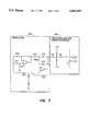
- a sensor 176 designed to minimize the effect of electrostatic dischargesis shown in FIG. 3.
- Sensor 176is similar to sensor 80 except that sensor 176 also includes a power source protector 180 and an amplifier protector 190. It should be understood that the inclusion of either the power source protector 180 or the amplifier protector 190 may be sufficient to overcome the aforementioned problems with electrostatic discharges on sensors of the subject invention.
- the power source protector 180 and the amplifier protector 190may take on any suitable form whereby the electrostatic discharge may be absorbed within the protectors 180 and 190 and not permitted to progress to other components of the sensor 176.
- the power source protector 180 and the amplifier protector 190may have similar or different configurations.
- Amplifier protector 190primarily serves the purpose of protecting electrical amplifier 106 and avoiding spiked signals which would affect the effectiveness of comparator 132.
- Power source protector 180primarily serves the purpose of protecting power source 100.
- a suitable circuitry for power source protector 180will now be described.
- a suitable amplifier protector 190may utilize the circuitry identical to that of that described for power source protector 180.
- Power source 100is electrically connected to power source protector 180 by means of conduit 192.
- Conduit 192is electrically connected to resistor R2.
- Resistor R2is electrically connected to first diode D1 and second diode D2.
- Diodes D1 and D2are also connected to ground.
- the diodes D1 and D2have two operating modes; a first low impedance mode when the voltage at the diodes is greater than a predetermined level of approximately +/-15 volts and a second high impedance mode when the voltage at the diodes is less than a predetermined level of approximately +/-15 volts.
- the diodes D1 and D2limit the voltage going through the power source protector 180 to a low level such as approximately +/-15 volts. Likewise the diodes D1 and D2 absorb most of the current.
- the diodes D1 and D2are further electrically connected to a second resistor R3. Resistor R3 serves to limit the current associated with electrostatic discharge spikes from electrode 94.
- Inductor I1is electrically connected to resistor R3.
- Inductor I1serves to spikes impede the flow of current from voltage spike caused by electrostatic discharges from electrode 94.
- Inductor I1is electrically connected by means of conduit 198 to the signal electrode 94.
- an exemplary circuit for the amplifier protector 190may be identical to that of signal electrical protector 180.
- Power from the power source 100enter through the conduit 192 into the power source protector 180.
- the electrostatic discharges having a voltage greater than a predetermined level such as 0.60 voltsare absorbed by the diodes D1 and D2.
- Poweris then transferred through conduit 198 to the signal electrode 94.
- the induced current 104is received by the sense electrode 96 and transmitted by way of conduit 199 to amplifier protector 190. Any significant electrostatic discharge current spike received at the amplifier protector 190 is absorbed by amplifier diodes D3 and D4.
- the induced current 104 from the sense electrode 96is transferred through the amplifier protector 190 and is electrically transferred by conduit 200 to electrical amplifier 106.
- Electrical amplifier 106transfers output signal 110 by means of electrical conduit 124 to rectifier 122.
- Rectifier 122rectifies the output signal 110 and converts it into its average d.c. voltage 126 which is transferred by means of electrical conduit 130 to the comparator 132.
- the comparator 132transmits a high voltage signal 136 a bottle full condition is indicated and when the comparator 132 transmits a low voltage signal 140 a bottle not full condition is indicated.
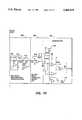
- FIG. 4An example of such failsafe logic is shown in FIG. 4.
- d.c. voltage 126is compared to the maximum voltage 201. If voltage 126 is greater than the maximum voltage 201, route 204 is taken and a bottle full block 206 is reached. If voltage 132 is less than and equal to the maximum voltage 201, route 208 is taken and block 210 is reached.
- voltage 123is compared to the minimum voltage 203. If voltage 132 is less than the minimum voltage 203, route 212 is taken and bottle full block 206 is reached. If voltage 132 is greater than or equal to the minimum voltage 203, route 214 is taken and block 216 bottle empty is reached.
- the failsafe logic as shown in FIG. 4may be accomplished by any suitable electrical circuitry, one such circuitry shown in comparator 280 of FIG. 10.
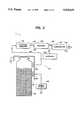
- the induced current electrical amplifier 106 of FIG. 1, the circuit protectors 180 and 190 of FIG. 3, and the failsafe logic comparator of FIG. 4may all be incorporated in a sensor 218 as shown in FIG. 5.
- Oscillator 220sends out signals 222 to electrical conduit 224 to the ESD protection circuit 226.
- the ESD protection circuit 226serves as a primary protection against damage to electrical components and reduces the effect of electrostatic discharge noise on the output.
- Signal 222 from the ESD protection 226travels through conduit 228 to signal electrode 230.
- Waste bottle 232is located adjacent the signal electrode 230.
- Signal 222induces induced current 234 which is received at sense electrode 236. Induced current 234 then travels through electrical conduit 238 to ESD protection circuit 240.
- ESD protection circuit 240protects the electrical components from electrostatic discharge at the sense electrode 236 and reduces the effect of electrostatic discharge noise on the output. Induced current 234 from the ESD protection circuit 240 travels through electrical conduit 24
- Amplifier area 243includes a first sense amplifier and low pass filter circuit 244.
- First amplifier circuit 244is electrically connected by means of electrical conduit 246 to second stage amplifier filter with clipping circuit 250.
- the sense amp and low pass filter circuit 244serves to maintain the sense electrode 236 at a low voltage approximating a virtual ground and thus define the voltage across the electrodes 230 and 236 to be the oscillating voltage.
- the virtual groundminimizes the capacitive coupling effects or impedance effects to the environment.
- the low pass filter portion of the sense amplifier circuit 244filters out high frequency signals which are typically the result of system noise including electrostatic discharges.
- the second stage amplifier and clipping circuit 250 filterprovides additional gain.
- the second stage circuit 250further filters out high frequency and low frequency noise.
- the clipping feature of the second stage circuit 250further limits the output of the second stage circuit 250 to approximately one volt. Applicants have found that the voltage at conduit 246 is normally on the order of about 300 millivolts. Without the clipping feature, the output from the second stage amplifier 250 might spike as high as 15 volts. Frequent spikes could cause the output to rise. Further, the clipping feature maintains the output of the amplifier area 243 in a linear region which likely provides a faster recovery.
- Signal 234travels via electrical conduit 252 to band pass filter 254, whose peak response is preferably designed to be the frequency of the oscillator 220.
- the signal 234 from the band pass filter 254travels via electrical conduit 256 to full wave rectifier with low pass filter 258.
- the band pass filter 254provides more filtering at any desired gain. The filtering from filter 254 is needed because the full wave rectifier 258 tends to convert the amplitude of the strongest frequency component into a d.c. voltage. If a noise source had more amplitude than the signal at the conduit 256, the d.c. output at the rectifier 258 would tend to reflect the noise components amplitude.
- the rectifier with low pass filter 258rectifies the incoming signal and passes low frequencies thereof.
- the output of the rectifier with filter 258is essentially a d.c. voltage signal 260.
- the signal 260is approximately equal to the average value of the input. D.C. voltage signal 260 from full wave rectifier 258 travels via conduit 262 to d.c. amplifier with adjustment potentiometer 264.
- the d.c. amplifier 264provides an adjustable d.c. gain so that the empty bottle output can be set to a predetermined level, for example, 2.15 volts independent of nominal component values.
- the d.c. amplifier 264produces amplified d.c. voltage signal 266.
- Reference voltage circuit 268provides bottle low failsafe threshold voltage 270 (approximately 1.5 volts).
- Amplified d.c. voltage signal 266is sent via conduit 272 to comparator 280.
- Comparator 280provides bottle full fixed threshold voltage 269 (approximately 2.7 volts).
- Low failsafe threshold voltage 270is sent via conduit 276 to comparator 280.
- Sensor digital output signal 282is generated by comparator 280.
- the comparator 280controls the sensor output signal 282.
- the signal 282is set high if the input signal is above the full threshold voltage 269 or below the low threshold voltage 270. During most situations where the circuit would be non-operational, such as disconnected harness, etc., the output would drop below the low threshold voltage 270 causing the sensor 218 to indicate a bottle full thus preventing the machine from running and overfilling the bottle.
- the failure modes covered by this circuitmay include the loss of +15 volts, the loss of -15 volts, the loss of signal, the harness being disconnected, the failure of sensor circuit characterized by low input signal, and any failure causing input signal to drop below 1.5 volts. Utilizing the comparator 280 of a type having an open collector output and defining output signal 282 high when the signal 266 is below 1.5 volts, assures proper operation when the +15 volt signal is lost.
- the power supply for oscillator 220may include power supply circuit 290 as shown in FIG. 6A.
- the amplifiers used in the amplifier area 243, band pass filter 254, full wave rectifier 258, and d.c. amplifier 264may utilize conditioning circuit 292 as shown in FIG. 6B.
- An embodiment of reference voltage circuit 268, utilized to provide reference voltages for comparator 280is shown in FIG. 6C.
- a table of exemplary circuit component values for reference voltage circuit 268, power supply conditioning circuit 290, and power source conditioning circuit 292are as follows:
- FIG. 7shows exemplary circuitry for oscillator 222 and ESD protection circuit 226.
- a table of exemplary circuit component values for oscillator 222 and ESD protection circuit 226are as follows:
- FIG. 9illustrates exemplary circuitry for ESD protection circuit 240, electrical amplifier area 243, including sense amplifier 244 and second stage amplifier 250, and band pass filter 254.
- a table of exemplary circuit component values for ESD protection circuit 240, sense amplifier 244, second stage amplifier 250, and band pass filter 254are as follows:
- FIG. 10illustrates exemplary circuitry for full wave rectifier 258, d.c. amplifier 264, and comparator 280.
- a table of exemplary circuit component values for full wave rectifier 258, d.c. amplifier 264, and comparator 280are as follows:
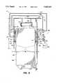
- Waste bottle 232is typically located within the cleaning unit F and preferably between cleaning unit frame 300.
- the cleaning unit frame 300is typically made of durable materials such as steel stampings and is preferably grounded.
- the waste bottle 232is located between left and right frame members 302 and 304, respectively, of the frame 300.
- a lip 306 at the upper portion of the waste bottle 232is supported by bracket 310 which is connected to the frame 300.
- the lip 306 of the bottle 232slidably fits within the bracket 310 to properly align the bottle 232 within the frame 300.
- a signal electrode bracket 312is fixedly attached to the left frame member 302 by any suitable means such as welding.
- the bracket 312may alternatively be a portion of left frame members 302.
- a signal electrode backing plate 314is fixedly attached to the sensor bracket 312 by any suitable means such as rivets 316.
- the signal electrode backing plate 314may be made of any suitable non-electrically conductive material such as an electrical circuit board.
- the signal electrode 230is located against the signal electrode backing plate 314 between the backing plate 314 and the bracket 312.
- the signal electrode 230may have any suitable shape, but applicants have found that a circular electrode with a diameter of approximately two inches is suitable for the practice of the invention.
- the signal electrode 230is constructed of an electrically conductive material.
- a sense electrode bracket 320is fixedly attached to the right frame member 304.
- the bracket 320may be a separate item or an integral part of right frame member 304.
- a sense electrode backing plate 322is fixedly attached to the sense electrode bracket 320 by any suitable means such as rivets 316.
- Sense electrode 236is located against the sense electrode backing plate 322 between the sense electrode backing plate 322 and the sense electrode bracket 320.
- the sense electrode 236is preferably similar to the signal electrode 230 with a two inch diameter round shape.
- the sense electrode 236is preferably constructed of an electrically conductive material.
- Frame vertical members 302 and 304serve as frame back plates to make the electrodes 230 and 236, respectively, insensitive to objects behind the electrodes. Back plates 302 and 304 are therefore preferably electrically conductive.
- the positioning of the electrodes 230 and 236 relative to the waste bottle 232 as well as relative to the cleaning unit frame 300is important.
- the width M of waste toner bottle 232is important and have found that the addition of reinforcing ribs 324 within the bottle 232 serves to stabilize the dimension M when the interior of the bottle 232 is subjected to a vacuum.
- the distance between the electrodes 230 and 236 and the bottle 232generally referred to as dimension K is important. Increasing dimension K decreases the signal.
- the dimension Kshould be zero, but such a dimension is impossible due to tolerances between the bottle 232 and the frame 300.
- Applicantshave found that a dimension of 4.4 millimeters for K to be adequate.
- dimension Gis important. Applicants have found that increasing dimension G increases the signal, but might make the signal less sensitive to the height of the toner in the bottle. Applicants have further found that a dimension G of 8.4 millimeters to be acceptable.
- Applicantshave further found that extending the frame back plates 302 and 304, respectively, below the electrodes 230 and 236, respectively, makes the sensor 220 less sensitive to conditions outside the electrodes 230 and 236.
- dimension Hthe dimension between the top of the electrodes 230 and 236 to top member 325 of the frame 300, generally referred to as dimension H to be important to the operation of the sensor 220. Decreasing the dimension H decreases the signal.
- a dimension of Hof as little as 2.0 inches to be acceptable.
- the circuitry of FIGS. 6, 7 and 9,may be combined onto a single electronic board 326.
- the circuit board 326is preferably mounted along frame back plate 304 adjacent the sense electrode 322 to minimize unwanted signals.
- Circuit board 326is connected to power source 330 by means of electrical conduit 332 at connector 334 to power supply circuit 290.
- the power source 330is preferably a +15 volt/-15 volt direct current source and may be provided by a transformer (not shown).
- Sense electrode 236is electrically connected via conduit 336 at connector 340 to circuit protector circuit 240.
- Signal electrode 230is connected via conduit 342 to circuit board 326 at connector 344 to ESD protection circuit 226.
- Backing plates 304 and 306are preferably grounded to the frame 300 and to each other via electrical conduit 346. It should be appreciated that any other suitable method of grounding the plates 304 and 306 may be used.
- circuit board 326may be utilized to measure toner waste bottle waste toner height
- the circuit board 326may equally be used to measure the height of the contents of any other electrically non-conductive container within the copying or printing machine.
- sense circuit 402having an electronic circuit similar to that of circuit board 326 of FIG. 8, may be electrically connected to a control box 404 via conduit 406.
- Power supply 410is electrically connected by way of electrical conduit 412 to signal electrodes 412, 416, 418 and 420, respectively, for toner waste bottle 422, fuser oil bottle 424, developer waste bottle 426, and carrier waste bottle 430, respectively.
- Toner sense electrode 432, fuser oil bottle sense electrode 434, developer waste bottle sense electrode 436, and carrier waste bottle sense electrode 440are electrically connected to the control box 404.
- the line capacitance of the sense electrodes 432, 434, 436 and 440should be approximately under 100 Pf and conduits 406 and 412 should be shielded cables.
- Control box 404may selectively sense the signal from toner waste bottle 422, fuser oil bottle 424, developer waste bottle 426, or carrier waste bottle 430.
- the same sensor 402therefore, may be used to measure the level in the toner waste bottle 422, fuser oil bottle 424, developer waste bottle 426, or the carrier waste bottle 430.
- the same sensor 402may be used to measure the level of contents of any of a number of containers. This feature may provide a very inexpensive way to measure and control the level of contents in various containers of a machine.
Landscapes
- Physics & Mathematics (AREA)
- Engineering & Computer Science (AREA)
- Power Engineering (AREA)
- General Physics & Mathematics (AREA)
- Electromagnetism (AREA)
- Thermal Sciences (AREA)
- Fluid Mechanics (AREA)
- Life Sciences & Earth Sciences (AREA)
- Environmental & Geological Engineering (AREA)
- Sustainable Development (AREA)
- Control Or Security For Electrophotography (AREA)
- Measurement Of Levels Of Liquids Or Fluent Solid Materials (AREA)
- Dry Development In Electrophotography (AREA)
- Cleaning In Electrography (AREA)
Abstract
Description
______________________________________ ELEMENT ELEMENT ELEMENT NAME NUMBER VALUE ______________________________________ CAPACITOR C2 10.0 μf CAPACITOR C3 10.0 μf CAPACITOR C4 0.01 μf CAPACITOR C5 0.01 μf CAPACITOR C6 0.1 μf CAPACITOR C7 0.01 μf CAPACITOR C8 0.01 μf CAPACITOR C9 0.01 μf CAPACITOR C10 0.01 μf CAPACITOR C11 0.01 μf CAPACITOR C12 0.01 μf CAPACITOR C13 0.01 μf RESISTOR R6 10.0 RESISTOR R7 10.0 RESISTOR R8 1.62K RESISTOR R9 3.83K RESISTOR R10 1.0K ______________________________________
______________________________________ ELEMENT ELEMENT ELEMENT NAME NUMBER VALUE ______________________________________CAPACITOR C14 220Pf CAPACITOR C15 100Pf CAPACITOR C16 12 Pf CAPACITOR C17 47 Pf RESISTOR R2 49.9K RESISTOR R3 49.9K RESISTOR R11 110K RESISTOR R12 221K RESISTOR R13 2.0K RESISTOR R14 100K RESISTOR R15 4.99K ______________________________________
______________________________________ ELEMENT ELEMENT ELEMENT NAME NUMBER VALUE ______________________________________ CAPACITOR C1 2 PF CAPACITOR C18 3300PF CAPACITOR C19 220 PF CAPACITOR C20 0.01 μf CAPACITOR C21 0.01 μf RESISTOR R1 4.99M RESISTOR R4 49.9K RESISTOR R5 49.9K RESISTOR R16 10K RESISTOR R17 47.5K RESISTOR R18 2.57K RESISTOR R19 549 RESISTOR R20 5.11K ______________________________________
______________________________________ ELEMENT ELEMENT ELEMENT NAME NUMBER VALUE ______________________________________ CAPACITOR C22 3 PF CAPACITOR C23 10.0 μf RESISTOR R21 20K RESISTOR R22 20K RESISTOR R23 20K RESISTOR R24 10K RESISTOR R25 1.0K RESISTOR R26 54.9K RESISTOR R27 3.83K RESISTOR R28 19.1K RESISTOR R29 20K RESISTOR R30 10K RESISTOR R31 12.1K RESISTOR R32 10K RESISTOR R33 2.2K ______________________________________
Claims (17)
Priority Applications (1)
| Application Number | Priority Date | Filing Date | Title |
|---|---|---|---|
| US08/289,981US5465619A (en) | 1993-09-08 | 1994-08-12 | Capacitive sensor |
Applications Claiming Priority (2)
| Application Number | Priority Date | Filing Date | Title |
|---|---|---|---|
| US11807793A | 1993-09-08 | 1993-09-08 | |
| US08/289,981US5465619A (en) | 1993-09-08 | 1994-08-12 | Capacitive sensor |
Related Parent Applications (1)
| Application Number | Title | Priority Date | Filing Date |
|---|---|---|---|
| US11807793AContinuation | 1993-09-08 | 1993-09-08 |
Publications (1)
| Publication Number | Publication Date |
|---|---|
| US5465619Atrue US5465619A (en) | 1995-11-14 |
Family
ID=22376397
Family Applications (1)
| Application Number | Title | Priority Date | Filing Date |
|---|---|---|---|
| US08/289,981Expired - LifetimeUS5465619A (en) | 1993-09-08 | 1994-08-12 | Capacitive sensor |
Country Status (3)
| Country | Link |
|---|---|
| US (1) | US5465619A (en) |
| JP (1) | JPH0792802A (en) |
| CA (1) | CA2128676C (en) |
Cited By (98)
| Publication number | Priority date | Publication date | Assignee | Title |
|---|---|---|---|---|
| US5582798A (en)* | 1995-02-23 | 1996-12-10 | Cyberlab Inc. | Volume sensing device |
| US5735167A (en)* | 1995-06-21 | 1998-04-07 | Instrumentarium Oy | Method and arrangement for measuring liquid level |
| GB2323671A (en)* | 1997-03-27 | 1998-09-30 | Eastman Kodak Co | Vessel contents sensor |
| FR2765329A1 (en)* | 1997-06-27 | 1998-12-31 | Canon Kk | Device for determining the quantity of ink in a printer having several reservoirs containing inks of different colours. |
| GB2329021A (en)* | 1997-09-05 | 1999-03-10 | Assembled Supplies | Fluid level monitor |
| US5933657A (en)* | 1995-08-29 | 1999-08-03 | Eastman Kodak Company | Making of film scrolls for prewind cameras |
| US5987269A (en)* | 1998-02-13 | 1999-11-16 | Hewlett-Packard Company | Toner quantity measuring technique in an electrophotographic printer |
| US5995778A (en)* | 1997-08-08 | 1999-11-30 | Nec Corporation | Apparatus and method for detecting toner density in a liquid developer |
| US6089688A (en)* | 1997-06-27 | 2000-07-18 | Canon Kabushiki Kaisha | Method and device for monitoring the consumption of a product, such as an ink, contained in a reservoir |
| US6183054B1 (en)* | 1997-06-27 | 2001-02-06 | Canon Kabushiki Kaisha | Method and device for determining the quantities of consumable products contained in reservoirs grouped together next to one another and document printing device using this method |
| WO2001029500A3 (en)* | 1999-10-22 | 2001-06-21 | Bently Nevada Corp | A digital eddy current proximity system: apparatus and method |
| US6254212B1 (en)* | 1996-01-22 | 2001-07-03 | Canon Kabushiki Kaisha | Method and device for determining the quantity of product present in a reservoir, notably that of ink present in an image forming device |
| US6293144B1 (en)* | 1997-06-27 | 2001-09-25 | Canon Kabushiki Kaisha | Method and device for monitoring the consumption of a product, for example a printing ink, using a low-pass filter |
| EP1143305A1 (en)* | 2000-04-06 | 2001-10-10 | Canon Kabushiki Kaisha | Developing device, process cartridge, image forming apparatus and a method for determining the remaining amount of developer |
| US6325477B1 (en)* | 1997-01-31 | 2001-12-04 | Canon Kabushiki Kaisha | Method and device for determining the quantity of product present in a reservoir, a product reservoir and a device for processing electrical signals intended for such a determination device |
| US6415112B1 (en) | 1998-11-13 | 2002-07-02 | Canon Kabushiki Kaisha | Toner remaining amount detecting device, toner remaining amount detecting method, process cartridge and electrophotographic image forming apparatus |
| US6431670B1 (en)* | 2000-02-14 | 2002-08-13 | Hewlett-Packard Company | Ink level sensing method and apparatus |
| US6472887B1 (en) | 2000-06-28 | 2002-10-29 | Hewlett-Packard Company | Capacitive sensor for sensing the amount of material in a container |
| US6501915B2 (en)* | 2000-01-13 | 2002-12-31 | Canon Kabushiki Kaisha | Image forming apparatus having detection electrode outside developing thereof |
| US6546795B1 (en)* | 2001-11-13 | 2003-04-15 | Mitsubishi Electric Research Laboratories, Inc. | Wireless liquid level sensing system and method |
| US6580881B2 (en) | 2001-10-04 | 2003-06-17 | Lexmark International, Inc. | Method of detecting waste toner in a container of an image forming apparatus |
| US6670817B2 (en)* | 2001-06-07 | 2003-12-30 | Heidelberger Druckmaschinen Ag | Capacitive toner level detection |
| EP1055976A3 (en)* | 1999-05-27 | 2004-02-25 | Canon Kabushiki Kaisha | Developping device, process cartidge and electrophotographic image forming apparatus |
| EP1055975A3 (en)* | 1999-05-27 | 2004-02-25 | Canon Kabushiki Kaisha | Developing device, process cartridge and electrophotographic image forming apparatus |
| US6731885B2 (en)* | 2001-06-29 | 2004-05-04 | Heidelberger Druckmaschinen Ag | Capacitive probe toner level detector assembly |
| US20040088269A1 (en)* | 2002-10-31 | 2004-05-06 | Davis Susan M.F. | Capacitance sensing to estimate weight ranges for items being transferred by a conveyor system |
| US20040144799A1 (en)* | 2003-01-24 | 2004-07-29 | Baxter International Inc. | Liquid dispenser and flexible bag therefor |
| US6769231B2 (en) | 2001-07-19 | 2004-08-03 | Baxter International, Inc. | Apparatus, method and flexible bag for use in manufacturing |
| US20040188999A1 (en)* | 2003-03-31 | 2004-09-30 | Samsung Gwang Ju Electronics Co., Ltd. | Compressor and method of connecting pipe to the same |
| US20050010302A1 (en)* | 2003-07-11 | 2005-01-13 | Terry Dietz | Telemetric tibial tray |
| US20050010301A1 (en)* | 2003-07-11 | 2005-01-13 | Disilvestro Mark R. | In vivo joint space measurement device and method |
| US20050010300A1 (en)* | 2003-07-11 | 2005-01-13 | Disilvestro Mark R. | Orthopaedic element with self-contained data storage |
| US20050010299A1 (en)* | 2003-07-11 | 2005-01-13 | Disilvestro Mark R. | In vivo joint implant cycle counter |
| US6905314B2 (en) | 2001-10-16 | 2005-06-14 | Baxter International Inc. | Pump having flexible liner and compounding apparatus having such a pump |
| US20060038574A1 (en)* | 2004-08-23 | 2006-02-23 | Xerox Corporation | Method of detecting an arcing event and a printing machine arranged with the same |
| US7007824B2 (en) | 2003-01-24 | 2006-03-07 | Baxter International Inc. | Liquid dispenser and flexible bag therefor |
| US7061391B2 (en)* | 2001-10-17 | 2006-06-13 | International Business Machines Corporation | Method, system, and program for monitoring a consumable resource used by a system |
| US20060160171A1 (en)* | 2004-12-27 | 2006-07-20 | Becton, Dickinson And Company | Detection method and apparatus for detecting microbial growth |
| US20060285899A1 (en)* | 2005-06-20 | 2006-12-21 | Xerox Corporation | Waste toner vibration device |
| US20070069680A1 (en)* | 2004-01-28 | 2007-03-29 | Landry Gregg W | Debris Sensor for Cleaning Apparatus |
| US20070292163A1 (en)* | 2006-06-19 | 2007-12-20 | Xerox Corporation | Development sub-system in-line cleaning system |
| US20070292164A1 (en)* | 2006-06-19 | 2007-12-20 | Xerox Corporation | Development sub-system in-line cleaning system |
| US20080069576A1 (en)* | 2006-09-14 | 2008-03-20 | Paul Etter | Capacitive Toner Level Sensor and Methods of Use |
| US20080106753A1 (en)* | 2006-11-07 | 2008-05-08 | Xerox | Partial electrical discharge system and method |
| CN100426602C (en)* | 2003-09-01 | 2008-10-15 | 恩德莱斯和豪瑟尔两合公司 | Field device for determining and/or monitoring a process variable |
| US20090052918A1 (en)* | 2004-09-30 | 2009-02-26 | Canon Kabushiki Kaisha | Image forming apparatus and method of detecting amount of residual developer |
| US20090158841A1 (en)* | 2005-11-30 | 2009-06-25 | Frank Winkens | Sensor for the contactless detection of the level of a liquid and adhering high-conductivity meduim, especially blood, through a non-metal wall of a container and corresponding method |
| US20090263146A1 (en)* | 2008-04-16 | 2009-10-22 | Xerox Corporation | Toner level sensing |
| WO2011077187A1 (en) | 2009-12-22 | 2011-06-30 | Cefriel - Societa' Consortile A Responsabilita' Limitata | Measuring device, container means and system for monitoring and managing container means |
| US20110259098A1 (en)* | 2008-06-03 | 2011-10-27 | Young-Un Park | Level sensing apparatus |
| US20120031523A1 (en)* | 2009-01-08 | 2012-02-09 | Electrolux Home Products Corporation N.V. | Method for dispensing a liquid into a container and related dispenser |
| US8239992B2 (en) | 2007-05-09 | 2012-08-14 | Irobot Corporation | Compact autonomous coverage robot |
| US8256869B2 (en) | 2009-11-02 | 2012-09-04 | Xerox Corporation | Capacitive drop mass measurement system |
| US8368339B2 (en) | 2001-01-24 | 2013-02-05 | Irobot Corporation | Robot confinement |
| US8374721B2 (en) | 2005-12-02 | 2013-02-12 | Irobot Corporation | Robot system |
| US8380350B2 (en) | 2005-12-02 | 2013-02-19 | Irobot Corporation | Autonomous coverage robot navigation system |
| US8386081B2 (en) | 2002-09-13 | 2013-02-26 | Irobot Corporation | Navigational control system for a robotic device |
| US8390251B2 (en) | 2004-01-21 | 2013-03-05 | Irobot Corporation | Autonomous robot auto-docking and energy management systems and methods |
| US8392021B2 (en) | 2005-02-18 | 2013-03-05 | Irobot Corporation | Autonomous surface cleaning robot for wet cleaning |
| US8387193B2 (en) | 2005-02-18 | 2013-03-05 | Irobot Corporation | Autonomous surface cleaning robot for wet and dry cleaning |
| US8396592B2 (en) | 2001-06-12 | 2013-03-12 | Irobot Corporation | Method and system for multi-mode coverage for an autonomous robot |
| US8412377B2 (en) | 2000-01-24 | 2013-04-02 | Irobot Corporation | Obstacle following sensor scheme for a mobile robot |
| US8417383B2 (en) | 2006-05-31 | 2013-04-09 | Irobot Corporation | Detecting robot stasis |
| US8418303B2 (en) | 2006-05-19 | 2013-04-16 | Irobot Corporation | Cleaning robot roller processing |
| US8428778B2 (en) | 2002-09-13 | 2013-04-23 | Irobot Corporation | Navigational control system for a robotic device |
| US8463438B2 (en) | 2001-06-12 | 2013-06-11 | Irobot Corporation | Method and system for multi-mode coverage for an autonomous robot |
| US8474090B2 (en) | 2002-01-03 | 2013-07-02 | Irobot Corporation | Autonomous floor-cleaning robot |
| US8515578B2 (en) | 2002-09-13 | 2013-08-20 | Irobot Corporation | Navigational control system for a robotic device |
| US8584305B2 (en) | 2005-12-02 | 2013-11-19 | Irobot Corporation | Modular robot |
| US8594840B1 (en) | 2004-07-07 | 2013-11-26 | Irobot Corporation | Celestial navigation system for an autonomous robot |
| US8600553B2 (en) | 2005-12-02 | 2013-12-03 | Irobot Corporation | Coverage robot mobility |
| US8739355B2 (en) | 2005-02-18 | 2014-06-03 | Irobot Corporation | Autonomous surface cleaning robot for dry cleaning |
| US8780342B2 (en) | 2004-03-29 | 2014-07-15 | Irobot Corporation | Methods and apparatus for position estimation using reflected light sources |
| US8788092B2 (en) | 2000-01-24 | 2014-07-22 | Irobot Corporation | Obstacle following sensor scheme for a mobile robot |
| US8800107B2 (en) | 2010-02-16 | 2014-08-12 | Irobot Corporation | Vacuum brush |
| US8930023B2 (en) | 2009-11-06 | 2015-01-06 | Irobot Corporation | Localization by learning of wave-signal distributions |
| US8972052B2 (en) | 2004-07-07 | 2015-03-03 | Irobot Corporation | Celestial navigation system for an autonomous vehicle |
| US9008835B2 (en) | 2004-06-24 | 2015-04-14 | Irobot Corporation | Remote control scheduler and method for autonomous robotic device |
| US9320398B2 (en) | 2005-12-02 | 2016-04-26 | Irobot Corporation | Autonomous coverage robots |
| TWI586104B (en)* | 2011-05-04 | 2017-06-01 | 微晶片科技德國公司 | A capacitive sensor device as well as a method for operating an input device |
| DE10309769B4 (en)* | 2002-03-08 | 2017-10-05 | Ust Umweltsensortechnik Gmbh | Arrangement for determining state variables for liquids in a closed non-metallic container |
| US9789697B1 (en)* | 2016-07-27 | 2017-10-17 | Xerox Corporation | Fluid level sensor with combined capacitance and conductance |
| US10066564B2 (en) | 2012-06-07 | 2018-09-04 | GM Global Technology Operations LLC | Humidity determination and compensation systems and methods using an intake oxygen sensor |
| US20180341199A1 (en)* | 2017-05-24 | 2018-11-29 | Ricoh Company, Ltd. | Powder-amount detection device and image forming apparatus incorporating same |
| WO2019078843A1 (en)* | 2017-10-18 | 2019-04-25 | Hewlett-Packard Development Company, L.P. | Container for fluid |
| US20190187585A1 (en)* | 2017-12-19 | 2019-06-20 | Lexmark International, Inc. | Capacitive toner level sensor |
| NL2021069B1 (en)* | 2018-06-06 | 2019-12-11 | Heineken Supply Chain Bv | Flow detection circuit |
| US20200033752A1 (en)* | 2018-07-30 | 2020-01-30 | Tatsuya Kubo | Powder amount detector, powder supply device, and image forming apparatus incorporating same |
| EP3796092A1 (en)* | 2019-09-18 | 2021-03-24 | KYOCERA Document Solutions Inc. | Image forming apparatus |
| JP2021047281A (en)* | 2019-09-18 | 2021-03-25 | 京セラドキュメントソリューションズ株式会社 | Container mounting device and image forming apparatus |
| US11029623B2 (en)* | 2019-07-31 | 2021-06-08 | Ricoh Company, Ltd. | Powder amount detector including a pair of measuring electrodes |
| WO2021112679A3 (en)* | 2019-12-05 | 2021-08-19 | Heineken Supply Chain B.V. | Flow detection circuit |
| US11126111B2 (en)* | 2019-04-17 | 2021-09-21 | Ricoh Company, Ltd. | Toner amount detector, toner amount detection method, and non-transitory storage medium storing program |
| US11215948B2 (en)* | 2019-07-31 | 2022-01-04 | Ricoh Company, Ltd. | Powder collection device and image forming apparatus incorporating same |
| US20220221321A1 (en)* | 2021-01-13 | 2022-07-14 | Parker-Hannifin Corporation | Remote measuring liquid level sensor for intermediate bulk container applications |
| US20220283533A1 (en)* | 2021-03-08 | 2022-09-08 | Ricoh Company, Ltd. | Remaining toner amount detection device, image forming apparatus, and remaining toner amount detection method |
| RU2793146C2 (en)* | 2018-06-06 | 2023-03-29 | Хейнекен Сэпплай Чэйн Б.В. | Flow detection circuit |
| US12420555B2 (en)* | 2023-01-30 | 2025-09-23 | Seiko Epson Corporation | Liquid discharge apparatus and storage device |
Families Citing this family (6)
| Publication number | Priority date | Publication date | Assignee | Title |
|---|---|---|---|---|
| EP1016939B1 (en) | 1998-12-28 | 2006-02-01 | Canon Kabushiki Kaisha | Image developing apparatus, process cartridge, electrophotographic image forming apparatus, and development unit frame |
| JP2002031942A (en)* | 2000-07-18 | 2002-01-31 | Ricoh Co Ltd | Developer supply device and developer container |
| JP7338343B2 (en)* | 2019-09-18 | 2023-09-05 | 京セラドキュメントソリューションズ株式会社 | Container mounting device and image forming device |
| JP7342608B2 (en)* | 2019-10-24 | 2023-09-12 | 株式会社リコー | Toner remaining amount detection device, image forming device, and toner remaining amount detection method |
| JP7521200B2 (en)* | 2020-02-14 | 2024-07-24 | 京セラドキュメントソリューションズ株式会社 | Image forming device |
| JP7622561B2 (en) | 2021-06-15 | 2025-01-28 | 株式会社リコー | Toner remaining amount detection device and image forming apparatus |
Citations (28)
| Publication number | Priority date | Publication date | Assignee | Title |
|---|---|---|---|---|
| US3301056A (en)* | 1963-06-14 | 1967-01-31 | Trans Sonics Inc | Liquid measuring system |
| US3498500A (en)* | 1968-02-13 | 1970-03-03 | Xerox Corp | Level sensor |
| US3520445A (en)* | 1968-02-13 | 1970-07-14 | Xerox Corp | Dielectric level sensor |
| US3533286A (en)* | 1969-01-28 | 1970-10-13 | Trans Sonics Inc | Tank quantity gage |
| US3706980A (en)* | 1970-04-27 | 1972-12-19 | Drexelbrook Controls | Rf system for measuring the level of materials |
| US3774238A (en)* | 1971-12-09 | 1973-11-20 | Spearhead Inc | Three-terminal capacitive apparatus for remotely responding to a condition or dielectric properties of a material |
| US3801902A (en)* | 1972-07-27 | 1974-04-02 | Gull Airborne Instruments Inc | Electrical measuring apparatus employing a plurality of condition responsive devices |
| US3935739A (en)* | 1974-04-10 | 1976-02-03 | Liquidometer Corporation | Liquid level gauging apparatus |
| NL7503179A (en)* | 1975-03-18 | 1976-09-21 | Univ Erasmus | Electronic measurement of fluid quantity in vessel - capacitor formed by electrodes and fluid originates signal sequence |
| US4099167A (en)* | 1977-02-10 | 1978-07-04 | P.R. Mallory & Co. Inc. | Capacitive means for measuring the level of a liquid |
| US4133453A (en)* | 1975-12-18 | 1979-01-09 | Tokyo Shibaura Electric Co., Ltd. | Toner residual amount detecting device |
| US4313343A (en)* | 1978-07-24 | 1982-02-02 | Konishiroku Photo Industry Co., Ltd. | Apparatus for detecting remaining quantity of toner in electrophotographic copying machine |
| US4423628A (en)* | 1981-07-18 | 1984-01-03 | Richter Olaf A | Method and apparatus for monitoring the length of a liquid column |
| US4603581A (en)* | 1984-02-14 | 1986-08-05 | Nippon Soken, Inc. | Sensing apparatus |
| US4624139A (en)* | 1984-09-21 | 1986-11-25 | Berwind Corporation | Capacitance-type material level indicator |
| FR2592713A1 (en)* | 1986-01-03 | 1987-07-10 | Scheiber Roger | Electrostatic gauge allowing, by means of a single conductor externally fixed onto a non-metallic tank, the level of the contents to be measured |
| US4711561A (en)* | 1985-10-21 | 1987-12-08 | Rank Xerox Limited | Toner recovery device |
| US4749988A (en)* | 1986-11-20 | 1988-06-07 | Imtec Products, Inc. | Non-invasive liquid level sensor |
| US4757252A (en)* | 1985-10-25 | 1988-07-12 | Drexelbrook Controls, Inc. | Probe system for measuring the condition of materials |
| US4820973A (en)* | 1986-11-21 | 1989-04-11 | Alvarez Jose A | Impedance measuring system |
| US4868599A (en)* | 1986-06-02 | 1989-09-19 | Seiko Epson Corporation | Device and method for storing toner waste |
| JPH02150726A (en)* | 1988-12-01 | 1990-06-11 | Matsushita Electric Ind Co Ltd | Liquid level detection device |
| US4987776A (en)* | 1988-03-16 | 1991-01-29 | Koon Terry D | Level indicator |
| US5017909A (en)* | 1989-01-06 | 1991-05-21 | Standex International Corporation | Capacitive liquid level sensor |
| US5121631A (en)* | 1988-10-11 | 1992-06-16 | Euromart Corporation | Shielded level sensing system |
| US5132626A (en)* | 1989-05-31 | 1992-07-21 | Amoco Corporation | Electrolytic storage cell monitoring system |
| US5195010A (en)* | 1990-01-23 | 1993-03-16 | Thomson, S.A. | Electrostatic discharge voltage protection circuit for a solid state instrument |
| US5198860A (en)* | 1989-10-04 | 1993-03-30 | Canon Kabushiki Kaisha | Image forming apparatus including means for detecting amount of toner |
- 1994
- 1994-07-22CACA002128676Apatent/CA2128676C/ennot_activeExpired - Fee Related
- 1994-08-12USUS08/289,981patent/US5465619A/ennot_activeExpired - Lifetime
- 1994-08-29JPJP6203391Apatent/JPH0792802A/enactivePending
Patent Citations (28)
| Publication number | Priority date | Publication date | Assignee | Title |
|---|---|---|---|---|
| US3301056A (en)* | 1963-06-14 | 1967-01-31 | Trans Sonics Inc | Liquid measuring system |
| US3498500A (en)* | 1968-02-13 | 1970-03-03 | Xerox Corp | Level sensor |
| US3520445A (en)* | 1968-02-13 | 1970-07-14 | Xerox Corp | Dielectric level sensor |
| US3533286A (en)* | 1969-01-28 | 1970-10-13 | Trans Sonics Inc | Tank quantity gage |
| US3706980A (en)* | 1970-04-27 | 1972-12-19 | Drexelbrook Controls | Rf system for measuring the level of materials |
| US3774238A (en)* | 1971-12-09 | 1973-11-20 | Spearhead Inc | Three-terminal capacitive apparatus for remotely responding to a condition or dielectric properties of a material |
| US3801902A (en)* | 1972-07-27 | 1974-04-02 | Gull Airborne Instruments Inc | Electrical measuring apparatus employing a plurality of condition responsive devices |
| US3935739A (en)* | 1974-04-10 | 1976-02-03 | Liquidometer Corporation | Liquid level gauging apparatus |
| NL7503179A (en)* | 1975-03-18 | 1976-09-21 | Univ Erasmus | Electronic measurement of fluid quantity in vessel - capacitor formed by electrodes and fluid originates signal sequence |
| US4133453A (en)* | 1975-12-18 | 1979-01-09 | Tokyo Shibaura Electric Co., Ltd. | Toner residual amount detecting device |
| US4099167A (en)* | 1977-02-10 | 1978-07-04 | P.R. Mallory & Co. Inc. | Capacitive means for measuring the level of a liquid |
| US4313343A (en)* | 1978-07-24 | 1982-02-02 | Konishiroku Photo Industry Co., Ltd. | Apparatus for detecting remaining quantity of toner in electrophotographic copying machine |
| US4423628A (en)* | 1981-07-18 | 1984-01-03 | Richter Olaf A | Method and apparatus for monitoring the length of a liquid column |
| US4603581A (en)* | 1984-02-14 | 1986-08-05 | Nippon Soken, Inc. | Sensing apparatus |
| US4624139A (en)* | 1984-09-21 | 1986-11-25 | Berwind Corporation | Capacitance-type material level indicator |
| US4711561A (en)* | 1985-10-21 | 1987-12-08 | Rank Xerox Limited | Toner recovery device |
| US4757252A (en)* | 1985-10-25 | 1988-07-12 | Drexelbrook Controls, Inc. | Probe system for measuring the condition of materials |
| FR2592713A1 (en)* | 1986-01-03 | 1987-07-10 | Scheiber Roger | Electrostatic gauge allowing, by means of a single conductor externally fixed onto a non-metallic tank, the level of the contents to be measured |
| US4868599A (en)* | 1986-06-02 | 1989-09-19 | Seiko Epson Corporation | Device and method for storing toner waste |
| US4749988A (en)* | 1986-11-20 | 1988-06-07 | Imtec Products, Inc. | Non-invasive liquid level sensor |
| US4820973A (en)* | 1986-11-21 | 1989-04-11 | Alvarez Jose A | Impedance measuring system |
| US4987776A (en)* | 1988-03-16 | 1991-01-29 | Koon Terry D | Level indicator |
| US5121631A (en)* | 1988-10-11 | 1992-06-16 | Euromart Corporation | Shielded level sensing system |
| JPH02150726A (en)* | 1988-12-01 | 1990-06-11 | Matsushita Electric Ind Co Ltd | Liquid level detection device |
| US5017909A (en)* | 1989-01-06 | 1991-05-21 | Standex International Corporation | Capacitive liquid level sensor |
| US5132626A (en)* | 1989-05-31 | 1992-07-21 | Amoco Corporation | Electrolytic storage cell monitoring system |
| US5198860A (en)* | 1989-10-04 | 1993-03-30 | Canon Kabushiki Kaisha | Image forming apparatus including means for detecting amount of toner |
| US5195010A (en)* | 1990-01-23 | 1993-03-16 | Thomson, S.A. | Electrostatic discharge voltage protection circuit for a solid state instrument |
Non-Patent Citations (2)
| Title |
|---|
| Research Disclosure Bulletin; "Toner Level Detector"; RDB8221306; p. 482; Jan. 1982; Anonymous. |
| Research Disclosure Bulletin; Toner Level Detector ; RDB8221306; p. 482; Jan. 1982; Anonymous.* |
Cited By (226)
| Publication number | Priority date | Publication date | Assignee | Title |
|---|---|---|---|---|
| US5582798A (en)* | 1995-02-23 | 1996-12-10 | Cyberlab Inc. | Volume sensing device |
| US5735167A (en)* | 1995-06-21 | 1998-04-07 | Instrumentarium Oy | Method and arrangement for measuring liquid level |
| US5933657A (en)* | 1995-08-29 | 1999-08-03 | Eastman Kodak Company | Making of film scrolls for prewind cameras |
| US6254212B1 (en)* | 1996-01-22 | 2001-07-03 | Canon Kabushiki Kaisha | Method and device for determining the quantity of product present in a reservoir, notably that of ink present in an image forming device |
| US6325477B1 (en)* | 1997-01-31 | 2001-12-04 | Canon Kabushiki Kaisha | Method and device for determining the quantity of product present in a reservoir, a product reservoir and a device for processing electrical signals intended for such a determination device |
| GB2323671B (en)* | 1997-03-27 | 2001-03-14 | Eastman Kodak Co | Vessel contents sensor |
| GB2323671A (en)* | 1997-03-27 | 1998-09-30 | Eastman Kodak Co | Vessel contents sensor |
| US6089688A (en)* | 1997-06-27 | 2000-07-18 | Canon Kabushiki Kaisha | Method and device for monitoring the consumption of a product, such as an ink, contained in a reservoir |
| US6095629A (en)* | 1997-06-27 | 2000-08-01 | Canon Kabushiki Kaisha | Device for determining quantities of consumable products contained in reservoirs and a document printing device having several different reservoirs of pigmented products |
| US6183054B1 (en)* | 1997-06-27 | 2001-02-06 | Canon Kabushiki Kaisha | Method and device for determining the quantities of consumable products contained in reservoirs grouped together next to one another and document printing device using this method |
| US6293144B1 (en)* | 1997-06-27 | 2001-09-25 | Canon Kabushiki Kaisha | Method and device for monitoring the consumption of a product, for example a printing ink, using a low-pass filter |
| FR2765329A1 (en)* | 1997-06-27 | 1998-12-31 | Canon Kk | Device for determining the quantity of ink in a printer having several reservoirs containing inks of different colours. |
| US5995778A (en)* | 1997-08-08 | 1999-11-30 | Nec Corporation | Apparatus and method for detecting toner density in a liquid developer |
| GB2329021A (en)* | 1997-09-05 | 1999-03-10 | Assembled Supplies | Fluid level monitor |
| EP0936508A3 (en)* | 1998-02-13 | 2000-09-13 | Hewlett-Packard Company | Toner quantity measuring system |
| US5987269A (en)* | 1998-02-13 | 1999-11-16 | Hewlett-Packard Company | Toner quantity measuring technique in an electrophotographic printer |
| US6415112B1 (en) | 1998-11-13 | 2002-07-02 | Canon Kabushiki Kaisha | Toner remaining amount detecting device, toner remaining amount detecting method, process cartridge and electrophotographic image forming apparatus |
| EP1055975A3 (en)* | 1999-05-27 | 2004-02-25 | Canon Kabushiki Kaisha | Developing device, process cartridge and electrophotographic image forming apparatus |
| EP1055976A3 (en)* | 1999-05-27 | 2004-02-25 | Canon Kabushiki Kaisha | Developping device, process cartidge and electrophotographic image forming apparatus |
| US6346807B1 (en) | 1999-10-22 | 2002-02-12 | Bently Nevada Corporation | Digital eddy current proximity system: apparatus and method |
| US6819122B2 (en) | 1999-10-22 | 2004-11-16 | Bently Nevada, Llc | Method for measuring a gap between a proximity probe and a conductive target material |
| US6954062B2 (en) | 1999-10-22 | 2005-10-11 | Bently Nevada, Llc | Apparatus for determining gaps between a proximity probe and a conductive target material |
| US6919731B2 (en) | 1999-10-22 | 2005-07-19 | Bently Nevada, Llc | Method for measuring a position of a conductive target material |
| US6906532B2 (en) | 1999-10-22 | 2005-06-14 | Bently Nevada, Llc | Method for digitally measuring electrical impedance |
| US20050104579A1 (en)* | 1999-10-22 | 2005-05-19 | Slates Richard D. | Determining gaps between a proximity probe and a conductive target material |
| US20030206004A1 (en)* | 1999-10-22 | 2003-11-06 | Slates Richard D. | Digital eddy current proximity system: apparatus and method |
| US20030206002A1 (en)* | 1999-10-22 | 2003-11-06 | Slates Richard D. | Method for measuring a gap between a proximity probe and a conductive target material |
| US20030206005A1 (en)* | 1999-10-22 | 2003-11-06 | Slates Richard D. | Apparatus for determining a gap between a proximity probe component and a conductive target material |
| US20030206003A1 (en)* | 1999-10-22 | 2003-11-06 | Slates Richard D. | Method for measuring a gap between a proximity probe and a conductive target material |
| US20030206006A1 (en)* | 1999-10-22 | 2003-11-06 | Slates Richard D. | Method for measuring a gap between a proximity probe and a conductive target material |
| US20030206001A1 (en)* | 1999-10-22 | 2003-11-06 | Slates Richard D. | Method for measuring a position of a conductive target material |
| US20030210036A1 (en)* | 1999-10-22 | 2003-11-13 | Slates Richard D. | Device for digitally measuring electrical impedance |
| US20030210039A1 (en)* | 1999-10-22 | 2003-11-13 | Slates Richard D. | Method for measuring a gap between a proximity probe and a conductive target material |
| US20030214282A1 (en)* | 1999-10-22 | 2003-11-20 | Slates Richard D. | Method for measuring a gap between a proximity probe and a conductive target material |
| US20030214283A1 (en)* | 1999-10-22 | 2003-11-20 | Slates Richard D. | Digital eddy current proximity system: apparatus and method |
| US20030222639A1 (en)* | 1999-10-22 | 2003-12-04 | Slates Richard D. | Determining a dynamic gaps between a proximity probe and a conductive target material |
| US6664782B2 (en) | 1999-10-22 | 2003-12-16 | Bently Nevada, Llc | Digital eddy current proximity system: apparatus and method |
| US6861852B2 (en) | 1999-10-22 | 2005-03-01 | Bently Nevada, Llc | Method for measuring a gap between a proximity probe and a conductive target material |
| US6850078B2 (en) | 1999-10-22 | 2005-02-01 | Bently Nevada, Llc | Method for measuring a gap between a proximity probe and a conductive target material |
| US6850077B2 (en) | 1999-10-22 | 2005-02-01 | Bently Nevada, Llc | Method for measuring a characteristic of a conductive target material using a proximity probe |
| US6847217B2 (en) | 1999-10-22 | 2005-01-25 | Bently Nevada, Llc | Method for measuring a gap between a proximity probe and a conductive target material |
| US6842020B2 (en) | 1999-10-22 | 2005-01-11 | Bently Nevada, Llc | Method for measuring a gap between a proximity probe and a conductive target material |
| US6756794B2 (en) | 1999-10-22 | 2004-06-29 | Bently Nevada, Llc | Apparatus for determining a gap between a proximity probe component and a conductive target material |
| US6765395B2 (en) | 1999-10-22 | 2004-07-20 | Bently Nevada, Llc | Method for measuring a gap between a proximity probe and a conductive target material |
| WO2001029500A3 (en)* | 1999-10-22 | 2001-06-21 | Bently Nevada Corp | A digital eddy current proximity system: apparatus and method |
| US6825676B2 (en) | 1999-10-22 | 2004-11-30 | Bently Nevada, Llc | Apparatus for determining dynamic gaps between a proximity probe and a conductive target material |
| US20040176918A1 (en)* | 1999-10-22 | 2004-09-09 | Slates Richard D. | Method for digitally measuring electrical impedance |
| US6798194B2 (en) | 1999-10-22 | 2004-09-28 | Bently Nevada, Llc | Method for measuring a gap between a proximity probe and a conductive target material |
| US6501915B2 (en)* | 2000-01-13 | 2002-12-31 | Canon Kabushiki Kaisha | Image forming apparatus having detection electrode outside developing thereof |
| US8565920B2 (en) | 2000-01-24 | 2013-10-22 | Irobot Corporation | Obstacle following sensor scheme for a mobile robot |
| US8412377B2 (en) | 2000-01-24 | 2013-04-02 | Irobot Corporation | Obstacle following sensor scheme for a mobile robot |
| US8761935B2 (en) | 2000-01-24 | 2014-06-24 | Irobot Corporation | Obstacle following sensor scheme for a mobile robot |
| US8478442B2 (en) | 2000-01-24 | 2013-07-02 | Irobot Corporation | Obstacle following sensor scheme for a mobile robot |
| US9446521B2 (en) | 2000-01-24 | 2016-09-20 | Irobot Corporation | Obstacle following sensor scheme for a mobile robot |
| US8788092B2 (en) | 2000-01-24 | 2014-07-22 | Irobot Corporation | Obstacle following sensor scheme for a mobile robot |
| US6431670B1 (en)* | 2000-02-14 | 2002-08-13 | Hewlett-Packard Company | Ink level sensing method and apparatus |
| US9144361B2 (en) | 2000-04-04 | 2015-09-29 | Irobot Corporation | Debris sensor for cleaning apparatus |
| US6892035B2 (en) | 2000-04-06 | 2005-05-10 | Canon Kabushiki Kaisha | Developing device, a process cartridge, and an electrophotographic image forming apparatus for detecting an amount of developer |
| EP1143305A1 (en)* | 2000-04-06 | 2001-10-10 | Canon Kabushiki Kaisha | Developing device, process cartridge, image forming apparatus and a method for determining the remaining amount of developer |
| US6472887B1 (en) | 2000-06-28 | 2002-10-29 | Hewlett-Packard Company | Capacitive sensor for sensing the amount of material in a container |
| US9038233B2 (en) | 2001-01-24 | 2015-05-26 | Irobot Corporation | Autonomous floor-cleaning robot |
| US8686679B2 (en) | 2001-01-24 | 2014-04-01 | Irobot Corporation | Robot confinement |
| US9167946B2 (en) | 2001-01-24 | 2015-10-27 | Irobot Corporation | Autonomous floor cleaning robot |
| US9622635B2 (en) | 2001-01-24 | 2017-04-18 | Irobot Corporation | Autonomous floor-cleaning robot |
| US9582005B2 (en) | 2001-01-24 | 2017-02-28 | Irobot Corporation | Robot confinement |
| US8368339B2 (en) | 2001-01-24 | 2013-02-05 | Irobot Corporation | Robot confinement |
| US6670817B2 (en)* | 2001-06-07 | 2003-12-30 | Heidelberger Druckmaschinen Ag | Capacitive toner level detection |
| US8396592B2 (en) | 2001-06-12 | 2013-03-12 | Irobot Corporation | Method and system for multi-mode coverage for an autonomous robot |
| US9104204B2 (en) | 2001-06-12 | 2015-08-11 | Irobot Corporation | Method and system for multi-mode coverage for an autonomous robot |
| US8463438B2 (en) | 2001-06-12 | 2013-06-11 | Irobot Corporation | Method and system for multi-mode coverage for an autonomous robot |
| US6731885B2 (en)* | 2001-06-29 | 2004-05-04 | Heidelberger Druckmaschinen Ag | Capacitive probe toner level detector assembly |
| US6769231B2 (en) | 2001-07-19 | 2004-08-03 | Baxter International, Inc. | Apparatus, method and flexible bag for use in manufacturing |
| US6580881B2 (en) | 2001-10-04 | 2003-06-17 | Lexmark International, Inc. | Method of detecting waste toner in a container of an image forming apparatus |
| US6905314B2 (en) | 2001-10-16 | 2005-06-14 | Baxter International Inc. | Pump having flexible liner and compounding apparatus having such a pump |
| US7061391B2 (en)* | 2001-10-17 | 2006-06-13 | International Business Machines Corporation | Method, system, and program for monitoring a consumable resource used by a system |
| US6546795B1 (en)* | 2001-11-13 | 2003-04-15 | Mitsubishi Electric Research Laboratories, Inc. | Wireless liquid level sensing system and method |
| US8516651B2 (en) | 2002-01-03 | 2013-08-27 | Irobot Corporation | Autonomous floor-cleaning robot |
| US8474090B2 (en) | 2002-01-03 | 2013-07-02 | Irobot Corporation | Autonomous floor-cleaning robot |
| US9128486B2 (en) | 2002-01-24 | 2015-09-08 | Irobot Corporation | Navigational control system for a robotic device |
| DE10309769B4 (en)* | 2002-03-08 | 2017-10-05 | Ust Umweltsensortechnik Gmbh | Arrangement for determining state variables for liquids in a closed non-metallic container |
| US8781626B2 (en) | 2002-09-13 | 2014-07-15 | Irobot Corporation | Navigational control system for a robotic device |
| US8386081B2 (en) | 2002-09-13 | 2013-02-26 | Irobot Corporation | Navigational control system for a robotic device |
| US8428778B2 (en) | 2002-09-13 | 2013-04-23 | Irobot Corporation | Navigational control system for a robotic device |
| US8515578B2 (en) | 2002-09-13 | 2013-08-20 | Irobot Corporation | Navigational control system for a robotic device |
| US9949608B2 (en) | 2002-09-13 | 2018-04-24 | Irobot Corporation | Navigational control system for a robotic device |
| US8793020B2 (en) | 2002-09-13 | 2014-07-29 | Irobot Corporation | Navigational control system for a robotic device |
| US20040088269A1 (en)* | 2002-10-31 | 2004-05-06 | Davis Susan M.F. | Capacitance sensing to estimate weight ranges for items being transferred by a conveyor system |
| US7007824B2 (en) | 2003-01-24 | 2006-03-07 | Baxter International Inc. | Liquid dispenser and flexible bag therefor |
| US7237691B2 (en) | 2003-01-24 | 2007-07-03 | Baxter International Inc. | Flexible bag for fluent material dispenser |
| US20040144799A1 (en)* | 2003-01-24 | 2004-07-29 | Baxter International Inc. | Liquid dispenser and flexible bag therefor |
| US20040188999A1 (en)* | 2003-03-31 | 2004-09-30 | Samsung Gwang Ju Electronics Co., Ltd. | Compressor and method of connecting pipe to the same |
| US20050010301A1 (en)* | 2003-07-11 | 2005-01-13 | Disilvestro Mark R. | In vivo joint space measurement device and method |
| US7470288B2 (en) | 2003-07-11 | 2008-12-30 | Depuy Products, Inc. | Telemetric tibial tray |
| US20050010299A1 (en)* | 2003-07-11 | 2005-01-13 | Disilvestro Mark R. | In vivo joint implant cycle counter |
| US7347874B2 (en) | 2003-07-11 | 2008-03-25 | Depuy Products, Inc. | In vivo joint implant cycle counter |
| US20050010300A1 (en)* | 2003-07-11 | 2005-01-13 | Disilvestro Mark R. | Orthopaedic element with self-contained data storage |
| US7704282B2 (en) | 2003-07-11 | 2010-04-27 | Depuy Products, Inc. | Orthopaedic element with self-contained data storage |
| US20050010302A1 (en)* | 2003-07-11 | 2005-01-13 | Terry Dietz | Telemetric tibial tray |
| US7195645B2 (en) | 2003-07-11 | 2007-03-27 | Depuy Products, Inc. | In vivo joint space measurement device and method |
| CN100426602C (en)* | 2003-09-01 | 2008-10-15 | 恩德莱斯和豪瑟尔两合公司 | Field device for determining and/or monitoring a process variable |
| US8749196B2 (en) | 2004-01-21 | 2014-06-10 | Irobot Corporation | Autonomous robot auto-docking and energy management systems and methods |
| US8461803B2 (en) | 2004-01-21 | 2013-06-11 | Irobot Corporation | Autonomous robot auto-docking and energy management systems and methods |
| US8854001B2 (en) | 2004-01-21 | 2014-10-07 | Irobot Corporation | Autonomous robot auto-docking and energy management systems and methods |
| US9215957B2 (en) | 2004-01-21 | 2015-12-22 | Irobot Corporation | Autonomous robot auto-docking and energy management systems and methods |
| US8390251B2 (en) | 2004-01-21 | 2013-03-05 | Irobot Corporation | Autonomous robot auto-docking and energy management systems and methods |
| US8456125B2 (en) | 2004-01-28 | 2013-06-04 | Irobot Corporation | Debris sensor for cleaning apparatus |
| US8378613B2 (en) | 2004-01-28 | 2013-02-19 | Irobot Corporation | Debris sensor for cleaning apparatus |
| US20070069680A1 (en)* | 2004-01-28 | 2007-03-29 | Landry Gregg W | Debris Sensor for Cleaning Apparatus |
| US7288912B2 (en) | 2004-01-28 | 2007-10-30 | Irobot Corporation | Debris sensor for cleaning apparatus |
| US8253368B2 (en) | 2004-01-28 | 2012-08-28 | Irobot Corporation | Debris sensor for cleaning apparatus |
| US9360300B2 (en) | 2004-03-29 | 2016-06-07 | Irobot Corporation | Methods and apparatus for position estimation using reflected light sources |
| US8780342B2 (en) | 2004-03-29 | 2014-07-15 | Irobot Corporation | Methods and apparatus for position estimation using reflected light sources |
| US9008835B2 (en) | 2004-06-24 | 2015-04-14 | Irobot Corporation | Remote control scheduler and method for autonomous robotic device |
| US9486924B2 (en) | 2004-06-24 | 2016-11-08 | Irobot Corporation | Remote control scheduler and method for autonomous robotic device |
| US9229454B1 (en) | 2004-07-07 | 2016-01-05 | Irobot Corporation | Autonomous mobile robot system |
| US8634956B1 (en) | 2004-07-07 | 2014-01-21 | Irobot Corporation | Celestial navigation system for an autonomous robot |
| US9223749B2 (en) | 2004-07-07 | 2015-12-29 | Irobot Corporation | Celestial navigation system for an autonomous vehicle |
| US8972052B2 (en) | 2004-07-07 | 2015-03-03 | Irobot Corporation | Celestial navigation system for an autonomous vehicle |
| US8874264B1 (en) | 2004-07-07 | 2014-10-28 | Irobot Corporation | Celestial navigation system for an autonomous robot |
| US8594840B1 (en) | 2004-07-07 | 2013-11-26 | Irobot Corporation | Celestial navigation system for an autonomous robot |
| US20060038574A1 (en)* | 2004-08-23 | 2006-02-23 | Xerox Corporation | Method of detecting an arcing event and a printing machine arranged with the same |
| US20090052918A1 (en)* | 2004-09-30 | 2009-02-26 | Canon Kabushiki Kaisha | Image forming apparatus and method of detecting amount of residual developer |
| US8036544B2 (en)* | 2004-09-30 | 2011-10-11 | Canon Kabushiki Kaisha | Image forming apparatus and method of detecting amount of residual developer |
| US9400272B2 (en) | 2004-12-27 | 2016-07-26 | Becton, Dickinson And Company | Detection method and apparatus for detecting microbial growth |
| US20060160171A1 (en)* | 2004-12-27 | 2006-07-20 | Becton, Dickinson And Company | Detection method and apparatus for detecting microbial growth |
| US8815574B2 (en)* | 2004-12-27 | 2014-08-26 | Becton, Dickinson And Company | Detection method and apparatus for detecting microbial growth |
| US8774966B2 (en) | 2005-02-18 | 2014-07-08 | Irobot Corporation | Autonomous surface cleaning robot for wet and dry cleaning |
| US9445702B2 (en) | 2005-02-18 | 2016-09-20 | Irobot Corporation | Autonomous surface cleaning robot for wet and dry cleaning |
| US10470629B2 (en) | 2005-02-18 | 2019-11-12 | Irobot Corporation | Autonomous surface cleaning robot for dry cleaning |
| US8670866B2 (en) | 2005-02-18 | 2014-03-11 | Irobot Corporation | Autonomous surface cleaning robot for wet and dry cleaning |
| US8392021B2 (en) | 2005-02-18 | 2013-03-05 | Irobot Corporation | Autonomous surface cleaning robot for wet cleaning |
| US8855813B2 (en) | 2005-02-18 | 2014-10-07 | Irobot Corporation | Autonomous surface cleaning robot for wet and dry cleaning |
| US8739355B2 (en) | 2005-02-18 | 2014-06-03 | Irobot Corporation | Autonomous surface cleaning robot for dry cleaning |
| US8782848B2 (en) | 2005-02-18 | 2014-07-22 | Irobot Corporation | Autonomous surface cleaning robot for dry cleaning |
| US8966707B2 (en) | 2005-02-18 | 2015-03-03 | Irobot Corporation | Autonomous surface cleaning robot for dry cleaning |
| US8985127B2 (en) | 2005-02-18 | 2015-03-24 | Irobot Corporation | Autonomous surface cleaning robot for wet cleaning |
| US8387193B2 (en) | 2005-02-18 | 2013-03-05 | Irobot Corporation | Autonomous surface cleaning robot for wet and dry cleaning |
| US20060285899A1 (en)* | 2005-06-20 | 2006-12-21 | Xerox Corporation | Waste toner vibration device |
| US7891243B2 (en)* | 2005-11-30 | 2011-02-22 | SIE Sensorik Industrie-Electronik GmbH | Sensor for the contactless detection of the level of a liquid and adhering high-conductivity medium, especially blood, through a non-metal wall of a container |
| US20090158841A1 (en)* | 2005-11-30 | 2009-06-25 | Frank Winkens | Sensor for the contactless detection of the level of a liquid and adhering high-conductivity meduim, especially blood, through a non-metal wall of a container and corresponding method |
| US8380350B2 (en) | 2005-12-02 | 2013-02-19 | Irobot Corporation | Autonomous coverage robot navigation system |
| US8761931B2 (en) | 2005-12-02 | 2014-06-24 | Irobot Corporation | Robot system |
| US10524629B2 (en) | 2005-12-02 | 2020-01-07 | Irobot Corporation | Modular Robot |
| US8661605B2 (en) | 2005-12-02 | 2014-03-04 | Irobot Corporation | Coverage robot mobility |
| US9149170B2 (en) | 2005-12-02 | 2015-10-06 | Irobot Corporation | Navigating autonomous coverage robots |
| US9320398B2 (en) | 2005-12-02 | 2016-04-26 | Irobot Corporation | Autonomous coverage robots |
| US9392920B2 (en) | 2005-12-02 | 2016-07-19 | Irobot Corporation | Robot system |
| US8600553B2 (en) | 2005-12-02 | 2013-12-03 | Irobot Corporation | Coverage robot mobility |
| US9599990B2 (en) | 2005-12-02 | 2017-03-21 | Irobot Corporation | Robot system |
| US8374721B2 (en) | 2005-12-02 | 2013-02-12 | Irobot Corporation | Robot system |
| US9144360B2 (en) | 2005-12-02 | 2015-09-29 | Irobot Corporation | Autonomous coverage robot navigation system |
| US8950038B2 (en) | 2005-12-02 | 2015-02-10 | Irobot Corporation | Modular robot |
| US8954192B2 (en) | 2005-12-02 | 2015-02-10 | Irobot Corporation | Navigating autonomous coverage robots |
| US8978196B2 (en) | 2005-12-02 | 2015-03-17 | Irobot Corporation | Coverage robot mobility |
| US8584305B2 (en) | 2005-12-02 | 2013-11-19 | Irobot Corporation | Modular robot |
| US8528157B2 (en) | 2006-05-19 | 2013-09-10 | Irobot Corporation | Coverage robots and associated cleaning bins |
| US9492048B2 (en) | 2006-05-19 | 2016-11-15 | Irobot Corporation | Removing debris from cleaning robots |
| US8418303B2 (en) | 2006-05-19 | 2013-04-16 | Irobot Corporation | Cleaning robot roller processing |
| US9955841B2 (en) | 2006-05-19 | 2018-05-01 | Irobot Corporation | Removing debris from cleaning robots |
| US10244915B2 (en) | 2006-05-19 | 2019-04-02 | Irobot Corporation | Coverage robots and associated cleaning bins |
| US8572799B2 (en) | 2006-05-19 | 2013-11-05 | Irobot Corporation | Removing debris from cleaning robots |
| US8417383B2 (en) | 2006-05-31 | 2013-04-09 | Irobot Corporation | Detecting robot stasis |
| US9317038B2 (en) | 2006-05-31 | 2016-04-19 | Irobot Corporation | Detecting robot stasis |
| US20070292164A1 (en)* | 2006-06-19 | 2007-12-20 | Xerox Corporation | Development sub-system in-line cleaning system |
| US20070292163A1 (en)* | 2006-06-19 | 2007-12-20 | Xerox Corporation | Development sub-system in-line cleaning system |
| US7555246B2 (en) | 2006-06-19 | 2009-06-30 | Xerox Corporation | Development sub-system in-line cleaning system |
| US7428398B2 (en) | 2006-06-19 | 2008-09-23 | Xerox Corporation | Development sub-system in-line cleaning system |
| US20080069576A1 (en)* | 2006-09-14 | 2008-03-20 | Paul Etter | Capacitive Toner Level Sensor and Methods of Use |
| US7555231B2 (en)* | 2006-09-14 | 2009-06-30 | Lexmark International, Inc. | Capacitive toner level sensor and methods of use |
| US20080106753A1 (en)* | 2006-11-07 | 2008-05-08 | Xerox | Partial electrical discharge system and method |
| US8199343B2 (en) | 2006-11-07 | 2012-06-12 | Xerox Corporation | Partial electrical discharge system and method |
| US10299652B2 (en) | 2007-05-09 | 2019-05-28 | Irobot Corporation | Autonomous coverage robot |
| US8438695B2 (en) | 2007-05-09 | 2013-05-14 | Irobot Corporation | Autonomous coverage robot sensing |
| US11498438B2 (en) | 2007-05-09 | 2022-11-15 | Irobot Corporation | Autonomous coverage robot |
| US9480381B2 (en) | 2007-05-09 | 2016-11-01 | Irobot Corporation | Compact autonomous coverage robot |
| US11072250B2 (en) | 2007-05-09 | 2021-07-27 | Irobot Corporation | Autonomous coverage robot sensing |
| US8839477B2 (en) | 2007-05-09 | 2014-09-23 | Irobot Corporation | Compact autonomous coverage robot |
| US8726454B2 (en) | 2007-05-09 | 2014-05-20 | Irobot Corporation | Autonomous coverage robot |
| US10070764B2 (en) | 2007-05-09 | 2018-09-11 | Irobot Corporation | Compact autonomous coverage robot |
| US8239992B2 (en) | 2007-05-09 | 2012-08-14 | Irobot Corporation | Compact autonomous coverage robot |
| US8068748B2 (en) | 2008-04-16 | 2011-11-29 | Xerox Corporation | Methods and systems for sensing an amount of material in a toner cartridge |
| US20090263146A1 (en)* | 2008-04-16 | 2009-10-22 | Xerox Corporation | Toner level sensing |
| US20110259098A1 (en)* | 2008-06-03 | 2011-10-27 | Young-Un Park | Level sensing apparatus |
| US8789414B2 (en)* | 2008-06-03 | 2014-07-29 | Chemtronics Co., Ltd. | Level sensing apparatus |
| US20120031523A1 (en)* | 2009-01-08 | 2012-02-09 | Electrolux Home Products Corporation N.V. | Method for dispensing a liquid into a container and related dispenser |
| US8944117B2 (en)* | 2009-01-08 | 2015-02-03 | Electrolux Home Products Corporation N.V. | Method for dispensing a liquid into a container and related dispenser |
| US8256869B2 (en) | 2009-11-02 | 2012-09-04 | Xerox Corporation | Capacitive drop mass measurement system |
| US8930023B2 (en) | 2009-11-06 | 2015-01-06 | Irobot Corporation | Localization by learning of wave-signal distributions |
| US8631697B2 (en) | 2009-12-22 | 2014-01-21 | Cefriel—Societa' Consortile a Responsabilita' Limitata | Measuring device, container and system for monitoring and managing a container |
| WO2011077187A1 (en) | 2009-12-22 | 2011-06-30 | Cefriel - Societa' Consortile A Responsabilita' Limitata | Measuring device, container means and system for monitoring and managing container means |
| US8800107B2 (en) | 2010-02-16 | 2014-08-12 | Irobot Corporation | Vacuum brush |
| US11058271B2 (en) | 2010-02-16 | 2021-07-13 | Irobot Corporation | Vacuum brush |
| US10314449B2 (en) | 2010-02-16 | 2019-06-11 | Irobot Corporation | Vacuum brush |
| TWI586104B (en)* | 2011-05-04 | 2017-06-01 | 微晶片科技德國公司 | A capacitive sensor device as well as a method for operating an input device |
| US10066564B2 (en) | 2012-06-07 | 2018-09-04 | GM Global Technology Operations LLC | Humidity determination and compensation systems and methods using an intake oxygen sensor |
| US9789697B1 (en)* | 2016-07-27 | 2017-10-17 | Xerox Corporation | Fluid level sensor with combined capacitance and conductance |
| JP2018197808A (en)* | 2017-05-24 | 2018-12-13 | 株式会社リコー | Powder amount detection apparatus and image forming apparatus |
| US10599064B2 (en)* | 2017-05-24 | 2020-03-24 | Ricoh Company, Ltd. | Powder-amount detection device and image forming apparatus incorporating same |
| US20180341199A1 (en)* | 2017-05-24 | 2018-11-29 | Ricoh Company, Ltd. | Powder-amount detection device and image forming apparatus incorporating same |
| US11084293B2 (en) | 2017-10-18 | 2021-08-10 | Hewlett-Packard Development Company, L.P. | Container for fluid |
| WO2019078843A1 (en)* | 2017-10-18 | 2019-04-25 | Hewlett-Packard Development Company, L.P. | Container for fluid |
| US20190187585A1 (en)* | 2017-12-19 | 2019-06-20 | Lexmark International, Inc. | Capacitive toner level sensor |
| US10466617B2 (en)* | 2017-12-19 | 2019-11-05 | Lexmark International, Inc. | Capacitive toner level sensor |
| AU2019283359B2 (en)* | 2018-06-06 | 2024-02-29 | Heineken Supply Chain B.V. | Flow detection circuit |
| CN112384765B (en)* | 2018-06-06 | 2024-06-07 | 喜力供应链有限公司 | Flow detection circuit |
| WO2020246892A1 (en)* | 2018-06-06 | 2020-12-10 | Heineken Supply Chain B.V. | Flow detection circuit |
| CN112384765A (en)* | 2018-06-06 | 2021-02-19 | 喜力供应链有限公司 | Flow detection circuit |
| RU2793146C2 (en)* | 2018-06-06 | 2023-03-29 | Хейнекен Сэпплай Чэйн Б.В. | Flow detection circuit |
| WO2019235931A1 (en)* | 2018-06-06 | 2019-12-12 | Heineken Supply Chain B.V. | Flow detection circuit |
| NL2021069B1 (en)* | 2018-06-06 | 2019-12-11 | Heineken Supply Chain Bv | Flow detection circuit |
| US12084337B2 (en) | 2018-06-06 | 2024-09-10 | Heineken Supply Chain B.V. | Flow detection circuit |
| US12054379B2 (en) | 2018-06-06 | 2024-08-06 | Heineken Supply Chain B.V. | Flow detection circuit |
| US20200033752A1 (en)* | 2018-07-30 | 2020-01-30 | Tatsuya Kubo | Powder amount detector, powder supply device, and image forming apparatus incorporating same |
| US11126111B2 (en)* | 2019-04-17 | 2021-09-21 | Ricoh Company, Ltd. | Toner amount detector, toner amount detection method, and non-transitory storage medium storing program |
| US11215948B2 (en)* | 2019-07-31 | 2022-01-04 | Ricoh Company, Ltd. | Powder collection device and image forming apparatus incorporating same |
| US11029623B2 (en)* | 2019-07-31 | 2021-06-08 | Ricoh Company, Ltd. | Powder amount detector including a pair of measuring electrodes |
| EP3796092A1 (en)* | 2019-09-18 | 2021-03-24 | KYOCERA Document Solutions Inc. | Image forming apparatus |
| JP2021047281A (en)* | 2019-09-18 | 2021-03-25 | 京セラドキュメントソリューションズ株式会社 | Container mounting device and image forming apparatus |
| NL2024388B1 (en)* | 2019-12-05 | 2021-08-31 | Heineken Supply Chain Bv | Flow detection circuit |
| WO2021112679A3 (en)* | 2019-12-05 | 2021-08-19 | Heineken Supply Chain B.V. | Flow detection circuit |
| US12405141B2 (en) | 2019-12-05 | 2025-09-02 | Heineken Supply Chain B.V. | Flow detection circuit |
| US11703372B2 (en)* | 2021-01-13 | 2023-07-18 | Parker-Hannifin Corporation | Remote measuring liquid level sensor for intermediate bulk container applications |
| US20220221321A1 (en)* | 2021-01-13 | 2022-07-14 | Parker-Hannifin Corporation | Remote measuring liquid level sensor for intermediate bulk container applications |
| US11604423B2 (en)* | 2021-03-08 | 2023-03-14 | Ricoh Company, Ltd. | Remaining toner amount detection device, image forming apparatus, and remaining toner amount detection method |
| US20220283533A1 (en)* | 2021-03-08 | 2022-09-08 | Ricoh Company, Ltd. | Remaining toner amount detection device, image forming apparatus, and remaining toner amount detection method |
| US12420555B2 (en)* | 2023-01-30 | 2025-09-23 | Seiko Epson Corporation | Liquid discharge apparatus and storage device |
Also Published As
| Publication number | Publication date |
|---|---|
| CA2128676A1 (en) | 1995-03-09 |
| JPH0792802A (en) | 1995-04-07 |
| CA2128676C (en) | 1997-12-23 |
Similar Documents
| Publication | Publication Date | Title |
|---|---|---|
| US5465619A (en) | Capacitive sensor | |
| US6670817B2 (en) | Capacitive toner level detection | |
| US5257079A (en) | Electrostatic brush cleaner with a secondary cleaner | |
| CN101551634B (en) | imaging device | |
| US5842102A (en) | Ultrasonic assist for blade cleaning | |
| EP0874289B1 (en) | System and method for detecting toner level | |
| EP0227488A2 (en) | Full waste toner container detector | |
| US5541718A (en) | Electrostatic image transfer device having a two level transfer voltage for improving image quality at leading and trailing edge regions | |
| US8611770B2 (en) | Image forming apparatus | |
| US20030016957A1 (en) | Capacitive probe toner level detector assembly | |
| CA2229167C (en) | Single brush cleaner with collection roll and ultrasonic cleaning assist | |
| US3650616A (en) | Mispuff detector | |
| US5500969A (en) | Dual polarity commutated roll elctrostatic cleaner with acoustic transfer assist | |
| JPH05313441A (en) | Cleaning device, cleaning system, and image forming apparatus | |
| US3650619A (en) | Switching detector | |
| US5923940A (en) | Cleaning brush having fibers of different lengths | |
| US3650618A (en) | Switching detector | |
| US3650617A (en) | Switching detector | |
| US6453148B1 (en) | Apparatus and process for detecting leaks in an electrographic cleaning system | |
| JPH09185259A (en) | Developing material collecting bottle | |
| KR950000749B1 (en) | Surface cleaning apparatus of a photo-sensitive drum in a copier | |
| JP3502725B2 (en) | Image forming device | |
| JPH0727486Y2 (en) | Toner collection structure of image forming device | |
| JPH0727487Y2 (en) | Toner collection structure of image forming device | |
| KR920001357Y1 (en) | Toner scattering protector of electronic photograph recording apparatus |
Legal Events
| Date | Code | Title | Description |
|---|---|---|---|
| STCF | Information on status: patent grant | Free format text:PATENTED CASE | |
| FPAY | Fee payment | Year of fee payment:4 | |
| AS | Assignment | Owner name:BANK ONE, NA, AS ADMINISTRATIVE AGENT, ILLINOIS Free format text:SECURITY INTEREST;ASSIGNOR:XEROX CORPORATION;REEL/FRAME:013153/0001 Effective date:20020621 | |
| FPAY | Fee payment | Year of fee payment:8 | |
| AS | Assignment | Owner name:JPMORGAN CHASE BANK, AS COLLATERAL AGENT, TEXAS Free format text:SECURITY AGREEMENT;ASSIGNOR:XEROX CORPORATION;REEL/FRAME:015134/0476 Effective date:20030625 Owner name:JPMORGAN CHASE BANK, AS COLLATERAL AGENT,TEXAS Free format text:SECURITY AGREEMENT;ASSIGNOR:XEROX CORPORATION;REEL/FRAME:015134/0476 Effective date:20030625 | |
| REMI | Maintenance fee reminder mailed | ||
| AS | Assignment | Owner name:XEROX CORPORATION, NEW YORK Free format text:RELEASE BY SECURED PARTY;ASSIGNOR:JP MORGAN CHASE BANK, NA;REEL/FRAME:020031/0840 Effective date:20061204 | |
| AS | Assignment | Owner name:XEROX CORPORATION, NEW YORK Free format text:RELEASE BY SECURED PARTY;ASSIGNOR:BANK ONE, NA;REEL/FRAME:020045/0538 Effective date:20030625 | |
| FPAY | Fee payment | Year of fee payment:12 | |
| SULP | Surcharge for late payment | Year of fee payment:11 | |
| AS | Assignment | Owner name:XEROX CORPORATION, CONNECTICUT Free format text:RELEASE BY SECURED PARTY;ASSIGNOR:JPMORGAN CHASE BANK, N.A. AS SUCCESSOR-IN-INTEREST ADMINISTRATIVE AGENT AND COLLATERAL AGENT TO JPMORGAN CHASE BANK;REEL/FRAME:066728/0193 Effective date:20220822 |