US5465147A - Method and apparatus for acquiring images using a ccd detector array and no transverse scanner - Google Patents
Method and apparatus for acquiring images using a ccd detector array and no transverse scannerDownload PDFInfo
- Publication number
- US5465147A US5465147AUS08/253,059US25305994AUS5465147AUS 5465147 AUS5465147 AUS 5465147AUS 25305994 AUS25305994 AUS 25305994AUS 5465147 AUS5465147 AUS 5465147A
- Authority
- US
- United States
- Prior art keywords
- radiation
- region
- receiving
- outputting
- dimensional
- Prior art date
- Legal status (The legal status is an assumption and is not a legal conclusion. Google has not performed a legal analysis and makes no representation as to the accuracy of the status listed.)
- Expired - Lifetime
Links
- 238000000034methodMethods0.000titleclaimsabstractdescription27
- 230000003287optical effectEffects0.000claimsabstractdescription33
- 230000005855radiationEffects0.000claimsdescription170
- 238000012545processingMethods0.000claimsdescription22
- 230000002452interceptive effectEffects0.000claimsdescription10
- 238000001914filtrationMethods0.000claimsdescription5
- 238000002329infrared spectrumMethods0.000claims2
- 238000005259measurementMethods0.000description23
- 238000001514detection methodMethods0.000description22
- 230000007246mechanismEffects0.000description13
- 239000000523sampleSubstances0.000description12
- 230000008901benefitEffects0.000description10
- 230000000875corresponding effectEffects0.000description9
- 230000008569processEffects0.000description6
- 238000002604ultrasonographyMethods0.000description6
- 230000001427coherent effectEffects0.000description5
- 238000003384imaging methodMethods0.000description5
- 230000003595spectral effectEffects0.000description5
- 238000013459approachMethods0.000description4
- 239000000463materialSubstances0.000description4
- 238000010521absorption reactionMethods0.000description3
- 238000000253optical time-domain reflectometryMethods0.000description3
- 239000004065semiconductorSubstances0.000description3
- 230000035945sensitivityEffects0.000description3
- 238000012935AveragingMethods0.000description2
- 238000006243chemical reactionMethods0.000description2
- 230000004069differentiationEffects0.000description2
- 238000004519manufacturing processMethods0.000description2
- 210000001525retinaAnatomy0.000description2
- 238000005070samplingMethods0.000description2
- 238000001228spectrumMethods0.000description2
- 230000002411adverseEffects0.000description1
- 238000001444catalytic combustion detectionMethods0.000description1
- 230000008859changeEffects0.000description1
- 210000004087corneaAnatomy0.000description1
- 230000002596correlated effectEffects0.000description1
- 230000003247decreasing effectEffects0.000description1
- 210000003128headAnatomy0.000description1
- 238000005286illuminationMethods0.000description1
- 239000007943implantSubstances0.000description1
- 239000002184metalSubstances0.000description1
- 238000000386microscopyMethods0.000description1
- 238000012544monitoring processMethods0.000description1
- 238000009659non-destructive testingMethods0.000description1
- 210000001747pupilAnatomy0.000description1
- 238000012546transferMethods0.000description1
- 238000013519translationMethods0.000description1
- 238000010871transoral laser microsurgeryMethods0.000description1
Images


Classifications
- A—HUMAN NECESSITIES
- A61—MEDICAL OR VETERINARY SCIENCE; HYGIENE
- A61B—DIAGNOSIS; SURGERY; IDENTIFICATION
- A61B5/00—Measuring for diagnostic purposes; Identification of persons
- A61B5/0059—Measuring for diagnostic purposes; Identification of persons using light, e.g. diagnosis by transillumination, diascopy, fluorescence
- A61B5/0062—Arrangements for scanning
- A61B5/0066—Optical coherence imaging
- A—HUMAN NECESSITIES
- A61—MEDICAL OR VETERINARY SCIENCE; HYGIENE
- A61B—DIAGNOSIS; SURGERY; IDENTIFICATION
- A61B1/00—Instruments for performing medical examinations of the interior of cavities or tubes of the body by visual or photographical inspection, e.g. endoscopes; Illuminating arrangements therefor
- A61B1/00163—Optical arrangements
- A61B1/00174—Optical arrangements characterised by the viewing angles
- A61B1/00183—Optical arrangements characterised by the viewing angles for variable viewing angles
- A—HUMAN NECESSITIES
- A61—MEDICAL OR VETERINARY SCIENCE; HYGIENE
- A61B—DIAGNOSIS; SURGERY; IDENTIFICATION
- A61B3/00—Apparatus for testing the eyes; Instruments for examining the eyes
- A61B3/10—Objective types, i.e. instruments for examining the eyes independent of the patients' perceptions or reactions
- A61B3/1005—Objective types, i.e. instruments for examining the eyes independent of the patients' perceptions or reactions for measuring distances inside the eye, e.g. thickness of the cornea
- A—HUMAN NECESSITIES
- A61—MEDICAL OR VETERINARY SCIENCE; HYGIENE
- A61B—DIAGNOSIS; SURGERY; IDENTIFICATION
- A61B3/00—Apparatus for testing the eyes; Instruments for examining the eyes
- A61B3/10—Objective types, i.e. instruments for examining the eyes independent of the patients' perceptions or reactions
- A61B3/102—Objective types, i.e. instruments for examining the eyes independent of the patients' perceptions or reactions for optical coherence tomography [OCT]
- A—HUMAN NECESSITIES
- A61—MEDICAL OR VETERINARY SCIENCE; HYGIENE
- A61B—DIAGNOSIS; SURGERY; IDENTIFICATION
- A61B3/00—Apparatus for testing the eyes; Instruments for examining the eyes
- A61B3/10—Objective types, i.e. instruments for examining the eyes independent of the patients' perceptions or reactions
- A61B3/12—Objective types, i.e. instruments for examining the eyes independent of the patients' perceptions or reactions for looking at the eye fundus, e.g. ophthalmoscopes
- A61B3/1225—Objective types, i.e. instruments for examining the eyes independent of the patients' perceptions or reactions for looking at the eye fundus, e.g. ophthalmoscopes using coherent radiation
- A—HUMAN NECESSITIES
- A61—MEDICAL OR VETERINARY SCIENCE; HYGIENE
- A61B—DIAGNOSIS; SURGERY; IDENTIFICATION
- A61B5/00—Measuring for diagnostic purposes; Identification of persons
- A61B5/0059—Measuring for diagnostic purposes; Identification of persons using light, e.g. diagnosis by transillumination, diascopy, fluorescence
- A61B5/0062—Arrangements for scanning
- A61B5/0068—Confocal scanning
- A—HUMAN NECESSITIES
- A61—MEDICAL OR VETERINARY SCIENCE; HYGIENE
- A61B—DIAGNOSIS; SURGERY; IDENTIFICATION
- A61B5/00—Measuring for diagnostic purposes; Identification of persons
- A61B5/68—Arrangements of detecting, measuring or recording means, e.g. sensors, in relation to patient
- A61B5/6846—Arrangements of detecting, measuring or recording means, e.g. sensors, in relation to patient specially adapted to be brought in contact with an internal body part, i.e. invasive
- A61B5/6847—Arrangements of detecting, measuring or recording means, e.g. sensors, in relation to patient specially adapted to be brought in contact with an internal body part, i.e. invasive mounted on an invasive device
- A61B5/6852—Catheters
- G—PHYSICS
- G01—MEASURING; TESTING
- G01B—MEASURING LENGTH, THICKNESS OR SIMILAR LINEAR DIMENSIONS; MEASURING ANGLES; MEASURING AREAS; MEASURING IRREGULARITIES OF SURFACES OR CONTOURS
- G01B11/00—Measuring arrangements characterised by the use of optical techniques
- G—PHYSICS
- G01—MEASURING; TESTING
- G01B—MEASURING LENGTH, THICKNESS OR SIMILAR LINEAR DIMENSIONS; MEASURING ANGLES; MEASURING AREAS; MEASURING IRREGULARITIES OF SURFACES OR CONTOURS
- G01B11/00—Measuring arrangements characterised by the use of optical techniques
- G01B11/24—Measuring arrangements characterised by the use of optical techniques for measuring contours or curvatures
- G01B11/2441—Measuring arrangements characterised by the use of optical techniques for measuring contours or curvatures using interferometry
- G—PHYSICS
- G01—MEASURING; TESTING
- G01B—MEASURING LENGTH, THICKNESS OR SIMILAR LINEAR DIMENSIONS; MEASURING ANGLES; MEASURING AREAS; MEASURING IRREGULARITIES OF SURFACES OR CONTOURS
- G01B9/00—Measuring instruments characterised by the use of optical techniques
- G01B9/02—Interferometers
- G01B9/02001—Interferometers characterised by controlling or generating intrinsic radiation properties
- G01B9/02002—Interferometers characterised by controlling or generating intrinsic radiation properties using two or more frequencies
- G—PHYSICS
- G01—MEASURING; TESTING
- G01B—MEASURING LENGTH, THICKNESS OR SIMILAR LINEAR DIMENSIONS; MEASURING ANGLES; MEASURING AREAS; MEASURING IRREGULARITIES OF SURFACES OR CONTOURS
- G01B9/00—Measuring instruments characterised by the use of optical techniques
- G01B9/02—Interferometers
- G01B9/02015—Interferometers characterised by the beam path configuration
- G01B9/02017—Interferometers characterised by the beam path configuration with multiple interactions between the target object and light beams, e.g. beam reflections occurring from different locations
- G01B9/02019—Interferometers characterised by the beam path configuration with multiple interactions between the target object and light beams, e.g. beam reflections occurring from different locations contacting different points on same face of object
- G—PHYSICS
- G01—MEASURING; TESTING
- G01B—MEASURING LENGTH, THICKNESS OR SIMILAR LINEAR DIMENSIONS; MEASURING ANGLES; MEASURING AREAS; MEASURING IRREGULARITIES OF SURFACES OR CONTOURS
- G01B9/00—Measuring instruments characterised by the use of optical techniques
- G01B9/02—Interferometers
- G01B9/02015—Interferometers characterised by the beam path configuration
- G01B9/02027—Two or more interferometric channels or interferometers
- G—PHYSICS
- G01—MEASURING; TESTING
- G01B—MEASURING LENGTH, THICKNESS OR SIMILAR LINEAR DIMENSIONS; MEASURING ANGLES; MEASURING AREAS; MEASURING IRREGULARITIES OF SURFACES OR CONTOURS
- G01B9/00—Measuring instruments characterised by the use of optical techniques
- G01B9/02—Interferometers
- G01B9/0209—Low-coherence interferometers
- G01B9/02091—Tomographic interferometers, e.g. based on optical coherence
- G—PHYSICS
- G01—MEASURING; TESTING
- G01J—MEASUREMENT OF INTENSITY, VELOCITY, SPECTRAL CONTENT, POLARISATION, PHASE OR PULSE CHARACTERISTICS OF INFRARED, VISIBLE OR ULTRAVIOLET LIGHT; COLORIMETRY; RADIATION PYROMETRY
- G01J1/00—Photometry, e.g. photographic exposure meter
- G—PHYSICS
- G01—MEASURING; TESTING
- G01J—MEASUREMENT OF INTENSITY, VELOCITY, SPECTRAL CONTENT, POLARISATION, PHASE OR PULSE CHARACTERISTICS OF INFRARED, VISIBLE OR ULTRAVIOLET LIGHT; COLORIMETRY; RADIATION PYROMETRY
- G01J9/00—Measuring optical phase difference; Determining degree of coherence; Measuring optical wavelength
- G01J9/02—Measuring optical phase difference; Determining degree of coherence; Measuring optical wavelength by interferometric methods
- G—PHYSICS
- G01—MEASURING; TESTING
- G01N—INVESTIGATING OR ANALYSING MATERIALS BY DETERMINING THEIR CHEMICAL OR PHYSICAL PROPERTIES
- G01N21/00—Investigating or analysing materials by the use of optical means, i.e. using sub-millimetre waves, infrared, visible or ultraviolet light
- G01N21/17—Systems in which incident light is modified in accordance with the properties of the material investigated
- G01N21/47—Scattering, i.e. diffuse reflection
- G01N21/4795—Scattering, i.e. diffuse reflection spatially resolved investigating of object in scattering medium
- G—PHYSICS
- G02—OPTICS
- G02B—OPTICAL ELEMENTS, SYSTEMS OR APPARATUS
- G02B5/00—Optical elements other than lenses
- G02B5/18—Diffraction gratings
- G02B5/1828—Diffraction gratings having means for producing variable diffraction
- A—HUMAN NECESSITIES
- A61—MEDICAL OR VETERINARY SCIENCE; HYGIENE
- A61B—DIAGNOSIS; SURGERY; IDENTIFICATION
- A61B2562/00—Details of sensors; Constructional details of sensor housings or probes; Accessories for sensors
- A61B2562/02—Details of sensors specially adapted for in-vivo measurements
- A61B2562/0233—Special features of optical sensors or probes classified in A61B5/00
- A61B2562/0242—Special features of optical sensors or probes classified in A61B5/00 for varying or adjusting the optical path length in the tissue
- A—HUMAN NECESSITIES
- A61—MEDICAL OR VETERINARY SCIENCE; HYGIENE
- A61B—DIAGNOSIS; SURGERY; IDENTIFICATION
- A61B5/00—Measuring for diagnostic purposes; Identification of persons
- A61B5/44—Detecting, measuring or recording for evaluating the integumentary system, e.g. skin, hair or nails
- A61B5/441—Skin evaluation, e.g. for skin disorder diagnosis
- G—PHYSICS
- G01—MEASURING; TESTING
- G01B—MEASURING LENGTH, THICKNESS OR SIMILAR LINEAR DIMENSIONS; MEASURING ANGLES; MEASURING AREAS; MEASURING IRREGULARITIES OF SURFACES OR CONTOURS
- G01B2290/00—Aspects of interferometers not specifically covered by any group under G01B9/02
- G01B2290/35—Mechanical variable delay line
- G—PHYSICS
- G01—MEASURING; TESTING
- G01B—MEASURING LENGTH, THICKNESS OR SIMILAR LINEAR DIMENSIONS; MEASURING ANGLES; MEASURING AREAS; MEASURING IRREGULARITIES OF SURFACES OR CONTOURS
- G01B2290/00—Aspects of interferometers not specifically covered by any group under G01B9/02
- G01B2290/45—Multiple detectors for detecting interferometer signals
- G—PHYSICS
- G11—INFORMATION STORAGE
- G11B—INFORMATION STORAGE BASED ON RELATIVE MOVEMENT BETWEEN RECORD CARRIER AND TRANSDUCER
- G11B7/00—Recording or reproducing by optical means, e.g. recording using a thermal beam of optical radiation by modifying optical properties or the physical structure, reproducing using an optical beam at lower power by sensing optical properties; Record carriers therefor
- G11B2007/0003—Recording, reproducing or erasing systems characterised by the structure or type of the carrier
- G11B2007/0009—Recording, reproducing or erasing systems characterised by the structure or type of the carrier for carriers having data stored in three dimensions, e.g. volume storage
- G11B2007/0013—Recording, reproducing or erasing systems characterised by the structure or type of the carrier for carriers having data stored in three dimensions, e.g. volume storage for carriers having multiple discrete layers
- H—ELECTRICITY
- H01—ELECTRIC ELEMENTS
- H01S—DEVICES USING THE PROCESS OF LIGHT AMPLIFICATION BY STIMULATED EMISSION OF RADIATION [LASER] TO AMPLIFY OR GENERATE LIGHT; DEVICES USING STIMULATED EMISSION OF ELECTROMAGNETIC RADIATION IN WAVE RANGES OTHER THAN OPTICAL
- H01S5/00—Semiconductor lasers
- H01S5/10—Construction or shape of the optical resonator, e.g. extended or external cavity, coupled cavities, bent-guide, varying width, thickness or composition of the active region
- H01S5/14—External cavity lasers
- H01S5/141—External cavity lasers using a wavelength selective device, e.g. a grating or etalon
Definitions
- This inventionrelates generally to an apparatus and method for acquiring an at least one dimensional image of an object and in particular to an apparatus and method for acquiring a series of at least one dimensional images of an object at high rates using a charge coupled device (CCD) array, whereby each at least one dimensional images are captured in a parallel fashion without requiring any transverse scanning.
- CCDcharge coupled device
- the applicationscan include measurements of biological tissue layers, semiconductors and other applications involving multiple thin layers of material, as well as in the non-destructive testing of small structures such as integrated optical circuits, optical connectors, optical couplers, semiconductor lasers and semiconductor optical amplifiers. Such applications also include various medical applications including laser microsurgery, microscopy and diagnostic instrumentation.
- SLOscanning laser ophthalmoscopes
- Optical triangulationoffers fairly high resolution, but requires parallel boundaries. Such devices also have relatively poor signal-to-noise ratios and have degraded resolution at greater depths, where numerical aperture is restricted.
- OCDRoptical coherence domain reflectometers
- OTDRoptical time domain reflectometry
- ultrasoundscanning laser microscopes
- scanning confocal microscopesscanning laser ophthalmoscopes
- optical triangulationExisting techniques for performing such measurements include optical coherence domain reflectometers (OCDR), optical time domain reflectometry (OTDR), ultrasound, scanning laser microscopes, scanning confocal microscopes, scanning laser ophthalmoscopes and optical triangulation.
- OTDRoptical time domain reflectometry
- Ultrasoundwhich is perhaps the most commonly used technique, is disadvantageous for applications such as taking measurements on the eye in that, in order to achieve the required acoustic impedance matches, and to thus avoid beam losses and distortion, contact is generally required between the ultrasonic head or probe and the product or patient being scanned. While such contact is not a problem when scans are being performed on, for example, a patient's chest, such probes can cause severe discomfort to a patient when used for taking eye measurements such as those used for measuring intraocular distances for computing the power of lens implants.
- ultrasoundThe relatively long wavelengths employed in ultrasound also limit spatial resolution. Further, ultrasound depends on varying ultrasound reflection and absorption characteristics to differentiate and permit recording or display of tissue, or other boundaries of interest. Therefore, when the acoustic characteristics of adjacent layers to be measured are not significantly different, ultrasound may have difficulty in recognizing such boundaries.
- Such a systemshould also be capable of providing differentiation between sample layers and be able to provide identification of layer material or of selected..properties thereof.
- Such a systemshould also be able to provide one, two and three-dimensional images of a scanned body and should be rapid enough for use in biological and other applications where the sample being measured changes over relatively short time intervals.
- U.S. patent application Ser. No. 08/033,194relates to optical measuring systems which can perform high resolution measurements and provide the above advantages.
- these systemscan perform such measurements without contacting the object or body being measured.
- the systemsmaintain substantially constant high resolution and are relatively compact and inexpensive to manufacture.
- Such systemsare also capable of providing differentiation between sample layers, identification of layer material or of selected properties thereof.
- the systemsalso provide measurements at rapid enough rates for use in biological and other applications where the sample being measured changes over relatively short time intervals. In fact, they can even provide information concerning the birefringence property and spectral properties of the sample.
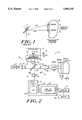
- FIG. 1shows an object 28 being scanned by an optical beam.
- a first beam 101is incident on a scanning mirror 71 which reflects beam 101 as beam 103 which is incident on object 28 at region A.
- Mirror 71rotates about pivot P in a controlled manner by some type of rotating driver (not shown) which causes mirror 71 to move to a new position represented by reference numeral 71'.
- beam 103scans across object 28 in the transverse direction to region B.
- object 28scatters the radiation back towards some detection unit (not shown) which detects that scattered radiation coherently using radiation from a reference arm (not shown).
- the detection unit for capturing a one or two dimensional image of object 28involves capturing a series of values corresponding to a series of intensity measurements.
- This series of intensity measurementsin turn correspond to a series of regions of object 28 transversely scanned by beam 103 across object 28.
- this approach to acquiring measurements across a transverse direction of an objectis essentially a serial image capturing process. Consequently, the rate of image capture by such a serial system may be limited by the rate at which individual measurements are acquired and hence at the rate beam 103 is scanned across object 28. This holds regardless of whether or not beam 103 is scanned using a mechanical scanner such as mirror 71 or some other non-mechanical scanning mechanism such as acousto-optic devices.
- a second scanning meanssuch as a second mirror is added to enable scanning in a second transverse direction, the rate of acquisition of resulting two dimensional images is even further reduced.
- the power of radiation incident on a unit areais fixed, e.g., optical measurements of the human eye.illuminating a human retina.
- simultaneous or parallel illumination and acquisition of informationrepresents a more efficient approach to performing optical measurements than any transverse scanning approach.
- An object of the inventionis to provide an apparatus and method of acquiring images of an object in a parallel manner without any transverse scanning across the object.
- Another object of the inventionis to provide an apparatus and method which can acquire one or two dimensional images at a high rate.
- Another object of the inventionis to provide an apparatus and method of acquiring a series of two dimensional images along a third direction.
- Another object of the inventionis to provide an apparatus and method for acquiring one or two dimensional transverse images of an object without having to scan a beam across the object.
- Another object of the inventionis to provide a relatively inexpensive apparatus and method which can acquire multi-dimensional images.
- One advantage of the inventionis that it detects a one or two dimensional slice or region of an object without scanning the target radiation over the object.
- Another advantage of the inventionis that it can output two dimensional images of the object at high rates.
- Another advantage of the inventionis that it can scan and output a series of two dimensional images of the object along a third direction of the object.
- Another advantage of the inventionis that it is not limited to capturing regions of the object in the form of a straight line or a flat plane but instead can capture curved lines or curved two dimensional regions of the object.
- One feature of the inventionis that it uses a source for outputting radiation having a short coherence length.
- Another feature of the inventionis that it employs heterodyne detection over two dimensions.
- Another feature of the inventionis that it uses a two dimensional array detector such as a charge coupled device.
- Another feature of the inventionis that it employs heterodyne detection over the two dimensions of the charge coupled device.
- the charge couple deviceoutputs signals corresponding to two dimensional slices of the object.
- an apparatus for acquiring an at least one dimensional image of a region of an object without any transverse scanningincluding: a source for outputting radiation having a short coherence length; means for splitting the radiation into reference radiation and object radiation; means for receiving the object radiation and directing the object radiation toward the region of the object; means for receiving the reference radiation and directing the reference radiation through a reference path; and array detecting means for receiving a portion of the object radiation scattered off of the region and a portion of the reference radiation, and for detecting incident intensity in a parallel fashion over the at least one dimension resulting from the portion of the reference radiation coherently interfering with the portion of the object radiation scattered from the region and for outputting a signal corresponding to the incident intensity, wherein the portion of the reference radiation requires a reference delay time to travel from the means for splitting to the array detecting means and the portion of the object radiation requires an object delay time to travel from the means for splitting to the region and then to the array detecting means.
- the array detecting meanscomprises a two dimensional array detecting means for receiving the portion of the object radiation and the portion of the reference radiation, for detecting the incident intensity over two dimensions resulting from the portion of the reference radiation coherently interfering with the portion of the object radiation scattered from the region and for outputting the signal corresponding to the incident intensity.
- an apparatus for acquiring a two dimensional image of a region of an objectcomprising: an optical source for outputting a first optical beam having a short coherence length; means for splitting the first optical beam into a reference beam and an object beam; means for receiving the object beam and directing the object beam toward the region of the object and for collecting a portion of the object beam scattered off of the region; means for receiving the reference beam and directing the reference beam through a reference path; and a two dimensional array detecting means for receiving a portion of the object beam and a portion of the reference beam, for detecting incident intensity over two dimensions resulting from the portion of the reference beam coherently interfering with the portion of the object beam scattered from the region and for outputting a signal corresponding to the incident intensity, wherein the portion of the reference beam requires a reference delay time to travel from the means for splitting to the two dimensional array detecting means and the portion of the object beam requires an object delay time to travel from the means for splitting to the region to the two dimensional array
- a method for acquiring a two dimensional image of a region of an objectcomprising the steps of: outputting radiation having a short coherence length; splitting the radiation using a splitter into reference radiation and object radiation; receiving, using an optical guide, the object radiation and directing the object radiation toward the region of the object and for collecting a portion of the object radiation scattered off of the region; receiving the reference radiation and directing the reference radiation through a reference path; receiving a portion of the object radiation and a portion of the reference radiation and detecting incident intensity over two dimensions using a two dimensional array detector resulting from the portion of the reference radiation coherently interfering with the portion of the object radiation scattered from the region; and outputting a signal corresponding to the incident intensity, wherein the portion of the reference radiation requires a reference delay time to travel from the splitter to the two dimensional array detector and the portion of object radiation requires an object delay time to travel from the splitter to the region and back to the two dimensional array detector.
- FIG. 1shows an object being transversely scanned by a beam according to previous methods.
- FIG. 2shows an imaging system according to one embodiment of the invention.
- FIG. 3is a simplified version of the optical paths within the system of FIG. 2.
- FIG. 4Ashows one example of an intermediate frequency signal resulting from coherently detecting an interference pattern produced by overlapping radiation scattered from the reference path and the object path and FIG. 4B shows this same output portion after demodulation.
- FIG. 5corresponds to FIG. 3 with spatially expanded radiation 17a, 17a', 17b, 17b', 18a, 18b' as shown in FIG. 2.
- FIGS. 6A, 6B and 6Cshow a front view of the reference scatterer, a region in the object, and the detecting surface of the detector array, respectively.
- FIG. 7shows an embodiment in which the reference unit of FIG. 2 has been replaced by an alternate reference unit and, in particular, the scatterer of FIG. 2 has been replaced with a curved scatterer.
- FIG. 8shows a more detailed schematic representation of image detection and processing unit.
- FIG. 2shows an imaging system 10 according to one embodiment of the invention.
- a source 12outputs radiation with a short coherence length CL outputs radiation 14 which is collimated by collimating lens 15 into collimated radiation 16 which travels toward a splitter 22.
- a short coherence length CLis a coherence length which is less than the desired longitudinal resolution ( ⁇ z' in FIG. 2).
- Collimated radiation 16can be made elliptical using an anamorphic beam expander or cylindrical lens (i.e., lens 15 can be an anamorphic beam expander or a cylindrical lens) or it can be made more circular (i.e., lens 15 can be a lens with approximately equal power in all transverse directions).
- reference radiation 17aA first portion of radiation 16 referred to here as reference radiation 17a is directed into a reference arm 30 by splitter 22 and a second portion of radiation 16 referred to here as image radiation 17b passes into an image arm 26.
- Reference radiation 17atravels to a reference unit 31 which includes a reference scatterer 32 and a scanning mechanism 39. A portion of reference radiation 17a is scattered back from reference scatterer 32 toward splitter 22 as radiation 17a'.
- Image radiation 17btravels to object or sample 28 through optics 81 which can be one or more lenses, a beam expander, a beam contractor or even possibly free space depending on the desired size of beam 17b incident on object 28. A portion of image radiation 17b is scattered back toward splitter 22 as radiation 17b'.
- a portion of radiation 17a' from reference arm 30passes through splitter 22 toward a charge coupled device (CCD) array detector 54 as radiation 18a'.
- CCD array detector 54can be made to match that of the collimated radiation.
- CCD array detector 54can be a one dimensional CCD array if radiation 16 is elliptical and a two dimensional detector array if radiation 16 is more cylindrical.
- a portion of radiation 17b' from image arm 26is redirected by splitter 22 toward detector 54 as radiation 18b'.
- the path length from splitter 22 to reference scatterer 32 back to splitter 22 and then through to detector 54will be referred to as the reference path length L R and the time for radiation 16 to travel the reference path length will be referred to as the reference delay time T R .
- the path length from splitter 22 to object 28 back to splitter 22 and then to detector 54is the object path L O and the time for radiation 16 to travel the object path length is the object delay time T O .
- optics 50which can be used to expand, compress or otherwise fill CCD detector 54.
- optics 50can include a beam compressor, beam expander or other optical elements known in the art.
- Optics 50then compresses or expands radiation 18a' and 18b' and outputs that radiation to an image detection and processing unit 52.
- Image detection and processing unit 52includes a charge coupled device (CCD) 54 which detects the intensity pattern from radiation 18a' and radiation 18b'.
- CCDcharge coupled device
- This intensity patternwill include coherent interference signals, i.e., homodyne or heterodyne detection can be achieved, provided the absolute value of the difference between path length L R and L O is approximately within the coherence length (CL) of source 12.
- Image detection and processing unitwill be described in more detail with reference to FIG. 8 below.
- a computer 57allows a user to control the process of image acquisition performed by image detection and processing unit 52 and displays of resulting images on monitor 59 or stores them on a hard disk (not shown) or some other digital storage device.
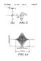
- FIG. 3is a simplified version of the optical paths within system 10 using a single ray of radiation 17a, 17a', 17b, 17b', 18a', 18b' of FIG. 2.
- the path length from splitter 22 to reference scatterer 32is defined as d1
- the path length from splitter 22 to a region 202 to be imagedis defined as d2
- the path length from splitter 22 to CCD detector 54is defined as d3.
- the reference path length L R discussed aboveis 2d1+d3
- the object path length L Ois 2d2+d3.
- the absolute value of the difference between L R and L O
- detector 54can detect and output this intermediate frequency signal. Moreover, when the velocity V is large enough, the resulting Doppler shift f D will be higher than the predominant low frequency (1 /f type) noise spectrum. For an 830 nm wavelength output from source 12, which might be a typical source wavelength, this occurs for a velocity V above approximately 1 mm/sec.
- path lengths L R and L Oare initially equal with the beam at a desired initial scan depth in object 28.
- the point in object 28 at which the path lengths are equalis scanned to successively greater depths within object 28.
- radiation scatteringoccurs and is a function of optical characteristics of object 28 such as refractive index variations, as well as absorption, scattering and spectral characteristics of object 28 through which radiation 17b' is passing.
- FIG. 4Ashows one example of an intermediate frequency signal output by detector 54 for a single scatterer at given depth point (see FIG. 3) in object 28, where the absolute value of the difference between the object path length L O and the reference path length L R is less than the coherence length (CL) of the light source (i.e.,
- the intermediate frequency signalappears for a time T which is the absolute value of the difference between the reference delay time T R and the object delay time T O , i.e.,
- the intermediate frequency signal shown in 4Aalso has an envelope signal superimposed thereon as discussed in the parent to this application.
- the coherence length CL of source 12determines available system resolution ( ⁇ z') in the z direction and the intermediate frequency output from detector 54 is indicative of scattering obtained at a particular depth z within object 28. Consequently, successive interferometric outputs obtained during a scan form profiles of the optical characteristics of object 28.
- the profilescan be index, scattering (even microstructure scattering), absorption or refractive index profiles within the samples where scattering is normally maximum and may have some lesser peaks in a predetermined pattern, depending on the scattering characteristics of the medium at the scan depth.
- FIG. 5is a simplified depiction of a parallel image capture system which corresponds to FIG. 3 with spatially expanded radiation 17a, 17a', 17b, 17b', 18a', 18b' as shown in FIG. 2.
- FIG. 5is referred to as simplified, because it depicts rays 1-4 with no crossing or overlapping which in practice occurs to some degree. Again, these rays can be in one or two transverse directions.
- coherent detectionfor a particular ray--say ray 1--only occurs when the absolute value of the optical path difference L R (xi,yj,zk)-L O (xi',yj',zk') for that ray is within the coherence length CL of source 12. Moreover, this must be true for each ray of radiation 18a' and 18b'.
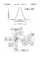
- FIGS. 6A, 6B and 6Cshow a front view of reference scatterer 32, a region 202 in object 28 and detector surface 302 of detector array 54, respectively.
- the front viewsare shown in two transverse directions, it being understood that when radiation 16 is elliptical, only one dimension need be shown.
- radiation in two transverse directionsis discussed, however, all aspects of image acquisition in one dimension is analogous to the below discussion of two directions.
- the following discussionrepresents a simplified discussion of the primary processes which take place in parallel image capture, it being understood that there will be crosstalk between rays in the reference or object paths.
- FIG. 6Ashows ray 1, ray 2, ray 3 and ray 4 which are incident on scatterer 32 at locations (x1,y1,z1), (x2,y1,z1), (x3,y1,z1) and (x4,y1,z1), respectively.
- the longitudinal position of scatterer 32is determined by the coordinate z and hence z1, z2 and z3 represent three different longitudinal positions of reference scatterer 32.
- the longitudinal position z of scatterer 32changes but the transverse coordinates (xi,yj) of rays 1-4 does not necessarily have to vary.
- FIG. 6Bshows rays 1, 2, 3 and 4 which are incident on region 202 of object 28 at locations (x1',y1',z1'), (x2',y1',z1'), (x3',y1',z1') and (x4',y1',z1'), respectively.
- the longitudinal position of region 202is determined by the coordinate z' and hence z1', z2' and z3' represent three different longitudinal positions of region 202.
- the longitudinal positions z' of region 202 being imagedchanges from z1', z2' and z3', as scatterer 32 changes from z1, z2, and z3, respectively.
- FIG. 6Cshows rays 1, 2, 3 and 4 which are incident on scatterer 32 on detection elements 302 at locations (x1",y1"), (x2",y1"), (x3",y1") and (x4",y1"), respectively.
- the number of subregions 302can range from a few to several thousand depending on the desired spatial resolution ⁇ x' and ⁇ y' of regions 1, 2, 3 in object 28.
- I(x",y")is the intensity of radiation incident on element 302 at location (x",y”).
- no intermediate frequency signalcan appear at the element 302 corresponding to that ray.
- path lengths L R (xi,yj,zk) and L O (xi',yj',zk') for all raysare initially equal at a desired initial scan depth z' in object 28.
- an entire plane (or line if radiation 16 is elliptical) in object 28 at which the path lengths are equalis scanned to successively greater depths within object 28.
- radiation scatteringoccurs and is a function of the refractive index variation for the material through which the radiation is passing and of such index boundaries at each subregion (xi',yj').
- the longitudinal scaninvolved scanning a plane (or line if only one transverse is being used) through object 28. This longitudinal scan is not, however, limited to a plane, but instead can be any two dimensional shape (or one dimensional curve) and it is the shape of scatterer 32 that determines the shape of regions longitudinally scanned through object 28 as will be discussed below.
- the heterodyne detection processwill now be discussed when subregions (x,y) all move at a single velocity V.
- the Doppler shift frequency f Dis superimposed on the envelope signal as shown for a small portion of an intensity output in FIG. 4A.
- the envelope signal shown in FIG. 4Awill be present at every detecting surface 302 (see FIG. 6C) which receives object scattered radiation 18b' from a corresponding subregion (x,y) on object 28.
- FIG. 4Bshows this same output portion after demodulation. Again, if the velocity V is large enough, the resulting Doppler shift frequency will be above the 1/f type noise spectrum of the system.
- Reference scatterer 32is secured to mechanism 39 (FIG. 2) which moves the scatterer 32 toward and away from splitter 22 in a particular pattern.
- mechanism 39moves scatterer 32 away from splitter 22 at a uniform, relatively high velocity V.
- the desired value of velocity Vdepends on the wavelength of radiation output by source 12. Regardless of the value of velocity V, it is desirable that all subregions (xi,yj) on scatterer 32 move at a single velocity V to ensure that each ray scattered by each subregion (xi',yj') is Doppler shifted by the same frequency f D . In that case, each pixel will have the same intermediate frequency signal (provided object radiation is received from object 28) indicative of the optical characteristics of subregion (xi',yj').
- each of the subregions (xi',yj') that does have such an intermediate frequency signalcan be demodulated in a manner analogous to that discussed above with respect to a single ray system.
- all subregions (xi,yj) of scatterer 32must move at a single velocity. This can be achieved in several ways.
- Mechanism 39may also return scatterer 32 to its initial position at substantially the same rate V, movements of the mirror thus being in a triangular pattern. With a triangular scan, readings or measurements can be taken with scatterer 32 moving in either one of the two directions, or can be taken with scatterer 32 moving in both directions.
- Mechanism 39may be any one of a Variety of devices adapted for performing the mirror translation function.
- mechanism 39could be a stepper motor, the motion of which is applied to scatterer 32 through an averaging mechanism to provide uniform velocity.
- a DC servo motormight also be utilized to obtain the desired motion.
- Various electromagnetic actuatorsfor example, a speaker coil, may also be utilized for moving scatterer 32. With such electromagnetic actuators, detection of scatterer position and servo-control thereof are also required in order to achieve the desired uniform motion. More specifically, in such a system, a signal indicative of desired scatterer position at each point in the scatterer travel path would be compared against a signal from a detector of actual scatterer position and any resulting error signals utilized to control the actuator to maintain scatterer 32 moving at the desired constant velocity. It would also be possible to use a servo-controlled galvanometer driven linear translator for mechanism 39.
- reference unit 31 and in particular mechanism 39 with scatterer 32can be modified to provide a series of two dimensional images in the transverse direction (or one transverse dimensional images if radiation 16 is elliptical) at a single depth point z.
- mechanism 39vibrates or dithers scatterer 32 back and fourth about a single point z1 at a frequency fm.
- the vibrating frequency f mshould be selected to be great enough to ensure that the resulting intermediate frequency signal is above the 1/f type noise floor of system 10 and sufficient to prevent aliasing.
- one or more acousto-optic modulatorscan be used to impose the desired optical frequency offset between the reference and object beam.
- an intermediate frequency signal output from a particular element 302will be present only if radiation 17b' is scattered from a particular subregion (x',y').
- a two dimensional imagecan be created by determining which elements 302 at (xi", yj") output an intermediate frequency signal and hence which subregions (xi',yj') scatter radiation 17b'.
- region z1'physically varies with time so that subregions (xi',yj') may scatter radiation 17b' back towards splitter 22 during one data acquisition time and not scatter radiation 17b' at a later data acquisition time, the resulting two dimensional image will itself change with time.
- system 10 used in this modeprovides a two dimensional real time monitoring system.
- an additional frequency shift of either radiation 17a, 17a' and/or radiation 18a, 18a'can be introduced by adding modulating units in either path 26 or path 30.
- modulating unitsin either path 26 or path 30.
- the resulting intermediate frequency signal output at each element 302will be a signal having a carrier frequency F S and frequency modulated by a signal proportional to cos(f m t). If F S is greater than the noise floor of system, scatterer 32 need not be scanned at high frequencies f m and still be well above the noise floor.
- FIG. 7shows an embodiment in which reference unit 31 of FIG. 2 has been replaced by reference unit 830 and, in particular, scatterer 32 has been replaced with a curved scatterer 832.
- curved scatterer 832is moved toward and away from splitter 22 as before. However, this motion translates into longitudinally scanning curved regions 1, 2, 3 through object 28. Any other shaped scatterer can be used as scatterer 32 and the shape of that scatter translates into correspondingly shaped regions in object. Consequently, this control over the shape of regions scanned in object 28 can be tailored to the specific application. For example, if 28 represents a human eye, it may be desirable to form scanning regions in the eye with approximately the same curvature as the cornea or lenses in the eye.
- reflector 832can be a deformable mirror such as a metal plated piece of rubber the exact shape being either mechanically or electrically controllable, the latter making it possible to modify the shape of the region longitudinally scanned in real time.
- FIG. 8shows a more detailed schematic representation of image detection and processing unit 52.
- image detection and processing unit 52includes CCD array 54 followed by front end electronics 801.
- CCD detector 54itself includes an imaging area 804, a frame store area 809 and CCD interface unit 815.
- Front end electronics 801includes analog-to-digital converters 821, logic unit 832', first-in-first-out (FIFO) unit 841 and digital signal processing unit 851.
- a system clock 861provides a synchronizing clock signal to synchronize CCD array 54 with front end electronics 801.
- CCD array 54can be used as CCD array 54 and preferably CCD 54 should have a fast frame rate, high quantum efficiency, frame transfer and multiple readouts.
- A/D converterscan also be standard, commercially available A/D converters, preferably having a several MHz conversion rates and at least 12 bit conversion.
- DSP 851can be from Texas Instrument's Model TMS 3200 family.
- Image detection and processing unit 52operates as follows.
- CCD array 54integrates an intensity pattern on imaging area 804 made of elements 803. Once the image is captured, it is mapped to frame store area 809 to be transferred out of CCD array 54 via interface unit 815.
- Frame store area 809is used in order that imaging area 804 can be freed up to capture a new image while frame store area 809 transmits the previous image via interface unit 815 to front end electronics 801.
- frame store area 809has multiple output lines 811 (four such lines are shown but more or fewer are possible) to interface unit 815 which includes buffer amplifiers, double correlated sampling and filtering electronics none of which are shown in FIG. 8 but are known in the art.
- the resulting signalsare then transmitted via lines 823 to analog-to-digital converter 821 which includes parallel analog-to-digital converters 821. Since the rate at which images are transmitted from CCD array 54 largely determines the rate at which images can be acquired, multiple lines 811 and 823 are used to transmit signals from frame store area 809 to front end electronics 801. Consequently, the more output lines frame store area 809 has, the higher the rate at which frames of signals are captured by CCD array 54.
- the signals output on lines 823are respectively analog-to-digitally converted into digital signals which in turn are output to logic unit 832' via respective digital lines 833.
- Logic unit 832'which rearranges the digital signals into a serial form outputs the data to FIFO 841 via line 843.
- the digital signals received by FIFO 841are then output via line 853 to digital signal processor (DSP) 851 in the order they were output from frame store area 809.
- DSPdigital signal processor
- Clock 861synchronizes the rate at which CCD 54 captures and outputs images as well as the rates
- A/D converters 821digitize the signals received from CCD 54 as well as the rate at which logic unit 832' filters and outputs data to FIFO 841. The data is then output in the order it was received to DSP 851 which processes the data as follows.
- detection unit 52performs digital signal processing on the received images in a manner analogous to that discussed in the parent applications to this application.
- frame capture timeis chosen so that there are more than two samples captured per intermediate frequency cycle, which as discussed above, can result from Doppler induced frequency shift, acousto-optic frequency shift, etc, . . . .
- aliasingcan be avoided.
- the scannersweeps the measurement window longitudinally through sample region 202. During this time, a series of samples are recorded for each pixel in FIG. 6C. Thus, a three dimensional data set is captured indicating the optical profiles of the object.
- DSP 851processes sequential samples from the same pixel by digitally band pass filtering around the center frequency followed by digitally rectifying and low pass filtering to remove double frequency terms.
- DSP 851performs a parallel envelope detection operation on the CCD output. Additional filtering can be used to extract and/or compare information (such as cross pixel scattering) from nearby pixels to further increase the utility of the measurements.
- the processingcan involve multiple measurements and averaging to further increase sensitivity. Since the processing is performed digitally, additional information such as phase information can be extracted and/or utilized to improve sensitivity (e.g., improving resolution of the system) as well as provide other useful information. All of the above processing can be done in real time or the digital samples can be stored and then processed later in computer 57.
Landscapes
- Health & Medical Sciences (AREA)
- Life Sciences & Earth Sciences (AREA)
- Physics & Mathematics (AREA)
- General Physics & Mathematics (AREA)
- General Health & Medical Sciences (AREA)
- Surgery (AREA)
- Veterinary Medicine (AREA)
- Engineering & Computer Science (AREA)
- Biomedical Technology (AREA)
- Heart & Thoracic Surgery (AREA)
- Medical Informatics (AREA)
- Molecular Biology (AREA)
- Public Health (AREA)
- Animal Behavior & Ethology (AREA)
- Biophysics (AREA)
- Radiology & Medical Imaging (AREA)
- Nuclear Medicine, Radiotherapy & Molecular Imaging (AREA)
- Pathology (AREA)
- Ophthalmology & Optometry (AREA)
- Spectroscopy & Molecular Physics (AREA)
- Optics & Photonics (AREA)
- Chemical & Material Sciences (AREA)
- Analytical Chemistry (AREA)
- Biochemistry (AREA)
- Immunology (AREA)
- Investigating Or Analysing Materials By Optical Means (AREA)
Abstract
Description
Claims (33)
Priority Applications (2)
| Application Number | Priority Date | Filing Date | Title |
|---|---|---|---|
| US08/253,059US5465147A (en) | 1991-04-29 | 1994-06-02 | Method and apparatus for acquiring images using a ccd detector array and no transverse scanner |
| PCT/US1995/006075WO1995033971A1 (en) | 1994-06-02 | 1995-05-16 | Method and apparatus for acquiring images |
Applications Claiming Priority (3)
| Application Number | Priority Date | Filing Date | Title |
|---|---|---|---|
| US69287791A | 1991-04-29 | 1991-04-29 | |
| US07/875,670US5321501A (en) | 1991-04-29 | 1992-04-29 | Method and apparatus for optical imaging with means for controlling the longitudinal range of the sample |
| US08/253,059US5465147A (en) | 1991-04-29 | 1994-06-02 | Method and apparatus for acquiring images using a ccd detector array and no transverse scanner |
Related Parent Applications (1)
| Application Number | Title | Priority Date | Filing Date |
|---|---|---|---|
| US07/875,670Continuation-In-PartUS5321501A (en) | 1991-04-29 | 1992-04-29 | Method and apparatus for optical imaging with means for controlling the longitudinal range of the sample |
Publications (1)
| Publication Number | Publication Date |
|---|---|
| US5465147Atrue US5465147A (en) | 1995-11-07 |
Family
ID=22958658
Family Applications (1)
| Application Number | Title | Priority Date | Filing Date |
|---|---|---|---|
| US08/253,059Expired - LifetimeUS5465147A (en) | 1991-04-29 | 1994-06-02 | Method and apparatus for acquiring images using a ccd detector array and no transverse scanner |
Country Status (2)
| Country | Link |
|---|---|
| US (1) | US5465147A (en) |
| WO (1) | WO1995033971A1 (en) |
Cited By (303)
| Publication number | Priority date | Publication date | Assignee | Title |
|---|---|---|---|---|
| WO1997026756A1 (en)* | 1996-01-17 | 1997-07-24 | Pixel Vision, Inc. | Optical detector for a narrow beam |
| WO1998002777A1 (en)* | 1996-07-13 | 1998-01-22 | The Secretary Of State For Defence In Her Britannic Majesty's Government Of The United Kingdom Of Great Britain And Northern Ireland | Laser device |
| US5847827A (en)* | 1995-06-23 | 1998-12-08 | Carl Zeiss Jena Gmbh | Coherence biometry and coherence tomography with dynamic coherent |
| US5921926A (en)* | 1997-07-28 | 1999-07-13 | University Of Central Florida | Three dimensional optical imaging colposcopy |
| US5943134A (en)* | 1996-06-17 | 1999-08-24 | The Institute Of Physical And Chemical Research | Method of measuring thickness and refractive indices of component layers of laminated structure and measuring apparatus for carrying out the same |
| US5943116A (en)* | 1997-04-01 | 1999-08-24 | Johns Hopkins University | System for imaging an ocular fundus semi-automatically at high resolution and wide field |
| WO1999065431A1 (en) | 1998-06-17 | 1999-12-23 | The Lions Eye Institute Of Western Australia Incorporated | Z axis tracker |
| US6088100A (en)* | 1997-07-14 | 2000-07-11 | Massachusetts Institute Of Technology | Three-dimensional light absorption spectroscopic imaging |
| US6111645A (en)* | 1991-04-29 | 2000-08-29 | Massachusetts Institute Of Technology | Grating based phase control optical delay line |
| US6151127A (en)* | 1998-05-28 | 2000-11-21 | The General Hospital Corporation | Confocal microscopy |
| US6172752B1 (en)* | 1996-08-04 | 2001-01-09 | Matsushita Electric Industrial Co., Ltd. | Method and apparatus for simultaneously interferometrically measuring optical characteristics in a noncontact manner |
| US6174291B1 (en) | 1998-03-09 | 2001-01-16 | Spectrascience, Inc. | Optical biopsy system and methods for tissue diagnosis |
| US6191862B1 (en) | 1999-01-20 | 2001-02-20 | Lightlab Imaging, Llc | Methods and apparatus for high speed longitudinal scanning in imaging systems |
| US6198540B1 (en)* | 1997-03-26 | 2001-03-06 | Kowa Company, Ltd. | Optical coherence tomography have plural reference beams of differing modulations |
| US6201608B1 (en) | 1998-03-13 | 2001-03-13 | Optical Biopsy Technologies, Inc. | Method and apparatus for measuring optical reflectivity and imaging through a scattering medium |
| US6385358B1 (en) | 1998-03-30 | 2002-05-07 | The Regents Of The University Of California | Birefringence insensitive optical coherence domain reflectometry system |
| US6388788B1 (en) | 1998-03-16 | 2002-05-14 | Praelux, Inc. | Method and apparatus for screening chemical compounds |
| AU750778B2 (en)* | 1998-06-17 | 2002-07-25 | Lions Eye Institute Limited | Z axis tracker |
| US6445939B1 (en) | 1999-08-09 | 2002-09-03 | Lightlab Imaging, Llc | Ultra-small optical probes, imaging optics, and methods for using same |
| WO2002077695A1 (en)* | 2001-03-21 | 2002-10-03 | The Regents Of The University Of Colorado | High-speed confocal microscope |
| US6485413B1 (en) | 1991-04-29 | 2002-11-26 | The General Hospital Corporation | Methods and apparatus for forward-directed optical scanning instruments |
| US20030036855A1 (en)* | 1998-03-16 | 2003-02-20 | Praelux Incorporated, A Corporation Of New Jersey | Method and apparatus for screening chemical compounds |
| US20030045798A1 (en)* | 2001-09-04 | 2003-03-06 | Richard Hular | Multisensor probe for tissue identification |
| US6546272B1 (en) | 1999-06-24 | 2003-04-08 | Mackinnon Nicholas B. | Apparatus for in vivo imaging of the respiratory tract and other internal organs |
| US6552796B2 (en) | 2001-04-06 | 2003-04-22 | Lightlab Imaging, Llc | Apparatus and method for selective data collection and signal to noise ratio enhancement using optical coherence tomography |
| WO2003058163A1 (en)* | 2001-12-05 | 2003-07-17 | Semiconductor Technologies & Instruments, Inc. | System and method for inspection using white light intererometry |
| US20030137670A1 (en)* | 2001-07-18 | 2003-07-24 | Barbato Louis J. | Electronics interface for an ultrasound console |
| US20030173502A1 (en)* | 1995-02-03 | 2003-09-18 | Dowski Edward Raymond | Wavefront coding interference contrast imaging systems |
| US20030184758A1 (en)* | 2000-09-04 | 2003-10-02 | Anders Bjarklev | Optical amplification in coherence reflectometry |
| US6655215B2 (en)* | 2001-06-15 | 2003-12-02 | Honeywell International Inc. | Inverse corner cube for non-intrusive three axis vibration measurement |
| US20030225455A1 (en)* | 2000-09-15 | 2003-12-04 | Cathey Wade Thomas | Extended depth of field optics for human vision |
| US20040004766A1 (en)* | 1995-02-03 | 2004-01-08 | Dowski Edward Raymond | Wavefront coded imaging systems |
| US20040080756A1 (en)* | 2000-10-19 | 2004-04-29 | Reid Phillip George | Surface profiler with vibration-damped horizontal reference surface |
| US20040102764A1 (en)* | 2000-11-13 | 2004-05-27 | Peter Balling | Laser ablation |
| US20040145808A1 (en)* | 1995-02-03 | 2004-07-29 | Cathey Wade Thomas | Extended depth of field optical systems |
| US20040263859A1 (en)* | 2003-06-24 | 2004-12-30 | Shoude Chang | Full-field optical coherence tomography and its application to multiple-layer information decoding |
| US6842297B2 (en) | 2001-08-31 | 2005-01-11 | Cdm Optics, Inc. | Wavefront coding optics |
| US6873733B2 (en) | 2001-01-19 | 2005-03-29 | The Regents Of The University Of Colorado | Combined wavefront coding and amplitude contrast imaging systems |
| US20050070772A1 (en)* | 2001-09-20 | 2005-03-31 | Visual Pathways, Inc. | Optical alignment apparatus |
| US20050113678A1 (en)* | 2002-01-15 | 2005-05-26 | Villard Joseph W. | Methods and compositions to reduce scattering of light during therapeutic and diagnostic imaging procedures |
| US6911638B2 (en) | 1995-02-03 | 2005-06-28 | The Regents Of The University Of Colorado, A Body Corporate | Wavefront coding zoom lens imaging systems |
| EP1582142A1 (en)* | 2004-03-30 | 2005-10-05 | Kabushiki Kaisha TOPCON | Optical interferometer for imaging at several depth regions of an object |
| US20050254061A1 (en)* | 2004-05-14 | 2005-11-17 | Alphonse Gerard A | Low coherence interferometry for detecting and characterizing plaques |
| US20050254060A1 (en)* | 2004-05-14 | 2005-11-17 | Alphonse Gerard A | Low coherence interferometry for detecting and characterizing plaques |
| US20050254059A1 (en)* | 2004-05-14 | 2005-11-17 | Alphonse Gerard A | Low coherence interferometric system for optical metrology |
| US6980299B1 (en) | 2001-10-16 | 2005-12-27 | General Hospital Corporation | Systems and methods for imaging a sample |
| US20060058682A1 (en)* | 2002-06-12 | 2006-03-16 | Miller Donald T | Method and apparatus for improving both lateral and axial resolution in ophthalmoscopy |
| US20060095065A1 (en)* | 2004-09-24 | 2006-05-04 | Tetsuaki Tanimura | Fluid occluding devices and methods |
| WO2006045168A1 (en)* | 2004-10-26 | 2006-05-04 | Photonita Ltda | Incoherent light interferometer for the measurement of internal and external cylindrical and nearly cylindrical surfaces |
| US20060103850A1 (en)* | 2004-11-12 | 2006-05-18 | Alphonse Gerard A | Single trace multi-channel low coherence interferometric sensor |
| US20060119858A1 (en)* | 2004-12-02 | 2006-06-08 | Knighton Robert W | Enhanced optical coherence tomography for anatomical mapping |
| US20060132790A1 (en)* | 2003-02-20 | 2006-06-22 | Applied Science Innovations, Inc. | Optical coherence tomography with 3d coherence scanning |
| US7116429B1 (en)* | 2003-01-18 | 2006-10-03 | Walecki Wojciech J | Determining thickness of slabs of materials by inventors |
| US20060241503A1 (en)* | 2005-02-10 | 2006-10-26 | Lightlab Imaging, Inc. | Optical coherence tomography apparatus and methods |
| US7184148B2 (en) | 2004-05-14 | 2007-02-27 | Medeikon Corporation | Low coherence interferometry utilizing phase |
| US7231243B2 (en) | 2000-10-30 | 2007-06-12 | The General Hospital Corporation | Optical methods for tissue analysis |
| US20070188704A1 (en)* | 2006-02-16 | 2007-08-16 | Yasufumi Fukuma | Fundus Observation Device |
| US20070260198A1 (en)* | 2003-04-25 | 2007-11-08 | Lightlab Imaging, Llc | Flush catheter with flow directing sheath |
| US7294334B1 (en) | 2003-04-15 | 2007-11-13 | Advanced Cardiovascular Systems, Inc. | Methods and compositions to treat myocardial conditions |
| US20070263227A1 (en)* | 2006-05-12 | 2007-11-15 | The General Hospital Corporation | Processes, arrangements and systems for providing a fiber layer thickness map based on optical coherence tomography images |
| US7310150B2 (en) | 2002-01-11 | 2007-12-18 | The General Hospital Corporation | Apparatus and method for low coherence ranging |
| EP1831638A4 (en)* | 2004-11-12 | 2008-01-23 | Medeikon Corp | Single trace multi-channel low coherence interferometric sensor |
| US7327463B2 (en) | 2004-05-14 | 2008-02-05 | Medrikon Corporation | Low coherence interferometry utilizing magnitude |
| US7355716B2 (en) | 2002-01-24 | 2008-04-08 | The General Hospital Corporation | Apparatus and method for ranging and noise reduction of low coherence interferometry LCI and optical coherence tomography OCT signals by parallel detection of spectral bands |
| CN100380160C (en)* | 1998-03-16 | 2008-04-09 | 通用电气医疗集团生物科学公司 | Confocal microscopy imaging system |
| US7358516B2 (en) | 2001-04-13 | 2008-04-15 | Carl Zeiss Ag | System and method for determining a position or/and orientation of two objects relative to each other as well as beam guiding arrangement, interferometer arrangement and device for changing an optical path length for use in such a system and method |
| US7361368B2 (en) | 2002-06-28 | 2008-04-22 | Advanced Cardiovascular Systems, Inc. | Device and method for combining a treatment agent and a gel |
| US7365859B2 (en) | 2004-09-10 | 2008-04-29 | The General Hospital Corporation | System and method for optical coherence imaging |
| US7366376B2 (en) | 2004-09-29 | 2008-04-29 | The General Hospital Corporation | System and method for optical coherence imaging |
| US7382949B2 (en) | 2004-11-02 | 2008-06-03 | The General Hospital Corporation | Fiber-optic rotational device, optical system and method for imaging a sample |
| US20080161696A1 (en)* | 2006-11-08 | 2008-07-03 | Lightlab Imaging, Inc. | Opto-acoustic imaging devices and methods |
| US20080165366A1 (en)* | 2007-01-10 | 2008-07-10 | Lightlab Imaging, Inc. | Methods and apparatus for swept-source optical coherence tomography |
| US7418169B2 (en) | 2006-02-01 | 2008-08-26 | The General Hospital Corporation | Apparatus for controlling at least one of at least two sections of at least one fiber |
| CN100419869C (en)* | 2005-10-25 | 2008-09-17 | 富士通株式会社 | recording and reproducing device |
| US7447408B2 (en) | 2004-07-02 | 2008-11-04 | The General Hospital Corproation | Imaging system and related techniques |
| US7474408B2 (en) | 2004-05-14 | 2009-01-06 | Medeikon Corporation | Low coherence interferometry utilizing phase |
| US7488930B2 (en) | 2006-06-02 | 2009-02-10 | Medeikon Corporation | Multi-channel low coherence interferometer |
| US20090081293A1 (en)* | 2007-09-20 | 2009-03-26 | Katsuyuki Murase | Sustained release of apo a-i mimetic peptides and methods of treatment |
| US20090081298A1 (en)* | 2007-09-20 | 2009-03-26 | Katsuyuki Murase | Sustained release of apo a-i mimetic peptides and methods of treatment |
| US20090081299A1 (en)* | 2007-09-20 | 2009-03-26 | Hossainy Syed F A | Sustained release of apo a-i mimetic peptides and methods of treatment |
| US7519096B2 (en) | 2003-06-06 | 2009-04-14 | The General Hospital Corporation | Process and apparatus for a wavelength tuning source |
| EP1011421A4 (en)* | 1997-02-24 | 2009-04-15 | Lucid Inc | System for facilitating pathological examination of a lesion in tissue |
| US20090122320A1 (en)* | 2007-11-12 | 2009-05-14 | Lightlab Imaging, Inc. | Imaging catheter with integrated reference reflector |
| US7538859B2 (en) | 2006-02-01 | 2009-05-26 | The General Hospital Corporation | Methods and systems for monitoring and obtaining information of at least one portion of a sample using conformal laser therapy procedures, and providing electromagnetic radiation thereto |
| US7551293B2 (en) | 2003-11-28 | 2009-06-23 | The General Hospital Corporation | Method and apparatus for three-dimensional spectrally encoded imaging |
| US7567349B2 (en) | 2003-03-31 | 2009-07-28 | The General Hospital Corporation | Speckle reduction in optical coherence tomography by path length encoded angular compounding |
| US20090270888A1 (en)* | 2008-04-23 | 2009-10-29 | Patel Himanshu N | Catheter System and Method for Boring through Blocked Vascular Passages |
| US20090306520A1 (en)* | 2008-06-02 | 2009-12-10 | Lightlab Imaging, Inc. | Quantitative methods for obtaining tissue characteristics from optical coherence tomography images |
| WO2009155416A1 (en)* | 2008-06-18 | 2009-12-23 | Eyelab Group, Llc | System and method for determining volume-related parameters of ocular and other biological tissues |
| US7643153B2 (en) | 2003-01-24 | 2010-01-05 | The General Hospital Corporation | Apparatus and method for ranging and noise reduction of low coherence interferometry LCI and optical coherence tomography OCT signals by parallel detection of spectral bands |
| US20100027029A1 (en)* | 2007-02-21 | 2010-02-04 | Agfa Healthcare Nv | System and Method for Optical Coherence Tomography and Method for Calibrating Said Type of System |
| US20100027020A1 (en)* | 2007-02-21 | 2010-02-04 | Agfa Healthcare Nv | System and Method for Optical Coherence Tomography |
| US20100027024A1 (en)* | 2007-02-21 | 2010-02-04 | Agfa Healthcare Nv | System and Method for Optical Coherence Tomography |
| US20100033726A1 (en)* | 2007-02-21 | 2010-02-11 | Agfa Healthcare Nv | System and Method for Optical Coherence Tomography |
| US20100067022A1 (en)* | 2007-02-21 | 2010-03-18 | Agfa Healthcare Nv | System for Optical Coherence Tomography |
| US20100091295A1 (en)* | 2007-02-21 | 2010-04-15 | Agfa Healthcare Nv | System and Method for Optical Coherence Tomography |
| US20100094127A1 (en)* | 2008-10-14 | 2010-04-15 | Lightlab Imaging, Inc. | Methods for stent strut detection and related measurement and display using optical coherence tomography |
| US7733497B2 (en) | 2003-10-27 | 2010-06-08 | The General Hospital Corporation | Method and apparatus for performing optical imaging using frequency-domain interferometry |
| US7732190B2 (en) | 2006-07-31 | 2010-06-08 | Advanced Cardiovascular Systems, Inc. | Modified two-component gelation systems, methods of use and methods of manufacture |
| US20100149543A1 (en)* | 2008-12-16 | 2010-06-17 | Agfa Healthcare N.V. | Method and System for Optical Coherence Tomography |
| US7742173B2 (en) | 2006-04-05 | 2010-06-22 | The General Hospital Corporation | Methods, arrangements and systems for polarization-sensitive optical frequency domain imaging of a sample |
| WO2010074321A1 (en)* | 2008-12-26 | 2010-07-01 | Canon Kabushiki Kaisha | Optical tomographic imaging apparatus |
| US7761139B2 (en) | 2003-01-24 | 2010-07-20 | The General Hospital Corporation | System and method for identifying tissue using low-coherence interferometry |
| US20100228124A1 (en)* | 2009-03-08 | 2010-09-09 | Jeffrey Brennan | Medical and veterinary imaging and diagnostic procedures utilizing optical probe systems |
| US7796270B2 (en) | 2006-01-10 | 2010-09-14 | The General Hospital Corporation | Systems and methods for generating data based on one or more spectrally-encoded endoscopy techniques |
| US20100253949A1 (en)* | 2007-11-12 | 2010-10-07 | Lightlab Imaging, Inc. | Miniature Optical Elements for Fiber-Optic Beam Shaping |
| US7843572B2 (en) | 2005-09-29 | 2010-11-30 | The General Hospital Corporation | Method and apparatus for optical imaging via spectral encoding |
| US7854944B2 (en) | 2004-12-17 | 2010-12-21 | Advanced Cardiovascular Systems, Inc. | Tissue regeneration |
| US7859679B2 (en) | 2005-05-31 | 2010-12-28 | The General Hospital Corporation | System, method and arrangement which can use spectral encoding heterodyne interferometry techniques for imaging |
| US7865231B2 (en) | 2001-05-01 | 2011-01-04 | The General Hospital Corporation | Method and apparatus for determination of atherosclerotic plaque type by measurement of tissue optical properties |
| US20110007321A1 (en)* | 2006-06-20 | 2011-01-13 | Carl Zeiss Meditec, Inc. | Spectral domain optical coherence tomography system |
| US7889348B2 (en) | 2005-10-14 | 2011-02-15 | The General Hospital Corporation | Arrangements and methods for facilitating photoluminescence imaging |
| US20110051143A1 (en)* | 2009-09-03 | 2011-03-03 | Axsun Technologies, Inc. | ASE Swept Source with Self-Tracking Filter for OCT Medical Imaging |
| US20110051148A1 (en)* | 2009-09-03 | 2011-03-03 | Axsun Technologies, Inc. | Filtered ASE Swept Source for OCT Medical Imaging |
| US7911621B2 (en) | 2007-01-19 | 2011-03-22 | The General Hospital Corporation | Apparatus and method for controlling ranging depth in optical frequency domain imaging |
| US20110071404A1 (en)* | 2009-09-23 | 2011-03-24 | Lightlab Imaging, Inc. | Lumen Morphology and Vascular Resistance Measurements Data Collection Systems, Apparatus and Methods |
| US20110071405A1 (en)* | 2009-09-23 | 2011-03-24 | Lightlab Imaging, Inc. | Apparatus, Systems, and Methods of in-vivo Blood Clearing in a Lumen |
| US7920271B2 (en) | 2006-08-25 | 2011-04-05 | The General Hospital Corporation | Apparatus and methods for enhancing optical coherence tomography imaging using volumetric filtering techniques |
| US7933021B2 (en) | 2007-10-30 | 2011-04-26 | The General Hospital Corporation | System and method for cladding mode detection |
| US7949019B2 (en) | 2007-01-19 | 2011-05-24 | The General Hospital | Wavelength tuning source based on a rotatable reflector |
| US20110151980A1 (en)* | 2009-12-22 | 2011-06-23 | Lightlab Imaging, Inc. | Torque limiter for an oct catheter |
| US7982879B2 (en) | 2006-02-24 | 2011-07-19 | The General Hospital Corporation | Methods and systems for performing angle-resolved fourier-domain optical coherence tomography |
| US20110178413A1 (en)* | 2010-01-19 | 2011-07-21 | Schmitt Joseph M | Intravascular optical coherence tomography system with pressure monitoring interface and accessories |
| US7985727B1 (en) | 2007-09-20 | 2011-07-26 | Abbott Cardiovascular Systems Inc. | Apo A-I mimetic peptides and methods of treatment |
| US7985728B1 (en) | 2007-09-20 | 2011-07-26 | Abbott Cardiovascular Systems Inc. | Sustained release of Apo A-I mimetic peptides and methods of treatment |
| US7995210B2 (en) | 2004-11-24 | 2011-08-09 | The General Hospital Corporation | Devices and arrangements for performing coherence range imaging using a common path interferometer |
| US8018598B2 (en) | 2004-05-29 | 2011-09-13 | The General Hospital Corporation | Process, system and software arrangement for a chromatic dispersion compensation using reflective layers in optical coherence tomography (OCT) imaging |
| US20110228280A1 (en)* | 2010-03-17 | 2011-09-22 | Lightlab Imaging, Inc. | Intensity Noise Reduction Methods and Apparatus for Interferometric Sensing and Imaging Systems |
| WO2011121999A1 (en)* | 2010-03-31 | 2011-10-06 | Canon Kabushiki Kaisha | Imaging apparatus and imaging method |
| US8040608B2 (en) | 2007-08-31 | 2011-10-18 | The General Hospital Corporation | System and method for self-interference fluorescence microscopy, and computer-accessible medium associated therewith |
| US8038991B1 (en) | 2003-04-15 | 2011-10-18 | Abbott Cardiovascular Systems Inc. | High-viscosity hyaluronic acid compositions to treat myocardial conditions |
| US8045177B2 (en) | 2007-04-17 | 2011-10-25 | The General Hospital Corporation | Apparatus and methods for measuring vibrations using spectrally-encoded endoscopy |
| US8081316B2 (en) | 2004-08-06 | 2011-12-20 | The General Hospital Corporation | Process, system and software arrangement for determining at least one location in a sample using an optical coherence tomography |
| US8083726B1 (en) | 2005-09-30 | 2011-12-27 | Advanced Cardiovascular Systems, Inc. | Encapsulating cells and lumen |
| US8097864B2 (en) | 2009-01-26 | 2012-01-17 | The General Hospital Corporation | System, method and computer-accessible medium for providing wide-field superresolution microscopy |
| US8115919B2 (en) | 2007-05-04 | 2012-02-14 | The General Hospital Corporation | Methods, arrangements and systems for obtaining information associated with a sample using optical microscopy |
| RU2446612C1 (en)* | 2011-03-29 | 2012-03-27 | Вячеслав Михайлович Смелков | Device for interferogram image signal generation |
| US8145018B2 (en) | 2006-01-19 | 2012-03-27 | The General Hospital Corporation | Apparatus for obtaining information for a structure using spectrally-encoded endoscopy techniques and methods for producing one or more optical arrangements |
| RU2448431C1 (en)* | 2011-03-15 | 2012-04-20 | Вячеслав Михайлович Смелков | Method of forming interference pattern signal and apparatus for realising said method |
| US8175685B2 (en) | 2006-05-10 | 2012-05-08 | The General Hospital Corporation | Process, arrangements and systems for providing frequency domain imaging of a sample |
| US8187621B2 (en) | 2005-04-19 | 2012-05-29 | Advanced Cardiovascular Systems, Inc. | Methods and compositions for treating post-myocardial infarction damage |
| US8192760B2 (en) | 2006-12-04 | 2012-06-05 | Abbott Cardiovascular Systems Inc. | Methods and compositions for treating tissue using silk proteins |
| US8208995B2 (en) | 2004-08-24 | 2012-06-26 | The General Hospital Corporation | Method and apparatus for imaging of vessel segments |
| US8303972B2 (en) | 2005-04-19 | 2012-11-06 | Advanced Cardiovascular Systems, Inc. | Hydrogel bioscaffoldings and biomedical device coatings |
| US8351665B2 (en) | 2005-04-28 | 2013-01-08 | The General Hospital Corporation | Systems, processes and software arrangements for evaluating information associated with an anatomical structure by an optical coherence ranging technique |
| US8358461B2 (en) | 2008-09-03 | 2013-01-22 | Lightlab Imaging Inc. | Wavelength-tunable light source |
| US8521259B2 (en) | 2001-06-20 | 2013-08-27 | Advanced Cardiovascular Systems, Inc. | Agents that stimulate therapeutic angiogenesis and techniques and devices that enable their delivery |
| CN103299231A (en)* | 2011-01-20 | 2013-09-11 | 应用精密公司 | Light-scanning systems |
| US8548571B2 (en) | 2009-12-08 | 2013-10-01 | Avinger, Inc. | Devices and methods for predicting and preventing restenosis |
| US8582109B1 (en) | 2011-08-01 | 2013-11-12 | Lightlab Imaging, Inc. | Swept mode-hopping laser system, methods, and devices for frequency-domain optical coherence tomography |
| US8582619B2 (en) | 2011-03-15 | 2013-11-12 | Lightlab Imaging, Inc. | Methods, systems, and devices for timing control in electromagnetic radiation sources |
| USRE44605E1 (en) | 2003-10-17 | 2013-11-19 | Axsun Technologies, Inc. | Integrated spectroscopy system |
| US8593619B2 (en) | 2008-05-07 | 2013-11-26 | The General Hospital Corporation | System, method and computer-accessible medium for tracking vessel motion during three-dimensional coronary artery microscopy |
| US8608661B1 (en) | 2001-11-30 | 2013-12-17 | Advanced Cardiovascular Systems, Inc. | Method for intravascular delivery of a treatment agent beyond a blood vessel wall |
| US8644913B2 (en) | 2011-03-28 | 2014-02-04 | Avinger, Inc. | Occlusion-crossing devices, imaging, and atherectomy devices |
| US8687201B2 (en) | 2012-08-31 | 2014-04-01 | Lightlab Imaging, Inc. | Optical coherence tomography control systems and methods |
| US8696695B2 (en) | 2009-04-28 | 2014-04-15 | Avinger, Inc. | Guidewire positioning catheter |
| US8711364B2 (en) | 2010-05-13 | 2014-04-29 | Oprobe, Llc | Optical coherence tomography with multiple sample arms |
| US8721077B2 (en) | 2011-04-29 | 2014-05-13 | The General Hospital Corporation | Systems, methods and computer-readable medium for determining depth-resolved physical and/or optical properties of scattering media by analyzing measured data over a range of depths |
| US8741326B2 (en) | 2006-11-17 | 2014-06-03 | Abbott Cardiovascular Systems Inc. | Modified two-component gelation systems, methods of use and methods of manufacture |
| US8747385B2 (en) | 2003-04-15 | 2014-06-10 | Abbott Cardiovascular Systems Inc. | Methods and compositions to treat myocardial conditions |
| US8764189B2 (en) | 2006-03-16 | 2014-07-01 | Carl Zeiss Meditec, Inc. | Methods for mapping tissue with optical coherence tomography data |
| US8804126B2 (en) | 2010-03-05 | 2014-08-12 | The General Hospital Corporation | Systems, methods and computer-accessible medium which provide microscopic images of at least one anatomical structure at a particular resolution |
| US8828433B2 (en) | 2005-04-19 | 2014-09-09 | Advanced Cardiovascular Systems, Inc. | Hydrogel bioscaffoldings and biomedical device coatings |
| US8831321B1 (en) | 2011-11-07 | 2014-09-09 | Lightlab Imaging, Inc. | Side branch detection methods, systems and devices |
| US8838213B2 (en) | 2006-10-19 | 2014-09-16 | The General Hospital Corporation | Apparatus and method for obtaining and providing imaging information associated with at least one portion of a sample, and effecting such portion(s) |
| US8854627B2 (en)* | 2001-07-16 | 2014-10-07 | Boston Scientific Scimed, Inc. | Electronically scanned optical coherence tomography with frequency modulated signals |
| US8861910B2 (en) | 2008-06-20 | 2014-10-14 | The General Hospital Corporation | Fused fiber optic coupler arrangement and method for use thereof |
| US8913793B2 (en) | 2005-09-09 | 2014-12-16 | Carl Zeiss Meditec, Inc. | Method of bioimage data processing for revealing more meaningful anatomic features of diseased tissues |
| US8922781B2 (en) | 2004-11-29 | 2014-12-30 | The General Hospital Corporation | Arrangements, devices, endoscopes, catheters and methods for performing optical imaging by simultaneously illuminating and detecting multiple points on a sample |
| US8926590B2 (en) | 2009-12-22 | 2015-01-06 | Lightlab Imaging, Inc. | Torque limiter for an OCT catheter |
| US8937724B2 (en) | 2008-12-10 | 2015-01-20 | The General Hospital Corporation | Systems and methods for extending imaging depth range of optical coherence tomography through optical sub-sampling |
| GB2516281A (en)* | 2013-07-17 | 2015-01-21 | Cambridge Consultants | Optical apparatus and methods |
| US8953911B1 (en) | 2011-10-28 | 2015-02-10 | Lightlab Imaging, Inc. | Spectroscopic imaging probes, devices, and methods |
| US8965487B2 (en) | 2004-08-24 | 2015-02-24 | The General Hospital Corporation | Process, system and software arrangement for measuring a mechanical strain and elastic properties of a sample |
| US9005672B2 (en) | 2006-11-17 | 2015-04-14 | Abbott Cardiovascular Systems Inc. | Methods of modifying myocardial infarction expansion |
| US9042963B2 (en) | 2012-01-09 | 2015-05-26 | Given Imaging Ltd. | System and method for acquiring images from within a tissue |
| US9060689B2 (en) | 2005-06-01 | 2015-06-23 | The General Hospital Corporation | Apparatus, method and system for performing phase-resolved optical frequency domain imaging |
| US9069130B2 (en) | 2010-05-03 | 2015-06-30 | The General Hospital Corporation | Apparatus, method and system for generating optical radiation from biological gain media |
| US9069396B2 (en) | 2013-03-12 | 2015-06-30 | Lightlab Imaging, Inc. | Controller and user interface device, systems, and methods |
| US9087368B2 (en) | 2006-01-19 | 2015-07-21 | The General Hospital Corporation | Methods and systems for optical imaging or epithelial luminal organs by beam scanning thereof |
| US9125562B2 (en) | 2009-07-01 | 2015-09-08 | Avinger, Inc. | Catheter-based off-axis optical coherence tomography imaging system |
| US9164240B2 (en) | 2011-03-31 | 2015-10-20 | Lightlab Imaging, Inc. | Optical buffering methods, apparatus, and systems for increasing the repetition rate of tunable light sources |
| US9178330B2 (en) | 2009-02-04 | 2015-11-03 | The General Hospital Corporation | Apparatus and method for utilization of a high-speed optical wavelength tuning source |
| US9173591B2 (en) | 2013-03-08 | 2015-11-03 | Lightlab Imaging, Inc. | Stent visualization and malapposition detection systems, devices, and methods |
| US9176319B2 (en) | 2007-03-23 | 2015-11-03 | The General Hospital Corporation | Methods, arrangements and apparatus for utilizing a wavelength-swept laser using angular scanning and dispersion procedures |
| US9242005B1 (en) | 2006-08-21 | 2016-01-26 | Abbott Cardiovascular Systems Inc. | Pro-healing agent formulation compositions, methods and treatments |
| US9254089B2 (en) | 2008-07-14 | 2016-02-09 | The General Hospital Corporation | Apparatus and methods for facilitating at least partial overlap of dispersed ration on at least one sample |
| US9295391B1 (en) | 2000-11-10 | 2016-03-29 | The General Hospital Corporation | Spectrally encoded miniature endoscopic imaging probe |
| US9330092B2 (en) | 2011-07-19 | 2016-05-03 | The General Hospital Corporation | Systems, methods, apparatus and computer-accessible-medium for providing polarization-mode dispersion compensation in optical coherence tomography |
| US9332942B2 (en) | 2008-01-28 | 2016-05-10 | The General Hospital Corporation | Systems, processes and computer-accessible medium for providing hybrid flourescence and optical coherence tomography imaging |
| US9341783B2 (en) | 2011-10-18 | 2016-05-17 | The General Hospital Corporation | Apparatus and methods for producing and/or providing recirculating optical delay(s) |
| US9345510B2 (en) | 2010-07-01 | 2016-05-24 | Avinger, Inc. | Atherectomy catheters with longitudinally displaceable drive shafts |
| US9345406B2 (en) | 2011-11-11 | 2016-05-24 | Avinger, Inc. | Occlusion-crossing devices, atherectomy devices, and imaging |
| US9345398B2 (en) | 2012-05-14 | 2016-05-24 | Avinger, Inc. | Atherectomy catheter drive assemblies |
| US9351642B2 (en) | 2009-03-12 | 2016-05-31 | The General Hospital Corporation | Non-contact optical system, computer-accessible medium and method for measurement at least one mechanical property of tissue using coherent speckle technique(s) |
| US9351698B2 (en) | 2013-03-12 | 2016-05-31 | Lightlab Imaging, Inc. | Vascular data processing and image registration systems, methods, and apparatuses |
| US9375158B2 (en) | 2007-07-31 | 2016-06-28 | The General Hospital Corporation | Systems and methods for providing beam scan patterns for high speed doppler optical frequency domain imaging |
| US9415550B2 (en) | 2012-08-22 | 2016-08-16 | The General Hospital Corporation | System, method, and computer-accessible medium for fabrication miniature endoscope using soft lithography |
| US9441948B2 (en) | 2005-08-09 | 2016-09-13 | The General Hospital Corporation | Apparatus, methods and storage medium for performing polarization-based quadrature demodulation in optical coherence tomography |
| US20160267630A1 (en)* | 2013-11-26 | 2016-09-15 | Fujifilm Corporation | Radiographic image processing device, method, and recording medium |
| US9464883B2 (en) | 2013-06-23 | 2016-10-11 | Eric Swanson | Integrated optical coherence tomography systems and methods |
| US9498247B2 (en) | 2014-02-06 | 2016-11-22 | Avinger, Inc. | Atherectomy catheters and occlusion crossing devices |
| US9498600B2 (en) | 2009-07-01 | 2016-11-22 | Avinger, Inc. | Atherectomy catheter with laterally-displaceable tip |
| US9510758B2 (en) | 2010-10-27 | 2016-12-06 | The General Hospital Corporation | Apparatus, systems and methods for measuring blood pressure within at least one vessel |
| US9539410B2 (en) | 2005-04-19 | 2017-01-10 | Abbott Cardiovascular Systems Inc. | Methods and compositions for treating post-cardial infarction damage |
| US9557154B2 (en) | 2010-05-25 | 2017-01-31 | The General Hospital Corporation | Systems, devices, methods, apparatus and computer-accessible media for providing optical imaging of structures and compositions |
| US9557156B2 (en) | 2012-05-14 | 2017-01-31 | Avinger, Inc. | Optical coherence tomography with graded index fiber for biological imaging |
| US20170038308A1 (en)* | 2014-02-26 | 2017-02-09 | Krones Ag | Apparatus and method for inspecting containers |
| US9592075B2 (en) | 2014-02-06 | 2017-03-14 | Avinger, Inc. | Atherectomy catheters devices having multi-channel bushings |
| CN106546178A (en)* | 2016-10-27 | 2017-03-29 | 华中科技大学 | The multi-layer transparent dielectric thickness measuring apparatus and method of confocal white light polarization interference |
| US9610064B2 (en) | 2011-05-31 | 2017-04-04 | Desmond Adler | Multimodal imaging system, apparatus, and methods |
| US9629528B2 (en) | 2012-03-30 | 2017-04-25 | The General Hospital Corporation | Imaging system, method and distal attachment for multidirectional field of view endoscopy |
| US20170139194A1 (en)* | 2015-11-17 | 2017-05-18 | Mitutoyo Corporation | Interference objective lens and reference surface unit set |
| US9668652B2 (en) | 2013-07-26 | 2017-06-06 | The General Hospital Corporation | System, apparatus and method for utilizing optical dispersion for fourier-domain optical coherence tomography |
| US9683928B2 (en) | 2013-06-23 | 2017-06-20 | Eric Swanson | Integrated optical system and components utilizing tunable optical sources and coherent detection and phased array for imaging, ranging, sensing, communications and other applications |
| US9687630B2 (en) | 2005-04-19 | 2017-06-27 | Abbott Cardiovascular Systems Inc. | Methods and compositions for treating post-cardial infarction damage |
| US9702762B2 (en) | 2013-03-15 | 2017-07-11 | Lightlab Imaging, Inc. | Calibration and image processing devices, methods, and systems |
| WO2017136857A1 (en)* | 2016-02-05 | 2017-08-10 | Mcbain Theodore Dean | System, method and device for confirmation of an operator's health condition and alive status |
| US9733460B2 (en) | 2014-01-08 | 2017-08-15 | The General Hospital Corporation | Method and apparatus for microscopic imaging |
| US9777053B2 (en) | 2006-02-08 | 2017-10-03 | The General Hospital Corporation | Methods, arrangements and systems for obtaining information associated with an anatomical sample using optical microscopy |
| US9784681B2 (en) | 2013-05-13 | 2017-10-10 | The General Hospital Corporation | System and method for efficient detection of the phase and amplitude of a periodic modulation associated with self-interfering fluorescence |
| US9788790B2 (en) | 2009-05-28 | 2017-10-17 | Avinger, Inc. | Optical coherence tomography for biological imaging |
| US9795301B2 (en) | 2010-05-25 | 2017-10-24 | The General Hospital Corporation | Apparatus, systems, methods and computer-accessible medium for spectral analysis of optical coherence tomography images |
| US20170343791A1 (en)* | 2016-05-30 | 2017-11-30 | Eric Swanson | Few-mode fiber endoscope |
| US9833221B2 (en) | 2013-03-15 | 2017-12-05 | Lightlab Imaging, Inc. | Apparatus and method of image registration |
| US9854979B2 (en) | 2013-03-15 | 2018-01-02 | Avinger, Inc. | Chronic total occlusion crossing devices with imaging |
| US9897538B2 (en) | 2001-04-30 | 2018-02-20 | The General Hospital Corporation | Method and apparatus for improving image clarity and sensitivity in optical coherence tomography using dynamic feedback to control focal properties and coherence gating |
| US9940723B2 (en) | 2014-12-12 | 2018-04-10 | Lightlab Imaging, Inc. | Systems and methods to detect and display endovascular features |
| US9949754B2 (en) | 2011-03-28 | 2018-04-24 | Avinger, Inc. | Occlusion-crossing devices |
| US9955863B2 (en) | 2015-05-28 | 2018-05-01 | Cylite Pty Ltd | High resolution 3-D spectral domain optical imaging apparatus and method |
| US9996921B2 (en) | 2015-05-17 | 2018-06-12 | LIGHTLAB IMAGING, lNC. | Detection of metal stent struts |
| US10028725B2 (en) | 2013-03-11 | 2018-07-24 | Lightlab Imaging, Inc. | Friction torque limiter for an imaging catheter |
| CN108403079A (en)* | 2018-02-26 | 2018-08-17 | 执鼎医疗科技(杭州)有限公司 | A kind of confocal imaging system based on OCT |
| US10089755B2 (en) | 2015-07-25 | 2018-10-02 | Lightlab Imaging, Inc. | Guidewire detection systems, methods, and apparatuses |
| US10109058B2 (en) | 2015-05-17 | 2018-10-23 | Lightlab Imaging, Inc. | Intravascular imaging system interfaces and stent detection methods |
| CN108759698A (en)* | 2018-08-02 | 2018-11-06 | 淮阴师范学院 | The low-coherent light interferometric method and device of more mirror lens group minute surface spacing |
| US10117576B2 (en) | 2013-07-19 | 2018-11-06 | The General Hospital Corporation | System, method and computer accessible medium for determining eye motion by imaging retina and providing feedback for acquisition of signals from the retina |
| US10130386B2 (en) | 2013-07-08 | 2018-11-20 | Avinger, Inc. | Identification of elastic lamina to guide interventional therapy |
| US10140712B2 (en) | 2015-05-17 | 2018-11-27 | Lightlab Imaging, Inc. | Detection of stent struts relative to side branches |
| US10172582B2 (en) | 2015-11-18 | 2019-01-08 | Lightlab Imaging, Inc. | X-ray image feature detection and registration systems and methods |
| US10222956B2 (en) | 2015-05-17 | 2019-03-05 | Lightlab Imaging, Inc. | Intravascular imaging user interface systems and methods |
| US10228556B2 (en) | 2014-04-04 | 2019-03-12 | The General Hospital Corporation | Apparatus and method for controlling propagation and/or transmission of electromagnetic radiation in flexible waveguide(s) |
| US10241028B2 (en) | 2011-08-25 | 2019-03-26 | The General Hospital Corporation | Methods, systems, arrangements and computer-accessible medium for providing micro-optical coherence tomography procedures |
| US10285568B2 (en) | 2010-06-03 | 2019-05-14 | The General Hospital Corporation | Apparatus and method for devices for imaging structures in or at one or more luminal organs |
| US10307070B2 (en) | 2014-04-04 | 2019-06-04 | St. Jude Medical Coordination Center Bvba | Intravascular pressure and flow data diagnostic systems, devices, and methods |
| US10338795B2 (en) | 2015-07-25 | 2019-07-02 | Lightlab Imaging, Inc. | Intravascular data visualization and interface systems and methods |
| US10335173B2 (en) | 2012-09-06 | 2019-07-02 | Avinger, Inc. | Re-entry stylet for catheter |
| US10357277B2 (en) | 2014-07-08 | 2019-07-23 | Avinger, Inc. | High speed chronic total occlusion crossing devices |
| US10363062B2 (en) | 2011-10-17 | 2019-07-30 | Avinger, Inc. | Atherectomy catheters and non-contact actuation mechanism for catheters |
| US10426548B2 (en) | 2006-02-01 | 2019-10-01 | The General Hosppital Corporation | Methods and systems for providing electromagnetic radiation to at least one portion of a sample using conformal laser therapy procedures |
| US10453190B2 (en) | 2015-11-23 | 2019-10-22 | Lightlab Imaging, Inc. | Detection of and validation of shadows in intravascular images |
| US10453196B2 (en) | 2015-11-18 | 2019-10-22 | Lightlab Imaging, Inc. | Detection of stent struts relative to side branches |
| US10478072B2 (en) | 2013-03-15 | 2019-11-19 | The General Hospital Corporation | Methods and system for characterizing an object |
| US10499813B2 (en) | 2014-09-12 | 2019-12-10 | Lightlab Imaging, Inc. | Methods, systems and apparatus for temporal calibration of an intravascular imaging system |
| US10533837B2 (en) | 2014-12-14 | 2020-01-14 | Cylite Pty Ltd | Multichannel optical receivers |
| US10534129B2 (en) | 2007-03-30 | 2020-01-14 | The General Hospital Corporation | System and method providing intracoronary laser speckle imaging for the detection of vulnerable plaque |
| US10548478B2 (en) | 2010-07-01 | 2020-02-04 | Avinger, Inc. | Balloon atherectomy catheters with imaging |
| US10568520B2 (en) | 2015-07-13 | 2020-02-25 | Avinger, Inc. | Micro-molded anamorphic reflector lens for image guided therapeutic/diagnostic catheters |
| US10593037B2 (en) | 2016-04-14 | 2020-03-17 | Lightlab Imaging, Inc. | Method, apparatus, and system to identify branches of a blood vessel |
| US10631754B2 (en) | 2016-05-16 | 2020-04-28 | Lightlab Imaging, Inc. | Intravascular absorbable stent detection and diagnostic methods and systems |
| US10646198B2 (en) | 2015-05-17 | 2020-05-12 | Lightlab Imaging, Inc. | Intravascular imaging and guide catheter detection methods and systems |
| US10648918B2 (en) | 2011-08-03 | 2020-05-12 | Lightlab Imaging, Inc. | Systems, methods and apparatus for determining a fractional flow reserve (FFR) based on the minimum lumen area (MLA) and the constant |
| US20200198051A1 (en)* | 2018-03-14 | 2020-06-25 | Precitec Gmbh & Co. Kg | Device for determining an orientation of an optical device of a coherence tomograph, coherence tomograph and laser processing system |
| US10736494B2 (en) | 2014-01-31 | 2020-08-11 | The General Hospital Corporation | System and method for facilitating manual and/or automatic volumetric imaging with real-time tension or force feedback using a tethered imaging device |
| US10792012B2 (en) | 2012-11-19 | 2020-10-06 | Lightlab Imaging, Inc. | Interface devices, systems and methods for multimodal probes |
| US10893806B2 (en) | 2013-01-29 | 2021-01-19 | The General Hospital Corporation | Apparatus, systems and methods for providing information regarding the aortic valve |
| US10912462B2 (en) | 2014-07-25 | 2021-02-09 | The General Hospital Corporation | Apparatus, devices and methods for in vivo imaging and diagnosis |
| US10932667B2 (en) | 2016-07-01 | 2021-03-02 | Cylite Pty Ltd | Apparatus and method for confocal microscopy using dispersed structured illumination |
| US10932670B2 (en) | 2013-03-15 | 2021-03-02 | Avinger, Inc. | Optical pressure sensor assembly |
| US11096717B2 (en) | 2013-03-15 | 2021-08-24 | Avinger, Inc. | Tissue collection device for catheter |
| US11123047B2 (en) | 2008-01-28 | 2021-09-21 | The General Hospital Corporation | Hybrid systems and methods for multi-modal acquisition of intravascular imaging data and counteracting the effects of signal absorption in blood |
| US11166668B2 (en) | 2014-07-24 | 2021-11-09 | Lightlab Imaging, Inc. | Pre and post stent planning along with vessel visualization and diagnostic systems, devices, and methods for automatically identifying stent expansion profile |
| US11179028B2 (en) | 2013-02-01 | 2021-11-23 | The General Hospital Corporation | Objective lens arrangement for confocal endomicroscopy |
| US11224459B2 (en) | 2016-06-30 | 2022-01-18 | Avinger, Inc. | Atherectomy catheter with shapeable distal tip |
| US11256080B2 (en) | 2015-05-05 | 2022-02-22 | Eric Swanson | Fixed distal optics endoscope employing multicore fiber |
| US11278248B2 (en) | 2016-01-25 | 2022-03-22 | Avinger, Inc. | OCT imaging catheter with lag correction |
| US11284916B2 (en) | 2012-09-06 | 2022-03-29 | Avinger, Inc. | Atherectomy catheters and occlusion crossing devices |
| US11311200B1 (en) | 2014-08-27 | 2022-04-26 | Lightlab Imaging, Inc. | Systems and methods to measure physiological flow in coronary arteries |
| US11344327B2 (en) | 2016-06-03 | 2022-05-31 | Avinger, Inc. | Catheter device with detachable distal end |
| US11344373B2 (en) | 2018-05-29 | 2022-05-31 | Lightlab Imaging, Inc. | Stent expansion display, systems, and methods |
| US11350832B2 (en) | 2014-08-27 | 2022-06-07 | St. Jude Medical Coordination Center Bvba | Cardiac cycle-based diagnostic systems and methods |
| US11382653B2 (en) | 2010-07-01 | 2022-07-12 | Avinger, Inc. | Atherectomy catheter |
| CN114812427A (en)* | 2022-04-22 | 2022-07-29 | 重庆大学 | An ultrafast imaging system with nanoscale resolution |
| US11399863B2 (en) | 2016-04-01 | 2022-08-02 | Avinger, Inc. | Atherectomy catheter with serrated cutter |
| US11406412B2 (en) | 2012-05-14 | 2022-08-09 | Avinger, Inc. | Atherectomy catheters with imaging |
| US11452433B2 (en) | 2013-07-19 | 2022-09-27 | The General Hospital Corporation | Imaging apparatus and method which utilizes multidirectional field of view endoscopy |
| US11490797B2 (en) | 2012-05-21 | 2022-11-08 | The General Hospital Corporation | Apparatus, device and method for capsule microscopy |
| US11490826B2 (en) | 2009-07-14 | 2022-11-08 | The General Hospital Corporation | Apparatus, systems and methods for measuring flow and pressure within a vessel |
| US11625003B2 (en)* | 2019-06-19 | 2023-04-11 | The Johns Hopkins University | Coherent optical holographic imaging |
| US11681093B2 (en) | 2020-05-04 | 2023-06-20 | Eric Swanson | Multicore fiber with distal motor |
| US11793400B2 (en) | 2019-10-18 | 2023-10-24 | Avinger, Inc. | Occlusion-crossing devices |
| US11802759B2 (en) | 2020-05-13 | 2023-10-31 | Eric Swanson | Integrated photonic chip with coherent receiver and variable optical delay for imaging, sensing, and ranging applications |
| US11883107B2 (en) | 2016-09-28 | 2024-01-30 | Lightlab Imaging, Inc. | Stent planning systems and methods using vessel representation obtained via intravascular probe by determining stent effectiveness score and fractional flow reserve |
| US20240068797A1 (en)* | 2022-08-23 | 2024-02-29 | University Of Rochester | Broadband interferometric confocal microscope |
| US11923067B2 (en) | 2012-12-12 | 2024-03-05 | Lightlab Imaging, Inc. | Method and apparatus for automated determination of stent landing zones based on a maximum diameter of a segmented blood vessel data obtained by intravascular device |
| US12036074B2 (en) | 2017-10-02 | 2024-07-16 | Lightlab Imaging, Inc. | Intravascular data collection probes and related assemblies |
| US12085387B1 (en) | 2023-09-23 | 2024-09-10 | Hamamatsu Photonics K.K. | Optical coherence tomography system for subsurface inspection |
| US12082912B2 (en) | 2009-09-23 | 2024-09-10 | Lightlab Imaging, Inc. | Lumen morphology and vascular resistance measurements data collection systems apparatus and methods |
| US20240344819A1 (en)* | 2021-08-04 | 2024-10-17 | Cylite Pty Ltd | Spectral domain optical imaging with wavelength comb illumination |
| US12167867B2 (en) | 2018-04-19 | 2024-12-17 | Avinger, Inc. | Occlusion-crossing devices |
| US12193789B2 (en) | 2011-05-27 | 2025-01-14 | Lightlab Imaging, Inc. | Optical coherence tomography and pressure based systems and methods |
| US12440114B2 (en) | 2023-12-18 | 2025-10-14 | St. Jude Medical Coordination Center Bvba | Cardiac cycle-based diagnostic systems and methods |
Families Citing this family (7)
| Publication number | Priority date | Publication date | Assignee | Title |
|---|---|---|---|---|
| GB2309777B (en)* | 1996-02-05 | 2000-09-06 | Secretary Trade Ind Brit | Interferometer |
| JP4709969B2 (en)* | 1998-02-26 | 2011-06-29 | ザ ジェネラル ホスピタル コーポレイション | Confocal microscopy using multispectral coding |
| DE10033189C1 (en)* | 2000-07-07 | 2001-09-06 | Alexander Knuettel | Low-coherence interferometry device has short coherence interferometer with scanning objective and beam splitter moved in synchronism during depth scanning of object |
| DE10053154B4 (en)* | 2000-10-26 | 2011-02-17 | Carl Zeiss Meditec Ag | Optical coherence interferometry and coherence tomography with spatially partial light sources |
| DE10207186C1 (en) | 2002-02-21 | 2003-04-17 | Alexander Knuettel | Low coherence interferometry device for object scanning has variable wavelength selection device used for varying selected wavelengths of detection beam dependent on scanning position |
| EP1805480B1 (en) | 2004-10-29 | 2009-01-14 | DeguDent GmbH | Method and device for detecting the contour data and/or optical characteristics of a three-dimensional semi-transparent object |
| DE102005019510A1 (en)* | 2004-10-29 | 2006-05-04 | Degudent Gmbh | Contour data detection method, e.g. for use in dentistry, involves determining position of signal extraction surface relative to object, and conflating light beam reflected from object in beam splitter |
Citations (6)
| Publication number | Priority date | Publication date | Assignee | Title |
|---|---|---|---|---|
| US5007711A (en)* | 1988-11-30 | 1991-04-16 | Flight Dynamics, Inc. | Compact arrangement for head-up display components |
| US5033853A (en)* | 1989-04-10 | 1991-07-23 | Coherent, Inc. | Apparatus for autocorrelating optical radiation signals |
| US5202745A (en)* | 1990-11-07 | 1993-04-13 | Hewlett-Packard Company | Polarization independent optical coherence-domain reflectometry |
| US5268741A (en)* | 1992-01-31 | 1993-12-07 | Hewlett-Packard Company | Method and apparatus for calibrating a polarization independent optical coherence domain reflectometer |
| US5321501A (en)* | 1991-04-29 | 1994-06-14 | Massachusetts Institute Of Technology | Method and apparatus for optical imaging with means for controlling the longitudinal range of the sample |
| US5365335A (en)* | 1992-05-27 | 1994-11-15 | Hewlett-Packard Company | Optical low-coherence reflectometer using optical attenuation |
- 1994
- 1994-06-02USUS08/253,059patent/US5465147A/ennot_activeExpired - Lifetime
- 1995
- 1995-05-16WOPCT/US1995/006075patent/WO1995033971A1/enactiveApplication Filing
Patent Citations (6)
| Publication number | Priority date | Publication date | Assignee | Title |
|---|---|---|---|---|
| US5007711A (en)* | 1988-11-30 | 1991-04-16 | Flight Dynamics, Inc. | Compact arrangement for head-up display components |
| US5033853A (en)* | 1989-04-10 | 1991-07-23 | Coherent, Inc. | Apparatus for autocorrelating optical radiation signals |
| US5202745A (en)* | 1990-11-07 | 1993-04-13 | Hewlett-Packard Company | Polarization independent optical coherence-domain reflectometry |
| US5321501A (en)* | 1991-04-29 | 1994-06-14 | Massachusetts Institute Of Technology | Method and apparatus for optical imaging with means for controlling the longitudinal range of the sample |
| US5268741A (en)* | 1992-01-31 | 1993-12-07 | Hewlett-Packard Company | Method and apparatus for calibrating a polarization independent optical coherence domain reflectometer |
| US5365335A (en)* | 1992-05-27 | 1994-11-15 | Hewlett-Packard Company | Optical low-coherence reflectometer using optical attenuation |
Non-Patent Citations (2)
| Title |
|---|
| David Huang, et al., "Optical coherence tomography" Reports, (science) vol. 254, pp. 1178-1181 (Nov. 1991). |
| David Huang, et al., Optical coherence tomography Reports, (science) vol. 254, pp. 1178 1181 (Nov. 1991).* |
Cited By (623)
| Publication number | Priority date | Publication date | Assignee | Title |
|---|---|---|---|---|
| US6111645A (en)* | 1991-04-29 | 2000-08-29 | Massachusetts Institute Of Technology | Grating based phase control optical delay line |
| US6485413B1 (en) | 1991-04-29 | 2002-11-26 | The General Hospital Corporation | Methods and apparatus for forward-directed optical scanning instruments |
| US6421164B2 (en) | 1991-04-29 | 2002-07-16 | Massachusetts Institute Of Technology | Interferometeric imaging with a grating based phase control optical delay line |
| US6282011B1 (en) | 1991-04-29 | 2001-08-28 | Massachusetts Institute Of Technology | Grating based phase control optical delay line |
| US7554731B2 (en) | 1995-02-03 | 2009-06-30 | Omnivision Cdm Optics, Inc. | Wavefront coded imaging systems |
| US7554732B2 (en) | 1995-02-03 | 2009-06-30 | Omnivision Cdm Optics, Inc. | Wavefront coded imaging systems |
| US7115849B2 (en) | 1995-02-03 | 2006-10-03 | The Regents Of The University Of Colorado | Wavefront coding interference contrast imaging systems |
| US7436595B2 (en) | 1995-02-03 | 2008-10-14 | The Regents Of The University Of Colorado | Extended depth of field optical systems |
| US20060291058A1 (en)* | 1995-02-03 | 2006-12-28 | Dowski Edward R Jr | Wavefront coded imaging systems |
| US20040145808A1 (en)* | 1995-02-03 | 2004-07-29 | Cathey Wade Thomas | Extended depth of field optical systems |
| US20030173502A1 (en)* | 1995-02-03 | 2003-09-18 | Dowski Edward Raymond | Wavefront coding interference contrast imaging systems |
| US20070001105A1 (en)* | 1995-02-03 | 2007-01-04 | Dowski Edward R Jr | Wavefront coding interference contrast imaging systems |
| US20080174869A1 (en)* | 1995-02-03 | 2008-07-24 | Cdm Optics, Inc | Extended Depth Of Field Optical Systems |
| US20040004766A1 (en)* | 1995-02-03 | 2004-01-08 | Dowski Edward Raymond | Wavefront coded imaging systems |
| US8004762B2 (en) | 1995-02-03 | 2011-08-23 | The Regents Of The University Of Colorado, A Body Corporate | Extended depth of field optical systems |
| US20070076296A1 (en)* | 1995-02-03 | 2007-04-05 | Dowski Edward R Jr | Wavefront coded imaging systems |
| US7583442B2 (en) | 1995-02-03 | 2009-09-01 | Omnivision Cdm Optics, Inc. | Extended depth of field optical systems |
| US7732750B2 (en) | 1995-02-03 | 2010-06-08 | The Regents Of The University Of Colorado | Wavefront coding interference contrast imaging systems |
| US6940649B2 (en) | 1995-02-03 | 2005-09-06 | The Regents Of The University Of Colorado | Wavefront coded imaging systems |
| US6911638B2 (en) | 1995-02-03 | 2005-06-28 | The Regents Of The University Of Colorado, A Body Corporate | Wavefront coding zoom lens imaging systems |
| US5847827A (en)* | 1995-06-23 | 1998-12-08 | Carl Zeiss Jena Gmbh | Coherence biometry and coherence tomography with dynamic coherent |
| WO1997026756A1 (en)* | 1996-01-17 | 1997-07-24 | Pixel Vision, Inc. | Optical detector for a narrow beam |
| US5943134A (en)* | 1996-06-17 | 1999-08-24 | The Institute Of Physical And Chemical Research | Method of measuring thickness and refractive indices of component layers of laminated structure and measuring apparatus for carrying out the same |
| US6320886B1 (en) | 1996-07-12 | 2001-11-20 | The Secretary Of Defence In Her Britannic Majesty's Government Of The United Kingdom Of Great Britian And Northern Ireland | Laser device |
| WO1998002777A1 (en)* | 1996-07-13 | 1998-01-22 | The Secretary Of State For Defence In Her Britannic Majesty's Government Of The United Kingdom Of Great Britain And Northern Ireland | Laser device |
| AU719325B2 (en)* | 1996-07-13 | 2000-05-04 | Qinetiq Limited | Laser device |
| US6172752B1 (en)* | 1996-08-04 | 2001-01-09 | Matsushita Electric Industrial Co., Ltd. | Method and apparatus for simultaneously interferometrically measuring optical characteristics in a noncontact manner |
| EP1011421A4 (en)* | 1997-02-24 | 2009-04-15 | Lucid Inc | System for facilitating pathological examination of a lesion in tissue |
| US7218448B1 (en) | 1997-03-17 | 2007-05-15 | The Regents Of The University Of Colorado | Extended depth of field optical systems |
| US6198540B1 (en)* | 1997-03-26 | 2001-03-06 | Kowa Company, Ltd. | Optical coherence tomography have plural reference beams of differing modulations |
| US5943116A (en)* | 1997-04-01 | 1999-08-24 | Johns Hopkins University | System for imaging an ocular fundus semi-automatically at high resolution and wide field |
| US6088100A (en)* | 1997-07-14 | 2000-07-11 | Massachusetts Institute Of Technology | Three-dimensional light absorption spectroscopic imaging |
| US5921926A (en)* | 1997-07-28 | 1999-07-13 | University Of Central Florida | Three dimensional optical imaging colposcopy |
| US6072765A (en)* | 1997-07-28 | 2000-06-06 | University Of Central Florida | Optical disk readout method using optical coherence tomography and spectral interferometry |
| US6141577A (en)* | 1997-07-28 | 2000-10-31 | University Of Central Florida | Three dimensional optical imaging colposcopy |
| US6174291B1 (en) | 1998-03-09 | 2001-01-16 | Spectrascience, Inc. | Optical biopsy system and methods for tissue diagnosis |
| US6201608B1 (en) | 1998-03-13 | 2001-03-13 | Optical Biopsy Technologies, Inc. | Method and apparatus for measuring optical reflectivity and imaging through a scattering medium |
| CN100380160C (en)* | 1998-03-16 | 2008-04-09 | 通用电气医疗集团生物科学公司 | Confocal microscopy imaging system |
| US20080262741A1 (en)* | 1998-03-16 | 2008-10-23 | Ge Healthcare Bio-Sciences Corp. | Method and apparatus for screening chemical compounds |
| US20030036855A1 (en)* | 1998-03-16 | 2003-02-20 | Praelux Incorporated, A Corporation Of New Jersey | Method and apparatus for screening chemical compounds |
| US6388788B1 (en) | 1998-03-16 | 2002-05-14 | Praelux, Inc. | Method and apparatus for screening chemical compounds |
| US7957911B2 (en) | 1998-03-16 | 2011-06-07 | Ge Healthcare Bio-Sciences Corp. | Method and apparatus for screening chemical compounds |
| US6400487B1 (en) | 1998-03-16 | 2002-06-04 | Praelux, Inc. | Method and apparatus for screening chemical compounds |
| US6385358B1 (en) | 1998-03-30 | 2002-05-07 | The Regents Of The University Of California | Birefringence insensitive optical coherence domain reflectometry system |
| US6151127A (en)* | 1998-05-28 | 2000-11-21 | The General Hospital Corporation | Confocal microscopy |
| US20020154317A1 (en)* | 1998-05-28 | 2002-10-24 | Michael Kempe | Confocal microscopy |
| US7333213B2 (en) | 1998-05-28 | 2008-02-19 | The General Hospital Corporation | Confocal microscopy |
| US6381023B1 (en) | 1998-05-28 | 2002-04-30 | The General Hospital Corporation | Confocal heterodyne interference microscopy |
| AU750778B2 (en)* | 1998-06-17 | 2002-07-25 | Lions Eye Institute Limited | Z axis tracker |
| WO1999065431A1 (en) | 1998-06-17 | 1999-12-23 | The Lions Eye Institute Of Western Australia Incorporated | Z axis tracker |
| US6191862B1 (en) | 1999-01-20 | 2001-02-20 | Lightlab Imaging, Llc | Methods and apparatus for high speed longitudinal scanning in imaging systems |
| US6546272B1 (en) | 1999-06-24 | 2003-04-08 | Mackinnon Nicholas B. | Apparatus for in vivo imaging of the respiratory tract and other internal organs |
| US6445939B1 (en) | 1999-08-09 | 2002-09-03 | Lightlab Imaging, Llc | Ultra-small optical probes, imaging optics, and methods for using same |
| US6853457B2 (en)* | 2000-09-04 | 2005-02-08 | Forskningscenter Riso | Optical amplification in coherence reflectometry |
| US20030184758A1 (en)* | 2000-09-04 | 2003-10-02 | Anders Bjarklev | Optical amplification in coherence reflectometry |
| US7025454B2 (en) | 2000-09-15 | 2006-04-11 | The Regants Of The University Of Colorado | Extended depth of field optics for human vision |
| US20030225455A1 (en)* | 2000-09-15 | 2003-12-04 | Cathey Wade Thomas | Extended depth of field optics for human vision |
| US20040080756A1 (en)* | 2000-10-19 | 2004-04-29 | Reid Phillip George | Surface profiler with vibration-damped horizontal reference surface |
| US9282931B2 (en) | 2000-10-30 | 2016-03-15 | The General Hospital Corporation | Methods for tissue analysis |
| US8032200B2 (en) | 2000-10-30 | 2011-10-04 | The General Hospital Corporation | Methods and systems for tissue analysis |
| US7231243B2 (en) | 2000-10-30 | 2007-06-12 | The General Hospital Corporation | Optical methods for tissue analysis |
| US9295391B1 (en) | 2000-11-10 | 2016-03-29 | The General Hospital Corporation | Spectrally encoded miniature endoscopic imaging probe |
| US20040102764A1 (en)* | 2000-11-13 | 2004-05-27 | Peter Balling | Laser ablation |
| US6873733B2 (en) | 2001-01-19 | 2005-03-29 | The Regents Of The University Of Colorado | Combined wavefront coding and amplitude contrast imaging systems |
| WO2002077695A1 (en)* | 2001-03-21 | 2002-10-03 | The Regents Of The University Of Colorado | High-speed confocal microscope |
| US6552796B2 (en) | 2001-04-06 | 2003-04-22 | Lightlab Imaging, Llc | Apparatus and method for selective data collection and signal to noise ratio enhancement using optical coherence tomography |
| US7358516B2 (en) | 2001-04-13 | 2008-04-15 | Carl Zeiss Ag | System and method for determining a position or/and orientation of two objects relative to each other as well as beam guiding arrangement, interferometer arrangement and device for changing an optical path length for use in such a system and method |
| US9897538B2 (en) | 2001-04-30 | 2018-02-20 | The General Hospital Corporation | Method and apparatus for improving image clarity and sensitivity in optical coherence tomography using dynamic feedback to control focal properties and coherence gating |
| US8150496B2 (en) | 2001-05-01 | 2012-04-03 | The General Hospital Corporation | Method and apparatus for determination of atherosclerotic plaque type by measurement of tissue optical properties |
| US8050747B2 (en) | 2001-05-01 | 2011-11-01 | The General Hospital Corporation | Method and apparatus for determination of atherosclerotic plaque type by measurement of tissue optical properties |
| US7865231B2 (en) | 2001-05-01 | 2011-01-04 | The General Hospital Corporation | Method and apparatus for determination of atherosclerotic plaque type by measurement of tissue optical properties |
| US6655215B2 (en)* | 2001-06-15 | 2003-12-02 | Honeywell International Inc. | Inverse corner cube for non-intrusive three axis vibration measurement |
| US8521259B2 (en) | 2001-06-20 | 2013-08-27 | Advanced Cardiovascular Systems, Inc. | Agents that stimulate therapeutic angiogenesis and techniques and devices that enable their delivery |
| US8854627B2 (en)* | 2001-07-16 | 2014-10-07 | Boston Scientific Scimed, Inc. | Electronically scanned optical coherence tomography with frequency modulated signals |
| US7058211B2 (en)* | 2001-07-18 | 2006-06-06 | Scimed Life Systems, Inc. | Electronics interface for an ultrasound console |
| US20030137670A1 (en)* | 2001-07-18 | 2003-07-24 | Barbato Louis J. | Electronics interface for an ultrasound console |
| US6842297B2 (en) | 2001-08-31 | 2005-01-11 | Cdm Optics, Inc. | Wavefront coding optics |
| US20030045798A1 (en)* | 2001-09-04 | 2003-03-06 | Richard Hular | Multisensor probe for tissue identification |
| US20050261568A1 (en)* | 2001-09-04 | 2005-11-24 | Bioluminate, Inc. | Multisensor probe for tissue identification |
| US20050070772A1 (en)* | 2001-09-20 | 2005-03-31 | Visual Pathways, Inc. | Optical alignment apparatus |
| US6980299B1 (en) | 2001-10-16 | 2005-12-27 | General Hospital Corporation | Systems and methods for imaging a sample |
| US7148970B2 (en) | 2001-10-16 | 2006-12-12 | The General Hospital Corporation | Systems and methods for imaging a sample |
| US8608661B1 (en) | 2001-11-30 | 2013-12-17 | Advanced Cardiovascular Systems, Inc. | Method for intravascular delivery of a treatment agent beyond a blood vessel wall |
| US7158235B2 (en) | 2001-12-05 | 2007-01-02 | Rudolph Technologies, Inc. | System and method for inspection using white light interferometry |
| WO2003058163A1 (en)* | 2001-12-05 | 2003-07-17 | Semiconductor Technologies & Instruments, Inc. | System and method for inspection using white light intererometry |
| US20040090634A1 (en)* | 2001-12-05 | 2004-05-13 | Sanjeev Mathur | System and method for inspection using white light intererometry |
| US7310150B2 (en) | 2002-01-11 | 2007-12-18 | The General Hospital Corporation | Apparatus and method for low coherence ranging |
| US7983736B2 (en) | 2002-01-15 | 2011-07-19 | Board Of Regents, The University Of Texas System | Methods and compositions to reduce scattering of light during therapeutic and diagnostic imaging procedures |
| US7747315B2 (en) | 2002-01-15 | 2010-06-29 | Board Of Regents, The University Of Texas System | Methods and compositions to reduce scattering of light during therapeutic and diagnostic imaging procedures |
| US20050113678A1 (en)* | 2002-01-15 | 2005-05-26 | Villard Joseph W. | Methods and compositions to reduce scattering of light during therapeutic and diagnostic imaging procedures |
| US20100298716A1 (en)* | 2002-01-15 | 2010-11-25 | Board Of Regents, The University Of Texas System | Methods and compositions to reduce scattering of light during therapeutic and diagnostic imaging procedures |
| US7630083B2 (en) | 2002-01-24 | 2009-12-08 | The General Hospital Corporation | Apparatus and method for ranging and noise reduction of low coherence interferometry LCI and optical coherence tomography OCT signals by parallel detection of spectral bands |
| US7643152B2 (en) | 2002-01-24 | 2010-01-05 | The General Hospital Corporation | Apparatus and method for ranging and noise reduction of low coherence interferometry LCI and optical coherence tomography OCT signals by parallel detection of spectral bands |
| US7355716B2 (en) | 2002-01-24 | 2008-04-08 | The General Hospital Corporation | Apparatus and method for ranging and noise reduction of low coherence interferometry LCI and optical coherence tomography OCT signals by parallel detection of spectral bands |
| US7872757B2 (en) | 2002-01-24 | 2011-01-18 | The General Hospital Corporation | Apparatus and method for ranging and noise reduction of low coherence interferometry LCI and optical coherence tomography OCT signals by parallel detection of spectral bands |
| US7903257B2 (en) | 2002-01-24 | 2011-03-08 | The General Hospital Corporation | Apparatus and method for ranging and noise reduction of low coherence interferometry (LCI) and optical coherence tomography (OCT) signals by parallel detection of spectral bands |
| US7797119B2 (en) | 2002-01-24 | 2010-09-14 | The General Hospital Corporation | Apparatus and method for rangings and noise reduction of low coherence interferometry LCI and optical coherence tomography OCT signals by parallel detection of spectral bands |
| US20060058682A1 (en)* | 2002-06-12 | 2006-03-16 | Miller Donald T | Method and apparatus for improving both lateral and axial resolution in ophthalmoscopy |
| US7364296B2 (en)* | 2002-06-12 | 2008-04-29 | University Of Rochester | Method and apparatus for improving both lateral and axial resolution in ophthalmoscopy |
| US8715265B2 (en) | 2002-06-28 | 2014-05-06 | Abbott Cardiovascular Systems Inc. | Device and method for combining a treatment agent and a gel |
| US8500680B2 (en) | 2002-06-28 | 2013-08-06 | Abbott Cardiovascular Systems Inc. | Device and method for combining a treatment agent and a gel |
| US8637069B2 (en) | 2002-06-28 | 2014-01-28 | Abbott Cardiovascular Systems Inc. | Device and method for combining a treatment agent and a gel |
| US7361368B2 (en) | 2002-06-28 | 2008-04-22 | Advanced Cardiovascular Systems, Inc. | Device and method for combining a treatment agent and a gel |
| US7116429B1 (en)* | 2003-01-18 | 2006-10-03 | Walecki Wojciech J | Determining thickness of slabs of materials by inventors |
| US8174702B2 (en) | 2003-01-24 | 2012-05-08 | The General Hospital Corporation | Speckle reduction in optical coherence tomography by path length encoded angular compounding |
| US7761139B2 (en) | 2003-01-24 | 2010-07-20 | The General Hospital Corporation | System and method for identifying tissue using low-coherence interferometry |
| US8054468B2 (en) | 2003-01-24 | 2011-11-08 | The General Hospital Corporation | Apparatus and method for ranging and noise reduction of low coherence interferometry LCI and optical coherence tomography OCT signals by parallel detection of spectral bands |
| US7643153B2 (en) | 2003-01-24 | 2010-01-05 | The General Hospital Corporation | Apparatus and method for ranging and noise reduction of low coherence interferometry LCI and optical coherence tomography OCT signals by parallel detection of spectral bands |
| US8559012B2 (en) | 2003-01-24 | 2013-10-15 | The General Hospital Corporation | Speckle reduction in optical coherence tomography by path length encoded angular compounding |
| US9226665B2 (en) | 2003-01-24 | 2016-01-05 | The General Hospital Corporation | Speckle reduction in optical coherence tomography by path length encoded angular compounding |
| US20060132790A1 (en)* | 2003-02-20 | 2006-06-22 | Applied Science Innovations, Inc. | Optical coherence tomography with 3d coherence scanning |
| US7474407B2 (en) | 2003-02-20 | 2009-01-06 | Applied Science Innovations | Optical coherence tomography with 3d coherence scanning |
| US7567349B2 (en) | 2003-03-31 | 2009-07-28 | The General Hospital Corporation | Speckle reduction in optical coherence tomography by path length encoded angular compounding |
| US8821473B2 (en) | 2003-04-15 | 2014-09-02 | Abbott Cardiovascular Systems Inc. | Methods and compositions to treat myocardial conditions |
| US8038991B1 (en) | 2003-04-15 | 2011-10-18 | Abbott Cardiovascular Systems Inc. | High-viscosity hyaluronic acid compositions to treat myocardial conditions |
| US7294334B1 (en) | 2003-04-15 | 2007-11-13 | Advanced Cardiovascular Systems, Inc. | Methods and compositions to treat myocardial conditions |
| US7641643B2 (en) | 2003-04-15 | 2010-01-05 | Abbott Cardiovascular Systems Inc. | Methods and compositions to treat myocardial conditions |
| US8747385B2 (en) | 2003-04-15 | 2014-06-10 | Abbott Cardiovascular Systems Inc. | Methods and compositions to treat myocardial conditions |
| US8795652B1 (en) | 2003-04-15 | 2014-08-05 | Abbott Cardiovascular Systems Inc. | Methods and compositions to treat myocardial conditions |
| US8383158B2 (en) | 2003-04-15 | 2013-02-26 | Abbott Cardiovascular Systems Inc. | Methods and compositions to treat myocardial conditions |
| US20070260198A1 (en)* | 2003-04-25 | 2007-11-08 | Lightlab Imaging, Llc | Flush catheter with flow directing sheath |
| US7625366B2 (en) | 2003-04-25 | 2009-12-01 | Lightlab Imaging, Llc | Flush catheter with flow directing sheath |
| US8416818B2 (en) | 2003-06-06 | 2013-04-09 | The General Hospital Corporation | Process and apparatus for a wavelength tuning source |
| US7724786B2 (en) | 2003-06-06 | 2010-05-25 | The General Hospital Corporation | Process and apparatus for a wavelength tuning source |
| US7519096B2 (en) | 2003-06-06 | 2009-04-14 | The General Hospital Corporation | Process and apparatus for a wavelength tuning source |
| US7995627B2 (en) | 2003-06-06 | 2011-08-09 | The General Hospital Corporation | Process and apparatus for a wavelength tuning source |
| USRE47675E1 (en) | 2003-06-06 | 2019-10-29 | The General Hospital Corporation | Process and apparatus for a wavelength tuning source |
| US20040263859A1 (en)* | 2003-06-24 | 2004-12-30 | Shoude Chang | Full-field optical coherence tomography and its application to multiple-layer information decoding |
| US7088454B2 (en)* | 2003-06-24 | 2006-08-08 | National Research Council Of Canada | Full-field optical coherence tomography and its application to multiple-layer information decoding |
| USRE44605E1 (en) | 2003-10-17 | 2013-11-19 | Axsun Technologies, Inc. | Integrated spectroscopy system |
| US8355138B2 (en) | 2003-10-27 | 2013-01-15 | The General Hospital Corporation | Method and apparatus for performing optical imaging using frequency-domain interferometry |
| US7733497B2 (en) | 2003-10-27 | 2010-06-08 | The General Hospital Corporation | Method and apparatus for performing optical imaging using frequency-domain interferometry |
| US9812846B2 (en) | 2003-10-27 | 2017-11-07 | The General Hospital Corporation | Method and apparatus for performing optical imaging using frequency-domain interferometry |
| US7969578B2 (en) | 2003-10-27 | 2011-06-28 | The General Hospital Corporation | Method and apparatus for performing optical imaging using frequency-domain interferometry |
| US9377290B2 (en) | 2003-10-27 | 2016-06-28 | The General Hospital Corporation | Method and apparatus for performing optical imaging using frequency-domain interferometry |
| US8384909B2 (en) | 2003-10-27 | 2013-02-26 | The General Hospital Corporation | Method and apparatus for performing optical imaging using frequency-domain interferometry |
| US8705046B2 (en) | 2003-10-27 | 2014-04-22 | The General Hospital Corporation | Method and apparatus for performing optical imaging using frequency-domain interferometry |
| US7551293B2 (en) | 2003-11-28 | 2009-06-23 | The General Hospital Corporation | Method and apparatus for three-dimensional spectrally encoded imaging |
| EP1582142A1 (en)* | 2004-03-30 | 2005-10-05 | Kabushiki Kaisha TOPCON | Optical interferometer for imaging at several depth regions of an object |
| US7248371B2 (en) | 2004-03-30 | 2007-07-24 | Kabushiki Kaisha Topcon | Optical image measuring apparatus |
| US20050219545A1 (en)* | 2004-03-30 | 2005-10-06 | Kabushiki Kaisha Topcon | Optical image measuring apparatus |
| US20050254059A1 (en)* | 2004-05-14 | 2005-11-17 | Alphonse Gerard A | Low coherence interferometric system for optical metrology |
| US20050254061A1 (en)* | 2004-05-14 | 2005-11-17 | Alphonse Gerard A | Low coherence interferometry for detecting and characterizing plaques |
| US7327463B2 (en) | 2004-05-14 | 2008-02-05 | Medrikon Corporation | Low coherence interferometry utilizing magnitude |
| US7474408B2 (en) | 2004-05-14 | 2009-01-06 | Medeikon Corporation | Low coherence interferometry utilizing phase |
| US7184148B2 (en) | 2004-05-14 | 2007-02-27 | Medeikon Corporation | Low coherence interferometry utilizing phase |
| US7190464B2 (en) | 2004-05-14 | 2007-03-13 | Medeikon Corporation | Low coherence interferometry for detecting and characterizing plaques |
| US20050254060A1 (en)* | 2004-05-14 | 2005-11-17 | Alphonse Gerard A | Low coherence interferometry for detecting and characterizing plaques |
| US7242480B2 (en) | 2004-05-14 | 2007-07-10 | Medeikon Corporation | Low coherence interferometry for detecting and characterizing plaques |
| US8018598B2 (en) | 2004-05-29 | 2011-09-13 | The General Hospital Corporation | Process, system and software arrangement for a chromatic dispersion compensation using reflective layers in optical coherence tomography (OCT) imaging |
| US7809226B2 (en) | 2004-07-02 | 2010-10-05 | The General Hospital Corporation | Imaging system and related techniques |
| US9664615B2 (en) | 2004-07-02 | 2017-05-30 | The General Hospital Corporation | Imaging system and related techniques |
| US7925133B2 (en) | 2004-07-02 | 2011-04-12 | The General Hospital Corporation | Imaging system and related techniques |
| US8676013B2 (en) | 2004-07-02 | 2014-03-18 | The General Hospital Corporation | Imaging system using and related techniques |
| US7447408B2 (en) | 2004-07-02 | 2008-11-04 | The General Hospital Corproation | Imaging system and related techniques |
| US8369669B2 (en) | 2004-07-02 | 2013-02-05 | The General Hospital Corporation | Imaging system and related techniques |
| US7809225B2 (en) | 2004-07-02 | 2010-10-05 | The General Hospital Corporation | Imaging system and related techniques |
| US8081316B2 (en) | 2004-08-06 | 2011-12-20 | The General Hospital Corporation | Process, system and software arrangement for determining at least one location in a sample using an optical coherence tomography |
| US9226660B2 (en) | 2004-08-06 | 2016-01-05 | The General Hospital Corporation | Process, system and software arrangement for determining at least one location in a sample using an optical coherence tomography |
| US8965487B2 (en) | 2004-08-24 | 2015-02-24 | The General Hospital Corporation | Process, system and software arrangement for measuring a mechanical strain and elastic properties of a sample |
| US9763623B2 (en) | 2004-08-24 | 2017-09-19 | The General Hospital Corporation | Method and apparatus for imaging of vessel segments |
| US8208995B2 (en) | 2004-08-24 | 2012-06-26 | The General Hospital Corporation | Method and apparatus for imaging of vessel segments |
| US9254102B2 (en) | 2004-08-24 | 2016-02-09 | The General Hospital Corporation | Method and apparatus for imaging of vessel segments |
| US7365859B2 (en) | 2004-09-10 | 2008-04-29 | The General Hospital Corporation | System and method for optical coherence imaging |
| USRE44042E1 (en) | 2004-09-10 | 2013-03-05 | The General Hospital Corporation | System and method for optical coherence imaging |
| US20060095065A1 (en)* | 2004-09-24 | 2006-05-04 | Tetsuaki Tanimura | Fluid occluding devices and methods |
| USRE45512E1 (en) | 2004-09-29 | 2015-05-12 | The General Hospital Corporation | System and method for optical coherence imaging |
| USRE43875E1 (en) | 2004-09-29 | 2012-12-25 | The General Hospital Corporation | System and method for optical coherence imaging |
| US7366376B2 (en) | 2004-09-29 | 2008-04-29 | The General Hospital Corporation | System and method for optical coherence imaging |
| WO2006045168A1 (en)* | 2004-10-26 | 2006-05-04 | Photonita Ltda | Incoherent light interferometer for the measurement of internal and external cylindrical and nearly cylindrical surfaces |
| US7382949B2 (en) | 2004-11-02 | 2008-06-03 | The General Hospital Corporation | Fiber-optic rotational device, optical system and method for imaging a sample |
| US20060103850A1 (en)* | 2004-11-12 | 2006-05-18 | Alphonse Gerard A | Single trace multi-channel low coherence interferometric sensor |
| EP1831638A4 (en)* | 2004-11-12 | 2008-01-23 | Medeikon Corp | Single trace multi-channel low coherence interferometric sensor |
| US7417740B2 (en) | 2004-11-12 | 2008-08-26 | Medeikon Corporation | Single trace multi-channel low coherence interferometric sensor |
| US7995210B2 (en) | 2004-11-24 | 2011-08-09 | The General Hospital Corporation | Devices and arrangements for performing coherence range imaging using a common path interferometer |
| US8922781B2 (en) | 2004-11-29 | 2014-12-30 | The General Hospital Corporation | Arrangements, devices, endoscopes, catheters and methods for performing optical imaging by simultaneously illuminating and detecting multiple points on a sample |
| US8319974B2 (en) | 2004-12-02 | 2012-11-27 | Carl Zeiss Meditec, Inc. | Enhanced optical coherence tomography for anatomical mapping |
| EP2612589A3 (en)* | 2004-12-02 | 2013-07-31 | University Of Miami | Enhanced optical coherence tomography for anatomical mapping |
| US7924429B2 (en) | 2004-12-02 | 2011-04-12 | University Of Miami | Enhanced optical coherence tomography for anatomical mapping |
| US20100208201A1 (en)* | 2004-12-02 | 2010-08-19 | University Of Miami | Enhanced optical coherence tomography for anatomical mapping |
| US20060119858A1 (en)* | 2004-12-02 | 2006-06-08 | Knighton Robert W | Enhanced optical coherence tomography for anatomical mapping |
| US7505142B2 (en) | 2004-12-02 | 2009-03-17 | University Of Miami | Enhanced optical coherence tomography for anatomical mapping |
| US7301644B2 (en)* | 2004-12-02 | 2007-11-27 | University Of Miami | Enhanced optical coherence tomography for anatomical mapping |
| US7659990B2 (en) | 2004-12-02 | 2010-02-09 | University Of Miami | Enhanced optical coherence tomography for anatomical mapping |
| US7854944B2 (en) | 2004-12-17 | 2010-12-21 | Advanced Cardiovascular Systems, Inc. | Tissue regeneration |
| US7848791B2 (en) | 2005-02-10 | 2010-12-07 | Lightlab Imaging, Inc. | Optical coherence tomography apparatus and methods |
| US20060241503A1 (en)* | 2005-02-10 | 2006-10-26 | Lightlab Imaging, Inc. | Optical coherence tomography apparatus and methods |
| US8609126B2 (en) | 2005-04-19 | 2013-12-17 | Advanced Cardiovascular Systems, Inc. | Methods and compositions for treating post-myocardial infarction damage |
| US8303972B2 (en) | 2005-04-19 | 2012-11-06 | Advanced Cardiovascular Systems, Inc. | Hydrogel bioscaffoldings and biomedical device coatings |
| US8828433B2 (en) | 2005-04-19 | 2014-09-09 | Advanced Cardiovascular Systems, Inc. | Hydrogel bioscaffoldings and biomedical device coatings |
| US9687630B2 (en) | 2005-04-19 | 2017-06-27 | Abbott Cardiovascular Systems Inc. | Methods and compositions for treating post-cardial infarction damage |
| US8187621B2 (en) | 2005-04-19 | 2012-05-29 | Advanced Cardiovascular Systems, Inc. | Methods and compositions for treating post-myocardial infarction damage |
| US9539410B2 (en) | 2005-04-19 | 2017-01-10 | Abbott Cardiovascular Systems Inc. | Methods and compositions for treating post-cardial infarction damage |
| US8351665B2 (en) | 2005-04-28 | 2013-01-08 | The General Hospital Corporation | Systems, processes and software arrangements for evaluating information associated with an anatomical structure by an optical coherence ranging technique |
| US9326682B2 (en) | 2005-04-28 | 2016-05-03 | The General Hospital Corporation | Systems, processes and software arrangements for evaluating information associated with an anatomical structure by an optical coherence ranging technique |
| US7859679B2 (en) | 2005-05-31 | 2010-12-28 | The General Hospital Corporation | System, method and arrangement which can use spectral encoding heterodyne interferometry techniques for imaging |
| US9060689B2 (en) | 2005-06-01 | 2015-06-23 | The General Hospital Corporation | Apparatus, method and system for performing phase-resolved optical frequency domain imaging |
| US9441948B2 (en) | 2005-08-09 | 2016-09-13 | The General Hospital Corporation | Apparatus, methods and storage medium for performing polarization-based quadrature demodulation in optical coherence tomography |
| US8913793B2 (en) | 2005-09-09 | 2014-12-16 | Carl Zeiss Meditec, Inc. | Method of bioimage data processing for revealing more meaningful anatomic features of diseased tissues |
| US9513276B2 (en) | 2005-09-29 | 2016-12-06 | The General Hospital Corporation | Method and apparatus for optical imaging via spectral encoding |
| US8149418B2 (en) | 2005-09-29 | 2012-04-03 | The General Hospital Corporation | Method and apparatus for optical imaging via spectral encoding |
| US7843572B2 (en) | 2005-09-29 | 2010-11-30 | The General Hospital Corporation | Method and apparatus for optical imaging via spectral encoding |
| US8928889B2 (en) | 2005-09-29 | 2015-01-06 | The General Hospital Corporation | Arrangements and methods for providing multimodality microscopic imaging of one or more biological structures |
| US8384907B2 (en) | 2005-09-29 | 2013-02-26 | The General Hospital Corporation | Method and apparatus for optical imaging via spectral encoding |
| US8289522B2 (en) | 2005-09-29 | 2012-10-16 | The General Hospital Corporation | Arrangements and methods for providing multimodality microscopic imaging of one or more biological structures |
| US7872759B2 (en) | 2005-09-29 | 2011-01-18 | The General Hospital Corporation | Arrangements and methods for providing multimodality microscopic imaging of one or more biological structures |
| US7847949B2 (en) | 2005-09-29 | 2010-12-07 | The General Hospital Corporation | Method and apparatus for optical imaging via spectral encoding |
| US8760663B2 (en) | 2005-09-29 | 2014-06-24 | The General Hospital Corporation | Method and apparatus for optical imaging via spectral encoding |
| US9304121B2 (en) | 2005-09-29 | 2016-04-05 | The General Hospital Corporation | Method and apparatus for optical imaging via spectral encoding |
| US8083726B1 (en) | 2005-09-30 | 2011-12-27 | Advanced Cardiovascular Systems, Inc. | Encapsulating cells and lumen |
| US7889348B2 (en) | 2005-10-14 | 2011-02-15 | The General Hospital Corporation | Arrangements and methods for facilitating photoluminescence imaging |
| CN100419869C (en)* | 2005-10-25 | 2008-09-17 | 富士通株式会社 | recording and reproducing device |
| US7796270B2 (en) | 2006-01-10 | 2010-09-14 | The General Hospital Corporation | Systems and methods for generating data based on one or more spectrally-encoded endoscopy techniques |
| US8145018B2 (en) | 2006-01-19 | 2012-03-27 | The General Hospital Corporation | Apparatus for obtaining information for a structure using spectrally-encoded endoscopy techniques and methods for producing one or more optical arrangements |
| US9087368B2 (en) | 2006-01-19 | 2015-07-21 | The General Hospital Corporation | Methods and systems for optical imaging or epithelial luminal organs by beam scanning thereof |
| US8818149B2 (en) | 2006-01-19 | 2014-08-26 | The General Hospital Corporation | Spectrally-encoded endoscopy techniques, apparatus and methods |
| US9791317B2 (en) | 2006-01-19 | 2017-10-17 | The General Hospital Corporation | Spectrally-encoded endoscopy techniques and methods |
| US10987000B2 (en) | 2006-01-19 | 2021-04-27 | The General Hospital Corporation | Methods and systems for optical imaging or epithelial luminal organs by beam scanning thereof |
| US9516997B2 (en) | 2006-01-19 | 2016-12-13 | The General Hospital Corporation | Spectrally-encoded endoscopy techniques, apparatus and methods |
| US9646377B2 (en) | 2006-01-19 | 2017-05-09 | The General Hospital Corporation | Methods and systems for optical imaging or epithelial luminal organs by beam scanning thereof |
| US7538859B2 (en) | 2006-02-01 | 2009-05-26 | The General Hospital Corporation | Methods and systems for monitoring and obtaining information of at least one portion of a sample using conformal laser therapy procedures, and providing electromagnetic radiation thereto |
| US9186067B2 (en) | 2006-02-01 | 2015-11-17 | The General Hospital Corporation | Apparatus for applying a plurality of electro-magnetic radiations to a sample |
| US7418169B2 (en) | 2006-02-01 | 2008-08-26 | The General Hospital Corporation | Apparatus for controlling at least one of at least two sections of at least one fiber |
| US10426548B2 (en) | 2006-02-01 | 2019-10-01 | The General Hosppital Corporation | Methods and systems for providing electromagnetic radiation to at least one portion of a sample using conformal laser therapy procedures |
| US9186066B2 (en) | 2006-02-01 | 2015-11-17 | The General Hospital Corporation | Apparatus for applying a plurality of electro-magnetic radiations to a sample |
| US9777053B2 (en) | 2006-02-08 | 2017-10-03 | The General Hospital Corporation | Methods, arrangements and systems for obtaining information associated with an anatomical sample using optical microscopy |
| CN101023861B (en)* | 2006-02-16 | 2010-11-17 | 株式会社拓普康 | fundus observation device |
| US20070188704A1 (en)* | 2006-02-16 | 2007-08-16 | Yasufumi Fukuma | Fundus Observation Device |
| US7527378B2 (en) | 2006-02-16 | 2009-05-05 | Kabushiki Kaisha Topcon | Fundus observation device |
| EP1820440A1 (en)* | 2006-02-16 | 2007-08-22 | Kabushiki Kaisha TOPCON | A fundus observation device |
| US7982879B2 (en) | 2006-02-24 | 2011-07-19 | The General Hospital Corporation | Methods and systems for performing angle-resolved fourier-domain optical coherence tomography |
| USRE46412E1 (en) | 2006-02-24 | 2017-05-23 | The General Hospital Corporation | Methods and systems for performing angle-resolved Fourier-domain optical coherence tomography |
| US8764189B2 (en) | 2006-03-16 | 2014-07-01 | Carl Zeiss Meditec, Inc. | Methods for mapping tissue with optical coherence tomography data |
| US7742173B2 (en) | 2006-04-05 | 2010-06-22 | The General Hospital Corporation | Methods, arrangements and systems for polarization-sensitive optical frequency domain imaging of a sample |
| US8175685B2 (en) | 2006-05-10 | 2012-05-08 | The General Hospital Corporation | Process, arrangements and systems for providing frequency domain imaging of a sample |
| US9364143B2 (en) | 2006-05-10 | 2016-06-14 | The General Hospital Corporation | Process, arrangements and systems for providing frequency domain imaging of a sample |
| EP2517616A3 (en)* | 2006-05-10 | 2013-03-06 | The General Hospital Corporation | Processes, arrangements and systems for providing frequency domain imaging of a sample |
| US10413175B2 (en) | 2006-05-10 | 2019-09-17 | The General Hospital Corporation | Process, arrangements and systems for providing frequency domain imaging of a sample |
| US20070263227A1 (en)* | 2006-05-12 | 2007-11-15 | The General Hospital Corporation | Processes, arrangements and systems for providing a fiber layer thickness map based on optical coherence tomography images |
| US7782464B2 (en) | 2006-05-12 | 2010-08-24 | The General Hospital Corporation | Processes, arrangements and systems for providing a fiber layer thickness map based on optical coherence tomography images |
| US7488930B2 (en) | 2006-06-02 | 2009-02-10 | Medeikon Corporation | Multi-channel low coherence interferometer |
| US20110007321A1 (en)* | 2006-06-20 | 2011-01-13 | Carl Zeiss Meditec, Inc. | Spectral domain optical coherence tomography system |
| US8085408B2 (en)* | 2006-06-20 | 2011-12-27 | Carl Zeiss Meditec, Inc. | Spectral domain optical coherence tomography system |
| US9372067B2 (en) | 2006-06-20 | 2016-06-21 | Carl Zeiss Meditec, Inc. | Spectral domain optical coherence tomography system |
| US8705048B2 (en) | 2006-06-20 | 2014-04-22 | Carl Zeiss Meditec, Inc. | Spectral domain optical coherence tomography system |
| US8427654B2 (en) | 2006-06-20 | 2013-04-23 | Carl Zeiss Meditec, Inc. | Spectral domain optical coherence tomography system |
| US7732190B2 (en) | 2006-07-31 | 2010-06-08 | Advanced Cardiovascular Systems, Inc. | Modified two-component gelation systems, methods of use and methods of manufacture |
| US8486387B2 (en) | 2006-07-31 | 2013-07-16 | Abbott Cardiovascular Systems Inc. | Modified two-component gelation systems, methods of use and methods of manufacture |
| US8486386B2 (en) | 2006-07-31 | 2013-07-16 | Abbott Cardiovascular Systems Inc. | Modified two-component gelation systems, methods of use and methods of manufacture |
| US9242005B1 (en) | 2006-08-21 | 2016-01-26 | Abbott Cardiovascular Systems Inc. | Pro-healing agent formulation compositions, methods and treatments |
| US7920271B2 (en) | 2006-08-25 | 2011-04-05 | The General Hospital Corporation | Apparatus and methods for enhancing optical coherence tomography imaging using volumetric filtering techniques |
| US8838213B2 (en) | 2006-10-19 | 2014-09-16 | The General Hospital Corporation | Apparatus and method for obtaining and providing imaging information associated with at least one portion of a sample, and effecting such portion(s) |
| US9968245B2 (en) | 2006-10-19 | 2018-05-15 | The General Hospital Corporation | Apparatus and method for obtaining and providing imaging information associated with at least one portion of a sample, and effecting such portion(s) |
| US8753281B2 (en) | 2006-11-08 | 2014-06-17 | Lightlab Imaging Inc. | Opto-acoustic imaging devices and methods |
| US20080161696A1 (en)* | 2006-11-08 | 2008-07-03 | Lightlab Imaging, Inc. | Opto-acoustic imaging devices and methods |
| US8449468B2 (en) | 2006-11-08 | 2013-05-28 | Lightlab Imaging, Inc. | Opto-acoustic imaging devices and methods |
| US7935060B2 (en) | 2006-11-08 | 2011-05-03 | Lightlab Imaging, Inc. | Opto-acoustic imaging devices and methods |
| US8741326B2 (en) | 2006-11-17 | 2014-06-03 | Abbott Cardiovascular Systems Inc. | Modified two-component gelation systems, methods of use and methods of manufacture |
| US9775930B2 (en) | 2006-11-17 | 2017-10-03 | Abbott Cardiovascular Systems Inc. | Composition for modifying myocardial infarction expansion |
| US9005672B2 (en) | 2006-11-17 | 2015-04-14 | Abbott Cardiovascular Systems Inc. | Methods of modifying myocardial infarction expansion |
| US8828436B2 (en) | 2006-12-04 | 2014-09-09 | Abbott Cardiovascular Systems Inc. | Methods and compositions for treating tissue using silk proteins |
| US8192760B2 (en) | 2006-12-04 | 2012-06-05 | Abbott Cardiovascular Systems Inc. | Methods and compositions for treating tissue using silk proteins |
| US8465772B2 (en) | 2006-12-04 | 2013-06-18 | Abbott Cardiovascular Systems Inc. | Methods and compositions for treating tissue using silk proteins |
| US8465773B2 (en) | 2006-12-04 | 2013-06-18 | Abbott Cardiovascular Systems Inc. | Methods and compositions for treating tissue using silk proteins |
| US7916387B2 (en) | 2007-01-10 | 2011-03-29 | Lightlab Imaging, Inc. | Methods and apparatus for swept-source optical coherence tomography |
| US20080165366A1 (en)* | 2007-01-10 | 2008-07-10 | Lightlab Imaging, Inc. | Methods and apparatus for swept-source optical coherence tomography |
| US20110101207A1 (en)* | 2007-01-10 | 2011-05-05 | Lightlab Imaging, Inc. | Methods and Apparatus for Swept-Source Optical Coherence Tomography |
| US8902941B2 (en) | 2007-01-10 | 2014-12-02 | Lightlab Imaging, Inc. | Methods and apparatus for swept-source optical coherence tomography |
| US9702687B2 (en) | 2007-01-10 | 2017-07-11 | Lightlab Imaging, Inc. | Methods and apparatus for swept-source optical coherence tomography |
| US8325419B2 (en) | 2007-01-10 | 2012-12-04 | Lightlab Imaging, Inc. | Methods and apparatus for swept-source optical coherence tomography |
| US20110216325A1 (en)* | 2007-01-10 | 2011-09-08 | Lightlab Imaging, Inc. | Methods and Apparatus for Swept-Source Optical Coherence Tomography |
| US7911621B2 (en) | 2007-01-19 | 2011-03-22 | The General Hospital Corporation | Apparatus and method for controlling ranging depth in optical frequency domain imaging |
| US7949019B2 (en) | 2007-01-19 | 2011-05-24 | The General Hospital | Wavelength tuning source based on a rotatable reflector |
| US8593639B2 (en) | 2007-02-21 | 2013-11-26 | Agfa Healthcare Nv | System and method for optical coherence tomography with light or detector modulation |
| US20100067022A1 (en)* | 2007-02-21 | 2010-03-18 | Agfa Healthcare Nv | System for Optical Coherence Tomography |
| US20100027020A1 (en)* | 2007-02-21 | 2010-02-04 | Agfa Healthcare Nv | System and Method for Optical Coherence Tomography |
| US20100027024A1 (en)* | 2007-02-21 | 2010-02-04 | Agfa Healthcare Nv | System and Method for Optical Coherence Tomography |
| US8908190B2 (en) | 2007-02-21 | 2014-12-09 | Agfa Healthcare Nv | System and method for focus tracking optical coherence tomography |
| US20100033726A1 (en)* | 2007-02-21 | 2010-02-11 | Agfa Healthcare Nv | System and Method for Optical Coherence Tomography |
| US8339610B2 (en)* | 2007-02-21 | 2012-12-25 | Agfa Healthcare N.V. | System and method for optical coherence tomography with spectrally modulated light injected into optical fibre |
| US8526006B2 (en) | 2007-02-21 | 2013-09-03 | Agfa Healthcare Nv | System and method for optical coherence tomography and method for calibrating said type of system |
| US20100027029A1 (en)* | 2007-02-21 | 2010-02-04 | Agfa Healthcare Nv | System and Method for Optical Coherence Tomography and Method for Calibrating Said Type of System |
| US20100091295A1 (en)* | 2007-02-21 | 2010-04-15 | Agfa Healthcare Nv | System and Method for Optical Coherence Tomography |
| US8665449B2 (en) | 2007-02-21 | 2014-03-04 | Agfa Healthcare Nv | System and method for optical coherence tomography |
| US8928890B2 (en) | 2007-02-21 | 2015-01-06 | Agfa Healthcare N.V. | System for optical coherence tomography with different optical properties of specimen and reference objectives |
| US8810797B2 (en)* | 2007-02-21 | 2014-08-19 | Agfa Healthcare Nv | System and method for optical coherence tomography |
| US9176319B2 (en) | 2007-03-23 | 2015-11-03 | The General Hospital Corporation | Methods, arrangements and apparatus for utilizing a wavelength-swept laser using angular scanning and dispersion procedures |
| US10534129B2 (en) | 2007-03-30 | 2020-01-14 | The General Hospital Corporation | System and method providing intracoronary laser speckle imaging for the detection of vulnerable plaque |
| US8045177B2 (en) | 2007-04-17 | 2011-10-25 | The General Hospital Corporation | Apparatus and methods for measuring vibrations using spectrally-encoded endoscopy |
| US8115919B2 (en) | 2007-05-04 | 2012-02-14 | The General Hospital Corporation | Methods, arrangements and systems for obtaining information associated with a sample using optical microscopy |
| US9375158B2 (en) | 2007-07-31 | 2016-06-28 | The General Hospital Corporation | Systems and methods for providing beam scan patterns for high speed doppler optical frequency domain imaging |
| US8040608B2 (en) | 2007-08-31 | 2011-10-18 | The General Hospital Corporation | System and method for self-interference fluorescence microscopy, and computer-accessible medium associated therewith |
| US8044021B2 (en) | 2007-09-20 | 2011-10-25 | Abbott Cardiovascular Systems Inc. | Sustained release of apo A-I mimetic peptides and methods of treatment |
| US20090081299A1 (en)* | 2007-09-20 | 2009-03-26 | Hossainy Syed F A | Sustained release of apo a-i mimetic peptides and methods of treatment |
| US8735344B2 (en) | 2007-09-20 | 2014-05-27 | Abbott Cardiovascular Systems Inc. | Sustained release of APO A-I mimetic peptides and methods of treatment |
| US9173890B2 (en) | 2007-09-20 | 2015-11-03 | Abbott Cardiovascular Systems Inc. | Sustained release of Apo A-I mimetic peptides and methods of treatment |
| US7985728B1 (en) | 2007-09-20 | 2011-07-26 | Abbott Cardiovascular Systems Inc. | Sustained release of Apo A-I mimetic peptides and methods of treatment |
| US8748394B2 (en) | 2007-09-20 | 2014-06-10 | Abbott Cardiovascular Systems Inc. | Apo A-I mimetic peptides and methods of treatment |
| US20090081293A1 (en)* | 2007-09-20 | 2009-03-26 | Katsuyuki Murase | Sustained release of apo a-i mimetic peptides and methods of treatment |
| US20090081298A1 (en)* | 2007-09-20 | 2009-03-26 | Katsuyuki Murase | Sustained release of apo a-i mimetic peptides and methods of treatment |
| US8383592B2 (en) | 2007-09-20 | 2013-02-26 | Abbott Cardiovascular Systems Inc. | Apo A-I mimetic peptides and methods of treatment |
| US8101565B2 (en) | 2007-09-20 | 2012-01-24 | Abbott Cardiovascular Systems Inc. | Sustained release of Apo A-I mimetic peptides and methods of treatment |
| US7985727B1 (en) | 2007-09-20 | 2011-07-26 | Abbott Cardiovascular Systems Inc. | Apo A-I mimetic peptides and methods of treatment |
| US7933021B2 (en) | 2007-10-30 | 2011-04-26 | The General Hospital Corporation | System and method for cladding mode detection |
| US9007696B2 (en) | 2007-11-12 | 2015-04-14 | Lightlab Imaging, Inc. | Imaging catheter with integrated reference reflector |
| US8582934B2 (en) | 2007-11-12 | 2013-11-12 | Lightlab Imaging, Inc. | Miniature optical elements for fiber-optic beam shaping |
| US8503844B2 (en) | 2007-11-12 | 2013-08-06 | Lightlab Imaging, Inc. | Imaging catheter with integrated reference reflector |
| US20100253949A1 (en)* | 2007-11-12 | 2010-10-07 | Lightlab Imaging, Inc. | Miniature Optical Elements for Fiber-Optic Beam Shaping |
| US7813609B2 (en) | 2007-11-12 | 2010-10-12 | Lightlab Imaging, Inc. | Imaging catheter with integrated reference reflector |
| US9404731B2 (en) | 2007-11-12 | 2016-08-02 | Lightlab Imaging, Inc. | Miniature optical elements for fiber-optic beam shaping |
| US20110007315A1 (en)* | 2007-11-12 | 2011-01-13 | Lightlab Imaging, Inc. | Imaging catheter with integrated reference reflector |
| US9864140B2 (en) | 2007-11-12 | 2018-01-09 | Lightlab Imaging, Inc. | Miniature optical elements for fiber-optic beam shaping |
| US8116605B2 (en) | 2007-11-12 | 2012-02-14 | Lightlab Imaging, Inc. | Imaging catheter with integrated reference reflector |
| US9091524B2 (en) | 2007-11-12 | 2015-07-28 | Lightlab Imaging, Inc. | Miniature optical elements for fiber-optic beam shaping |
| US20090122320A1 (en)* | 2007-11-12 | 2009-05-14 | Lightlab Imaging, Inc. | Imaging catheter with integrated reference reflector |
| US9332942B2 (en) | 2008-01-28 | 2016-05-10 | The General Hospital Corporation | Systems, processes and computer-accessible medium for providing hybrid flourescence and optical coherence tomography imaging |
| US11123047B2 (en) | 2008-01-28 | 2021-09-21 | The General Hospital Corporation | Hybrid systems and methods for multi-modal acquisition of intravascular imaging data and counteracting the effects of signal absorption in blood |
| US9572492B2 (en) | 2008-04-23 | 2017-02-21 | Avinger, Inc. | Occlusion-crossing devices, imaging, and atherectomy devices |
| US9918734B2 (en) | 2008-04-23 | 2018-03-20 | Avinger, Inc. | Catheter system and method for boring through blocked vascular passages |
| US8361097B2 (en) | 2008-04-23 | 2013-01-29 | Avinger, Inc. | Catheter system and method for boring through blocked vascular passages |
| US20090270888A1 (en)* | 2008-04-23 | 2009-10-29 | Patel Himanshu N | Catheter System and Method for Boring through Blocked Vascular Passages |
| US10869685B2 (en) | 2008-04-23 | 2020-12-22 | Avinger, Inc. | Catheter system and method for boring through blocked vascular passages |
| US8062316B2 (en) | 2008-04-23 | 2011-11-22 | Avinger, Inc. | Catheter system and method for boring through blocked vascular passages |
| US8593619B2 (en) | 2008-05-07 | 2013-11-26 | The General Hospital Corporation | System, method and computer-accessible medium for tracking vessel motion during three-dimensional coronary artery microscopy |
| US9173572B2 (en) | 2008-05-07 | 2015-11-03 | The General Hospital Corporation | System, method and computer-accessible medium for tracking vessel motion during three-dimensional coronary artery microscopy |
| US11793462B2 (en) | 2008-06-02 | 2023-10-24 | Lightlab Imaging, Inc. | Intravascular measurement and data collection systems, apparatus and methods |
| US20090306520A1 (en)* | 2008-06-02 | 2009-12-10 | Lightlab Imaging, Inc. | Quantitative methods for obtaining tissue characteristics from optical coherence tomography images |
| WO2009155416A1 (en)* | 2008-06-18 | 2009-12-23 | Eyelab Group, Llc | System and method for determining volume-related parameters of ocular and other biological tissues |
| US9050025B2 (en) | 2008-06-18 | 2015-06-09 | Eyelab Group, Llc | System and method for determining volume-related parameters of ocular and other biological tissues |
| US20100160789A1 (en)* | 2008-06-18 | 2010-06-24 | Eyelab Group, Llc | System and Method for Determining Volume-Related Parameters of Ocular and Other Biological Tissues |
| US8861910B2 (en) | 2008-06-20 | 2014-10-14 | The General Hospital Corporation | Fused fiber optic coupler arrangement and method for use thereof |
| US10835110B2 (en) | 2008-07-14 | 2020-11-17 | The General Hospital Corporation | Apparatus and method for facilitating at least partial overlap of dispersed ration on at least one sample |
| US9254089B2 (en) | 2008-07-14 | 2016-02-09 | The General Hospital Corporation | Apparatus and methods for facilitating at least partial overlap of dispersed ration on at least one sample |
| US8810901B2 (en) | 2008-09-03 | 2014-08-19 | Lightlab Imaging, Inc. | Wavelength-tunable light source |
| US8358461B2 (en) | 2008-09-03 | 2013-01-22 | Lightlab Imaging Inc. | Wavelength-tunable light source |
| US10335039B2 (en) | 2008-10-14 | 2019-07-02 | Lightlab Imaging, Inc. | Methods for stent strut detection and related measurement and display using optical coherence tomography |
| US8478387B2 (en) | 2008-10-14 | 2013-07-02 | Lightlab Imaging, Inc. | Methods for stent strut detection and related measurement and display using optical coherence tomography |
| US9462950B2 (en) | 2008-10-14 | 2016-10-11 | Lightlab Imaging, Inc. | Methods for stent strut detection and related measurement and display using optical coherence tomography |
| US20100094127A1 (en)* | 2008-10-14 | 2010-04-15 | Lightlab Imaging, Inc. | Methods for stent strut detection and related measurement and display using optical coherence tomography |
| US8937724B2 (en) | 2008-12-10 | 2015-01-20 | The General Hospital Corporation | Systems and methods for extending imaging depth range of optical coherence tomography through optical sub-sampling |
| US8559016B2 (en)* | 2008-12-16 | 2013-10-15 | Agfa Healthcare Nv | Method and system for optical coherence tomography |
| US20100149543A1 (en)* | 2008-12-16 | 2010-06-17 | Agfa Healthcare N.V. | Method and System for Optical Coherence Tomography |
| EP2381832A1 (en)* | 2008-12-26 | 2011-11-02 | Canon Kabushiki Kaisha | Optical tomographic imaging apparatus |
| US9089281B2 (en) | 2008-12-26 | 2015-07-28 | Canon Kabushiki Kaisha | Optical tomographic imaging apparatus |
| CN102264279A (en)* | 2008-12-26 | 2011-11-30 | 佳能株式会社 | Optical tomographic imaging apparatus |
| CN102264279B (en)* | 2008-12-26 | 2014-05-28 | 佳能株式会社 | Optical tomographic imaging apparatus |
| WO2010074321A1 (en)* | 2008-12-26 | 2010-07-01 | Canon Kabushiki Kaisha | Optical tomographic imaging apparatus |
| US8097864B2 (en) | 2009-01-26 | 2012-01-17 | The General Hospital Corporation | System, method and computer-accessible medium for providing wide-field superresolution microscopy |
| US9178330B2 (en) | 2009-02-04 | 2015-11-03 | The General Hospital Corporation | Apparatus and method for utilization of a high-speed optical wavelength tuning source |
| US20100228124A1 (en)* | 2009-03-08 | 2010-09-09 | Jeffrey Brennan | Medical and veterinary imaging and diagnostic procedures utilizing optical probe systems |
| US20100228123A1 (en)* | 2009-03-08 | 2010-09-09 | Jeffrey Brennan | Multi-function optical probe system for medical and veterinary applications |
| US20100228132A1 (en)* | 2009-03-08 | 2010-09-09 | Jeffrey Brennan | Systems for controlling optical probe functions during medical and veterinary procedures |
| US8892191B2 (en) | 2009-03-08 | 2014-11-18 | Oprobe, Llc | Methods of determining motion and distance during medical and veterinary procedures |
| US8903475B2 (en) | 2009-03-08 | 2014-12-02 | Oprobe, Llc | Multi-function optical probe system for medical and veterinary applications |
| US8903476B2 (en) | 2009-03-08 | 2014-12-02 | Oprobe, Llc | Multi-function optical probe system for medical and veterinary applications |
| US20100228119A1 (en)* | 2009-03-08 | 2010-09-09 | Jeffrey Brennan | Methods of determining motion and distance during medical and veterinary procedures |
| US8914098B2 (en) | 2009-03-08 | 2014-12-16 | Oprobe, Llc | Medical and veterinary imaging and diagnostic procedures utilizing optical probe systems |
| US20100228238A1 (en)* | 2009-03-08 | 2010-09-09 | Jeffrey Brennan | Multi-function optical probe system for medical and veterinary applications |
| US9351642B2 (en) | 2009-03-12 | 2016-05-31 | The General Hospital Corporation | Non-contact optical system, computer-accessible medium and method for measurement at least one mechanical property of tissue using coherent speckle technique(s) |
| US8696695B2 (en) | 2009-04-28 | 2014-04-15 | Avinger, Inc. | Guidewire positioning catheter |
| US11998311B2 (en) | 2009-04-28 | 2024-06-04 | Avinger, Inc. | Guidewire positioning catheter |
| US9642646B2 (en) | 2009-04-28 | 2017-05-09 | Avinger, Inc. | Guidewire positioning catheter |
| US11076773B2 (en) | 2009-04-28 | 2021-08-03 | Avinger, Inc. | Guidewire positioning catheter |
| US10342491B2 (en) | 2009-05-28 | 2019-07-09 | Avinger, Inc. | Optical coherence tomography for biological imaging |
| US11284839B2 (en) | 2009-05-28 | 2022-03-29 | Avinger, Inc. | Optical coherence tomography for biological imaging |
| US9788790B2 (en) | 2009-05-28 | 2017-10-17 | Avinger, Inc. | Optical coherence tomography for biological imaging |
| US12178613B2 (en) | 2009-05-28 | 2024-12-31 | Avinger, Inc. | Optical coherence tomography for biological imaging |
| US11839493B2 (en) | 2009-05-28 | 2023-12-12 | Avinger, Inc. | Optical coherence tomography for biological imaging |
| US10052125B2 (en) | 2009-07-01 | 2018-08-21 | Avinger, Inc. | Atherectomy catheter with laterally-displaceable tip |
| US9498600B2 (en) | 2009-07-01 | 2016-11-22 | Avinger, Inc. | Atherectomy catheter with laterally-displaceable tip |
| US10729326B2 (en) | 2009-07-01 | 2020-08-04 | Avinger, Inc. | Catheter-based off-axis optical coherence tomography imaging system |
| US11717314B2 (en) | 2009-07-01 | 2023-08-08 | Avinger, Inc. | Atherectomy catheter with laterally-displaceable tip |
| US12089868B2 (en) | 2009-07-01 | 2024-09-17 | Avinger, Inc. | Methods of using atherectomy catheter with deflectable distal tip |
| US9125562B2 (en) | 2009-07-01 | 2015-09-08 | Avinger, Inc. | Catheter-based off-axis optical coherence tomography imaging system |
| US12053260B2 (en) | 2009-07-01 | 2024-08-06 | Avinger, Inc. | Catheter-based off-axis optical coherence tomography imaging system |
| US11490826B2 (en) | 2009-07-14 | 2022-11-08 | The General Hospital Corporation | Apparatus, systems and methods for measuring flow and pressure within a vessel |
| US8670129B2 (en) | 2009-09-03 | 2014-03-11 | Axsun Technologies, Inc. | Filtered ASE swept source for OCT medical imaging |
| US9696471B2 (en) | 2009-09-03 | 2017-07-04 | Axsun Technologies Llc | Filtered ASE swept source for OCT medical imaging |
| US20110051143A1 (en)* | 2009-09-03 | 2011-03-03 | Axsun Technologies, Inc. | ASE Swept Source with Self-Tracking Filter for OCT Medical Imaging |
| US8526472B2 (en) | 2009-09-03 | 2013-09-03 | Axsun Technologies, Inc. | ASE swept source with self-tracking filter for OCT medical imaging |
| US20110051148A1 (en)* | 2009-09-03 | 2011-03-03 | Axsun Technologies, Inc. | Filtered ASE Swept Source for OCT Medical Imaging |
| US9041936B2 (en) | 2009-09-03 | 2015-05-26 | Axsun Technologies, Inc. | ASE swept source with self-tracking filter for OCT medical imaging |
| US12274532B2 (en) | 2009-09-23 | 2025-04-15 | Lightlab Imaging, Inc. | Lumen morphology and vascular resistance measurements data collection systems apparatus and methods |
| US12285240B2 (en) | 2009-09-23 | 2025-04-29 | Lightlab Imaging, Inc. | Lumen morphology and vascular resistance measurements data collection systems apparatus and methods |
| US9138147B2 (en) | 2009-09-23 | 2015-09-22 | Lightlab Imaging, Inc. | Lumen morphology image reconstruction based on the scan line data of OCT |
| US12138017B2 (en) | 2009-09-23 | 2024-11-12 | Lightlab Imaging, Inc. | Lumen morphology and vascular resistance measurements data collection systems apparatus and methods |
| US12426789B2 (en) | 2009-09-23 | 2025-09-30 | Lightlab Imaging, Inc. | Blood vessel lumen morphology and minimum lumen area measurements data collection by intravascular imaging systems for stenosis or stent planning |
| US9572495B2 (en) | 2009-09-23 | 2017-02-21 | Lightlab Imaging, Inc. | Optical coherence tomography lumen morphology and vascular resistance measurements methods for blood vessel evaluations |
| US12402796B2 (en) | 2009-09-23 | 2025-09-02 | Lightlab Imaging, Inc. | Lumen morphology and vascular resistance measurements data collection systems apparatus and methods |
| US12082912B2 (en) | 2009-09-23 | 2024-09-10 | Lightlab Imaging, Inc. | Lumen morphology and vascular resistance measurements data collection systems apparatus and methods |
| US8412312B2 (en) | 2009-09-23 | 2013-04-02 | Lightlab Imaging, Inc. | Apparatus, systems, and methods of in-vivo blood clearing in a lumen |
| US9526424B2 (en) | 2009-09-23 | 2016-12-27 | Lightlab Imaging, Inc. | Apparatus, systems, and methods of in-vivo blood clearing in a lumen |
| US20110071405A1 (en)* | 2009-09-23 | 2011-03-24 | Lightlab Imaging, Inc. | Apparatus, Systems, and Methods of in-vivo Blood Clearing in a Lumen |
| US20110071404A1 (en)* | 2009-09-23 | 2011-03-24 | Lightlab Imaging, Inc. | Lumen Morphology and Vascular Resistance Measurements Data Collection Systems, Apparatus and Methods |
| US12121325B2 (en) | 2009-09-23 | 2024-10-22 | Lightlab Imaging, Inc. | Lumen morphology and vascular resistance measurements data collection systems apparatus and methods |
| US8548571B2 (en) | 2009-12-08 | 2013-10-01 | Avinger, Inc. | Devices and methods for predicting and preventing restenosis |
| US20110151980A1 (en)* | 2009-12-22 | 2011-06-23 | Lightlab Imaging, Inc. | Torque limiter for an oct catheter |
| US8926590B2 (en) | 2009-12-22 | 2015-01-06 | Lightlab Imaging, Inc. | Torque limiter for an OCT catheter |
| US8206377B2 (en) | 2009-12-22 | 2012-06-26 | Lightlab Imaging, Inc. | Torque limiter for an OCT catheter |
| US8676299B2 (en) | 2010-01-19 | 2014-03-18 | Lightlab Imaging, Inc. | Method of determining pressure in a vessel as measured by an optical pressure transducer in an optical coherence tomography system |
| US11058308B2 (en) | 2010-01-19 | 2021-07-13 | Lightlab Imaging, Inc. | Intravascular pressure sensing devices and methods |
| US20110178413A1 (en)* | 2010-01-19 | 2011-07-21 | Schmitt Joseph M | Intravascular optical coherence tomography system with pressure monitoring interface and accessories |
| US8478384B2 (en) | 2010-01-19 | 2013-07-02 | Lightlab Imaging, Inc. | Intravascular optical coherence tomography system with pressure monitoring interface and accessories |
| US10463254B2 (en) | 2010-03-05 | 2019-11-05 | The General Hospital Corporation | Light tunnel and lens which provide extended focal depth of at least one anatomical structure at a particular resolution |
| US9081148B2 (en) | 2010-03-05 | 2015-07-14 | The General Hospital Corporation | Systems, methods and computer-accessible medium which provide microscopic images of at least one anatomical structure at a particular resolution |
| US9642531B2 (en) | 2010-03-05 | 2017-05-09 | The General Hospital Corporation | Systems, methods and computer-accessible medium which provide microscopic images of at least one anatomical structure at a particular resolution |
| US8896838B2 (en) | 2010-03-05 | 2014-11-25 | The General Hospital Corporation | Systems, methods and computer-accessible medium which provide microscopic images of at least one anatomical structure at a particular resolution |
| US9408539B2 (en) | 2010-03-05 | 2016-08-09 | The General Hospital Corporation | Systems, methods and computer-accessible medium which provide microscopic images of at least one anatomical structure at a particular resolution |
| US8804126B2 (en) | 2010-03-05 | 2014-08-12 | The General Hospital Corporation | Systems, methods and computer-accessible medium which provide microscopic images of at least one anatomical structure at a particular resolution |
| US8948613B2 (en) | 2010-03-17 | 2015-02-03 | Lightlab Imaging, Inc. | Intensity noise reduction methods and apparatus for interferometric sensing and imaging systems |
| US20110228280A1 (en)* | 2010-03-17 | 2011-09-22 | Lightlab Imaging, Inc. | Intensity Noise Reduction Methods and Apparatus for Interferometric Sensing and Imaging Systems |
| US10006753B2 (en) | 2010-03-17 | 2018-06-26 | Lightlab Imaging, Inc. | Intensity noise reduction methods and apparatus for interferometric sensing and imaging systems |
| WO2011121999A1 (en)* | 2010-03-31 | 2011-10-06 | Canon Kabushiki Kaisha | Imaging apparatus and imaging method |
| US9069130B2 (en) | 2010-05-03 | 2015-06-30 | The General Hospital Corporation | Apparatus, method and system for generating optical radiation from biological gain media |
| US9951269B2 (en) | 2010-05-03 | 2018-04-24 | The General Hospital Corporation | Apparatus, method and system for generating optical radiation from biological gain media |
| US8711364B2 (en) | 2010-05-13 | 2014-04-29 | Oprobe, Llc | Optical coherence tomography with multiple sample arms |
| US9557154B2 (en) | 2010-05-25 | 2017-01-31 | The General Hospital Corporation | Systems, devices, methods, apparatus and computer-accessible media for providing optical imaging of structures and compositions |
| US9795301B2 (en) | 2010-05-25 | 2017-10-24 | The General Hospital Corporation | Apparatus, systems, methods and computer-accessible medium for spectral analysis of optical coherence tomography images |
| US10939825B2 (en) | 2010-05-25 | 2021-03-09 | The General Hospital Corporation | Systems, devices, methods, apparatus and computer-accessible media for providing optical imaging of structures and compositions |
| US10285568B2 (en) | 2010-06-03 | 2019-05-14 | The General Hospital Corporation | Apparatus and method for devices for imaging structures in or at one or more luminal organs |
| US10548478B2 (en) | 2010-07-01 | 2020-02-04 | Avinger, Inc. | Balloon atherectomy catheters with imaging |
| US10349974B2 (en) | 2010-07-01 | 2019-07-16 | Avinger, Inc. | Atherectomy catheters with longitudinally displaceable drive shafts |
| US9345510B2 (en) | 2010-07-01 | 2016-05-24 | Avinger, Inc. | Atherectomy catheters with longitudinally displaceable drive shafts |
| US11382653B2 (en) | 2010-07-01 | 2022-07-12 | Avinger, Inc. | Atherectomy catheter |
| US9510758B2 (en) | 2010-10-27 | 2016-12-06 | The General Hospital Corporation | Apparatus, systems and methods for measuring blood pressure within at least one vessel |
| CN103299231B (en)* | 2011-01-20 | 2017-07-21 | 通用电气医疗集团生物科学公司 | Photo-scanning system |
| CN103299231A (en)* | 2011-01-20 | 2013-09-11 | 应用精密公司 | Light-scanning systems |
| US8582619B2 (en) | 2011-03-15 | 2013-11-12 | Lightlab Imaging, Inc. | Methods, systems, and devices for timing control in electromagnetic radiation sources |
| US8948228B2 (en) | 2011-03-15 | 2015-02-03 | Lightlab Imaging, Inc. | Methods, systems, and devices for timing control in electromagnetic radiation sources |
| RU2448431C1 (en)* | 2011-03-15 | 2012-04-20 | Вячеслав Михайлович Смелков | Method of forming interference pattern signal and apparatus for realising said method |
| US11903677B2 (en) | 2011-03-28 | 2024-02-20 | Avinger, Inc. | Occlusion-crossing devices, imaging, and atherectomy devices |
| US12137931B2 (en) | 2011-03-28 | 2024-11-12 | Avinger, Inc. | Occlusion-crossing devices |
| US10952763B2 (en) | 2011-03-28 | 2021-03-23 | Avinger, Inc. | Occlusion-crossing devices |
| US11134849B2 (en) | 2011-03-28 | 2021-10-05 | Avinger, Inc. | Occlusion-crossing devices, imaging, and atherectomy devices |
| US12257029B2 (en) | 2011-03-28 | 2025-03-25 | Avinger, Inc. | Occlusion-crossing devices, imaging, and atherectomy devices |
| US9949754B2 (en) | 2011-03-28 | 2018-04-24 | Avinger, Inc. | Occlusion-crossing devices |
| US8644913B2 (en) | 2011-03-28 | 2014-02-04 | Avinger, Inc. | Occlusion-crossing devices, imaging, and atherectomy devices |
| RU2446612C1 (en)* | 2011-03-29 | 2012-03-27 | Вячеслав Михайлович Смелков | Device for interferogram image signal generation |
| US9164240B2 (en) | 2011-03-31 | 2015-10-20 | Lightlab Imaging, Inc. | Optical buffering methods, apparatus, and systems for increasing the repetition rate of tunable light sources |
| US9983356B2 (en) | 2011-03-31 | 2018-05-29 | Lightlab Imaging, Inc. | Optical buffer-based apparatus for increasing light source repetition rate |
| US8721077B2 (en) | 2011-04-29 | 2014-05-13 | The General Hospital Corporation | Systems, methods and computer-readable medium for determining depth-resolved physical and/or optical properties of scattering media by analyzing measured data over a range of depths |
| US12193789B2 (en) | 2011-05-27 | 2025-01-14 | Lightlab Imaging, Inc. | Optical coherence tomography and pressure based systems and methods |
| US11241154B2 (en) | 2011-05-31 | 2022-02-08 | Lightlab Imaging, Inc. | Multimodal imaging system, apparatus, and methods |
| US9610064B2 (en) | 2011-05-31 | 2017-04-04 | Desmond Adler | Multimodal imaging system, apparatus, and methods |
| US9330092B2 (en) | 2011-07-19 | 2016-05-03 | The General Hospital Corporation | Systems, methods, apparatus and computer-accessible-medium for providing polarization-mode dispersion compensation in optical coherence tomography |
| US9488464B1 (en) | 2011-08-01 | 2016-11-08 | Lightlab Imaging, Inc. | Swept mode-hopping laser system, methods, and devices for frequency-domain optical coherence tomography |
| US8582109B1 (en) | 2011-08-01 | 2013-11-12 | Lightlab Imaging, Inc. | Swept mode-hopping laser system, methods, and devices for frequency-domain optical coherence tomography |
| US10648918B2 (en) | 2011-08-03 | 2020-05-12 | Lightlab Imaging, Inc. | Systems, methods and apparatus for determining a fractional flow reserve (FFR) based on the minimum lumen area (MLA) and the constant |
| US10241028B2 (en) | 2011-08-25 | 2019-03-26 | The General Hospital Corporation | Methods, systems, arrangements and computer-accessible medium for providing micro-optical coherence tomography procedures |
| US10363062B2 (en) | 2011-10-17 | 2019-07-30 | Avinger, Inc. | Atherectomy catheters and non-contact actuation mechanism for catheters |
| US9341783B2 (en) | 2011-10-18 | 2016-05-17 | The General Hospital Corporation | Apparatus and methods for producing and/or providing recirculating optical delay(s) |
| US9435956B1 (en) | 2011-10-28 | 2016-09-06 | Lightlab Imaging, Inc. | Spectroscopic imaging probes, devices, and methods |
| US8953911B1 (en) | 2011-10-28 | 2015-02-10 | Lightlab Imaging, Inc. | Spectroscopic imaging probes, devices, and methods |
| US8831321B1 (en) | 2011-11-07 | 2014-09-09 | Lightlab Imaging, Inc. | Side branch detection methods, systems and devices |
| US12257003B2 (en) | 2011-11-11 | 2025-03-25 | Avinger, Inc. | Occlusion-crossing devices, atherectomy devices, and imaging |
| US11135019B2 (en) | 2011-11-11 | 2021-10-05 | Avinger, Inc. | Occlusion-crossing devices, atherectomy devices, and imaging |
| US9345406B2 (en) | 2011-11-11 | 2016-05-24 | Avinger, Inc. | Occlusion-crossing devices, atherectomy devices, and imaging |
| US9042963B2 (en) | 2012-01-09 | 2015-05-26 | Given Imaging Ltd. | System and method for acquiring images from within a tissue |
| US9629528B2 (en) | 2012-03-30 | 2017-04-25 | The General Hospital Corporation | Imaging system, method and distal attachment for multidirectional field of view endoscopy |
| US12171407B2 (en) | 2012-05-14 | 2024-12-24 | Avinger, Inc. | Atherectomy catheter drive assemblies |
| US11647905B2 (en) | 2012-05-14 | 2023-05-16 | Avinger, Inc. | Optical coherence tomography with graded index fiber for biological imaging |
| US9345398B2 (en) | 2012-05-14 | 2016-05-24 | Avinger, Inc. | Atherectomy catheter drive assemblies |
| US11206975B2 (en) | 2012-05-14 | 2021-12-28 | Avinger, Inc. | Atherectomy catheter drive assemblies |
| US10244934B2 (en) | 2012-05-14 | 2019-04-02 | Avinger, Inc. | Atherectomy catheter drive assemblies |
| US10952615B2 (en) | 2012-05-14 | 2021-03-23 | Avinger, Inc. | Optical coherence tomography with graded index fiber for biological imaging |
| US9557156B2 (en) | 2012-05-14 | 2017-01-31 | Avinger, Inc. | Optical coherence tomography with graded index fiber for biological imaging |
| US11406412B2 (en) | 2012-05-14 | 2022-08-09 | Avinger, Inc. | Atherectomy catheters with imaging |
| US11490797B2 (en) | 2012-05-21 | 2022-11-08 | The General Hospital Corporation | Apparatus, device and method for capsule microscopy |
| US9415550B2 (en) | 2012-08-22 | 2016-08-16 | The General Hospital Corporation | System, method, and computer-accessible medium for fabrication miniature endoscope using soft lithography |
| US9417052B2 (en) | 2012-08-31 | 2016-08-16 | Lightlab Imaging, Inc. | Optical coherence tomography control systems and methods |
| US8687201B2 (en) | 2012-08-31 | 2014-04-01 | Lightlab Imaging, Inc. | Optical coherence tomography control systems and methods |
| US11284916B2 (en) | 2012-09-06 | 2022-03-29 | Avinger, Inc. | Atherectomy catheters and occlusion crossing devices |
| US10335173B2 (en) | 2012-09-06 | 2019-07-02 | Avinger, Inc. | Re-entry stylet for catheter |
| US10792012B2 (en) | 2012-11-19 | 2020-10-06 | Lightlab Imaging, Inc. | Interface devices, systems and methods for multimodal probes |
| US12127882B2 (en) | 2012-11-19 | 2024-10-29 | Lightlab Imaging, Inc. | Multimodal imaging systems probes and methods |
| US12127881B2 (en) | 2012-11-19 | 2024-10-29 | Lightlab Imaging, Inc. | Interface devices, systems and methods for multimodal probes |
| US11701089B2 (en) | 2012-11-19 | 2023-07-18 | Lightlab Imaging, Inc. | Multimodal imaging systems, probes and methods |
| US11923067B2 (en) | 2012-12-12 | 2024-03-05 | Lightlab Imaging, Inc. | Method and apparatus for automated determination of stent landing zones based on a maximum diameter of a segmented blood vessel data obtained by intravascular device |
| US10893806B2 (en) | 2013-01-29 | 2021-01-19 | The General Hospital Corporation | Apparatus, systems and methods for providing information regarding the aortic valve |
| US11179028B2 (en) | 2013-02-01 | 2021-11-23 | The General Hospital Corporation | Objective lens arrangement for confocal endomicroscopy |
| US9173591B2 (en) | 2013-03-08 | 2015-11-03 | Lightlab Imaging, Inc. | Stent visualization and malapposition detection systems, devices, and methods |
| US10028725B2 (en) | 2013-03-11 | 2018-07-24 | Lightlab Imaging, Inc. | Friction torque limiter for an imaging catheter |
| US9351698B2 (en) | 2013-03-12 | 2016-05-31 | Lightlab Imaging, Inc. | Vascular data processing and image registration systems, methods, and apparatuses |
| US9989945B2 (en) | 2013-03-12 | 2018-06-05 | Lightlab Imaging, Inc. | Controller and user interface device, systems, and methods |
| US10687777B2 (en) | 2013-03-12 | 2020-06-23 | Lightlab Imaging, Inc. | Vascular data processing and image registration systems, methods, and apparatuses |
| US9907527B2 (en) | 2013-03-12 | 2018-03-06 | Lightlab Imaging, Inc. | Vascular data processing and image registration systems, methods, and apparatuses |
| US10331099B2 (en) | 2013-03-12 | 2019-06-25 | Lightlab Imaging, Inc. | Controller and user interface device, systems, and methods |
| US9069396B2 (en) | 2013-03-12 | 2015-06-30 | Lightlab Imaging, Inc. | Controller and user interface device, systems, and methods |
| US10478072B2 (en) | 2013-03-15 | 2019-11-19 | The General Hospital Corporation | Methods and system for characterizing an object |
| US11980386B2 (en) | 2013-03-15 | 2024-05-14 | Avinger, Inc. | Tissue collection device for catheter |
| US11096717B2 (en) | 2013-03-15 | 2021-08-24 | Avinger, Inc. | Tissue collection device for catheter |
| US10551251B2 (en) | 2013-03-15 | 2020-02-04 | Lightlab Imaging, Inc. | Calibration and image processing devices, methods, and systems |
| US9702762B2 (en) | 2013-03-15 | 2017-07-11 | Lightlab Imaging, Inc. | Calibration and image processing devices, methods, and systems |
| US11435233B2 (en) | 2013-03-15 | 2022-09-06 | Lightlab Imaging, Inc. | Calibration and image processing devices, methods, and systems |
| US9833221B2 (en) | 2013-03-15 | 2017-12-05 | Lightlab Imaging, Inc. | Apparatus and method of image registration |
| US9854979B2 (en) | 2013-03-15 | 2018-01-02 | Avinger, Inc. | Chronic total occlusion crossing devices with imaging |
| US10932670B2 (en) | 2013-03-15 | 2021-03-02 | Avinger, Inc. | Optical pressure sensor assembly |
| US11890076B2 (en) | 2013-03-15 | 2024-02-06 | Avinger, Inc. | Chronic total occlusion crossing devices with imaging |
| US10722121B2 (en) | 2013-03-15 | 2020-07-28 | Avinger, Inc. | Chronic total occlusion crossing devices with imaging |
| US11723538B2 (en) | 2013-03-15 | 2023-08-15 | Avinger, Inc. | Optical pressure sensor assembly |
| US9784681B2 (en) | 2013-05-13 | 2017-10-10 | The General Hospital Corporation | System and method for efficient detection of the phase and amplitude of a periodic modulation associated with self-interfering fluorescence |
| US11579356B2 (en) | 2013-06-23 | 2023-02-14 | Eric Swanson | Integrated optical system with wavelength tuning and spatial switching |
| US11397075B2 (en) | 2013-06-23 | 2022-07-26 | Eric Swanson | Photonic integrated receiver |
| US11041710B2 (en) | 2013-06-23 | 2021-06-22 | Eric Swanson | Wavelength tunable laser device using frequency shifter |
| US10132610B2 (en) | 2013-06-23 | 2018-11-20 | Eric Swanson | Integrated optical system |
| US9683928B2 (en) | 2013-06-23 | 2017-06-20 | Eric Swanson | Integrated optical system and components utilizing tunable optical sources and coherent detection and phased array for imaging, ranging, sensing, communications and other applications |
| US10627485B2 (en)* | 2013-06-23 | 2020-04-21 | Eric Swanson | Light detection and ranging system with photonic integrated circuit |
| US9464883B2 (en) | 2013-06-23 | 2016-10-11 | Eric Swanson | Integrated optical coherence tomography systems and methods |
| US10416288B2 (en) | 2013-06-23 | 2019-09-17 | Eric Swanson | Integrated optical system with photonic integrated circuit including coherent optical receiver and optical phased array |
| US10191145B2 (en) | 2013-06-23 | 2019-01-29 | Eric Swanson | Integrated optical system with optical phased array photonic integrated circuit |
| US11243346B2 (en) | 2013-06-23 | 2022-02-08 | Eric Swanson | Interferometric optical fiber measurement system with multicore optical fiber |
| US10422623B2 (en) | 2013-06-23 | 2019-09-24 | Eric Swanson | Wavelength tunable laser device |
| US10876827B2 (en) | 2013-06-23 | 2020-12-29 | Eric Swanson | Multi-cavity wavelength tunable laser device |
| US11243347B2 (en) | 2013-06-23 | 2022-02-08 | Eric Swanson | Optical fiber system with photonic integrated circuit coupled to multicore optical fiber |
| US10895525B2 (en) | 2013-06-23 | 2021-01-19 | Eric Swanson | Optical measurement system using multicore optical fiber |
| US10806484B2 (en) | 2013-07-08 | 2020-10-20 | Avinger, Inc. | Identification of elastic lamina to guide interventional therapy |
| US11944342B2 (en) | 2013-07-08 | 2024-04-02 | Avinger, Inc. | Identification of elastic lamina to guide interventional therapy |
| US10130386B2 (en) | 2013-07-08 | 2018-11-20 | Avinger, Inc. | Identification of elastic lamina to guide interventional therapy |
| GB2516281A (en)* | 2013-07-17 | 2015-01-21 | Cambridge Consultants | Optical apparatus and methods |
| US10117576B2 (en) | 2013-07-19 | 2018-11-06 | The General Hospital Corporation | System, method and computer accessible medium for determining eye motion by imaging retina and providing feedback for acquisition of signals from the retina |
| US11452433B2 (en) | 2013-07-19 | 2022-09-27 | The General Hospital Corporation | Imaging apparatus and method which utilizes multidirectional field of view endoscopy |
| US9668652B2 (en) | 2013-07-26 | 2017-06-06 | The General Hospital Corporation | System, apparatus and method for utilizing optical dispersion for fourier-domain optical coherence tomography |
| US10058250B2 (en) | 2013-07-26 | 2018-08-28 | The General Hospital Corporation | System, apparatus and method for utilizing optical dispersion for fourier-domain optical coherence tomography |
| US20180047142A1 (en)* | 2013-11-26 | 2018-02-15 | Fujifilm Corporation | Radiographic image processing device, method, and recording medium |
| US9836830B2 (en)* | 2013-11-26 | 2017-12-05 | Fujifilm Corporation | Radiographic image processing device, method, and recording medium |
| US20160267630A1 (en)* | 2013-11-26 | 2016-09-15 | Fujifilm Corporation | Radiographic image processing device, method, and recording medium |
| US9996910B2 (en)* | 2013-11-26 | 2018-06-12 | Fujifilm Corporation | Radiographic image processing device, method, and recording medium |
| US9733460B2 (en) | 2014-01-08 | 2017-08-15 | The General Hospital Corporation | Method and apparatus for microscopic imaging |
| US10736494B2 (en) | 2014-01-31 | 2020-08-11 | The General Hospital Corporation | System and method for facilitating manual and/or automatic volumetric imaging with real-time tension or force feedback using a tethered imaging device |
| US10470795B2 (en) | 2014-02-06 | 2019-11-12 | Avinger, Inc. | Atherectomy catheters and occlusion crossing devices |
| US9498247B2 (en) | 2014-02-06 | 2016-11-22 | Avinger, Inc. | Atherectomy catheters and occlusion crossing devices |
| US9592075B2 (en) | 2014-02-06 | 2017-03-14 | Avinger, Inc. | Atherectomy catheters devices having multi-channel bushings |
| US10568655B2 (en) | 2014-02-06 | 2020-02-25 | Avinger, Inc. | Atherectomy catheters devices having multi-channel bushings |
| US20170038308A1 (en)* | 2014-02-26 | 2017-02-09 | Krones Ag | Apparatus and method for inspecting containers |
| US10228556B2 (en) | 2014-04-04 | 2019-03-12 | The General Hospital Corporation | Apparatus and method for controlling propagation and/or transmission of electromagnetic radiation in flexible waveguide(s) |
| US11559218B2 (en) | 2014-04-04 | 2023-01-24 | St. Jude Medical Coordination Center Bvba | Intravascular pressure and flow data diagnostic systems, devices, and methods |
| US10307070B2 (en) | 2014-04-04 | 2019-06-04 | St. Jude Medical Coordination Center Bvba | Intravascular pressure and flow data diagnostic systems, devices, and methods |
| US11931061B2 (en) | 2014-07-08 | 2024-03-19 | Avinger, Inc. | High speed chronic total occlusion crossing devices |
| US11147583B2 (en) | 2014-07-08 | 2021-10-19 | Avinger, Inc. | High speed chronic total occlusion crossing devices |
| US10357277B2 (en) | 2014-07-08 | 2019-07-23 | Avinger, Inc. | High speed chronic total occlusion crossing devices |
| US11166668B2 (en) | 2014-07-24 | 2021-11-09 | Lightlab Imaging, Inc. | Pre and post stent planning along with vessel visualization and diagnostic systems, devices, and methods for automatically identifying stent expansion profile |
| US10912462B2 (en) | 2014-07-25 | 2021-02-09 | The General Hospital Corporation | Apparatus, devices and methods for in vivo imaging and diagnosis |
| US11883138B2 (en) | 2014-08-27 | 2024-01-30 | St. Jude Medical Coordination Center Bvba | Cardiac cycle-based diagnostic systems and methods |
| US11350832B2 (en) | 2014-08-27 | 2022-06-07 | St. Jude Medical Coordination Center Bvba | Cardiac cycle-based diagnostic systems and methods |
| US11311200B1 (en) | 2014-08-27 | 2022-04-26 | Lightlab Imaging, Inc. | Systems and methods to measure physiological flow in coronary arteries |
| US10499813B2 (en) | 2014-09-12 | 2019-12-10 | Lightlab Imaging, Inc. | Methods, systems and apparatus for temporal calibration of an intravascular imaging system |
| US11461902B2 (en) | 2014-12-12 | 2022-10-04 | Lightlab Imaging, Inc. | Systems and methods to detect and display endovascular features |
| US10878572B2 (en) | 2014-12-12 | 2020-12-29 | Lightlab Imaging, Inc. | Systems and methods to detect and display endovascular features |
| US9940723B2 (en) | 2014-12-12 | 2018-04-10 | Lightlab Imaging, Inc. | Systems and methods to detect and display endovascular features |
| US10533837B2 (en) | 2014-12-14 | 2020-01-14 | Cylite Pty Ltd | Multichannel optical receivers |
| US11852802B2 (en) | 2015-05-05 | 2023-12-26 | Eric Swanson | Optical instrument for imaging and sensing using multicore fiber |
| US11256080B2 (en) | 2015-05-05 | 2022-02-22 | Eric Swanson | Fixed distal optics endoscope employing multicore fiber |
| US10713786B2 (en) | 2015-05-17 | 2020-07-14 | Lightlab Imaging, Inc. | Detection of metal stent struts |
| US10140712B2 (en) | 2015-05-17 | 2018-11-27 | Lightlab Imaging, Inc. | Detection of stent struts relative to side branches |
| US10109058B2 (en) | 2015-05-17 | 2018-10-23 | Lightlab Imaging, Inc. | Intravascular imaging system interfaces and stent detection methods |
| US10222956B2 (en) | 2015-05-17 | 2019-03-05 | Lightlab Imaging, Inc. | Intravascular imaging user interface systems and methods |
| US11367186B2 (en) | 2015-05-17 | 2022-06-21 | Lightlab Imaging, Inc. | Detection of metal stent struts |
| US10902599B2 (en) | 2015-05-17 | 2021-01-26 | Lightlab Imaging, Inc. | Stent detection methods and imaging system interfaces |
| US11532087B2 (en) | 2015-05-17 | 2022-12-20 | Lightlab Imaging, Inc. | Stent detection methods and imaging system interfaces |
| US10646198B2 (en) | 2015-05-17 | 2020-05-12 | Lightlab Imaging, Inc. | Intravascular imaging and guide catheter detection methods and systems |
| US9996921B2 (en) | 2015-05-17 | 2018-06-12 | LIGHTLAB IMAGING, lNC. | Detection of metal stent struts |
| US9955863B2 (en) | 2015-05-28 | 2018-05-01 | Cylite Pty Ltd | High resolution 3-D spectral domain optical imaging apparatus and method |
| US11627881B2 (en) | 2015-07-13 | 2023-04-18 | Avinger, Inc. | Micro-molded anamorphic reflector lens for image guided therapeutic/diagnostic catheters |
| US11033190B2 (en) | 2015-07-13 | 2021-06-15 | Avinger, Inc. | Micro-molded anamorphic reflector lens for image guided therapeutic/diagnostic catheters |
| US11974830B2 (en) | 2015-07-13 | 2024-05-07 | Avinger, Inc. | Micro-molded anamorphic reflector lens for image guided therapeutic/diagnostic catheters |
| US10568520B2 (en) | 2015-07-13 | 2020-02-25 | Avinger, Inc. | Micro-molded anamorphic reflector lens for image guided therapeutic/diagnostic catheters |
| US11768593B2 (en) | 2015-07-25 | 2023-09-26 | Lightlab Imaging, Inc. | Intravascular data visualization and interface systems and methods |
| US10529093B2 (en) | 2015-07-25 | 2020-01-07 | Lightlab Imaging, Inc. | Guidewire detection systems, methods, and apparatuses |
| US11287961B2 (en) | 2015-07-25 | 2022-03-29 | Lightlab Imaging, Inc. | Intravascular data visualization and interface systems and methods |
| US10338795B2 (en) | 2015-07-25 | 2019-07-02 | Lightlab Imaging, Inc. | Intravascular data visualization and interface systems and methods |
| US10089755B2 (en) | 2015-07-25 | 2018-10-02 | Lightlab Imaging, Inc. | Guidewire detection systems, methods, and apparatuses |
| CN107036548A (en)* | 2015-11-17 | 2017-08-11 | 株式会社三丰 | Interference objective and reference surface unit group |
| US20170139194A1 (en)* | 2015-11-17 | 2017-05-18 | Mitutoyo Corporation | Interference objective lens and reference surface unit set |
| US10042151B2 (en)* | 2015-11-17 | 2018-08-07 | Mitutoyo Corporation | Interference objective lens and reference surface unit set |
| CN107036548B (en)* | 2015-11-17 | 2020-11-24 | 株式会社三丰 | Interference objective lens and reference surface unit group |
| US10342502B2 (en) | 2015-11-18 | 2019-07-09 | Lightlab Imaging, Inc. | X-ray image feature detection and registration systems and methods |
| US11020078B2 (en) | 2015-11-18 | 2021-06-01 | Lightlab Imaging, Inc. | X-ray image feature detection and registration systems and methods |
| US10453196B2 (en) | 2015-11-18 | 2019-10-22 | Lightlab Imaging, Inc. | Detection of stent struts relative to side branches |
| US11633167B2 (en) | 2015-11-18 | 2023-04-25 | Lightlab Imaging, Inc. | X-ray image feature detection and registration systems and methods |
| US10327726B2 (en) | 2015-11-18 | 2019-06-25 | Lightlab Imaging, Inc. | X-ray image feature detection and registration systems and methods |
| US12161500B2 (en) | 2015-11-18 | 2024-12-10 | Lightlab Imaging, Inc. | X-ray image feature detection and registration systems and methods |
| US10172582B2 (en) | 2015-11-18 | 2019-01-08 | Lightlab Imaging, Inc. | X-ray image feature detection and registration systems and methods |
| US11850089B2 (en) | 2015-11-19 | 2023-12-26 | Lightlab Imaging, Inc. | Intravascular imaging and guide catheter detection methods and systems |
| US10453190B2 (en) | 2015-11-23 | 2019-10-22 | Lightlab Imaging, Inc. | Detection of and validation of shadows in intravascular images |
| US11278248B2 (en) | 2016-01-25 | 2022-03-22 | Avinger, Inc. | OCT imaging catheter with lag correction |
| WO2017136857A1 (en)* | 2016-02-05 | 2017-08-10 | Mcbain Theodore Dean | System, method and device for confirmation of an operator's health condition and alive status |
| KR20180125956A (en)* | 2016-02-05 | 2018-11-26 | 테오도르 딘 맥베인 | SYSTEM, METHOD AND APPARATUS FOR DETERMINING OPERATOR'S HEALTH AND VIRTUAL STATUS |
| KR102438821B1 (en)* | 2016-02-05 | 2022-08-31 | 테오도르 딘 맥베인 | System, method and apparatus for checking the status of a monitored object |
| US11399863B2 (en) | 2016-04-01 | 2022-08-02 | Avinger, Inc. | Atherectomy catheter with serrated cutter |
| US11957376B2 (en) | 2016-04-01 | 2024-04-16 | Avinger, Inc. | Atherectomy catheter with serrated cutter |
| US10593037B2 (en) | 2016-04-14 | 2020-03-17 | Lightlab Imaging, Inc. | Method, apparatus, and system to identify branches of a blood vessel |
| US11475560B2 (en) | 2016-04-14 | 2022-10-18 | Lightlab Imaging, Inc. | Method, apparatus, and system to identify branches of a blood vessel |
| US10631754B2 (en) | 2016-05-16 | 2020-04-28 | Lightlab Imaging, Inc. | Intravascular absorbable stent detection and diagnostic methods and systems |
| US20170343791A1 (en)* | 2016-05-30 | 2017-11-30 | Eric Swanson | Few-mode fiber endoscope |
| US11774743B2 (en) | 2016-05-30 | 2023-10-03 | Eric Swanson | Few-mode optical fiber measurement instrument |
| US10969571B2 (en)* | 2016-05-30 | 2021-04-06 | Eric Swanson | Few-mode fiber endoscope |
| US12279789B2 (en) | 2016-06-03 | 2025-04-22 | Avinger, Inc. | Catheter device with detachable distal end |
| US11344327B2 (en) | 2016-06-03 | 2022-05-31 | Avinger, Inc. | Catheter device with detachable distal end |
| US11224459B2 (en) | 2016-06-30 | 2022-01-18 | Avinger, Inc. | Atherectomy catheter with shapeable distal tip |
| US12161360B2 (en) | 2016-06-30 | 2024-12-10 | Avinger, Inc. | Atherectomy catheter with shaped distal tip |
| US10932667B2 (en) | 2016-07-01 | 2021-03-02 | Cylite Pty Ltd | Apparatus and method for confocal microscopy using dispersed structured illumination |
| US11883107B2 (en) | 2016-09-28 | 2024-01-30 | Lightlab Imaging, Inc. | Stent planning systems and methods using vessel representation obtained via intravascular probe by determining stent effectiveness score and fractional flow reserve |
| CN106546178A (en)* | 2016-10-27 | 2017-03-29 | 华中科技大学 | The multi-layer transparent dielectric thickness measuring apparatus and method of confocal white light polarization interference |
| CN106546178B (en)* | 2016-10-27 | 2018-12-28 | 华中科技大学 | The multi-layer transparent dielectric thickness measuring apparatus and method of confocal white light polarization interference |
| US12036074B2 (en) | 2017-10-02 | 2024-07-16 | Lightlab Imaging, Inc. | Intravascular data collection probes and related assemblies |
| US12263047B2 (en) | 2017-10-02 | 2025-04-01 | Lightlab Imaging, Inc. | Intravascular data collection probes and related assemblies |
| CN108403079A (en)* | 2018-02-26 | 2018-08-17 | 执鼎医疗科技(杭州)有限公司 | A kind of confocal imaging system based on OCT |
| US20200198051A1 (en)* | 2018-03-14 | 2020-06-25 | Precitec Gmbh & Co. Kg | Device for determining an orientation of an optical device of a coherence tomograph, coherence tomograph and laser processing system |
| US11623299B2 (en)* | 2018-03-14 | 2023-04-11 | Precitec Gmbh & Co. Kg | Device for determining an orientation of an optical device of a coherence tomograph, coherence tomograph and laser processing system |
| US12167867B2 (en) | 2018-04-19 | 2024-12-17 | Avinger, Inc. | Occlusion-crossing devices |
| US11344373B2 (en) | 2018-05-29 | 2022-05-31 | Lightlab Imaging, Inc. | Stent expansion display, systems, and methods |
| CN108759698B (en)* | 2018-08-02 | 2020-02-14 | 淮阴师范学院 | Low-coherence light interference measuring method and device for mirror surface spacing of multi-mirror lens group |
| CN108759698A (en)* | 2018-08-02 | 2018-11-06 | 淮阴师范学院 | The low-coherent light interferometric method and device of more mirror lens group minute surface spacing |
| US11625003B2 (en)* | 2019-06-19 | 2023-04-11 | The Johns Hopkins University | Coherent optical holographic imaging |
| US11793400B2 (en) | 2019-10-18 | 2023-10-24 | Avinger, Inc. | Occlusion-crossing devices |
| US11681093B2 (en) | 2020-05-04 | 2023-06-20 | Eric Swanson | Multicore fiber with distal motor |
| US11802759B2 (en) | 2020-05-13 | 2023-10-31 | Eric Swanson | Integrated photonic chip with coherent receiver and variable optical delay for imaging, sensing, and ranging applications |
| US20240344819A1 (en)* | 2021-08-04 | 2024-10-17 | Cylite Pty Ltd | Spectral domain optical imaging with wavelength comb illumination |
| CN114812427A (en)* | 2022-04-22 | 2022-07-29 | 重庆大学 | An ultrafast imaging system with nanoscale resolution |
| US12270646B2 (en)* | 2022-08-23 | 2025-04-08 | University Of Rochester | Broadband interferometric confocal microscope |
| US20240068797A1 (en)* | 2022-08-23 | 2024-02-29 | University Of Rochester | Broadband interferometric confocal microscope |
| US12085387B1 (en) | 2023-09-23 | 2024-09-10 | Hamamatsu Photonics K.K. | Optical coherence tomography system for subsurface inspection |
| US12440114B2 (en) | 2023-12-18 | 2025-10-14 | St. Jude Medical Coordination Center Bvba | Cardiac cycle-based diagnostic systems and methods |
Also Published As
| Publication number | Publication date |
|---|---|
| WO1995033971A1 (en) | 1995-12-14 |
Similar Documents
| Publication | Publication Date | Title |
|---|---|---|
| US5465147A (en) | Method and apparatus for acquiring images using a ccd detector array and no transverse scanner | |
| US20240065552A1 (en) | Intraoral oct with color texture | |
| JP3692131B2 (en) | System, method and apparatus for forming an optical image | |
| JP4709969B2 (en) | Confocal microscopy using multispectral coding | |
| JP5214883B2 (en) | Method and apparatus for three-dimensional spectrally encoded imaging | |
| US5994690A (en) | Image enhancement in optical coherence tomography using deconvolution | |
| US5390023A (en) | Interferometric method and apparatus to measure surface topography | |
| JP4344829B2 (en) | Polarized light receiving image measuring device | |
| CN102333477A (en) | Optical tomographic imaging method and optical tomographic imaging apparatus | |
| US7973940B2 (en) | Optical object measurement apparatus | |
| EP3303985A1 (en) | High resolution 3-d spectral domain optical imaging apparatus and method | |
| JP5864258B2 (en) | Method and apparatus for collecting structural data using spectral optical coherence tomography | |
| JP2001228080A (en) | Optical coherence tomographic observation system | |
| US20080100848A1 (en) | Optical tomograph | |
| JP3631056B2 (en) | Light wave reflection tomography observation device | |
| EP2161564A1 (en) | Method and apparatus for imaging of semi-transparent matter | |
| EP1391718B1 (en) | Optical coherence tomography device | |
| JP7578604B2 (en) | High-speed dental optical coherence tomography system | |
| WO1993024805A1 (en) | Interferometric method and apparatus to measure surface topography | |
| US6552797B2 (en) | Freezing point measurement with OCDR and OCT technology | |
| RU187692U1 (en) | Device for endoscopic optical coherence tomography with wavefront correction | |
| KR101263326B1 (en) | Heterodyne Optical Coherence Tomography using an AOTF | |
| CN118482634A (en) | Doppler optical coherence tomography method and imaging device | |
| RU2184347C2 (en) | Process generating images of internal structure of objects | |
| JP2024516068A (en) | Intraoral Optical Coherence Tomography Scanner with Fiber Optic Adapter |
Legal Events
| Date | Code | Title | Description |
|---|---|---|---|
| AS | Assignment | Owner name:MASSACHUSETTS INSTITUTE OF TECHNOLOGY, MASSACHUSET Free format text:ASSIGNMENT OF ASSIGNORS INTEREST;ASSIGNOR:SWANSON, ERIC A.;REEL/FRAME:007182/0779 Effective date:19940818 Owner name:MASSACHUSETTS INSTITUTE OF TECHNOLOGY, MASSACHUSET Free format text:ASSIGNMENT OF ASSIGNORS INTEREST;ASSIGNOR:SWANSON, ERIC A.;REEL/FRAME:007182/0782 Effective date:19940818 | |
| AS | Assignment | Owner name:UNITED STATES AIR FORCE, VIRGINIA Free format text:CONFIRMATORY LICENSE;ASSIGNOR:MASSACHUSETTS INSTITUTE OF TECHNOLOGY;REEL/FRAME:007798/0751 Effective date:19950411 | |
| STCF | Information on status: patent grant | Free format text:PATENTED CASE | |
| CC | Certificate of correction | ||
| FEPP | Fee payment procedure | Free format text:PAYOR NUMBER ASSIGNED (ORIGINAL EVENT CODE: ASPN); ENTITY STATUS OF PATENT OWNER: LARGE ENTITY | |
| FEPP | Fee payment procedure | Free format text:PAYER NUMBER DE-ASSIGNED (ORIGINAL EVENT CODE: RMPN); ENTITY STATUS OF PATENT OWNER: LARGE ENTITY Free format text:PAYOR NUMBER ASSIGNED (ORIGINAL EVENT CODE: ASPN); ENTITY STATUS OF PATENT OWNER: LARGE ENTITY | |
| FEPP | Fee payment procedure | Free format text:PAT HLDR NO LONGER CLAIMS SMALL ENT STAT AS NONPROFIT ORG (ORIGINAL EVENT CODE: LSM3); ENTITY STATUS OF PATENT OWNER: LARGE ENTITY Free format text:PAYER NUMBER DE-ASSIGNED (ORIGINAL EVENT CODE: RMPN); ENTITY STATUS OF PATENT OWNER: LARGE ENTITY | |
| FPAY | Fee payment | Year of fee payment:4 | |
| FPAY | Fee payment | Year of fee payment:8 | |
| SULP | Surcharge for late payment | Year of fee payment:7 | |
| FPAY | Fee payment | Year of fee payment:12 | |
| FEPP | Fee payment procedure | Free format text:PAYOR NUMBER ASSIGNED (ORIGINAL EVENT CODE: ASPN); ENTITY STATUS OF PATENT OWNER: LARGE ENTITY Free format text:PAYER NUMBER DE-ASSIGNED (ORIGINAL EVENT CODE: RMPN); ENTITY STATUS OF PATENT OWNER: LARGE ENTITY |