US5464657A - Method for coating a moving glass substrate - Google Patents
Method for coating a moving glass substrateDownload PDFInfo
- Publication number
- US5464657A US5464657AUS08/264,816US26481694AUS5464657AUS 5464657 AUS5464657 AUS 5464657AUS 26481694 AUS26481694 AUS 26481694AUS 5464657 AUS5464657 AUS 5464657A
- Authority
- US
- United States
- Prior art keywords
- coating
- substrate
- silicon
- vapor
- glass
- Prior art date
- Legal status (The legal status is an assumption and is not a legal conclusion. Google has not performed a legal analysis and makes no representation as to the accuracy of the status listed.)
- Expired - Lifetime
Links
- 238000000576coating methodMethods0.000titleclaimsabstractdescription226
- 239000011248coating agentSubstances0.000titleclaimsabstractdescription224
- 239000011521glassSubstances0.000titleclaimsabstractdescription94
- 239000000758substrateSubstances0.000titleclaimsabstractdescription72
- 238000000034methodMethods0.000titleclaimsabstractdescription53
- 239000002243precursorSubstances0.000claimsabstractdescription68
- XOLBLPGZBRYERU-UHFFFAOYSA-Ntin dioxideChemical compoundO=[Sn]=OXOLBLPGZBRYERU-UHFFFAOYSA-N0.000claimsabstractdescription49
- 229910001887tin oxideInorganic materials0.000claimsabstractdescription49
- XUIMIQQOPSSXEZ-UHFFFAOYSA-NSiliconChemical compound[Si]XUIMIQQOPSSXEZ-UHFFFAOYSA-N0.000claimsabstractdescription47
- VYPSYNLAJGMNEJ-UHFFFAOYSA-NSilicium dioxideChemical compoundO=[Si]=OVYPSYNLAJGMNEJ-UHFFFAOYSA-N0.000claimsabstractdescription45
- 229910052710siliconInorganic materials0.000claimsabstractdescription45
- 229910052814silicon oxideInorganic materials0.000claimsabstractdescription44
- 239000010703siliconSubstances0.000claimsabstractdescription35
- 229910052751metalInorganic materials0.000claimsabstractdescription32
- 239000002184metalSubstances0.000claimsabstractdescription32
- 239000000203mixtureSubstances0.000claimsabstractdescription29
- 239000008199coating compositionSubstances0.000claimsabstractdescription22
- ATJFFYVFTNAWJD-UHFFFAOYSA-NTinChemical compound[Sn]ATJFFYVFTNAWJD-UHFFFAOYSA-N0.000claimsabstractdescription15
- 230000008021depositionEffects0.000claimsabstractdescription15
- 239000000126substanceSubstances0.000claimsabstractdescription9
- 238000000151depositionMethods0.000claimsdescription18
- 229910044991metal oxideInorganic materials0.000claimsdescription16
- 150000004706metal oxidesChemical class0.000claimsdescription16
- 229910052718tinInorganic materials0.000claimsdescription14
- 230000001590oxidative effectEffects0.000claimsdescription9
- 239000011261inert gasSubstances0.000claimsdescription7
- 229910052787antimonyInorganic materials0.000claimsdescription3
- WATWJIUSRGPENY-UHFFFAOYSA-Nantimony atomChemical compound[Sb]WATWJIUSRGPENY-UHFFFAOYSA-N0.000claimsdescription3
- RTAQQCXQSZGOHL-UHFFFAOYSA-NTitaniumChemical compound[Ti]RTAQQCXQSZGOHL-UHFFFAOYSA-N0.000claimsdescription2
- 229910052719titaniumInorganic materials0.000claimsdescription2
- 239000010936titaniumSubstances0.000claimsdescription2
- WFKWXMTUELFFGS-UHFFFAOYSA-NtungstenChemical compound[W]WFKWXMTUELFFGS-UHFFFAOYSA-N0.000claimsdescription2
- 229910052721tungstenInorganic materials0.000claimsdescription2
- 239000010937tungstenSubstances0.000claimsdescription2
- 239000011135tinSubstances0.000claims1
- 229910052698phosphorusInorganic materials0.000abstractdescription11
- 239000011574phosphorusSubstances0.000abstractdescription11
- OAICVXFJPJFONN-UHFFFAOYSA-NPhosphorusChemical compound[P]OAICVXFJPJFONN-UHFFFAOYSA-N0.000abstractdescription10
- 230000007935neutral effectEffects0.000abstract1
- -1tin oxideChemical class0.000description30
- 125000004432carbon atomChemical groupC*0.000description29
- IJGRMHOSHXDMSA-UHFFFAOYSA-NAtomic nitrogenChemical compoundN#NIJGRMHOSHXDMSA-UHFFFAOYSA-N0.000description20
- 150000001875compoundsChemical class0.000description18
- 230000008569processEffects0.000description17
- BDZBKCUKTQZUTL-UHFFFAOYSA-Ntriethyl phosphiteChemical compoundCCOP(OCC)OCCBDZBKCUKTQZUTL-UHFFFAOYSA-N0.000description16
- BOTDANWDWHJENH-UHFFFAOYSA-NTetraethyl orthosilicateChemical compoundCCO[Si](OCC)(OCC)OCCBOTDANWDWHJENH-UHFFFAOYSA-N0.000description13
- 125000000217alkyl groupChemical group0.000description13
- 230000000694effectsEffects0.000description10
- 125000000524functional groupChemical group0.000description10
- 230000001965increasing effectEffects0.000description10
- 229910052757nitrogenInorganic materials0.000description10
- 229910052782aluminiumInorganic materials0.000description9
- XAGFODPZIPBFFR-UHFFFAOYSA-NaluminiumChemical compound[Al]XAGFODPZIPBFFR-UHFFFAOYSA-N0.000description9
- 238000005229chemical vapour depositionMethods0.000description9
- 239000007789gasSubstances0.000description8
- WZJUBBHODHNQPW-UHFFFAOYSA-N2,4,6,8-tetramethyl-1,3,5,7,2$l^{3},4$l^{3},6$l^{3},8$l^{3}-tetraoxatetrasilocaneChemical compoundC[Si]1O[Si](C)O[Si](C)O[Si](C)O1WZJUBBHODHNQPW-UHFFFAOYSA-N0.000description7
- ZOXJGFHDIHLPTG-UHFFFAOYSA-NBoronChemical compound[B]ZOXJGFHDIHLPTG-UHFFFAOYSA-N0.000description7
- QVGXLLKOCUKJST-UHFFFAOYSA-Natomic oxygenChemical compound[O]QVGXLLKOCUKJST-UHFFFAOYSA-N0.000description7
- 229910052796boronInorganic materials0.000description7
- YMLFYGFCXGNERH-UHFFFAOYSA-Kbutyltin trichlorideChemical compoundCCCC[Sn](Cl)(Cl)ClYMLFYGFCXGNERH-UHFFFAOYSA-K0.000description7
- 229910052736halogenInorganic materials0.000description7
- 150000002367halogensChemical class0.000description7
- 229910052760oxygenInorganic materials0.000description7
- 239000001301oxygenSubstances0.000description7
- 125000001424substituent groupChemical group0.000description7
- XLYOFNOQVPJJNP-UHFFFAOYSA-NwaterSubstancesOXLYOFNOQVPJJNP-UHFFFAOYSA-N0.000description7
- XYFCBTPGUUZFHI-UHFFFAOYSA-NPhosphineChemical compoundPXYFCBTPGUUZFHI-UHFFFAOYSA-N0.000description5
- 125000003342alkenyl groupChemical group0.000description5
- 239000008246gaseous mixtureSubstances0.000description5
- 229910052739hydrogenInorganic materials0.000description5
- 239000001257hydrogenSubstances0.000description5
- 239000010410layerSubstances0.000description5
- GGAUUQHSCNMCAU-ZXZARUISSA-N(2s,3r)-butane-1,2,3,4-tetracarboxylic acidChemical compoundOC(=O)C[C@H](C(O)=O)[C@H](C(O)=O)CC(O)=OGGAUUQHSCNMCAU-ZXZARUISSA-N0.000description4
- 125000003118aryl groupChemical group0.000description4
- 239000012159carrier gasSubstances0.000description4
- 230000007423decreaseEffects0.000description4
- 239000000463materialSubstances0.000description4
- 238000005001rutherford backscattering spectroscopyMethods0.000description4
- QQQSFSZALRVCSZ-UHFFFAOYSA-NtriethoxysilaneChemical compoundCCO[SiH](OCC)OCCQQQSFSZALRVCSZ-UHFFFAOYSA-N0.000description4
- UFHFLCQGNIYNRP-UHFFFAOYSA-NHydrogenChemical compound[H][H]UFHFLCQGNIYNRP-UHFFFAOYSA-N0.000description3
- HEMHJVSKTPXQMS-UHFFFAOYSA-MSodium hydroxideChemical compound[OH-].[Na+]HEMHJVSKTPXQMS-UHFFFAOYSA-M0.000description3
- 125000000304alkynyl groupChemical group0.000description3
- 230000015572biosynthetic processEffects0.000description3
- 230000008859changeEffects0.000description3
- UCXUKTLCVSGCNR-UHFFFAOYSA-NdiethylsilaneChemical compoundCC[SiH2]CCUCXUKTLCVSGCNR-UHFFFAOYSA-N0.000description3
- 239000000047productSubstances0.000description3
- 230000009257reactivityEffects0.000description3
- 230000009467reductionEffects0.000description3
- 150000003377silicon compoundsChemical class0.000description3
- CYTQBVOFDCPGCX-UHFFFAOYSA-Ntrimethyl phosphiteChemical compoundCOP(OC)OCCYTQBVOFDCPGCX-UHFFFAOYSA-N0.000description3
- UHUUYVZLXJHWDV-UHFFFAOYSA-Ntrimethyl(methylsilyloxy)silaneChemical compoundC[SiH2]O[Si](C)(C)CUHUUYVZLXJHWDV-UHFFFAOYSA-N0.000description3
- VEXZGXHMUGYJMC-UHFFFAOYSA-NHydrochloric acidChemical compoundClVEXZGXHMUGYJMC-UHFFFAOYSA-N0.000description2
- XEEYBQQBJWHFJM-UHFFFAOYSA-NIronChemical compound[Fe]XEEYBQQBJWHFJM-UHFFFAOYSA-N0.000description2
- 239000002841Lewis acidSubstances0.000description2
- PXHVJJICTQNCMI-UHFFFAOYSA-NNickelChemical compound[Ni]PXHVJJICTQNCMI-UHFFFAOYSA-N0.000description2
- KDLHZDBZIXYQEI-UHFFFAOYSA-NPalladiumChemical compound[Pd]KDLHZDBZIXYQEI-UHFFFAOYSA-N0.000description2
- DTQVDTLACAAQTR-UHFFFAOYSA-NTrifluoroacetic acidChemical compoundOC(=O)C(F)(F)FDTQVDTLACAAQTR-UHFFFAOYSA-N0.000description2
- 150000004703alkoxidesChemical class0.000description2
- 238000013459approachMethods0.000description2
- 125000004429atomChemical group0.000description2
- 239000002585baseSubstances0.000description2
- 230000009286beneficial effectEffects0.000description2
- 125000004122cyclic groupChemical group0.000description2
- 230000003247decreasing effectEffects0.000description2
- 238000013461designMethods0.000description2
- BYLOHCRAPOSXLY-UHFFFAOYSA-Ndichloro(diethyl)silaneChemical compoundCC[Si](Cl)(Cl)CCBYLOHCRAPOSXLY-UHFFFAOYSA-N0.000description2
- 229910052731fluorineInorganic materials0.000description2
- 150000002431hydrogenChemical class0.000description2
- 150000007517lewis acidsChemical class0.000description2
- 230000007246mechanismEffects0.000description2
- 150000002736metal compoundsChemical class0.000description2
- 229910003455mixed metal oxideInorganic materials0.000description2
- 150000002902organometallic compoundsChemical class0.000description2
- 229910000073phosphorus hydrideInorganic materials0.000description2
- BASFCYQUMIYNBI-UHFFFAOYSA-NplatinumChemical compound[Pt]BASFCYQUMIYNBI-UHFFFAOYSA-N0.000description2
- 238000002360preparation methodMethods0.000description2
- 239000010453quartzSubstances0.000description2
- 239000000376reactantSubstances0.000description2
- LIVNPJMFVYWSIS-UHFFFAOYSA-Nsilicon monoxideChemical class[Si-]#[O+]LIVNPJMFVYWSIS-UHFFFAOYSA-N0.000description2
- 238000001228spectrumMethods0.000description2
- 239000007921spraySubstances0.000description2
- 125000000547substituted alkyl groupChemical group0.000description2
- 125000003107substituted aryl groupChemical group0.000description2
- 150000003606tin compoundsChemical class0.000description2
- 229910015844BCl3Inorganic materials0.000description1
- VYZAMTAEIAYCRO-UHFFFAOYSA-NChromiumChemical compound[Cr]VYZAMTAEIAYCRO-UHFFFAOYSA-N0.000description1
- RYGMFSIKBFXOCR-UHFFFAOYSA-NCopperChemical compound[Cu]RYGMFSIKBFXOCR-UHFFFAOYSA-N0.000description1
- PXGOKWXKJXAPGV-UHFFFAOYSA-NFluorineChemical compoundFFPXGOKWXKJXAPGV-UHFFFAOYSA-N0.000description1
- GYHNNYVSQQEPJS-UHFFFAOYSA-NGalliumChemical compound[Ga]GYHNNYVSQQEPJS-UHFFFAOYSA-N0.000description1
- 239000002879Lewis baseSubstances0.000description1
- ZOKXTWBITQBERF-UHFFFAOYSA-NMolybdenumChemical compound[Mo]ZOKXTWBITQBERF-UHFFFAOYSA-N0.000description1
- CBENFWSGALASAD-UHFFFAOYSA-NOzoneChemical compound[O-][O+]=OCBENFWSGALASAD-UHFFFAOYSA-N0.000description1
- 229910020667PBr3Inorganic materials0.000description1
- KJTLSVCANCCWHF-UHFFFAOYSA-NRutheniumChemical compound[Ru]KJTLSVCANCCWHF-UHFFFAOYSA-N0.000description1
- 101150108015STR6 geneProteins0.000description1
- 101100386054Saccharomyces cerevisiae (strain ATCC 204508 / S288c) CYS3 geneProteins0.000description1
- BUGBHKTXTAQXES-UHFFFAOYSA-NSeleniumChemical compound[Se]BUGBHKTXTAQXES-UHFFFAOYSA-N0.000description1
- BLRPTPMANUNPDV-UHFFFAOYSA-NSilaneChemical compound[SiH4]BLRPTPMANUNPDV-UHFFFAOYSA-N0.000description1
- NINIDFKCEFEMDL-UHFFFAOYSA-NSulfurChemical compound[S]NINIDFKCEFEMDL-UHFFFAOYSA-N0.000description1
- HCHKCACWOHOZIP-UHFFFAOYSA-NZincChemical compound[Zn]HCHKCACWOHOZIP-UHFFFAOYSA-N0.000description1
- QCWXUUIWCKQGHC-UHFFFAOYSA-NZirconiumChemical compound[Zr]QCWXUUIWCKQGHC-UHFFFAOYSA-N0.000description1
- OPARTXXEFXPWJL-UHFFFAOYSA-N[acetyloxy-bis[(2-methylpropan-2-yl)oxy]silyl] acetateChemical compoundCC(=O)O[Si](OC(C)=O)(OC(C)(C)C)OC(C)(C)COPARTXXEFXPWJL-UHFFFAOYSA-N0.000description1
- KXJLGCBCRCSXQF-UHFFFAOYSA-N[diacetyloxy(ethyl)silyl] acetateChemical compoundCC(=O)O[Si](CC)(OC(C)=O)OC(C)=OKXJLGCBCRCSXQF-UHFFFAOYSA-N0.000description1
- 238000004458analytical methodMethods0.000description1
- 238000000149argon plasma sinteringMethods0.000description1
- 229910052785arsenicInorganic materials0.000description1
- RQNWIZPPADIBDY-UHFFFAOYSA-Narsenic atomChemical compound[As]RQNWIZPPADIBDY-UHFFFAOYSA-N0.000description1
- 125000003710aryl alkyl groupChemical group0.000description1
- 229910052797bismuthInorganic materials0.000description1
- JCXGWMGPZLAOME-UHFFFAOYSA-Nbismuth atomChemical compound[Bi]JCXGWMGPZLAOME-UHFFFAOYSA-N0.000description1
- 150000001639boron compoundsChemical class0.000description1
- WTEOIRVLGSZEPR-UHFFFAOYSA-Nboron trifluorideChemical compoundFB(F)FWTEOIRVLGSZEPR-UHFFFAOYSA-N0.000description1
- 239000006227byproductSubstances0.000description1
- 229910052793cadmiumInorganic materials0.000description1
- BDOSMKKIYDKNTQ-UHFFFAOYSA-Ncadmium atomChemical compound[Cd]BDOSMKKIYDKNTQ-UHFFFAOYSA-N0.000description1
- 238000006243chemical reactionMethods0.000description1
- JEZFASCUIZYYEV-UHFFFAOYSA-Nchloro(triethoxy)silaneChemical compoundCCO[Si](Cl)(OCC)OCCJEZFASCUIZYYEV-UHFFFAOYSA-N0.000description1
- CBVJWBYNOWIOFJ-UHFFFAOYSA-Nchloro(trimethoxy)silaneChemical compoundCO[Si](Cl)(OC)OCCBVJWBYNOWIOFJ-UHFFFAOYSA-N0.000description1
- GYQKYMDXABOCBE-UHFFFAOYSA-Nchloro-dimethoxy-methylsilaneChemical compoundCO[Si](C)(Cl)OCGYQKYMDXABOCBE-UHFFFAOYSA-N0.000description1
- VSMRCJFUSUQJEQ-UHFFFAOYSA-Nchloromethoxy(dimethyl)silaneChemical compoundC[SiH](C)OCClVSMRCJFUSUQJEQ-UHFFFAOYSA-N0.000description1
- 229910052804chromiumInorganic materials0.000description1
- 239000011651chromiumSubstances0.000description1
- 239000011247coating layerSubstances0.000description1
- 229910017052cobaltInorganic materials0.000description1
- 239000010941cobaltSubstances0.000description1
- GUTLYIVDDKVIGB-UHFFFAOYSA-Ncobalt atomChemical compound[Co]GUTLYIVDDKVIGB-UHFFFAOYSA-N0.000description1
- 239000003086colorantSubstances0.000description1
- 229910052802copperInorganic materials0.000description1
- 239000010949copperSubstances0.000description1
- 238000000354decomposition reactionMethods0.000description1
- 230000002939deleterious effectEffects0.000description1
- AONDIGWFVXEZGD-UHFFFAOYSA-Ndiacetyloxy(methyl)siliconChemical compoundCC(=O)O[Si](C)OC(C)=OAONDIGWFVXEZGD-UHFFFAOYSA-N0.000description1
- QEHKWLKYFXJVLL-UHFFFAOYSA-Ndichloro(dimethoxy)silaneChemical compoundCO[Si](Cl)(Cl)OCQEHKWLKYFXJVLL-UHFFFAOYSA-N0.000description1
- QFLLWLFOOHGSBE-UHFFFAOYSA-Ndichloro-methyl-trimethylsilyloxysilaneChemical compoundC[Si](C)(C)O[Si](C)(Cl)ClQFLLWLFOOHGSBE-UHFFFAOYSA-N0.000description1
- PKTOVQRKCNPVKY-UHFFFAOYSA-Ndimethoxy(methyl)siliconChemical compoundCO[Si](C)OCPKTOVQRKCNPVKY-UHFFFAOYSA-N0.000description1
- 230000002708enhancing effectEffects0.000description1
- FWDBOZPQNFPOLF-UHFFFAOYSA-Nethenyl(triethoxy)silaneChemical compoundCCO[Si](OCC)(OCC)C=CFWDBOZPQNFPOLF-UHFFFAOYSA-N0.000description1
- 125000000219ethylidene groupChemical group[H]C(=[*])C([H])([H])[H]0.000description1
- 238000013401experimental designMethods0.000description1
- 239000005329float glassSubstances0.000description1
- 239000011737fluorineSubstances0.000description1
- 229910052733galliumInorganic materials0.000description1
- 229910052732germaniumInorganic materials0.000description1
- GNPVGFCGXDBREM-UHFFFAOYSA-Ngermanium atomChemical compound[Ge]GNPVGFCGXDBREM-UHFFFAOYSA-N0.000description1
- JEGUKCSWCFPDGT-UHFFFAOYSA-Nh2o hydrateChemical compoundO.OJEGUKCSWCFPDGT-UHFFFAOYSA-N0.000description1
- 229910052738indiumInorganic materials0.000description1
- APFVFJFRJDLVQX-UHFFFAOYSA-Nindium atomChemical compound[In]APFVFJFRJDLVQX-UHFFFAOYSA-N0.000description1
- 229910052500inorganic mineralInorganic materials0.000description1
- 229910052742ironInorganic materials0.000description1
- 239000011133leadSubstances0.000description1
- 150000007527lewis basesChemical class0.000description1
- 239000007788liquidSubstances0.000description1
- 238000004518low pressure chemical vapour depositionMethods0.000description1
- WPBNNNQJVZRUHP-UHFFFAOYSA-Lmanganese(2+);methyl n-[[2-(methoxycarbonylcarbamothioylamino)phenyl]carbamothioyl]carbamate;n-[2-(sulfidocarbothioylamino)ethyl]carbamodithioateChemical compound[Mn+2].[S-]C(=S)NCCNC([S-])=S.COC(=O)NC(=S)NC1=CC=CC=C1NC(=S)NC(=O)OCWPBNNNQJVZRUHP-UHFFFAOYSA-L0.000description1
- 238000005259measurementMethods0.000description1
- 229910001510metal chlorideInorganic materials0.000description1
- 150000002739metalsChemical class0.000description1
- MDLRQEHNDJOFQN-UHFFFAOYSA-Nmethoxy(dimethyl)siliconChemical compoundCO[Si](C)CMDLRQEHNDJOFQN-UHFFFAOYSA-N0.000description1
- 239000011707mineralSubstances0.000description1
- 238000012986modificationMethods0.000description1
- 230000004048modificationEffects0.000description1
- 229910052750molybdenumInorganic materials0.000description1
- 239000011733molybdenumSubstances0.000description1
- 229910052759nickelInorganic materials0.000description1
- 229910052758niobiumInorganic materials0.000description1
- 239000010955niobiumSubstances0.000description1
- GUCVJGMIXFAOAE-UHFFFAOYSA-Nniobium atomChemical compound[Nb]GUCVJGMIXFAOAE-UHFFFAOYSA-N0.000description1
- 230000003287optical effectEffects0.000description1
- 125000004430oxygen atomChemical groupO*0.000description1
- 229910052763palladiumInorganic materials0.000description1
- UHZYTMXLRWXGPK-UHFFFAOYSA-Nphosphorus pentachlorideChemical compoundClP(Cl)(Cl)(Cl)ClUHZYTMXLRWXGPK-UHFFFAOYSA-N0.000description1
- OBCUTHMOOONNBS-UHFFFAOYSA-Nphosphorus pentafluorideChemical compoundFP(F)(F)(F)FOBCUTHMOOONNBS-UHFFFAOYSA-N0.000description1
- IPNPIHIZVLFAFP-UHFFFAOYSA-Nphosphorus tribromideChemical compoundBrP(Br)BrIPNPIHIZVLFAFP-UHFFFAOYSA-N0.000description1
- FAIAAWCVCHQXDN-UHFFFAOYSA-Nphosphorus trichlorideChemical compoundClP(Cl)ClFAIAAWCVCHQXDN-UHFFFAOYSA-N0.000description1
- 229920003023plasticPolymers0.000description1
- 229910052697platinumInorganic materials0.000description1
- 150000003254radicalsChemical class0.000description1
- 229910052705radiumInorganic materials0.000description1
- HCWPIIXVSYCSAN-UHFFFAOYSA-Nradium atomChemical compound[Ra]HCWPIIXVSYCSAN-UHFFFAOYSA-N0.000description1
- 229910052703rhodiumInorganic materials0.000description1
- 239000010948rhodiumSubstances0.000description1
- MHOVAHRLVXNVSD-UHFFFAOYSA-Nrhodium atomChemical compound[Rh]MHOVAHRLVXNVSD-UHFFFAOYSA-N0.000description1
- 229910052707rutheniumInorganic materials0.000description1
- 229910052711seleniumInorganic materials0.000description1
- 239000011669seleniumSubstances0.000description1
- 238000000926separation methodMethods0.000description1
- 229910000077silaneInorganic materials0.000description1
- 150000003376siliconChemical class0.000description1
- 239000000377silicon dioxideSubstances0.000description1
- FDNAPBUWERUEDA-UHFFFAOYSA-Nsilicon tetrachlorideChemical compoundCl[Si](Cl)(Cl)ClFDNAPBUWERUEDA-UHFFFAOYSA-N0.000description1
- 101150035983str1 geneProteins0.000description1
- 229910052717sulfurInorganic materials0.000description1
- 239000011593sulfurSubstances0.000description1
- 230000002195synergetic effectEffects0.000description1
- 229910052715tantalumInorganic materials0.000description1
- GUVRBAGPIYLISA-UHFFFAOYSA-Ntantalum atomChemical compound[Ta]GUVRBAGPIYLISA-UHFFFAOYSA-N0.000description1
- 229910052714telluriumInorganic materials0.000description1
- PORWMNRCUJJQNO-UHFFFAOYSA-Ntellurium atomChemical compound[Te]PORWMNRCUJJQNO-UHFFFAOYSA-N0.000description1
- LFQCEHFDDXELDD-UHFFFAOYSA-Ntetramethyl orthosilicateChemical compoundCO[Si](OC)(OC)OCLFQCEHFDDXELDD-UHFFFAOYSA-N0.000description1
- ZUEKXCXHTXJYAR-UHFFFAOYSA-Ntetrapropan-2-yl silicateChemical compoundCC(C)O[Si](OC(C)C)(OC(C)C)OC(C)CZUEKXCXHTXJYAR-UHFFFAOYSA-N0.000description1
- HPGGPRDJHPYFRM-UHFFFAOYSA-Jtin(iv) chlorideChemical compoundCl[Sn](Cl)(Cl)ClHPGGPRDJHPYFRM-UHFFFAOYSA-J0.000description1
- FAQYAMRNWDIXMY-UHFFFAOYSA-NtrichloroboraneChemical compoundClB(Cl)ClFAQYAMRNWDIXMY-UHFFFAOYSA-N0.000description1
- OEBWMIHWFIEUFN-UHFFFAOYSA-NtrichloromethoxysilaneChemical compound[SiH3]OC(Cl)(Cl)ClOEBWMIHWFIEUFN-UHFFFAOYSA-N0.000description1
- ZBZJXHCVGLJWFG-UHFFFAOYSA-Ntrichloromethyl(.)Chemical compoundCl[C](Cl)ClZBZJXHCVGLJWFG-UHFFFAOYSA-N0.000description1
- GPEQXXPVDLVUBW-UHFFFAOYSA-Ntriethoxy(1,1,2,2,2-pentachloroethyl)silaneChemical compoundCCO[Si](OCC)(OCC)C(Cl)(Cl)C(Cl)(Cl)ClGPEQXXPVDLVUBW-UHFFFAOYSA-N0.000description1
- CDZULFMEYKOAEF-UHFFFAOYSA-Ntriethoxy(ethynyl)silaneChemical groupCCO[Si](OCC)(OCC)C#CCDZULFMEYKOAEF-UHFFFAOYSA-N0.000description1
- YUYCVXFAYWRXLS-UHFFFAOYSA-NtrimethoxysilaneChemical compoundCO[SiH](OC)OCYUYCVXFAYWRXLS-UHFFFAOYSA-N0.000description1
- WRECIMRULFAWHA-UHFFFAOYSA-Ntrimethyl borateChemical compoundCOB(OC)OCWRECIMRULFAWHA-UHFFFAOYSA-N0.000description1
- DCGLONGLPGISNX-UHFFFAOYSA-Ntrimethyl(prop-1-ynyl)silaneChemical compoundCC#C[Si](C)(C)CDCGLONGLPGISNX-UHFFFAOYSA-N0.000description1
- 238000011144upstream manufacturingMethods0.000description1
- 229910052720vanadiumInorganic materials0.000description1
- GPPXJZIENCGNKB-UHFFFAOYSA-NvanadiumChemical compound[V]#[V]GPPXJZIENCGNKB-UHFFFAOYSA-N0.000description1
- 125000000391vinyl groupChemical group[H]C([*])=C([H])[H]0.000description1
- 229920002554vinyl polymerPolymers0.000description1
- 238000001429visible spectrumMethods0.000description1
- 229910052727yttriumInorganic materials0.000description1
- VWQVUPCCIRVNHF-UHFFFAOYSA-Nyttrium atomChemical compound[Y]VWQVUPCCIRVNHF-UHFFFAOYSA-N0.000description1
- 229910052725zincInorganic materials0.000description1
- 239000011701zincSubstances0.000description1
- 229910052726zirconiumInorganic materials0.000description1
Images


Classifications
- C—CHEMISTRY; METALLURGY
- C03—GLASS; MINERAL OR SLAG WOOL
- C03C—CHEMICAL COMPOSITION OF GLASSES, GLAZES OR VITREOUS ENAMELS; SURFACE TREATMENT OF GLASS; SURFACE TREATMENT OF FIBRES OR FILAMENTS MADE FROM GLASS, MINERALS OR SLAGS; JOINING GLASS TO GLASS OR OTHER MATERIALS
- C03C17/00—Surface treatment of glass, not in the form of fibres or filaments, by coating
- C03C17/22—Surface treatment of glass, not in the form of fibres or filaments, by coating with other inorganic material
- C03C17/23—Oxides
- C03C17/245—Oxides by deposition from the vapour phase
- C03C17/2453—Coating containing SnO2
- C—CHEMISTRY; METALLURGY
- C03—GLASS; MINERAL OR SLAG WOOL
- C03C—CHEMICAL COMPOSITION OF GLASSES, GLAZES OR VITREOUS ENAMELS; SURFACE TREATMENT OF GLASS; SURFACE TREATMENT OF FIBRES OR FILAMENTS MADE FROM GLASS, MINERALS OR SLAGS; JOINING GLASS TO GLASS OR OTHER MATERIALS
- C03C17/00—Surface treatment of glass, not in the form of fibres or filaments, by coating
- C03C17/22—Surface treatment of glass, not in the form of fibres or filaments, by coating with other inorganic material
- C03C17/23—Oxides
- C03C17/245—Oxides by deposition from the vapour phase
- C—CHEMISTRY; METALLURGY
- C03—GLASS; MINERAL OR SLAG WOOL
- C03C—CHEMICAL COMPOSITION OF GLASSES, GLAZES OR VITREOUS ENAMELS; SURFACE TREATMENT OF GLASS; SURFACE TREATMENT OF FIBRES OR FILAMENTS MADE FROM GLASS, MINERALS OR SLAGS; JOINING GLASS TO GLASS OR OTHER MATERIALS
- C03C17/00—Surface treatment of glass, not in the form of fibres or filaments, by coating
- C03C17/001—General methods for coating; Devices therefor
- C03C17/002—General methods for coating; Devices therefor for flat glass, e.g. float glass
- C—CHEMISTRY; METALLURGY
- C03—GLASS; MINERAL OR SLAG WOOL
- C03C—CHEMICAL COMPOSITION OF GLASSES, GLAZES OR VITREOUS ENAMELS; SURFACE TREATMENT OF GLASS; SURFACE TREATMENT OF FIBRES OR FILAMENTS MADE FROM GLASS, MINERALS OR SLAGS; JOINING GLASS TO GLASS OR OTHER MATERIALS
- C03C17/00—Surface treatment of glass, not in the form of fibres or filaments, by coating
- C03C17/34—Surface treatment of glass, not in the form of fibres or filaments, by coating with at least two coatings having different compositions
- C03C17/3411—Surface treatment of glass, not in the form of fibres or filaments, by coating with at least two coatings having different compositions with at least two coatings of inorganic materials
- C03C17/3417—Surface treatment of glass, not in the form of fibres or filaments, by coating with at least two coatings having different compositions with at least two coatings of inorganic materials all coatings being oxide coatings
- C—CHEMISTRY; METALLURGY
- C23—COATING METALLIC MATERIAL; COATING MATERIAL WITH METALLIC MATERIAL; CHEMICAL SURFACE TREATMENT; DIFFUSION TREATMENT OF METALLIC MATERIAL; COATING BY VACUUM EVAPORATION, BY SPUTTERING, BY ION IMPLANTATION OR BY CHEMICAL VAPOUR DEPOSITION, IN GENERAL; INHIBITING CORROSION OF METALLIC MATERIAL OR INCRUSTATION IN GENERAL
- C23C—COATING METALLIC MATERIAL; COATING MATERIAL WITH METALLIC MATERIAL; SURFACE TREATMENT OF METALLIC MATERIAL BY DIFFUSION INTO THE SURFACE, BY CHEMICAL CONVERSION OR SUBSTITUTION; COATING BY VACUUM EVAPORATION, BY SPUTTERING, BY ION IMPLANTATION OR BY CHEMICAL VAPOUR DEPOSITION, IN GENERAL
- C23C16/00—Chemical coating by decomposition of gaseous compounds, without leaving reaction products of surface material in the coating, i.e. chemical vapour deposition [CVD] processes
- C23C16/22—Chemical coating by decomposition of gaseous compounds, without leaving reaction products of surface material in the coating, i.e. chemical vapour deposition [CVD] processes characterised by the deposition of inorganic material, other than metallic material
- C23C16/30—Deposition of compounds, mixtures or solid solutions, e.g. borides, carbides, nitrides
- C23C16/40—Oxides
- C23C16/401—Oxides containing silicon
- C—CHEMISTRY; METALLURGY
- C23—COATING METALLIC MATERIAL; COATING MATERIAL WITH METALLIC MATERIAL; CHEMICAL SURFACE TREATMENT; DIFFUSION TREATMENT OF METALLIC MATERIAL; COATING BY VACUUM EVAPORATION, BY SPUTTERING, BY ION IMPLANTATION OR BY CHEMICAL VAPOUR DEPOSITION, IN GENERAL; INHIBITING CORROSION OF METALLIC MATERIAL OR INCRUSTATION IN GENERAL
- C23C—COATING METALLIC MATERIAL; COATING MATERIAL WITH METALLIC MATERIAL; SURFACE TREATMENT OF METALLIC MATERIAL BY DIFFUSION INTO THE SURFACE, BY CHEMICAL CONVERSION OR SUBSTITUTION; COATING BY VACUUM EVAPORATION, BY SPUTTERING, BY ION IMPLANTATION OR BY CHEMICAL VAPOUR DEPOSITION, IN GENERAL
- C23C16/00—Chemical coating by decomposition of gaseous compounds, without leaving reaction products of surface material in the coating, i.e. chemical vapour deposition [CVD] processes
- C23C16/44—Chemical coating by decomposition of gaseous compounds, without leaving reaction products of surface material in the coating, i.e. chemical vapour deposition [CVD] processes characterised by the method of coating
- C23C16/4412—Details relating to the exhausts, e.g. pumps, filters, scrubbers, particle traps
- C—CHEMISTRY; METALLURGY
- C23—COATING METALLIC MATERIAL; COATING MATERIAL WITH METALLIC MATERIAL; CHEMICAL SURFACE TREATMENT; DIFFUSION TREATMENT OF METALLIC MATERIAL; COATING BY VACUUM EVAPORATION, BY SPUTTERING, BY ION IMPLANTATION OR BY CHEMICAL VAPOUR DEPOSITION, IN GENERAL; INHIBITING CORROSION OF METALLIC MATERIAL OR INCRUSTATION IN GENERAL
- C23C—COATING METALLIC MATERIAL; COATING MATERIAL WITH METALLIC MATERIAL; SURFACE TREATMENT OF METALLIC MATERIAL BY DIFFUSION INTO THE SURFACE, BY CHEMICAL CONVERSION OR SUBSTITUTION; COATING BY VACUUM EVAPORATION, BY SPUTTERING, BY ION IMPLANTATION OR BY CHEMICAL VAPOUR DEPOSITION, IN GENERAL
- C23C16/00—Chemical coating by decomposition of gaseous compounds, without leaving reaction products of surface material in the coating, i.e. chemical vapour deposition [CVD] processes
- C23C16/44—Chemical coating by decomposition of gaseous compounds, without leaving reaction products of surface material in the coating, i.e. chemical vapour deposition [CVD] processes characterised by the method of coating
- C23C16/453—Chemical coating by decomposition of gaseous compounds, without leaving reaction products of surface material in the coating, i.e. chemical vapour deposition [CVD] processes characterised by the method of coating passing the reaction gases through burners or torches, e.g. atmospheric pressure CVD
- C—CHEMISTRY; METALLURGY
- C23—COATING METALLIC MATERIAL; COATING MATERIAL WITH METALLIC MATERIAL; CHEMICAL SURFACE TREATMENT; DIFFUSION TREATMENT OF METALLIC MATERIAL; COATING BY VACUUM EVAPORATION, BY SPUTTERING, BY ION IMPLANTATION OR BY CHEMICAL VAPOUR DEPOSITION, IN GENERAL; INHIBITING CORROSION OF METALLIC MATERIAL OR INCRUSTATION IN GENERAL
- C23C—COATING METALLIC MATERIAL; COATING MATERIAL WITH METALLIC MATERIAL; SURFACE TREATMENT OF METALLIC MATERIAL BY DIFFUSION INTO THE SURFACE, BY CHEMICAL CONVERSION OR SUBSTITUTION; COATING BY VACUUM EVAPORATION, BY SPUTTERING, BY ION IMPLANTATION OR BY CHEMICAL VAPOUR DEPOSITION, IN GENERAL
- C23C16/00—Chemical coating by decomposition of gaseous compounds, without leaving reaction products of surface material in the coating, i.e. chemical vapour deposition [CVD] processes
- C23C16/44—Chemical coating by decomposition of gaseous compounds, without leaving reaction products of surface material in the coating, i.e. chemical vapour deposition [CVD] processes characterised by the method of coating
- C23C16/54—Apparatus specially adapted for continuous coating
- C23C16/545—Apparatus specially adapted for continuous coating for coating elongated substrates
- C—CHEMISTRY; METALLURGY
- C03—GLASS; MINERAL OR SLAG WOOL
- C03C—CHEMICAL COMPOSITION OF GLASSES, GLAZES OR VITREOUS ENAMELS; SURFACE TREATMENT OF GLASS; SURFACE TREATMENT OF FIBRES OR FILAMENTS MADE FROM GLASS, MINERALS OR SLAGS; JOINING GLASS TO GLASS OR OTHER MATERIALS
- C03C2217/00—Coatings on glass
- C03C2217/20—Materials for coating a single layer on glass
- C03C2217/21—Oxides
- C03C2217/211—SnO2
- C—CHEMISTRY; METALLURGY
- C03—GLASS; MINERAL OR SLAG WOOL
- C03C—CHEMICAL COMPOSITION OF GLASSES, GLAZES OR VITREOUS ENAMELS; SURFACE TREATMENT OF GLASS; SURFACE TREATMENT OF FIBRES OR FILAMENTS MADE FROM GLASS, MINERALS OR SLAGS; JOINING GLASS TO GLASS OR OTHER MATERIALS
- C03C2217/00—Coatings on glass
- C03C2217/20—Materials for coating a single layer on glass
- C03C2217/21—Oxides
- C03C2217/212—TiO2
- C—CHEMISTRY; METALLURGY
- C03—GLASS; MINERAL OR SLAG WOOL
- C03C—CHEMICAL COMPOSITION OF GLASSES, GLAZES OR VITREOUS ENAMELS; SURFACE TREATMENT OF GLASS; SURFACE TREATMENT OF FIBRES OR FILAMENTS MADE FROM GLASS, MINERALS OR SLAGS; JOINING GLASS TO GLASS OR OTHER MATERIALS
- C03C2217/00—Coatings on glass
- C03C2217/20—Materials for coating a single layer on glass
- C03C2217/21—Oxides
- C03C2217/213—SiO2
- C—CHEMISTRY; METALLURGY
- C03—GLASS; MINERAL OR SLAG WOOL
- C03C—CHEMICAL COMPOSITION OF GLASSES, GLAZES OR VITREOUS ENAMELS; SURFACE TREATMENT OF GLASS; SURFACE TREATMENT OF FIBRES OR FILAMENTS MADE FROM GLASS, MINERALS OR SLAGS; JOINING GLASS TO GLASS OR OTHER MATERIALS
- C03C2217/00—Coatings on glass
- C03C2217/20—Materials for coating a single layer on glass
- C03C2217/21—Oxides
- C03C2217/215—In2O3
- C—CHEMISTRY; METALLURGY
- C03—GLASS; MINERAL OR SLAG WOOL
- C03C—CHEMICAL COMPOSITION OF GLASSES, GLAZES OR VITREOUS ENAMELS; SURFACE TREATMENT OF GLASS; SURFACE TREATMENT OF FIBRES OR FILAMENTS MADE FROM GLASS, MINERALS OR SLAGS; JOINING GLASS TO GLASS OR OTHER MATERIALS
- C03C2217/00—Coatings on glass
- C03C2217/20—Materials for coating a single layer on glass
- C03C2217/21—Oxides
- C03C2217/216—ZnO
- C—CHEMISTRY; METALLURGY
- C03—GLASS; MINERAL OR SLAG WOOL
- C03C—CHEMICAL COMPOSITION OF GLASSES, GLAZES OR VITREOUS ENAMELS; SURFACE TREATMENT OF GLASS; SURFACE TREATMENT OF FIBRES OR FILAMENTS MADE FROM GLASS, MINERALS OR SLAGS; JOINING GLASS TO GLASS OR OTHER MATERIALS
- C03C2217/00—Coatings on glass
- C03C2217/20—Materials for coating a single layer on glass
- C03C2217/21—Oxides
- C03C2217/218—V2O5, Nb2O5, Ta2O5
- C—CHEMISTRY; METALLURGY
- C03—GLASS; MINERAL OR SLAG WOOL
- C03C—CHEMICAL COMPOSITION OF GLASSES, GLAZES OR VITREOUS ENAMELS; SURFACE TREATMENT OF GLASS; SURFACE TREATMENT OF FIBRES OR FILAMENTS MADE FROM GLASS, MINERALS OR SLAGS; JOINING GLASS TO GLASS OR OTHER MATERIALS
- C03C2217/00—Coatings on glass
- C03C2217/20—Materials for coating a single layer on glass
- C03C2217/21—Oxides
- C03C2217/219—CrOx, MoOx, WOx
- C—CHEMISTRY; METALLURGY
- C03—GLASS; MINERAL OR SLAG WOOL
- C03C—CHEMICAL COMPOSITION OF GLASSES, GLAZES OR VITREOUS ENAMELS; SURFACE TREATMENT OF GLASS; SURFACE TREATMENT OF FIBRES OR FILAMENTS MADE FROM GLASS, MINERALS OR SLAGS; JOINING GLASS TO GLASS OR OTHER MATERIALS
- C03C2217/00—Coatings on glass
- C03C2217/20—Materials for coating a single layer on glass
- C03C2217/21—Oxides
- C03C2217/228—Other specific oxides
- C—CHEMISTRY; METALLURGY
- C03—GLASS; MINERAL OR SLAG WOOL
- C03C—CHEMICAL COMPOSITION OF GLASSES, GLAZES OR VITREOUS ENAMELS; SURFACE TREATMENT OF GLASS; SURFACE TREATMENT OF FIBRES OR FILAMENTS MADE FROM GLASS, MINERALS OR SLAGS; JOINING GLASS TO GLASS OR OTHER MATERIALS
- C03C2217/00—Coatings on glass
- C03C2217/20—Materials for coating a single layer on glass
- C03C2217/21—Oxides
- C03C2217/23—Mixtures
- C—CHEMISTRY; METALLURGY
- C03—GLASS; MINERAL OR SLAG WOOL
- C03C—CHEMICAL COMPOSITION OF GLASSES, GLAZES OR VITREOUS ENAMELS; SURFACE TREATMENT OF GLASS; SURFACE TREATMENT OF FIBRES OR FILAMENTS MADE FROM GLASS, MINERALS OR SLAGS; JOINING GLASS TO GLASS OR OTHER MATERIALS
- C03C2217/00—Coatings on glass
- C03C2217/20—Materials for coating a single layer on glass
- C03C2217/21—Oxides
- C03C2217/24—Doped oxides
- C03C2217/241—Doped oxides with halides
- C—CHEMISTRY; METALLURGY
- C03—GLASS; MINERAL OR SLAG WOOL
- C03C—CHEMICAL COMPOSITION OF GLASSES, GLAZES OR VITREOUS ENAMELS; SURFACE TREATMENT OF GLASS; SURFACE TREATMENT OF FIBRES OR FILAMENTS MADE FROM GLASS, MINERALS OR SLAGS; JOINING GLASS TO GLASS OR OTHER MATERIALS
- C03C2217/00—Coatings on glass
- C03C2217/20—Materials for coating a single layer on glass
- C03C2217/21—Oxides
- C03C2217/24—Doped oxides
- C03C2217/244—Doped oxides with Sb
- C—CHEMISTRY; METALLURGY
- C03—GLASS; MINERAL OR SLAG WOOL
- C03C—CHEMICAL COMPOSITION OF GLASSES, GLAZES OR VITREOUS ENAMELS; SURFACE TREATMENT OF GLASS; SURFACE TREATMENT OF FIBRES OR FILAMENTS MADE FROM GLASS, MINERALS OR SLAGS; JOINING GLASS TO GLASS OR OTHER MATERIALS
- C03C2218/00—Methods for coating glass
- C03C2218/10—Deposition methods
- C03C2218/15—Deposition methods from the vapour phase
- C03C2218/152—Deposition methods from the vapour phase by cvd
Definitions
- This inventionrelates to a method of and an apparatus for the chemical vapor deposition of one or more metal oxides on a substrate e.g. glass, to silicon containing precursors used in the preparation of coating compositions containing silicon oxide and to the product(s) e.g. coated glass made thereby.
- the coatingis predominantly silicon oxide, the surface of the coating furthest from the glass-coating interface is predominantly tin oxide and there-between the coating is made up of varying weight percent amounts of silicon oxide and tin oxide.
- U.S. Pat. Nos. 4,377,613 and 4,419,386 to Gordondisclose a reduction in iridescence arising from a tin oxide film on a glass substrate by providing two intermediate coating layers between the glass substrate and the tin oxide.
- the intermediate layer next to the surface of the glass substratehas a high refractive index, while the intermediate layer farther from the surface of the glass substrate and next to the tin oxide film has a lower refractive index.
- U.S. Pat. No. 4,853,257discloses an apparatus for depositing a low emissivity film on a glass ribbon by directing metal-containing coating reactants in vapor form onto the upper surface of a glass ribbon while the glass ribbon is supported on a molten metal bath contained in a non-oxidizing atmosphere.
- the carrier gas, the unreacted coating composition and any decomposition by-productsare removed from the coating zone by an exhaust orifice on each side of, and equidistant from, the position where the coating reactants in vapor form are directed toward the glass ribbon.
- U.S. Pat. No. 4,386,117discloses a process for depositing a mixed metal oxide coating on a glass substrate by directing a gaseous mixture onto a moving glass ribbon and then exhausting gases from the coating zone at two locations equidistant from the entry of the gaseous mixture into the coating zone.
- accelerantsAlthough the use of accelerants is taught, there are no teachings that such accelerants are beneficial at elevated temperatures e.g. above 750° F. (400° C.). Therefore it would be advantageous to provide accelerants for coating systems that operate at temperatures above about 1000° F. (536° C.).
- the inventionrelates to a method of coating a moving substrate e.g. a glass ribbon supported and advancing on a pool of molten metal e.g. tin, with a film or coating having a continuously changing chemical composition as the distance from the glass-coating interface increases.
- the methodincludes the steps of directing a vapor coating composition of metal containing precursors e.g.
- a silicon containing precursor and a tin containing precursor onto the surface of the glass ribbonmoving a first portion of the vapor along a first region of the ribbon surface in a first direction and a second portion of the vapor along a second region in a second opposite direction and maintaining the first portion of the coating composition on the first region for a longer period of time than the second portion of the coating composition on the second region to provide a coating on the glass ribbon having a varying composition of metal oxides as the distance from the coating-glass interface increases.
- the inventionrelates to an apparatus for carrying out the method.
- One embodiment of the inventive apparatusincludes facilities for directing a vapor composed of mixed metal containing precursors onto a substrate e.g. the glass ribbon supported on a molten tin bath.
- a first exhaustis spaced from the vapor directing facility on one side thereof, and a second exhaust is spaced from the vapor directing facility on the other side thereof and in alignment with the vapor directing facility.
- the first exhaustis spaced from the vapor directing facility a different distance than the second exhaust is spaced from the vapor directing facility.
- the inventionfurther relates to a transparent substrate e.g. a glass substrate having a coating thereon composed of mixed metal oxides e.g. silicon oxide and tin oxide.
- the coating compositionhas a continuously changing ratio of silicon oxide to tin oxide as the distance from the glass-coating interface increases, e.g. substantially all silicon oxide at the glass coating interface and substantially all tin oxide at the opposite coating surface. Between the glass-coating interface and the opposite coating surface there are minimal, if any, strata of a fixed ratio of silicon oxide to metal oxide and there are dispersed in the coating small amounts of phosphorus, boron, and/or aluminum when compounds containing those elements are used as accelerants to increase the coating deposition rate and control the coating morphology.
- the inventionstill further relates to a vapor coating composition having a silicon containing precursor having the structural formula ##STR1## where R 1 is selected from groups that include alkyl and alkenyl.
- R 2is the functional group giving the silicon compound the ability to be easily converted to silicon oxide and includes hydrogen, halogen, alkenyl and halogenated alkyl radicals.
- R 3is a bridging group to provide for multiple silicon atom compounds and includes ##STR2##
- R 4completes the bonding of the foundation silicon atom.
- the inventionrelates to a coating composition having mixed metal containing precursors e.g. tin and silicon containing precursors.
- the silicon metal precursormay include ##STR3## containing compounds described above and an accelerant capable of enhancing the reaction rate of the coating compounds.
- the accelerantsinclude Lewis acids and Lewis bases.
- FIG. 1illustrates a coated substrate incorporating features of the invention and obtained using the apparatuses, processes, and coating materials of the invention.
- FIG. 2is an elevation view of a coating system having two coating stations, one of which includes a coating apparatus having multiple coating zones incorporating features of the invention.
- FIG. 3is a view similar to that of FIG. 2 of a coating apparatus having one coating zone incorporating features of the invention.
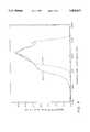
- FIG. 4is a graph showing a gradient coating and an extended and improved gradient coating deposited in accordance with the teachings of the invention.
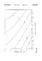
- FIG. 5is a graph showing the effect of coating apparatus height from the surface of a glass substrate and carrier flow on the ratio of tin oxide to silicon oxide in the coating deposited on the glass substrate in accordance with the teachings of the invention.
- FIG. 6is a graph showing the effect on film thickness using the accelerants of the instant invention.
- the article 10includes a substrate 12, e.g. but not limiting to the invention, plastic and/or clear or colored glass, having a coating 14 that exhibits minimum reflected color by having a continually varying refractive index, and preferably has an emissivity lower than the uncoated substrate.
- the substrateis a glass substrate.
- the coating 14, in general,is composed of a mixture of silicon oxide and a metal oxide, such as tin oxide. As with Zaromb, discussed above, the coating 14 has a continuously changing composition as the distance from the glass-coating interface 16 increases.
- the coatingis predominantly silicon oxide, while at the opposite surface 18 of the coating 14 e.g. the coating surface farthest from the glass-coating interface 16,, the composition of the coating is predominantly tin oxide.
- the predominantly tin oxide regionmay continue as predominantly tin oxide for a thickness required by the use of the article. For example when an article having a high emissivity is desired e.g. close to the emissivity of the glass substrate, the predominantly tin oxide region is thin; when an article having a low emissivity is desired, the predominantly tin oxide region is thicker.
- the tin oxide regionmay be doped with fluorine or antimony as taught in U.S. Pat. No.
- the coating 14is composed of continuously varying amounts of silicon oxide and tin oxide as the distance from the glass-coating interface 16 increases.
- each succeeding region of the continuously varying composition in the coating 14contains a tin oxide to silicon oxide weight percent ratio different than the preceding region and although not limiting to the invention, usually that ratio tends to increase as the distance from glass-coating interface 16 increases.
- the opposite surface 18is predominantly tin oxide, i.e., the weight percent of silicon oxide in the outermost region approaches zero, and the weight percent of tin oxide approaches 100.
- the coating 14was discussed using a coating of tin oxide and silicon oxide, the invention is not limited thereto and as will be appreciated from the discussion below any two or more metal oxides may be used in the practice of the invention.
- the coated article 10 of FIG. 1was produced using coating system 19 shown in FIG. 2.
- a discussion of coating apparatus 20 in FIG. 3will now be presented for a better appreciation of the features of the coating system 19 shown in FIG. 2.
- the apparatus 20 of FIG. 3may be used to deposit a non-homogeneous coating of the type discussed above on the glass substrate 12.
- the substrate 12is a glass ribbon 22 or pieces cut therefrom.
- coating apparatus 20is supported in any convenient manner above and spaced from the glass ribbon 22 supported on a pool or bath 24 of molten metal contained in a chamber having a non-oxidizing atmosphere, not shown, e.g. of the type of chamber taught in U.S. Pat. No. 4,853,257 whose teachings are hereby incorporated by reference.
- the glass ribbon 22moves from left to right beneath the coating apparatus 20 e.g. through a coating position.
- the inventionis not limited to the chamber, not shown, containing the pool of molten metal, nor to a non-oxidizing atmosphere and any chamber design having any type of atmosphere as well as other processes for moving a heated substrate past a coating apparatus embodying features of the invention may be used in the practice of the invention.
- the ribbon 22has a thickness range from about 0.08 inch to about 0.50 inch (about 2 to about 13 millimeters) and moves at speeds of about 700 to about 100 inches (about 17.80 meters to about 2.54 meters) per minute, respectively.
- the molten tin bath 24has a temperature in the range of about 1000° F. (538° C.) to about 2000° F. (1094° C.).
- the apparatus 20includes an elongated coating unit 25, two elongated exhausts 28 and 26, one on each side of the coating unit 25, and two elongated discharge units 31 axed 32, one on each outboard side of an exhaust as shown in FIG. 3.
- the term "elongated” as used hereinmeans that the coating unit, exhausts and discharge units extend across the width of the ribbon i.e. transverse to the movement of the ribbon 22.
- the discharge units 31 and 32provide an inert gas curtain to prevent the coating vapors from the coating zone, i.e. the zone between the discharge units 31 and 32, from moving into the chamber atmosphere and also to prevent the chamber atmosphere from moving into the coating zone.
- the separation between the coating zone and chamber atmosphereis required because the atmosphere in the coating zone as will be discussed is an oxidizing atmosphere, and the chamber atmosphere as discussed above is a non-oxidizing atmosphere.
- the inert gaswas nitrogen.
- the exhausts 26 and 28 in accordance with the teachings of the inventionare not equally spaced from the coating unit 25. More particularly, with the glass ribbon moving from left to right as shown in FIG. 3, the exhaust 28 is closer to the coating unit 25 than the exhaust 26. By positioning the exhausts at different distances from the coating unit the coating vapors are in contact with the ribbon surface for different periods of time. Therefore, all other parameters being equal, e.g., glass temperature, spacing between the coating unit and glass ribbon surface and exhaust pressures, a thicker coating will be deposited on the ribbon as it passes between the exhaust 26 and the coating unit 25, than between the coating unit 25 and the exhaust 28. This feature of the invention will be more fully appreciated in the discussion of the coating system 19 shown in FIG. 2.
- the design of the discharge units 31 and 32, the exhausts 26 and 28 and coating unit 25are not limiting to the invention.
- the inventionhas been practiced using the exhausts 26 and 28 with an elongated opening 36 connected to a collection chamber 38 and using the discharge units 31 and 32 with an elongated opening 50 connected to a discharge chamber 46.
- the inert gashas uniform pressure and constant velocity along the length of the opening 50 to provide a curtain of inert gas, a portion of which flows into the chamber (not shown) atmosphere and a portion toward the adjacent exhaust 26 or 28 as shown in FIG. 3.
- the coating unit 25includes a discharge chamber 56.
- the coating vaporexits the chamber 56 by way of elongated opening 58 and is directed toward the surface of the glass ribbon 22 passing beneath the opening 58.
- the coating vaporhas a uniform pressure and constant velocity along the length of the opening 58 and has sufficient pressure to allow a portion of the coating vapor to flow upstream and a portion to flow downstream as viewed in FIG. 3.
- each discharge unit 31 and 32ranges from about 20 to about 300 standard cubic feet per minute for a ribbon having a width of about 160 inches (4.06 meters).
- the flow rate of the nitrogenis not limiting to the invention; however, it should be sufficient to provide an inert curtain separating the coating zone and the chamber atmosphere.
- the openings 36 of the exhausts 26 and 28 and the exhaust pressureis adjusted to exhaust a portion of the inert gas from the adjacent discharge unit 31 and 32, respectively, and a portion of the coating vapor from the coating unit 25.
- the exhaust 26is spaced further from the coating unit 25 than the exhaust 28.
- the coating system 19was used to apply the coating 14 of the coated article 10 shown in FIG. 1.
- the coating system 19includes a costing station 59 for applying a compositionally graded coating and coating station 60 for extending the thickness of the predominantly tin oxide region at the surface 18 of the coating 14 (see FIG. 1).
- the coating station 59includes coating units 61, 62 and 64, exhausts 66, 68,, 70 and 72 and discharge units 31 and 32.
- the coating station 60is not limiting to the invention; however the coating station used in the practice of the invention was the type of coating apparatus disclosed in U.S. Pat. No. 4,853,257 which teachings are hereby incorporated by reference.
- Opening 50 of the discharge unit 31is spaced about 25 inches (63.5 centimeters) from opening 50 of the discharge unit 32; opening 74 of the exhaust 66 is spaced about 221/2 inches (57 centimeters) from the opening 50 of the discharge unit 32; opening 76 of the coating unit 61 is spaced about 20 inches (51 centimeters) from the opening 50 of the discharge unit 32; opening 78 of the exhaust 68 is spaced 171/2 inches (44.5 centimeters) from the opening 50 of the discharge unit 32; opening 80 of the coating unit 62 is spaced about 121/2 inches (32 centimeters) from the opening 50 of the discharge unit 32; opening 82 of the exhaust 70 is spaced about 10 inches (25.4 centimeters) from the opening 50 of the discharge unit 32; opening 84 of the coating unit 64 is spaced about 5 inches (12.7 centimeters) from the opening 50 of the discharge unit 32, and opening 86 of the exhaust 72 is spaced about 21/2 inches (6 centimeters) from the opening 50 of the discharge unit 32.
- the coating station 60
- the openings 50, 74, 76, 78, 80, 82, 84, and 86were spaced, in a convenient manner, about 0.2 inches (0.51 centimeter) above the upper surface of the glass ribbon 22 as viewed in FIG. 2.
- the length of the openings 50was about 25 inches (64 centimeters); the length of the openings 74, 78, 82 and 86 was about 25 inches (64 centimeters) and the length of the openings 76, 80 and 84 was about 21 inches (53.34 centimeters).
- the width of the openings 50was about 0.125 inch (0.32 centimeter); the width of the openings 74, 78, 82 and 86 was about 0.250 inch (0.64 centimeter) and the width of the openings 76, 80 and 84 was about 0.06 inch (0.15 centimeter).
- the flows of nitrogen and coating vaporwere about 350 to about 700 SLPM (standard liters per minute).
- the exhaust flowwas about 375 to about 770 SLPM.
- the glass ribbon speedswere between about 200-700 inches (5.08-17.78 meters) per minute, the temperature of the glass ribbon moving into, through and out of the coating stations 59 and 60 was between about 1170°-1250° F. (635°-675° C.).
- the coating system 19 and in particular the coating station 59 and the method associated therewithare especially effective for the chemical vapor deposition (CVD) of coatings from mixtures of silicon and metal containing precursors to provide the article 10 shown in FIG. 1.
- CVDchemical vapor deposition
- the coating 14is made from a mixture of tin containing precursors and silicon containing precursors capable of being volatilized and converted to their corresponding oxides in the presence of oxygen at temperatures in the range of about 750° to about 1500° F. (about 400° C. to about 815° C.).
- the inventionis not limited thereto and other metal containing precursors may be used with the coating apparatus and in the coating processes discussed above.
- Compounds that have been used in the practice of the inventioninclude diethylsilane, tetramethoxysilane, tetraethoxysilane, tetraisopropoxysilane, diethyldichlorosilane, tetramethylcyclotetrasiloxane and triethoxysilane.
- the inventioncontemplates silicon containing precursors that can be converted to their corresponding silicon oxides and can be used in admixture with the metal containing precursors to form the desired coating on a substrate e.g. a glass substrate having a coating with the desired mixed oxide gradient.
- the functional groups that are capable of giving the silicon containing precursor containing an Si--O bond the ability to be easily converted to a silicon oxide coatinginclude hydrogen, halogens, vinyls and ⁇ -chlorinated alkyls.
- the reactivity of the silicon containing precursorcan then be tailored by the appropriate choice of functional groups.
- the silicon containing precursor of the instant inventionis not limited to having only the above-defined substituents thereon.
- alkylor substituted alkyl, radicals having from 1 to 10, preferably 1 to 4, carbon atoms, such as --CH 3 ,--CH 2 CH 2 CH 3 and --CH 2 CH 2 OH;
- halogenated or perhalogenated alkyl radicalshaving from 1 to 10, preferably 1 to 4, carbon atoms, such as --CCOl 3 , --CH 2 CHClCH 3 and --CH 2 CCl 2 CCl 3 ;
- alkenyl or substituted alkenyl radicalshaving from 2 to 10, preferably 2 to 4, carbon atoms, such as --CH ⁇ CHCH 3 and --CH ⁇ CH 2 ;
- alkynyl or substituted alkynyl radicalshaving from 2 to 10, preferably 2 to 4, carbon atoms, such as --C.tbd.C--CH 3 and --C.tbd.CH; and
- aryl or aralkyl or substituted aryl or aralkyl radicalshaving from 6 to 11, preferably 6 to 9, carbon atoms, such as --C 6 H 5 and --C 6 H 4 CH 3 ;
- R 2are functional groups that form a bond with the Si atom which is easily thermally broken e.g. at temperatures between about 200° F.-800° F. (about 93.5° C.-445° C.) and preferably between about 400° F.-700° F. (205° C.-370° C.).
- the functional group (R 2 ) capable of giving the silicon containing precursor the ability to be easily converted to a silicon oxide coatingis selected from Group B consisting of:
- halogenpreferably Cl
- R 3is a bridging group to provide for multiple silicon atom compounds.
- R 3is selected from Group C consisting of: ##STR5## wherein R 5 is an alkyl or substituted alkyl radical having from 1 to 10, preferably 1 to 4, carbon atoms, such as ##STR6## where n is 1 to 10 preferably 1 to 4, and wherein R 4 completes the bonding on the foundation silicon atom.
- R 4is selected from the Groups A and B above and the following Group D consisting of:
- alkoxide or substituted alkoxide radicalshaving from 1 to 10, preferably 1 to 4, carbon atoms, such as --OCH 2 CH 3 ;
- alkyl or substituted alkyl radicalshaving from 1 to 10, preferably 1 to 5, carbon atoms, such as --CH 2 CH 3 ;
- alkylphosphinesand dialkylphosphines, wherein the alkyl radical has from 1 to 10, preferably 1 to 4, carbon atoms, such as --PHCH 3 and --P(CH 2 CH 3 ) 2 .
- Substituents for Groups A, B and D discussed above,can be selected from following Group E consisting of:
- alkoxide radicalhaving from 1 to 10, preferably 1 to 4, carbon atoms, such as --OCH 2 CH 2 CH 2 CH 3 ;
- alkyl radicalhaving from 1 to 10, preferably 1 to 4, carbon atoms, such as --CH 2 CH 2 CH 3 ;
- halogen or a halogenated alkyl radicalhaving from 0 to 10, preferably 0 to 4, carbon atoms, such as Cl or --CCl 3 ;
- alkenyl radicalhaving from 2 to 10, preferably 2 to 4, carbon atoms, such as --CH ⁇ CH 2 ;
- alkynyl radicalhaving from 2 to 10, preferably 2 to 4, carbon atoms, such as --C.tbd.CH;
- an aryl or aralkyl radicalhaving from 6 to 11, preferably 6 to 9, carbon atoms, such as --C 6 H 5 ;
- alkylphosphinealkylphosphine, and dialkyl phosphine radicals, wherein the alkyl group has from 1 to 10, preferably 1 to 4, carbon atoms, such as --PH 2 , --PHCH 3 , --P(CH 2 CH 3 ) 2 , and --OH.
- R 3can be selected from Groups A, B or D.
- R 3is a bridging group. In the multi-silicon atom molecule case, R 3 connects two silicon atoms directly.
- R 4is not present on any of the silicon atoms.
- the R 4 groupsare present only on the silicon atoms in the terminating position in the chain.
- the bridging groups, R 3can be the same or different.
- R 1is no longer selected from Group A and is instead another silicon bearing group from base structure I with the continued requirement of having an R 2 selected from Group B.
- the bonding between the silicon bearing groupsis chosen so that a direct Si--O--Si bond is formed.
- R 4is only present on the terminating silicon atoms as described above.
- R 3can now be selected from Groups A, B, C or D. By selecting R 3 from Group C we can create multi-silicon atom molecules with different bridging groups, i.e., Si--O--Si--N--Si.
- Specific compounds that have been used in the practice of the inventioninclude tetramethylcyclotetrasiloxane, tetramethyldisiloxane and triethoxysilane.
- Specific compounds that may be used in the practice of the invention, but not limiting thereto,are methyldimethoxysilane, dimethylmethoxysilane, trimethoxysilane, dimethylchloromethoxysilane, methylchlorodimethoxysilane, chlorotrimethoxysilane, dichlorodimethoxysilane, trichloromethoxysilane, triethoxysilylacetylene, trimethylpropynylsilane, tetramethyldisiloxane, tetramethyldichlorodisiloxane, tetramethylcyclotetrasiloxane, triethoxysilane, chlorotriethoxysilane, pentachloroethyltriethoxysilane and
- Metal containing precursors that can be used in admixture with the silicon containing precursors defined above in the chemical vapor deposition of mixed oxides on a glass substrateinclude metal containing precursors that are vaporizable at or below about 500° F. (260° C.) and that will react with an oxygen-containing gas to form the corresponding metal oxides.
- compounds that may be usedinclude organometallic compounds containing metals including but not limited to titanium, vanadium, chromium, manganese, iron, cobalt, nickel, copper, zinc, gallium, germanium, arsenic, selenium, yttrium, zirconium, niobium, molybdenum, cadmium, rhodium, ruthenium, palladium, indium, antimony, tellurium, tantalum, tungsten, platinum, lead, bismuth, aluminum, and tin. Of these metal compounds, tin compounds are most preferred.
- tin compounds useable hereininclude those defined by the following structural formula II: ##STR7## wherein R 6 , R 7 , R 8 , and R 9 are the same or different and include but are not limited to halogens preferably Cl or F, an alkyl radical having from 1 to 10, preferably 1 to 4, carbon atoms, such as --CH 3 , an aryl group having from 6 to 11, preferably 6 to 9, carbon atoms, such as --C 6 H 5 .
- any other organic or inorganic functional groupcan be used provided the vapor pressure of the resultant compound is at least 0.01 pounds per square inch absolute, below about 500° F. (260° C.).
- the silicon containing precursors defined above, including those bearing the Si--O bond,can be used alone, or they can be used in admixture with the organometallic compounds discussed above in the chemical vapor deposition of the corresponding single or mixed oxides on a glass substrate.
- the silicon containing precursorwhen used alone, or in admixture with other metal containing precursors, in the chemical vapor deposition of single or mixed oxides onto a moving substrate e.g. coating a ribbon of glass advancing along a molten metal bath or on a conveyor, it is desirable to have a rate of silicon oxide deposition sufficient to coat the moving glass substrate. For example, when coating an advancing glass ribbon and the deposition rate of silicon oxide is relatively low, the glass ribbon speed has to be reduced.
- the rate of deposition of all classes of silicon containing precursors used in the chemical vapor deposition processeshas to be increased to attain a uniform coating.
- a number of materialshave been identified that can be used to accelerate the deposition rate of silicon oxides from their precursors.
- the type and functionality of each accelerantdepends to some extent on the silicon containing precursors with which it will be used. Combinations have been determined for a specific coated article and for the process used to deposit the desired coating, in particular, the mixed oxide of the invention. It has further been determined that a synergistic effect occurs between certain combinations of precursors and accelerants that result in a beneficial altering and control of the morphology of the coating.
- Accelerants that can be used in the practice of the invention to increase the deposition rate of silicon oxide alone or in combination with another oxide, for example, tin oxidecan be defined as follows:
- Lewis Acidssuch as trifluoroacetic acid and hydrochloric acid.
- Lewis Basessuch as NaOH, NaF, CH 3 OH, CH 3 OCH 3 and S(CH 3 CH 2 ) 2 .
- halogenspreferably Cl
- alkenyl or substituted alkenyl radicalshaving from 2 to 10, preferably 2 to 4, carbon atoms, such as --CH ⁇ CH 2 ;
- perhalogenated alkyl or substituted alkyl radicalshaving from 1 to 10, preferably 1 to 4, carbon atoms, such as --CClH 2 or halogenated alkyl or substituted alkyl radicals having from 1 to 10, preferably 1 to 4, carbon atoms, such as --CCl 2 CH 2 CH 3 ;
- acyloxy radicalshaving from 1 to 10, preferably 1 to 4, carbon atoms, such as --OCOCH 3 ;
- alkynyl or substituted alkynyl radicalshaving from 2 to 10, preferably 2 to 4, carbon atoms, such as --C.tbd.CH;
- alkyl or substituted alkyl radicalshaving from 1 to 10, preferably 1 to 4, carbon atoms, such as --CH 3 , --CH 2 CH 2 CH 3 ;
- aryl or substituted aryl radicalshaving from 6 to 10, preferably 6 to 9, carbon atoms, such as --C 6 H 4 CH 3 ;
- alkoxide or substituted alkoxide radicalshaving from 1 to 10, preferably 1 to 4, carbon atoms, such as --OCH 2 CH 2 CH 3 ;
- substituentsare from Group E discussed above, examples of which compounds include but are not limited to triethylphosphite, trimethylphosphite, trimethylborate, PF 5 , PCl 3 , PBr 3 , PCl 5 , BCl 3 , BF 3 , (CH 3 ) 2 BBr, SF 4 and HO 3 SF.
- triethylphosphitewas used.
- halogenspreferably Cl
- R 17is a linear, branched or substituted alkyl radical having from 1 to 10 carbon atoms, preferably 1 to 4, with substituents selected from Group E discussed above;
- R 19 --N--R 20wherein R 19 and R 20 are linear or branched alkyl groups, or substituted alkyl groups having from 1 to 10, preferably 1 to 4, carbon atoms, with substituents selected from Group E discussed above; (less the phosphine groups, such as --PH 2 ); and
- R 21forms cyclic group having from 2 to 10 preferably 2 to 6 carbon atoms, with substituents selected from Group E discussed above (less the phosphine groups).
- a moving glass substratewas coated using the same precursor chemistry as used in Run Nos. 11 and 12 of Table 2 and similar deposition rates resulted.
- the precursorswere vaporized at a temperature of about 150° F. (65° C.) to about 500° F. (260° C.), and the gaseous mixture of the precursors, oxygen containing gases, and carrier gas and accelerant, were brought into contact with a glass ribbon supported on a molten metal bath and heated to a temperature of about 950° F. (510° C.) to about 1350° F. (730° C.).
- the glass ribbonadvanced at a speed of about 170 to 730 inches (4.25 to 18.00 meters) per minute.
- the coating 14is characterized by having a continuously varying composition as the distance from the glass-coating interface 16 increases, resulting in a substantial reduction of iridescence in the coated product.
- each succeeding region of the continuously varying compositioncontains a silicon oxide to tin oxide ratio that varies as the distance from the glass-coating interface increases. More particularly, the percent of silicon oxide decreases as the percent of tin oxide increases, so that as the opposite surface 18 is reached, the region is composed predominantly of tin oxide. Thereafter the thickness of the region of predominantly tin oxide may be increased to reduce the emissivity of the coated article.
- the presence of phosphorus, aluminum and/or boronaffects the morphology of the resultant coating by decreasing the percent crystallinity (approaching 0% crystallinity) and thereby reduces the light scattering properties which can be observed as haze.
- the amount of the phosphorus, aluminum or boron compound incorporated in the layeris a function of process variables.
- a glass ribbon moving at speeds between 175 to 730 inches (425 to 1800 centimeters) per minute, and having a temperature in the range of 1180° F. (637° C.) to 1220° F. (660° C.)was coated with a gaseous mixture having a phosphorus compound as an accelerant; the mole fraction of the accelerant was 0.01 to 0.5.
- One to 12 atomic percent of phosphoruswas found dispersed in the coating.
- the inventionencompasses using an amount of accelerant greater than 0 and up to 15 atomic percent with a preferred range of 1 to 5 atomic percent.
- compositionswere prepared from silicon containing precursors and monobutyltinchloride to illustrate the increased growth rate of mixed oxide films on a glass substrate in accordance with the teachings of the invention.
- monobutyltinchloridewas used with different silicon containing precursors.
- the precursorswere vaporized, when necessary, and the resulting gaseous mixture of precursors, oxygen and nitrogen, were introduced into a quartz tube that was electrically heated and controlled to maintain a temperature of 300° F. (150° C.).
- the concentration of the silicon containing precursorswas in all instances 0.30 mole percent, the monobutyltinchloride 0.50 mole percent, oxygen 21 mole percent, with the remainder nitrogen.
- the velocity of the precursors and carrier gaswas maintained at a rate of 30 centimeters per second in the quartz tube- This gas mixture was passed over a glass substrate heated to about 1200° F. (650° C.), for 3 to 30 seconds after which the spent gas mixture was vented into a chemical hood.
- the film thickness for all the runs except Run No. 8 discussed belowwas measured using a Tencot P1 profilometer.
- the film growth ratewas calculated by dividing film thickness by the coating time. The data obtained are set forth below in Table 2.
- Run No. 1was used as the control because the diethylsilane is generally accepted as having an acceptable rate of deposition.
- Run Nos. 4, 5 and 6The tetramethylcyclotetrasiloxane precursors used in Run Nos. 4, 5 and 6 were obtained from different suppliers. Run Nos. 2, 3 and 10 using silicon containing precursors having an Si--O bond without the accelerants or the functional groups of the instant invention had an expected low growth rate. Run Nos. 4, 5, 6, 7 and 9 which had a Si--O bond with the functional group of the instant invention had a deposition rate equal to or better than the control Run No. 1. Additionally Run No. 2 when augmented with an accelerator as taught in the instant invention (see Run Nos. 11 and 12) exhibited a deposition rate greater than Run No. 2 and approaching (Run No. 12) or exceeding (Run No. 11) the deposition rate of control Run No. 1.
- Run No. 8is a compound having the Si--O bond that does not contain a functional group or accelerant of the instant invention; however, it showed a deposition rate equal to the control Run No. 1.
- the film quality of Run No. 8was extremely poor and the film thickness had to be estimated using interference colors which was different from the measuring technique used for Run Nos. 1-7 and 9-12.
- the soda-lime-silica float glass ribbon supported by and moving along a molten metal bathhad a thickness of about 0.118 inch (0.300 centimeter), a temperature of about 1200° F. (650° C.), and a line speed of 510 inches (13 meters) per minute.
- the surface of the openings of the nitrogen curtain provided by the discharge units 31 and 32 and the exhausts 26 and 28were maintained at a height of about 0.22 inch (0-55 centimeter) above the surface to be coated of the glass ribbon 22.
- the tin depth profile of a film produced on the glass ribbon using both the asymmetric and symmetric coater configurationsis shown in the graph in FIG. 4.
- the film analysiswas accomplished using the Rutherford Backscattering Spectrometry (RBS) technique for purposes of comparing the gradient film produced by the two coater configurations.
- the RBS spectra in FIG. 4were taken at a special angle in order to obtain optimum depth resolution of the tin atom distribution through the film.
- a comparison of the asymmetric coater configuration (shown by solid line 210) with that of the symmetric coater configuration (shown by dotted line 212)is shown in the RBS spectra in FIG. 4.
- the extended region of the tin signal from 2025 keV at 3.7 relative counts down to 1890 keV at 1.4 relative countsis compared to the symmetric coater which has its tin signal varying from 2025 KeVC at 3.6 relative counts down to 1940 keV at 1.4 relative counts.
- This differenceshows an increase in film thickness for an asymmetric coater configuration.
- the asymmetric coater configurationprovides the gradiant coating with an extended range of varying composition.
- the coating composition vaporwas maintained at 320° F. (165° C.) and contained 0.8 mole percent monobutyltinchloride, 0.3 mole percent tetraethoxysilane, 0.1 mole percent triethylphosphite, 0.54 mole percent water, with the balance air.
- the total gas flow and coater heightwere varied while the concentrations were held constant. The results obtained are set forth in the process contour chart in FIG. 5.
- the boundary layer conditionsare altered in the coating zone thereby altering the relative ratio of tin oxide and silicon oxide deposited.
- the process contour chartshows how these two other techniques i.e. coater height and volumetric feed, alter the coating composition on the glass substrate.
- the process chart, FIG. 6,was developed using experimental design data.
- the precursor vaporwas maintained at 320° F. (165° C.) and contained 0.8 mole percent monobutyltinchloride, 0.3 mole percent tetraethoxysilane.
- Triethylphosphite (TEP) and waterwere varied and sufficient air was added to obtain a volumetric feed rate of 500 standard liters per minute.
- the glass ribbon 22had a thickness of 0.118 inch (0.300 centimeter), a temperature of 1200° F. (650° C.) and a line speed of 510 inches (13 meters) per minute.
- the coating unit 25was maintained at a height of 0.22 inch (0.56 centimeter) above the surface of the glass ribbon. Note the substantial effect exhibited by the presence of triethylphosphite on the coating thickness. As the mole percent of triethylphosphite was increased the coating thickness increased. Increasing the mole percent of the water also increased the coating thickness.
- the article 12 of FIG. 1was produced using the coating station 59 shown in FIG. 2, in conjunction with the coating station 60 described in the teachings of Henery. Coated articles were produced at three glass thicknesses i.e. at three different glass ribbon speeds to demonstrate the flexibility of the process.
- the coating station 59was used to produce a coating that varied in composition from predominantly silicon oxide at the glass-coating interface 16 to predominantly pure tin oxide and the coating station 60 produced an extended thickness of predominantly tin oxide.
- the coating station 59had three coating units 61, 62 and with openings 76, 80 and 84 respectively, and four exhausts 66, 68, 70 and 72.
- the exhausts 66 and 68were positioned relative to the coating unit 61 in a symmetric configuration while the exhausts 68 and 70 and the exhausts 70 and 72 were arranged in an asymmetric configuration about their respective coater units 62 and 64.
- the coating station 59had two discharge units 31 and 32 each with opening 50.
- the distance between the openings 74 and 76, 76 and 78, 80 and 82, 84 and 86was about 23/4, inches (7.08 centimeters).
- the distance between the openings 80 and 78, and between 84 and 82was about 51/2 inches (14.0 centimeters).
- each of the coating units 61, 62 and 64different chemical feed rate ranges are required in each of the coating units 61, 62 and 64.
- the chemical concentrations required to produce the desired compositional changeare also a function of the speed of the glass ribbon. Examples of typical setpoints are given in Table 3.
- the carrier gaswas air, maintained at a temperature of about 320° F. (160° C.).
- the total gas flow of the discharge units 31 and 32was held at about 500 standard liters per minute.
- the coating station 59was spaced about 0.22 inches (0.59 centimeter) above the moving glass ribbon 22.
- the extended region of predominantly tin oxidewas deposited at the coating station 60 using the teachings of U.S. Pat. No. 4,853,257.
Landscapes
- Chemical & Material Sciences (AREA)
- Engineering & Computer Science (AREA)
- Chemical Kinetics & Catalysis (AREA)
- General Chemical & Material Sciences (AREA)
- Materials Engineering (AREA)
- Organic Chemistry (AREA)
- Life Sciences & Earth Sciences (AREA)
- Geochemistry & Mineralogy (AREA)
- Mechanical Engineering (AREA)
- Metallurgy (AREA)
- Inorganic Chemistry (AREA)
- Physics & Mathematics (AREA)
- Plasma & Fusion (AREA)
- Surface Treatment Of Glass (AREA)
- Chemical Vapour Deposition (AREA)
- Laminated Bodies (AREA)
- Glass Compositions (AREA)
- Paints Or Removers (AREA)
Abstract
Description
TABLE 1 ______________________________________ Mole Percent Preferred Compound Broad Range Range ______________________________________ Metal Containing Precursor 0.005 to 5.0 0.1 to 2.0 Silicon Containing Precursor 0.0001 to 5.0 0.05 to 2.0 Oxygen-Containing Gas 1.0 to 99.0 5.0 to 50.0 Accelerant 0.0001 to 10.00 0.01 to 2.0 ______________________________________
TABLE 2 ______________________________________ Growth Rate, Run No. Silicon Containing Precursors Å/Second ______________________________________ 1 diethysilane 129 2 tetraethoxysilane 43 3 di-t-butoxydiacetosilane 64 4 tetramethylcyclotetrasiloxane 181 5 tetramethylcyclotetrasiloxane 205 6 tetramethylcyclotetrasiloxane 177 7 tetramethyldisiloxane 164 8 ethyltriacetoxysilane 110* 9 triethoxysilane 139 10methyldiacetoxysilane 32 11 tetraethoxysilane + 0.31 136mole percent triethylphosphite 12 tetraethoxysilane + 0.09 87 mole percent triethylphosphite ______________________________________ *estimated
TABLE 3 __________________________________________________________________________ MBTC MBTC MBTC TEOS TEOSTEOS Sample Unit 61Unit 62Unit 64Unit 61Unit 62Cell 64 # mole % mole % mole % mole % mole % mole % __________________________________________________________________________1 0.280 0.190 0.490 0.050 0.050 0.020 2 0.290 0.300 0.600 0.100 0.160 0.300 3 0.350 0.200 0.940 0.300 0.300 0.270 4 0.400 0.200 0.940 0.300 0.300 0.330 5 0.600 0.758 0.790 0.390 0.400 0.350 6 0.500 0.600 1.200 0.265 0.300 0.100 __________________________________________________________________________ MBTC means monobutyltintrichloride TEOS means tetraethoxysilane
__________________________________________________________________________ TEP TEP TEP WATER WATER WATERSample Unit 61Unit 62Unit 64Unit 61Unit 62Cell 64 # mole % mole % mole % mole % mole % mole % __________________________________________________________________________1 0.300 0.100 0.025 0.170 0.600 0.600 2 0.280 0.110 0.039 0.180 0.330 0.630 3 0.280 0.120 0.070 0.150 0.610 0.370 4 0.280 0.100 0.050 0.150 0.610 0.370 5 0.266 0.120 0.066 0.150 0.180 0.640 6 0.400 0.300 0.288 0.400 1.000 1.000 __________________________________________________________________________ TEP means triethyphosphite
__________________________________________________________________________ GLASS GLASS COLOR Gradient Tin Oxide Sample TEMPERATURE SPEED SATURATION Thickness Thickness # °F. inches/min. INDEX Å Å __________________________________________________________________________1 1230 340 5.0 1200 4000 2 1234 340 5.0 1100 4000 3 1194 340 2.3 1250 3700 4 1200 340 3.6 1150 3650 5 1190 490 8.9 850 1750 6 1200 700 4.6 1000 1700 __________________________________________________________________________
Claims (20)
Priority Applications (5)
| Application Number | Priority Date | Filing Date | Title |
|---|---|---|---|
| US08/264,816US5464657A (en) | 1993-02-16 | 1994-06-23 | Method for coating a moving glass substrate |
| US08/464,113US5863337A (en) | 1993-02-16 | 1995-06-05 | Apparatus for coating a moving glass substrate |
| US08/472,589US5599387A (en) | 1993-02-16 | 1995-06-07 | Compounds and compositions for coating glass with silicon oxide |
| US08/678,252US5776236A (en) | 1993-02-16 | 1996-07-11 | Mixed metal oxide film having an accelerant |
| US09/057,677US7897259B1 (en) | 1993-02-16 | 1998-04-09 | Compounds and compositions for coating glass with silicon oxide |
Applications Claiming Priority (2)
| Application Number | Priority Date | Filing Date | Title |
|---|---|---|---|
| US08/017,930US5356718A (en) | 1993-02-16 | 1993-02-16 | Coating apparatus, method of coating glass, compounds and compositions for coating glasss and coated glass substrates |
| US08/264,816US5464657A (en) | 1993-02-16 | 1994-06-23 | Method for coating a moving glass substrate |
Related Parent Applications (1)
| Application Number | Title | Priority Date | Filing Date |
|---|---|---|---|
| US08/017,930DivisionUS5356718A (en) | 1993-02-16 | 1993-02-16 | Coating apparatus, method of coating glass, compounds and compositions for coating glasss and coated glass substrates |
Related Child Applications (2)
| Application Number | Title | Priority Date | Filing Date |
|---|---|---|---|
| US08/464,113Continuation-In-PartUS5863337A (en) | 1993-02-16 | 1995-06-05 | Apparatus for coating a moving glass substrate |
| US08/472,589Continuation-In-PartUS5599387A (en) | 1993-02-16 | 1995-06-07 | Compounds and compositions for coating glass with silicon oxide |
Publications (1)
| Publication Number | Publication Date |
|---|---|
| US5464657Atrue US5464657A (en) | 1995-11-07 |
Family
ID=21785328
Family Applications (2)
| Application Number | Title | Priority Date | Filing Date |
|---|---|---|---|
| US08/017,930Expired - LifetimeUS5356718A (en) | 1993-02-16 | 1993-02-16 | Coating apparatus, method of coating glass, compounds and compositions for coating glasss and coated glass substrates |
| US08/264,816Expired - LifetimeUS5464657A (en) | 1993-02-16 | 1994-06-23 | Method for coating a moving glass substrate |
Family Applications Before (1)
| Application Number | Title | Priority Date | Filing Date |
|---|---|---|---|
| US08/017,930Expired - LifetimeUS5356718A (en) | 1993-02-16 | 1993-02-16 | Coating apparatus, method of coating glass, compounds and compositions for coating glasss and coated glass substrates |
Country Status (18)
| Country | Link |
|---|---|
| US (2) | US5356718A (en) |
| EP (2) | EP1092688A1 (en) |
| JP (2) | JP3058792B2 (en) |
| KR (1) | KR970001212B1 (en) |
| CN (2) | CN1089320C (en) |
| AT (1) | ATE243173T1 (en) |
| AU (1) | AU672853B2 (en) |
| CA (1) | CA2114971C (en) |
| DE (1) | DE69432827T2 (en) |
| DK (1) | DK0611733T3 (en) |
| ES (1) | ES2201065T3 (en) |
| FI (2) | FI113759B (en) |
| MX (1) | MX9401182A (en) |
| NZ (4) | NZ280362A (en) |
| PT (1) | PT101462B (en) |
| RU (1) | RU2138453C1 (en) |
| TW (1) | TW325457B (en) |
| ZA (1) | ZA94790B (en) |
Cited By (38)
| Publication number | Priority date | Publication date | Assignee | Title |
|---|---|---|---|---|
| US5744215A (en)* | 1996-01-04 | 1998-04-28 | Ppg Industries, Inc. | Reduction of haze in transparent coatings |
| US5859154A (en)* | 1997-09-26 | 1999-01-12 | Ppg Industries, Inc. | Resinous composition of phosphatized polyester polymers and coating compositions for improved adhesion |
| US6248397B1 (en)* | 1997-11-04 | 2001-06-19 | Pilkington Plc | Method of depositing a silicon oxide coating on glass and the coated glass |
| FR2816726A1 (en)* | 2000-11-16 | 2002-05-17 | Air Liquide | Surface treatment installation has regulator to adjust flow rate of gas drawn out of chamber, so as to maintain zero pressure difference between interior and exterior of chamber |
| WO2002085809A2 (en) | 2001-02-28 | 2002-10-31 | Ppg Industries Ohio, Inc. | Photo-induced hydrophilic article and method of making same |
| US20030027000A1 (en)* | 1997-03-14 | 2003-02-06 | Greenberg Charles B. | Visible-light-responsive photoactive coating, coated article, and method of making same |
| US20030039843A1 (en)* | 1997-03-14 | 2003-02-27 | Christopher Johnson | Photoactive coating, coated article, and method of making same |
| US20030216242A1 (en)* | 1993-11-16 | 2003-11-20 | Mehran Arbab | Colored glass compositions and automotive vision panels with reduced transmitted color shift |
| US20030235720A1 (en)* | 2000-08-31 | 2003-12-25 | Athey Pat Ruzakowski | Methods of obtaining photoactive coatings and/or anatase crystalline phase of titanium oxides and articles made thereby |
| US6677063B2 (en) | 2000-08-31 | 2004-01-13 | Ppg Industries Ohio, Inc. | Methods of obtaining photoactive coatings and/or anatase crystalline phase of titanium oxides and articles made thereby |
| US20040146645A1 (en)* | 2003-01-29 | 2004-07-29 | Freeman Glenn E. | Coated article having a sealed layered edge to impede corrosion of a coating at the edge and method of making same |
| US20040241490A1 (en)* | 2003-03-28 | 2004-12-02 | Finley James J. | Substrates coated with mixtures of titanium and aluminum materials, methods for making the substrates, and cathode targets of titanium and aluminum metal |
| US20040247929A1 (en)* | 2001-10-22 | 2004-12-09 | Harry Buhay | Coating stack comprising a layer of barrier coating |
| US20050000444A1 (en)* | 2001-09-10 | 2005-01-06 | Hass Derek D | Method and apparatus application of metallic alloy coatings |
| US20050026002A1 (en)* | 2003-06-24 | 2005-02-03 | Klaus Hartig | Concentration-modulated coatings |
| US20050031876A1 (en)* | 2003-07-18 | 2005-02-10 | Songwei Lu | Nanostructured coatings and related methods |
| US20050258030A1 (en)* | 2004-04-27 | 2005-11-24 | Finley James J | Effects of methods of manufacturing sputtering targets on characteristics of coatings |
| US20060029754A1 (en)* | 2004-08-05 | 2006-02-09 | Medwick Paul A | Coated substrate with improved solar control properties |
| US20060029813A1 (en)* | 2004-08-09 | 2006-02-09 | Kutilek Luke A | Coated substrates that include an undercoating |
| US20060046089A1 (en)* | 2004-09-01 | 2006-03-02 | O'shaughnessy Dennis J | Metal based coating composition and related coated substrates |
| US20060081993A1 (en)* | 2004-10-14 | 2006-04-20 | Thiel James P | High luminance coated glass |
| US20060134322A1 (en)* | 2004-12-20 | 2006-06-22 | Harris Caroline S | Substrates coated with a polycrystalline functional coating |
| US20060210810A1 (en)* | 2005-03-21 | 2006-09-21 | Harris Caroline S | Substrates coated with a multi-film functional coating |
| US20060210809A1 (en)* | 2005-03-21 | 2006-09-21 | Finley James J | Coating composition with solar properties |
| US20070025000A1 (en)* | 2005-07-29 | 2007-02-01 | Chia-Cheng Lin | Simulated high refractive index glass |
| US20070184291A1 (en)* | 2006-02-08 | 2007-08-09 | Harris Caroline S | Coated substrates having undercoating layers that exhibit improved photocatalytic activity |
| US20070236798A1 (en)* | 2006-04-05 | 2007-10-11 | Shelestak Larry J | Antireflective coating and substrates coated therewith |
| US20100124643A1 (en)* | 2008-11-19 | 2010-05-20 | Ppg Industries Ohio, Inc. | Undercoating layers providing improved photoactive topcoat functionality |
| US20100124642A1 (en)* | 2008-11-19 | 2010-05-20 | Ppg Industries Ohio, Inc. | Undercoating layers providing improved conductive topcoat functionality |
| US20110146767A1 (en)* | 2009-12-21 | 2011-06-23 | Ppg Industries Ohio, Inc. | Silicon thin film solar cell having improved haze and methods of making the same |
| US20110146768A1 (en)* | 2009-12-21 | 2011-06-23 | Ppg Industries Ohio, Inc. | Silicon thin film solar cell having improved underlayer coating |
| US7998586B2 (en) | 2008-11-19 | 2011-08-16 | Ppg Industries Ohio, Inc. | Undercoating layers providing improved topcoat functionality |
| DE112009003493T5 (en) | 2008-11-19 | 2012-09-06 | Ppg Industries Ohio, Inc. | Primer layers conferring improved overcoat functionality |
| FR2983350A1 (en)* | 2011-11-30 | 2013-05-31 | Saint Gobain | TRANSPARENT ELECTRODE FOR CDTE PHOTOVOLTAIC CELL |
| US8679580B2 (en) | 2003-07-18 | 2014-03-25 | Ppg Industries Ohio, Inc. | Nanostructured coatings and related methods |
| US8734903B2 (en) | 2011-09-19 | 2014-05-27 | Pilkington Group Limited | Process for forming a silica coating on a glass substrate |
| US9366783B2 (en) | 2009-12-21 | 2016-06-14 | Ppg Industries Ohio, Inc. | Silicon thin film solar cell having improved underlayer coating |
| US9540277B2 (en) | 2011-03-23 | 2017-01-10 | Pilkington Group Limited | Apparatus for depositing thin film coatings and method of deposition utilizing such apparatus |
Families Citing this family (57)
| Publication number | Priority date | Publication date | Assignee | Title |
|---|---|---|---|---|
| US7897259B1 (en)* | 1993-02-16 | 2011-03-01 | Ppg Industries Ohio, Inc. | Compounds and compositions for coating glass with silicon oxide |
| US5811191A (en)* | 1994-12-27 | 1998-09-22 | Ppg Industries, Inc. | Multilayer antireflective coating with a graded base layer |
| US5738920A (en)* | 1996-01-30 | 1998-04-14 | Becton, Dickinson And Company | Blood collection tube assembly |
| US5882368A (en)* | 1997-02-07 | 1999-03-16 | Vidrio Piiano De Mexico, S.A. De C.V. | Method for coating glass substrates by ultrasonic nebulization of solutions |
| GB9710547D0 (en)* | 1997-05-23 | 1997-07-16 | Pilkington Plc | Coating method |
| JP3173426B2 (en) | 1997-06-09 | 2001-06-04 | 日本電気株式会社 | Method for manufacturing silica insulating film and method for manufacturing semiconductor device |
| US6289641B1 (en) | 1998-01-30 | 2001-09-18 | Ppg Industries Ohio, Inc. | Glazing unit having three or more spaced sheets and a single spacer frame and method of making same |
| US6115989A (en)* | 1998-01-30 | 2000-09-12 | Ppg Industries Ohio, Inc. | Multi-sheet glazing unit and method of making same |
| AU740335B2 (en) | 1998-01-30 | 2001-11-01 | Ppg Industries Ohio, Inc. | Multi-sheet glazing unit and method of making same |
| US6797388B1 (en) | 1999-03-18 | 2004-09-28 | Ppg Industries Ohio, Inc. | Methods of making low haze coatings and the coatings and coated articles made thereby |
| US6753047B1 (en)* | 1999-06-10 | 2004-06-22 | Ppg Industries Ohio, Inc. | Electrodes for liquid crystal cells |
| US6849328B1 (en) | 1999-07-02 | 2005-02-01 | Ppg Industries Ohio, Inc. | Light-transmitting and/or coated article with removable protective coating and methods of making the same |
| LU90432B1 (en) | 1999-09-01 | 2001-03-02 | Glaverbel | Pyrolytic phosphostannate or borostannate layer and glazing comprising this layer |
| US6413579B1 (en) | 2000-01-27 | 2002-07-02 | Libbey-Owens-Ford Co. | Temperature control of CVD method for reduced haze |
| US7361404B2 (en) | 2000-05-10 | 2008-04-22 | Ppg Industries Ohio, Inc. | Coated article with removable protective coating and related methods |
| GB0021396D0 (en)* | 2000-09-01 | 2000-10-18 | Pilkington Plc | Process for coating glass |
| KR100815009B1 (en) | 2000-09-28 | 2008-03-18 | 프레지던트 앤드 펠로우즈 오브 하바드 칼리지 | Precipitation Using Vapors of Oxides, Silicates and Phosphates |
| DE10063180A1 (en)* | 2000-12-18 | 2002-06-27 | Bayer Ag | Device for generating light signals |
| US7998602B2 (en)* | 2003-05-30 | 2011-08-16 | Ppg Industries Ohio, Inc. | Appliance with coated transparency |
| US7294404B2 (en) | 2003-12-22 | 2007-11-13 | Cardinal Cg Company | Graded photocatalytic coatings |
| CA2573428C (en) | 2004-07-12 | 2008-04-01 | Cardinal Cg Company | Low-maintenance coatings |
| US20090258222A1 (en)* | 2004-11-08 | 2009-10-15 | Agc Flat Glass Europe S.A. | Glazing panel |
| US8092660B2 (en) | 2004-12-03 | 2012-01-10 | Cardinal Cg Company | Methods and equipment for depositing hydrophilic coatings, and deposition technologies for thin films |
| US7923114B2 (en) | 2004-12-03 | 2011-04-12 | Cardinal Cg Company | Hydrophilic coatings, methods for depositing hydrophilic coatings, and improved deposition technology for thin films |
| AU2005315564B2 (en)* | 2004-12-16 | 2011-04-21 | Agc Glass Europe | Substrate with antimicrobial properties |
| CN1854242B (en)* | 2005-04-26 | 2012-08-29 | 李其灵 | Total spectral energy-saving light |
| US8153282B2 (en)* | 2005-11-22 | 2012-04-10 | Guardian Industries Corp. | Solar cell with antireflective coating with graded layer including mixture of titanium oxide and silicon oxide |
| JP5129975B2 (en) | 2006-04-11 | 2013-01-30 | 日本板硝子株式会社 | Photocatalytic coating with improved low maintenance properties |
| JP2009534563A (en) | 2006-04-19 | 2009-09-24 | 日本板硝子株式会社 | Opposing functional coating with equivalent single surface reflectivity |
| US20080011599A1 (en) | 2006-07-12 | 2008-01-17 | Brabender Dennis M | Sputtering apparatus including novel target mounting and/or control |
| US20080026147A1 (en)* | 2006-07-28 | 2008-01-31 | Gulbrandsen Chemicals, Inc. | Method and formulation for depositing a metal-containing coating on a substrate |
| US8728634B2 (en)* | 2007-06-13 | 2014-05-20 | Ppg Industries Ohio, Inc. | Appliance transparency |
| KR101512166B1 (en) | 2007-09-14 | 2015-04-14 | 카디날 씨지 컴퍼니 | Easy-to-manage coating technology |
| KR100889949B1 (en)* | 2008-04-10 | 2009-03-20 | 주식회사 엠엠테크 | Top-down substrate thinning device and thinning system using same |
| US8197940B2 (en)* | 2008-07-25 | 2012-06-12 | Ppg Industries Ohio, Inc. | Aqueous suspension for pyrolytic spray coating |
| US8062706B2 (en) | 2009-03-31 | 2011-11-22 | Ppg Industries Ohio, Inc. | Recovery of monobutyltin trichloride |
| RU2397572C1 (en)* | 2009-06-25 | 2010-08-20 | Учреждение Российской Академии Наук Институт Общей И Неорганической Химии Им. Н.С. Курнакова Ран (Ионх Ран) | Method of obtaining film coatings of tin oxide on substrates |
| US8557328B2 (en)* | 2009-10-02 | 2013-10-15 | Ppg Industries Ohio, Inc. | Non-orthogonal coater geometry for improved coatings on a substrate |
| FR2956659B1 (en) | 2010-02-22 | 2014-10-10 | Saint Gobain | LAYER COATED VERTICAL SUBSTRATE WITH IMPROVED MECHANICAL STRENGTH |
| US8815402B2 (en) | 2010-03-31 | 2014-08-26 | Ppg Industries Ohio, Inc. | Mirror having reflective coatings on a first surface and an opposite second surface |
| US8551609B2 (en) | 2010-04-27 | 2013-10-08 | Ppg Industries Ohio, Inc. | Method of depositing niobium doped titania film on a substrate and the coated substrate made thereby |
| FR2962852A1 (en) | 2010-07-19 | 2012-01-20 | Saint Gobain | TRANSPARENT ELECTRODE FOR HIGH-PERFORMANCE PHOTOVOLTAIC CELL |
| CN102452797B (en)* | 2010-10-19 | 2014-08-20 | 英作纳米科技(北京)有限公司 | Method for preparing coating on inner wall of medicinal glass bottle |
| JP2014513209A (en)* | 2011-03-23 | 2014-05-29 | ピルキントン グループ リミテッド | Method of depositing zinc oxide coating by chemical vapor deposition |
| US20120275018A1 (en)* | 2011-04-29 | 2012-11-01 | Ppg Industries Ohio, Inc. | Coated glasses having a low solar factor |
| RU2610044C2 (en) | 2012-01-10 | 2017-02-07 | Ппг Индастриз Огайо, Инк. | Coated glasses with low surface resistance, smooth surface and/or low thermal emissivity factor |
| CN104136656B (en) | 2012-02-23 | 2016-11-09 | 皮尔金顿集团有限公司 | The chemical vapor deposition method of deposition of silica coatings on the glass substrate |
| US10672920B2 (en)* | 2015-03-12 | 2020-06-02 | Vitro Flat Glass Llc | Article with buffer layer |
| GB201521165D0 (en) | 2015-12-01 | 2016-01-13 | Pilkington Group Ltd | Method for depositing a coating |
| WO2017137773A1 (en)* | 2016-02-12 | 2017-08-17 | Pilkington Group Limited | Chemical vapor deposition process for depositing a mixed metal oxide coating and the coated article formed thereby |
| CA2920646A1 (en)* | 2016-02-12 | 2017-08-12 | Seastar Chemicals Inc. | Organometallic compound and method |
| EP3541762B1 (en) | 2016-11-17 | 2022-03-02 | Cardinal CG Company | Static-dissipative coating technology |
| EP3676416A1 (en)* | 2017-08-31 | 2020-07-08 | Pilkington Group Limited | Chemical vapor deposition process for forming a silicon oxide coating |
| CN113167925A (en)* | 2018-11-20 | 2021-07-23 | 康宁公司 | Organosilicate films for inhibiting glass weathering |
| KR102277769B1 (en)* | 2018-11-23 | 2021-07-15 | 주식회사 엘지화학 | Silica Glass Layer |
| WO2023057756A1 (en)* | 2021-10-06 | 2023-04-13 | Pilkington Group Limited | Method of forming a silicon oxide coating |
| FR3147295A1 (en)* | 2023-03-31 | 2024-10-04 | Safran Ceramics | Process for forming a coating by chemical vapor deposition |
Citations (26)
| Publication number | Priority date | Publication date | Assignee | Title |
|---|---|---|---|---|
| US3378396A (en)* | 1967-03-27 | 1968-04-16 | Zaromb Solomon | Conductive oxide-coated articles |
| US3674453A (en)* | 1968-08-16 | 1972-07-04 | Pilkington Brothers Ltd | Production of float glass having an oxidized metal-modified surface |
| US3681042A (en)* | 1970-03-24 | 1972-08-01 | Pilkington Brothers Ltd | Coating of glass on a molten metal bath |
| US4146657A (en)* | 1976-11-01 | 1979-03-27 | Gordon Roy G | Method of depositing electrically conductive, infra-red reflective, transparent coatings of stannic oxide |
| US4187336A (en)* | 1977-04-04 | 1980-02-05 | Gordon Roy G | Non-iridescent glass structures |
| GB2031756A (en)* | 1978-10-20 | 1980-04-30 | Gordon Roy Gerald | Non-iridescent glass structures and processes for their production |
| US4206252A (en)* | 1977-04-04 | 1980-06-03 | Gordon Roy G | Deposition method for coating glass and the like |
| US4265974A (en)* | 1976-11-01 | 1981-05-05 | Gordon Roy G | Electrically conductive, infrared reflective, transparent coatings of stannic oxide |
| US4308316A (en)* | 1977-04-04 | 1981-12-29 | Gordon Roy G | Non-iridescent glass structures |
| US4377613A (en)* | 1981-09-14 | 1983-03-22 | Gordon Roy G | Non-iridescent glass structures |
| US4386117A (en)* | 1981-11-20 | 1983-05-31 | Gordon Roy G | Coating process using alkoxy substituted silicon-bearing reactant |
| US4419386A (en)* | 1981-09-14 | 1983-12-06 | Gordon Roy G | Non-iridescent glass structures |
| US4440822A (en)* | 1977-04-04 | 1984-04-03 | Gordon Roy G | Non-iridescent glass structures |
| US4468420A (en)* | 1983-07-14 | 1984-08-28 | Nippon Sheet Glass Co., Ltd. | Method for making a silicon dioxide coating |
| US4469045A (en)* | 1975-06-11 | 1984-09-04 | Pilkington Brothers P.L.C. | Coating glass |
| EP0174727A1 (en)* | 1984-08-13 | 1986-03-19 | Pilkington Plc | Coated products |
| US4590096A (en)* | 1984-12-28 | 1986-05-20 | M&T Chemicals Inc. | Water vapor, reaction rate and deposition rate control of tin oxide film by CVD on glass |
| US4853257A (en)* | 1987-09-30 | 1989-08-01 | Ppg Industries, Inc. | Chemical vapor deposition of tin oxide on float glass in the tin bath |
| US4894352A (en)* | 1988-10-26 | 1990-01-16 | Texas Instruments Inc. | Deposition of silicon-containing films using organosilicon compounds and nitrogen trifluoride |
| US4922853A (en)* | 1989-05-16 | 1990-05-08 | Libbey-Owens-Ford Co. | Stripe coating on glass by chemical vapor deposition |
| US5168003A (en)* | 1991-06-24 | 1992-12-01 | Ford Motor Company | Step gradient anti-iridescent coatings |
| US5221352A (en)* | 1989-06-19 | 1993-06-22 | Glaverbel | Apparatus for pyrolytically forming an oxide coating on a hot glass substrate |
| AU3323093A (en)* | 1991-12-26 | 1993-07-28 | Atofina Chemicals, Inc. | Coated glass article |
| US5248545A (en)* | 1991-06-24 | 1993-09-28 | Ford Motor Company | Anti-iridescent coatings with gradient refractive index |
| US5271960A (en)* | 1991-06-24 | 1993-12-21 | Ford Motor Company | Step gradient anti-iridescent coatings |
| US5304394A (en)* | 1991-06-14 | 1994-04-19 | Saint-Gobain Vitrage International | Technique for forming, by pyrolysis in a gaseous process, a coating based essentially upon oxygen and silicon |
Family Cites Families (10)
| Publication number | Priority date | Publication date | Assignee | Title |
|---|---|---|---|---|
| DE1496572B2 (en)* | 1964-07-03 | 1970-06-11 | J.D. Möller, Optische Werke GmbH, 2000 Wedel | Process for the production of anti-glare glasses by vapor deposition of surface layers in a vacuum, in particular on spectacle lenses |
| US3652318A (en)* | 1969-11-13 | 1972-03-28 | Moeller J D Optik | Process for the production of antidazzle glass filters |
| CH643469A5 (en)* | 1981-12-22 | 1984-06-15 | Siv Soc Italiana Vetro | Installation for continuous drop on the surface of a substrate door high temperature, layer solid matter. |
| CA1332281C (en)* | 1988-09-16 | 1994-10-11 | Randall L. Bauman | Temperature controlled distributor beam for chemical vapor deposition |
| EP0386341B1 (en)* | 1989-03-07 | 1995-03-15 | Asahi Glass Company Ltd. | Laminated glass structure |
| US5090985A (en)* | 1989-10-17 | 1992-02-25 | Libbey-Owens-Ford Co. | Method for preparing vaporized reactants for chemical vapor deposition |
| FR2672518B1 (en)* | 1991-02-13 | 1995-05-05 | Saint Gobain Vitrage Int | NOZZLE WITH DISSYMMETRIC SUPPLY FOR THE FORMATION OF A COATING LAYER ON A TAPE OF GLASS, BY PYROLYSIS OF A GAS MIXTURE. |
| FR2672519B1 (en)* | 1991-02-13 | 1995-04-28 | Saint Gobain Vitrage Int | NOZZLE WITH HEAVY DOWNSTREAM HEEL, FOR DEPOSITING A COATING LAYER ON A TAPE OF GLASS, BY PYROLYSIS OF A GASEOUS MIXTURE. |
| EP0499950B1 (en)* | 1991-02-14 | 1999-10-27 | Asahi Glass Company Ltd. | Laminated glass structure |
| US5122391A (en)* | 1991-03-13 | 1992-06-16 | Watkins-Johnson Company | Method for producing highly conductive and transparent films of tin and fluorine doped indium oxide by APCVD |
- 1993
- 1993-02-16USUS08/017,930patent/US5356718A/ennot_activeExpired - Lifetime
- 1994
- 1994-01-31FIFI940451Apatent/FI113759B/enactive
- 1994-02-01NZNZ280362Apatent/NZ280362A/enunknown
- 1994-02-01NZNZ286285Apatent/NZ286285A/enunknown
- 1994-02-01NZNZ328148Apatent/NZ328148A/enunknown
- 1994-02-01NZNZ250802Apatent/NZ250802A/enunknown
- 1994-02-03AUAU54878/94Apatent/AU672853B2/ennot_activeCeased
- 1994-02-04CACA002114971Apatent/CA2114971C/ennot_activeExpired - Lifetime
- 1994-02-04ZAZA94790Apatent/ZA94790B/enunknown
- 1994-02-05TWTW083100967Apatent/TW325457B/ennot_activeIP Right Cessation
- 1994-02-10EPEP01100720Apatent/EP1092688A1/ennot_activeWithdrawn
- 1994-02-10EPEP94102016Apatent/EP0611733B1/ennot_activeExpired - Lifetime
- 1994-02-10ATAT94102016Tpatent/ATE243173T1/ennot_activeIP Right Cessation
- 1994-02-10DKDK94102016Tpatent/DK0611733T3/enactive
- 1994-02-10ESES94102016Tpatent/ES2201065T3/ennot_activeExpired - Lifetime
- 1994-02-10DEDE69432827Tpatent/DE69432827T2/ennot_activeExpired - Lifetime
- 1994-02-14RURU94004970Apatent/RU2138453C1/enactive
- 1994-02-15MXMX9401182Apatent/MX9401182A/ennot_activeIP Right Cessation
- 1994-02-15KRKR1019940002624Apatent/KR970001212B1/ennot_activeExpired - Fee Related
- 1994-02-15JPJP6018633Apatent/JP3058792B2/ennot_activeExpired - Lifetime
- 1994-02-16CNCN94101575Apatent/CN1089320C/ennot_activeExpired - Lifetime
- 1994-02-16PTPT101462Apatent/PT101462B/ennot_activeIP Right Cessation
- 1994-06-23USUS08/264,816patent/US5464657A/ennot_activeExpired - Lifetime
- 1999
- 1999-11-17JPJP32645799Apatent/JP3476724B2/ennot_activeExpired - Lifetime
- 2000
- 2000-10-12CNCNB00125989XApatent/CN1196655C/ennot_activeExpired - Lifetime
- 2001
- 2001-01-12FIFI20010073Apatent/FI114211B/enactiveIP Right Grant
Patent Citations (26)
| Publication number | Priority date | Publication date | Assignee | Title |
|---|---|---|---|---|
| US3378396A (en)* | 1967-03-27 | 1968-04-16 | Zaromb Solomon | Conductive oxide-coated articles |
| US3674453A (en)* | 1968-08-16 | 1972-07-04 | Pilkington Brothers Ltd | Production of float glass having an oxidized metal-modified surface |
| US3681042A (en)* | 1970-03-24 | 1972-08-01 | Pilkington Brothers Ltd | Coating of glass on a molten metal bath |
| US4469045A (en)* | 1975-06-11 | 1984-09-04 | Pilkington Brothers P.L.C. | Coating glass |
| US4265974A (en)* | 1976-11-01 | 1981-05-05 | Gordon Roy G | Electrically conductive, infrared reflective, transparent coatings of stannic oxide |
| US4146657A (en)* | 1976-11-01 | 1979-03-27 | Gordon Roy G | Method of depositing electrically conductive, infra-red reflective, transparent coatings of stannic oxide |
| US4440822A (en)* | 1977-04-04 | 1984-04-03 | Gordon Roy G | Non-iridescent glass structures |
| US4206252A (en)* | 1977-04-04 | 1980-06-03 | Gordon Roy G | Deposition method for coating glass and the like |
| US4308316A (en)* | 1977-04-04 | 1981-12-29 | Gordon Roy G | Non-iridescent glass structures |
| US4187336A (en)* | 1977-04-04 | 1980-02-05 | Gordon Roy G | Non-iridescent glass structures |
| GB2031756A (en)* | 1978-10-20 | 1980-04-30 | Gordon Roy Gerald | Non-iridescent glass structures and processes for their production |
| US4377613A (en)* | 1981-09-14 | 1983-03-22 | Gordon Roy G | Non-iridescent glass structures |
| US4419386A (en)* | 1981-09-14 | 1983-12-06 | Gordon Roy G | Non-iridescent glass structures |
| US4386117A (en)* | 1981-11-20 | 1983-05-31 | Gordon Roy G | Coating process using alkoxy substituted silicon-bearing reactant |
| US4468420A (en)* | 1983-07-14 | 1984-08-28 | Nippon Sheet Glass Co., Ltd. | Method for making a silicon dioxide coating |
| EP0174727A1 (en)* | 1984-08-13 | 1986-03-19 | Pilkington Plc | Coated products |
| US4590096A (en)* | 1984-12-28 | 1986-05-20 | M&T Chemicals Inc. | Water vapor, reaction rate and deposition rate control of tin oxide film by CVD on glass |
| US4853257A (en)* | 1987-09-30 | 1989-08-01 | Ppg Industries, Inc. | Chemical vapor deposition of tin oxide on float glass in the tin bath |
| US4894352A (en)* | 1988-10-26 | 1990-01-16 | Texas Instruments Inc. | Deposition of silicon-containing films using organosilicon compounds and nitrogen trifluoride |
| US4922853A (en)* | 1989-05-16 | 1990-05-08 | Libbey-Owens-Ford Co. | Stripe coating on glass by chemical vapor deposition |
| US5221352A (en)* | 1989-06-19 | 1993-06-22 | Glaverbel | Apparatus for pyrolytically forming an oxide coating on a hot glass substrate |
| US5304394A (en)* | 1991-06-14 | 1994-04-19 | Saint-Gobain Vitrage International | Technique for forming, by pyrolysis in a gaseous process, a coating based essentially upon oxygen and silicon |
| US5168003A (en)* | 1991-06-24 | 1992-12-01 | Ford Motor Company | Step gradient anti-iridescent coatings |
| US5248545A (en)* | 1991-06-24 | 1993-09-28 | Ford Motor Company | Anti-iridescent coatings with gradient refractive index |
| US5271960A (en)* | 1991-06-24 | 1993-12-21 | Ford Motor Company | Step gradient anti-iridescent coatings |
| AU3323093A (en)* | 1991-12-26 | 1993-07-28 | Atofina Chemicals, Inc. | Coated glass article |
Non-Patent Citations (45)
| Title |
|---|
| Chang, C. P. et al.; "Ion and Chemical Radical Effects on the Step Coverage of Plasma Enhanced Chemical Vapor Deposition Tetraethylorthosilicate Films"; J. Appl. Phys.; 67(4), 15 Feb. 1990 no page data is available. |
| Chang, C. P. et al.; Ion and Chemical Radical Effects on the Step Coverage of Plasma Enhanced Chemical Vapor Deposition Tetraethylorthosilicate Films ; J. Appl. Phys.; 67(4), 15 Feb. 1990 no page data is available.* |
| Chapple Sokol, J. D. et al.; A Kinetics Study of the Atmospheric Pressure CVD Reaction of Silane and Nitrous Oxide ; J. Electrochem. Soc., vol. 136, No. 10, Oct. 1989, pp. 2993 3003.* |
| Chapple-Sokol, J. D. et al.; "A Kinetics Study of the Atmospheric Pressure CVD Reaction of Silane and Nitrous Oxide"; J. Electrochem. Soc., vol. 136, No. 10, Oct. 1989, pp. 2993-3003. |
| Crowell, J. E. et al.; "Model Studies of Dielectric Thin Film Growth: Chemical Vapor Deposition of SiO2"; pp. 1864-1870 Journal and Year data are unavailable. |
| Crowell, J. E. et al.; Model Studies of Dielectric Thin Film Growth: Chemical Vapor Deposition of SiO 2 ; pp. 1864 1870 Journal and Year data are unavailable.* |
| Delperier, B. et al.; "Analysis and Modelling of Tetraethoxysilane Pyrolysis"; Journal of Analytical and Applied Pyrolysis, 13 (1988) pp. 141-149. |
| Delperier, B. et al.; Analysis and Modelling of Tetraethoxysilane Pyrolysis ; Journal of Analytical and Applied Pyrolysis, 13 (1988) pp. 141 149.* |
| Desu, S. B.; "Decomposition Chemistry of Tetraethoxysilane"; Abstrate No. 1855RNP; presented at the Fall Meeting of Electrochemical Society, Honolulu, Hi., 18-23 Oct. 1987 page data are unavailable. |
| Desu, S. B.; Decomposition Chemistry of Tetraethoxysilane ; Abstrate No. 1855RNP; presented at the Fall Meeting of Electrochemical Society, Honolulu, Hi., 18 23 Oct. 1987 page data are unavailable.* |
| Hochberg, A. K. et al.; "The LPCVD of Silicon Oxide Films below 400° C. from Liquid Sources", J. Electrochem. Soc., vol. 136, No. 6, Jun. 1989, pp. 1843-1844. |
| Hochberg, A. K. et al.; "The Use of Liquid Sources in CVD Applications: Fire Safety Considerations and Delivery Methods"; Technical Article 15 of J. C. Schumacker, a Unit of Air Products and Chemicals, Inc. Year and page data are unavailable. |
| Hochberg, A. K. et al.; The Deposition of Silicon Oxide Films at Low Temperatures from Liquid Sources Journal, Year and Page data are unavailable.* |
| Hochberg, A. K. et al.; The LPCVD of Silicon Oxide Films below 400 C. from Liquid Sources , J. Electrochem. Soc., vol. 136, No. 6, Jun. 1989, pp. 1843 1844.* |
| Hochberg, A. K. et al.; The Use of Liquid Sources in CVD Applications: Fire Safety Considerations and Delivery Methods ; Technical Article 15 of J. C. Schumacker, a Unit of Air Products and Chemicals, Inc. Year and page data are unavailable.* |
| Hochberg, Dr. A. et al.; "User's Guide For: Glass Deposition with LTO-410™ Source Material" Journal, Year and Page data are unavailable. |
| Hochberg, Dr. A. et al.; User s Guide For: Glass Deposition with LTO 410 Source Material Journal, Year and Page data are unavailable.* |
| Inoue, K. et al.; "Low Temperature Growth of SiO2 Thin Film by Double-Excitation Photo-CVD"; Japanese Journal of Applied Physics; vol. 26, No. 6, Jun. 1987, pp. 805-811. |
| Inoue, K. et al.; Low Temperature Growth of SiO 2 Thin Film by Double Excitation Photo CVD ; Japanese Journal of Applied Physics; vol. 26, No. 6, Jun. 1987, pp. 805 811.* |
| J. C. Schumacher Co.,; Tetramethylcyclotetrasiloxane "Tomcats™"; Chemical & Physical Properties Journal, Year and Page data are unavailable. |
| J. C. Schumacher Co.,; Tetramethylcyclotetrasiloxane Tomcats ; Chemical & Physical Properties Journal, Year and Page data are unavailable.* |
| Lucovsky, G. et al.; "Deposition of Silicon Oxide, Nitride and Oxynitride Thin Films by Remote Plasma Enhanced Chemical Vapor Deposition"; Journal of Non-Crystalline Solids; 90 (1987) pp. 259-266. |
| Lucovsky, G. et al.; Deposition of Silicon Oxide, Nitride and Oxynitride Thin Films by Remote Plasma Enhanced Chemical Vapor Deposition ; Journal of Non Crystalline Solids; 90 (1987) pp. 259 266.* |
| Maruyama, Toshiro et al,; "Silicon Dioxide Thin Films Prepared by Chemical Vapor Deposition from Silicon Tetraacetate"; Japanese Journal of Applied Physics; vol. 28, No. 12, Dec., 1989, pp. L2253-L2254. |
| Maruyama, Toshiro et al,; Silicon Dioxide Thin Films Prepared by Chemical Vapor Deposition from Silicon Tetraacetate ; Japanese Journal of Applied Physics; vol. 28, No. 12, Dec., 1989, pp. L2253 L2254.* |
| Niwano, M. et al.; "Low-Temperature Deposition of Silicon Dioxide Films by Photoinduced Decomposition of Tetraethoxysilane"; Japanese Journal of Applied Physics; vol. 28, No. 7, Jul., 1989, pp. L1310-L1313. |
| Niwano, M. et al.; Low Temperature Deposition of Silicon Dioxide Films by Photoinduced Decomposition of Tetraethoxysilane ; Japanese Journal of Applied Physics; vol. 28, No. 7, Jul., 1989, pp. L1310 L1313.* |
| Okuhara, T. et al.; "Preparation of SiO2 Overlayers on Oxide Substrates by Chemical Vapor Deposition of Si(OC2 H5)4", Applied Surface Science 29 (1987), pp. 223-241. |
| Okuhara, T. et al.; Preparation of SiO 2 Overlayers on Oxide Substrates by Chemical Vapor Deposition of Si(OC 2 H 5 ) 4 , Applied Surface Science 29 (1987), pp. 223 241.* |
| Orfescu, C. et al.; "An Etch Rate Study on Thermally Annealed SiO2 Films Deposited in a TESO-LPCVD System"; Journal of Materials Science 25 (1990) pp. 1366-1368. |
| Orfescu, C. et al.; An Etch Rate Study on Thermally Annealed SiO 2 Films Deposited in a TESO LPCVD System ; Journal of Materials Science 25 (1990) pp. 1366 1368.* |
| Ozturk, Mehmet C. et al.; "Low-Pressure Chemical Vapor Deposition of Polycrystalline Silicon and Silicon Dioxide by Rapid Thermal Processing", Mat. Res. Soc. Symp. Proc., vol. 146, (1989) pp. 109-114. |
| Ozturk, Mehmet C. et al.; Low Pressure Chemical Vapor Deposition of Polycrystalline Silicon and Silicon Dioxide by Rapid Thermal Processing , Mat. Res. Soc. Symp. Proc., vol. 146, (1989) pp. 109 114.* |
| Pavelescu, C. et al.; "Correlations Between the Properties and the Deposition Kinetics of Low-Temperature Chemical Vapour Deposited SiO2 Films: The Effect of O2 /SiH4 Mole Ratio"; Journal of Materials Science Letters 9 (1990) pp. 143-144. |
| Pavelescu, C. et al.; Correlations Between the Properties and the Deposition Kinetics of Low Temperature Chemical Vapour Deposited SiO 2 Films: The Effect of O 2 /SiH 4 Mole Ratio ; Journal of Materials Science Letters 9 (1990) pp. 143 144.* |
| Raju, Surya K. et al.; "Analytical Model for the Low Pressure Chemical Vapor Deposition of SiO2 from Tetraethoxysilane" Journal, Year and Page data are unavailable. |
| Raju, Surya K. et al.; Analytical Model for the Low Pressure Chemical Vapor Deposition of SiO 2 from Tetraethoxysilane Journal, Year and Page data are unavailable.* |
| Strong, J.; "Practical Applications of High and Low-Reflecting Films on Glass", Le Journal De Physique Et Le Radium, Jul. 11, 1950; pp. 441-443. |
| Strong, J.; Practical Applications of High and Low Reflecting Films on Glass , Le Journal De Physique Et Le Radium, Jul. 11, 1950; pp. 441 443.* |
| Taylor, R. C. et al.; "Hexachlorodisilane as a Precursor in the LPCVD of Silicon Dioxide and Silicon Oxynitride Films"; J. Electrochem. Soc.; vol. 136, No. 8, Aug. 1989, pp. 2382-2386. |
| Taylor, R. C. et al.; Hexachlorodisilane as a Precursor in the LPCVD of Silicon Dioxide and Silicon Oxynitride Films ; J. Electrochem. Soc.; vol. 136, No. 8, Aug. 1989, pp. 2382 2386.* |
| Toyoda, Y. et al.; "Preparation of SiO2 Film by Photo-Induced Chemical Vapor Deposition Using a Deuterium Lamp and Its Annealing Effect"; Japanese Journal of Applied Physics; vol. 26, No. 6, Jun., 1987, pp. 835-840. |
| Toyoda, Y. et al.; Preparation of SiO 2 Film by Photo Induced Chemical Vapor Deposition Using a Deuterium Lamp and Its Annealing Effect ; Japanese Journal of Applied Physics; vol. 26, No. 6, Jun., 1987, pp. 835 840.* |
| Webb, Douglas A. et al.; "Silicon Dioxide Films Produced by PECVD of TEOS and TMCTS"; Proc. 2nd International ULSI Science and Technology Symposium ECS Proc. vol. 89 (9) (1989) pp. 571-578. |
| Webb, Douglas A. et al.; Silicon Dioxide Films Produced by PECVD of TEOS and TMCTS ; Proc. 2nd International ULSI Science and Technology Symposium ECS Proc. vol. 89 (9) (1989) pp. 571 578.* |
Cited By (63)
| Publication number | Priority date | Publication date | Assignee | Title |
|---|---|---|---|---|
| US7071133B2 (en) | 1993-11-16 | 2006-07-04 | Ppg Industries Ohio, Inc. | Colored glass compositions and-automotive vision panels with-reduced transmitted-color shift |
| US20030216242A1 (en)* | 1993-11-16 | 2003-11-20 | Mehran Arbab | Colored glass compositions and automotive vision panels with reduced transmitted color shift |
| US5744215A (en)* | 1996-01-04 | 1998-04-28 | Ppg Industries, Inc. | Reduction of haze in transparent coatings |
| US7096692B2 (en) | 1997-03-14 | 2006-08-29 | Ppg Industries Ohio, Inc. | Visible-light-responsive photoactive coating, coated article, and method of making same |
| US7749621B2 (en) | 1997-03-14 | 2010-07-06 | Ppg Industries Ohio, Inc. | Visible-light-responsive photoactive coating, coated article, and method of making same |
| US20030027000A1 (en)* | 1997-03-14 | 2003-02-06 | Greenberg Charles B. | Visible-light-responsive photoactive coating, coated article, and method of making same |
| US20030039843A1 (en)* | 1997-03-14 | 2003-02-27 | Christopher Johnson | Photoactive coating, coated article, and method of making same |
| US5859154A (en)* | 1997-09-26 | 1999-01-12 | Ppg Industries, Inc. | Resinous composition of phosphatized polyester polymers and coating compositions for improved adhesion |
| US6248397B1 (en)* | 1997-11-04 | 2001-06-19 | Pilkington Plc | Method of depositing a silicon oxide coating on glass and the coated glass |
| US6677063B2 (en) | 2000-08-31 | 2004-01-13 | Ppg Industries Ohio, Inc. | Methods of obtaining photoactive coatings and/or anatase crystalline phase of titanium oxides and articles made thereby |
| US20030235720A1 (en)* | 2000-08-31 | 2003-12-25 | Athey Pat Ruzakowski | Methods of obtaining photoactive coatings and/or anatase crystalline phase of titanium oxides and articles made thereby |
| US7323249B2 (en) | 2000-08-31 | 2008-01-29 | Ppg Industries Ohio, Inc. | Methods of obtaining photoactive coatings and/or anatase crystalline phase of titanium oxides and articles made thereby |
| WO2002040738A3 (en)* | 2000-11-16 | 2002-07-11 | Air Liquide | Installation wherein is performed an operation requiring control of atmosphere inside a chamber |
| FR2816726A1 (en)* | 2000-11-16 | 2002-05-17 | Air Liquide | Surface treatment installation has regulator to adjust flow rate of gas drawn out of chamber, so as to maintain zero pressure difference between interior and exterior of chamber |
| WO2002085809A2 (en) | 2001-02-28 | 2002-10-31 | Ppg Industries Ohio, Inc. | Photo-induced hydrophilic article and method of making same |
| US20050000444A1 (en)* | 2001-09-10 | 2005-01-06 | Hass Derek D | Method and apparatus application of metallic alloy coatings |
| US20040247929A1 (en)* | 2001-10-22 | 2004-12-09 | Harry Buhay | Coating stack comprising a layer of barrier coating |
| US7232615B2 (en) | 2001-10-22 | 2007-06-19 | Ppg Industries Ohio, Inc. | Coating stack comprising a layer of barrier coating |
| US20040146645A1 (en)* | 2003-01-29 | 2004-07-29 | Freeman Glenn E. | Coated article having a sealed layered edge to impede corrosion of a coating at the edge and method of making same |
| US7105220B2 (en) | 2003-01-29 | 2006-09-12 | Ppg Industries Ohio, Inc. | Coated article having a sealed layered edge to impede corrosion of a coating at the edge and method of making same |
| US20040241490A1 (en)* | 2003-03-28 | 2004-12-02 | Finley James J. | Substrates coated with mixtures of titanium and aluminum materials, methods for making the substrates, and cathode targets of titanium and aluminum metal |
| US7192647B2 (en) | 2003-06-24 | 2007-03-20 | Cardinal Cg Company | Concentration-modulated coatings |
| US20050026002A1 (en)* | 2003-06-24 | 2005-02-03 | Klaus Hartig | Concentration-modulated coatings |
| US9255030B2 (en) | 2003-06-24 | 2016-02-09 | Cardinal Cg Company | Concentration-modulated coatings |
| US20070138000A1 (en)* | 2003-06-24 | 2007-06-21 | Cardinal Cg Company | Concentration-modulated coatings |
| US20050031876A1 (en)* | 2003-07-18 | 2005-02-10 | Songwei Lu | Nanostructured coatings and related methods |
| US8679580B2 (en) | 2003-07-18 | 2014-03-25 | Ppg Industries Ohio, Inc. | Nanostructured coatings and related methods |
| US20050258030A1 (en)* | 2004-04-27 | 2005-11-24 | Finley James J | Effects of methods of manufacturing sputtering targets on characteristics of coatings |
| US9051211B2 (en) | 2004-04-27 | 2015-06-09 | Ppg Industries Ohio, Inc. | Effects of methods of manufacturing sputtering targets on characteristics of coatings |
| US20070116965A1 (en)* | 2004-08-05 | 2007-05-24 | Ppg Industries Ohio, Inc. | Coated substrate with improved solar control properties |
| US20060029754A1 (en)* | 2004-08-05 | 2006-02-09 | Medwick Paul A | Coated substrate with improved solar control properties |
| US20060029813A1 (en)* | 2004-08-09 | 2006-02-09 | Kutilek Luke A | Coated substrates that include an undercoating |
| US7431992B2 (en) | 2004-08-09 | 2008-10-07 | Ppg Industries Ohio, Inc. | Coated substrates that include an undercoating |
| US20060046089A1 (en)* | 2004-09-01 | 2006-03-02 | O'shaughnessy Dennis J | Metal based coating composition and related coated substrates |
| US7947373B2 (en) | 2004-10-14 | 2011-05-24 | Pittsburgh Glass Works, Llc | High luminance coated glass |
| US20060081993A1 (en)* | 2004-10-14 | 2006-04-20 | Thiel James P | High luminance coated glass |
| US7498058B2 (en) | 2004-12-20 | 2009-03-03 | Ppg Industries Ohio, Inc. | Substrates coated with a polycrystalline functional coating |
| US20060134322A1 (en)* | 2004-12-20 | 2006-06-22 | Harris Caroline S | Substrates coated with a polycrystalline functional coating |
| US20060210809A1 (en)* | 2005-03-21 | 2006-09-21 | Finley James J | Coating composition with solar properties |
| US7473471B2 (en) | 2005-03-21 | 2009-01-06 | Ppg Industries Ohio, Inc. | Coating composition with solar properties |
| US7438948B2 (en) | 2005-03-21 | 2008-10-21 | Ppg Industries Ohio, Inc. | Method for coating a substrate with an undercoating and a functional coating |
| US20060210810A1 (en)* | 2005-03-21 | 2006-09-21 | Harris Caroline S | Substrates coated with a multi-film functional coating |
| US7547106B2 (en) | 2005-07-29 | 2009-06-16 | Ppg Industries Ohio, Inc. | Simulated high refractive index glass |
| US20070025000A1 (en)* | 2005-07-29 | 2007-02-01 | Chia-Cheng Lin | Simulated high refractive index glass |
| US8097340B2 (en) | 2006-02-08 | 2012-01-17 | Ppg Industries Ohio, Inc. | Coated substrates having undercoating layers that exhibit improved photocatalytic activity |
| US20070184291A1 (en)* | 2006-02-08 | 2007-08-09 | Harris Caroline S | Coated substrates having undercoating layers that exhibit improved photocatalytic activity |
| US20070236798A1 (en)* | 2006-04-05 | 2007-10-11 | Shelestak Larry J | Antireflective coating and substrates coated therewith |
| US20100124642A1 (en)* | 2008-11-19 | 2010-05-20 | Ppg Industries Ohio, Inc. | Undercoating layers providing improved conductive topcoat functionality |
| DE112009003493T5 (en) | 2008-11-19 | 2012-09-06 | Ppg Industries Ohio, Inc. | Primer layers conferring improved overcoat functionality |
| US7998586B2 (en) | 2008-11-19 | 2011-08-16 | Ppg Industries Ohio, Inc. | Undercoating layers providing improved topcoat functionality |
| US20100124643A1 (en)* | 2008-11-19 | 2010-05-20 | Ppg Industries Ohio, Inc. | Undercoating layers providing improved photoactive topcoat functionality |
| US8133599B2 (en) | 2008-11-19 | 2012-03-13 | Ppg Industries Ohio, Inc | Undercoating layers providing improved photoactive topcoat functionality |
| RU2531752C2 (en)* | 2009-12-21 | 2014-10-27 | Ппг Индастриз Огайо, Инк. | Thin-film silicon solar cell having improved undercoat |
| WO2011084297A3 (en)* | 2009-12-21 | 2012-06-07 | Ppg Industries Ohio, Inc. | Silicon thin film solar cell having improved underlayer coating |
| US20110146768A1 (en)* | 2009-12-21 | 2011-06-23 | Ppg Industries Ohio, Inc. | Silicon thin film solar cell having improved underlayer coating |
| WO2011084292A2 (en) | 2009-12-21 | 2011-07-14 | Ppg Industries Ohio, Inc. | Silicon thin film solar cell having improved haze and methods of making the same |
| US20110146767A1 (en)* | 2009-12-21 | 2011-06-23 | Ppg Industries Ohio, Inc. | Silicon thin film solar cell having improved haze and methods of making the same |
| US9224892B2 (en) | 2009-12-21 | 2015-12-29 | Ppg Industries Ohio, Inc. | Silicon thin film solar cell having improved haze and methods of making the same |
| WO2011084297A2 (en) | 2009-12-21 | 2011-07-14 | Ppg Industries Ohio, Inc. | Silicon thin film solar cell having improved underlayer coating |
| US9366783B2 (en) | 2009-12-21 | 2016-06-14 | Ppg Industries Ohio, Inc. | Silicon thin film solar cell having improved underlayer coating |
| US9540277B2 (en) | 2011-03-23 | 2017-01-10 | Pilkington Group Limited | Apparatus for depositing thin film coatings and method of deposition utilizing such apparatus |
| US8734903B2 (en) | 2011-09-19 | 2014-05-27 | Pilkington Group Limited | Process for forming a silica coating on a glass substrate |
| FR2983350A1 (en)* | 2011-11-30 | 2013-05-31 | Saint Gobain | TRANSPARENT ELECTRODE FOR CDTE PHOTOVOLTAIC CELL |
Also Published As
Similar Documents
| Publication | Publication Date | Title |
|---|---|---|
| US5464657A (en) | Method for coating a moving glass substrate | |
| US5776236A (en) | Mixed metal oxide film having an accelerant | |
| US5863337A (en) | Apparatus for coating a moving glass substrate | |
| US5395698A (en) | Neutral, low emissivity coated glass articles and method for making | |
| KR100238920B1 (en) | Coating composition for glass | |
| EP0275662B1 (en) | Coatings on glass | |
| US7897259B1 (en) | Compounds and compositions for coating glass with silicon oxide | |
| RU2118302C1 (en) | Method of coating glass substrate |
Legal Events
| Date | Code | Title | Description |
|---|---|---|---|
| STCF | Information on status: patent grant | Free format text:PATENTED CASE | |
| CC | Certificate of correction | ||
| FEPP | Fee payment procedure | Free format text:PAYOR NUMBER ASSIGNED (ORIGINAL EVENT CODE: ASPN); ENTITY STATUS OF PATENT OWNER: LARGE ENTITY | |
| AS | Assignment | Owner name:PPG INDUSTRIES OHIO, INC., OHIO Free format text:ASSIGNMENT OF ASSIGNORS INTEREST;ASSIGNOR:PPG INDUSTRIES, INC.;REEL/FRAME:009737/0591 Effective date:19990204 | |
| FPAY | Fee payment | Year of fee payment:4 | |
| FPAY | Fee payment | Year of fee payment:8 | |
| FPAY | Fee payment | Year of fee payment:12 | |
| AS | Assignment | Owner name:PPG INDUSTRIES OHIO, INC., OHIO Free format text:CORRECTIVE ASSIGNMENT TO CORRECT INCORRECT PROPERTY NUMBERS 08/666726;08/942182;08/984387;08/990890;5645767;5698141;5723072;5744070;5753146;5783116;5808063;5811034 PREVIOUSLY RECORDED ON REEL 009737 FRAME 0591. ASSIGNOR(S) HEREBY CONFIRMS THE ASSIGNMENT;ASSIGNOR:PPG INDUSTRIES, INC.;REEL/FRAME:032513/0174 Effective date:19990204 | |
| AS | Assignment | Owner name:VITRO, S.A.B. DE C.V., MEXICO Free format text:ASSIGNMENT OF ASSIGNORS INTEREST;ASSIGNOR:PPG INDUSTRIES OHIO, INC.;REEL/FRAME:040473/0455 Effective date:20161001 | |
| AS | Assignment | Owner name:VITRO, S.A.B. DE C.V., MEXICO Free format text:CORRECTIVE ASSIGNMENT TO CORRECT THE ASSIGNEE ADDRESS PREVIOUSLY RECORDED AT REEL: 040473 FRAME: 0455. ASSIGNOR(S) HEREBY CONFIRMS THE ASSIGNMENT;ASSIGNOR:PPG INDUSTRIES OHIO, INC.;REEL/FRAME:042393/0520 Effective date:20161001 | |
| AS | Assignment | Owner name:VITRO FLAT GLASS LLC, PENNSYLVANIA Free format text:ASSIGNMENT OF ASSIGNORS INTEREST;ASSIGNOR:VITRO, S.A.B. DE C.V.;REEL/FRAME:058052/0526 Effective date:20161001 |