US5464406A - Instrumentation for revision surgery - Google Patents
Instrumentation for revision surgeryDownload PDFInfo
- Publication number
- US5464406A US5464406AUS07/988,229US98822992AUS5464406AUS 5464406 AUS5464406 AUS 5464406AUS 98822992 AUS98822992 AUS 98822992AUS 5464406 AUS5464406 AUS 5464406A
- Authority
- US
- United States
- Prior art keywords
- provisional
- component
- intramedullary rod
- operable
- surgical instruments
- Prior art date
- Legal status (The legal status is an assumption and is not a legal conclusion. Google has not performed a legal analysis and makes no representation as to the accuracy of the status listed.)
- Expired - Lifetime
Links
- 238000001356surgical procedureMethods0.000titledescription23
- 238000002271resectionMethods0.000claimsabstractdescription79
- 210000000988bone and boneAnatomy0.000claimsabstractdescription24
- 238000007493shaping processMethods0.000claimsabstractdescription5
- 210000000689upper legAnatomy0.000claimsdescription55
- 210000000629knee jointAnatomy0.000claimsdescription24
- 241001227561ValgusSpecies0.000claimsdescription19
- 238000000034methodMethods0.000claimsdescription18
- 125000006850spacer groupChemical group0.000description31
- 210000003127kneeAnatomy0.000description11
- 210000002303tibiaAnatomy0.000description9
- 210000004872soft tissueAnatomy0.000description5
- 238000003780insertionMethods0.000description4
- 230000037431insertionEffects0.000description4
- 206010065687Bone lossDiseases0.000description2
- 230000005786degenerative changesEffects0.000description2
- 239000007943implantSubstances0.000description2
- 230000006866deteriorationEffects0.000description1
- 238000011156evaluationMethods0.000description1
- 238000000605extractionMethods0.000description1
- 230000003116impacting effectEffects0.000description1
- 238000002513implantationMethods0.000description1
- 230000002427irreversible effectEffects0.000description1
- 210000003041ligamentAnatomy0.000description1
- 239000000463materialSubstances0.000description1
- 238000012986modificationMethods0.000description1
- 230000004048modificationEffects0.000description1
- 210000002967posterior cruciate ligamentAnatomy0.000description1
- 230000000284resting effectEffects0.000description1
- 230000000717retained effectEffects0.000description1
- 229920002994synthetic fiberPolymers0.000description1
Images


Classifications
- A—HUMAN NECESSITIES
- A61—MEDICAL OR VETERINARY SCIENCE; HYGIENE
- A61B—DIAGNOSIS; SURGERY; IDENTIFICATION
- A61B17/00—Surgical instruments, devices or methods
- A61B17/14—Surgical saws
- A61B17/15—Guides therefor
- A61B17/154—Guides therefor for preparing bone for knee prosthesis
- A61B17/155—Cutting femur
- A—HUMAN NECESSITIES
- A61—MEDICAL OR VETERINARY SCIENCE; HYGIENE
- A61B—DIAGNOSIS; SURGERY; IDENTIFICATION
- A61B17/00—Surgical instruments, devices or methods
- A61B17/56—Surgical instruments or methods for treatment of bones or joints; Devices specially adapted therefor
- A61B17/58—Surgical instruments or methods for treatment of bones or joints; Devices specially adapted therefor for osteosynthesis, e.g. bone plates, screws or setting implements
- A61B17/88—Osteosynthesis instruments; Methods or means for implanting or extracting internal or external fixation devices
- A61B17/92—Impactors or extractors, e.g. for removing intramedullary devices
- A61B17/921—Impactors or extractors, e.g. for removing intramedullary devices for intramedullary devices
- A—HUMAN NECESSITIES
- A61—MEDICAL OR VETERINARY SCIENCE; HYGIENE
- A61F—FILTERS IMPLANTABLE INTO BLOOD VESSELS; PROSTHESES; DEVICES PROVIDING PATENCY TO, OR PREVENTING COLLAPSING OF, TUBULAR STRUCTURES OF THE BODY, e.g. STENTS; ORTHOPAEDIC, NURSING OR CONTRACEPTIVE DEVICES; FOMENTATION; TREATMENT OR PROTECTION OF EYES OR EARS; BANDAGES, DRESSINGS OR ABSORBENT PADS; FIRST-AID KITS
- A61F2/00—Filters implantable into blood vessels; Prostheses, i.e. artificial substitutes or replacements for parts of the body; Appliances for connecting them with the body; Devices providing patency to, or preventing collapsing of, tubular structures of the body, e.g. stents
- A61F2/02—Prostheses implantable into the body
- A61F2/30—Joints
- A61F2/46—Special tools for implanting artificial joints
- A61F2/4603—Special tools for implanting artificial joints for insertion or extraction of endoprosthetic joints or of accessories thereof
- A61F2/461—Special tools for implanting artificial joints for insertion or extraction of endoprosthetic joints or of accessories thereof of knees
- A—HUMAN NECESSITIES
- A61—MEDICAL OR VETERINARY SCIENCE; HYGIENE
- A61F—FILTERS IMPLANTABLE INTO BLOOD VESSELS; PROSTHESES; DEVICES PROVIDING PATENCY TO, OR PREVENTING COLLAPSING OF, TUBULAR STRUCTURES OF THE BODY, e.g. STENTS; ORTHOPAEDIC, NURSING OR CONTRACEPTIVE DEVICES; FOMENTATION; TREATMENT OR PROTECTION OF EYES OR EARS; BANDAGES, DRESSINGS OR ABSORBENT PADS; FIRST-AID KITS
- A61F2/00—Filters implantable into blood vessels; Prostheses, i.e. artificial substitutes or replacements for parts of the body; Appliances for connecting them with the body; Devices providing patency to, or preventing collapsing of, tubular structures of the body, e.g. stents
- A61F2/02—Prostheses implantable into the body
- A61F2/30—Joints
- A61F2/46—Special tools for implanting artificial joints
- A61F2/4684—Trial or dummy prostheses
- A—HUMAN NECESSITIES
- A61—MEDICAL OR VETERINARY SCIENCE; HYGIENE
- A61B—DIAGNOSIS; SURGERY; IDENTIFICATION
- A61B90/00—Instruments, implements or accessories specially adapted for surgery or diagnosis and not covered by any of the groups A61B1/00 - A61B50/00, e.g. for luxation treatment or for protecting wound edges
- A61B90/06—Measuring instruments not otherwise provided for
- A61B2090/061—Measuring instruments not otherwise provided for for measuring dimensions, e.g. length
- A—HUMAN NECESSITIES
- A61—MEDICAL OR VETERINARY SCIENCE; HYGIENE
- A61F—FILTERS IMPLANTABLE INTO BLOOD VESSELS; PROSTHESES; DEVICES PROVIDING PATENCY TO, OR PREVENTING COLLAPSING OF, TUBULAR STRUCTURES OF THE BODY, e.g. STENTS; ORTHOPAEDIC, NURSING OR CONTRACEPTIVE DEVICES; FOMENTATION; TREATMENT OR PROTECTION OF EYES OR EARS; BANDAGES, DRESSINGS OR ABSORBENT PADS; FIRST-AID KITS
- A61F2/00—Filters implantable into blood vessels; Prostheses, i.e. artificial substitutes or replacements for parts of the body; Appliances for connecting them with the body; Devices providing patency to, or preventing collapsing of, tubular structures of the body, e.g. stents
- A61F2/02—Prostheses implantable into the body
- A61F2/30—Joints
- A61F2/38—Joints for elbows or knees
- A61F2/3859—Femoral components
- A—HUMAN NECESSITIES
- A61—MEDICAL OR VETERINARY SCIENCE; HYGIENE
- A61F—FILTERS IMPLANTABLE INTO BLOOD VESSELS; PROSTHESES; DEVICES PROVIDING PATENCY TO, OR PREVENTING COLLAPSING OF, TUBULAR STRUCTURES OF THE BODY, e.g. STENTS; ORTHOPAEDIC, NURSING OR CONTRACEPTIVE DEVICES; FOMENTATION; TREATMENT OR PROTECTION OF EYES OR EARS; BANDAGES, DRESSINGS OR ABSORBENT PADS; FIRST-AID KITS
- A61F2/00—Filters implantable into blood vessels; Prostheses, i.e. artificial substitutes or replacements for parts of the body; Appliances for connecting them with the body; Devices providing patency to, or preventing collapsing of, tubular structures of the body, e.g. stents
- A61F2/02—Prostheses implantable into the body
- A61F2/30—Joints
- A61F2/46—Special tools for implanting artificial joints
- A61F2/4603—Special tools for implanting artificial joints for insertion or extraction of endoprosthetic joints or of accessories thereof
- A61F2002/4619—Special tools for implanting artificial joints for insertion or extraction of endoprosthetic joints or of accessories thereof for extraction
- A—HUMAN NECESSITIES
- A61—MEDICAL OR VETERINARY SCIENCE; HYGIENE
- A61F—FILTERS IMPLANTABLE INTO BLOOD VESSELS; PROSTHESES; DEVICES PROVIDING PATENCY TO, OR PREVENTING COLLAPSING OF, TUBULAR STRUCTURES OF THE BODY, e.g. STENTS; ORTHOPAEDIC, NURSING OR CONTRACEPTIVE DEVICES; FOMENTATION; TREATMENT OR PROTECTION OF EYES OR EARS; BANDAGES, DRESSINGS OR ABSORBENT PADS; FIRST-AID KITS
- A61F2/00—Filters implantable into blood vessels; Prostheses, i.e. artificial substitutes or replacements for parts of the body; Appliances for connecting them with the body; Devices providing patency to, or preventing collapsing of, tubular structures of the body, e.g. stents
- A61F2/02—Prostheses implantable into the body
- A61F2/30—Joints
- A61F2/46—Special tools for implanting artificial joints
- A61F2002/4681—Special tools for implanting artificial joints by applying mechanical shocks, e.g. by hammering
Definitions
- the present inventionrelates generally to instrumentation to be used in revision surgery, and more particularly, to instrumentation that allows trial reduction prior to femoral resection.
- a natural joint in the human bodysuch as a knee joint may undergo degenerative changes due to a variety of etiologies. When these degenerative changes become advanced and are irreversible, it may ultimately become necessary to replace the natural joint with a prosthetic joint.
- a prosthetic jointoften includes several biocompatible components which are formed from high strength synthetic materials. These materials are not only able to accommodate the various loading conditions that the prosthetic joint may encounter, but are also biocompatible with the human body.
- revision surgeryis generally successful in replacing the primary knee joint prosthesis with a revision knee joint prosthesis, such revision surgery is often relatively complicated. If the femoral component does not fit properly, adjustment cuts, augments or other alternative adjustments must be made. These adjustments are not easily performed and proper positioning of the prosthesis is often difficult to achieve. In addition to the foregoing, revision surgery is often complicated due to bone loss. Specifically, bony landmarks used in primary prosthesis surgery as cutting guides are unavailable due to distal and posterior femoral bone loss.
- the present inventionprovides a revision surgery instrumentation system for the femur of a human knee wherein the instrumentation system allows trial reduction prior to femoral resection.
- the inventionalso encompasses a method for preparing the distal femur of the human knee for a femoral prosthesis in which trial reduction dictates where resection should be made to accommodate proper placement of the prosthesis.
- the revision surgery instrumentation of the present inventionincludes an intramedullary rod, a screw threadably engaged in the rod, a set of angled support members wherein each individual member may be demountably attached to the rod, a set of femoral provisionals, a set of spacer blocks and a set of femoral resection instruments.
- An advantage of the present inventionis to provide instrumentation for revision surgery in which trial reduction may be performed prior to resection of the femur, and wherein the trial reduction dictates where resection should be made.
- Another advantage of the present inventionis to provide instrumentation for revision surgery in which the proper size femoral component may be determined with relative ease.
- a further advantage of the present inventionis to provide instrumentation for revision surgery which does not require use of the boney landmarks available in primary surgery to determine where to place the femoral resection.
- Another advantage of the present inventionis to provide instrumentation for revision surgery which is more accurately able to accommodate for soft tissue balance with respect to a knee joint prosthesis.
- a further advantage of the present inventionis to provide instrumentation for revision surgery in which the thickness of the bearing member of the tibial component may be determined with relative ease.
- Another advantage of the present inventionis to provide instrumentation for revision surgery which is easy to use and accurately determines where femur resection should occur.
- FIG. 1is a sagittal elevational view of a left knee joint having a knee joint prosthesis, with the tibia and the femur of the natural knee shown in phantom;
- FIG. 2is a plan view of the set of surgical instruments for revision surgery according to the preferred embodiment of the present invention
- FIG. 3is a perspective view of a drill forming a hole in the distal surface of a femur according to the preferred embodiment of the present invention
- FIG. 4is a perspective view of an intramedullary reamer entering the intramedullary canal according to the preferred embodiment of the present invention
- FIG. 5is a perspective view of an impactor used for driving an intramedullary rod into the intramedullary canal according to the preferred embodiment of the present invention
- FIG. 6is a perspective view of a screw and a hex driver for threading the screw into the intramedullary rod according to the preferred embodiment of the present invention
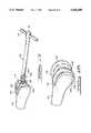
- FIG. 7is a perspective view of an angle guide used for measuring the valgus angle of the femur according to the preferred embodiment of the present invention.
- FIG. 8is a perspective view showing the use of the femoral provisional according to the preferred embodiment of the present invention.
- FIG. 9is a side elevational view of a femur and tibia at 90° of flexion shown with the femoral provisional and spacer block in place according to the preferred embodiment of the present invention.
- FIG. 10is a side elevational view of a femur and tibia in full extension shown with the femoral provisional and spacer block in place according to the preferred embodiment of the present invention
- FIG. 11is a cross-sectional view of a femur showing a screw in the bore of an intramedullary rod in its most proximal position according to the preferred embodiment of the present invention
- FIG. 12is a cross-sectional view of a femur showing a screw in the bore of an intramedullary rod in a position more distal than that shown in FIG. 11, according to the preferred embodiment of the present invention
- FIG. 13is a perspective view of a distal drill guide according to the preferred embodiment of the present invention.
- FIG. 14is a perspective view of a distal resection guide according to the preferred embodiment of the present invention.
- FIG. 15is a perspective view of an anterior-posterior resection guide according to the preferred embodiment of the present invention.
- FIG. 16is a perspective view of a chamfer resection guide according to the preferred embodiment of the present invention.
- FIG. 17is a perspective view of an extractor removing an intramedullary rod from the femur according to the preferred embodiment of the present invention.
- FIG. 18is a perspective view of an appropriately shaped distal femoral surface showing the femoral component of a knee joint prosthesis affixed thereto according to the preferred embodiment of the present invention
- FIG. 19is a perspective view of a threaded angled support member and a femoral provisional having a threaded cylindrical member according to another embodiment of the present invention.
- FIG. 20is a perspective view of a threaded angled support member and a femoral provisional according to yet a further embodiment of the present invention.
- FIG. 1there is shown a knee joint prosthesis 20 having a femoral component 22 and a tibial component 24.
- the femoral component 22 and the tibial component 24are shown as being functionally depicted as being secured to a tibia 26 and femur 27 of a surgically resected right knee joint, with the tibia 26 and femur 27 being shown in phantom.
- any suitable knee joint prosthesismay be utilized in the present invention.
- the present inventionmay be used for both right and left knee joint prosthesis surgery.
- the set of surgical instrumentsis used to provide means for adjustably positioning a plurality of resection guides in response to the provisional placement of the femoral component 22 of the knee joint prosthesis 20.
- the set of surgical instruments 28comprises an intramedullary rod 30 which is used for positioning the various femoral shaping instrumentation discussed below.
- the intramedullary rod 30is straight and comprises a plurality of flutes 32 which are used to prevent rotation of the intramedullary rod 30 when the intramedullary rod 30 is located in the femur 27.
- the intramedullary rod 30also includes a flange portion 34 which is used when impacting the intramedullary rod 30 into the femur 27.
- the intramedullary rod 30also comprises a blind bore 36 as well as a hex portion 38.
- the blind bore 36includes a threaded end portion 40 located at one end thereof which is used to threadably engage a screw described in more detail below.
- the hex portion 38is used for attaching other instrumentation to intramedullary rod 30.
- the length of the intramedullary rod 30is approximately the length of the stem of the prosthesis that will be later utilized during the revision surgery.
- the diameter of the intramedullary rod 30is approximately 9 mm. However, the diameter of the intramedullary rod 30 may be somewhat larger if desired.
- the set of surgical instruments 28further includes a reamer 42.
- the reamer 42is used to form a cavity in the intramedullary canal so that intramedullary rod 30 may be inserted into the intramedullary canal. While the reamer 42 may be rotated by a drill, the reamer 42 may also have a T-shaped handle which allows manual rotation of the reamer. As will be more fully described below, the reamer 42 is initially inserted into a hole formed by a drill and is then rotated to form the cavity.
- an impactor 44is provided.
- the impactor 44is used for driving the intramedullary rod 30 into the intramedullary canal and comprises an elongated member 46 and a vertical alignment rod 48 attached thereto at a right angle.
- the vertical alignment rod 48is used to align intramedullary rod 30 in the intramedullary canal as will be described below.
- the impactor 44comprises a hex portion 50 which corresponds to the hex portion 38 of intramedullary rod 30. The hex portion 50 allows the impactor 44 to engage the intramedullary rod 30 in a relatively secure fashion when the impactor 44 is driving the intramedullary rod 30 into the intramedullary canal.
- the set of surgical instruments 28further includes an extractor 52.
- the extractor 52is used for extracting intramedullary rod 30 from the intramedullary canal after the femur 27 has been resected as described below.
- the extractor 52includes a handle portion 54 which is used for grasping and rotating the extractor 52.
- the extractor 52also comprises a threaded end portion 56 which is operable to engage the threaded portion 40 of the intramedullary rod 30.
- the set of surgical instruments 28further includes a threaded member in the form of a screw 58.
- the screw 58is used for adjusting the effective depth of the blind bore 36 of intramedullary rod 30 so as to establish a locating surface for the support member described below.
- the screw 58comprises a threaded portion 60 which is able to engage the threaded portion 40 of the intramedullary rod 30.
- the screw 58includes a head portion 62 having a hex-shaped bore portion 64. The hex-shaped bore portion 64 of the head portion 62 is used to allow the screw 58 to be inserted and extracted with a hex driver described below.
- the set of surgical instruments 28further includes an angle guide 66 which is best shown in FIG. 7.
- the angle guide 66is used to determine the valgus angle of the femur 27 and includes a rod 68, an extension member 70 and a direction member 72.
- the extension member 70comprises a hex portion 74 which is operable to engage the hex portion 38 of the intramedullary rod 30.
- the extension member 70comprises an angle measuring device 76 which is used for measuring the angle indicated by a pointer member which is located on the direction member 72 as described below.
- the extension member 70also comprises a bore 78 which is used for attaching the direction member 72 to the extension member 70.
- the direction member 72 of the angle guide 66comprises a rotating head 80 having an aperture (not shown) which is used for receiving the rod 68.
- the direction member 72includes an insertion member 82 which is operable to be received by the bore 78 of the extension member 70.
- the directional member 72includes a pointer member 84 which is used to indicate the valgus angle of the femur 27 on the angle measuring device 76 as described below.
- an angled support member 86is also provided.
- the exterior of the angled support member 86is hexed shaped so as to be operable to be inserted into the hex portion 38 of intramedullary rod 30.
- the angled support member 86includes an angled end portion 88 and a flat end portion 90.
- the angled end portion 88is angularly displaced from a plane perpendicular to the axial centerline of the angled support member 86 by the valgus angle determined by the angle guide 66.
- the set of surgical instruments 28includes a plurality of angled support members each having a different valgus angle.
- the angled support member 86comprises a threaded bore 92 (shown in phantom in FIG. 2) at angled end 88 which is used to attach angled support member 86 to other instruments.
- the set of angled support members 86have angles varying from about 5° to about 12°.
- the valgus angle associated with each of the angled support members 86is located at the flat end portion 90 of the angled member.
- angle support member 86includes threads 94 at angled end 88 of angled support member 86. The threads 94 on angle support member 86 may then be threadably engaged with threaded portions of other instrumentation as described below.
- the set of surgical instruments 28further includes a femoral provisional 96.
- the femoral provisional 96is used for determining the proper size of the femoral component 22 as well as the proper alignment of resection instrumentation described below.
- the femoral provisional 96comprises a passage 98 which is used for attaching the femoral provisional 96 to angled support member 86 by means of the attachment screw described below.
- the external contour of the femoral provisional 96is similar to the external surface of the femoral component but thinner so as to provide clearance on bone that may be lost.
- the femoral provisional 96also includes a flange portion 99 used to prevent rotation of the angled support member 86 in a manner described below.
- the set of surgical instruments 28includes several femoral provisionals 96 which are of different sizes. Each of the femoral provisionals 96 has about a 5 mm difference in width and about a 4 mm difference in depth. The set of femoral provisionals ranges in size from about 55 to about 80.
- a threaded membersuch as the attachment screw 100 is provided.
- the attachment screw 100is used to attach the angled hex piece 86 to the femoral provisionals 96 as well as to other instrumentation described below.
- the attachment screw 100includes a threaded portion which is able to engage the threaded bore 92 of the angled support member 86. Accordingly, by inserting the attachment screw 100 through the hole in the femoral provisional and allowing the threads of the attachment screw 100 to engage the threaded bore 92 of the angled support member 86, the femoral provisional may be secured to the angled support member 86.
- the set of surgical instruments 28further includes a spacer block 104.
- the spacer block 104is used for determining the thickness of the tibial component 24 of a knee prosthesis 20 as well as the proper positioning of the various resection guides as more fully described below.
- the spacer block 104comprises a spacer pad 106 which is used for measuring the distance between the tibia 26 and the femoral provisional 96.
- the spacer block 104comprises a handle 108 which is used to move the spacer block 104 from one position to another.
- a distal resection guide 110is provided.
- the distal resection guide 110comprises a plurality of holes 112 and 114 which are used for attaching the distal resection guide 110 to the femur 27.
- the pins 116 and 118are placed in holes 112 and 114 and are used to hold the distal resection guide 110 in the proper position on the femur 27.
- the distal resection guide 110also comprises a cutting guide surface 120 which is used to align the cutting blade in the proper position for distal resection.
- the set of surgical instruments 28further comprises a distal drill guide 122.
- the distal drill guide 122is used for positioning drilled holes in the femur 27 which are used to align the distal resection guide 110.
- the distal drill guide 122comprises a plurality of holes 124 which accept drill bits which are connected to a drill.
- the distal drill guide 122also comprises a stem 126 having an aperture 128. The aperture 128 is used for attaching the distal drill guide 122 to the angled support member 86.
- the set of surgical instruments 28further comprises an anterior-posterior resection guide 130.
- the anterior-posterior resection guide 130includes an aperture 132 which is used for attaching the anterior-posterior resection guide 130 to the angled support member 86.
- the anterior-posterior resection guide 130comprises a cutting guide surface 134 and cutting guide surfaces 136 and 138 which are used to align a cutting blade in the proper position for anterior-posterior resection as will be more fully described below.
- the anterior-posterior resection guide 130may also have slots or other types of surfaces which may be used to facilitate resection.
- the set of surgical instruments 28further includes a chamfer resection guide 140.
- the chamfer resection guide 140is used to guide a cutting blade in making a chamfer resection.
- the chamfer resection guide 140comprises an aperture 142 which is used to attach the chamfer resection guide 140 to the angled support member 86.
- the chamfer resection guide 140comprises a cutting guide surface 144 and a cutting guide surface 146 which are used to align cutting blade 148 in the proper position for chamfer resection.
- the set of surgical instruments 28 described aboveis used to prepare the femur 27 to accept a femoral component of a knee joint prosthesis during revision surgery.
- the followingis a detailed description of the method for using the set of surgical instruments 28 of the present invention. It will be appreciated, however, that the following discussion concerns only one method for using the set of surgical instruments 28. Other methods will be appreciated by those skilled in the art.
- the femur 27is shown after the primary implant (not shown) has been removed. After the primary implant has been removed, a hole 150 is drilled in the distal surface of the intercondylar notch of femur 27. Standard instrumentation such as drill 152 depicted in FIG. 3 may be used.
- a reamer 42is then inserted into the hole 150 created by the drill 152 as shown in FIG. 4.
- the reamer 42is then rotated so as to form a cavity within the intramedullary canal.
- the cavityextends approximately 6 to 8 inches into the intramedullary canal.
- the hex portion 50 of the impactor 44is inserted into the corresponding hex portion 38 of the intramedullary rod 30.
- the orientation of the intramedullary rod 30 in relation to the impactor 44is such that the flat portion 154 of the intramedullary rod 30 is posterior to allow for clearance of the posterior cruciate ligament (when the ligament is retained) as shown in FIG. 5.
- the vertical alignment rod 48should be vertical to the femur 27 to assure proper alignment of the intramedullary rod 30.
- Alternative methods of alignmentinclude using a horizontally oriented alignment rod and employing the epicondyles as landmarks.
- the intramedullary rod 30is then placed into the cavity 156 and driven into the cavity 156 formed by the reamer 42 as shown in FIG. 5.
- a mallet 158may be employed to assist the insertion of intramedullary rod 30.
- the intramedullary rod 30is inserted into the canal until the flutes 32 of intramedullary rod 30 engage the femur 27.
- the flange portion 34 of the intramedullary rod 30should be level with the remaining bone to assure proper positioning. Further manipulations such as additional rods or sleeves may be utilized to assure that the intramedullary rod 30 fits securely in the cavity formed in the intramedullary canal. If the intramedullary rod 30 requires readjustment, extractor 52 may be employed to remove and reinsert the intramedullary rod 30.
- the screw 58is inserted into the blind bore 36 of the intramedullary rod 30 with the hex driver 160 as shown in FIG. 6. As this occurs, the threaded portion 60 of the screw 58 engages the threaded portion 40 of the blind bore 36.
- the screw 58may be moved distally and proximally within the blind bore 36. The position of the screw 58 within the blind bore 36 determines the depth of the blind bore 36.
- FIG. 11shows the screw 58 positioned as far proximally as possible
- FIG. 12shows the screw 58 positioned distally with respect to the position shown in FIG. 11.
- the screw 58should be first positioned proximally as shown in FIG. 11 to allow for maximum adjustability.
- the extension member 70is attached to the intramedullary rod 30 by inserting the hex portion 74 of the angle guide 66 into the hex portion 38 of the intramedullary rod 30.
- the insertion member 82 of the direction member 72is then inserted into the bore 78 of the extension member 70 so that the direction member 72 is vertical to the femur 27 and the pointer 84 is directly above the angle measuring device 76.
- the rod 68is then inserted into an aperture of the rotating head 80 of the direction member 72. As shown in FIG.
- the free end of the rod 68is placed to the center of the femoral head 162 located at the proximal end of the femur 27.
- the center of the femoral head 162may be determined by various methods. Once the rod 68 is placed on the center of the femoral head 162, the pointer 84 will be directed to a number on the angle measuring device 76. This number represents the valgus angle of the femur 27. It will be appreciated that other methods for determining the valgus angle may be employed, such as x-ray evaluation. Once the valgus angle is determined, the angle guide 66 is disassembled and the extension member 70 is removed from intramedullary rod 30.
- the angled support member 86is then selected which has an angled end portion 88 which is angularly displaced by an angle which is closest to the previously determined valgus angle.
- a femoral provisional 96 of the appropriate sizeis also selected.
- a variety of methods for selecting the size of the femoral provisional 96may be utilized such as comparing the femoral provisional 96 to the remaining bone, examining the knee not engaged in surgery and analyzing x-rays taken prior to primary replacement surgery.
- the screw 100is inserted through the passage 98 of the femoral provisional 96 until the end portion 164 of the screw 100 passes through the passage 98 and the head 166 of screw 100 is resting on the femoral provisional 96.
- the threaded blind bore 92 of the selected angled support member 86is threadably engaged with the screw 100 so that the angled support member 86 is securely fastened to the femoral provisional 96. Because two sides of the angled support member 86 engage the flange portion 99 (see FIG. 2), the flange portion 99 prevents rotation of the angled support member 86.
- the angled support member 86is connected to the femoral provisional 96 in one of two orientations in order for it to properly function depending on whether a right or left knee is involved. That is, by rotating the angled support member 86 by 180°, the angled support member 86 may accommodate either a left knee or a right knee.
- the kneeis then placed in 90° of flexion and the spacer blocks 104 of different thicknesses are inserted between the femoral provisional 96 and the flat surface of the tibia 26. This is shown in FIG. 9.
- the surgeondetermines which spacer block 104 provides a tight fit against the forces of the soft tissues. As shown in FIG. 10, the same procedure is used when the knee is in full extension. Again, a determination is made as to which spacer block 104 provides a tight fit against the soft tissues. If the same thickness spacer block 104 provides the best fit in both flexion and extension, the correct placement of the femoral component of the prosthesis is that of the femoral provisional 96 and the correct thickness of the tibial component is that of the spacer block 104. If the thickness of the spacer block 104 in flexion and extension is not the same, further manipulations as described below must be made so that the same thickness of the spacer block 104 is used in both flexion and extension.
- the femoral provisional 96is moved distally. Accordingly, the angled support member 86 and the femoral provisional 96 are removed from the intramedullary rod 30.
- the screw 58 within the blind bore 36is adjusted with the hex driver 160 so that it is more distally located. Optimally, the screw 58 is moved the same distance as the difference in the thickness between the spacer block 104 in flexion and the spacer block 104 in extension.
- the screw 58should be moved distally 8 mm so the femoral provisional 96 is also moved distally 8 mm.
- the distance which the screw 58 is movedmay be calculated by determining the distance between the threads on the threaded portion 60 and the number of turns made with the hex driver 160.
- Alternative means for determining the distance the screw 58 is movedmay also be employed such as inserting a measuring device into the blind bore 36 until it rests on the head 62 of the screw 58 before the screw 58 has been moved, and then again after the screw 58 has been moved.
- the angled support member 86 with the femoral provisional 96 attachedis again inserted into the blind bore 36 of the intramedullary rod 30 until the angled support member 86 contacts the head 62 of the screw 58.
- the spacer blocks 104 of various thicknessesare again inserted between the femoral provisional 96 and the flat surface of the tibia 26 to determine which thickness of spacer block 104 provides a tight fit against the forces of the soft tissue during both flexion and extension. If the thickness of the spacer block 104 is the same in both flexion and extension, the femoral provisional 96 is of the appropriate size and is in the proper position. In addition, the thickness of the bearing member of the tibial component 24 will be the same thickness as the spacer block 104.
- a larger femoral provisional 96is used.
- the larger femoral provisional 96is attached to the angled support member 86 and the intramedullary rod 30 as previously described.
- the thickness of the spacer block 104 in flexion and extensionis again determined. If the thickness of the spacer block 104 is not the same in flexion and extension, the femoral provisional 96 is replaced with a different size femoral provisional 96 or the screw 58 may be moved distally or proximally within bore 36. If these manipulations do not provide for the spacer block 104 having the same thickness in both flexion and extension, the intramedullary rod 30 may be impacted further into the femur 27.
- the angled support member 86is removed from the femoral provisional 96 while the screw 58 is left in the same position in the blind bore 36. This position will be used to properly align the various femoral shaping instruments on the distal femoral surface prior to resection as described below.
- the angled end portion 88 of the angled support member 86is attached to the distal drill guide 122 and the flat end 90 of angled support member 86 is inserted into the blind bore 36 of the intramedullary rod 30 until the angled support member 86 bottoms out against the head 62 of the screw 58 as shown in FIG. 13.
- Two holesare then drilled in the femur 27 based on the holes 124 of the distal drill guide 122.
- the angled support member 86 and the distal drill guide 122are then removed and the angled support member 86 is then removed from the distal drill guide 122.
- the distal resection guide 110is attached to the femur 27 by placing the pin 116 and the pin 118 in the holes 112 and 114 of the distal resection guide 110 and in the holes in the femur 27 formed by the distal drill guide 122. A distal resection is then made by a cutting blade 148 based on the placement of the distal resection guide 110. The distal resection guide 110 is then removed from the femur 27.
- the angled end portion 88 of the angled support member 86is then placed in the aperture 132 of anterior-posterior femoral resection guide 130 and the screw 100 is threadably engaged in the blind bore 92 of the angled support member 86 to attach the angled support member 86 to the anterior-posterior resection guide 130.
- the flat end 90 of the angled support member 86is then inserted into the hex portion 38 of the intramedullary rod 30 until it contacts the head 62 of the screw 58.
- anterior and posterior resectionsare then made by a cutting blade 148 which uses the anterior-posterior resection guide 130 to guide the cutting blade 148.
- the angled support member 86 and the anterior-posterior resection guide 130are removed.
- the angled support member 86is removed from the anterior-posterior resection guide 130.
- the angled end portion 88 of the angled support member 86is then placed in the aperture 142 of the chamfer resection guide 140 and the screw 100 is threadably engaged in the blind bore 92 of the angled support member 86 to attach the angled support member 86 to the chamfer resection guide 140.
- the flat end 90 of the angled support member 86is then inserted into the hex 38 of the intramedullary rod 30 until it contacts on the head 62 of the screw 58.
- the chamfer resectionsare then made by a cutting blade 148 using the chamfer resection guide 140 to guide the cutting blade 148.
- the angled support member 86 attached to the chamfer resection guide 140is then removed from the intramedullary rod 30 and the angled support member 86 is removed from the chamfer resection guide 140.
- the intramedullary rod 30is then removed from the intramedullary canal using the extractor 52 as shown in FIG. 17.
- the screw 58is first removed from the intramedullary rod 30.
- the extractor 52is then inserted into the blind bone 36 of the intramedullary rod 30 so that the threaded portion 56 of the extractor 52 engages the threaded portion 40 of the intramedullary rod 30. Force is exerted in the direction of the arrow in FIG. 17 by grasping and pulling on the handle 54 of the extractor 52.
- FIG. 18shows the resulting shaped distal femoral surface of the femur 27 with resected anterior surfaces 170 and 172 and resected posterior surfaces 174 and 176, situated about the distal femoral surface 178.
- the shaped distal femoral surfaceis fitted with a femoral component 22 of a knee joint prosthesis 20 of the type well-known in the art having an interior surface selected to properly fit over the shaped distal femoral surface. It will be appreciated that other bone may have to be removed prior to fixing a femoral component 22 of a knee prosthesis 20.
- the threads 94 of the angled support member 86may be threadably engaged with the threaded cylindrical member 102 of the femoral provisional 96 so that angled support member 86 is securely fastened to the femoral provisional 96.
- the flat end 90 of the angled support member 86is then inserted into the intramedullary rod 30 until the femoral provisional 96 bottoms out against the head 62 of screw 58.
- the femoral provisional 96is positioned on the distal end of the femur 27 based on the previously determined valgus angle of femur 27.
- the set of surgical instruments 28includes an angled support member 180 having an internal threaded member in the form of a screw 182.
- the screw 182is able to threadably engage a threaded portion 184 of the blind bore 36 so as to secure the angled support member 180 to the blind bore 36. Because the support member 180 includes a central bore 186, the screw 182 may be rotated while the support member 180 is attached to the intramedullary rod 30 to adjust the positions of the femoral provisional 96.
- the angled support member 180may be also secured to the anterior/posterior resection guide 132, the chamfer resection guide 140 as well as the drill guide 122 during resection in a manner similar to that described below.
- the impactor and the extractormay be combined so that both insertion and extraction are performed with the same instrument.
- a calibrated distractormay be used to balance the soft tissues especially in extension.
- the support membermay have different cross-sections other than hexagonal (e.g., D-shaped, rectangular, oval, etc.)
- the spacer blocksmay be used throughout different ranges of flexion.
- the set of surgical instrumentsmay be used in conjunction with various methods for sensing pressure prior to implantation of a prosthetic knee joint such as that disclosed in U.S. Ser. No. 07/790,176.
- Various other alternatives and modificationsmay be made to the illustrative embodiment without departing from the spirit and scope of the invention.
Landscapes
- Health & Medical Sciences (AREA)
- Orthopedic Medicine & Surgery (AREA)
- Life Sciences & Earth Sciences (AREA)
- Transplantation (AREA)
- Engineering & Computer Science (AREA)
- Public Health (AREA)
- Biomedical Technology (AREA)
- Heart & Thoracic Surgery (AREA)
- Surgery (AREA)
- Veterinary Medicine (AREA)
- Animal Behavior & Ethology (AREA)
- General Health & Medical Sciences (AREA)
- Oral & Maxillofacial Surgery (AREA)
- Physical Education & Sports Medicine (AREA)
- Molecular Biology (AREA)
- Nuclear Medicine, Radiotherapy & Molecular Imaging (AREA)
- Medical Informatics (AREA)
- Cardiology (AREA)
- Vascular Medicine (AREA)
- Dentistry (AREA)
- Surgical Instruments (AREA)
Abstract
Description
Claims (19)
Priority Applications (1)
| Application Number | Priority Date | Filing Date | Title |
|---|---|---|---|
| US07/988,229US5464406A (en) | 1992-12-09 | 1992-12-09 | Instrumentation for revision surgery |
Applications Claiming Priority (1)
| Application Number | Priority Date | Filing Date | Title |
|---|---|---|---|
| US07/988,229US5464406A (en) | 1992-12-09 | 1992-12-09 | Instrumentation for revision surgery |
Publications (1)
| Publication Number | Publication Date |
|---|---|
| US5464406Atrue US5464406A (en) | 1995-11-07 |
Family
ID=25533947
Family Applications (1)
| Application Number | Title | Priority Date | Filing Date |
|---|---|---|---|
| US07/988,229Expired - LifetimeUS5464406A (en) | 1992-12-09 | 1992-12-09 | Instrumentation for revision surgery |
Country Status (1)
| Country | Link |
|---|---|
| US (1) | US5464406A (en) |
Cited By (58)
| Publication number | Priority date | Publication date | Assignee | Title |
|---|---|---|---|---|
| US5607431A (en)* | 1995-02-09 | 1997-03-04 | Howmedica Inc. | Prosthetic hip implantation method and apparatus |
| FR2742037A1 (en)* | 1995-12-07 | 1997-06-13 | Broutard Jean Claude | Bone cut preparation instrument, esp. for fitting knee prosthesis |
| US5649929A (en)* | 1995-07-10 | 1997-07-22 | Callaway; George Hadley | Knee joint flexion-gap distraction device |
| US5735904A (en)* | 1995-07-05 | 1998-04-07 | Pappas; Michael J. | Spacer for establishng prosthetic gap and ligamentous tension |
| FR2755602A1 (en)* | 1996-11-12 | 1998-05-15 | Osbone Sc | Surgical instrument for positioning of total knee prosthesis |
| WO1998046152A1 (en)* | 1997-04-14 | 1998-10-22 | Case Medical, Inc. | Long bone reamer |
| US5830216A (en)* | 1996-10-30 | 1998-11-03 | Bristol-Myers Squibb Company | Apparatus and method for knee implantation |
| US5897559A (en)* | 1995-11-02 | 1999-04-27 | Medidea, Llc | Bone cutting guides for use in the implantation of prosthetic joint components |
| FR2770393A1 (en)* | 1997-10-31 | 1999-05-07 | Protek Sa | FEMORAL CUTTING DEVICE FOR PLACING A TOTAL RECOVERY KNEE PROSTHESIS |
| WO2000012017A1 (en)* | 1998-09-01 | 2000-03-09 | Sulzer Orthopedics Inc. | Intramedullary reference datum instrument for bone resection |
| US6168599B1 (en)* | 1997-04-14 | 2001-01-02 | Allan S. Frieze | Long bone reamer |
| WO2000065981A3 (en)* | 1999-04-30 | 2001-02-01 | Niloy Bhadra | Surgical tools |
| US6193723B1 (en) | 1994-12-16 | 2001-02-27 | Exactech, Inc. | Intramedullary alignment guide tool |
| US6228091B1 (en)* | 1998-10-13 | 2001-05-08 | Stryker Technologies Corporation | Methods and tools for tibial intermedullary revision surgery and associated tibial components |
| ES2166258A1 (en)* | 1999-05-11 | 2002-04-01 | Flores Jesus Burgos | Procedure and apparatus used for surgical treatment by endoscopy prior to disorders of the spine, especially scoliosis |
| WO2002028299A1 (en)* | 2000-10-05 | 2002-04-11 | Jesus Burgos Flores | Method and apparatus for surgical treatment of diseases of the vertebral column, especially scoliosis, using anterior endoscopic technique |
| US6371991B1 (en) | 1996-12-23 | 2002-04-16 | Depuy Orthopaedics, Inc. | Alignment guide for fluted prosthetic stems |
| WO2002002021A3 (en)* | 2000-06-29 | 2002-07-18 | Richard V Williamson | Instruments and methods for use in performing knee surgery |
| US20030036764A1 (en)* | 1999-10-13 | 2003-02-20 | Hamada James S. | Spinal fusion instrumentation, implant and method |
| US20030093079A1 (en)* | 1997-09-18 | 2003-05-15 | Masini Michael A. | Joint replacement methods and apparatus |
| US20030120273A1 (en)* | 2001-12-21 | 2003-06-26 | Cole J. Dean | Surgical distractor frame |
| US20040078042A1 (en)* | 1997-09-18 | 2004-04-22 | Masini Michael A. | Bone-conserving orthopedic instrumentation and appliances |
| US6764492B2 (en) | 2001-09-10 | 2004-07-20 | Zimmer Technology, Inc. | Bone impaction instrument |
| US20040153162A1 (en)* | 2003-02-04 | 2004-08-05 | Sanford Adam H. | Provisional orthopedic prosthesis for partially resected bone |
| US20050049603A1 (en)* | 2002-07-23 | 2005-03-03 | Ortho Development Corporation | Knee balancing block |
| US20050143744A1 (en)* | 2003-12-30 | 2005-06-30 | Keeven Richard D. | Augments for surgical instruments |
| US20050177170A1 (en)* | 2004-02-06 | 2005-08-11 | Synvasive Technology, Inc. | Dynamic knee balancer with pressure sensing |
| WO2005099636A1 (en)* | 2004-03-31 | 2005-10-27 | Niigata Tlo Corporation | Intramedullary rod for assisting artificial knee joint replacing operation and method for managing operation using that rod |
| US20050283249A1 (en)* | 2004-06-22 | 2005-12-22 | Carson Christopher P | Systems and processes for determining proper superior-inferior joint line positioning |
| US20060004373A1 (en)* | 2004-06-30 | 2006-01-05 | Ondrla Jeffrey M | Adjustable humeral cutting guide |
| US20060106393A1 (en)* | 2004-11-12 | 2006-05-18 | Huebner Randall J | Bone reamer |
| US20060229543A1 (en)* | 2005-03-13 | 2006-10-12 | Calvo Ignacio J | Wrench for reducing femur midshaft fractures |
| JP2007520317A (en)* | 2004-02-06 | 2007-07-26 | シンバシブ テクノロジー インコーポレイティッド | Dynamic knee balancer |
| US20070233266A1 (en)* | 2006-03-20 | 2007-10-04 | Howmedica Osteonics Corp. | Composite joint implant |
| EP1814471A4 (en)* | 2004-10-25 | 2008-02-06 | Synvasive Technology Inc | Dynamic knee balancer with pressure sensing |
| US7510557B1 (en) | 2000-01-14 | 2009-03-31 | Bonutti Research Inc. | Cutting guide |
| US20100331991A1 (en)* | 2009-05-29 | 2010-12-30 | Zachary Christopher Wilkinson | Methods and Apparatus for Performing Knee Arthroplasty |
| US7959635B1 (en) | 2000-01-14 | 2011-06-14 | Marctec, Llc. | Limited incision total joint replacement methods |
| US20130103160A1 (en)* | 2010-04-22 | 2013-04-25 | Depuy (Ireland) | Composite trial prosthesis |
| US8623030B2 (en) | 2001-08-28 | 2014-01-07 | Bonutti Skeletal Innovations Llc | Robotic arthroplasty system including navigation |
| US8758355B2 (en) | 2004-02-06 | 2014-06-24 | Synvasive Technology, Inc. | Dynamic knee balancer with pressure sensing |
| US8968412B2 (en) | 2011-06-30 | 2015-03-03 | Depuy (Ireland) | Trialing system for a knee prosthesis and method of use |
| DE102014009774A1 (en)* | 2014-07-02 | 2016-01-07 | Ehrhardt Weiß | Orthopedic trauma implant |
| JP2016067719A (en)* | 2014-09-30 | 2016-05-09 | 京セラメディカル株式会社 | Instrument for artificial knee joint replacement surgery and instrument unit for artificial knee joint replacement surgery |
| US9427336B2 (en) | 2013-08-23 | 2016-08-30 | Stryker Corporation | Intraoperative dynamic trialing |
| US9861491B2 (en) | 2014-04-30 | 2018-01-09 | Depuy Ireland Unlimited Company | Tibial trial system for a knee prosthesis |
| US10034690B2 (en) | 2014-12-09 | 2018-07-31 | John A. Heflin | Spine alignment system |
| US10195056B2 (en) | 2015-10-19 | 2019-02-05 | Depuy Ireland Unlimited Company | Method for preparing a patient's tibia to receive an implant |
| EP3456296A1 (en)* | 2017-09-14 | 2019-03-20 | DePuy Ireland Unlimited Company | Orthopaedic surgical instrument extraction system and method |
| JP2019051312A (en)* | 2017-09-14 | 2019-04-04 | デピュイ・アイルランド・アンリミテッド・カンパニーDepuy Ireland Unlimited Company | Orthopedic instrument system and method for removing a trial structure assembly |
| WO2020001830A1 (en)* | 2018-06-26 | 2020-01-02 | Depuy Ireland Unlimited Company | Surgical kit and method |
| US10537445B2 (en) | 2015-10-19 | 2020-01-21 | Depuy Ireland Unlimited Company | Surgical instruments for preparing a patient's tibia to receive an implant |
| EP3666229A1 (en)* | 2018-12-10 | 2020-06-17 | Waldemar Link GmbH & Co. KG | Knee joint endoprosthetic set and instruments |
| US11357644B2 (en) | 2011-10-24 | 2022-06-14 | Synvasive Technology, Inc. | Knee balancing devices, systems and methods |
| US11490899B2 (en) | 2018-06-26 | 2022-11-08 | Depuy Ireland Unlimited Company | Surgical device and method |
| US11490901B2 (en) | 2018-06-26 | 2022-11-08 | Depuy Ireland Unlimited Company | Femoral neck resection guide |
| US11648126B1 (en)* | 2017-02-07 | 2023-05-16 | Jonathan R. Javors | Method and system for femoral condylar resection arthroplasty of the knee |
| US11992226B2 (en) | 2018-06-26 | 2024-05-28 | Depuy Ireland Unlimited Company | Femoral neck resection jig |
Citations (9)
| Publication number | Priority date | Publication date | Assignee | Title |
|---|---|---|---|---|
| US4567885A (en)* | 1981-11-03 | 1986-02-04 | Androphy Gary W | Triplanar knee resection system |
| US4703751A (en)* | 1986-03-27 | 1987-11-03 | Pohl Kenneth P | Method and apparatus for resecting a distal femoral surface |
| US4875475A (en)* | 1984-11-30 | 1989-10-24 | Synthes (U.S.A.) | Device for treating a bone |
| US4935023A (en)* | 1989-01-09 | 1990-06-19 | Dow Corning Wright | Femoral surface shaping guide for knee implants |
| US4938762A (en)* | 1987-12-16 | 1990-07-03 | Protek Ag | Reference system for implantation of condylar total knee prostheses |
| US4952213A (en)* | 1989-02-03 | 1990-08-28 | Boehringer Mannheim Corporation | Tibial cutting guide |
| US5037423A (en)* | 1983-10-26 | 1991-08-06 | Pfizer Hospital Products Group, Inc. | Method and instrumentation for the replacement of a knee prosthesis |
| US5108396A (en)* | 1990-06-07 | 1992-04-28 | Smith & Nephew Richards Inc. | Intramedullary referenced humeral head resection guide |
| US5228459A (en)* | 1990-01-08 | 1993-07-20 | Caspari Richard B | Method of resecting bone |
- 1992
- 1992-12-09USUS07/988,229patent/US5464406A/ennot_activeExpired - Lifetime
Patent Citations (9)
| Publication number | Priority date | Publication date | Assignee | Title |
|---|---|---|---|---|
| US4567885A (en)* | 1981-11-03 | 1986-02-04 | Androphy Gary W | Triplanar knee resection system |
| US5037423A (en)* | 1983-10-26 | 1991-08-06 | Pfizer Hospital Products Group, Inc. | Method and instrumentation for the replacement of a knee prosthesis |
| US4875475A (en)* | 1984-11-30 | 1989-10-24 | Synthes (U.S.A.) | Device for treating a bone |
| US4703751A (en)* | 1986-03-27 | 1987-11-03 | Pohl Kenneth P | Method and apparatus for resecting a distal femoral surface |
| US4938762A (en)* | 1987-12-16 | 1990-07-03 | Protek Ag | Reference system for implantation of condylar total knee prostheses |
| US4935023A (en)* | 1989-01-09 | 1990-06-19 | Dow Corning Wright | Femoral surface shaping guide for knee implants |
| US4952213A (en)* | 1989-02-03 | 1990-08-28 | Boehringer Mannheim Corporation | Tibial cutting guide |
| US5228459A (en)* | 1990-01-08 | 1993-07-20 | Caspari Richard B | Method of resecting bone |
| US5108396A (en)* | 1990-06-07 | 1992-04-28 | Smith & Nephew Richards Inc. | Intramedullary referenced humeral head resection guide |
Non-Patent Citations (2)
| Title |
|---|
| "The Continuum Knee System Surgical Technique", Techmedica Sales Brohcure, 1990. |
| The Continuum Knee System Surgical Technique , Techmedica Sales Brohcure, 1990.* |
Cited By (150)
| Publication number | Priority date | Publication date | Assignee | Title |
|---|---|---|---|---|
| US6193723B1 (en) | 1994-12-16 | 2001-02-27 | Exactech, Inc. | Intramedullary alignment guide tool |
| US5607431A (en)* | 1995-02-09 | 1997-03-04 | Howmedica Inc. | Prosthetic hip implantation method and apparatus |
| US5735904A (en)* | 1995-07-05 | 1998-04-07 | Pappas; Michael J. | Spacer for establishng prosthetic gap and ligamentous tension |
| US5649929A (en)* | 1995-07-10 | 1997-07-22 | Callaway; George Hadley | Knee joint flexion-gap distraction device |
| US6214011B1 (en) | 1995-11-02 | 2001-04-10 | Medidea, Llc | Implantation of prosthetic components based upon joint reduction |
| US5897559A (en)* | 1995-11-02 | 1999-04-27 | Medidea, Llc | Bone cutting guides for use in the implantation of prosthetic joint components |
| US6187010B1 (en) | 1995-11-02 | 2001-02-13 | Medidea, Llc | Bone cutting guides for use in the implantation of prosthetic joint components |
| US5957926A (en)* | 1995-11-02 | 1999-09-28 | Medidea, Llc | Combination trial and bone cutting guides for use in establishing the position of a prosthetic joint component |
| US5961523A (en)* | 1995-11-02 | 1999-10-05 | Medidea, Llc | Bone cutting guides to accommodate variable thicknesses of augmentation for use in the implantation of prosthetic joint components |
| US6602259B1 (en) | 1995-11-02 | 2003-08-05 | Medidea, Llc | Bone cutting guides for use in the implantation of prosthetic joint components |
| FR2742037A1 (en)* | 1995-12-07 | 1997-06-13 | Broutard Jean Claude | Bone cut preparation instrument, esp. for fitting knee prosthesis |
| US5830216A (en)* | 1996-10-30 | 1998-11-03 | Bristol-Myers Squibb Company | Apparatus and method for knee implantation |
| FR2755602A1 (en)* | 1996-11-12 | 1998-05-15 | Osbone Sc | Surgical instrument for positioning of total knee prosthesis |
| US6371991B1 (en) | 1996-12-23 | 2002-04-16 | Depuy Orthopaedics, Inc. | Alignment guide for fluted prosthetic stems |
| WO1998046152A1 (en)* | 1997-04-14 | 1998-10-22 | Case Medical, Inc. | Long bone reamer |
| US6168599B1 (en)* | 1997-04-14 | 2001-01-02 | Allan S. Frieze | Long bone reamer |
| US7419491B2 (en) | 1997-09-18 | 2008-09-02 | Medidea, Llc | Bone-conserving orthopedic instrumentation and appliances |
| US20040078042A1 (en)* | 1997-09-18 | 2004-04-22 | Masini Michael A. | Bone-conserving orthopedic instrumentation and appliances |
| US20040078043A1 (en)* | 1997-09-18 | 2004-04-22 | Masini Michael A. | Joint replacement methods and apparatus |
| US20030093079A1 (en)* | 1997-09-18 | 2003-05-15 | Masini Michael A. | Joint replacement methods and apparatus |
| US20060195113A1 (en)* | 1997-09-18 | 2006-08-31 | Masini Michael A | Joint replacement methods and apparatus |
| US7128745B2 (en) | 1997-09-18 | 2006-10-31 | Medidea, Llc | Joint replacement methods and apparatus |
| FR2770393A1 (en)* | 1997-10-31 | 1999-05-07 | Protek Sa | FEMORAL CUTTING DEVICE FOR PLACING A TOTAL RECOVERY KNEE PROSTHESIS |
| EP0914806A1 (en)* | 1997-10-31 | 1999-05-12 | Protek Synthes S.A. | Femur cutting apparatus for the replacement of a knee joint prothesis |
| US6120509A (en)* | 1998-09-01 | 2000-09-19 | Sulzer Orthopedics Inc. | Intramedullary reference datum instrument |
| WO2000012017A1 (en)* | 1998-09-01 | 2000-03-09 | Sulzer Orthopedics Inc. | Intramedullary reference datum instrument for bone resection |
| US6228091B1 (en)* | 1998-10-13 | 2001-05-08 | Stryker Technologies Corporation | Methods and tools for tibial intermedullary revision surgery and associated tibial components |
| WO2000065981A3 (en)* | 1999-04-30 | 2001-02-01 | Niloy Bhadra | Surgical tools |
| ES2166258A1 (en)* | 1999-05-11 | 2002-04-01 | Flores Jesus Burgos | Procedure and apparatus used for surgical treatment by endoscopy prior to disorders of the spine, especially scoliosis |
| ES2166258B1 (en)* | 1999-05-11 | 2004-11-16 | Jesus Burgos Flores | PROCEDURE AND APPLIANCES USED FOR SURGICAL TREATMENT BY PREVIOUS ENDOSCOPIC TECHNIQUE OF DISEASES OF THE VERTEBRAL COLUMN, ESPECIALLY SCHOLIOSIS. |
| US7351244B2 (en) | 1999-10-13 | 2008-04-01 | Hamada James S | Spinal fusion instrumentation, implant and method |
| US20030036764A1 (en)* | 1999-10-13 | 2003-02-20 | Hamada James S. | Spinal fusion instrumentation, implant and method |
| US7806897B1 (en) | 2000-01-14 | 2010-10-05 | Marctec, Llc | Knee arthroplasty and preservation of the quadriceps mechanism |
| US7892236B1 (en) | 2000-01-14 | 2011-02-22 | Marctec, Llc | System and method for total joint replacement |
| US7931690B1 (en) | 2000-01-14 | 2011-04-26 | Marctec, Llc | Method of resurfacing an articular surface of a bone |
| US7837736B2 (en) | 2000-01-14 | 2010-11-23 | Marctec, Llc | Minimally invasive surgical systems and methods |
| US7708740B1 (en) | 2000-01-14 | 2010-05-04 | Marctec, Llc | Method for total knee arthroplasty and resecting bone in situ |
| US7635390B1 (en) | 2000-01-14 | 2009-12-22 | Marctec, Llc | Joint replacement component having a modular articulating surface |
| US7959635B1 (en) | 2000-01-14 | 2011-06-14 | Marctec, Llc. | Limited incision total joint replacement methods |
| US7615054B1 (en) | 2000-01-14 | 2009-11-10 | Martec, LLC | Bicompartmental knee implant and method |
| US8133229B1 (en) | 2000-01-14 | 2012-03-13 | Marctec, Llc. | Knee arthroplasty method |
| US7510557B1 (en) | 2000-01-14 | 2009-03-31 | Bonutti Research Inc. | Cutting guide |
| US9795394B2 (en) | 2000-01-14 | 2017-10-24 | Bonutti Skeletal Innovations Llc | Method for placing implant using robotic system |
| US8425522B2 (en) | 2000-01-14 | 2013-04-23 | Bonutti Skeletal Innovations Llc | Joint replacement method |
| US9192459B2 (en) | 2000-01-14 | 2015-11-24 | Bonutti Skeletal Innovations Llc | Method of performing total knee arthroplasty |
| US9101443B2 (en) | 2000-01-14 | 2015-08-11 | Bonutti Skeletal Innovations Llc | Methods for robotic arthroplasty |
| US7749229B1 (en) | 2000-01-14 | 2010-07-06 | Marctec, Llc | Total knee arthroplasty through shortened incision |
| US7806896B1 (en) | 2000-01-14 | 2010-10-05 | Marctec, Llc | Knee arthroplasty method |
| US8784495B2 (en) | 2000-01-14 | 2014-07-22 | Bonutti Skeletal Innovations Llc | Segmental knee arthroplasty |
| US8632552B2 (en) | 2000-01-14 | 2014-01-21 | Bonutti Skeletal Innovations Llc | Method of preparing a femur and tibia in knee arthroplasty |
| US7828852B2 (en) | 2000-01-14 | 2010-11-09 | Marctec, Llc. | Inlaid articular implant |
| US20050085920A1 (en)* | 2000-06-29 | 2005-04-21 | Williamson Richard V. | Instruments and methods for use in performing knee surgery |
| US6942700B2 (en) | 2000-06-29 | 2005-09-13 | Richard V. Williamson | Instruments and methods for use in performing knee surgery |
| US7273500B2 (en) | 2000-06-29 | 2007-09-25 | Williamson Richard V | Instruments and methods for use in performing knee surgery |
| WO2002002021A3 (en)* | 2000-06-29 | 2002-07-18 | Richard V Williamson | Instruments and methods for use in performing knee surgery |
| US20020133164A1 (en)* | 2000-06-29 | 2002-09-19 | Williamson Richard V. | Instruments and methods for use in performing knee surgery |
| WO2002028299A1 (en)* | 2000-10-05 | 2002-04-11 | Jesus Burgos Flores | Method and apparatus for surgical treatment of diseases of the vertebral column, especially scoliosis, using anterior endoscopic technique |
| US10231739B1 (en) | 2001-08-28 | 2019-03-19 | Bonutti Skeletal Innovations Llc | System and method for robotic surgery |
| US9060797B2 (en) | 2001-08-28 | 2015-06-23 | Bonutti Skeletal Innovations Llc | Method of preparing a femur and tibia in knee arthroplasty |
| US9763683B2 (en) | 2001-08-28 | 2017-09-19 | Bonutti Skeletal Innovations Llc | Method for performing surgical procedures using optical cutting guides |
| US8858557B2 (en) | 2001-08-28 | 2014-10-14 | Bonutti Skeletal Innovations Llc | Method of preparing a femur and tibia in knee arthroplasty |
| US8834490B2 (en) | 2001-08-28 | 2014-09-16 | Bonutti Skeletal Innovations Llc | Method for robotic arthroplasty using navigation |
| US10321918B2 (en) | 2001-08-28 | 2019-06-18 | Bonutti Skeletal Innovations Llc | Methods for robotic surgery using a cannula |
| US10470780B2 (en) | 2001-08-28 | 2019-11-12 | Bonutti Skeletal Innovations Llc | Systems and methods for ligament balancing in robotic surgery |
| US8641726B2 (en) | 2001-08-28 | 2014-02-04 | Bonutti Skeletal Innovations Llc | Method for robotic arthroplasty using navigation |
| US8840629B2 (en) | 2001-08-28 | 2014-09-23 | Bonutti Skeletal Innovations Llc | Robotic arthroplasty system including navigation |
| US8623030B2 (en) | 2001-08-28 | 2014-01-07 | Bonutti Skeletal Innovations Llc | Robotic arthroplasty system including navigation |
| US6764492B2 (en) | 2001-09-10 | 2004-07-20 | Zimmer Technology, Inc. | Bone impaction instrument |
| US20030120273A1 (en)* | 2001-12-21 | 2003-06-26 | Cole J. Dean | Surgical distractor frame |
| US7311711B2 (en) | 2001-12-21 | 2007-12-25 | Cole J Dean | Surgical distractor frame |
| US20050049603A1 (en)* | 2002-07-23 | 2005-03-03 | Ortho Development Corporation | Knee balancing block |
| US7628793B2 (en) | 2002-07-23 | 2009-12-08 | Ortho Development Corporation | Knee balancing block |
| US20040153162A1 (en)* | 2003-02-04 | 2004-08-05 | Sanford Adam H. | Provisional orthopedic prosthesis for partially resected bone |
| US6916324B2 (en)* | 2003-02-04 | 2005-07-12 | Zimmer Technology, Inc. | Provisional orthopedic prosthesis for partially resected bone |
| US20050143744A1 (en)* | 2003-12-30 | 2005-06-30 | Keeven Richard D. | Augments for surgical instruments |
| JP2005193048A (en)* | 2003-12-30 | 2005-07-21 | Depuy Products Inc | Surgical instrument aids |
| US8025663B2 (en)* | 2003-12-30 | 2011-09-27 | Depuy Products, Inc. | Augments for surgical instruments |
| AU2004242486B2 (en)* | 2003-12-30 | 2010-04-29 | Depuy Products, Inc. | Augments for surgical instruments |
| US7442196B2 (en) | 2004-02-06 | 2008-10-28 | Synvasive Technology, Inc. | Dynamic knee balancer |
| JP2007520317A (en)* | 2004-02-06 | 2007-07-26 | シンバシブ テクノロジー インコーポレイティッド | Dynamic knee balancer |
| US8758355B2 (en) | 2004-02-06 | 2014-06-24 | Synvasive Technology, Inc. | Dynamic knee balancer with pressure sensing |
| US20050177169A1 (en)* | 2004-02-06 | 2005-08-11 | Synvasive Technology, Inc. | Dynamic knee balancer |
| US20090287310A1 (en)* | 2004-02-06 | 2009-11-19 | Synvasive Technology, Inc. | Dynamic knee balancer with pressure sensing |
| US10555822B2 (en) | 2004-02-06 | 2020-02-11 | Synvasive Technology, Inc. | Dynamic knee balancer with force or pressure sensing |
| US8715290B2 (en) | 2004-02-06 | 2014-05-06 | Synvasive Technology, Inc. | Dynamic knee balancer with pressure sensing |
| US7578821B2 (en)* | 2004-02-06 | 2009-08-25 | Synvasive Technology, Inc. | Dynamic knee balancer with pressure sensing |
| US20050267485A1 (en)* | 2004-02-06 | 2005-12-01 | Synvasive Technology, Inc. | Dynamic knee balancer with opposing adjustment mechanism |
| US20050177170A1 (en)* | 2004-02-06 | 2005-08-11 | Synvasive Technology, Inc. | Dynamic knee balancer with pressure sensing |
| US8491589B2 (en) | 2004-02-06 | 2013-07-23 | Synvasive Technology, Inc. | Dynamic knee balancer with pressure sensing |
| US9572588B2 (en) | 2004-02-06 | 2017-02-21 | Synvasive Technology, Inc. | Dynamic knee balancer with force or pressure sensing |
| US7837691B2 (en) | 2004-02-06 | 2010-11-23 | Synvasive Technology, Inc. | Dynamic knee balancer with opposing adjustment mechanism |
| WO2006047005A2 (en) | 2004-02-06 | 2006-05-04 | Synvasive Technology, Inc. | Dynamic knee balancer with pressure sensing |
| US20110071537A1 (en)* | 2004-03-31 | 2011-03-24 | Yoshio Koga | Intramedullary Rod for Assisting Total Knee Joint Replacing Operation and Method for Controle Operation Using the Rod |
| WO2005099636A1 (en)* | 2004-03-31 | 2005-10-27 | Niigata Tlo Corporation | Intramedullary rod for assisting artificial knee joint replacing operation and method for managing operation using that rod |
| US20050283249A1 (en)* | 2004-06-22 | 2005-12-22 | Carson Christopher P | Systems and processes for determining proper superior-inferior joint line positioning |
| US7662156B2 (en)* | 2004-06-22 | 2010-02-16 | Smith & Nephew, Inc. | Systems and processes for determining proper superior-inferior joint line positioning |
| US7198628B2 (en)* | 2004-06-30 | 2007-04-03 | Depuy Products, Inc. | Adjustable humeral cutting guide |
| US20060004373A1 (en)* | 2004-06-30 | 2006-01-05 | Ondrla Jeffrey M | Adjustable humeral cutting guide |
| JP2008517708A (en)* | 2004-10-25 | 2008-05-29 | シンバシブ テクノロジー インコーポレイティッド | Dynamic knee balancer with pressure sensitive part |
| EP1814471A4 (en)* | 2004-10-25 | 2008-02-06 | Synvasive Technology Inc | Dynamic knee balancer with pressure sensing |
| AU2005300099B2 (en)* | 2004-10-25 | 2011-03-03 | Synvasive Technology, Inc. | Dynamic knee balancer with pressure sensing |
| US20060106393A1 (en)* | 2004-11-12 | 2006-05-18 | Huebner Randall J | Bone reamer |
| US7927332B2 (en)* | 2004-11-12 | 2011-04-19 | Acumed Llc | Bone reamer |
| US20060229543A1 (en)* | 2005-03-13 | 2006-10-12 | Calvo Ignacio J | Wrench for reducing femur midshaft fractures |
| US20070233266A1 (en)* | 2006-03-20 | 2007-10-04 | Howmedica Osteonics Corp. | Composite joint implant |
| US8333805B2 (en) | 2006-03-20 | 2012-12-18 | Howmedica Osteonics Corp. | Composite joint implant |
| US9943317B2 (en) | 2009-05-29 | 2018-04-17 | Smith & Nephew, Inc. | Methods and apparatus for performing knee arthroplasty |
| US10743889B2 (en) | 2009-05-29 | 2020-08-18 | Smith & Nephew, Inc. | Methods and apparatus for performing knee arthroplasty |
| US20100331991A1 (en)* | 2009-05-29 | 2010-12-30 | Zachary Christopher Wilkinson | Methods and Apparatus for Performing Knee Arthroplasty |
| US9848888B2 (en) | 2009-05-29 | 2017-12-26 | Smith & Nephew, Inc. | Methods and apparatus for performing knee arthroplasty |
| US8998911B2 (en)* | 2009-05-29 | 2015-04-07 | Smith & Nephew, Inc. | Methods and apparatus for performing knee arthroplasty |
| US8945231B2 (en)* | 2010-04-22 | 2015-02-03 | Depuy (Ireland) | Composite trial prosthesis |
| US20130103160A1 (en)* | 2010-04-22 | 2013-04-25 | Depuy (Ireland) | Composite trial prosthesis |
| US8968412B2 (en) | 2011-06-30 | 2015-03-03 | Depuy (Ireland) | Trialing system for a knee prosthesis and method of use |
| US11357644B2 (en) | 2011-10-24 | 2022-06-14 | Synvasive Technology, Inc. | Knee balancing devices, systems and methods |
| US10194919B2 (en) | 2013-08-23 | 2019-02-05 | Howmedica Osteonics Corp. | Intraoperative dynamic trialing |
| US9427336B2 (en) | 2013-08-23 | 2016-08-30 | Stryker Corporation | Intraoperative dynamic trialing |
| US11602356B2 (en) | 2013-08-23 | 2023-03-14 | Howmedica Osteonics Corp. | Intraoperative dynamic trialing |
| US11045209B2 (en) | 2013-08-23 | 2021-06-29 | Howmedica Osteonics Corp. | Intraoperative dynamic trialing |
| US11684479B2 (en) | 2014-04-30 | 2023-06-27 | Depuy Ireland Unlimited Company | Tibial trial system for a knee prosthesis and method |
| US10265183B2 (en) | 2014-04-30 | 2019-04-23 | Depuy Ireland Unlimited Company | Tibial trial system for a knee prosthesis and method |
| US9861491B2 (en) | 2014-04-30 | 2018-01-09 | Depuy Ireland Unlimited Company | Tibial trial system for a knee prosthesis |
| US10952863B2 (en) | 2014-04-30 | 2021-03-23 | Depuy Ireland Unlimited Company | Tibial trial system for a knee prosthesis and method |
| DE102014009774A1 (en)* | 2014-07-02 | 2016-01-07 | Ehrhardt Weiß | Orthopedic trauma implant |
| DE102014009774B4 (en)* | 2014-07-02 | 2018-06-14 | Ehrhardt Weiß | Orthopedic trauma implant |
| JP2016067719A (en)* | 2014-09-30 | 2016-05-09 | 京セラメディカル株式会社 | Instrument for artificial knee joint replacement surgery and instrument unit for artificial knee joint replacement surgery |
| US10603131B2 (en) | 2014-09-30 | 2020-03-31 | Kyocera Corporation | Instrument for artificial knee joint replacement surgery, and instrument unit for artificial knee joint replacement surgery |
| US10736668B2 (en) | 2014-12-09 | 2020-08-11 | John A. Heflin | Spine alignment system |
| US10034690B2 (en) | 2014-12-09 | 2018-07-31 | John A. Heflin | Spine alignment system |
| US11419637B2 (en) | 2014-12-09 | 2022-08-23 | John A. Heflin | Spine alignment system |
| US10952874B2 (en) | 2015-10-19 | 2021-03-23 | Depuy Ireland Unlimited Company | Method for preparing a patient's tibia to receive an implant |
| US11806252B2 (en) | 2015-10-19 | 2023-11-07 | Depuy Ireland Unlimited Company | Surgical instruments for preparing a patient's tibia to receive an implant |
| US10195056B2 (en) | 2015-10-19 | 2019-02-05 | Depuy Ireland Unlimited Company | Method for preparing a patient's tibia to receive an implant |
| US10537445B2 (en) | 2015-10-19 | 2020-01-21 | Depuy Ireland Unlimited Company | Surgical instruments for preparing a patient's tibia to receive an implant |
| US11648126B1 (en)* | 2017-02-07 | 2023-05-16 | Jonathan R. Javors | Method and system for femoral condylar resection arthroplasty of the knee |
| US10500065B2 (en) | 2017-09-14 | 2019-12-10 | Depuy Ireland Unlimited Company | Orthopaedic surgical instrument extraction system and method |
| JP2019051313A (en)* | 2017-09-14 | 2019-04-04 | デピュイ・アイルランド・アンリミテッド・カンパニーDepuy Ireland Unlimited Company | Orthopedic instrument extraction system and method |
| AU2018220131B2 (en)* | 2017-09-14 | 2023-10-19 | Depuy Ireland Unlimited Company | Orthopaedic surgical instrument extraction system and method |
| JP2019051312A (en)* | 2017-09-14 | 2019-04-04 | デピュイ・アイルランド・アンリミテッド・カンパニーDepuy Ireland Unlimited Company | Orthopedic instrument system and method for removing a trial structure assembly |
| EP3456296A1 (en)* | 2017-09-14 | 2019-03-20 | DePuy Ireland Unlimited Company | Orthopaedic surgical instrument extraction system and method |
| US11490899B2 (en) | 2018-06-26 | 2022-11-08 | Depuy Ireland Unlimited Company | Surgical device and method |
| US11432833B2 (en) | 2018-06-26 | 2022-09-06 | Depuy Ireland Unlimited Company | Surgical kit and method |
| US11490901B2 (en) | 2018-06-26 | 2022-11-08 | Depuy Ireland Unlimited Company | Femoral neck resection guide |
| CN112312846A (en)* | 2018-06-26 | 2021-02-02 | 德普伊爱尔兰无限公司 | Surgical Kits and Methods |
| JP2021529045A (en)* | 2018-06-26 | 2021-10-28 | デピュイ・アイルランド・アンリミテッド・カンパニーDepuy Ireland Unlimited Company | Surgical kits and methods |
| WO2020001830A1 (en)* | 2018-06-26 | 2020-01-02 | Depuy Ireland Unlimited Company | Surgical kit and method |
| US11992226B2 (en) | 2018-06-26 | 2024-05-28 | Depuy Ireland Unlimited Company | Femoral neck resection jig |
| AU2019295330B2 (en)* | 2018-06-26 | 2025-03-20 | Depuy Ireland Unlimited Company | Surgical kit and method |
| WO2020120475A1 (en)* | 2018-12-10 | 2020-06-18 | Waldemar Link Gmbh & Co. Kg | Knee joint endoprosthesis set and instruments |
| EP3666229A1 (en)* | 2018-12-10 | 2020-06-17 | Waldemar Link GmbH & Co. KG | Knee joint endoprosthetic set and instruments |
Similar Documents
| Publication | Publication Date | Title |
|---|---|---|
| US5464406A (en) | Instrumentation for revision surgery | |
| KR100430362B1 (en) | Tibial resection instrument | |
| US9668749B2 (en) | Adjustable revision guide | |
| AU689033B2 (en) | Tibial trial knee prosthesis and bone preparation system | |
| US5702460A (en) | Revision femoral trial prosthesis | |
| USRE39301E1 (en) | Method for resecting the knee using a resection guide and provisional prosthetic component | |
| EP0556998B1 (en) | Rotationally and angularly adjustable tibial cutting guide | |
| US5683397A (en) | Distal femoral cutting guide apparatus for use in knee joint replacement surgery | |
| US4935023A (en) | Femoral surface shaping guide for knee implants | |
| US5578037A (en) | Surgical guide for femoral resection | |
| US6033410A (en) | Orthopaedic instrumentation | |
| US6258095B1 (en) | Methods and tools for femoral intermedullary revision surgery | |
| US5423822A (en) | Method and apparatus for preparing a bone for receiving a prosthetic device | |
| US6916324B2 (en) | Provisional orthopedic prosthesis for partially resected bone | |
| EP0384562A1 (en) | Tibial surface shaping guide for knee implants | |
| EP0474320A1 (en) | Femoral distractor | |
| US11376018B2 (en) | Adjustable revision guide with translating stem adaptor | |
| AU729426B2 (en) | Tibial resection instrument |
Legal Events
| Date | Code | Title | Description |
|---|---|---|---|
| AS | Assignment | Owner name:BIOMET, INC., INDIANA Free format text:ASSIGNMENT OF ASSIGNORS INTEREST.;ASSIGNORS:RITTER, MERRILL ANDERSON;MCDANIEL, JOHN MARSHALL;BROWN, DAVID RAY;REEL/FRAME:006345/0838;SIGNING DATES FROM 19921125 TO 19921208 | |
| STCF | Information on status: patent grant | Free format text:PATENTED CASE | |
| FPAY | Fee payment | Year of fee payment:4 | |
| FPAY | Fee payment | Year of fee payment:8 | |
| AS | Assignment | Owner name:BIOMET MANUFACTURING CORP., INDIANA Free format text:ASSIGNMENT OF ASSIGNORS INTEREST;ASSIGNOR:BIOMET, INC.;REEL/FRAME:019051/0362 Effective date:19990601 | |
| FPAY | Fee payment | Year of fee payment:12 | |
| AS | Assignment | Owner name:BANK OF AMERICA, N.A., AS ADMINISTRATIVE AGENT FOR Free format text:SECURITY AGREEMENT;ASSIGNORS:LVB ACQUISITION, INC.;BIOMET, INC.;REEL/FRAME:020362/0001 Effective date:20070925 | |
| AS | Assignment | Owner name:LVB ACQUISITION, INC., INDIANA Free format text:RELEASE OF SECURITY INTEREST IN PATENTS RECORDED AT REEL 020362/ FRAME 0001;ASSIGNOR:BANK OF AMERICA, N.A., AS ADMINISTRATIVE AGENT;REEL/FRAME:037155/0133 Effective date:20150624 Owner name:BIOMET, INC., INDIANA Free format text:RELEASE OF SECURITY INTEREST IN PATENTS RECORDED AT REEL 020362/ FRAME 0001;ASSIGNOR:BANK OF AMERICA, N.A., AS ADMINISTRATIVE AGENT;REEL/FRAME:037155/0133 Effective date:20150624 |