Movatterモバイル変換


[0]ホーム

URL:


US5464341A - Apparatus for forming sheet materials - Google Patents

Apparatus for forming sheet materials
Download PDF

Info

Publication number
US5464341A
US5464341AUS08/171,743US17174393AUS5464341AUS 5464341 AUS5464341 AUS 5464341AUS 17174393 AUS17174393 AUS 17174393AUS 5464341 AUS5464341 AUS 5464341A
Authority
US
United States
Prior art keywords
sheet
mold
supporting member
forming
flexible sheet
Prior art date
Legal status (The legal status is an assumption and is not a legal conclusion. Google has not performed a legal analysis and makes no representation as to the accuracy of the status listed.)
Expired - Lifetime
Application number
US08/171,743
Inventor
Hiroshi Tachibana
Harumi Kizuki
Current Assignee (The listed assignees may be inaccurate. Google has not performed a legal analysis and makes no representation or warranty as to the accuracy of the list.)
TACHIBABA SEISAKUSHO KK
Mito Nikon Precision Corp
Chiyoda Corp
Original Assignee
Tachibana Seisakusho KK
Priority date (The priority date is an assumption and is not a legal conclusion. Google has not performed a legal analysis and makes no representation as to the accuracy of the date listed.)
Filing date
Publication date
Application filed by Tachibana Seisakusho KKfiledCriticalTachibana Seisakusho KK
Assigned to KABUSHIKI KAISHA CHIYODAreassignmentKABUSHIKI KAISHA CHIYODAASSIGNMENT OF ASSIGNORS INTEREST (SEE DOCUMENT FOR DETAILS).Assignors: KIZUKI, HARUMI, TACHIBANA, HIROSHI
Assigned to KABUSHIKI KAISHA TACHIBANA SEISAKUSHOreassignmentKABUSHIKI KAISHA TACHIBANA SEISAKUSHOASSIGNMENT OF ASSIGNORS INTEREST (SEE DOCUMENT FOR DETAILS).Assignors: KIZUKI, HARUMI, TACHIBANA, HIROSHI
Application grantedgrantedCritical
Publication of US5464341ApublicationCriticalpatent/US5464341A/en
Assigned to KABUSHIKI KAISHA TACHIBANA SEISAKUSHO, KABUSHIKI KAISHA CHIYODAreassignmentKABUSHIKI KAISHA TACHIBANA SEISAKUSHORECORD TO ADD AN ADDITIONAL ASSIGNEE ON A PREVIOUSLY RECORDED DOCUMENT AT REEL 6859 FRAME 847.Assignors: TACHIBANA, HIROSHI, KIAUKI, HARUMI
Assigned to KABUSHIKI KAISHA CHIYODA, KABUSHIKI KAISHA TACHIBABA SEISAKUSHOreassignmentKABUSHIKI KAISHA CHIYODACORRECTIVE ASSIGNMENT TO ADD AN ADDITIONAL ASSIGNEE. OF AN ASSIGNMENT WAS PREVIOUSLY RECORDED AT REEL 6819, FRAME 0011.Assignors: TACHIBANA, HIROSHI, KIAUKI, HARUMI
Assigned to KABUSHIKI KAISHA TACHIBANA SEISAKUSHO, KABUSHIKI KAISHA CHIYODAreassignmentKABUSHIKI KAISHA TACHIBANA SEISAKUSHOASSIGNMENT OF ASSIGNORS INTEREST (SEE DOCUMENT FOR DETAILS).Assignors: KIZUKI, HARUMI, TACHIBANA, HIROSHI
Anticipated expirationlegal-statusCritical
Expired - Lifetimelegal-statusCriticalCurrent

Links

Images

Classifications

Definitions

Landscapes

Abstract

The mold is secured on the bed portion, and the frame is moved up and down by the jack devices so that the rubber sheet is moved down to the mold and moved up from the mold in a reciprocating motion. While setting the work W, the rubber sheet is stretched by the sheet stretching devices for absorbing the deflection of the rubber sheet, thereby the possibility of the dislocation of the work W on the mold due to the contact with the rubber sheet is reduced, and the insertion of the work between the rubber sheet and the mold becomes easy. Both edge portions of the rubber sheet extending beyond the edge of the mold are clipped by the convex portion formed on the bed portion and the concave portion formed on the frame, thereby the wrinkling of the rubber sheet hardly occurs.

Description

CROSS-REFERENCE TO RELATED APPLICATION
This application claims priority benefits under 35 U.S.C., 119 of Japanese application Serial No. 5 - 22065, filed Jan. 14, 1993 the entire disclosure of which is incorporated herein by reference.
FIELD OF INVENTION
This invention relates to an apparatus for bending sheet materials, such as laminated boards formed into semicircular shape.
BACKGROUND OF THE INVENTION
Plywood has been processed into a hollow pipe through a process of bending two pieces of plywood into a semicircular shape and subsequent combining of them. Hollow pipes prepared by such method have been used for, for example, obtaining concrete columns by molding concrete in said hollow pipes.
FIG. 6 presents a conventional apparatus for bending plywood. It comprises abed portion 100, asheet supporting frame 102 which is mounted to be swivelled upwards and downwards with respect to thebed portion 100 around apivot 101, arubber sheet 103 which is supported in a spread state by thesheet supporting frame 102,mold 104 which has a semicircular cross section and is mounted on thebed portion 100 under therubber sheet 103, avacuum suction device 105 which is mounted on thebed portion 105 and makes saidrubber sheet 103 contact tightly with themold 104 by a negative pressure, and aheating hood 106 sliding in the horizontal direction and subsequently covering thesheet supporting frame 102.
The plywood (work) W to be bent is planar and consists of a plurality of elementary boards w1 laminated with uncured adhesive agent, as shown in FIG. 8. The work W is obliquely inserted between thesheet supporting frame 102 and themold 104 while thesheet supporting frame 102 is swivelled up around thepivot 101. Then, thesheet supporting frame 102 is set down to the horizontal position and clamped to thebed portion 100. Therubber sheet 103 urges the work W into tight contact with themold 104 when a negative pressure is applied. During this period, the elementary boards w1 are bent into semicircular shape slipping with respect to each other with the uncured adhesive agent. When theheating hood 106 presented in FIG. 6 is set and heats the work W for the defined period, the work W then maintains the bent shape due to the curing of the adhesive agent. Finally, thesheet supporting frame 102 is lifted away and the work W completed is taken out from themold 104.
There are, however, several problems with such conventional forming apparatus. The first problem is that the work W is apt to be positioned at an angle with respect to the center line of themold 104, as shown in FIG. 12, when thesheet supporting frame 102 is set down after the insertion of the work, as shown in FIG. 7. When thesheet supporting frame 102 is set down, therelaxed rubber sheet 103 contacts with the work W and dislocates it from the normal position. The work W is then formed incorrectly because it is dislocated.
The second problem is the difficulty of insertion of the work W between therubber sheet 103 and themold 104 because of the deflection of therelaxed rubber sheet 103, as shown in FIG. 7.
The third problem is that when therubber sheet 103 is subjected to a vacuum suction, wrinkles S appear on the edge portions of therubber sheet 103 extending beyond both ends of themold 104 since the length of therubber sheet 103 is longer than that of themold 104 to cover themold 104, as shown in FIG. 11. The wrinkles S appear repeatedly every time of forming so that cracks generate easily from the wrinkles, thereby the life time of therubber sheet 103 becomes short.
SUMMARY OF THE INVENTION
Therefore, the first object of this invention is to reduce the degree of the dislocation of the board (work) during forming. The second object is to make the setting of board easy. The third object is to suppress wrinkling of the flexible sheet, such as rubber sheet.
The means to solve the first object is the construction wherein a sheet supporting member, such as sheet supporting frame, is moved to and from the mold in a reciprocating motion, not pivoting motion. Therefore, this invention is characterized as; an apparatus for forming sheet materials wherein a sheet material is placed on a mold having a convex surface corresponding to the shape to be achieved by the forming, a flexible sheet covers said sheet material from the outside, and said flexible sheet is tightly contacted with the sheet material by vacuum suction thereby forming said sheet material, said apparatus comprising:
(1) a bed portion supporting said mold;
(2) a sheet supporting member for supporting said flexible sheet in a spread state;
(3) a device for transporting said sheet supporting member to and from said mold in a reciprocating motion and;
(4) a vacuum suction device mounted on said bed portion.
The solution for the second object is that sheet stretching devices are mounted on the sheet supporting member which is moved to and from the mold in a reciprocating motion by a sheet transporting device. The sheet stretching devices are mounted on said sheet supporting member, hold at least one edge portion of the flexible sheet, apply a stretching force to said flexible sheet when said sheet supporting member is in the stand-by position remote from the mold, and release the stretching force for giving the flexible sheet deflection when said sheet supporting member is in the forming position near the mold.
The invention for solving the third object is an apparatus equipped with convex portions and concave portions corresponding to the both end portions of the mold for holding the flexible sheet by clipping the end portions of it. The convex portions are mounted on said bed portion being adjacent to both the ends of said mold, wherein convexities having the same or a similar size and shape of cross section are formed nearly on the extension of the forming surface of the mold, and said convexities are facing to the end of said flexible sheet. The concave portions are mounted on said sheet supporting member, and have concavities engaged to said convexities for holding the flexible sheet by clipping the edge portions of the flexible sheet between said convexities and said concavities.
For bending a laminated sheet material consisting of a plurality of elementary sheets laminated by using a thermosetting adhesive agent, a mobile heating device is mounted in the apparatus for heating the laminated sheet material from the outside of the flexible sheet, thereby curing the adhesive agent in the laminated sheet material tightly contacted with the mold. The apparatus can be constructed as the first heat source is mounted on the heating device, the second heat source is mounted on said sheet supporting member, and all of the laminated sheet material to be bent along the mold, is heated by the combination of said first and second heat sources under the state that the sheet supporting member is located at the molding position and the mobile heating device is facing to the mold.
According to the first invention, the sheet supporting member supporting the flexible sheet in a stretched state is moved to and from the mold not in a pivoting motion but in a reciprocating motion. The sheet material is set on the mold at the stand-by position (remote from the mold) and after that the sheet supporting member is moved to the forming position (near the mold). Subsequently, the flexible sheet covers the sheet material and the mold, and then the sheet material is bent by the flexible sheet which urges the sheet material into tight contact with the mold by vacuum suction. Therefore, there is almost no possibility that the sheet material becomes out of the position, when the sheet material should be set, because of contact with the flexible sheet.
According to the second invention, while the sheet material is in the setting on the mold, the flexible sheet at the stand-by position remote from the mold is stretched by the sheet stretching devices.
In the third invention, convexities and concavities which are positioned adjacent to both end portions of the mold for holding the end portions of the flexible sheet during vacuum suction. Therefore, the flexible sheet increases its life time since wrinkles are hardly generated during the vacuum suction.
If heating is required, by using the apparatus wherein the first heat source is mounted on the heating device and the second heat source is mounted on said sheet transporting member, all of the laminated sheet material in a bent state can be heated uniformly along the direction of bending. In case that the mobile heating device moves in a direction crossing over the sheet supporting member, a structure which allows heating the entire mold is not achieved since interferences with the mold needed to be avoided. This invention, however, enables uniform heating of the entire mold by a complementary heating with the second heating source mounted on the sheet transporting member.
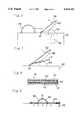
BRIEF DESCRIPTION OF THE DRAWINGS
In the accompanying drawings:
FIG. 1 is a front view showing a preferable embodiment of an apparatus for bending laminated woods according to this invention;
FIG. 2 is an elevation of the apparatus shown in FIG. 1;
FIG. 3 is a partial view showing the position of the heating device;
FIG. 4 is a perspective view showing an embodiment of a convex portion and a concave portion for holding the sheet end portion;
FIG. 5 is a schematic view showing the state in which work (plywood) is set on the mold;
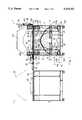
FIG. 6 is a schematic view presenting an conventional apparatus for bending laminated woods;
FIG. 7 is a schematic view of the conventional apparatus wherein a work is set;
FIG. 8 is a cross-sectional view of a plywood as the work in FIG. 7;
FIG. 9 is a schematic representation explaining a forming process using a conventional apparatus;
FIG. 10 is an enlarged cross-sectional view of the portion presented in FIG. 9;
FIG. 11 is an schematic view explaining a negative point of the conventional apparatus; and
FIG. 12 is an schematic view showing another negative point of the conventional apparatus.
DETAILED DESCRIPTION OF THE PREFERABLE EMBODIMENTS
An embodiment of this invention will now be described with reference to drawings.
In the apparatus for bending sheet materials, whose front view is presented in FIG. 1, two same formingunits 1 are juxtaposed. Each formingunit 1 has the same structure so that the description will be performed only for one forming unit (right side) 1. Furthermore, for theleft forming unit 1, only the outline is presented while the mechanical details is omitted in the figure. The formingunit 1 has thebed portion 2 in its lower part. Thebed portion 2 is supported by a frame ofapparatus 4 and is equipped with amold 6. Themold 6 has an almost semicircular cross section and is mainly made of a thick plywood which is supported by a transverse framework which is not presented in the figure. Themold 6 is replaced according to the radius needed for forming the work. Three imaginary lines inside present the shapes of the molds with various sizes.
Avacuum suction device 10, which is mounted on thebed portion 2, has many suction cavities which are not presented in the figure,suction channels 12 leading to the suction cavities, avalve 12a and asuction pump 14 connected with thesuction channels 12. Arubber sheet 16, as a flexible sheet, is sucked to be tightly contacted with the formingsurface 8 by operating thesuction pump 14 and switching thevalve 12a.
Therubber sheet 16 is, for example, rectangular one with a thickness of about 10 mm, whose two opposite longitudinal edges are supported by thesheet supporting device 18. Thesheet supporting device 18 has anplaner type frame 20, which is supported to be movable upwards and downwards, whereby therubber sheet 16 can move to and from themold 6 in a reciprocating motion.
Jack devices 24 are mounted on four comers in the elevation of the frame ofapparatus 20. Thesejack devices 24 comprise four threadedshafts 22 mounted rotatably around perpendicular axes and acommon driving motor 25, which rotates these threadedshafts 22 simultaneously throughtransmission shafts 23. The lower end of each threadedshaft 22 is connected with theportion 24a for transmitting the rotation. Fourbrackets 20a extending downwards are secured to theframe 20, which is supported being screwed on four said threadedshafts 22 throughnuts 20b mounted on the lower end of eachbracket 20a. When each threaded shafts are rotated simultaneously in forward or reverse direction by said drivingmotor 25, theframe 20 moves up or down through the nuts 20b screwed on each threadedshaft 22.
Therubber sheet 16 is supported by theframe 20 through thesheet stretching devices 26 and 28. Thesheet stretching devices 26 and 28 (5 for each) are mounted along the two opposite longitudinal edges of the rubber sheet with the same intervals, respectively, as shown in FIG. 2. As shown in FIG. 1, in thesheet stretching devices 26 for one side,air cylinders 30 are fixed to theframe 20 throughbrackets 32, and clamps 34 mounted on the tip of eachpiston rod 33 are holding the edge portions of therubber sheet 16. In thesheet stretching devices 28 positioned counter to thesheet stretching devices 26,cylinders 36 are secured to theframe 20 withbrackets 38, and clamps 42 are mounted on the tip of eachpiston rod 40. The edge portions of therubber sheet 16 are aligned perpendicularly upwards by aroller 44 and saidclamps 42 clamp the edge portions. When thecylinders 30, 36 of thesheet stretching devices 26, 28 are in the extended position, therubber sheet 16 is relaxed. Contrary to this, when thecylinders 30,36 are in the retracted position, therubber sheet 16 is stretched and the deflection of therubber sheet 16 is absorbed. Thesecylinders 30,36 are connected with a compressed air supplying unit which is not drawn in the figure.
Rod-likeceramic heaters 46 used for far infra-red radiation, and as the second heat source, are horizontally arranged on both insides of the frame so that theheaters 46 face each other at equal distances along the longitudinal direction of therubber sheet 16. Areflector 46a with a cylindrical concavity is equipped behind each rod-likeceramic heater 46. Aheating hood 48, used as a mobile heating device, is mounted over themold 6. Theheating hood 48 is supported movably in the horizontal direction alongguide rails 49, which connects the juxtaposed formingunits 1, thereby thehood 48 functions as a heating device commonly used for two of the formingunits 1.Ceramic heaters 50, used as the first heat source, are arranged on three positions on the inside of theheating hood 48 , i.e., both sides and the center so that theheaters 50 are facing to the formingsurface 8 of themold 6 at a defined distance.Reflectors 50a with cylindrical concavities are behind theceramic heaters 50 in the same construction for theceramic heaters 46 and thereflector 46a. Theceramic heaters 50 on these three positions are arranged at equal distances along the longitudinal direction of themold 6. As is shown in FIG. 3, when theframe 20 is in the position of the lower end of its motion at the side of mold 6 (forming position),ceramic heaters 46 and 50 are facing to the semicircular formingsurface 8 of themold 6 with a almost uniform gap along the circumferential direction. Therefore, the adhesive agent of the work W is uniformly heated through therubber sheet 16, which is tightly contacted with themold 6, and cured.
As shown in FIG. 4, while therubber sheet 16 is extending beyond both ends of the mold in the longitudinal direction,convex portions 54 for holding the edge portions of the rubber sheet are formed on thebed portion 2 being adjacent to both end portions of themold 6. Each convex portion has a smooth sinusoidal convex surface, and the shape and size of cross section of the convex portion is similar to those of themold 6.
On the other hand,concave portions 56 are formed on saidframe 20 facing to the convex portions. The size and shape of theconcave portions 56 are just fitting to those of theconvex portions 54. At the position where theframe 20 reaches to the lower end of its motion, theconvex portions 54 and theconcave portions 56 are engaged each other, and keep the tightness between thebed portion 2 and therubber sheet 16 clipping the rubber sheet between themselves. Accordingly, the appearance of wrinkles on both longitudinal edge portions of the rubber sheet is avoided or suppressed.
Theconvex members 55, on which theconvex portions 54 are formed, are secured with a plurality of bolts and nuts 55a on the end surfaces of themold 6, and are mounted removably through themold 6 on thebed portion 2. On the other hand, theconcave members 57 on which theconcave portions 56 are formed are mounted removably on the lower part of theframe 20 with a plurality of bolts and nuts 57a. When themold 6 is replaced with that having a different radius or a different shape of cross section, the convex andconcave members 55 and 57 are also replaced with those having corresponding size and cross section. In this case, the plurality of bolts and nuts 55a and 57a are once removed, saidconvex members 55 andconcave members 57 are replaced with new ones, and then said plurality of bolts and nuts 55a and 57a are secured again.
In the following part, the operation of the apparatus for bending laminated sheet materials, which is constructed as mentioned above, will be explained.
First of all, the sheet material to be bent, i.e., the work W is set on the mold while theFrame 20 is located at the upper end of its motion (stand-by position) as shown in FIG. 1.
FIG. 8 presents the work W wherein a plurality of elementary boards W1 are laminated with adhesive agent W2 so that the thickness of the work W reaches to a designated value.
As shown in FIG. 5, therubber sheet 16 interferes with the insertion of the work W if the rubber sheet is exhibiting deflection. In this embodiment however, the work W is inserted easily since therubber sheet 16 is stretched from both sides by thecylinders 30 and 36 for avoiding the deflection.
After the setting of the work W, theframe 20 is traversed downwards by thejack devices 24, and thecylinders 30, 36 of thesheet stretching device 26, 28 are extended for relaxing the rubber sheet. Under this state, therubber sheet 16 covers the work W on themold 6 from the upper side. At this time, two longitudinal edge portions of therubber sheet 16 are clipped between theconvex portions 54 andconcave portions 56 presented in FIG. 4, and the tightness between therubber sheet 16 andbed portion 2 is ensured. When thevacuum suction device 10, shown in FIG. 1, is operated while this state is being maintained, therubber sheet 16 is attracted to themold 6 and bends the work W along the formingsurface 8, and the work W is finally maintained tightly contacting with the formingsurface 8 by therubber sheet 16.
Subsequently, theceramic heaters 50 generate heat while theheating hood 48 is placed over themold 6, and the ceramic heaters 46 (FIG. 3 ) on theframe 20 also generate heat so that the work W, which is tightly contacted with themold 6, is heated through therubber sheet 16 from the outside. Consequently, the adhesive agent W2 developed between the elementary boards W1 in the work W is cured by the heating. In other words, the heating is continued until the curing is completed.
When the heating is completed, theheating hood 48 slides to the side of the other formingunit 1. Therubber sheet 16 is released from the vacuum suction, and theframe 20 of FIG. 1 is traversed upwards. At this time, thesheet stretching devices 26, 28 stretch therubber sheet 16 and move up to the upper end of the motion maintaining the state that the deflection of therubber sheet 16 is absorbed. The work W bent is taken out from themold 6, and then the next work is set.
During the setting of the work W, theheating hood 48 is transferred along the guide rails 49 to the other juxtaposed formingunit 1 having the same construction (the work W has already been set in the formingunit 1 to which theheating hood 48 is to be transferred), and the heating process is carried out thereat. Conversely, the setup process, such as setting of the work W, is carried out during the heating for the other formingunit 1.
As it is clear from the description above, in this embodiment therubber sheet 16 is moved up and down, and the deflection of therubber sheet 16 is absorbed during the setting of the work W so that it is easy to set the work W on themold 6, and such problem that the work W once set is dislocated by therubber sheet 16 hardly occurs. Furthermore, wrinkling of the both edge portions of therubber sheet 16 is reduced because of the existence of theconvex portions 54 and theconcave portions 56 for holding the end portions of the rubber sheet.
Although the embodiment mentioned above is constructed so that two formingunits 1 are installed and one heating unit is commonly used by said formingunits 1, a simple construction comprising one formingunit 1 and oneheating hood 48 is possible. A construction comprising no heating devices is also possible for the case that the sheet materials is formed without heating (for example, wherein adhesive agent which hardens at around room temperature within a defined time is developed between elementary boards, and the boards laminated are bent before the adhesive agent hardens). Furthermore, this invention is applicable for bending various sheet materials besides laminated woods.

Claims (14)

That which is claimed is:
1. In an apparatus for forming sheet materials wherein a sheet material is placed on a mold having a convex surface corresponding to the shape to be achieved by forming, wherein a flexible sheet covers said sheet material, and wherein said flexible sheet is tightly contacted with the sheet material by vacuum suction thereby forming said sheet material, said apparatus comprising:
a bed portion supporting said mold;
a sheet supporting member for supporting said flexible sheet in a spread state;
a sheet transporting device for transporting said sheet supporting member to and from said mold in a reciprocating motion;
a sheet stretching device mounted on said sheet supporting member, wherein said sheet stretching device applies a stretching force to said flexible sheet when said sheet supporting member is in a stand-by position remote from the mold and releases the stretching force for giving the flexible sheet deflection when said sheet supporting member is in a forming position near the mold; and
a vacuum suction device mounted on said bed portion.
2. An apparatus for forming laminated sheet materials comprising:
a mold having two end portions and having a convex forming surface corresponding to a shape to be achieved by forming, on which said laminated sheet materials is placed;
a flexible sheet which covers said sheet material on said mold which tightly compresses said laminated sheet materials by use of vacuum suction, and which forms said sheet material;
a bed portion supporting said mold;
a sheet supporting member for supporting said flexible sheet in a spread state;
a sheet transporting device for transporting said sheet supporting member to and from said mold in a reciprocating motion;
convex portions mounted on said bed portion and mounted adjacent to both end portions of said mold, wherein convexities having the same size and shape of cross section as said convex portions are formed on an extension of the forming surface of the mold, and said convexities are facing to edge portions of said flexible sheet;
concave portions which are mounted on said sheet supporting member, and have concavities engaged to said convexities for holding the flexible sheet by clipping end portions of the flexible sheet between said convexities and said concavities; and
a vacuum suction device mounted on said bed portion.
3. In an apparatus for forming sheet materials wherein a sheet material is placed on a mold having two end portions and having a convex forming surface corresponding to the shape to be achieved by forming, wherein a flexible sheet covers said sheet material, and wherein said flexible sheet is tightly contacted with the sheet material by vacuum suction thereby forming said sheet material, said apparatus comprising:
a bed portion supporting said mold;
a sheet supporting member for supporting said flexible sheet in a spread state;
a sheet transporting device for transporting said sheet supporting member to and from said mold in a reciprocating motion;
a sheet stretching device mounted on said sheet supporting member, said sheet stretching device applies a stretching force to said flexible sheet when said sheet supporting member is in a forming position near the mold and;
convex portions mounted on said bed portion and mounted adjacent to both the ends of said mold, wherein convexities having the same size and shape of cross section as said convex portions are formed on an extension of the forming surface of the mold, and said convexities are facing to end portions of said flexible sheet;
concave portions which are mounted on said sheet supporting member, and have concavities engaged to said convexities for holding the flexible sheet by clipping end portions of the flexible sheet between said convexities and said concavities; and
a vacuum suction device mounted on said bed portion.
4. An apparatus for forming laminated sheet materials having a plurality of elementary sheets by using a thermosetting adhesive agent placed on said sheets, which thermosetting adhesive agent is hardened by external heating applied to the laminated sheet materials comprising:
a mold having a convex surface corresponding to a shape to be achieved by forming and on which said laminated sheet materials are placed;
a flexible sheet which covers said laminated sheet materials on said mold, which tightly compresses said laminated sheet materials by use of vacuum suction, which forms said laminated sheet material, and which allows heat to pass through it to provide said external heating;
a bed portion supporting said mold;
a sheet supporting member for supporting said flexible sheet in a spread state;
a sheet transporting device for transporting said sheet supporting member to and from said mold in a reciprocating motion;
a mobile heating device mounted so that it moves crossing the direction in which said sheet transporting device transports said sheet supporting member in a reciprocating motion, and said mobile heating device moves between positions facing to said mold and remote from the mold by a driving unit;
a primary heat source mounted on said mobile heating device for heating the laminated sheet material, which is tightly contacted with a forming surface of said mold by said flexible sheet, from a direction opposed to the mold through said flexible sheet; and
a secondary heat source mounted on said sheet supporting member for heating the laminated sheet material, which is tightly contacted with the forming surface of said mold by said flexible sheet, from both sides of a top surface of said mold convex surface of said laminated sheet material which is to be bent along said convex surface of said mold through said flexible sheet.
5. The apparatus according to claim 2;
wherein a frame of said sheet supporting member is supported by a jack device so that said sheet transporting device can be traversed up and down in a vertical direction,
wherein said jack device is equipped with a plurality of threaded shafts rotatable around vertical axes and a motor for rotating said threaded shafts,
wherein said frame is screwed on said threaded shafts with nuts, and
wherein said frame is traversed up and down by the forward or reverse rotation of said threaded shafts driven by said motor.
6. An apparatus for forming sheet materials comprising:
a mold having a convex surface corresponding to a shape to be achieved by forming and on which said laminated sheet materials are placed;
a flexible sheet which covers said laminated sheet material on said mold, which tightly compresses said laminated sheet material by use of vacuum suction and which forms said laminated sheet material;
a bed portion supporting said mold;
a sheet supporting member for supporting said flexible sheet in a spread state;
a sheet transporting device for transporting said sheet supporting member to and from said mold in a reciprocating motion;
a sheet stretching device mounted on said sheet supporting member, wherein said sheet stretching device applies a stretching force to said flexible sheet when said sheet supporting member is in a stand-by position remote from the mold and releases the stretching force for giving the flexible sheet deflection when said sheet supporting member is in a forming position near the mold; and
a vacuum suction device mounted on said bed portion;
wherein a frame of the sheet supporting member is supported over said bed portion so that said sheet supporting member is movable to and from said mold,
wherein said sheet transporting device raises said frame to said stand-by position and lowers the frame to the forming position,
wherein said sheet stretching device comprises a plurality of linear actuated cylinders which hold at least one edge portion of said flexible sheet,
wherein said stretching cylinders maintain the flexible sheet in a stretched state at a position where said frame reaches to an upper end of its motion and in a relaxed state at a position where said frame reaches to a lower limit of its motion.
7. The apparatus according to claim 2;
wherein a frame of the sheet supporting member is supported over said bed portion so that said sheet supporting member can be traversed up and down in a perpendicular direction,
wherein said sheet transporting device lifts up said frame to a stand-by position and lowers the frame to a forming position,
wherein said convex portions and said concave portions are mounted on said bed portion and on said frame, respectively; and
wherein when said mold is replaced with a mold of different size or shape, said convex portion and said concave portion are also replaced with those corresponding to the mold.
8. The apparatus according to claim 4 further comprising a sheet stretching device mounted on said sheet supporting member, wherein said sheet stretching device applies a stretching force to said flexible sheet when said sheet supporting member is in a stand-by position remote from the mold, and releases a stretching force for giving the flexible sheet deflection when said sheet supporting member is in a forming position near the mold.
9. The apparatus according to claim 4 further comprising:
convex portions mounted on said bed portion and mounted adjacent to both edge portions of said mold, wherein convexities having the same size and shape of cross section as said convex portions are formed nearly on an extension of the forming surface of the mold, and said convexities are facing to edge portions of said flexible sheet; and
concave portions which are mounted on said sheet supporting member, and have concavities engaged to said convexities for holding the flexible sheet by clipping end portions of the flexible sheet between said convexities and said concavities.
10. An apparatus for forming sheet materials comprising:
a mold on which said laminated sheet materials is placed having two end portions and having a convex surface corresponding to a shape to be achieved by forming;
a flexible sheet which covers said laminated sheet material on said mold, which tightly compresses said laminated sheet materials by use of vacuum suction and which forms said laminated sheet materials;
a bed portion supporting said mold;
a sheet supporting member for supporting said flexible sheet in a spread state;
a sheet transporting device for transporting said sheet supporting member to and from said mold in a reciprocating motion;
a sheet stretching device mounted on said sheet supporting member, wherein said stretching device stretches said flexible sheet by moving one edge of said flexible sheet relative to the other edge thereof and thereby decreasing deflection of said flexible sheet due to the weight thereof when said sheet supporting member is in a stand-by position remote from the mold, and said stretching device releases stretching of the flexible sheet when said sheet supporting member is in a forming position near the mold; and
a vacuum suction device mounted on said bed portion.
11. In an apparatus for forming sheet materials wherein a sheet material is placed on a mold having a convex surface corresponding to the shape to be achieved by forming, wherein a flexible sheet covers said sheet material, and wherein said flexible sheet is tightly contacted with the sheet material by vacuum suction thereby forming said sheet material, said apparatus comprising;
a bed portion supporting said mold;
a sheet supporting member for supporting said flexible sheet in a spread state;
a sheet transporting device for transporting said sheet supporting member to and from said mold in a reciprocating motion;
a sheet stretching device mounted on said sheet supporting member, wherein said sheet stretching device supports at least one edge portion of said flexible sheet and moves along the direction of stretching said flexible sheet thereby decreasing a deflection of said flexible sheet when said sheet supporting member is in a stand-by position and said stretching device releases stretching of the flexible sheet when said sheet supporting member is in a forming position; and
a vacuum suction device mounted on said bed portion.
12. In an apparatus for forming sheet materials wherein a sheet material is placed on a mold having a convex surface corresponding to the shape to be achieved by forming, wherein a flexible sheet covers said sheet material, and wherein said flexible sheet is tightly contacted with the sheet material by vacuum suction thereby forming said sheet material, said apparatus comprising;
a bed portion supporting said mold;
a sheet supporting member for supporting said flexible sheet in a spread state;
a sheet transporting device for transporting said sheet supporting member to and from said mold in a vertical reciprocating motion;
a sheet stretching device comprising a plurality of stretching cylinders which hold at least one edge portion of said flexible sheet and move said one edge portion away from the other edge portion thereby stretching said flexible sheet and decreasing deflection thereof, and wherein said stretching cylinders maintain the flexible sheet in a stretched state at a position where said sheet supporting member reaches to an upper end of its motion, and in a relaxed state at a position where said sheet supporting member reaches to a lower limit of its motion; and
a vacuum suction device mounted on said bed portion.
13. An apparatus for forming laminated sheet materials having a plurality of elementary sheets laminated by using a thermosetting adhesive agent placed on said sheets which thermosetting adhesive agent is hardened by external heating of the laminated sheet materials comprising;
a mold having a convex surface corresponding to a shape to be achieved by forming, on which said laminated sheet materials are placed,
a flexible sheet which covers said laminated sheet materials on said mold, which tightly compresses said laminated sheet materials by use of vacuum suction, which forms said laminated sheet material, and which allows heat to pass through it to provide said external heating;
a bed portion supporting said mold;
a sheet supporting member for supporting said flexible sheet in a spread state;
a sheet transporting device for transporting said sheet supporting member to and from said mold in a reciprocating motion;
a mobile heating device mounted so that it moves crossing the direction in which said sheet transporting device transports said sheet supporting member;
a primary heat source mounted on said mobile heating device for heating the laminated sheet material, which is tightly contacted with a forming surface of said mold by said flexible sheet, from a direction opposed to the mold through said flexible sheet; and
a secondary heat source mounted on said sheet supporting member for heating the laminated sheet material, which is tightly contacted with the forming surface of said mold by said flexible sheet, from both sides of a top surface of said mold convex surface of said laminated sheet material which is to be bent along said convex surface of said mold through said flexible sheet.
14. The apparatus according to claim 3;
wherein a frame of said sheet supporting member is supported by a jack device so that said sheet transporting device can be traversed up and down in a vertical direction,
wherein said jack device is equipped with a plurality of threaded shafts rotatable around vertical axes and a motor for rotating said threaded shafts,
wherein said frame is screwed on said threaded shafts with nuts, and
wherein said frame is traversed up and down by the forward or reverse rotation of said threaded shafts driven by said motor.
US08/171,7431993-01-141993-12-22Apparatus for forming sheet materialsExpired - LifetimeUS5464341A (en)

Applications Claiming Priority (2)

Application NumberPriority DateFiling DateTitle
JP5-0220651993-01-14
JP5022065AJP2585175B2 (en)1993-01-141993-01-14 Plate bending machine

Publications (1)

Publication NumberPublication Date
US5464341Atrue US5464341A (en)1995-11-07

Family

ID=12072501

Family Applications (1)

Application NumberTitlePriority DateFiling Date
US08/171,743Expired - LifetimeUS5464341A (en)1993-01-141993-12-22Apparatus for forming sheet materials

Country Status (5)

CountryLink
US (1)US5464341A (en)
JP (1)JP2585175B2 (en)
KR (1)KR970006450B1 (en)
IT (1)IT1269420B (en)
TW (1)TW225500B (en)

Cited By (13)

* Cited by examiner, † Cited by third party
Publication numberPriority datePublication dateAssigneeTitle
EP0778122A3 (en)*1995-10-161998-02-04The Boeing CompanyMethod and apparatus for shaping honeycomb core
US20030034118A1 (en)*2001-08-022003-02-20Lear CorporationShuttle system for manufacturing vehicle headliners
US6814916B2 (en)2002-08-302004-11-09The Boeing CompanyForming method for composites
US20070096369A1 (en)*2005-11-012007-05-03Fox Stone, Inc.Methods and apparatus for the separation of molded products from flexible mold pieces
US20090165957A1 (en)*2008-01-022009-07-02Yuhwen LeeApparatus for laminating substrates
US20100007065A1 (en)*2008-07-112010-01-14Raphael ReinholdDevice for use in the manufacture of fiber-reinforced components
US20100043941A1 (en)*2002-08-302010-02-25The Boeing CompanyComposite Spar Drape Forming Machine
US20120153539A1 (en)*2010-12-152012-06-21The Boeing CompanyAirfoil Manufacturing System
CN105856542A (en)*2016-05-302016-08-17佛山市联智新创科技有限公司Heating, bending and material-taking integrated device for plastic plate
US10011080B2 (en)2014-09-292018-07-03The Boeing CompanyComposite part forming system
US20200023596A1 (en)*2018-07-232020-01-23The Boeing CompanySemi-rigid frame for large vacuum bag deployment in composite manufacturing
CN110962324A (en)*2019-11-072020-04-07杭州中亚机械股份有限公司Cup body forming device
CN117697905A (en)*2023-12-262024-03-15国际竹藤中心Processing equipment for plastic bending and forming of round bamboo

Families Citing this family (4)

* Cited by examiner, † Cited by third party
Publication numberPriority datePublication dateAssigneeTitle
CN104227807B (en)*2014-08-222016-08-24嘉善吉弘机械厂(普通合伙)The turnover panel assembly of plywood hot-pressing machine
CN107486902B (en)*2017-09-212019-04-30重庆市浩源门业有限公司A kind of bending method of plank
CN107650219A (en)*2017-09-212018-02-02重庆市浩源门业有限公司One koji wood machine
CN112959794B (en)*2021-03-312023-08-29秦皇岛金辰太阳能设备有限公司 Movable press frame type lamination machine and rubber sheet press type lamination method

Citations (9)

* Cited by examiner, † Cited by third party
Publication numberPriority datePublication dateAssigneeTitle
US2151880A (en)*1936-07-311939-03-28Firm Fischer & SuffertVeneering press
US2385544A (en)*1943-05-191945-09-25Salisbury Leonard ByronMolding device
US2390684A (en)*1940-12-051945-12-11Langley Aviat CorpVeneer press
US2401299A (en)*1942-10-031946-06-04Universal Moulded Products CorMolding and gluing press
US3466706A (en)*1966-11-081969-09-16Kazuo AsanoClamping device
US3914103A (en)*1974-09-231975-10-21Formex Mfg IncAbstract having product ejection means for forming plastic
US4475976A (en)*1983-12-231984-10-09The Boeing CompanyMethod and apparatus for forming composite material articles
US4608220A (en)*1984-12-201986-08-26The Boeing CompanyMethod of forming composite material articles
JPH03286802A (en)*1990-04-021991-12-17Dantani Plywood Co LtdManufacture of decorative sheet bonded with fancy veneer

Patent Citations (9)

* Cited by examiner, † Cited by third party
Publication numberPriority datePublication dateAssigneeTitle
US2151880A (en)*1936-07-311939-03-28Firm Fischer & SuffertVeneering press
US2390684A (en)*1940-12-051945-12-11Langley Aviat CorpVeneer press
US2401299A (en)*1942-10-031946-06-04Universal Moulded Products CorMolding and gluing press
US2385544A (en)*1943-05-191945-09-25Salisbury Leonard ByronMolding device
US3466706A (en)*1966-11-081969-09-16Kazuo AsanoClamping device
US3914103A (en)*1974-09-231975-10-21Formex Mfg IncAbstract having product ejection means for forming plastic
US4475976A (en)*1983-12-231984-10-09The Boeing CompanyMethod and apparatus for forming composite material articles
US4608220A (en)*1984-12-201986-08-26The Boeing CompanyMethod of forming composite material articles
JPH03286802A (en)*1990-04-021991-12-17Dantani Plywood Co LtdManufacture of decorative sheet bonded with fancy veneer

Cited By (24)

* Cited by examiner, † Cited by third party
Publication numberPriority datePublication dateAssigneeTitle
EP0778122A3 (en)*1995-10-161998-02-04The Boeing CompanyMethod and apparatus for shaping honeycomb core
US20030034118A1 (en)*2001-08-022003-02-20Lear CorporationShuttle system for manufacturing vehicle headliners
US6835266B2 (en)2001-08-022004-12-28Lear CorporationShuttle system for manufacturing vehicle headliners
US8236222B2 (en)2002-08-302012-08-07The Boeing CompanyComposite spar drape forming machine
US6814916B2 (en)2002-08-302004-11-09The Boeing CompanyForming method for composites
US20050053762A1 (en)*2002-08-302005-03-10Willden Kurtis S.Forming method for composites
US20100043941A1 (en)*2002-08-302010-02-25The Boeing CompanyComposite Spar Drape Forming Machine
US8142181B2 (en)2002-08-302012-03-27The Boeing CompanyForming method for composites
US20070096369A1 (en)*2005-11-012007-05-03Fox Stone, Inc.Methods and apparatus for the separation of molded products from flexible mold pieces
US20090165957A1 (en)*2008-01-022009-07-02Yuhwen LeeApparatus for laminating substrates
US9656450B2 (en)2008-01-022017-05-23Tpk Touch Solutions, Inc.Apparatus for laminating substrates
US8556617B2 (en)*2008-07-112013-10-15Broetje Automation GmbhDevice for use in the manufacture of fiber-reinforced components
US20100007065A1 (en)*2008-07-112010-01-14Raphael ReinholdDevice for use in the manufacture of fiber-reinforced components
US20120153539A1 (en)*2010-12-152012-06-21The Boeing CompanyAirfoil Manufacturing System
US8597015B2 (en)*2010-12-152013-12-03The Boeing CompanyAirfoil manufacturing system
US9434117B2 (en)2010-12-152016-09-06The Boeing CompanyAirfoil manufacturing system
US10011080B2 (en)2014-09-292018-07-03The Boeing CompanyComposite part forming system
US10875260B2 (en)2014-09-292020-12-29The Boeing CompanyComposite part forming system
CN105856542A (en)*2016-05-302016-08-17佛山市联智新创科技有限公司Heating, bending and material-taking integrated device for plastic plate
CN105856542B (en)*2016-05-302018-06-26许仙福A kind of plastic plate heats bending feeding all-in-one machine
US20200023596A1 (en)*2018-07-232020-01-23The Boeing CompanySemi-rigid frame for large vacuum bag deployment in composite manufacturing
US10821685B2 (en)*2018-07-232020-11-03The Boeing CompanySemi-rigid frame for large vacuum bag deployment in composite manufacturing
CN110962324A (en)*2019-11-072020-04-07杭州中亚机械股份有限公司Cup body forming device
CN117697905A (en)*2023-12-262024-03-15国际竹藤中心Processing equipment for plastic bending and forming of round bamboo

Also Published As

Publication numberPublication date
ITMI940020A0 (en)1994-01-11
JP2585175B2 (en)1997-02-26
KR970006450B1 (en)1997-04-28
IT1269420B (en)1997-04-01
KR940018175A (en)1994-08-16
JPH06210602A (en)1994-08-02
TW225500B (en)1994-06-21
ITMI940020A1 (en)1995-07-11

Similar Documents

PublicationPublication DateTitle
US5464341A (en)Apparatus for forming sheet materials
US5326249A (en)Apparatus for bending lamellar workpieces
US11097463B2 (en)Device for the uniaxial or biaxial stretching of plastics material portions
RU2508199C2 (en)Method of semi-finished product fabrication from esm laminate with two prepreg layers and process unit to this end
CN117020506A (en)Clamping device with automatic direction adjustment function in vehicle body welding conveying line
JP2010030858A (en)Preliminary bonding method for laminated glass using curved roll
RU2118217C1 (en)Apparatus for corrugating sheet material
KR100844892B1 (en) Device for manufacturing sandwich panels
EP0367441B1 (en)Method for matting
JPH05200852A (en) A method for in-plane bending of a composite material profile composed of long fibers in a thermoplastic matrix.
CN111760767A (en) Vertical UV light source curing device and application method thereof
JP2582335B2 (en) Method and apparatus for molding fiber-reinforced plastic moldings
JP3416198B2 (en) Composite molding equipment
CN111559069A (en) A surface treatment machine for rubber waterstop after forming
CN222665697U (en)Hot bending forming device for glass production
CN119283380B (en) A flip device for automatic floor silent pad laminating machine
CN222780000U (en) A thermoforming device
CN216032474U (en)Deformation stretching equipment for PE pipe
CN117445373B (en)Hot bending device for acrylic plate processing
CN119388738A (en) A biaxial stretching device for polypropylene film processing
CN218227863U (en)UV plastic film curing device
CN219686567U (en) PE pipe mouth correction and rounding device
JPH08132518A (en)Vacuum molding method and clamp assembly to be used therefor
CN116038846B (en)Board back-pressing device
CN222200942U (en)Pine makeup rubber coating rapid-curing cutback device

Legal Events

DateCodeTitleDescription
ASAssignment

Owner name:KABUSHIKI KAISHA TACHIBANA SEISAKUSHO, JAPAN

Free format text:ASSIGNMENT OF ASSIGNORS INTEREST;ASSIGNORS:TACHIBANA, HIROSHI;KIZUKI, HARUMI;REEL/FRAME:006859/0847;SIGNING DATES FROM 19930610 TO 19930614

Owner name:KABUSHIKI KAISHA CHIYODA, JAPAN

Free format text:ASSIGNMENT OF ASSIGNORS INTEREST;ASSIGNORS:TACHIBANA, HIROSHI;KIZUKI, HARUMI;REEL/FRAME:006819/0011;SIGNING DATES FROM 19930610 TO 19930614

STCFInformation on status: patent grant

Free format text:PATENTED CASE

ASAssignment

Owner name:KABUSHIKI KAISHA TACHIBABA SEISAKUSHO, JAPAN

Free format text:CORRECTIVE ASSIGNMENT TO ADD AN ADDITIONAL ASSIGNEE. OF AN ASSIGNMENT WAS PREVIOUSLY RECORDED AT REEL 6819, FRAME 0011;ASSIGNORS:TACHIBANA, HIROSHI;KIAUKI, HARUMI;REEL/FRAME:008065/0307;SIGNING DATES FROM 19930614 TO 19950610

Owner name:KABUSHIKI KAISHA CHIYODA, JAPAN

Free format text:RECORD TO ADD AN ADDITIONAL ASSIGNEE ON A PREVIOUSLY RECORDED DOCUMENT AT REEL 6859 FRAME 847.;ASSIGNORS:TACHIBANA, HIROSHI;KIAUKI, HARUMI;REEL/FRAME:008059/0936;SIGNING DATES FROM 19930614 TO 19950610

Owner name:KABUSHIKI KAISHA TACHIBANA SEISAKUSHO, JAPAN

Free format text:RECORD TO ADD AN ADDITIONAL ASSIGNEE ON A PREVIOUSLY RECORDED DOCUMENT AT REEL 6859 FRAME 847.;ASSIGNORS:TACHIBANA, HIROSHI;KIAUKI, HARUMI;REEL/FRAME:008059/0936;SIGNING DATES FROM 19930614 TO 19950610

Owner name:KABUSHIKI KAISHA CHIYODA, JAPAN

Free format text:CORRECTIVE ASSIGNMENT TO ADD AN ADDITIONAL ASSIGNEE. OF AN ASSIGNMENT WAS PREVIOUSLY RECORDED AT REEL 6819, FRAME 0011;ASSIGNORS:TACHIBANA, HIROSHI;KIAUKI, HARUMI;REEL/FRAME:008065/0307;SIGNING DATES FROM 19930614 TO 19950610

ASAssignment

Owner name:KABUSHIKI KAISHA TACHIBANA SEISAKUSHO, JAPAN

Free format text:ASSIGNMENT OF ASSIGNORS INTEREST;ASSIGNORS:TACHIBANA, HIROSHI;KIZUKI, HARUMI;REEL/FRAME:008442/0537;SIGNING DATES FROM 19930610 TO 19930614

Owner name:KABUSHIKI KAISHA CHIYODA, JAPAN

Free format text:ASSIGNMENT OF ASSIGNORS INTEREST;ASSIGNORS:TACHIBANA, HIROSHI;KIZUKI, HARUMI;REEL/FRAME:008442/0537;SIGNING DATES FROM 19930610 TO 19930614

FPAYFee payment

Year of fee payment:4

FPAYFee payment

Year of fee payment:8

FPAYFee payment

Year of fee payment:12


[8]ページ先頭

©2009-2025 Movatter.jp