US5464146A - Thin film brazing of aluminum shapes - Google Patents
Thin film brazing of aluminum shapesDownload PDFInfo
- Publication number
- US5464146A US5464146AUS08/315,039US31503994AUS5464146AUS 5464146 AUS5464146 AUS 5464146AUS 31503994 AUS31503994 AUS 31503994AUS 5464146 AUS5464146 AUS 5464146A
- Authority
- US
- United States
- Prior art keywords
- aluminum
- shapes
- joint
- silicon
- brazing
- Prior art date
- Legal status (The legal status is an assumption and is not a legal conclusion. Google has not performed a legal analysis and makes no representation as to the accuracy of the status listed.)
- Expired - Lifetime
Links
- 229910052782aluminiumInorganic materials0.000titleclaimsabstractdescription51
- XAGFODPZIPBFFR-UHFFFAOYSA-NaluminiumChemical compound[Al]XAGFODPZIPBFFR-UHFFFAOYSA-N0.000titleclaimsabstractdescription51
- 238000005219brazingMethods0.000titleclaimsabstractdescription29
- 239000010409thin filmSubstances0.000titleclaimsabstractdescription5
- 239000000463materialSubstances0.000claimsabstractdescription34
- 230000005496eutecticsEffects0.000claimsabstractdescription24
- 229910052710siliconInorganic materials0.000claimsabstractdescription23
- 238000000034methodMethods0.000claimsabstractdescription21
- 239000010408filmSubstances0.000claimsabstractdescription15
- 230000000694effectsEffects0.000claimsabstractdescription7
- XUIMIQQOPSSXEZ-UHFFFAOYSA-NSiliconChemical compound[Si]XUIMIQQOPSSXEZ-UHFFFAOYSA-N0.000claimsdescription21
- 239000010703siliconSubstances0.000claimsdescription21
- 238000000151depositionMethods0.000claimsdescription10
- CSDREXVUYHZDNP-UHFFFAOYSA-NalumanylidynesiliconChemical compound[Al].[Si]CSDREXVUYHZDNP-UHFFFAOYSA-N0.000claimsdescription6
- 239000006023eutectic alloySubstances0.000claimsdescription6
- 238000010438heat treatmentMethods0.000claimsdescription6
- 230000008021depositionEffects0.000claimsdescription5
- 238000004544sputter depositionMethods0.000claimsdescription5
- 229910045601alloyInorganic materials0.000claimsdescription4
- 239000000956alloySubstances0.000claimsdescription4
- FJMNNXLGOUYVHO-UHFFFAOYSA-Naluminum zincChemical compound[Al].[Zn]FJMNNXLGOUYVHO-UHFFFAOYSA-N0.000claimsdescription4
- 229910052725zincInorganic materials0.000claimsdescription4
- 239000011701zincSubstances0.000claimsdescription4
- 229910000838Al alloyInorganic materials0.000claimsdescription3
- HCHKCACWOHOZIP-UHFFFAOYSA-NZincChemical compound[Zn]HCHKCACWOHOZIP-UHFFFAOYSA-N0.000claimsdescription3
- 239000010949copperSubstances0.000claimsdescription3
- RYGMFSIKBFXOCR-UHFFFAOYSA-NCopperChemical compound[Cu]RYGMFSIKBFXOCR-UHFFFAOYSA-N0.000claimsdescription2
- 229910052802copperInorganic materials0.000claimsdescription2
- 238000005328electron beam physical vapour depositionMethods0.000claimsdescription2
- 229910052712strontiumInorganic materials0.000claimsdescription2
- CIOAGBVUUVVLOB-UHFFFAOYSA-Nstrontium atomChemical compound[Sr]CIOAGBVUUVVLOB-UHFFFAOYSA-N0.000claimsdescription2
- 238000005275alloyingMethods0.000claims1
- 229910052797bismuthInorganic materials0.000claims1
- JCXGWMGPZLAOME-UHFFFAOYSA-Nbismuth atomChemical compound[Bi]JCXGWMGPZLAOME-UHFFFAOYSA-N0.000claims1
- 230000001737promoting effectEffects0.000claims1
- 239000002210silicon-based materialSubstances0.000claims1
- 238000007740vapor depositionMethods0.000claims1
- 238000005304joiningMethods0.000abstractdescription4
- 229910018137Al-ZnInorganic materials0.000abstractdescription3
- 229910018573Al—ZnInorganic materials0.000abstractdescription3
- 229910018125Al-SiInorganic materials0.000abstractdescription2
- 229910018520Al—SiInorganic materials0.000abstractdescription2
- 239000010410layerSubstances0.000description11
- 238000000576coating methodMethods0.000description7
- 239000011248coating agentSubstances0.000description6
- 239000004615ingredientSubstances0.000description6
- 229910052751metalInorganic materials0.000description6
- 239000002184metalSubstances0.000description6
- 230000013011matingEffects0.000description5
- 230000008018meltingEffects0.000description5
- 238000002844meltingMethods0.000description5
- 238000009792diffusion processMethods0.000description4
- 238000001816coolingMethods0.000description3
- 239000011261inert gasSubstances0.000description3
- 230000003287optical effectEffects0.000description3
- 239000012071phaseSubstances0.000description3
- 230000015572biosynthetic processEffects0.000description2
- 238000005260corrosionMethods0.000description2
- 230000007797corrosionEffects0.000description2
- 230000004907fluxEffects0.000description2
- 238000004519manufacturing processMethods0.000description2
- 239000000155meltSubstances0.000description2
- 150000002739metalsChemical class0.000description2
- 238000005240physical vapour depositionMethods0.000description2
- SKFYTVYMYJCRET-UHFFFAOYSA-Jpotassium;tetrafluoroalumanuideChemical compound[F-].[F-].[F-].[F-].[Al+3].[K+]SKFYTVYMYJCRET-UHFFFAOYSA-J0.000description2
- 239000011856silicon-based particleSubstances0.000description2
- 229910021364Al-Si alloyInorganic materials0.000description1
- 229910018182Al—CuInorganic materials0.000description1
- 229910018507Al—NiInorganic materials0.000description1
- 229910020239KAlF4Inorganic materials0.000description1
- AZDRQVAHHNSJOQ-UHFFFAOYSA-NalumaneChemical group[AlH3]AZDRQVAHHNSJOQ-UHFFFAOYSA-N0.000description1
- 229910002056binary alloyInorganic materials0.000description1
- 150000001875compoundsChemical class0.000description1
- 238000010276constructionMethods0.000description1
- 238000007598dipping methodMethods0.000description1
- 238000004090dissolutionMethods0.000description1
- 238000005566electron beam evaporationMethods0.000description1
- 238000010894electron beam technologyMethods0.000description1
- 238000005516engineering processMethods0.000description1
- 239000007789gasSubstances0.000description1
- 230000002401inhibitory effectEffects0.000description1
- 239000011229interlayerSubstances0.000description1
- 239000007788liquidSubstances0.000description1
- 239000007791liquid phaseSubstances0.000description1
- 229910052749magnesiumInorganic materials0.000description1
- 239000000203mixtureSubstances0.000description1
- 210000002445nippleAnatomy0.000description1
- NJPPVKZQTLUDBO-UHFFFAOYSA-NnovaluronChemical compoundC1=C(Cl)C(OC(F)(F)C(OC(F)(F)F)F)=CC=C1NC(=O)NC(=O)C1=C(F)C=CC=C1FNJPPVKZQTLUDBO-UHFFFAOYSA-N0.000description1
- TWNQGVIAIRXVLR-UHFFFAOYSA-Noxo(oxoalumanyloxy)alumaneChemical compoundO=[Al]O[Al]=OTWNQGVIAIRXVLR-UHFFFAOYSA-N0.000description1
- 238000004806packaging method and processMethods0.000description1
- 239000002245particleSubstances0.000description1
- 230000035515penetrationEffects0.000description1
- 230000000704physical effectEffects0.000description1
- 239000000843powderSubstances0.000description1
- 238000005096rolling processMethods0.000description1
- XUIMIQQOPSSXEZ-IGMARMGPSA-Nsilicon-28 atomChemical compound[28Si]XUIMIQQOPSSXEZ-IGMARMGPSA-N0.000description1
- 238000007751thermal sprayingMethods0.000description1
- 239000011800void materialSubstances0.000description1
- XLYOFNOQVPJJNP-UHFFFAOYSA-NwaterSubstancesOXLYOFNOQVPJJNP-UHFFFAOYSA-N0.000description1
- 238000009736wettingMethods0.000description1
Images


Classifications
- F—MECHANICAL ENGINEERING; LIGHTING; HEATING; WEAPONS; BLASTING
- F28—HEAT EXCHANGE IN GENERAL
- F28D—HEAT-EXCHANGE APPARATUS, NOT PROVIDED FOR IN ANOTHER SUBCLASS, IN WHICH THE HEAT-EXCHANGE MEDIA DO NOT COME INTO DIRECT CONTACT
- F28D1/00—Heat-exchange apparatus having stationary conduit assemblies for one heat-exchange medium only, the media being in contact with different sides of the conduit wall, in which the other heat-exchange medium is a large body of fluid, e.g. domestic or motor car radiators
- F28D1/02—Heat-exchange apparatus having stationary conduit assemblies for one heat-exchange medium only, the media being in contact with different sides of the conduit wall, in which the other heat-exchange medium is a large body of fluid, e.g. domestic or motor car radiators with heat-exchange conduits immersed in the body of fluid
- F28D1/04—Heat-exchange apparatus having stationary conduit assemblies for one heat-exchange medium only, the media being in contact with different sides of the conduit wall, in which the other heat-exchange medium is a large body of fluid, e.g. domestic or motor car radiators with heat-exchange conduits immersed in the body of fluid with tubular conduits
- F28D1/047—Heat-exchange apparatus having stationary conduit assemblies for one heat-exchange medium only, the media being in contact with different sides of the conduit wall, in which the other heat-exchange medium is a large body of fluid, e.g. domestic or motor car radiators with heat-exchange conduits immersed in the body of fluid with tubular conduits the conduits being bent, e.g. in a serpentine or zig-zag
- F28D1/0477—Heat-exchange apparatus having stationary conduit assemblies for one heat-exchange medium only, the media being in contact with different sides of the conduit wall, in which the other heat-exchange medium is a large body of fluid, e.g. domestic or motor car radiators with heat-exchange conduits immersed in the body of fluid with tubular conduits the conduits being bent, e.g. in a serpentine or zig-zag the conduits being bent in a serpentine or zig-zag
- F28D1/0478—Heat-exchange apparatus having stationary conduit assemblies for one heat-exchange medium only, the media being in contact with different sides of the conduit wall, in which the other heat-exchange medium is a large body of fluid, e.g. domestic or motor car radiators with heat-exchange conduits immersed in the body of fluid with tubular conduits the conduits being bent, e.g. in a serpentine or zig-zag the conduits being bent in a serpentine or zig-zag the conduits having a non-circular cross-section
- B—PERFORMING OPERATIONS; TRANSPORTING
- B23—MACHINE TOOLS; METAL-WORKING NOT OTHERWISE PROVIDED FOR
- B23K—SOLDERING OR UNSOLDERING; WELDING; CLADDING OR PLATING BY SOLDERING OR WELDING; CUTTING BY APPLYING HEAT LOCALLY, e.g. FLAME CUTTING; WORKING BY LASER BEAM
- B23K1/00—Soldering, e.g. brazing, or unsoldering
- B23K1/0008—Soldering, e.g. brazing, or unsoldering specially adapted for particular articles or work
- B23K1/0012—Brazing heat exchangers
- F—MECHANICAL ENGINEERING; LIGHTING; HEATING; WEAPONS; BLASTING
- F28—HEAT EXCHANGE IN GENERAL
- F28D—HEAT-EXCHANGE APPARATUS, NOT PROVIDED FOR IN ANOTHER SUBCLASS, IN WHICH THE HEAT-EXCHANGE MEDIA DO NOT COME INTO DIRECT CONTACT
- F28D1/00—Heat-exchange apparatus having stationary conduit assemblies for one heat-exchange medium only, the media being in contact with different sides of the conduit wall, in which the other heat-exchange medium is a large body of fluid, e.g. domestic or motor car radiators
- F28D1/02—Heat-exchange apparatus having stationary conduit assemblies for one heat-exchange medium only, the media being in contact with different sides of the conduit wall, in which the other heat-exchange medium is a large body of fluid, e.g. domestic or motor car radiators with heat-exchange conduits immersed in the body of fluid
- F28D1/04—Heat-exchange apparatus having stationary conduit assemblies for one heat-exchange medium only, the media being in contact with different sides of the conduit wall, in which the other heat-exchange medium is a large body of fluid, e.g. domestic or motor car radiators with heat-exchange conduits immersed in the body of fluid with tubular conduits
- F28D1/053—Heat-exchange apparatus having stationary conduit assemblies for one heat-exchange medium only, the media being in contact with different sides of the conduit wall, in which the other heat-exchange medium is a large body of fluid, e.g. domestic or motor car radiators with heat-exchange conduits immersed in the body of fluid with tubular conduits the conduits being straight
- F—MECHANICAL ENGINEERING; LIGHTING; HEATING; WEAPONS; BLASTING
- F28—HEAT EXCHANGE IN GENERAL
- F28F—DETAILS OF HEAT-EXCHANGE AND HEAT-TRANSFER APPARATUS, OF GENERAL APPLICATION
- F28F1/00—Tubular elements; Assemblies of tubular elements
- F28F1/10—Tubular elements and assemblies thereof with means for increasing heat-transfer area, e.g. with fins, with projections, with recesses
- F28F1/12—Tubular elements and assemblies thereof with means for increasing heat-transfer area, e.g. with fins, with projections, with recesses the means being only outside the tubular element
- F28F1/126—Tubular elements and assemblies thereof with means for increasing heat-transfer area, e.g. with fins, with projections, with recesses the means being only outside the tubular element consisting of zig-zag shaped fins
- F—MECHANICAL ENGINEERING; LIGHTING; HEATING; WEAPONS; BLASTING
- F28—HEAT EXCHANGE IN GENERAL
- F28F—DETAILS OF HEAT-EXCHANGE AND HEAT-TRANSFER APPARATUS, OF GENERAL APPLICATION
- F28F9/00—Casings; Header boxes; Auxiliary supports for elements; Auxiliary members within casings
- F28F9/02—Header boxes; End plates
- F28F9/0246—Arrangements for connecting header boxes with flow lines
Definitions
- This inventionrelates to the technology of cladless brazing of metals, and more particularly to the use of sacrificial films that form a eutectic with the metals to be joined and create a joint.
- the prior arthas generally employed (i) deposition of relatively thick braze material into a joint area, (ii) use of metal structural sheets clad with brazing material, or (iii) liquid phase pressure diffusion brazing of precoated members.
- Deposition of thick brazing materialcan be by thermal spraying of powder (such as in U.S. Pat. No. 4,606,495) or by hot liquid dipping in a molten bath of clad metal.
- a non-uniform thickness of the deposited brazed materialwill often affect physical properties of the joint, producing interfacial flaws.
- Clad brazing sheetsalthough requiring thinner, more uniform layers of brazing material, (see U.S. Pat. No. 4,901,908) restrict and inhibit the type of shapes that can be assembled and structured because the clad brazing sheets are difficult to form into complex shapes (such difficulty is due to the fact that clad layers are rolled bonded to sheet which has limited formability).
- the clad sheetsalso cannot be made to fit certain mating components, such as tubes, because tube fabrication requires a seamless joint which cannot be achieved by rolling sheet into tube. Clad sheets may also more readily contain oxides in the clad layer.
- Pressure diffusion bondingmay also employ clad sheets or braze coated members to affect the joint.
- Use of pressurenot only limits shapes that can be made because of the constraints of how pressure is to be applied, but since diffusion bonding is needed, the type of material that can be used is restricted.
- the brazing materialswere limited to Al-Ni, Al-Zn, or Al-Cu to carry out dissolution of the aluminum in the structural members to be bonded to promote diffusion of the aluminum into binary alloys of the braze material to create a modified interlayer. This is disadvantageous because the components to be brazed must be pressure bonded together to get an effective braze joint; this is most amenable to sheet products, but only in low volumes.
- the inventionin a first aspect, is a method of brazing unclad aluminum shapes to effect an autogenous joint, comprising: (a) depositing a thin film of aluminum eutectic forming material onto a zone of at least one of the shapes to be brazed or joined; (b) placing the shapes in joining relationship to form an assembly with a joint at said zone; and (c) heating said assembly to a temperature to diffuse said eutectic forming material into the aluminum members to form a sacrificial bond between the shapes at said joining zone.
- At least one of the unclad aluminum shapes to be joinedis extruded tubing having a precise diametrical configuration and said film is deposited as a physically vapor deposited layer in a thickness range of 1-50 microns.
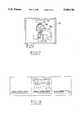
- FIG. 3is a perspective view of an evaporator having plates brazed to tubes and to fins in accordance with this invention
- FIGS. 1 and 2are respectively enlarged sectional views of a portion of FIG. 3 generally taken along line 2--2, each showing the brazing method in sequential steps;
- FIGS. 4a and 4bare schematic illustrations of a prior art louvered fin using braze clad sheets for creating the construction of a perforated or louvered fin plate (FIG. 4a is front elevational and FIG. 4b is side elevational);
- FIG. 5is a schematic view of an evaporator fabricated with extruded multi-channel braze coated tubes, for brazing to corrugated fins, in accordance with this invention
- FIG. 6is an enlarged perspective sectional view of a portion of the coated tube of FIG. 5;
- FIG. 7is a schematic illustration of one method of applying the thin sacrificial film of this invention by physical vapor deposition using electron beam evaporation;
- FIG. 8is a schematic illustration of an alternative physical vapor deposition method for applying the thin sacrificial film using sputter deposition
- FIGS. 9 and 10are respectively longitudinal and cross-sectional views of a tube coated in accordance with this invention employing a thin sacrificial silicon film;
- FIG. 12is a cross sectional view of a clad aluminum sheet containing an aluminum/silicon clad layer composition, all in accordance with the prior art.
- FIG. 13is a simulated optical microphoto of the interfacial bond between the clad sheet of FIG. 12 and the mating plate or sheet to accept the tube.
- the inlet and outlet tubesare welded to the previously brazed heat exchanger using clad sheets of aluminum for the plates and fins.
- the bonding of the inlet or outlet tubes to the header of such heat exchangeris a secondary operation.
- the use of the present inventionallows the entire bonding assembly to take place in one operation reducing the cost of manufacturing.
- a thin sacrificial film 11 of an aluminum eutectic forming materialis deposited onto a selected zone 12 of at least one of the aluminum based members or shapes 13,14 to be joined.
- the aluminum eutectic forming materialis one which forms essentially a eutectic alloy that diffuses into the metal of the member or shapes 13,14 to leave an autogenous bond, such as at 15. There is thus no independent residual brazing material in the bond; the bond is not brittle, has no corrosion and prevents pitting from incomplete brazing.
- the shapes or core membersare preferably formed of 3003 aluminum containing 0.60 Si max, 0.70 Fe max, 0.1-0.30 Cu, 0.15-0.80 Mg, 0.10-0.80 Mn, 0.20 Cr max, 0.05 Ni max, and balance aluminum.
- the eutectic forming material after reacting with aluminummust have a lower melting point than the core metal of the shapes being brazed.
- the materialis preferably silicon, but can be a eutectic comprising material selected from the group consisting of Si, Al-Si (with 8-18% by weight Si), and Al-Zn (with 10-20% Zn).
- the ingredientcan also contain minor amounts (such as 0.1-1.0%) of a flow promoter, such as Bi, Li, Mg, strontium or copper.
- the select zone 12can be the end of an inlet or outlet tube member 13 to be jointed to walls 17 defining a nipple or opening in a header 20 of a heat exchanger 24 (as shown in FIG. 3).
- the heat exchangeris an evaporator comprised of aluminum based plates 20 layered with intervening aluminum-based fins 21.
- the zones of bondingcan also be the contact points or lines 22 between folds or corrugations 23 of the fins 21 and the flat plates 20.
- the film 11can be desirably located only at such intended contact points or lines.
- the aluminum eutectic forming material of the filmpromotes improved bonding by its full or partial sacrificial nature.
- silicon alonethe ingredients diffuse fully into the core aluminum of the members to be joined when heated to a temperature that effects a eutectic aluminum alloy formation.
- About 6% of siliconis soluble in aluminum.
- the aluminum eutectic forming ingredient containing a higher content of silicon in an aluminum alloy form6% of the silicon will migrate into the core aluminum to form a eutectic aluminum phase while the remainder of the Al-Si alloy will reside as a low melting point, essentially eutectic alloy.
- a conventional heat exchangerwill use a braze sheet 16 consisting of a clad aluminum-silicon layer bonded to 3003 type aluminum core.
- louvers 26are stamped out of the clad aluminum brazed sheet 16.
- the function of the louvers 26is to increase surface area and allow air flow through the openings left by the louvers to increase cooling capacity.
- the clad layermelts during brazing, it wicks into the gap 27 between the louver 26 opening and fin 18 to fill such gap and decrease the cooling capacity of the heat exchanger.
- a thin layer of silicon 28can be applied to an extruded multi-channelled tube 29 (see FIGS. 5 and 6) while leaving the fins 30 uncoated.
- the fins 30are joined to the coated extruded tube 29 by application of heat that forms the aluminum eutectic forming phase at contact points 31 to diffuse into the core aluminum of both the fin and the tube.
- the fin materialdoes not need to be clad as with the prior art of FIGS. 4a and 4b.
- the accurately sized extruded tubes 29can be more readily formed into novel shapes allowing for unique heat exchanger designs without inhibiting the ability to braze the assembly or inhibit the ability to form proper shapes. This allows for more flexibility in heat exchanger design for underhood and under-packaging in automotive applications.
- the film 11must be particularly thin, in the range of 1-50 microns. This can be obtained by deposition techniques using electron beam physical vapor deposition or conventional sputtering as shown respectively in FIGS. 7 and 8.
- the tube or fin material 34is placed in a vacuum chamber 35; a supply of the coating material 36, such as silicon, is placed on a pedestal 37 and an electron beam 38 is energized to bombard the supply of silicon to release evaporated particles 39 of the silicon in a vapor form.
- the vaporfinds the target 34 to complete coating in a selected zone.
- the advantages of this deposition techniqueare high deposition rate and uniform coating thickness in the 1-50 micron range.
- Inert gas sputteringcan also be used as illustrated in FIG. 8. This process operates by ionizing an inert gas such as Ar or N 2 , bombarding an electrically biased target with the ionized gas, causing the target to eject material (elemental coating) onto the part being coated as it travels along a conveyor belt.
- an inert gassuch as Ar or N 2
- the members to be joinedAfter the members to be joined have been coated, they are assembled together to create contact there between at their selected coated zones.
- the assembled members or shapesare then heated to a temperature to form a low melting point eutectic alloy of the ingredients with the aluminum shapes such that all or a portion of said eutectic material will diffuse into one or both of the shapes at the zones and fill any space therebetween to effect an autogenous braze joint.
- the heatingis preferably carried out to a temperature in the range of 578°-595° C. when the eutectic forming ingredients are as indicated above consisting of silicon or aluminum silicon, or aluminum zinc.
- Such eutectic forming materialsare most desirable when the core aluminum of the members or shapes to be joined consist of 3003 aluminum.
- Nocolok flux brazingincorporates a water soluble K 3 AlF 6 /KAlF 4 flux compound onto the part being brazed in an inert gas chamber.
- the fluxmelts at 562°-577° C., strips the native aluminum oxide and allows the braze joint to wet mating components to form a braze joint at 578°-595° C.
- FIGS. 9 and 10A schematic of the tube before brazing is shown in FIGS. 9 and 10, and in FIG. 11, a simulated optical microphoto of a cross section of a portion of the joint after brazing is illustrated at a magnification of 100 ⁇ .
- the sacrificial silicon coatinghas reacted with the aluminum from the core alloy, forming a low melting point aluminum-silicon eutectic (fusing at the lowest possible temperature), in which eutectic is diffused into the 3003 aluminum interface, by wetting the mating 3003 sheet and aluminum tube, resulting in the autogenous joint at 53 as illustrated.
- the brazed jointis unique in that no residual silicon is present at the interface between the two mating components indicating that the entire sacrificial silicon layer was consumed during the brazing process.
- This type of brazed jointrepresents a higher quality brazed joint since it is devoid of residual brittle silicon particles typically found in the brazed joint formed using conventional clad brazed sheet.
- FIG. 12shows a simulated microphoto of a cross section of a typical brazed clad 3003 sheet 54 showing the aluminum-silicon clad layer 55 roll bonded to the aluminum sheet (at 100 ⁇ magnification).
- This prior art clad sheet 54is then bonded to a 3003 aluminum tube 56 at openings 57 in the sheet.
- the jointexhibits a microstructure as shown in FIG. 13 (25 ⁇ magnification).
- the dendritic microstructure 60 of the fillet 58 of the brazed jointis apparent along with interfacial voids 59 and silicon particles. There is evidence of excessive grain boundary silicon penetration and interfacial void formation; these represent typical concerns regarding brazed join quality with respect to strength and corrosion resistance.
Landscapes
- Engineering & Computer Science (AREA)
- Physics & Mathematics (AREA)
- Mechanical Engineering (AREA)
- Thermal Sciences (AREA)
- General Engineering & Computer Science (AREA)
- Geometry (AREA)
- Pressure Welding/Diffusion-Bonding (AREA)
- Laminated Bodies (AREA)
Abstract
Description
1. Technical Field
This invention relates to the technology of cladless brazing of metals, and more particularly to the use of sacrificial films that form a eutectic with the metals to be joined and create a joint.
2. Discussion of the Prior Art
The prior art has generally employed (i) deposition of relatively thick braze material into a joint area, (ii) use of metal structural sheets clad with brazing material, or (iii) liquid phase pressure diffusion brazing of precoated members.
Deposition of thick brazing material can be by thermal spraying of powder (such as in U.S. Pat. No. 4,606,495) or by hot liquid dipping in a molten bath of clad metal. A non-uniform thickness of the deposited brazed material will often affect physical properties of the joint, producing interfacial flaws.
Clad brazing sheets, although requiring thinner, more uniform layers of brazing material, (see U.S. Pat. No. 4,901,908) restrict and inhibit the type of shapes that can be assembled and structured because the clad brazing sheets are difficult to form into complex shapes (such difficulty is due to the fact that clad layers are rolled bonded to sheet which has limited formability). The clad sheets also cannot be made to fit certain mating components, such as tubes, because tube fabrication requires a seamless joint which cannot be achieved by rolling sheet into tube. Clad sheets may also more readily contain oxides in the clad layer.
Pressure diffusion bonding may also employ clad sheets or braze coated members to affect the joint. Use of pressure not only limits shapes that can be made because of the constraints of how pressure is to be applied, but since diffusion bonding is needed, the type of material that can be used is restricted. For example, in U.S. Pat. No. 4,890,784, the brazing materials were limited to Al-Ni, Al-Zn, or Al-Cu to carry out dissolution of the aluminum in the structural members to be bonded to promote diffusion of the aluminum into binary alloys of the braze material to create a modified interlayer. This is disadvantageous because the components to be brazed must be pressure bonded together to get an effective braze joint; this is most amenable to sheet products, but only in low volumes.
It is an object of this invention to provide an improved method of brazing two aluminum shapes, particularly for automotive heat exchangers, in which the brazing joint does not leave a physically apparent layer of brazing material and which effects a stronger, sounder joint.
The invention, in a first aspect, is a method of brazing unclad aluminum shapes to effect an autogenous joint, comprising: (a) depositing a thin film of aluminum eutectic forming material onto a zone of at least one of the shapes to be brazed or joined; (b) placing the shapes in joining relationship to form an assembly with a joint at said zone; and (c) heating said assembly to a temperature to diffuse said eutectic forming material into the aluminum members to form a sacrificial bond between the shapes at said joining zone.
It is desirable that at least one of the unclad aluminum shapes to be joined is extruded tubing having a precise diametrical configuration and said film is deposited as a physically vapor deposited layer in a thickness range of 1-50 microns.
FIG. 3 is a perspective view of an evaporator having plates brazed to tubes and to fins in accordance with this invention;
FIGS. 1 and 2 are respectively enlarged sectional views of a portion of FIG. 3 generally taken alongline 2--2, each showing the brazing method in sequential steps;
FIGS. 4a and 4b are schematic illustrations of a prior art louvered fin using braze clad sheets for creating the construction of a perforated or louvered fin plate (FIG. 4a is front elevational and FIG. 4b is side elevational);
FIG. 5 is a schematic view of an evaporator fabricated with extruded multi-channel braze coated tubes, for brazing to corrugated fins, in accordance with this invention;
FIG. 6 is an enlarged perspective sectional view of a portion of the coated tube of FIG. 5;
FIG. 7 is a schematic illustration of one method of applying the thin sacrificial film of this invention by physical vapor deposition using electron beam evaporation;
FIG. 8 is a schematic illustration of an alternative physical vapor deposition method for applying the thin sacrificial film using sputter deposition;
FIGS. 9 and 10 are respectively longitudinal and cross-sectional views of a tube coated in accordance with this invention employing a thin sacrificial silicon film;
FIG. 11 is a simulated sketch of an optical microphoto of the interfacial bond of the coated tube of FIGS. 9 and 10 to the aluminum sheet;
FIG. 12 is a cross sectional view of a clad aluminum sheet containing an aluminum/silicon clad layer composition, all in accordance with the prior art; and
FIG. 13 is a simulated optical microphoto of the interfacial bond between the clad sheet of FIG. 12 and the mating plate or sheet to accept the tube.
In current commercial practice, the inlet and outlet tubes are welded to the previously brazed heat exchanger using clad sheets of aluminum for the plates and fins. Thus the bonding of the inlet or outlet tubes to the header of such heat exchanger is a secondary operation. The use of the present invention allows the entire bonding assembly to take place in one operation reducing the cost of manufacturing.
As shown in FIGS. 1 and 2, a thinsacrificial film 11 of an aluminum eutectic forming material is deposited onto a selectedzone 12 of at least one of the aluminum based members orshapes shapes
Theselect zone 12 can be the end of an inlet oroutlet tube member 13 to be jointed towalls 17 defining a nipple or opening in aheader 20 of a heat exchanger 24 (as shown in FIG. 3). The heat exchanger is an evaporator comprised of aluminum basedplates 20 layered with intervening aluminum-basedfins 21. For this assembly, the zones of bonding can also be the contact points orlines 22 between folds orcorrugations 23 of thefins 21 and theflat plates 20. Thefilm 11 can be desirably located only at such intended contact points or lines.
The aluminum eutectic forming material of the film promotes improved bonding by its full or partial sacrificial nature. With silicon alone, the ingredients diffuse fully into the core aluminum of the members to be joined when heated to a temperature that effects a eutectic aluminum alloy formation. About 6% of silicon is soluble in aluminum. With the aluminum eutectic forming ingredient containing a higher content of silicon in an aluminum alloy form, 6% of the silicon will migrate into the core aluminum to form a eutectic aluminum phase while the remainder of the Al-Si alloy will reside as a low melting point, essentially eutectic alloy. Similarly with the aluminum eutectic forming material containing zinc, some of the zinc will diffuse into the core of the aluminum to form a eutectic aluminum-zinc phase while the remainder of the ingredients remain as a low melting point, essentially eutectic material.
The advantage of this bonding process is that it forms an autogenous joint particularly with heat exchangers such as automotive evaporators; this is apparent when comparing the results to conventional brazing with clad sheets. As shown in FIG. 4a, a conventional heat exchanger will use abraze sheet 16 consisting of a clad aluminum-silicon layer bonded to 3003 type aluminum core. When coolingfins 18 for the heat exchanger are formed,louvers 26 are stamped out of the clad aluminum brazedsheet 16. The function of thelouvers 26 is to increase surface area and allow air flow through the openings left by the louvers to increase cooling capacity. However, when the clad layer melts during brazing, it wicks into thegap 27 between thelouver 26 opening andfin 18 to fill such gap and decrease the cooling capacity of the heat exchanger.
By using the sacrificial thin film cladless coating process described herein, a thin layer ofsilicon 28 can be applied to an extruded multi-channelled tube 29 (see FIGS. 5 and 6) while leaving thefins 30 uncoated. Thefins 30 are joined to the coated extrudedtube 29 by application of heat that forms the aluminum eutectic forming phase at contact points 31 to diffuse into the core aluminum of both the fin and the tube. As mentioned, the fin material does not need to be clad as with the prior art of FIGS. 4a and 4b. Furthermore, the accurately sizedextruded tubes 29 can be more readily formed into novel shapes allowing for unique heat exchanger designs without inhibiting the ability to braze the assembly or inhibit the ability to form proper shapes. This allows for more flexibility in heat exchanger design for underhood and under-packaging in automotive applications.
Thefilm 11 must be particularly thin, in the range of 1-50 microns. This can be obtained by deposition techniques using electron beam physical vapor deposition or conventional sputtering as shown respectively in FIGS. 7 and 8. In FIG. 7, the tube orfin material 34 is placed in avacuum chamber 35; a supply of the coating material 36, such as silicon, is placed on apedestal 37 and an electron beam 38 is energized to bombard the supply of silicon to release evaporatedparticles 39 of the silicon in a vapor form. The vapor finds thetarget 34 to complete coating in a selected zone. The advantages of this deposition technique are high deposition rate and uniform coating thickness in the 1-50 micron range.
Inert gas sputtering can also be used as illustrated in FIG. 8. This process operates by ionizing an inert gas such as Ar or N2, bombarding an electrically biased target with the ionized gas, causing the target to eject material (elemental coating) onto the part being coated as it travels along a conveyor belt.
After the members to be joined have been coated, they are assembled together to create contact there between at their selected coated zones. The assembled members or shapes are then heated to a temperature to form a low melting point eutectic alloy of the ingredients with the aluminum shapes such that all or a portion of said eutectic material will diffuse into one or both of the shapes at the zones and fill any space therebetween to effect an autogenous braze joint. The heating is preferably carried out to a temperature in the range of 578°-595° C. when the eutectic forming ingredients are as indicated above consisting of silicon or aluminum silicon, or aluminum zinc. Such eutectic forming materials are most desirable when the core aluminum of the members or shapes to be joined consist of 3003 aluminum.
To demonstrate proof of principle, an unclad 3003aluminum tube 50 was coated with a one micron thicksacrificial silicon coating 51 and then brazed to an aluminum 3003member 52 using the Nocolok flux brazing process. Nocolok flux brazing incorporates a water soluble K3 AlF6 /KAlF4 flux compound onto the part being brazed in an inert gas chamber. The flux melts at 562°-577° C., strips the native aluminum oxide and allows the braze joint to wet mating components to form a braze joint at 578°-595° C.
A schematic of the tube before brazing is shown in FIGS. 9 and 10, and in FIG. 11, a simulated optical microphoto of a cross section of a portion of the joint after brazing is illustrated at a magnification of 100×. Within the temperature range noted, the sacrificial silicon coating has reacted with the aluminum from the core alloy, forming a low melting point aluminum-silicon eutectic (fusing at the lowest possible temperature), in which eutectic is diffused into the 3003 aluminum interface, by wetting the mating 3003 sheet and aluminum tube, resulting in the autogenous joint at 53 as illustrated. The brazed joint is unique in that no residual silicon is present at the interface between the two mating components indicating that the entire sacrificial silicon layer was consumed during the brazing process. This type of brazed joint represents a higher quality brazed joint since it is devoid of residual brittle silicon particles typically found in the brazed joint formed using conventional clad brazed sheet.
FIG. 12 shows a simulated microphoto of a cross section of a typical brazed clad 3003sheet 54 showing the aluminum-silicon cladlayer 55 roll bonded to the aluminum sheet (at 100× magnification). This prior art cladsheet 54 is then bonded to a 3003aluminum tube 56 atopenings 57 in the sheet. The joint exhibits a microstructure as shown in FIG. 13 (25× magnification). Thedendritic microstructure 60 of thefillet 58 of the brazed joint is apparent along withinterfacial voids 59 and silicon particles. There is evidence of excessive grain boundary silicon penetration and interfacial void formation; these represent typical concerns regarding brazed join quality with respect to strength and corrosion resistance.
Claims (11)
1. A method of brazing unclad first and second aluminum alloy shapes to effect an autogenous joint therebetween, comprising:
depositing a thin sacrificial film of an aluminum eutectic forming material onto a selected zone of at least one of said shapes, the film being effective to uniformly continuously conformed to said zone and form essentially a eutectic alloy with the aluminum of said shapes;
(b) assembling said shapes together to create contact therebetween at said selected zones; and
(c) heating such assembly to a temperature to form a eutectic alloy of said material and the aluminum of said shapes, such alloy migrating into one or both said shapes at said zones, filling any space therebetween to effect an autogenous joint.
2. The method as in claim 1, in which said thin film has a thickness in the range of 1-50 microns.
3. The method as in claim 1, in which said film during the heating step combines with the aluminum of said shapes to form an alloy essentially the same as the alloy of the shapes and thus becomes an autogenous braze joint.
4. The method as in claim 1, in which said alloying material comprises an element selected from the group consisting of silicon, aluminum silicon and aluminum zinc.
5. The method as in claim 4, in which the aluminum silicon material contains 8-18% by weight silicon and the material of aluminum zinc when selected contains 10-20% by weight zinc.
6. The method as in claim 1, in which said deposition of step (a) is carried out by electron beam physical vapor deposition.
7. The method as in claim 1, in which said deposition is carried out by conventional sputtering.
8. The method as in claim 1, in which said heating step is carried out in the temperature range of 578°-595° C. for a period of 1-5 minutes.
9. A method of brazing a tube, plate and fin heat exchanger for automotive applications, comprising:
(a) depositing at joint designated zones on at least one of said tube, plate or fins a thin sacrificial film of silicon in a uniform thickness of 1-50 microns by vapor deposition or sputtering;
(b) forming said tubes, plates and fins into a heat exchanger assembly with said coated zones of said tube, fin or plates in a joint forming relationship with the other of said tube, fin or plate; and
(c) heating such assembly to a temperature to form a eutectic alloy of said silicon and aluminum of the tube, plate or fin so that the eutectic migrates into the aluminum of said tube, plate or fin to form an autogenous joint.
10. The method as in claim 9, in which the forming step employs dies to bend and shape the tubes, plates or fins into the final assembly configuration.
11. The method as in claim 10, in which the thin sacrificial film of silicon additionally contains flow promoting material selected from the group of bismuth, strontium, and copper.
Priority Applications (2)
| Application Number | Priority Date | Filing Date | Title |
|---|---|---|---|
| US08/315,039US5464146A (en) | 1994-09-29 | 1994-09-29 | Thin film brazing of aluminum shapes |
| CA002159247ACA2159247A1 (en) | 1994-09-29 | 1995-09-27 | Thin film brazing of aluminum shapes |
Applications Claiming Priority (1)
| Application Number | Priority Date | Filing Date | Title |
|---|---|---|---|
| US08/315,039US5464146A (en) | 1994-09-29 | 1994-09-29 | Thin film brazing of aluminum shapes |
Publications (1)
| Publication Number | Publication Date |
|---|---|
| US5464146Atrue US5464146A (en) | 1995-11-07 |
Family
ID=23222602
Family Applications (1)
| Application Number | Title | Priority Date | Filing Date |
|---|---|---|---|
| US08/315,039Expired - LifetimeUS5464146A (en) | 1994-09-29 | 1994-09-29 | Thin film brazing of aluminum shapes |
Country Status (2)
| Country | Link |
|---|---|
| US (1) | US5464146A (en) |
| CA (1) | CA2159247A1 (en) |
Cited By (47)
| Publication number | Priority date | Publication date | Assignee | Title |
|---|---|---|---|---|
| EP0958879A3 (en)* | 1998-05-18 | 2001-10-10 | Ford Motor Company | Method for brazing aluminum tube assemblies |
| US20030047588A1 (en)* | 2000-03-29 | 2003-03-13 | Filippov Andrei Gregory | Method of joining metal oilfield tubulars and well provided therewith |
| US6543675B1 (en)* | 1999-02-23 | 2003-04-08 | Valeo Thermique Moteur | Method for soldering an exhaust gas heat exchanger |
| US20030143278A1 (en)* | 2001-12-20 | 2003-07-31 | Femmepharma, Inc. | Vaginal delivery of drugs |
| US20030155409A1 (en)* | 2001-11-21 | 2003-08-21 | Dockus Kostas F. | Fluxless brazing |
| US6623796B1 (en) | 2002-04-05 | 2003-09-23 | Delphi Technologies, Inc. | Method of producing a coating using a kinetic spray process with large particles and nozzles for the same |
| US20030190413A1 (en)* | 2002-04-05 | 2003-10-09 | Van Steenkiste Thomas Hubert | Method of maintaining a non-obstructed interior opening in kinetic spray nozzles |
| US6682774B2 (en) | 2002-06-07 | 2004-01-27 | Delphi Technologies, Inc. | Direct application of catalysts to substrates for treatment of the atmosphere |
| US6685988B2 (en) | 2001-10-09 | 2004-02-03 | Delphi Technologies, Inc. | Kinetic sprayed electrical contacts on conductive substrates |
| US20040035911A1 (en)* | 2001-11-21 | 2004-02-26 | Dockus Kostas F. | Fluxless brazing |
| US20040038070A1 (en)* | 2001-11-21 | 2004-02-26 | Dockus Kostas F. | Fluxless brazing |
| US20040035910A1 (en)* | 2001-11-21 | 2004-02-26 | Dockus Kostas F. | Low temperature fluxless brazing |
| US20040058064A1 (en)* | 2002-09-23 | 2004-03-25 | Delphi Technologies, Inc. | Spray system with combined kinetic spray and thermal spray ability |
| US20040058065A1 (en)* | 2002-09-23 | 2004-03-25 | Steenkiste Thomas Hubert Van | Spray system with combined kinetic spray and thermal spray ability |
| US20040065432A1 (en)* | 2002-10-02 | 2004-04-08 | Smith John R. | High performance thermal stack for electrical components |
| US20040101620A1 (en)* | 2002-11-22 | 2004-05-27 | Elmoursi Alaa A. | Method for aluminum metalization of ceramics for power electronics applications |
| US20040142198A1 (en)* | 2003-01-21 | 2004-07-22 | Thomas Hubert Van Steenkiste | Magnetostrictive/magnetic material for use in torque sensors |
| US20040187605A1 (en)* | 2003-03-28 | 2004-09-30 | Malakondaiah Naidu | Integrating fluxgate for magnetostrictive torque sensors |
| US6808817B2 (en) | 2002-03-15 | 2004-10-26 | Delphi Technologies, Inc. | Kinetically sprayed aluminum metal matrix composites for thermal management |
| US6811812B2 (en) | 2002-04-05 | 2004-11-02 | Delphi Technologies, Inc. | Low pressure powder injection method and system for a kinetic spray process |
| US6821558B2 (en) | 2002-07-24 | 2004-11-23 | Delphi Technologies, Inc. | Method for direct application of flux to a brazing surface |
| US20050040260A1 (en)* | 2003-08-21 | 2005-02-24 | Zhibo Zhao | Coaxial low pressure injection method and a gas collimator for a kinetic spray nozzle |
| US6872427B2 (en) | 2003-02-07 | 2005-03-29 | Delphi Technologies, Inc. | Method for producing electrical contacts using selective melting and a low pressure kinetic spray process |
| US20050074560A1 (en)* | 2003-10-02 | 2005-04-07 | Fuller Brian K. | Correcting defective kinetically sprayed surfaces |
| US20050100489A1 (en)* | 2003-10-30 | 2005-05-12 | Steenkiste Thomas H.V. | Method for securing ceramic structures and forming electrical connections on the same |
| US20050160834A1 (en)* | 2004-01-23 | 2005-07-28 | Nehl Thomas W. | Assembly for measuring movement of and a torque applied to a shaft |
| US6949300B2 (en) | 2001-08-15 | 2005-09-27 | Delphi Technologies, Inc. | Product and method of brazing using kinetic sprayed coatings |
| US20050214474A1 (en)* | 2004-03-24 | 2005-09-29 | Taeyoung Han | Kinetic spray nozzle system design |
| US20060027625A1 (en)* | 2001-11-21 | 2006-02-09 | Dana Canada Corporation | Products for use in low temperature fluxless brazing |
| US20060040048A1 (en)* | 2004-08-23 | 2006-02-23 | Taeyoung Han | Continuous in-line manufacturing process for high speed coating deposition via a kinetic spray process |
| US20060038044A1 (en)* | 2004-08-23 | 2006-02-23 | Van Steenkiste Thomas H | Replaceable throat insert for a kinetic spray nozzle |
| US20060102696A1 (en)* | 2001-11-21 | 2006-05-18 | Graham Michael E | Layered products for fluxless brazing of substrates |
| US20060113359A1 (en)* | 2004-11-30 | 2006-06-01 | Teets Richard E | Secure physical connections formed by a kinetic spray process |
| US20070000969A1 (en)* | 2005-06-20 | 2007-01-04 | Mittlefehldt Kurt R | Brazed aluminum structure and method for forming same |
| US20070074656A1 (en)* | 2005-10-04 | 2007-04-05 | Zhibo Zhao | Non-clogging powder injector for a kinetic spray nozzle system |
| WO2007087822A1 (en)* | 2006-01-31 | 2007-08-09 | Norsk Hydro Asa | A process for making a heat exchanger |
| US20070215674A1 (en)* | 2004-09-22 | 2007-09-20 | Furukawa-Sky Aluminum Corp. | Method of brazing an aluminum alloy material and method of producing an aluminum alloy heat exchanger |
| WO2007096700A3 (en)* | 2006-02-23 | 2007-12-21 | Valmex S P A | Heat exchanger for domestic boilers, especially wall-mounted gas boilers |
| US20080014031A1 (en)* | 2006-07-14 | 2008-01-17 | Thomas Hubert Van Steenkiste | Feeder apparatus for controlled supply of feedstock |
| US7476422B2 (en) | 2002-05-23 | 2009-01-13 | Delphi Technologies, Inc. | Copper circuit formed by kinetic spray |
| US7475831B2 (en) | 2004-01-23 | 2009-01-13 | Delphi Technologies, Inc. | Modified high efficiency kinetic spray nozzle |
| US20090068446A1 (en)* | 2007-04-30 | 2009-03-12 | United Technologies Corporation | Layered structures with integral brazing materials |
| US20110192581A1 (en)* | 2007-12-18 | 2011-08-11 | Showa Denko K.K. | Process for producing member for heat exchanger and member for heat exchanger |
| CN102310287A (en)* | 2010-06-14 | 2012-01-11 | 通用汽车环球科技运作有限责任公司 | Through reacting the joint of metallurgical battery-terminal |
| CN103079744A (en)* | 2010-08-31 | 2013-05-01 | 日产自动车株式会社 | Method for bonding aluminum-based metals |
| US20130319569A1 (en)* | 2010-12-28 | 2013-12-05 | Daikin Industries, Ltd. | Joint structure for metallic pipes |
| FR3009985A1 (en)* | 2013-08-30 | 2015-03-06 | Fives Cryo | DEPOSITION OF SOLDER BY CATHODE SPRAYING OR CHEMICAL DEPOSITION |
Citations (12)
| Publication number | Priority date | Publication date | Assignee | Title |
|---|---|---|---|---|
| US4010530A (en)* | 1975-07-24 | 1977-03-08 | United Technologies Corporation | Method for making blade protective sheaths |
| US4011982A (en)* | 1975-09-15 | 1977-03-15 | Airco, Inc. | Surface joining by bonding of metal and deposited metal |
| US4606495A (en)* | 1983-12-22 | 1986-08-19 | United Technologies Corporation | Uniform braze application process |
| US4681251A (en)* | 1981-06-09 | 1987-07-21 | Tokyo Shibaura Denki Kabushiki Kaisha | Method of joining Ni-base heat resisting alloys |
| US4831701A (en)* | 1985-02-12 | 1989-05-23 | Sanden Corporation | Method of making a corrosion resistant aluminum heat exchanger using a particulate flux |
| US4890784A (en)* | 1983-03-28 | 1990-01-02 | Rockwell International Corporation | Method for diffusion bonding aluminum |
| US4891275A (en)* | 1982-10-29 | 1990-01-02 | Norsk Hydro A.S. | Aluminum shapes coated with brazing material and process of coating |
| US4901908A (en)* | 1987-09-09 | 1990-02-20 | Nippondenso Co., Ltd. | Aluminum material for brazing, method of manufacturing same, and method of manufacturing heat exchanger made of aluminum alloy |
| US4978051A (en)* | 1986-12-31 | 1990-12-18 | General Electric Co. | X-ray tube target |
| US5072789A (en)* | 1989-12-08 | 1991-12-17 | Showa Aluminum Corporation | Heat exchanger made of aluminum |
| US5083697A (en)* | 1990-02-14 | 1992-01-28 | Difrancesco Louis | Particle-enhanced joining of metal surfaces |
| US5100048A (en)* | 1991-01-25 | 1992-03-31 | Alcan International Limited | Method of brazing aluminum |
- 1994
- 1994-09-29USUS08/315,039patent/US5464146A/ennot_activeExpired - Lifetime
- 1995
- 1995-09-27CACA002159247Apatent/CA2159247A1/ennot_activeAbandoned
Patent Citations (13)
| Publication number | Priority date | Publication date | Assignee | Title |
|---|---|---|---|---|
| US4010530A (en)* | 1975-07-24 | 1977-03-08 | United Technologies Corporation | Method for making blade protective sheaths |
| US4011982A (en)* | 1975-09-15 | 1977-03-15 | Airco, Inc. | Surface joining by bonding of metal and deposited metal |
| US4681251A (en)* | 1981-06-09 | 1987-07-21 | Tokyo Shibaura Denki Kabushiki Kaisha | Method of joining Ni-base heat resisting alloys |
| US4891275A (en)* | 1982-10-29 | 1990-01-02 | Norsk Hydro A.S. | Aluminum shapes coated with brazing material and process of coating |
| US4890784A (en)* | 1983-03-28 | 1990-01-02 | Rockwell International Corporation | Method for diffusion bonding aluminum |
| US4606495A (en)* | 1983-12-22 | 1986-08-19 | United Technologies Corporation | Uniform braze application process |
| US4831701A (en)* | 1985-02-12 | 1989-05-23 | Sanden Corporation | Method of making a corrosion resistant aluminum heat exchanger using a particulate flux |
| US4978051A (en)* | 1986-12-31 | 1990-12-18 | General Electric Co. | X-ray tube target |
| US4901908A (en)* | 1987-09-09 | 1990-02-20 | Nippondenso Co., Ltd. | Aluminum material for brazing, method of manufacturing same, and method of manufacturing heat exchanger made of aluminum alloy |
| US5072789A (en)* | 1989-12-08 | 1991-12-17 | Showa Aluminum Corporation | Heat exchanger made of aluminum |
| US5083697A (en)* | 1990-02-14 | 1992-01-28 | Difrancesco Louis | Particle-enhanced joining of metal surfaces |
| US5100048A (en)* | 1991-01-25 | 1992-03-31 | Alcan International Limited | Method of brazing aluminum |
| US5190596A (en)* | 1991-01-25 | 1993-03-02 | Alcan International Limited | Method of brazing metal surfaces |
Cited By (84)
| Publication number | Priority date | Publication date | Assignee | Title |
|---|---|---|---|---|
| EP0958879A3 (en)* | 1998-05-18 | 2001-10-10 | Ford Motor Company | Method for brazing aluminum tube assemblies |
| US6543675B1 (en)* | 1999-02-23 | 2003-04-08 | Valeo Thermique Moteur | Method for soldering an exhaust gas heat exchanger |
| US20030047588A1 (en)* | 2000-03-29 | 2003-03-13 | Filippov Andrei Gregory | Method of joining metal oilfield tubulars and well provided therewith |
| US6860420B2 (en)* | 2000-03-29 | 2005-03-01 | Shell Oil Company | Method of joining metal oilfield tubulars and well provided therewith |
| US6949300B2 (en) | 2001-08-15 | 2005-09-27 | Delphi Technologies, Inc. | Product and method of brazing using kinetic sprayed coatings |
| US6685988B2 (en) | 2001-10-09 | 2004-02-03 | Delphi Technologies, Inc. | Kinetic sprayed electrical contacts on conductive substrates |
| US7001671B2 (en) | 2001-10-09 | 2006-02-21 | Delphi Technologies, Inc. | Kinetic sprayed electrical contacts on conductive substrates |
| US20040072008A1 (en)* | 2001-10-09 | 2004-04-15 | Delphi Technologies, Inc. | Kinetic sprayed electrical contacts on conductive substrates |
| US20030155409A1 (en)* | 2001-11-21 | 2003-08-21 | Dockus Kostas F. | Fluxless brazing |
| US20030189082A1 (en)* | 2001-11-21 | 2003-10-09 | Dockus Kostas F. | Alloy composition and method for low temperature fluxless brazing |
| US20030197050A1 (en)* | 2001-11-21 | 2003-10-23 | Graham Michael E. | Fluxless brazing method and compositions of layered material systems for brazing aluminum or dissimilar metals |
| US20040035911A1 (en)* | 2001-11-21 | 2004-02-26 | Dockus Kostas F. | Fluxless brazing |
| US20060102696A1 (en)* | 2001-11-21 | 2006-05-18 | Graham Michael E | Layered products for fluxless brazing of substrates |
| US20040035910A1 (en)* | 2001-11-21 | 2004-02-26 | Dockus Kostas F. | Low temperature fluxless brazing |
| US20060027625A1 (en)* | 2001-11-21 | 2006-02-09 | Dana Canada Corporation | Products for use in low temperature fluxless brazing |
| US7735718B2 (en) | 2001-11-21 | 2010-06-15 | Dana Canada Corporation | Layered products for fluxless brazing of substrates |
| US6959853B2 (en) | 2001-11-21 | 2005-11-01 | Dana Canada Corporation | Fluxless brazing method and method for manufacturing layered material systems for fluxless brazing |
| US20100086802A1 (en)* | 2001-11-21 | 2010-04-08 | Graham Michael E | Layered products for fluxless brazing of substrates |
| US7000823B2 (en) | 2001-11-21 | 2006-02-21 | Dana Canada Corporation | Fluxless brazing |
| US6815086B2 (en) | 2001-11-21 | 2004-11-09 | Dana Canada Corporation | Methods for fluxless brazing |
| US7451906B2 (en) | 2001-11-21 | 2008-11-18 | Dana Canada Corporation | Products for use in low temperature fluxless brazing |
| EP2070637A1 (en) | 2001-11-21 | 2009-06-17 | Dana Canada Corporation | Product and method for low temperature fluxless brazing |
| US20040038070A1 (en)* | 2001-11-21 | 2004-02-26 | Dockus Kostas F. | Fluxless brazing |
| US6913184B2 (en) | 2001-11-21 | 2005-07-05 | Dana Canada Corporation | Alloy composition and method for low temperature fluxless brazing |
| US20030143278A1 (en)* | 2001-12-20 | 2003-07-31 | Femmepharma, Inc. | Vaginal delivery of drugs |
| US20050085030A1 (en)* | 2002-03-15 | 2005-04-21 | Delphi Technologies, Inc. | Kinetically sprayed aluminum metal matrix composites for thermal management |
| US6808817B2 (en) | 2002-03-15 | 2004-10-26 | Delphi Technologies, Inc. | Kinetically sprayed aluminum metal matrix composites for thermal management |
| US7081376B2 (en) | 2002-03-15 | 2006-07-25 | Delphi Technologies, Inc. | Kinetically sprayed aluminum metal matrix composites for thermal management |
| US6811812B2 (en) | 2002-04-05 | 2004-11-02 | Delphi Technologies, Inc. | Low pressure powder injection method and system for a kinetic spray process |
| US6623796B1 (en) | 2002-04-05 | 2003-09-23 | Delphi Technologies, Inc. | Method of producing a coating using a kinetic spray process with large particles and nozzles for the same |
| US20030190413A1 (en)* | 2002-04-05 | 2003-10-09 | Van Steenkiste Thomas Hubert | Method of maintaining a non-obstructed interior opening in kinetic spray nozzles |
| US6896933B2 (en) | 2002-04-05 | 2005-05-24 | Delphi Technologies, Inc. | Method of maintaining a non-obstructed interior opening in kinetic spray nozzles |
| US7476422B2 (en) | 2002-05-23 | 2009-01-13 | Delphi Technologies, Inc. | Copper circuit formed by kinetic spray |
| US6682774B2 (en) | 2002-06-07 | 2004-01-27 | Delphi Technologies, Inc. | Direct application of catalysts to substrates for treatment of the atmosphere |
| US6821558B2 (en) | 2002-07-24 | 2004-11-23 | Delphi Technologies, Inc. | Method for direct application of flux to a brazing surface |
| US20050087587A1 (en)* | 2002-07-24 | 2005-04-28 | Delphi Technologies, Inc. | Method for direct application of flux to a brazing surface |
| US20040058065A1 (en)* | 2002-09-23 | 2004-03-25 | Steenkiste Thomas Hubert Van | Spray system with combined kinetic spray and thermal spray ability |
| US7108893B2 (en) | 2002-09-23 | 2006-09-19 | Delphi Technologies, Inc. | Spray system with combined kinetic spray and thermal spray ability |
| US6743468B2 (en) | 2002-09-23 | 2004-06-01 | Delphi Technologies, Inc. | Method of coating with combined kinetic spray and thermal spray |
| US20040058064A1 (en)* | 2002-09-23 | 2004-03-25 | Delphi Technologies, Inc. | Spray system with combined kinetic spray and thermal spray ability |
| US20040065432A1 (en)* | 2002-10-02 | 2004-04-08 | Smith John R. | High performance thermal stack for electrical components |
| US20040101620A1 (en)* | 2002-11-22 | 2004-05-27 | Elmoursi Alaa A. | Method for aluminum metalization of ceramics for power electronics applications |
| US20040142198A1 (en)* | 2003-01-21 | 2004-07-22 | Thomas Hubert Van Steenkiste | Magnetostrictive/magnetic material for use in torque sensors |
| US6872427B2 (en) | 2003-02-07 | 2005-03-29 | Delphi Technologies, Inc. | Method for producing electrical contacts using selective melting and a low pressure kinetic spray process |
| US6871553B2 (en) | 2003-03-28 | 2005-03-29 | Delphi Technologies, Inc. | Integrating fluxgate for magnetostrictive torque sensors |
| US20040187605A1 (en)* | 2003-03-28 | 2004-09-30 | Malakondaiah Naidu | Integrating fluxgate for magnetostrictive torque sensors |
| US20050103126A1 (en)* | 2003-03-28 | 2005-05-19 | Delphi Technologies, Inc. | Integrating fluxgate for magnetostrictive torque sensors |
| US20050040260A1 (en)* | 2003-08-21 | 2005-02-24 | Zhibo Zhao | Coaxial low pressure injection method and a gas collimator for a kinetic spray nozzle |
| US20050074560A1 (en)* | 2003-10-02 | 2005-04-07 | Fuller Brian K. | Correcting defective kinetically sprayed surfaces |
| US7351450B2 (en) | 2003-10-02 | 2008-04-01 | Delphi Technologies, Inc. | Correcting defective kinetically sprayed surfaces |
| US7335341B2 (en) | 2003-10-30 | 2008-02-26 | Delphi Technologies, Inc. | Method for securing ceramic structures and forming electrical connections on the same |
| US20050100489A1 (en)* | 2003-10-30 | 2005-05-12 | Steenkiste Thomas H.V. | Method for securing ceramic structures and forming electrical connections on the same |
| US7024946B2 (en) | 2004-01-23 | 2006-04-11 | Delphi Technologies, Inc. | Assembly for measuring movement of and a torque applied to a shaft |
| US20050160834A1 (en)* | 2004-01-23 | 2005-07-28 | Nehl Thomas W. | Assembly for measuring movement of and a torque applied to a shaft |
| US7475831B2 (en) | 2004-01-23 | 2009-01-13 | Delphi Technologies, Inc. | Modified high efficiency kinetic spray nozzle |
| US20050214474A1 (en)* | 2004-03-24 | 2005-09-29 | Taeyoung Han | Kinetic spray nozzle system design |
| US20060038044A1 (en)* | 2004-08-23 | 2006-02-23 | Van Steenkiste Thomas H | Replaceable throat insert for a kinetic spray nozzle |
| US20060040048A1 (en)* | 2004-08-23 | 2006-02-23 | Taeyoung Han | Continuous in-line manufacturing process for high speed coating deposition via a kinetic spray process |
| US8113414B2 (en)* | 2004-09-22 | 2012-02-14 | Furukawa-Sky Alumnum Corp. | Method of brazing an aluminum alloy material and method of producing an aluminum alloy heat exchanger |
| US20070215674A1 (en)* | 2004-09-22 | 2007-09-20 | Furukawa-Sky Aluminum Corp. | Method of brazing an aluminum alloy material and method of producing an aluminum alloy heat exchanger |
| US7900812B2 (en) | 2004-11-30 | 2011-03-08 | Enerdel, Inc. | Secure physical connections formed by a kinetic spray process |
| US20060113359A1 (en)* | 2004-11-30 | 2006-06-01 | Teets Richard E | Secure physical connections formed by a kinetic spray process |
| US20070000969A1 (en)* | 2005-06-20 | 2007-01-04 | Mittlefehldt Kurt R | Brazed aluminum structure and method for forming same |
| US20070074656A1 (en)* | 2005-10-04 | 2007-04-05 | Zhibo Zhao | Non-clogging powder injector for a kinetic spray nozzle system |
| WO2007087822A1 (en)* | 2006-01-31 | 2007-08-09 | Norsk Hydro Asa | A process for making a heat exchanger |
| WO2007096700A3 (en)* | 2006-02-23 | 2007-12-21 | Valmex S P A | Heat exchanger for domestic boilers, especially wall-mounted gas boilers |
| US20080014031A1 (en)* | 2006-07-14 | 2008-01-17 | Thomas Hubert Van Steenkiste | Feeder apparatus for controlled supply of feedstock |
| US7674076B2 (en) | 2006-07-14 | 2010-03-09 | F. W. Gartner Thermal Spraying, Ltd. | Feeder apparatus for controlled supply of feedstock |
| US20090068446A1 (en)* | 2007-04-30 | 2009-03-12 | United Technologies Corporation | Layered structures with integral brazing materials |
| EP1987903B2 (en)† | 2007-04-30 | 2022-07-27 | Raytheon Technologies Corporation | Method for manufacturing a turbine engine component |
| US8413877B2 (en) | 2007-04-30 | 2013-04-09 | United Technologies Corporation | Layered structures with integral brazing materials |
| EP1987903B1 (en) | 2007-04-30 | 2015-11-11 | United Technologies Corporation | Method for manufacturing a turbine engine component |
| US8661675B2 (en)* | 2007-12-18 | 2014-03-04 | Showa Denko K.K. | Process for producing member for heat exchanger and member for heat exchanger |
| US20110192581A1 (en)* | 2007-12-18 | 2011-08-11 | Showa Denko K.K. | Process for producing member for heat exchanger and member for heat exchanger |
| US8590768B2 (en)* | 2010-06-14 | 2013-11-26 | GM Global Technology Operations LLC | Battery tab joint by reaction metallurgy |
| CN102310287B (en)* | 2010-06-14 | 2015-06-17 | 通用汽车环球科技运作有限责任公司 | Battery tab joint by reaction metallurgy |
| DE102011103617B4 (en)* | 2010-06-14 | 2016-05-12 | GM Global Technology Operations LLC (n. d. Ges. d. Staates Delaware) | Method for forming a solid-state welded joint |
| CN102310287A (en)* | 2010-06-14 | 2012-01-11 | 通用汽车环球科技运作有限责任公司 | Through reacting the joint of metallurgical battery-terminal |
| US20140030634A1 (en)* | 2010-08-31 | 2014-01-30 | Nissan Motor Co., Ltd. | Method for bonding aluminum-based metals |
| CN103079744A (en)* | 2010-08-31 | 2013-05-01 | 日产自动车株式会社 | Method for bonding aluminum-based metals |
| US10556292B2 (en)* | 2010-08-31 | 2020-02-11 | Nissan Motor Co., Ltd. | Method for bonding aluminum-based metals |
| US20130319569A1 (en)* | 2010-12-28 | 2013-12-05 | Daikin Industries, Ltd. | Joint structure for metallic pipes |
| US9803781B2 (en)* | 2010-12-28 | 2017-10-31 | Daikin Industries, Ltd. | Joint structure for metallic pipes |
| FR3009985A1 (en)* | 2013-08-30 | 2015-03-06 | Fives Cryo | DEPOSITION OF SOLDER BY CATHODE SPRAYING OR CHEMICAL DEPOSITION |
Also Published As
| Publication number | Publication date |
|---|---|
| CA2159247A1 (en) | 1996-03-30 |
Similar Documents
| Publication | Publication Date | Title |
|---|---|---|
| US5464146A (en) | Thin film brazing of aluminum shapes | |
| US5894054A (en) | Aluminum components coated with zinc-antimony alloy for manufacturing assemblies by CAB brazing | |
| US5692300A (en) | Method for forming aluminum tubes and brazing a lockseam formed therein | |
| US4901908A (en) | Aluminum material for brazing, method of manufacturing same, and method of manufacturing heat exchanger made of aluminum alloy | |
| US4732311A (en) | Process of producing lightweight and corrosion-resistant heat exchanger | |
| US4716959A (en) | Aluminum heat exchangers and method for producing the same | |
| US5295302A (en) | Method of manufacturing an aluminum heat exchanger | |
| US6234243B1 (en) | Heat exchanger assembly with magnesium barrier | |
| KR20180128505A (en) | Solderable fluid channel for a heat exchanger of aluminium | |
| JP3328923B2 (en) | Manufacturing method of aluminum heat exchanger core | |
| JP4560902B2 (en) | Heat exchanger and manufacturing method thereof | |
| US4587701A (en) | Method for producing an aluminum heat exchanger | |
| JP2002361405A (en) | Method for manufacturing heat exchanger | |
| US4571352A (en) | Method for coating aluminum metal body with aluminum alloy brazing filler metal | |
| EP1004390A1 (en) | Method of making a braze sheet | |
| EP0867682A2 (en) | Al-alloy heat exchanger | |
| JP2577962B2 (en) | Aluminum heat exchanger | |
| US20190105742A1 (en) | Method for manufacturing heat exchanger | |
| GB2364010A (en) | Method of short-time brazing for aluminium alloy assembly and low temperature brazing filler alloy | |
| EP1004386A1 (en) | Brazed assembly and method of making same | |
| GB2387136A (en) | High strength CAB brazed heat exchangers using high strength fin materials | |
| KR20010062366A (en) | Flux for cab brazing aluminum heat exchangers | |
| JP5101812B2 (en) | High corrosion resistance tube for heat exchanger, heat exchanger and method for producing the same | |
| JPS6334495A (en) | Aluminum heat exchanger | |
| JP3699202B2 (en) | Aluminum heat exchanger with excellent corrosion resistance and method for producing the same |
Legal Events
| Date | Code | Title | Description |
|---|---|---|---|
| AS | Assignment | Owner name:FORD MOTOR COMPANY Free format text:ASSIGNMENT OF ASSIGNORS INTEREST;ASSIGNORS:ZALUZEC, MATTHEW JOHN;GRAB, GERALD ADAM;SMITH, WARREN ALBERT;REEL/FRAME:007412/0960 Effective date:19940928 | |
| STCF | Information on status: patent grant | Free format text:PATENTED CASE | |
| FPAY | Fee payment | Year of fee payment:4 | |
| AS | Assignment | Owner name:FORD GLOBAL TECHNOLOGIES, INC. A MICHIGAN CORPORAT Free format text:ASSIGNMENT OF ASSIGNORS INTEREST;ASSIGNOR:FORD MOTOR COMPANY, A DELAWARE CORPORATION;REEL/FRAME:011467/0001 Effective date:19970301 | |
| AS | Assignment | Owner name:RESEARCH FOUNDATION, THE, NEW YORK Free format text:ASSIGNMENT OF ASSIGNORS INTEREST;ASSIGNOR:FORD GLOBAL TECHNOLOGIES, INC.;REEL/FRAME:013295/0635 Effective date:20021126 | |
| FPAY | Fee payment | Year of fee payment:8 | |
| SULP | Surcharge for late payment | Year of fee payment:7 | |
| REMI | Maintenance fee reminder mailed | ||
| FPAY | Fee payment | Year of fee payment:12 |