US5463791A - Surface cleaning appliance - Google Patents
Surface cleaning applianceDownload PDFInfo
- Publication number
- US5463791A US5463791AUS08/299,276US29927694AUS5463791AUS 5463791 AUS5463791 AUS 5463791AUS 29927694 AUS29927694 AUS 29927694AUS 5463791 AUS5463791 AUS 5463791A
- Authority
- US
- United States
- Prior art keywords
- vacuum
- spray
- nozzle
- head
- appliance
- Prior art date
- Legal status (The legal status is an assumption and is not a legal conclusion. Google has not performed a legal analysis and makes no representation as to the accuracy of the status listed.)
- Expired - Lifetime
Links
- 238000004140cleaningMethods0.000titleclaimsabstractdescription53
- 239000007921spraySubstances0.000claimsabstractdescription44
- 239000012530fluidSubstances0.000claimsabstractdescription30
- 238000006073displacement reactionMethods0.000claimsdescription4
- 239000007788liquidSubstances0.000claimsdescription4
- 238000005507sprayingMethods0.000claimsdescription3
- 238000000151depositionMethods0.000abstract1
- 238000004891communicationMethods0.000description3
- 230000008878couplingEffects0.000description3
- 238000010168coupling processMethods0.000description3
- 238000005859coupling reactionMethods0.000description3
- 230000009977dual effectEffects0.000description2
- 239000000203mixtureSubstances0.000description2
- 230000008859changeEffects0.000description1
- 239000003599detergentSubstances0.000description1
- 238000009408flooringMethods0.000description1
- 230000007246mechanismEffects0.000description1
- 238000000034methodMethods0.000description1
- 230000002093peripheral effectEffects0.000description1
- 238000005498polishingMethods0.000description1
- 230000009467reductionEffects0.000description1
- 230000001360synchronised effectEffects0.000description1
- 230000007704transitionEffects0.000description1
- XLYOFNOQVPJJNP-UHFFFAOYSA-NwaterSubstancesOXLYOFNOQVPJJNP-UHFFFAOYSA-N0.000description1
Images


Classifications
- A—HUMAN NECESSITIES
- A47—FURNITURE; DOMESTIC ARTICLES OR APPLIANCES; COFFEE MILLS; SPICE MILLS; SUCTION CLEANERS IN GENERAL
- A47L—DOMESTIC WASHING OR CLEANING; SUCTION CLEANERS IN GENERAL
- A47L11/00—Machines for cleaning floors, carpets, furniture, walls, or wall coverings
- A47L11/29—Floor-scrubbing machines characterised by means for taking-up dirty liquid
- A47L11/30—Floor-scrubbing machines characterised by means for taking-up dirty liquid by suction
- A47L11/302—Floor-scrubbing machines characterised by means for taking-up dirty liquid by suction having rotary tools
- A47L11/305—Floor-scrubbing machines characterised by means for taking-up dirty liquid by suction having rotary tools the tools being disc brushes
- A—HUMAN NECESSITIES
- A47—FURNITURE; DOMESTIC ARTICLES OR APPLIANCES; COFFEE MILLS; SPICE MILLS; SUCTION CLEANERS IN GENERAL
- A47L—DOMESTIC WASHING OR CLEANING; SUCTION CLEANERS IN GENERAL
- A47L11/00—Machines for cleaning floors, carpets, furniture, walls, or wall coverings
- A47L11/40—Parts or details of machines not provided for in groups A47L11/02 - A47L11/38, or not restricted to one of these groups, e.g. handles, arrangements of switches, skirts, buffers, levers
- A47L11/4011—Regulation of the cleaning machine by electric means; Control systems and remote control systems therefor
- A—HUMAN NECESSITIES
- A47—FURNITURE; DOMESTIC ARTICLES OR APPLIANCES; COFFEE MILLS; SPICE MILLS; SUCTION CLEANERS IN GENERAL
- A47L—DOMESTIC WASHING OR CLEANING; SUCTION CLEANERS IN GENERAL
- A47L11/00—Machines for cleaning floors, carpets, furniture, walls, or wall coverings
- A47L11/40—Parts or details of machines not provided for in groups A47L11/02 - A47L11/38, or not restricted to one of these groups, e.g. handles, arrangements of switches, skirts, buffers, levers
- A47L11/4036—Parts or details of the surface treating tools
- A47L11/4044—Vacuuming or pick-up tools; Squeegees
- A—HUMAN NECESSITIES
- A47—FURNITURE; DOMESTIC ARTICLES OR APPLIANCES; COFFEE MILLS; SPICE MILLS; SUCTION CLEANERS IN GENERAL
- A47L—DOMESTIC WASHING OR CLEANING; SUCTION CLEANERS IN GENERAL
- A47L11/00—Machines for cleaning floors, carpets, furniture, walls, or wall coverings
- A47L11/40—Parts or details of machines not provided for in groups A47L11/02 - A47L11/38, or not restricted to one of these groups, e.g. handles, arrangements of switches, skirts, buffers, levers
- A47L11/4063—Driving means; Transmission means therefor
- A47L11/4069—Driving or transmission means for the cleaning tools
- A—HUMAN NECESSITIES
- A47—FURNITURE; DOMESTIC ARTICLES OR APPLIANCES; COFFEE MILLS; SPICE MILLS; SUCTION CLEANERS IN GENERAL
- A47L—DOMESTIC WASHING OR CLEANING; SUCTION CLEANERS IN GENERAL
- A47L11/00—Machines for cleaning floors, carpets, furniture, walls, or wall coverings
- A47L11/40—Parts or details of machines not provided for in groups A47L11/02 - A47L11/38, or not restricted to one of these groups, e.g. handles, arrangements of switches, skirts, buffers, levers
- A47L11/4075—Handles; levers
- A—HUMAN NECESSITIES
- A47—FURNITURE; DOMESTIC ARTICLES OR APPLIANCES; COFFEE MILLS; SPICE MILLS; SUCTION CLEANERS IN GENERAL
- A47L—DOMESTIC WASHING OR CLEANING; SUCTION CLEANERS IN GENERAL
- A47L11/00—Machines for cleaning floors, carpets, furniture, walls, or wall coverings
- A47L11/40—Parts or details of machines not provided for in groups A47L11/02 - A47L11/38, or not restricted to one of these groups, e.g. handles, arrangements of switches, skirts, buffers, levers
- A47L11/4077—Skirts or splash guards
- A—HUMAN NECESSITIES
- A47—FURNITURE; DOMESTIC ARTICLES OR APPLIANCES; COFFEE MILLS; SPICE MILLS; SUCTION CLEANERS IN GENERAL
- A47L—DOMESTIC WASHING OR CLEANING; SUCTION CLEANERS IN GENERAL
- A47L11/00—Machines for cleaning floors, carpets, furniture, walls, or wall coverings
- A47L11/40—Parts or details of machines not provided for in groups A47L11/02 - A47L11/38, or not restricted to one of these groups, e.g. handles, arrangements of switches, skirts, buffers, levers
- A47L11/408—Means for supplying cleaning or surface treating agents
- A47L11/4088—Supply pumps; Spraying devices; Supply conduits
Definitions
- This inventionis concerned with improving apparatus for cleaning a surface, such as a carpet, by spraying a cleaning fluid onto the surface and vacuuming up the fluid and debris from the surface.
- This inventionprovides a cleaning appliance which employs two rotating cleaning heads positioned side by side on vertical axes so that the pattern of vacuum provided by the vacuum nozzles in the two heads overlap. It is also preferred that the spray patterns provided by the spray nozzles of the two heads overlap or at least come together. With this disposition of the cleaning heads, there is no untreated strip of surface between the two heads.
- the inventionalso contemplates that the vacuum pattern created by each head may be larger in diameter than the spray pattern of the same head. In this arrangement, a peripheral pattern of each head dry vacuums loose debris before it is sprayed with cleaning fluid.
- FIG. 1is a perspective view of a cleaning appliance embodying the several features of this invention
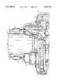
- FIG. 2is an elevational view, partially in section, of the apparatus
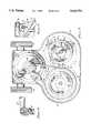
- FIG. 3is a horizontal sectional view taken generally as indicated by line 3--3 in FIG. 2;
- FIG. 4is an enlarged sectional view taken as indicated by line 4--4 in FIG. 3;
- FIG. 8is a diagrammatic depiction of a cleaning fluid system for an appliance utilizing a hydraulic motor to drive the cleaning heads.
- the numeral 11designates generally the surface cleaning appliance of this invention.
- the appliancecomprises a housing 12 mounted on wheels 13 for movement across the surface, such as a rug, to be cleaned.
- the applianceis manipulated by means of a handle 14 hingedly attached to the housing 12.
- Hoses 16 and 17are connected, respectively, to sources of cleaning fluid under pressure and a vacuum, neither of which are shown.
- sourcesmay, for example, comprise the system shown and described in the aforementioned Roden patent.
- each head 19comprises, in turn, a plurality of vacuum nozzles 21 and a plurality of spray nozzles 22.
- each rotating head 19includes three downwardly directed vacuum nozzles 21 which are adapted to contact the surface to be cleaned.
- the open lower end 23 of each vacuum nozzle 21extends generally radially of the axis of rotation of each head 19.
- the vacuum nozzles 21 of one head 19are angularly offset from the vacuum nozzles 21 of the other head. And, the path of travel of vacuum nozzles 21 on one head overlaps the path of travel of the nozzles 21 on the other head. As the heads 19 are rotated in opposite directions at the same speed, their respective vacuum nozzles 21 interdigitate and produce overlapping vacuum patterns. Note the nozzle overlap "0" indicated in FIG. 2.
- Synchronized rotation of the two heads 19is assured by intermeshing ring gears 24 mounted atop the vacuum nozzles 21 in each head. This prevents the vacuum nozzles 21 on one head from contacting the vacuum nozzles on the other head.
- Each head 19also includes three downwardly directed spray nozzles 22 which are interspersed between the vacuum nozzles 21 and positioned above the surface to be cleaned.
- the cleaning fluid spray nozzles 22 on each head 19are carried by and are in communication with a circular supply manifold 33. (See FIG. 4).
- the supply manifold on each head 19is mounted by means of brackets 34 which rest atop bosses 36 on the vacuum nozzles 21. (See FIGS. 3 and 4).
- Bolts 37 passing through slotted openings 38 in the brackets 36clamp the supply manifold 33 onto the vacuum nozzles 21.
- the slotted openings 38 in brackets 34permit the angular displacement of the spray nozzles 22 to be adjusted with respect to the vacuum nozzles 21. This is accomplished by loosening bolts 37 and rotating supply manifold 33 relative to the vacuum nozzles 21.
- the amount of angular displacement between a spray nozzle 22 and the trailing vacuum nozzle 21determines the time interval the cleaning fluid is permitted to remain in contact with the surface being cleaned before the cleaning fluid and debris are vacuumed away.
- Cleaning fluidis supplied to the spray nozzles 22 on each rotating head 19 from a fluid-tight coupling 39 positioned above each head.
- Each coupling 39is connected to a branch 40 of cleaning fluid hoses 16 and communicates with a rotatable pipe 41 carried by a bearing 42 in the upper end of cap 29.
- Pipe 41terminates at its lower end in a fitting 43 carried by the vacuum nozzles 21 for rotation therewith.
- Fitting 43communicates with a lateral pipe 44 which extends outwardly and upwardly to communicate with spray nozzle ring manifold 33.
- the rotation of heads 19 within housing 12can be imparted by any suitable means, such as an electric motor 45.
- the drive connection between motor 45 and the rotating heads 19is illustrated in FIG. 3.
- a gear reduction unit 51 beneath motor 46has an output pulley 52.
- a flexible V-belt 53transfers rotary motion from pulley 52 to a larger pulley 54 carried by one of the rotating heads 19.
- An idler pulley 56may be provided for maintaining tension in the belt 53.
- the other rotating head 19is, of course, driven from the belted head by the ring gears 24.
- This inventionmakes further provision for changing the relationship between the cleaning fluid spray pattern and the vacuum patterns produced by the rotating heads.
- the type of changes that can be affectedare illustrated in FIGS. 6 and 7.
- the annular patterns of vacuum produced by the rotating vacuum nozzles 21is relatively fixed by the design of the nozzles themselves. However, different sets of spray nozzles 22 can be substituted to change the width of the annular spray pattern produced by the rotating heads.
- the outer diameter of the spray patterndesignated with an “S”
- the outer diameter of the vacuum pattern "V"is caused to be smaller than the outer diameter of the vacuum pattern "V".
- the larger diameter vacuum patternprovides an annular outer ring for dry vacuuming the surface before it is sprayed. This can be advantageous when there is a great deal of loose, dry debris on the surface that might be more firmly affixed to the surface by the spray.
- FIG. 8illustrates diagrammatically the cleaning fluid flow system for an appliance employing a hydraulic motor 46 to drive the cleaning heads 19.
- Energy to propel the hydraulic motor 46is supplied by the pressurized cleaning fluid being conveyed to the cleaning heads 19.
- Cleaning fluid from hose 16is supplied to the motor 46 via an inlet pipe 47.
- Cleaning fluidexits the motor through an outlet pipe 48 which is connected to an inlet manifold 49 supplying cleaning fluid to the two fluid-tight couplings 39.
- this inventionprovides an improved surface cleaning appliance.
- the oppositely rotating cleaning headsprovide for stable operation and easy manipulation of the appliance.
- the overlapping spray and vacuum patterns producedassure a wide swath of cleaning surface with no gap between the heads.
- use of a hydraulic motor to drive the headsgreatly simplifies the appliance in contrast to electric motor driven appliances.
Landscapes
- Cleaning By Liquid Or Steam (AREA)
Abstract
Description
Claims (10)
Priority Applications (1)
| Application Number | Priority Date | Filing Date | Title |
|---|---|---|---|
| US08/299,276US5463791A (en) | 1994-09-01 | 1994-09-01 | Surface cleaning appliance |
Applications Claiming Priority (1)
| Application Number | Priority Date | Filing Date | Title |
|---|---|---|---|
| US08/299,276US5463791A (en) | 1994-09-01 | 1994-09-01 | Surface cleaning appliance |
Publications (1)
| Publication Number | Publication Date |
|---|---|
| US5463791Atrue US5463791A (en) | 1995-11-07 |
Family
ID=23154096
Family Applications (1)
| Application Number | Title | Priority Date | Filing Date |
|---|---|---|---|
| US08/299,276Expired - LifetimeUS5463791A (en) | 1994-09-01 | 1994-09-01 | Surface cleaning appliance |
Country Status (1)
| Country | Link |
|---|---|
| US (1) | US5463791A (en) |
Cited By (34)
| Publication number | Priority date | Publication date | Assignee | Title |
|---|---|---|---|---|
| US5784754A (en)* | 1997-06-13 | 1998-07-28 | Professional Chemicals Corporation | Surface cleaning appliance |
| US6032326A (en)* | 1998-11-06 | 2000-03-07 | Professional Chemicals Corporation | Surface cleaning appliance |
| US6151748A (en)* | 2000-03-21 | 2000-11-28 | Environmental Cleaning Systems, Inc. | Carpeting and surface cleaning apparatus |
| US6266892B1 (en) | 1999-07-19 | 2001-07-31 | Concept Cleaning Systems, Inc. | Device for enhancing removal of liquid from fabric |
| US6298577B1 (en) | 1999-07-19 | 2001-10-09 | Concept Cleaning Systems, Inc. | Device for enhancing removal of liquid from fabric |
| US6355112B1 (en) | 2000-08-04 | 2002-03-12 | Dri-Eaz Products, Inc. | Systems and methods for extracting liquid from floor coverings |
| WO2003073901A1 (en)* | 2002-02-28 | 2003-09-12 | William Dell | High efficiency vacuum cleaning apparatus and method |
| US6981338B2 (en) | 2003-12-23 | 2006-01-03 | Jensen Dale S | Device for improved removal of liquid from fabric |
| WO2007087200A3 (en)* | 2006-01-20 | 2008-05-02 | James P Shea | Material-removal system including a fluid-blasting, spray-head assembly |
| US20090050629A1 (en)* | 2007-08-17 | 2009-02-26 | High Impact Technology, Inc. | Sealing-reaction, layer-effective, stealth liner for synthetic fuel container |
| US20090169757A1 (en)* | 2005-05-03 | 2009-07-02 | High Impact Technology, L.L.C. | Barrier-coating layer application method |
| US20090239064A1 (en)* | 2008-03-12 | 2009-09-24 | Ohnstad Thomas S | Marine-vessell, Anti-puncture, self-sealing, water-leak protection |
| US20100285247A1 (en)* | 2008-07-22 | 2010-11-11 | High Impact Technology, L.L.C. | Combined self-sealing, and chemical and visual camouflage coating |
| US8061373B1 (en) | 2008-10-09 | 2011-11-22 | Storms John R | Surface cleaning apparatus |
| USD684737S1 (en) | 2011-08-31 | 2013-06-18 | Dri-Eaz Products, Inc. | Extractor housing |
| US8510902B2 (en) | 2007-12-03 | 2013-08-20 | Dri-Eaz Products, Inc. | Air induction hard surface cleaning tool with an internal baffle |
| USD701661S1 (en) | 2012-09-04 | 2014-03-25 | Dri-Eaz Products, Inc. | Extractor port housing |
| US20140173864A1 (en)* | 2012-12-20 | 2014-06-26 | Amano Pioneer Eclipse Corporation | Ultra high speed twin headed burnisher with pologanial pads and methods |
| US9072415B2 (en) | 2010-11-05 | 2015-07-07 | Bissell Homecare, Inc. | Bare floor vacuum cleaner |
| US9107557B2 (en) | 2011-03-14 | 2015-08-18 | Roy Studebaker | Rotary surface cleaning tool |
| US9195238B2 (en) | 2012-06-15 | 2015-11-24 | Sapphire Scientific, Inc. | Waste water vessels with multiple valved chambers, and associated systems and methods |
| US9351622B2 (en) | 2012-09-04 | 2016-05-31 | Sapphire Scientific Inc. | Fluid extracting device with shaped head and associated systems and methods of use and manufacture |
| US9370674B2 (en) | 2011-12-05 | 2016-06-21 | High Impact Technology, Llc | Plural layer, plural-action protective coating for liquid fuel container |
| US9402523B2 (en) | 2011-03-14 | 2016-08-02 | Roy Studebaker | Rotary surface cleaning tool |
| US20170311769A1 (en)* | 2016-04-30 | 2017-11-02 | Skagit Northwest Holdings, Inc. | Rotary surface cleaning tool |
| US10060641B2 (en) | 2015-02-25 | 2018-08-28 | Dri-Eaz Products, Inc. | Systems and methods for drying roofs |
| US10264939B2 (en) | 2015-08-17 | 2019-04-23 | Skagit Northwest Holdings, Inc. | Rotary surface cleaning tool |
| US10555657B2 (en) | 2003-05-14 | 2020-02-11 | Kärcher North America, Inc. | Floor treatment apparatus |
| US10584497B2 (en) | 2014-12-05 | 2020-03-10 | Dri-Eaz Products, Inc. | Roof cleaning processes and associated systems |
| US10646088B2 (en) | 2011-09-15 | 2020-05-12 | Harris Research, Inc. | Truck mounted cleaning system |
| USD907868S1 (en) | 2019-01-24 | 2021-01-12 | Karcher North America, Inc. | Floor cleaner |
| CN112587065A (en)* | 2020-12-07 | 2021-04-02 | 程代琴 | Portable children's safety seat cleaner |
| US20220298723A1 (en)* | 2019-08-27 | 2022-09-22 | 24 Pesula Oy | Washing unit, planar washing machine and method |
| US12070181B2 (en) | 2017-05-04 | 2024-08-27 | Alfred Kärcher SE & Co. KG | Floor cleaning appliance and method for cleaning a floor surface |
Citations (10)
| Publication number | Priority date | Publication date | Assignee | Title |
|---|---|---|---|---|
| US3619848A (en)* | 1968-10-09 | 1971-11-16 | Alfred M Salzmann | Appliance for cleaning floors |
| US3624668A (en)* | 1970-07-23 | 1971-11-30 | Helmuth W Krause | Rug cleaning and rinsing device |
| US4182001A (en)* | 1973-03-15 | 1980-01-08 | Krause Helmuth W | Surface cleaning and rinsing device |
| US4264999A (en)* | 1979-10-30 | 1981-05-05 | Monson Clifford L | Rotary flooring surface treating device |
| US4333204A (en)* | 1979-10-30 | 1982-06-08 | Monson Clifford L | Rotary flooring surface treating device |
| US4339840A (en)* | 1979-10-30 | 1982-07-20 | Monson Clifford L | Rotary flooring surface treating device |
| US4441229A (en)* | 1981-04-06 | 1984-04-10 | Monson Clifford L | Rotary cleaner-polisher |
| US4692959A (en)* | 1986-03-11 | 1987-09-15 | Monson Clifford L | Rotary cleaner/scrubber mechanism |
| US4991254A (en)* | 1988-12-19 | 1991-02-12 | Professional Chemicals Corporation | Cleaning system |
| US5321869A (en)* | 1990-07-12 | 1994-06-21 | Deutsche Lufthansa Ag | Device for removing paint from painted surfaces |
- 1994
- 1994-09-01USUS08/299,276patent/US5463791A/ennot_activeExpired - Lifetime
Patent Citations (10)
| Publication number | Priority date | Publication date | Assignee | Title |
|---|---|---|---|---|
| US3619848A (en)* | 1968-10-09 | 1971-11-16 | Alfred M Salzmann | Appliance for cleaning floors |
| US3624668A (en)* | 1970-07-23 | 1971-11-30 | Helmuth W Krause | Rug cleaning and rinsing device |
| US4182001A (en)* | 1973-03-15 | 1980-01-08 | Krause Helmuth W | Surface cleaning and rinsing device |
| US4264999A (en)* | 1979-10-30 | 1981-05-05 | Monson Clifford L | Rotary flooring surface treating device |
| US4333204A (en)* | 1979-10-30 | 1982-06-08 | Monson Clifford L | Rotary flooring surface treating device |
| US4339840A (en)* | 1979-10-30 | 1982-07-20 | Monson Clifford L | Rotary flooring surface treating device |
| US4441229A (en)* | 1981-04-06 | 1984-04-10 | Monson Clifford L | Rotary cleaner-polisher |
| US4692959A (en)* | 1986-03-11 | 1987-09-15 | Monson Clifford L | Rotary cleaner/scrubber mechanism |
| US4991254A (en)* | 1988-12-19 | 1991-02-12 | Professional Chemicals Corporation | Cleaning system |
| US5321869A (en)* | 1990-07-12 | 1994-06-21 | Deutsche Lufthansa Ag | Device for removing paint from painted surfaces |
Cited By (45)
| Publication number | Priority date | Publication date | Assignee | Title |
|---|---|---|---|---|
| US5784754A (en)* | 1997-06-13 | 1998-07-28 | Professional Chemicals Corporation | Surface cleaning appliance |
| US6032326A (en)* | 1998-11-06 | 2000-03-07 | Professional Chemicals Corporation | Surface cleaning appliance |
| US6266892B1 (en) | 1999-07-19 | 2001-07-31 | Concept Cleaning Systems, Inc. | Device for enhancing removal of liquid from fabric |
| US6298577B1 (en) | 1999-07-19 | 2001-10-09 | Concept Cleaning Systems, Inc. | Device for enhancing removal of liquid from fabric |
| US6151748A (en)* | 2000-03-21 | 2000-11-28 | Environmental Cleaning Systems, Inc. | Carpeting and surface cleaning apparatus |
| US6355112B1 (en) | 2000-08-04 | 2002-03-12 | Dri-Eaz Products, Inc. | Systems and methods for extracting liquid from floor coverings |
| WO2003073901A1 (en)* | 2002-02-28 | 2003-09-12 | William Dell | High efficiency vacuum cleaning apparatus and method |
| US6643894B1 (en) | 2002-02-28 | 2003-11-11 | William C. Dell | High efficiency vacuum cleaning apparatus and method |
| US10555657B2 (en) | 2003-05-14 | 2020-02-11 | Kärcher North America, Inc. | Floor treatment apparatus |
| US6981338B2 (en) | 2003-12-23 | 2006-01-03 | Jensen Dale S | Device for improved removal of liquid from fabric |
| US20090169757A1 (en)* | 2005-05-03 | 2009-07-02 | High Impact Technology, L.L.C. | Barrier-coating layer application method |
| US8389063B2 (en)* | 2005-05-03 | 2013-03-05 | High Impact Technology, Inc. | Barrier-coating layer application method |
| WO2007087200A3 (en)* | 2006-01-20 | 2008-05-02 | James P Shea | Material-removal system including a fluid-blasting, spray-head assembly |
| US20090050629A1 (en)* | 2007-08-17 | 2009-02-26 | High Impact Technology, Inc. | Sealing-reaction, layer-effective, stealth liner for synthetic fuel container |
| US8043676B2 (en) | 2007-08-17 | 2011-10-25 | High Impact Technology, L.L.C. | Sealing-reaction, layer-effective, stealth liner for synthetic fuel container |
| US9066647B2 (en) | 2007-12-03 | 2015-06-30 | Dri-Eaz Products, Inc. | Air induction hard surface cleaning tools with an internal baffle |
| US8510902B2 (en) | 2007-12-03 | 2013-08-20 | Dri-Eaz Products, Inc. | Air induction hard surface cleaning tool with an internal baffle |
| US8387548B2 (en) | 2008-03-12 | 2013-03-05 | High Impact Technology, Inc. | Marine-vessel, anti-puncture, self-sealing, water-leak protection |
| US20090239064A1 (en)* | 2008-03-12 | 2009-09-24 | Ohnstad Thomas S | Marine-vessell, Anti-puncture, self-sealing, water-leak protection |
| US20100285247A1 (en)* | 2008-07-22 | 2010-11-11 | High Impact Technology, L.L.C. | Combined self-sealing, and chemical and visual camouflage coating |
| US8061373B1 (en) | 2008-10-09 | 2011-11-22 | Storms John R | Surface cleaning apparatus |
| US9706888B2 (en) | 2010-11-05 | 2017-07-18 | Bissell Homecare, Inc. | Bare floor vacuum cleaner |
| US9993127B2 (en) | 2010-11-05 | 2018-06-12 | Bissell Homecare, Inc. | Vacuum cleaner |
| US9072415B2 (en) | 2010-11-05 | 2015-07-07 | Bissell Homecare, Inc. | Bare floor vacuum cleaner |
| US10820764B2 (en) | 2010-11-05 | 2020-11-03 | Bissell Inc. | Vacuum cleaner |
| US11903550B2 (en) | 2010-11-05 | 2024-02-20 | Bissell Inc. | Vacuum cleaner |
| US9107557B2 (en) | 2011-03-14 | 2015-08-18 | Roy Studebaker | Rotary surface cleaning tool |
| US9402523B2 (en) | 2011-03-14 | 2016-08-02 | Roy Studebaker | Rotary surface cleaning tool |
| USD684737S1 (en) | 2011-08-31 | 2013-06-18 | Dri-Eaz Products, Inc. | Extractor housing |
| US10646088B2 (en) | 2011-09-15 | 2020-05-12 | Harris Research, Inc. | Truck mounted cleaning system |
| US9370674B2 (en) | 2011-12-05 | 2016-06-21 | High Impact Technology, Llc | Plural layer, plural-action protective coating for liquid fuel container |
| US9195238B2 (en) | 2012-06-15 | 2015-11-24 | Sapphire Scientific, Inc. | Waste water vessels with multiple valved chambers, and associated systems and methods |
| US9351622B2 (en) | 2012-09-04 | 2016-05-31 | Sapphire Scientific Inc. | Fluid extracting device with shaped head and associated systems and methods of use and manufacture |
| USD701661S1 (en) | 2012-09-04 | 2014-03-25 | Dri-Eaz Products, Inc. | Extractor port housing |
| US20140173864A1 (en)* | 2012-12-20 | 2014-06-26 | Amano Pioneer Eclipse Corporation | Ultra high speed twin headed burnisher with pologanial pads and methods |
| US10584497B2 (en) | 2014-12-05 | 2020-03-10 | Dri-Eaz Products, Inc. | Roof cleaning processes and associated systems |
| US10753628B2 (en) | 2015-02-25 | 2020-08-25 | Legend Brands, Inc. | Systems and methods for drying roofs |
| US10060641B2 (en) | 2015-02-25 | 2018-08-28 | Dri-Eaz Products, Inc. | Systems and methods for drying roofs |
| US11686482B2 (en) | 2015-02-25 | 2023-06-27 | Legend Brands, Inc. | Systems and methods for drying roofs |
| US10264939B2 (en) | 2015-08-17 | 2019-04-23 | Skagit Northwest Holdings, Inc. | Rotary surface cleaning tool |
| US20170311769A1 (en)* | 2016-04-30 | 2017-11-02 | Skagit Northwest Holdings, Inc. | Rotary surface cleaning tool |
| US12070181B2 (en) | 2017-05-04 | 2024-08-27 | Alfred Kärcher SE & Co. KG | Floor cleaning appliance and method for cleaning a floor surface |
| USD907868S1 (en) | 2019-01-24 | 2021-01-12 | Karcher North America, Inc. | Floor cleaner |
| US20220298723A1 (en)* | 2019-08-27 | 2022-09-22 | 24 Pesula Oy | Washing unit, planar washing machine and method |
| CN112587065A (en)* | 2020-12-07 | 2021-04-02 | 程代琴 | Portable children's safety seat cleaner |
Similar Documents
| Publication | Publication Date | Title |
|---|---|---|
| US5463791A (en) | Surface cleaning appliance | |
| USRE37162E1 (en) | Hard surface cleaning appliance | |
| US6032326A (en) | Surface cleaning appliance | |
| US6151748A (en) | Carpeting and surface cleaning apparatus | |
| US5293665A (en) | Nozzle mechanism for a vacuum cleaner | |
| US6260232B1 (en) | Surface cleaning apparatus | |
| US4461052A (en) | Scrubbing brush, rinse and sweeping equipment | |
| US8118241B2 (en) | Surface cleaner system | |
| CA1205609A (en) | Rotary flooring surface treating device | |
| US4182001A (en) | Surface cleaning and rinsing device | |
| JP4913078B2 (en) | Apparatus and method for cleaning fabrics, floor coverings and bare floor surfaces using a soil transfer cleaning medium | |
| US5891198A (en) | Fabric cleaning method and system | |
| US9295366B2 (en) | Rotary cleaning head having indirect fluid application | |
| US4488329A (en) | Power spray nozzle with fluidic oscillator | |
| US5077862A (en) | Carpet cleaning machine with edge-mounted vacuum nozzle | |
| TWI888072B (en) | Mop, nozzle, and cleaner | |
| US20110030724A1 (en) | Multifunction Pressure Washer | |
| EP0463035B1 (en) | A machine for treating floor surfaces | |
| US4939808A (en) | Carpet cleaning apparatus | |
| US3314099A (en) | Floor cleaning apparatus | |
| CN110080141A (en) | A kind of cleaning equipment for road stake | |
| CN213524978U (en) | Surface cleaning apparatus | |
| CA1319475C (en) | Cleaning device | |
| KR102589255B1 (en) | Textile pre-processing device | |
| WO2025015608A1 (en) | Extraction cleaner |
Legal Events
| Date | Code | Title | Description |
|---|---|---|---|
| AS | Assignment | Owner name:REDFIELD ENGINEERING, ARIZONA Free format text:ASSIGNMENT OF ASSIGNORS INTEREST;ASSIGNOR:RODEN, MICHAEL J.;REEL/FRAME:007245/0012 Effective date:19940804 | |
| STCF | Information on status: patent grant | Free format text:PATENTED CASE | |
| FEPP | Fee payment procedure | Free format text:PAYOR NUMBER ASSIGNED (ORIGINAL EVENT CODE: ASPN); ENTITY STATUS OF PATENT OWNER: LARGE ENTITY | |
| AS | Assignment | Owner name:PROFESSIONAL CHEMICALS CORPORATION, ARIZONA Free format text:ASSIGNMENT OF ASSIGNORS INTEREST;ASSIGNOR:REDFIELD ENGINEERING;REEL/FRAME:009866/0394 Effective date:19990315 | |
| FPAY | Fee payment | Year of fee payment:4 | |
| AS | Assignment | Owner name:FLEET NATIONAL BANK, AS AGENT, MASSACHUSETTS Free format text:SECURITY INTEREST;ASSIGNOR:PROFESSIONAL CHEMICALS CORPORATION;REEL/FRAME:012865/0502 Effective date:20020328 | |
| FEPP | Fee payment procedure | Free format text:PAT HOLDER NO LONGER CLAIMS SMALL ENTITY STATUS, ENTITY STATUS SET TO UNDISCOUNTED (ORIGINAL EVENT CODE: STOL); ENTITY STATUS OF PATENT OWNER: LARGE ENTITY | |
| REFU | Refund | Free format text:REFUND - PAYMENT OF MAINTENANCE FEE, 8TH YR, SMALL ENTITY (ORIGINAL EVENT CODE: R2552); ENTITY STATUS OF PATENT OWNER: LARGE ENTITY Free format text:REFUND - 7.5 YR SURCHARGE - LATE PMT W/IN 6 MO, SMALL ENTITY (ORIGINAL EVENT CODE: R2555); ENTITY STATUS OF PATENT OWNER: LARGE ENTITY | |
| REMI | Maintenance fee reminder mailed | ||
| AS | Assignment | Owner name:FLEET NATIONAL BANK, MASSACHUSETTS Free format text:SECURITY AGREEMENT;ASSIGNOR:PROFESSIONAL CHEMICALS CORPORATION;REEL/FRAME:014428/0865 Effective date:20000418 | |
| FPAY | Fee payment | Year of fee payment:8 | |
| SULP | Surcharge for late payment | Year of fee payment:7 | |
| AS | Assignment | Owner name:CASTLE ROCK INDUSTRIES, INC., COLORADO Free format text:ASSIGNMENT OF ASSIGNORS INTEREST;ASSIGNOR:PROFESSIONAL CHEMICALS CORPORATION;REEL/FRAME:015293/0159 Effective date:20040412 | |
| AS | Assignment | Owner name:HARRIS TRUST AND SAVINGS BANK, AS ADMINISTRATIVE A Free format text:SECURITY AGREEMENT;ASSIGNOR:PROFESSIONAL CHEMICALS CORPORATION;REEL/FRAME:015509/0283 Effective date:20040602 | |
| AS | Assignment | Owner name:PROFESSIONAL CHEMICALS CORPORATION, COLORADO Free format text:RELEASE BY SECURED PARTY;ASSIGNOR:FLEET NATIONAL BANK, AS AGENT;REEL/FRAME:015541/0286 Effective date:20040614 | |
| FPAY | Fee payment | Year of fee payment:12 | |
| AS | Assignment | Owner name:KARCHER FLOOR CARE, INC., COLORADO Free format text:CHANGE OF NAME;ASSIGNOR:CASTLE ROCK INDUSTRIES, INC.;REEL/FRAME:019795/0132 Effective date:20070419 | |
| AS | Assignment | Owner name:KARCHER NORTH AMERICA, INC., COLORADO Free format text:MERGER;ASSIGNORS:KARCHER FLOOR CARE, INC.;KARCHER RESIDENTIAL SOLUTIONS, INC.;REEL/FRAME:022390/0283 Effective date:20081231 | |
| AS | Assignment | Owner name:PROFESSIONAL CHEMICALS CORPORATION, COLORADO Free format text:RELEASE BY SECURED PARTY;ASSIGNOR:BMO HARRIS BANK N.A., SUCCESSOR TO HARRIS TRUST AND SAVINGS BANK;REEL/FRAME:041688/0188 Effective date:20170322 |