US5463692A - Sandwich switch construction for a hearing aid - Google Patents
Sandwich switch construction for a hearing aidDownload PDFInfo
- Publication number
- US5463692A US5463692AUS08/273,200US27320094AUS5463692AUS 5463692 AUS5463692 AUS 5463692AUS 27320094 AUS27320094 AUS 27320094AUS 5463692 AUS5463692 AUS 5463692A
- Authority
- US
- United States
- Prior art keywords
- sandwich
- electrical lead
- elastomeric membrane
- upper housing
- base surface
- Prior art date
- Legal status (The legal status is an assumption and is not a legal conclusion. Google has not performed a legal analysis and makes no representation as to the accuracy of the status listed.)
- Expired - Fee Related
Links
- 238000010276constructionMethods0.000titleclaimsabstractdescription20
- 239000012528membraneSubstances0.000claimsabstractdescription44
- 238000004891communicationMethods0.000claimsabstractdescription20
- 235000012489doughnutsNutrition0.000claimsdescription6
- 239000006260foamSubstances0.000claimsdescription6
- 230000006870functionEffects0.000claimsdescription5
- 238000004519manufacturing processMethods0.000claimsdescription3
- 230000004913activationEffects0.000description4
- 229920001971elastomerPolymers0.000description4
- 238000001914filtrationMethods0.000description4
- 239000000463materialSubstances0.000description4
- 239000005060rubberSubstances0.000description4
- 230000003213activating effectEffects0.000description3
- 239000003522acrylic cementSubstances0.000description2
- 238000000465mouldingMethods0.000description2
- 239000004033plasticSubstances0.000description2
- 239000003795chemical substances by applicationSubstances0.000description1
- 239000000356contaminantSubstances0.000description1
- 230000002542deteriorative effectEffects0.000description1
- 239000000428dustSubstances0.000description1
- 230000007257malfunctionEffects0.000description1
- 229940074869marquisDrugs0.000description1
- 239000003921oilSubstances0.000description1
- 238000007747platingMethods0.000description1
- 229920000728polyesterPolymers0.000description1
- 229920006267polyester filmPolymers0.000description1
- VBUNOIXRZNJNAD-UHFFFAOYSA-NponazurilChemical compoundCC1=CC(N2C(N(C)C(=O)NC2=O)=O)=CC=C1OC1=CC=C(S(=O)(=O)C(F)(F)F)C=C1VBUNOIXRZNJNAD-UHFFFAOYSA-N0.000description1
- 238000012216screeningMethods0.000description1
- 238000007789sealingMethods0.000description1
- 229910052710siliconInorganic materials0.000description1
- 239000010703siliconSubstances0.000description1
- 210000004243sweatAnatomy0.000description1
- XLYOFNOQVPJJNP-UHFFFAOYSA-NwaterSubstancesOXLYOFNOQVPJJNP-UHFFFAOYSA-N0.000description1
- 238000003466weldingMethods0.000description1
Images


Classifications
- H—ELECTRICITY
- H01—ELECTRIC ELEMENTS
- H01H—ELECTRIC SWITCHES; RELAYS; SELECTORS; EMERGENCY PROTECTIVE DEVICES
- H01H19/00—Switches operated by an operating part which is rotatable about a longitudinal axis thereof and which is acted upon directly by a solid body external to the switch, e.g. by a hand
- H01H19/54—Switches operated by an operating part which is rotatable about a longitudinal axis thereof and which is acted upon directly by a solid body external to the switch, e.g. by a hand the operating part having at least five or an unspecified number of operative positions
- H01H19/60—Angularly-movable actuating part carrying no contacts
- H01H19/63—Contacts actuated by axial cams
- H—ELECTRICITY
- H04—ELECTRIC COMMUNICATION TECHNIQUE
- H04R—LOUDSPEAKERS, MICROPHONES, GRAMOPHONE PICK-UPS OR LIKE ACOUSTIC ELECTROMECHANICAL TRANSDUCERS; DEAF-AID SETS; PUBLIC ADDRESS SYSTEMS
- H04R25/00—Deaf-aid sets, i.e. electro-acoustic or electro-mechanical hearing aids; Electric tinnitus maskers providing an auditory perception
- H04R25/65—Housing parts, e.g. shells, tips or moulds, or their manufacture
- H—ELECTRICITY
- H01—ELECTRIC ELEMENTS
- H01H—ELECTRIC SWITCHES; RELAYS; SELECTORS; EMERGENCY PROTECTIVE DEVICES
- H01H13/00—Switches having rectilinearly-movable operating part or parts adapted for pushing or pulling in one direction only, e.g. push-button switch
- H01H13/70—Switches having rectilinearly-movable operating part or parts adapted for pushing or pulling in one direction only, e.g. push-button switch having a plurality of operating members associated with different sets of contacts, e.g. keyboard
- H01H13/702—Switches having rectilinearly-movable operating part or parts adapted for pushing or pulling in one direction only, e.g. push-button switch having a plurality of operating members associated with different sets of contacts, e.g. keyboard with contacts carried by or formed from layers in a multilayer structure, e.g. membrane switches
- H—ELECTRICITY
- H01—ELECTRIC ELEMENTS
- H01H—ELECTRIC SWITCHES; RELAYS; SELECTORS; EMERGENCY PROTECTIVE DEVICES
- H01H15/00—Switches having rectilinearly-movable operating part or parts adapted for actuation in opposite directions, e.g. slide switch
- H01H15/02—Details
- H01H15/06—Movable parts; Contacts mounted thereon
- H01H15/10—Operating parts
- H01H15/102—Operating parts comprising cam devices
- H—ELECTRICITY
- H01—ELECTRIC ELEMENTS
- H01H—ELECTRIC SWITCHES; RELAYS; SELECTORS; EMERGENCY PROTECTIVE DEVICES
- H01H2221/00—Actuators
- H01H2221/008—Actuators other then push button
- H01H2221/01—Actuators other then push button also rotatable
- H—ELECTRICITY
- H01—ELECTRIC ELEMENTS
- H01H—ELECTRIC SWITCHES; RELAYS; SELECTORS; EMERGENCY PROTECTIVE DEVICES
- H01H2221/00—Actuators
- H01H2221/008—Actuators other then push button
- H01H2221/014—Slide selector
- H—ELECTRICITY
- H01—ELECTRIC ELEMENTS
- H01H—ELECTRIC SWITCHES; RELAYS; SELECTORS; EMERGENCY PROTECTIVE DEVICES
- H01H2221/00—Actuators
- H01H2221/008—Actuators other then push button
- H01H2221/016—Lever; Rocker
- H—ELECTRICITY
- H01—ELECTRIC ELEMENTS
- H01H—ELECTRIC SWITCHES; RELAYS; SELECTORS; EMERGENCY PROTECTIVE DEVICES
- H01H2221/00—Actuators
- H01H2221/008—Actuators other then push button
- H01H2221/018—Tumbler
- H—ELECTRICITY
- H01—ELECTRIC ELEMENTS
- H01H—ELECTRIC SWITCHES; RELAYS; SELECTORS; EMERGENCY PROTECTIVE DEVICES
- H01H2300/00—Orthogonal indexing scheme relating to electric switches, relays, selectors or emergency protective devices covered by H01H
- H01H2300/004—Application hearing aid
- H—ELECTRICITY
- H04—ELECTRIC COMMUNICATION TECHNIQUE
- H04R—LOUDSPEAKERS, MICROPHONES, GRAMOPHONE PICK-UPS OR LIKE ACOUSTIC ELECTROMECHANICAL TRANSDUCERS; DEAF-AID SETS; PUBLIC ADDRESS SYSTEMS
- H04R2225/00—Details of deaf aids covered by H04R25/00, not provided for in any of its subgroups
- H04R2225/61—Aspects relating to mechanical or electronic switches or control elements, e.g. functioning
- H—ELECTRICITY
- H04—ELECTRIC COMMUNICATION TECHNIQUE
- H04R—LOUDSPEAKERS, MICROPHONES, GRAMOPHONE PICK-UPS OR LIKE ACOUSTIC ELECTROMECHANICAL TRANSDUCERS; DEAF-AID SETS; PUBLIC ADDRESS SYSTEMS
- H04R25/00—Deaf-aid sets, i.e. electro-acoustic or electro-mechanical hearing aids; Electric tinnitus maskers providing an auditory perception
- H04R25/60—Mounting or interconnection of hearing aid parts, e.g. inside tips, housings or to ossicles
- H04R25/603—Mounting or interconnection of hearing aid parts, e.g. inside tips, housings or to ossicles of mechanical or electronic switches or control elements
- H—ELECTRICITY
- H04—ELECTRIC COMMUNICATION TECHNIQUE
- H04R—LOUDSPEAKERS, MICROPHONES, GRAMOPHONE PICK-UPS OR LIKE ACOUSTIC ELECTROMECHANICAL TRANSDUCERS; DEAF-AID SETS; PUBLIC ADDRESS SYSTEMS
- H04R25/00—Deaf-aid sets, i.e. electro-acoustic or electro-mechanical hearing aids; Electric tinnitus maskers providing an auditory perception
- H04R25/60—Mounting or interconnection of hearing aid parts, e.g. inside tips, housings or to ossicles
- H04R25/607—Mounting or interconnection of hearing aid parts, e.g. inside tips, housings or to ossicles of earhooks
Definitions
- the present inventionrelates generally to hearing aids, and more particularly, to hearing aids having a sandwich type switch construction with a deformable elastomeric membrane.
- Hearing aidsrequire switches which are used for a variety of purposes including on/off control, volume control, trimmer applications such as noise filtration control, and telecoil control such as a telephone receiver mode, etc.
- Hearing aid switches for both in-the-ear hearing aids and behind-the-ear hearing aidsmust be miniature to fit within the small space requirements of the hearing aid housings and to maintain the aesthetic qualities of hearing aids.
- wiper switches used in hearing aidsinclude a wiper having a first end electrically and pivotally coupled to circuitry and a second or contact end which is wiped across either a nonconductive surface to open the switch or across a conductive surface to close the switch.
- the wiper switchis constructed to wipe across a variable resistance path if the wiper switch is to used for volume control or noise filtration.
- wiper switcheshave several drawbacks. Since the voltage through hearing aid circuits is low, wiper switches require precise fabrication to ensure electrical contact and to avoid generating electrical noise. Precise fabrication is costly and requires the use of miniature parts which are difficult to handle and which tend to wear out and cause the switch to malfunction.
- a push button switchis disclosed in U.S. Pat. No. 4,634,815 to Marquis for turning the hearing aid on and off and for volume control.
- the switchis activated by rotating the button such that a contact tongue contacts a contact member to close a circuit.
- the push buttonis pressed causing a diaphragm to depress and close another circuit.
- Volume controlis either limited to two settings or is changed in proportion to the time period for which contact is maintained.
- the present inventionrelates to a sandwich switch construction for a hearing aid which includes a lower housing having a base surface or a rigid circuit board or flexible circuit with a first electrical lead defined thereon, and an elastomeric membrane with a second electrical lead formed thereon in alignment with the first electrical lead. A portion of the elastomeric membrane is spaced apart from the base surface such that the first electrical lead is not in electrical communication with the second electrical lead wherein the sandwich switch is open.
- An upper housing operable with the lower housinghas contact means associated therewith operable between a first position wherein the elastomeric membrane is deformed toward the base surface such that the first electrical lead is in electrical communication with the second electrical lead wherein the sandwich switch is closed, and a second position wherein the elastomeric membrane is deformed away from the base surface wherein the sandwich switch is open.
- the upper housingis rotatably mounted to the lower housing
- the contact mechanismincludes a cam fixedly mounted to the upper housing such that rotation of the upper housing causes the cam to contact and compress the spaced apart portion of the elastomeric membrane such that the first and second leads are in electrical communication.
- the contact mechanismincludes a toggle pivotally mounted within the upper housing for moving the first and second leads into and out of communication with each other.
- the togglepivots in a first direction such that the toggle contacts and compresses the spaced apart portion of the elastomeric membrane such that the first and second leads are in communication with each other and in a second direction such that the toggle is not in contact with the spaced apart portion of the elastomeric membrane such that the spaced apart portion of the elastomeric membrane deforms back to its original position such that the first and second leads are not in communication with each other.
- the contact mechanismincludes a slide slidably mounted within a track in the upper housing for moving the first and second leads into and out of communication with each other.
- the slideis slidable within the track in a first direction such that the slide contacts and compresses the spaced apart portion of the elastomeric membrane such that the first and second leads are in communication with each other and in a second direction such that the slide is not in communication with the spaced apart portion of the elastomeric membrane such that the spaced apart portion of the elastomeric membrane deforms back to its original position such that the first and second leads are not in communication with each other.
- contact mechanismis in the form of a push button switch, a momentary switch or a side wall switch.
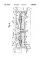
- FIG. 1is a side elevational view of a hearing aid having a three-position switch and a volume control switch made according to the present invention
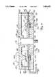
- FIG. 2is a sectional view of a sandwich switch made according to the present invention.
- FIG. 3is a diagrammatic plan view of a stator layer of the three-position switch made according to the present invention.
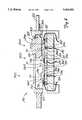
- FIG. 4is a sectional view of the three-position switch as seen from line 4--4 in FIG. 3;
- FIG. 5is a top plan view of a rotor layer of the three-position switch in position 1 made according to the present invention.
- FIG. 6is a diagrammatic plan view of a stator layer of a volume control
- FIG. 7is a sectional view of the volume control as seen from line 7--7 in FIG. 6;
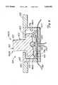
- FIG. 8is a sectional view of a second embodiment of the switch made according to the present invention.
- FIG. 9is a sectional view of a third embodiment of a switch made according to the present invention.
- a hearing aid illustrated generally at 10 in FIG. 1,includes a housing 12, containing electrical processing components such as a microphone, receiver, amplifier and speaker (not shown) for processing acoustic signals.
- a three-position switch 14is mounted to the housing 12 for switching between various hearing aid functions such as noise filtration and telephone receiver mode.
- An on/off, volume control switch 16is also mounted to the housing 12 for adjusting the volume of the acoustic signals and turning the hearing aid 10 on and off.
- a carrying hook 18 connected to the housing 12hangs the hearing aid 10 from an ear of a person wearing the hearing aid 10.
- a hose 20 secured to the carrying hook 18transmits the processed acoustic signals from the carrying hook 18 to an ear adaptor 22.
- the ear adapter 22fits in the auditory canal of the person using the hearing aid for transmitting acoustic sounds from the hose 20 to the person.
- the housing 12, the carrying hook 18, the hose 20, and the ear adapter 22are well known components and are constructed in a conventional manner known to persons skilled in the art.
- a behind-the-ear hearing aid 10is illustrated, it is to be understood that the present invention may be used with an in-the-ear hearing aid as well.
- the sandwich switch 40includes a base layer 42, an elastomeric membrane 44 mounted to the base layer 42 such that a portion of the elastomeric membrane 44 is spaced apart from the base layer 42 to form a tactile dome 46 having a gap 48, and a contact mechanism 50 for deforming the tactile dome 46 of the table elastomeric membrane 44 towards the base layer 42 to activate and deactivate the sandwich switch 40.
- a conductive inkis screened, plated or molded (conductive rubber) into an upper surface 52 of the base layer 42 to form a first lead 54 and a first contact 56, and also onto a lower surface 57 of the elastomeric membrane 44 to form a second lead 58 and a second contact 64.
- the first contact 56 and the second contact 64are formed under the tactile dome 46 in the gap 48 between the base layer 42 and the elastomeric membrane 44 and are aligned with each other such that when the contact mechanism 50 deforms the elastomeric membrane 44 the first and second contacts 56 and 64 are put into communication with each other to activate the sandwich switch 40.
- the tactile domes 46completely seal off the first and second contacts 56 and 59 such that water, sweat, moisture, dust, oils, and other contaminants are kept away from the sandwich switch 40 thereby increasing the reliability of the switch.
- the first and second leads 54 and 58are connected to circuitry (not shown) for performing various functions such as volume control, noise reduction, telephone mode, etc.
- the base layer 42may be an elastomeric membrane or plastic material with leads formed thereon, or of a rigid circuit board or flexible circuit construction with defined electrical traces and contacts thereon. Of course, the construction of the electrical leads and traces will differ depending on whether an elastomeric membrane, rigid circuit board or flexible circuit construction is used for forming the sandwich switches thereon.
- the sandwich switch 40may be constructed, for example, by screening, plating or molding a conductive ink path on both the upper surface 52 of the base layer 42 and on the lower surface 51 of the elastomeric membrane 44 to form the first and second leads 54 and 58 and the first and second contacts 56 and 59.
- the conductive inkis well known to those skilled in the art.
- the elastomeric membrane 44maybe constructed of a thin polyester film, or any type of flexible material such as molded silicon, conductive rubbers, or grafite filets. If constructed of polyester, the elastomeric layer is approximately 0.003"-0.020" thick, although the thickness will vary depending on the material used. Depending on the material used for the elastomeric membrane 44, the thickness is reduced at the tactile dome 46 to facilitate the deformation of the elastomeric membrane 44 to close the switch.
- the lower surface 57 of the upper elastomeric layer 44is sealed to the upper surface 52 of the base layer 42 by heat staking, cold slug staking, ultra sonic welding, double molding, etc.
- Insulative layersmay be screened over the conductive ink with openings for the first and second contacts 56 and 59, but are not necessary if the first and second leads 54 and 58 are oriented so as not to interfere with each other to short circuit the sandwich switch 40.
- the sandwich switch 40 construction of the present inventionwill now be described with respect to the three-position switch 14 and the volume control switch 16. It is to be understood that the present invention is not limited to use in a particular type of switch and that the number of, arrangement of, an attached circuitry to the sandwich switches 40 will vary depending on the type of switch in which the sandwich switches 40 are being used. The general structure and principles of operation of the sandwich switch 40 is the same regardless of the type or shape of switch. It is also to be understood that the sandwich switch 40 construction is not limited to hearing aid uses, since it can be used in any environment where it is desirable to provide a miniature switch which does require handling the miniature components to construct or operate the switch.
- the three-position switch 14includes a disc-shaped stator layer 60 fixedly mounted to the housing 12, a disc-shaped rotor layer 62 rotatably mounted to the stator layer 60, a plurality of sandwich switches 66A-66F formed on the stator layer 60 adjacent the rotor layer 62, and a plurality of cams 68A-68C mounted on the rotor layer 62 for engaging and disengaging the sandwich switches 66A-66F upon rotation of the rotor layer 62.
- a shoulder screw 72 and a nut 74operate with a hole in the stator and rotor layers 60 and 62 for securing the switch 14 to the housing 12.
- the three position switch 14is preferably less than or equal to 0.400 inches in diameter and less than or equal to 0.300 inches in thickness and is used to switch between three hearing aid functions such as telephone mode, noise filtration mode and on/off mode, etc.
- two sandwich switches 66A and 66Bare constructed in one half of the stator layer 60 and four sandwich switches 66C-66F are constructed in the other half of the stator layer 60.
- Sandwich switch 66A-66Bare associated with circuitry units 78A and 78B, respectfully, for performing hearing aid functions and are single activation switches meaning that each circuit 78A and 78B is closed when the respective sandwich switch 66A, 66B is activated.
- Sandwich switches 68C-68Fare associated with circuitry units 78C and 78D and are arranged in pairs and connected in series within each pair to form double activation switches meaning that each circuit 78C and 78D is closed only when the respective pair of sandwich switches 68C-68D, and 68E-68F is activated.
- the lower lead of each sandwich switch 66A-66Fruns towards the center of the stator layer 60 either for connection to circuity within the hearing aid or for connection to one of the other sandwich switch leads to form a double activation switch.
- each sandwich switch 66A-66Fruns through a U-shaped lead connector 80A-80F positioned on the periphery of the stator layer 60 for connecting the sandwich switches 68A-68F to circuitry units 78A-78D within the hearing aid 10.
- the connectors 80A-80Faid in mounting the stator layer 60 to the housing 12 since each lead connector 80A-80F is engagable with a corresponding slot 81 in the housing 12. It should be apparent to those skilled in the art that termination of the leads could be through a socketed device and does not have to be hard wired as shown.
- each sandwich switch 66A-66Fincludes a lower elastomeric layer 90 having a plurality of lower leads 92A-92F and lower contacts 94 screened thereon, an upper elastomeric layer 96 having a plurality of upper leads 98A-98F and upper contacts 100 screened thereon corresponding to the lower leads 92A-92F and lower contacts 94 on the lower elastomeric layer 90, a travel spring 104 and a foam donut or O-ring 106.
- the lower elastomeric layer 90is mounted to a stator base 102 such that portions of the lower elastomeric layer 90 are spaced apart from the stator base 102 forming a plurality of first gaps 108A-108F below the lower contacts 94 of each sandwich switch 66A-66F.
- the travel spring 104 and the foam donut 106are positioned in each of the plurality of first gaps 108A-108F for supporting the lower elastomeric layer 90 and for providing a resilient force for returning the lower elastomeric layer 90 to its original position as it may be deformed when the sandwich switch 66A-66F is closed.
- the foam donut or O-ring 106may take of any form provided the resilient return force is generated.
- the upper elastomeric layer 96is mounted to the lower elastomeric layer 90 to insulate the leads on both elastomeric layers 90 and 96 and also such that portions of the upper elastomeric layer 96 are spaced apart from the lower elastomeric layer 90 forming a plurality of tactile domes having second gaps 110 separating the lower contacts 94 from the upper contacts 100.
- a pair of non-conductive contact brakes 112are screened onto the upper elastomeric layer 96 in each second gap 110 on opposite sides of each upper contact 100 to assure adequate spacing of the second gap 110 to prevent inadvertent contact between the upper and lower contacts 94 and 110 when the sandwich switch 66A-66F is open and to prevent the second gap 110 from deteriorating over time. It is to be understood that the contact brakes 112 may also be screened onto the lower elastomeric layer 90.
- the rotor layer 62includes a disc-shaped cover 120 having a top surface 122, a bottom surface 124, and a handle 125.
- a recessed portion 126 in the center of the rotor layer 62operates with the shoulder screw 72 to rotatably mount the cover 120 to the stator layer 60.
- the first cam 68A, the second cam 68B and the third cam 68Care mounted on the bottom surface 124 of the cover 120 for activating the sandwich switches 66A-66F.
- each cam 68A- 68Ccontacts and deforms the upper elastomeric layer 96 towards the lower elastomeric layer 90 such that lower contact 94 engages the upper contact 100 to close the sandwich switch 66A-66F.
- the cam 68A-68Cis no longer in contact with the upper elastomeric layer 96, the upper elastomeric layer 96 springs back to its original position thereby separating the lower and upper contacts 94 and 100 from each other and opening the sandwich switch 66A-66F.
- the cams 68A-68Cmay be dimensioned to contact two sandwich switches if a "make-before-break" connection is desired.
- the sides of the cams 68A-68Care sloped slightly inwardly to ensure smooth engagement between the cams 68A-68C and the upper elastomeric layer 96.
- the cams 68A-68Cmove between a first position 140A, a second position 140B, and a third position 140C.
- first position 140Athe first cam 68A closes sandwich switch 66A
- the second cam 68Bsimultaneously closes sandwich switches 66E and 66F
- the third cam 68Cdoes not engage any of the sandwich switches.
- the first cam 68Adoes not engage any of the sandwich switches
- the second cam 68Bcloses sandwich switches 66C and 66D
- the third cam 68Ccloses sandwich switches 66E and 66F.
- the first cam 68Acloses sandwich switches 66A
- the second cam 68Bdoes not engage any of the sandwich switches
- the third cam 68Ccloses sandwich switches 66C and 66D. It is to be understood that the number and placement of the cams 68A-68C, and the number, placement and activation sequence of sandwich switches 66A-66F may vary to suit particular design considerations.
- the various elements illustrated in FIG. 6-9, which correspond to elements described above with respect to the embodiment illustrated in FIG. 3-5are designated by corresponding reference numerals increased by one hundred, two hundred and three hundred, respectively. All additional elements illustrated in FIGS. 6-9 which do not correspond to elements described above with respect to FIGS. 3-5 are designated by new reference numerals. Unless otherwise stated, the elements of FIG. 6-9 operate in the same manner as the embodiments of FIGS. 3-5.
- the volume control switch 16includes a disc-shaped stator layer 160 having a stator base 202 and ten (10) sandwich switches 166A-166J thereon, and a rotor layer 162 rotatably mounted to the stator layer 160 and having a single cam 168A formed thereon for activating and deactivating the sandwich switches 166A-166J.
- the ten (10) sandwich switches 166A-166J formed on the stator baseare arranged adjacent one another to represent incremental volume levels where the first sandwich switch 166A represents an on/off position.
- Each sandwich switch 166A-166Jincludes a lower elastomeric layer 190 having a plurality of lower leads 192 and lower contacts 194 screened thereon, an upper elastomeric layer 196 having a plurality of upper leads 198 and upper contacts 200 screened thereon corresponding to the lower leads 192 and lower contacts 194 on the lower elastomeric layer 190, a travel spring 204 and a foam or rubber donut 206.
- the stator base 207has a first gap 208 formed thereon corresponding to the location of each sandwich switch.
- the lower elastomeric layer 190is adhesively bonded, heat staked or fused, etc. to the stator base 207 and overlies each of the first gaps 208.
- the travel spring 204 and foam or rubber donut 206are positioned in each of the plurality of first gaps 208 for supporting the lower elastomeric layer 190 and for providing a resilient force for returning the lower elastomeric layer 190 to its original position as it may be deformed when the sandwich switch 166A-166J is closed.
- the upper elastomeric layer 196is mounted to the lower elastomeric layer 190 by heat staking, cold staking, fusing, sonic bonding, etc. or by a permanent acrylic adhesive, to insulate the leads on both layers 190 and 196 and also such that portions of the upper elastomeric layer 196 are spaced apart from the lower elastomeric layer 190 forming a plurality of second gaps 110 separating the upper and lower contacts 199 and 200 from each other.
- An upper surface of the upper elastomeric layer 196has a ridge 211 formed thereon corresponding to each sandwich switch for engaging the cam 168A. The ridge 211 is sloped inwardly to insure smooth engagement between the cam 168A and the sandwich switches 166A-166J.
- the sandwich switches 166A-166Jare connected to hearing aid circuity units 178A-178J, respectfully, for controlling the volume incrementally and turning the hearing aid 10 on and off.
- the lower leads 192 of sandwich switches 166A, 166C-166E, 166G and 166Iare connect to a common inner lead 167 while the lower leads 192 of sandwich switch 166B, 166D, 166F, 166H, 166J are connected to a common outer lead 169.
- U-shaped lead connectors 180 or a socketed device(not shown) connect the upper leads 198 of each sandwich switch to the circuitry units 178A-178J, respectively, and aid in securing the switch 16 to the housing.
- the rotor layer 162is rotatably mounted on the stator layer 160 and includes a disc shaped cover 220 having a top surface 222, a bottom surface 224, and a recessed center portion 226 in the center of the rotor layer 162.
- the shoulder screw 172mounts the rotor layer 162 to the stator layer 160 through a hole in the recessed center portion 226 of the rotor layer 160.
- a handle 225is formed on the top surface 222 of the cover 220 for movement of the cover 220 and rotation of the rotor layer 162.
- the cam 168Ais formed on the bottom surface 224 of the cover 220 for activating and deactivating the sandwich switches 166A-166J.
- the sides of the cam 168Aare sloped slightly outwardly to ensure smooth engagement between the cam 168A and the sandwich switches 166A-166J.
- the cam 168Aassumes one of ten positions corresponding to the locations of the sandwich switches 266A-266J. In each of the ten positions, the cam 168A deforms the upper elastomeric layer 196 towards the lower elastomeric layer 190 to cause the upper and lower contacts 194 and 200 to engage to close the sandwich switch 166A-166J.
- a second embodiment of the present inventionis illustrated in the form of a the three-position slide switch, generally indicated at 299.
- the slide switch 299includes a base 307 mounted in a hearing aid housing 312, a first sandwich switch 266A, a second sandwich switch 266B, a third sandwich 266C all mounted on the base 307, and a sliding member 309.
- the sliding member 309is slidably mounted within a switch housing 315 for movement between a first position 340B in which the first sandwich switch 266A is activated, a second position 340B in which the second sandwich switch 266B is activated and a third position 340C in which the third sandwich switch 266C is activated.
- the sliding member 309is shaped to contact only one sandwich switch 266A-266C at a time, but may have a dimension to contact two sandwich switches 266A-266C at a time if a "make-before-break" connection is desired.
- a handle 325 mounted to a top surface of the sliding member 309 and extending beyond the switch housing 315is used to move the sliding member 309 between the first, second and third positions 340A-340C.
- the sides 327 of the sliding member 309are sloped slightly inward to ensure smooth engagement with the tactile domes formed by the sandwich switches 266A-266C.
- the sandwich switches 266A-266C, the lower leads 292 and lower contacts 294are formed directly on the base 307 and the upper leads 298 and upper contacts 300 are formed on an upper elastomeric layer 296.
- a spacing layer 333is screened over the lower leads 292 with openings for the lower contacts 294.
- a third embodiment of the present inventionis illustrated in the form of a two position toggle switch, generally indicated at 399.
- the toggle switch 399includes a base 407 mounted to a hearing aid housing 412, a first sandwich switch 366A, a second sandwich switch 366B both mounted in a switch housing 415, and a toggle member 401 pivotally mounted within the switch housing 415 for movement between a first position 440B in which the first sandwich switch 366B is activated and a second position 440B in which the second sandwich switch 366B is activated.
- a base 407mounted to a hearing aid housing 412
- a first sandwich switch 366Aboth mounted in a switch housing 415
- a toggle member 401pivotally mounted within the switch housing 415 for movement between a first position 440B in which the first sandwich switch 366B is activated and a second position 440B in which the second sandwich switch 366B is activated.
- the lower leads 392 and lower contacts 394are screened directly onto the base 407 and a spacing layer 433 is screened over lower leads 392 with openings for the lower contacts 394.
- An upper elastomeric layer 396is connected to the spacing layer 433 to provide a gap 412 between the upper contacts 400 and lower contacts 394.
- the toggle member 401is pivotally mounted to an upper surface of the upper elastomeric layer 396 by a fulcrum 449.
- the toggle member 401includes a base 447 adapted to receive the fulcrum 449, a handle 451 extending beyond the switch housing 415 to toggle the toggle member 401 between the first and second positions 440A and 440B, and a pair of opposed contact ends 453 and 455 for contacting the tactile domes formed by the elastomeric layer 396 of each sandwich switch 366A-366B. It is to be understood that the number of contact positions may be increased in proportion to the number of sandwich switches to be engaged.
- sandwich switchesmay be used in a push button switch, or in a momentary switch in side wall switches where the sandwich switches are positioned adjacent the top and/or bottom surfaces of the hearing aid housing and activated by a slide protruding from a side wall of the hearing aid housing.
Landscapes
- Engineering & Computer Science (AREA)
- Manufacturing & Machinery (AREA)
- Health & Medical Sciences (AREA)
- General Health & Medical Sciences (AREA)
- Neurosurgery (AREA)
- Otolaryngology (AREA)
- Physics & Mathematics (AREA)
- Acoustics & Sound (AREA)
- Signal Processing (AREA)
- Push-Button Switches (AREA)
- Rotary Switch, Piano Key Switch, And Lever Switch (AREA)
Abstract
Description
Claims (12)
Priority Applications (1)
| Application Number | Priority Date | Filing Date | Title |
|---|---|---|---|
| US08/273,200US5463692A (en) | 1994-07-11 | 1994-07-11 | Sandwich switch construction for a hearing aid |
Applications Claiming Priority (1)
| Application Number | Priority Date | Filing Date | Title |
|---|---|---|---|
| US08/273,200US5463692A (en) | 1994-07-11 | 1994-07-11 | Sandwich switch construction for a hearing aid |
Publications (1)
| Publication Number | Publication Date |
|---|---|
| US5463692Atrue US5463692A (en) | 1995-10-31 |
Family
ID=23042931
Family Applications (1)
| Application Number | Title | Priority Date | Filing Date |
|---|---|---|---|
| US08/273,200Expired - Fee RelatedUS5463692A (en) | 1994-07-11 | 1994-07-11 | Sandwich switch construction for a hearing aid |
Country Status (1)
| Country | Link |
|---|---|
| US (1) | US5463692A (en) |
Cited By (39)
| Publication number | Priority date | Publication date | Assignee | Title |
|---|---|---|---|---|
| US5687242A (en)* | 1995-08-11 | 1997-11-11 | Resistance Technology, Inc. | Hearing aid controls operable with battery door |
| US5844228A (en)* | 1995-06-05 | 1998-12-01 | Asahi Kogaku Kogyo Kabushiki Kaisha | Data symbol reader including adjustable trigger switch unit |
| WO2000021335A3 (en)* | 1998-10-07 | 2000-07-27 | Oticon As | Hearing aid and switch for a hearing aid |
| US6130950A (en)* | 1996-06-26 | 2000-10-10 | Siemans Augiologische Technik Gmbh | Hearing aid which allows non-computerized individual adjustment of signal processing stages |
| WO2001043497A1 (en)* | 1999-12-10 | 2001-06-14 | Sonic Innovations, Inc. | Flexible circuit board assembly for a hearing aid |
| US6359992B1 (en)* | 1997-02-06 | 2002-03-19 | Micro Ear Technology | Acoustics conditioner |
| US20030059073A1 (en)* | 2000-09-11 | 2003-03-27 | Micro Ear Technology, Inc., D/B/A Micro-Tech | Integrated automatic telephone switch |
| EP1316980A1 (en)* | 2003-02-14 | 2003-06-04 | Phonak Ag | Actuator or switch for miniature device |
| US20030128857A1 (en)* | 1999-06-16 | 2003-07-10 | Erich Dittli | Switch for a body-worn electronic device |
| US6633645B2 (en) | 2000-09-11 | 2003-10-14 | Micro Ear Technology, Inc. | Automatic telephone switch for hearing aid |
| US20030230469A1 (en)* | 2002-06-12 | 2003-12-18 | Engler James R. | Communication/control device and method of communicating |
| US20040052392A1 (en)* | 2002-09-16 | 2004-03-18 | Sacha Mike K. | Switching structures for hearing aid |
| US20040052391A1 (en)* | 2002-09-12 | 2004-03-18 | Micro Ear Technology, Inc. | System and method for selectively coupling hearing aids to electromagnetic signals |
| US20040096077A1 (en)* | 1998-05-06 | 2004-05-20 | Csensich Peter J. | Hearing coupler shells of soft pliable thermoplastic material |
| US6797907B1 (en)* | 2003-11-18 | 2004-09-28 | Emerson Electric Co. | Rotary switch assembly |
| US20040247145A1 (en)* | 2003-06-03 | 2004-12-09 | Unitron Hearing Ltd. | Automatic magnetic detection in hearing aids |
| US20050008178A1 (en)* | 2003-07-08 | 2005-01-13 | Sonion Roskilde A/S | Control panel with activation zone |
| US6927348B1 (en)* | 2004-06-29 | 2005-08-09 | Lear Corporation | Rotary control switch assembly |
| US20050226448A1 (en)* | 2004-04-13 | 2005-10-13 | Phonak Ag | Control element with a mechanical actuator |
| US6972386B1 (en) | 2004-07-20 | 2005-12-06 | Knowles Electronics, Llc | Digital pulse generator and manufacturing method thereof |
| US20060185969A1 (en)* | 2005-02-15 | 2006-08-24 | Ehrenfried Erbe | Hearing aid with a control element |
| GB2430553A (en)* | 2005-04-21 | 2007-03-28 | In2Tec Ltd | Rotary electrical switching device |
| WO2007011806A3 (en)* | 2005-07-18 | 2007-05-31 | Soundquest Inc | Behind-the-ear auditory device |
| US20070177749A1 (en)* | 2006-01-30 | 2007-08-02 | Sjursen Walter P | Hearing aid circuit with integrated switch and battery |
| US20070189563A1 (en)* | 2006-01-30 | 2007-08-16 | Sjursen Walter P | Hearing aid with tuned microphone cavity |
| US7414205B1 (en)* | 2007-06-18 | 2008-08-19 | Visteon Global Technologies, Inc. | Low-cost electronic rotary switch |
| US20090052686A1 (en)* | 2007-08-23 | 2009-02-26 | Fortemedia, Inc. | Electronic device with an internal microphone array |
| US20090080680A1 (en)* | 2007-09-24 | 2009-03-26 | Siemens Medical Instruments Pte. Ltd. | Hearing apparatus with variably mounted control element |
| US20090316941A1 (en)* | 2008-06-23 | 2009-12-24 | Zounds, Inc. | Hearing aid with capacitive switch |
| US20100142736A1 (en)* | 2007-03-14 | 2010-06-10 | Phonak Ag | Hearing device with user control |
| US8041066B2 (en) | 2007-01-03 | 2011-10-18 | Starkey Laboratories, Inc. | Wireless system for hearing communication devices providing wireless stereo reception modes |
| US8284970B2 (en) | 2002-09-16 | 2012-10-09 | Starkey Laboratories Inc. | Switching structures for hearing aid |
| US9036823B2 (en) | 2006-07-10 | 2015-05-19 | Starkey Laboratories, Inc. | Method and apparatus for a binaural hearing assistance system using monaural audio signals |
| US9774961B2 (en) | 2005-06-05 | 2017-09-26 | Starkey Laboratories, Inc. | Hearing assistance device ear-to-ear communication using an intermediate device |
| EP2491729B1 (en) | 2009-10-19 | 2017-10-11 | Exsilent Research B.V. | Hearing aid |
| US10003379B2 (en) | 2014-05-06 | 2018-06-19 | Starkey Laboratories, Inc. | Wireless communication with probing bandwidth |
| US10212682B2 (en) | 2009-12-21 | 2019-02-19 | Starkey Laboratories, Inc. | Low power intermittent messaging for hearing assistance devices |
| EP4017024A1 (en)* | 2020-12-21 | 2022-06-22 | GN Hearing 2 A/S | Support foam for push button in hearing device |
| US11540067B2 (en)* | 2019-11-15 | 2022-12-27 | Gn Hearing A/S | Compact, watertight and acoustically-tight button structure |
Citations (8)
| Publication number | Priority date | Publication date | Assignee | Title |
|---|---|---|---|---|
| US3221111A (en)* | 1961-12-16 | 1965-11-30 | Philips Corp | Hearing aid construction |
| US3629780A (en)* | 1970-05-08 | 1971-12-21 | Cts Corp | Variable resistance control and switch with common operating member |
| US4405841A (en)* | 1982-07-23 | 1983-09-20 | Oak Industries Inc. | Movable member membrane switch |
| US4539440A (en)* | 1983-05-16 | 1985-09-03 | Michael Sciarra | In-canal hearing aid |
| US4634815A (en)* | 1984-02-21 | 1987-01-06 | Gfeller Ag | In-the-ear hearing aid |
| US4710961A (en)* | 1984-09-27 | 1987-12-01 | Siemens Aktiengesellschaft | Miniature hearing aid having a bindable multi-layered amplifier arrangement |
| US4918264A (en)* | 1987-12-26 | 1990-04-17 | Asahi Kogaku Kogyo K.K. | Actuating mechanism and multiposition rubber or membrane switch device |
| US4922540A (en)* | 1987-06-26 | 1990-05-01 | Siemens Aktiengesellschaft | Hearing aid comprising a printed circuit film |
- 1994
- 1994-07-11USUS08/273,200patent/US5463692A/ennot_activeExpired - Fee Related
Patent Citations (8)
| Publication number | Priority date | Publication date | Assignee | Title |
|---|---|---|---|---|
| US3221111A (en)* | 1961-12-16 | 1965-11-30 | Philips Corp | Hearing aid construction |
| US3629780A (en)* | 1970-05-08 | 1971-12-21 | Cts Corp | Variable resistance control and switch with common operating member |
| US4405841A (en)* | 1982-07-23 | 1983-09-20 | Oak Industries Inc. | Movable member membrane switch |
| US4539440A (en)* | 1983-05-16 | 1985-09-03 | Michael Sciarra | In-canal hearing aid |
| US4634815A (en)* | 1984-02-21 | 1987-01-06 | Gfeller Ag | In-the-ear hearing aid |
| US4710961A (en)* | 1984-09-27 | 1987-12-01 | Siemens Aktiengesellschaft | Miniature hearing aid having a bindable multi-layered amplifier arrangement |
| US4922540A (en)* | 1987-06-26 | 1990-05-01 | Siemens Aktiengesellschaft | Hearing aid comprising a printed circuit film |
| US4918264A (en)* | 1987-12-26 | 1990-04-17 | Asahi Kogaku Kogyo K.K. | Actuating mechanism and multiposition rubber or membrane switch device |
Non-Patent Citations (2)
| Title |
|---|
| Operating Principle regarding Dyna Graphics Membrane Switch Jun. 1992.* |
| Operating Principle regarding Dyna-Graphics Membrane Switch--Jun. 1992. |
Cited By (93)
| Publication number | Priority date | Publication date | Assignee | Title |
|---|---|---|---|---|
| US5844228A (en)* | 1995-06-05 | 1998-12-01 | Asahi Kogaku Kogyo Kabushiki Kaisha | Data symbol reader including adjustable trigger switch unit |
| US5687242A (en)* | 1995-08-11 | 1997-11-11 | Resistance Technology, Inc. | Hearing aid controls operable with battery door |
| US6130950A (en)* | 1996-06-26 | 2000-10-10 | Siemans Augiologische Technik Gmbh | Hearing aid which allows non-computerized individual adjustment of signal processing stages |
| US6442279B1 (en) | 1997-02-06 | 2002-08-27 | Micro Ear Technology, Inc. | Acoustic conditioner |
| US6359992B1 (en)* | 1997-02-06 | 2002-03-19 | Micro Ear Technology | Acoustics conditioner |
| US20040096077A1 (en)* | 1998-05-06 | 2004-05-20 | Csensich Peter J. | Hearing coupler shells of soft pliable thermoplastic material |
| WO2000021335A3 (en)* | 1998-10-07 | 2000-07-27 | Oticon As | Hearing aid and switch for a hearing aid |
| US6724901B1 (en) | 1998-10-07 | 2004-04-20 | Oticon A/S | Hearing aid and switch for a hearing aid |
| US7155023B2 (en) | 1999-06-16 | 2006-12-26 | Phonak Ag | Switch for a body-worn electronic device |
| US20030128857A1 (en)* | 1999-06-16 | 2003-07-10 | Erich Dittli | Switch for a body-worn electronic device |
| US6625290B1 (en)* | 1999-06-16 | 2003-09-23 | Phonak Ag | Behind-the-ear hearing aid |
| WO2001043497A1 (en)* | 1999-12-10 | 2001-06-14 | Sonic Innovations, Inc. | Flexible circuit board assembly for a hearing aid |
| US6456720B1 (en)* | 1999-12-10 | 2002-09-24 | Sonic Innovations | Flexible circuit board assembly for a hearing aid |
| US20030059073A1 (en)* | 2000-09-11 | 2003-03-27 | Micro Ear Technology, Inc., D/B/A Micro-Tech | Integrated automatic telephone switch |
| US8259973B2 (en) | 2000-09-11 | 2012-09-04 | Micro Ear Technology, Inc. | Integrated automatic telephone switch |
| US8923539B2 (en) | 2000-09-11 | 2014-12-30 | Starkey Laboratories, Inc. | Integrated automatic telephone switch |
| US6633645B2 (en) | 2000-09-11 | 2003-10-14 | Micro Ear Technology, Inc. | Automatic telephone switch for hearing aid |
| US7248713B2 (en) | 2000-09-11 | 2007-07-24 | Micro Bar Technology, Inc. | Integrated automatic telephone switch |
| US6760457B1 (en) | 2000-09-11 | 2004-07-06 | Micro Ear Technology, Inc. | Automatic telephone switch for hearing aid |
| US6759607B2 (en)* | 2002-06-12 | 2004-07-06 | Curbell, Inc. | Communication/control device and method of communicating |
| US20030230469A1 (en)* | 2002-06-12 | 2003-12-18 | Engler James R. | Communication/control device and method of communicating |
| US20040052391A1 (en)* | 2002-09-12 | 2004-03-18 | Micro Ear Technology, Inc. | System and method for selectively coupling hearing aids to electromagnetic signals |
| US7447325B2 (en) | 2002-09-12 | 2008-11-04 | Micro Ear Technology, Inc. | System and method for selectively coupling hearing aids to electromagnetic signals |
| US20070121975A1 (en)* | 2002-09-16 | 2007-05-31 | Starkey Laboratories. Inc. | Switching structures for hearing assistance device |
| US20080013769A1 (en)* | 2002-09-16 | 2008-01-17 | Starkey Laboratories, Inc. | Switching structures for hearing assistance device |
| US8433088B2 (en) | 2002-09-16 | 2013-04-30 | Starkey Laboratories, Inc. | Switching structures for hearing aid |
| US8284970B2 (en) | 2002-09-16 | 2012-10-09 | Starkey Laboratories Inc. | Switching structures for hearing aid |
| US20040052392A1 (en)* | 2002-09-16 | 2004-03-18 | Sacha Mike K. | Switching structures for hearing aid |
| US8218804B2 (en) | 2002-09-16 | 2012-07-10 | Starkey Laboratories, Inc. | Switching structures for hearing assistance device |
| US8971559B2 (en) | 2002-09-16 | 2015-03-03 | Starkey Laboratories, Inc. | Switching structures for hearing aid |
| US9215534B2 (en) | 2002-09-16 | 2015-12-15 | Starkey Laboratories, Inc. | Switching stuctures for hearing aid |
| US20080199030A1 (en)* | 2002-09-16 | 2008-08-21 | Starkey Laboratories, Inc. | Switching structures for hearing aid |
| US7369671B2 (en) | 2002-09-16 | 2008-05-06 | Starkey, Laboratories, Inc. | Switching structures for hearing aid |
| EP1316980A1 (en)* | 2003-02-14 | 2003-06-04 | Phonak Ag | Actuator or switch for miniature device |
| US7010132B2 (en) | 2003-06-03 | 2006-03-07 | Unitron Hearing Ltd. | Automatic magnetic detection in hearing aids |
| US20040247145A1 (en)* | 2003-06-03 | 2004-12-09 | Unitron Hearing Ltd. | Automatic magnetic detection in hearing aids |
| EP1496530A3 (en)* | 2003-07-08 | 2005-03-23 | Sonion Roskilde A/S | Control panel with activation zone |
| US7394911B2 (en) | 2003-07-08 | 2008-07-01 | Sonian Roskilde A/S | Control panel with activation zone |
| US20050008178A1 (en)* | 2003-07-08 | 2005-01-13 | Sonion Roskilde A/S | Control panel with activation zone |
| US6797907B1 (en)* | 2003-11-18 | 2004-09-28 | Emerson Electric Co. | Rotary switch assembly |
| US7515726B2 (en)* | 2004-04-13 | 2009-04-07 | Phonak Ag | Control element with a mechanical actuator |
| US20050226448A1 (en)* | 2004-04-13 | 2005-10-13 | Phonak Ag | Control element with a mechanical actuator |
| US6927348B1 (en)* | 2004-06-29 | 2005-08-09 | Lear Corporation | Rotary control switch assembly |
| WO2006019382A1 (en)* | 2004-07-20 | 2006-02-23 | Knowles Electronics, Llc | Digital pulse generator and manufacturing method thereof |
| US6972386B1 (en) | 2004-07-20 | 2005-12-06 | Knowles Electronics, Llc | Digital pulse generator and manufacturing method thereof |
| US20060185969A1 (en)* | 2005-02-15 | 2006-08-24 | Ehrenfried Erbe | Hearing aid with a control element |
| US7507920B2 (en)* | 2005-02-15 | 2009-03-24 | Siemens Audiologische Technik Gmbh | Hearing aid with a control element |
| US7394037B2 (en) | 2005-04-21 | 2008-07-01 | In2Tec Ltd. | Rotary electrical switching device |
| GB2430553A (en)* | 2005-04-21 | 2007-03-28 | In2Tec Ltd | Rotary electrical switching device |
| GB2430553B (en)* | 2005-04-21 | 2008-07-02 | In2Tec Ltd | Rotary electrical switching device |
| US9774961B2 (en) | 2005-06-05 | 2017-09-26 | Starkey Laboratories, Inc. | Hearing assistance device ear-to-ear communication using an intermediate device |
| WO2007011806A3 (en)* | 2005-07-18 | 2007-05-31 | Soundquest Inc | Behind-the-ear auditory device |
| US20080205679A1 (en)* | 2005-07-18 | 2008-08-28 | Darbut Alexander L | In-Ear Auditory Device and Methods of Using Same |
| US20100098280A1 (en)* | 2006-01-30 | 2010-04-22 | Songbird Hearing, Inc. | Hearing aid |
| US20100119094A1 (en)* | 2006-01-30 | 2010-05-13 | Songbird Hearing, Inc. | Hearing aid |
| US7756284B2 (en) | 2006-01-30 | 2010-07-13 | Songbird Hearing, Inc. | Hearing aid circuit with integrated switch and battery |
| US7756285B2 (en) | 2006-01-30 | 2010-07-13 | Songbird Hearing, Inc. | Hearing aid with tuned microphone cavity |
| US20070189563A1 (en)* | 2006-01-30 | 2007-08-16 | Sjursen Walter P | Hearing aid with tuned microphone cavity |
| US8121326B2 (en) | 2006-01-30 | 2012-02-21 | K/S Himpp | Hearing aid |
| US8121327B2 (en) | 2006-01-30 | 2012-02-21 | K/S Himpp | Hearing aid |
| US20070177749A1 (en)* | 2006-01-30 | 2007-08-02 | Sjursen Walter P | Hearing aid circuit with integrated switch and battery |
| US10469960B2 (en) | 2006-07-10 | 2019-11-05 | Starkey Laboratories, Inc. | Method and apparatus for a binaural hearing assistance system using monaural audio signals |
| US9036823B2 (en) | 2006-07-10 | 2015-05-19 | Starkey Laboratories, Inc. | Method and apparatus for a binaural hearing assistance system using monaural audio signals |
| US11678128B2 (en) | 2006-07-10 | 2023-06-13 | Starkey Laboratories, Inc. | Method and apparatus for a binaural hearing assistance system using monaural audio signals |
| US11064302B2 (en) | 2006-07-10 | 2021-07-13 | Starkey Laboratories, Inc. | Method and apparatus for a binaural hearing assistance system using monaural audio signals |
| US10728678B2 (en) | 2006-07-10 | 2020-07-28 | Starkey Laboratories, Inc. | Method and apparatus for a binaural hearing assistance system using monaural audio signals |
| US10051385B2 (en) | 2006-07-10 | 2018-08-14 | Starkey Laboratories, Inc. | Method and apparatus for a binaural hearing assistance system using monaural audio signals |
| US9510111B2 (en) | 2006-07-10 | 2016-11-29 | Starkey Laboratories, Inc. | Method and apparatus for a binaural hearing assistance system using monaural audio signals |
| US9854369B2 (en) | 2007-01-03 | 2017-12-26 | Starkey Laboratories, Inc. | Wireless system for hearing communication devices providing wireless stereo reception modes |
| US10511918B2 (en) | 2007-01-03 | 2019-12-17 | Starkey Laboratories, Inc. | Wireless system for hearing communication devices providing wireless stereo reception modes |
| US11218815B2 (en) | 2007-01-03 | 2022-01-04 | Starkey Laboratories, Inc. | Wireless system for hearing communication devices providing wireless stereo reception modes |
| US9282416B2 (en) | 2007-01-03 | 2016-03-08 | Starkey Laboratories, Inc. | Wireless system for hearing communication devices providing wireless stereo reception modes |
| US8041066B2 (en) | 2007-01-03 | 2011-10-18 | Starkey Laboratories, Inc. | Wireless system for hearing communication devices providing wireless stereo reception modes |
| US11765526B2 (en) | 2007-01-03 | 2023-09-19 | Starkey Laboratories, Inc. | Wireless system for hearing communication devices providing wireless stereo reception modes |
| US8515114B2 (en) | 2007-01-03 | 2013-08-20 | Starkey Laboratories, Inc. | Wireless system for hearing communication devices providing wireless stereo reception modes |
| US12212930B2 (en) | 2007-01-03 | 2025-01-28 | Starkey Laboratories, Inc. | Wireless system for hearing communication devices providing wireless stereo reception modes |
| US20100142736A1 (en)* | 2007-03-14 | 2010-06-10 | Phonak Ag | Hearing device with user control |
| US8477977B2 (en)* | 2007-03-14 | 2013-07-02 | Phonak Ag | Hearing device with user control |
| US7414205B1 (en)* | 2007-06-18 | 2008-08-19 | Visteon Global Technologies, Inc. | Low-cost electronic rotary switch |
| US20090052686A1 (en)* | 2007-08-23 | 2009-02-26 | Fortemedia, Inc. | Electronic device with an internal microphone array |
| WO2009025670A1 (en)* | 2007-08-23 | 2009-02-26 | Fortemedia, Inc. | An eloctronic device with an internal microphone array |
| US8165331B2 (en)* | 2007-09-24 | 2012-04-24 | Siemens Medical Instruments Pte. Ltd. | Hearing apparatus with variably mounted control element |
| US20090080680A1 (en)* | 2007-09-24 | 2009-03-26 | Siemens Medical Instruments Pte. Ltd. | Hearing apparatus with variably mounted control element |
| US9635477B2 (en) | 2008-06-23 | 2017-04-25 | Zounds Hearing, Inc. | Hearing aid with capacitive switch |
| US20090316941A1 (en)* | 2008-06-23 | 2009-12-24 | Zounds, Inc. | Hearing aid with capacitive switch |
| EP2491729B1 (en) | 2009-10-19 | 2017-10-11 | Exsilent Research B.V. | Hearing aid |
| EP2491729B2 (en)† | 2009-10-19 | 2021-03-31 | K/S Himpp | Hearing aid |
| US11019589B2 (en) | 2009-12-21 | 2021-05-25 | Starkey Laboratories, Inc. | Low power intermittent messaging for hearing assistance devices |
| US10212682B2 (en) | 2009-12-21 | 2019-02-19 | Starkey Laboratories, Inc. | Low power intermittent messaging for hearing assistance devices |
| US10003379B2 (en) | 2014-05-06 | 2018-06-19 | Starkey Laboratories, Inc. | Wireless communication with probing bandwidth |
| US11540067B2 (en)* | 2019-11-15 | 2022-12-27 | Gn Hearing A/S | Compact, watertight and acoustically-tight button structure |
| EP4017024A1 (en)* | 2020-12-21 | 2022-06-22 | GN Hearing 2 A/S | Support foam for push button in hearing device |
| US11722828B2 (en) | 2020-12-21 | 2023-08-08 | Gn Hearing A/S | Support foam for push button in hearing device |
Similar Documents
| Publication | Publication Date | Title |
|---|---|---|
| US5463692A (en) | Sandwich switch construction for a hearing aid | |
| EP1496530B2 (en) | Control panel with activation zone | |
| US8494195B2 (en) | Electrical contacts using conductive silicone in hearing assistance devices | |
| CA2576615C (en) | Body radiation and conductivity in rf communication | |
| US7792315B2 (en) | Silicon-based transducer for use in hearing instruments and listening devices | |
| EP1455370B1 (en) | Combined roller and push switch assembly | |
| US7099484B2 (en) | Behind-the-ear hearing aid | |
| US9672998B2 (en) | Push switch | |
| WO2002003746A2 (en) | A microphone assembly | |
| EP1251713A3 (en) | Cylindrical microphone having an electret assembly in the end cover | |
| JP3056794B2 (en) | Pressure response switch | |
| EP1013143A1 (en) | A hearing aid comprising a detector for wireless reception of signals and a system comprising said hearing aid | |
| US7136497B2 (en) | Acoustical switch for a directional microphone | |
| CN210325584U (en) | Button structure and intelligent terminal with waterproof ventilated membrane | |
| AU3938285A (en) | A circuit board assembly,a handset and a method of producing circuit board assembly for a handset | |
| US20080026699A1 (en) | Push-to-talk switch | |
| WO2006019382A1 (en) | Digital pulse generator and manufacturing method thereof | |
| EP1087416A1 (en) | Electrical switch | |
| EP2770749A2 (en) | Headset with microphone | |
| WO2001069967A2 (en) | Acoustical and electrical switch for a directional microphone | |
| JP4239413B2 (en) | Speaker and portable terminal device using the same | |
| US1352939A (en) | Telephone-transmitter | |
| JPH10294982A5 (en) | ||
| GB2059715A (en) | Electro acoustic transducers | |
| JPH08315674A (en) | Push switch |
Legal Events
| Date | Code | Title | Description |
|---|---|---|---|
| AS | Assignment | Owner name:RESISTANCE TECHNOLOGY INC., MINNESOTA Free format text:ASSIGNMENT OF ASSIGNORS INTEREST;ASSIGNOR:FACKLER, RICKY;REEL/FRAME:007068/0944 Effective date:19940708 | |
| CC | Certificate of correction | ||
| FEPP | Fee payment procedure | Free format text:PAYOR NUMBER ASSIGNED (ORIGINAL EVENT CODE: ASPN); ENTITY STATUS OF PATENT OWNER: LARGE ENTITY | |
| FPAY | Fee payment | Year of fee payment:4 | |
| REMI | Maintenance fee reminder mailed | ||
| LAPS | Lapse for failure to pay maintenance fees | ||
| STCH | Information on status: patent discontinuation | Free format text:PATENT EXPIRED DUE TO NONPAYMENT OF MAINTENANCE FEES UNDER 37 CFR 1.362 | |
| FP | Lapsed due to failure to pay maintenance fee | Effective date:20031031 | |
| AS | Assignment | Owner name:WACHOVIA BANK, NATIONAL ASSOCIATION, PENNSYLVANIA Free format text:SECURITY AGREEMENT;ASSIGNOR:RESISTANCE TECHNOLOGY, INC.;REEL/FRAME:014845/0086 Effective date:20040318 | |
| AS | Assignment | Owner name:LASALLE BANK NATIONAL ASSOCIATION, MINNESOTA Free format text:SECURITY AGREEMENT;ASSIGNOR:RESISTANCE TECHNOLOGY, INC.;REEL/FRAME:019910/0161 Effective date:20070522 | |
| AS | Assignment | Owner name:RESISTANCE TECHNOLOGY, INC., MINNESOTA Free format text:RELEASE BY SECURED PARTY;ASSIGNOR:WACHOVIA BANK, NATIONAL ASSOCIATION;REEL/FRAME:020105/0514 Effective date:20071109 | |
| AS | Assignment | Owner name:INTRICON CORPORATION, MINNESOTA Free format text:RELEASE BY SECURED PARTY;ASSIGNOR:BANK OF AMERICA, NATIONAL ASSOCIATION, SUCCESSOR IN INTEREST TO LASALLE BANK NA;REEL/FRAME:023180/0394 Effective date:20090831 | |
| AS | Assignment | Owner name:THE PRIVATEBANK AND TRUST COMPANY, MINNESOTA Free format text:SECURITY AGREEMENT;ASSIGNOR:INTRICON, INC.;REEL/FRAME:023282/0814 Effective date:20090813 | |
| AS | Assignment | Owner name:INTRICON, INC., MINNESOTA Free format text:RELEASE BY SECURED PARTY;ASSIGNOR:CIBC BANK USA (F/K/A THE PRIVATEBANK AND TRUST COMPANY);REEL/FRAME:060004/0466 Effective date:20220524 |