US5462353A - Shaker with cam operated clamp - Google Patents
Shaker with cam operated clampDownload PDFInfo
- Publication number
- US5462353A US5462353AUS08/209,145US20914594AUS5462353AUS 5462353 AUS5462353 AUS 5462353AUS 20914594 AUS20914594 AUS 20914594AUS 5462353 AUS5462353 AUS 5462353A
- Authority
- US
- United States
- Prior art keywords
- frame
- shelf
- paint container
- clamping member
- cam
- Prior art date
- Legal status (The legal status is an assumption and is not a legal conclusion. Google has not performed a legal analysis and makes no representation as to the accuracy of the status listed.)
- Expired - Fee Related
Links
Images


Classifications
- B—PERFORMING OPERATIONS; TRANSPORTING
- B01—PHYSICAL OR CHEMICAL PROCESSES OR APPARATUS IN GENERAL
- B01F—MIXING, e.g. DISSOLVING, EMULSIFYING OR DISPERSING
- B01F31/00—Mixers with shaking, oscillating, or vibrating mechanisms
- B01F31/20—Mixing the contents of independent containers, e.g. test tubes
- B—PERFORMING OPERATIONS; TRANSPORTING
- B01—PHYSICAL OR CHEMICAL PROCESSES OR APPARATUS IN GENERAL
- B01F—MIXING, e.g. DISSOLVING, EMULSIFYING OR DISPERSING
- B01F35/00—Accessories for mixers; Auxiliary operations or auxiliary devices; Parts or details of general application
- B01F35/40—Mounting or supporting mixing devices or receptacles; Clamping or holding arrangements therefor
- B01F35/42—Clamping or holding arrangements for mounting receptacles on mixing devices
- Y—GENERAL TAGGING OF NEW TECHNOLOGICAL DEVELOPMENTS; GENERAL TAGGING OF CROSS-SECTIONAL TECHNOLOGIES SPANNING OVER SEVERAL SECTIONS OF THE IPC; TECHNICAL SUBJECTS COVERED BY FORMER USPC CROSS-REFERENCE ART COLLECTIONS [XRACs] AND DIGESTS
- Y10—TECHNICAL SUBJECTS COVERED BY FORMER USPC
- Y10S—TECHNICAL SUBJECTS COVERED BY FORMER USPC CROSS-REFERENCE ART COLLECTIONS [XRACs] AND DIGESTS
- Y10S366/00—Agitating
- Y10S366/605—Paint mixer
Definitions
- This inventiongenerally relates to a mixing apparatus for mixing the contents within containers through agitation or shaking of the container and more specifically to an apparatus for mixing paints which are contained within containers.
- the paint within the containertypically must be mixed prior to use by the purchaser.
- Such mixingis typically done by mechanical mixers which shake the containers to agitate the contents.
- the number of containers sold during the daymake it desirable that the mixing apparatus be capable of mixing the paint quickly.
- Paintsare also sold in containers of different sizes.
- the paint mixing apparatusbe capable of mixing containers of different sizes.
- a purchasermay purchase a number of containers of the same size. Therefore, to reduce the amount of time necessary to mix a number of containers it is also desirable that the mixing apparatus be capable of mixing multiple containers simultaneously.
- any mixing apparatusbe easy to use.
- the apparatusis of a type which may be operated by a relatively unsophisticated operator and also include safeguards which reduce the risk of injury either to the operator or paint container.
- a related objectis to provide such a mixing apparatus which is particularly suited to the mixing of containers of paints.
- a related objectis to provide such a mixing apparatus which can also mix a plurality of containers simultaneously.
- a related objectis to provide such a mixing apparatus which includes safeguards to reduce the chance of injury to the operator and container.
- the mixing apparatushas an inner frame and a shelf to support the container.
- the shelfis slidingly mounted to the inner frame so that the paint container may be easily placed on and removed from the mixing apparatus.
- the mixing apparatusalso has a clamping device to selectively clamp the paint container to the shelf.
- the clamping deviceincludes an upper clamping lid movable to contact the container and clamp the container onto the shelf.
- a camis operably connected to the clamping plate and is selectively rotated to force the clamping plate toward the container.
- the mixing devicealso has a drive assembly to agitate the inner frame to mix the paint within the container.
- the drive assemblyis mounted to an intermediate frame and preferably agitates the inner frame by rotating the lower end of the inner frame about an axis.
- the upper end of the inner framebeing pivotally connected to the intermediate frame.
- the clamping lidis mounted on a shelving cage which is slidably connected to the inner frame.
- the shelving cagehas a number of guide sets to which the clamping lid may be selectively attached to vary the distance between the lid and the shelf to accommodate paint containers of different heights.
- the camsoperably contact the shelving cage.
- the intermediate frameis preferably mounted to an outer frame by a number of shock absorbers to absorb the vibrations of the intermediate frame during the mixing of the paint container.
- the outer frameincludes a covering to form a cabinet, and the mixing assembly includes a control system to selectively activate the clamping device and agitating assembly.
- FIG. 1is a front elevational view of the present container shaker
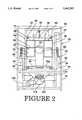
- FIG. 2is the shaker of FIG. 1 with the front panel removed to illustrate the elements contained therein;
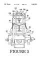
- FIG. 3is a left side elevational view with an outer frame, forming a part of the shaker of FIG. 1, removed for clarity;
- FIG. 4is a right side elevational view of the shaker of FIG. 3;
- FIG. 5is a partial side elevational view of the top portion of FIG. 4.
- a paint shaker assemblyaccording to the present invention is generally indicated at 10.
- the assembly 10has an outer cabinet 12 to prevent the splattering of paint about the environment should a paint container leak during mixing.
- the housing 12has a front panel 14 with a hatch door 16 for access to an interior compartment formed by the cabinet 12.
- Housed within sockets formed on the upper corner of a front panel 14are the controls, indicated generally at 18, for the mixing assembly 10.
- the apparatus 20has an outer, generally rectangular rigid frame 24 which preferably forms the structure for the cabinet 12. Within the outer frame is an intermediate, generally rectangular rigid frame 26.
- the intermediate frame 26is mounted to the outer frame 24 by a series of four shock and spring assemblies 28 which dampen the vibration of the intermediate frame relative to the outer frame.
- the shock assemblies 28are arranged with a pair of the shock assemblies 28 attached to each side of the intermediate frame 26.
- an upper end of each of the shocks 28is attached to a horizontal brace 30 of the intermediate frame 26, and a lower end is attached to a bracket 32 attached to a vertical corner strut 34 of the outer frame 24.
- the shocks 28are angled outward so that the top end of the shocks are upward and inward of the bottom end.
- the inner frame 36is generally vertically extending and includes four vertical corner struts 38 having top ends which are connected to each other by upper horizontal braces 40. The lower ends of the corner struts 38 are interconnected by lower horizontal braces 44.
- the guides 46are preferably covered with a friction reducing surface such as nylon or the like.
- the guides 46slidably support a shelf 48 having a flat, horizontal upper surface 48a to support a paint container 50 in an upright position.
- the shelf 48is configured to slide forward on the guides 46 so that a front portion extends forward out of the cabinet 12 to facilitate insertion and removal of the paint container 50 from the mixing apparatus 20.
- the shelf 48is preferably sized so that the shelf may support multiple containers 50 in an upright position.
- cam followers 52attached to the lateral horizontal braces 44 are cam followers 52 which halt the forward movement of the shelf 48 after the shelf is moved forward a desired distance to prevent the shelf from being pulled out of the guides 46.
- the inner frame 36also has an assembly 54 for selectively clamping the paint container 50 to the shelf 48.
- the clamping assembly 54includes an adjustable clamping cage 56.
- the clamping cage 56is vertically movable within the corner struts 38.
- the cage 56has at least one and preferably three sets of vertically spaced shelving guides 60.
- a clamping lid 64is removably and slidably disposed on one of the sets of guides 60. Attached to the lower surface of the clamping lid 64 is a set of lateral brackets 66 to slidably receive the guides 60 and fixedly hold the lid against vertical displacement relative to the cage 56.
- the lid 64may include a handle 67 for grasping.
- the cage 56also includes a pair of vertical rods 68 which form rearward stops for the clamping lid 64, and the guides 60 are mounted to four vertically extending corner posts 70. The upper ends of the posts 70 are attached to the four corners of a rectangular panel 72.
- the clamping assembly 54has a set of springs 74 connecting each of the lateral sides of the panel to a lower horizontal brace 76 on the inner frame 36. The biasing force applied by the springs 74 opposes downward movement of the clamping assembly.
- the upper ends 74a of the springs 74are attached to brackets 78 attached to each of the lateral sides of the panel 72.
- the brackets 78may also be configured to slidingly cooperate with posts 80 which extend between the lower horizontal brace 76 and an upper horizontal brace 84. The cooperation between the brackets 76 and posts 80 guides the clamping device 56 along a desired travel path relative to the inner frame 36 as the cage 56 moves up and down.
- the clamping assembly 54has a camming mechanism 86.
- the camming mechanism 86has a pair of cams 88 which are affixed to a shaft 90.
- the ends of the shaft 90are journalled in bearings 92 attached to the inner frame 36.
- the cams 88contact a plate 94 covering a portion of the upper side of the panel 70, and the cams are configured so that rotation of the cams forces the panel 70, and therefore, the cage 56 downward.
- a linkage arm 96has one end attached to the shaft 90 and the opposite end attached to the rod 98 of a linear drive device 100 such as a 24V DC, 75 lbs. push device or the like.
- the drive 100is mounted to the upper end of the inner frame 36.
- the linear drive 100has a slip clutch which is set so that when the resistance to further rotation of the shaft 90 exceeds a predetermined amount, corresponding to a desired clamping force exerted by the clamping device 56 on the paint container, further forward travel of the rod 98 is halted and the rod is maintained in the halted position.
- the cams 88are configured so that upon the maximum extension of the rod 98 (FIG. 5) and hence maximum rotation of the cams, the clamping cage 56 is forced down a distance equal to the spacing of the guides 60.
- the clamping lid 64is slidingly positioned on the sets of guides 60 which is the guide set closest to the top of the container 50 and yet horizontally above the container 50, rotation of the cam 88 causes the clamping lid 64 to come into contact and clamp the container 50 to the lower shelf 48.
- the mixing apparatus 20also includes a mechanism 104 for connecting the inner frame 36 to the intermediate frame 26 and agitating the inner frame 36.
- the agitating mechanism 104includes an electric motor 106 which rotates a drive shaft 108 through belt drive 110.
- the electric motor 106is fixedly mounted and the drive shaft 108 is rotatably mounted to the intermediate frame 26.
- Attached along the shaft 108is a set of counterweights 114, and fixedly attached to each end of the shaft is a rotary linkage 116. In each of the rotary linkages 116, one end of a pin 118 is also fixedly attached.
- the pin 118is coparallel with and spaced from axis 108a of the drive shaft 108 so that rotation of the drive shaft and hence rotation of the rotary linkage 116 causes the pin to eccentrically rotate about the axis.
- the rotary linkages 116also form integral counterweights 120.
- each of the pins 118is journalled in bearings 124 which are mounted to apron flanges 126.
- Each of the apron flanges 126is attached to the lower braces 44 of the inner frame 36.
- Pivot linkage 130includes a generally horizontal shaft 132 journalled in bearings 134 attached to the inner frame 36 and a generally horizontal shaft 136 journalled in bearings 138 attached to the intermediate frame 26. Opposite ends of elongated linkages 142 are attached to shaft 132 and shaft 136. Because the intermediate frame 26 is relatively fixed, the pivot linkage 130 guides the movement of the upper end of the inner frame 36 so that movement, such as agitation of the lower end of the inner frame is translated into pivotal movement of the upper end of the inner frame.
- the operatoropens hatch door 16 to provide access to the interior of the cabinet 12.
- the shelf 48is then pulled forward along the guides 46 until the cam followers 52 (FIG. 3) are engaged to stop the forward progress of the shelf.
- the container 50 or containersmay be placed in an upright position on the upper surface of the shelf 48.
- the shelf 48may then be slidingly pushed back along the guides 46.
- the shelf 48 and cabinet 12may be sized so that the hatch door 16 cannot be properly closed unless the shelf is in the proper position.
- the clamping lid 64is then slidingly attached to the desired shelving guide 60.
- the desired shelving guide 60is the set of shelving guides which is horizontally closest to the top of the container 50 without being below the top of the container.
- the clamping lid 64 and cabinet 12are configured so that the hatch door 16 will not close unless the clamping lid is in the proper position on the guide 60.
- the hatch door 16is then closed.
- the control of the operation of the mixer 10may be accomplished using several methods; however, in the preferred embodiment, the mixer is operated by a controller 150 as shown schematically in FIG. 1. First the time of operation is selected by manual orientation of a selector switch 152. Preferably the switch 152 may be placed in one of a discrete number of positions representing different agitating periods. In addition, a safety switch 154 may be mounted on the cabinet 12 to prevent operation of the mixing apparatus 20 unless the hatch door 16 is properly closed.
- a start switch 156is then pushed to begin the operation of the mixer 10.
- the start switch 156may include a light to indicate when the mixer 10 is operating.
- the start switch 156activates the controller 150 which sends a signal to the linear drive device 100 to extend the rod 98.
- Extension of the rod 98rotates the linkage 96 and hence the shaft 90 and cams 88.
- the cams 88rotate, the cams contactingly force down the plate 94 and panel 72 and hence the cage 56 toward the container 50. Movement of the panel 72 causes corresponding movement of the guides 60 and clamping lid 64 toward the container 50 until the clamping lid contacts the container and applies a predetermined downwardly directed force on the container. The downwardly directed force clamps the container 50 between the lid 64 and the shelf 48.
- the attachment between the guides 60 and clamping lid 64prevents the clamping lid from being upwardly displaced by the contact with the container 50.
- the slip clutch in the linear drive device 100prevents further outward extension of the rod 98.
- the controller 150sends a signal to activate the agitating mechanism 104.
- the electric motor 106rotates the drive shaft 108 (FIG. 4) which in turn rotates rotary linkage 116.
- Rotation of the rotary linkage 116propels the pin 118, and therefore, the lower end of the inner frame 36 in an eccentric path about the axis 108a of the drive shaft 108.
- This eccentric travel of the lower end of the inner frame 36imparts a shaking motion to the inner frame and hence to the shelf 48 and paint container 50.
- the counter weights 114 and 120offset the asymmetric loading imposed on the drive shaft 108 by the eccentric travel of the lower end of the inner frame 36.
- Movement of the upper end of the inner frame 36is constrained by pivot linkage 130 (FIG. 3) so that the upper end of the inner frame pivots about the upper end of the intermediate frame 26.
- the shaking motion of the inner frame 36transfers vibrations to the intermediate frame 26.
- the controller 150sends a signal to deactivate the motor 106, stopping the agitation of the inner frame 36. Referring also to FIG. 4, the controller 150 may then send a signal to activate the linear drive device 100 to retract the rod 98, hence rotating the cams 88. As the cams rotate 88, the biasing force applied by the spring 74 on the cage 56 forces the cage, including the clamping lid 64, upward away from the container 50. The container 50 is thereby released from the clamping force. After the rod 98 is fully retracted, the controller 150 sends a signal to turn off the light in the start switch 156. The operator may then open the hatch door 16 and slidingly pull the shelf 48 forward to provide access to the container 50 or containers on the shelf. The containers may then be removed and the process may be repeated for other containers.
- the controls 18may also include an emergency off switch 158, to stop the operation of the agitating mechanism 104 at any time during the operation.
- a reset button 160may be included to be activated after the emergency switch 158 has been pushed and place the mixer 150 back into the status which preceded activation of the start switch 156.
- the reset button 160may also include a light to indicate when the reset button has been activated.
Landscapes
- Chemical & Material Sciences (AREA)
- Chemical Kinetics & Catalysis (AREA)
- Mixers With Rotating Receptacles And Mixers With Vibration Mechanisms (AREA)
- Accessories For Mixers (AREA)
- Mixers Of The Rotary Stirring Type (AREA)
- Coating Apparatus (AREA)
Abstract
Description
Claims (11)
Priority Applications (7)
| Application Number | Priority Date | Filing Date | Title |
|---|---|---|---|
| US08/209,145US5462353A (en) | 1994-03-10 | 1994-03-10 | Shaker with cam operated clamp |
| AU63475/94AAU673254B2 (en) | 1994-03-10 | 1994-06-01 | Container shaker |
| IL10985394AIL109853A0 (en) | 1994-03-10 | 1994-06-01 | Container shaker |
| EP94108865AEP0671204A1 (en) | 1994-03-10 | 1994-06-09 | Container shaker |
| CA002125747ACA2125747C (en) | 1994-03-10 | 1994-06-13 | Container shaker |
| JP6163951AJPH07256077A (en) | 1994-03-10 | 1994-07-15 | Mixer |
| BR9501011ABR9501011A (en) | 1994-03-10 | 1995-03-09 | Apparatus for stirring at least one ink container |
Applications Claiming Priority (1)
| Application Number | Priority Date | Filing Date | Title |
|---|---|---|---|
| US08/209,145US5462353A (en) | 1994-03-10 | 1994-03-10 | Shaker with cam operated clamp |
Publications (1)
| Publication Number | Publication Date |
|---|---|
| US5462353Atrue US5462353A (en) | 1995-10-31 |
Family
ID=22777536
Family Applications (1)
| Application Number | Title | Priority Date | Filing Date |
|---|---|---|---|
| US08/209,145Expired - Fee RelatedUS5462353A (en) | 1994-03-10 | 1994-03-10 | Shaker with cam operated clamp |
Country Status (7)
| Country | Link |
|---|---|
| US (1) | US5462353A (en) |
| EP (1) | EP0671204A1 (en) |
| JP (1) | JPH07256077A (en) |
| AU (1) | AU673254B2 (en) |
| BR (1) | BR9501011A (en) |
| CA (1) | CA2125747C (en) |
| IL (1) | IL109853A0 (en) |
Cited By (19)
| Publication number | Priority date | Publication date | Assignee | Title |
|---|---|---|---|---|
| US5662416A (en)* | 1996-04-30 | 1997-09-02 | Dwigans, Ii; Edward Jefferson | Automatic clamping apparatus for paint mixers |
| US5906433A (en)* | 1994-10-11 | 1999-05-25 | Corob S.R.L. | Mixer for products generally disposed in containers and a unit particularly adaptable to the mixer, for supporting and clamping at least one of the containers |
| US6155707A (en)* | 1998-01-09 | 2000-12-05 | Compagnie Generale Des Matieres Nucleaires | Vibrating table with vertical acceleration |
| US20030214878A1 (en)* | 2002-05-13 | 2003-11-20 | Huckby Dwight R. | Apparatus and method for mixing a fluid dispersion disposed in a container having either a cylindrical or a square shape |
| US20040008573A1 (en)* | 2002-05-10 | 2004-01-15 | Macdonald James E. | Apparatus and method for mixing fluid dispersions disposed in containers of different sizes and construction |
| US20040013031A1 (en)* | 2002-07-22 | 2004-01-22 | Ultrablend Color, Llc | Vibrational paint shaker with managed can detection and clamping features |
| US20040202045A1 (en)* | 2001-08-10 | 2004-10-14 | Umberto Marazzi | Device for clamping a container in a mixer for fluids |
| US20040208083A1 (en)* | 2003-04-18 | 2004-10-21 | Masterchem Industries, Inc. | System for holding paint container |
| US20040233778A1 (en)* | 2001-10-09 | 2004-11-25 | Huckby Dwight R. | Apparatus and method for mixing a fluid dispersion disposed in a container having either a cylindrical or a square shape |
| US20040240314A1 (en)* | 2003-05-29 | 2004-12-02 | Masterchem Industries, Inc. | System for holding paint container |
| US20050141341A1 (en)* | 2002-04-09 | 2005-06-30 | Guido Greco | Apparatus for processing fluid products and method for the use thereof |
| US20060021984A1 (en)* | 2001-04-18 | 2006-02-02 | Nottingham John R | Container and lid assembly |
| US7014078B2 (en) | 2001-12-05 | 2006-03-21 | Masterchem Industries Llc | Container |
| US20070063561A1 (en)* | 2005-08-23 | 2007-03-22 | Schukra Of North America, Ltd. | Comfort belt spring pulley |
| US7438462B1 (en) | 2004-03-18 | 2008-10-21 | Bodie Christine J | System or method for shaking a container |
| US20090207690A1 (en)* | 2008-02-15 | 2009-08-20 | Red Devil Equipment Company | Multi-size mixer |
| US20130286768A1 (en)* | 2012-04-30 | 2013-10-31 | Ruhua SHEN | Paint can-clamping device applicable to double-gyroscopic mixer |
| US11358108B2 (en)* | 2019-03-20 | 2022-06-14 | Zhengzhou Sanhua Technology & Industry Co., Ltd. | Inner core assembly and vibration mixer |
| CN115090463A (en)* | 2022-07-19 | 2022-09-23 | 安徽协诚实业股份有限公司 | Air conditioner panel beating spraying device |
Families Citing this family (2)
| Publication number | Priority date | Publication date | Assignee | Title |
|---|---|---|---|---|
| IT1286088B1 (en)* | 1996-11-05 | 1998-07-07 | Fast Spa | PERFECTED DEVICE, FOR MIXING PAINTS CONTAINED IN JARS AND SIMILAR |
| ITBO20020671A1 (en)* | 2002-10-23 | 2004-04-24 | Corob Spa | MIXER FOR FLUID PRODUCTS AND MIXING METHOD |
Citations (38)
| Publication number | Priority date | Publication date | Assignee | Title |
|---|---|---|---|---|
| US835846A (en)* | 1906-08-07 | 1906-11-13 | Alonzo L Blalock | Churn. |
| US1448446A (en)* | 1921-06-30 | 1923-03-13 | Pfister & Vogel Leather Compan | Mixing device |
| US1463626A (en)* | 1923-05-24 | 1923-07-31 | Marrazzo Antony | Agitating machine |
| US1755763A (en)* | 1927-11-23 | 1930-04-22 | James T Barber | Drum-washing machine |
| GB478864A (en)* | 1936-03-03 | 1938-01-26 | Gerhard Hilse | Improvements in or relating to means for kneading dough, and securing basins, pots and like vessels |
| US2797902A (en)* | 1955-05-13 | 1957-07-02 | Samuel B Beugler | Mixing machine |
| US2894309A (en)* | 1957-12-10 | 1959-07-14 | Harry S Brzowski | Container clamp for liquid mixing apparatus |
| US3018092A (en)* | 1958-06-12 | 1962-01-23 | Harold T Johnson | Paint-can shaker |
| US3181841A (en)* | 1962-08-09 | 1965-05-04 | Boehm Josef | Agitating mixer |
| US3229964A (en)* | 1964-01-09 | 1966-01-18 | Diamond Alkali Co | Splitter blender apparatus |
| US3265366A (en)* | 1964-02-24 | 1966-08-09 | Warner Mfg Co | Paint can shaker and mixer |
| US3284057A (en)* | 1965-07-07 | 1966-11-08 | Robert J Duquette | Combination paint mixing and can closing devices |
| US3301534A (en)* | 1965-03-22 | 1967-01-31 | Chamberlain Corp | Paint shaker machine |
| US3388895A (en)* | 1966-08-17 | 1968-06-18 | Sherwin Williams Co | Method and apparatus for mixing contained liquids |
| US3415495A (en)* | 1967-03-15 | 1968-12-10 | Grubelic Nicholas | Apparatus for shaking paint cans |
| US3421053A (en)* | 1965-09-14 | 1969-01-07 | Nasa | Tumbler system to provide random motion |
| US3437317A (en)* | 1967-05-22 | 1969-04-08 | Le Roy F Micin | Shaker |
| US3480259A (en)* | 1968-07-01 | 1969-11-25 | Howard D Schletz | Paint mixing apparatus |
| US3542344A (en)* | 1969-07-09 | 1970-11-24 | Dynatech Corp | Method and apparatus for mixing flowable materials in closed containers |
| US3609921A (en)* | 1970-01-09 | 1971-10-05 | Cecil A Foster | Tumbling mill |
| US3706443A (en)* | 1970-08-19 | 1972-12-19 | Dynatech Corp | Agitation method and means |
| US3735962A (en)* | 1971-11-23 | 1973-05-29 | Raymond Lee Organization Inc | Automatic jar shaker |
| US3880408A (en)* | 1973-08-09 | 1975-04-29 | Winter Oy | Device for mixing of paints and toners |
| US4134689A (en)* | 1977-05-05 | 1979-01-16 | Svenska Skandex Ab | Mixing apparatus |
| US4146335A (en)* | 1978-03-20 | 1979-03-27 | General Signal Corporation | Containerized solids mixing machine |
| USD254973S (en) | 1977-05-05 | 1980-05-13 | Svenska Skandex Aktiebolag | Color mixing apparatus |
| US4235553A (en)* | 1978-09-25 | 1980-11-25 | Sears, Roebuck And Co. | Material mixer |
| US4281936A (en)* | 1979-11-13 | 1981-08-04 | Red Devil, Inc. | Paint mixing and conditioning machine |
| US4415270A (en)* | 1982-10-18 | 1983-11-15 | Red Devil Inc. | Paint mixer container clamping device with inertially driven can rotating function |
| US4422768A (en)* | 1982-03-22 | 1983-12-27 | Roy Brodshy | Paint can shaker |
| US4497581A (en)* | 1979-11-15 | 1985-02-05 | Miller Paint Equipment, Inc. | Paint shaker |
| US4588302A (en)* | 1984-01-04 | 1986-05-13 | Giordano Pizzi | Device for quickly locking the paint containing vessels in apparatus for mixing paints and the like |
| US4662760A (en)* | 1984-12-18 | 1987-05-05 | Broncorp Manufacturing Company, Inc. | Pneumatic paint shaker |
| US4789245A (en)* | 1988-01-28 | 1988-12-06 | Miller Paint Equipment, Ltd. | Disc-type apparatus for mixing paint cans |
| US4842415A (en)* | 1987-11-16 | 1989-06-27 | Imperial Chemical Industries Plc | Paint shaker |
| WO1991008045A1 (en)* | 1989-11-29 | 1991-06-13 | George Fethers & Co. Trading Pty. Ltd. | Mixing apparatus |
| US5066136A (en)* | 1986-07-01 | 1991-11-19 | Red Devil, Inc. | Vibratory mixers |
| US5197802A (en)* | 1991-09-18 | 1993-03-30 | Fluid Management Limited Partnership | Mixing apparatus |
Family Cites Families (2)
| Publication number | Priority date | Publication date | Assignee | Title |
|---|---|---|---|---|
| GB2192138B (en)* | 1986-07-01 | 1990-08-22 | Merris Dev Engineers Limited | Vibratory mixers |
| IT1264092B1 (en)* | 1993-03-25 | 1996-09-10 | Corob Srl | STIRRING MACHINE FOR MIXING OR AMALGAMING DIFFERENT PRODUCTS, IN PARTICULAR PAINTS, VARNISHES OR SIMILAR. |
- 1994
- 1994-03-10USUS08/209,145patent/US5462353A/ennot_activeExpired - Fee Related
- 1994-06-01ILIL10985394Apatent/IL109853A0/enunknown
- 1994-06-01AUAU63475/94Apatent/AU673254B2/ennot_activeCeased
- 1994-06-09EPEP94108865Apatent/EP0671204A1/ennot_activeWithdrawn
- 1994-06-13CACA002125747Apatent/CA2125747C/ennot_activeExpired - Fee Related
- 1994-07-15JPJP6163951Apatent/JPH07256077A/enactivePending
- 1995
- 1995-03-09BRBR9501011Apatent/BR9501011A/ennot_activeApplication Discontinuation
Patent Citations (39)
| Publication number | Priority date | Publication date | Assignee | Title |
|---|---|---|---|---|
| US835846A (en)* | 1906-08-07 | 1906-11-13 | Alonzo L Blalock | Churn. |
| US1448446A (en)* | 1921-06-30 | 1923-03-13 | Pfister & Vogel Leather Compan | Mixing device |
| US1463626A (en)* | 1923-05-24 | 1923-07-31 | Marrazzo Antony | Agitating machine |
| US1755763A (en)* | 1927-11-23 | 1930-04-22 | James T Barber | Drum-washing machine |
| GB478864A (en)* | 1936-03-03 | 1938-01-26 | Gerhard Hilse | Improvements in or relating to means for kneading dough, and securing basins, pots and like vessels |
| US2797902A (en)* | 1955-05-13 | 1957-07-02 | Samuel B Beugler | Mixing machine |
| US2894309A (en)* | 1957-12-10 | 1959-07-14 | Harry S Brzowski | Container clamp for liquid mixing apparatus |
| US3018092A (en)* | 1958-06-12 | 1962-01-23 | Harold T Johnson | Paint-can shaker |
| US3181841A (en)* | 1962-08-09 | 1965-05-04 | Boehm Josef | Agitating mixer |
| US3229964A (en)* | 1964-01-09 | 1966-01-18 | Diamond Alkali Co | Splitter blender apparatus |
| US3265366A (en)* | 1964-02-24 | 1966-08-09 | Warner Mfg Co | Paint can shaker and mixer |
| US3301534A (en)* | 1965-03-22 | 1967-01-31 | Chamberlain Corp | Paint shaker machine |
| US3284057A (en)* | 1965-07-07 | 1966-11-08 | Robert J Duquette | Combination paint mixing and can closing devices |
| US3421053A (en)* | 1965-09-14 | 1969-01-07 | Nasa | Tumbler system to provide random motion |
| US3388895A (en)* | 1966-08-17 | 1968-06-18 | Sherwin Williams Co | Method and apparatus for mixing contained liquids |
| US3415495A (en)* | 1967-03-15 | 1968-12-10 | Grubelic Nicholas | Apparatus for shaking paint cans |
| US3437317A (en)* | 1967-05-22 | 1969-04-08 | Le Roy F Micin | Shaker |
| US3480259A (en)* | 1968-07-01 | 1969-11-25 | Howard D Schletz | Paint mixing apparatus |
| US3542344A (en)* | 1969-07-09 | 1970-11-24 | Dynatech Corp | Method and apparatus for mixing flowable materials in closed containers |
| US3609921A (en)* | 1970-01-09 | 1971-10-05 | Cecil A Foster | Tumbling mill |
| US3706443A (en)* | 1970-08-19 | 1972-12-19 | Dynatech Corp | Agitation method and means |
| US3735962A (en)* | 1971-11-23 | 1973-05-29 | Raymond Lee Organization Inc | Automatic jar shaker |
| US3880408A (en)* | 1973-08-09 | 1975-04-29 | Winter Oy | Device for mixing of paints and toners |
| US4134689A (en)* | 1977-05-05 | 1979-01-16 | Svenska Skandex Ab | Mixing apparatus |
| USD254973S (en) | 1977-05-05 | 1980-05-13 | Svenska Skandex Aktiebolag | Color mixing apparatus |
| US4146335A (en)* | 1978-03-20 | 1979-03-27 | General Signal Corporation | Containerized solids mixing machine |
| US4235553A (en)* | 1978-09-25 | 1980-11-25 | Sears, Roebuck And Co. | Material mixer |
| US4235553B1 (en)* | 1978-09-25 | 1991-04-02 | Material mixer | |
| US4281936A (en)* | 1979-11-13 | 1981-08-04 | Red Devil, Inc. | Paint mixing and conditioning machine |
| US4497581A (en)* | 1979-11-15 | 1985-02-05 | Miller Paint Equipment, Inc. | Paint shaker |
| US4422768A (en)* | 1982-03-22 | 1983-12-27 | Roy Brodshy | Paint can shaker |
| US4415270A (en)* | 1982-10-18 | 1983-11-15 | Red Devil Inc. | Paint mixer container clamping device with inertially driven can rotating function |
| US4588302A (en)* | 1984-01-04 | 1986-05-13 | Giordano Pizzi | Device for quickly locking the paint containing vessels in apparatus for mixing paints and the like |
| US4662760A (en)* | 1984-12-18 | 1987-05-05 | Broncorp Manufacturing Company, Inc. | Pneumatic paint shaker |
| US5066136A (en)* | 1986-07-01 | 1991-11-19 | Red Devil, Inc. | Vibratory mixers |
| US4842415A (en)* | 1987-11-16 | 1989-06-27 | Imperial Chemical Industries Plc | Paint shaker |
| US4789245A (en)* | 1988-01-28 | 1988-12-06 | Miller Paint Equipment, Ltd. | Disc-type apparatus for mixing paint cans |
| WO1991008045A1 (en)* | 1989-11-29 | 1991-06-13 | George Fethers & Co. Trading Pty. Ltd. | Mixing apparatus |
| US5197802A (en)* | 1991-09-18 | 1993-03-30 | Fluid Management Limited Partnership | Mixing apparatus |
Cited By (38)
| Publication number | Priority date | Publication date | Assignee | Title |
|---|---|---|---|---|
| US5906433A (en)* | 1994-10-11 | 1999-05-25 | Corob S.R.L. | Mixer for products generally disposed in containers and a unit particularly adaptable to the mixer, for supporting and clamping at least one of the containers |
| US5662416A (en)* | 1996-04-30 | 1997-09-02 | Dwigans, Ii; Edward Jefferson | Automatic clamping apparatus for paint mixers |
| US6155707A (en)* | 1998-01-09 | 2000-12-05 | Compagnie Generale Des Matieres Nucleaires | Vibrating table with vertical acceleration |
| US20060021984A1 (en)* | 2001-04-18 | 2006-02-02 | Nottingham John R | Container and lid assembly |
| US7329041B2 (en) | 2001-04-18 | 2008-02-12 | The Sherwin-Williams Company | Method of mixing paint |
| US7517136B2 (en)* | 2001-08-10 | 2009-04-14 | Cps Color Equipment S.P.A. | Device for controlling the clamping of a container of fluid products in a mixing machine |
| US20040202045A1 (en)* | 2001-08-10 | 2004-10-14 | Umberto Marazzi | Device for clamping a container in a mixer for fluids |
| US7445373B2 (en)* | 2001-10-09 | 2008-11-04 | The Sherwin-Williams Company | Method for mixing a fluid dispersion disposed in a container having either a cylindrical or square shape |
| US7077560B2 (en) | 2001-10-09 | 2006-07-18 | The Sherwin-Williams Company | Structure for holding either a cylindrical or square shaped container during a mixing operation |
| US7325968B2 (en)* | 2001-10-09 | 2008-02-05 | The Sherwin-Williams Company | Structure for holding either a cylindrical or square shaped container during a mixing operation |
| US20050002273A1 (en)* | 2001-10-09 | 2005-01-06 | Huckby Dwight R. | Apparatus and method for mixing a fluid dispersion disposed in a container having either a cylindrical or a square shape |
| US20080049549A1 (en)* | 2001-10-09 | 2008-02-28 | The Sherwin-Williams Company | Method for Mixing A Fluid Dispersion Disposed in a Container Having Either a Cylindrical or Square Shape |
| US20060256648A1 (en)* | 2001-10-09 | 2006-11-16 | Huckby Dwight R | Apparatus and method for mixing a fluid dispersion disposed in a container having either a cylindrical or a square shape |
| US20040233778A1 (en)* | 2001-10-09 | 2004-11-25 | Huckby Dwight R. | Apparatus and method for mixing a fluid dispersion disposed in a container having either a cylindrical or a square shape |
| US7156265B2 (en) | 2001-12-05 | 2007-01-02 | Masterchem Industries Llc | Container |
| US7014078B2 (en) | 2001-12-05 | 2006-03-21 | Masterchem Industries Llc | Container |
| US20050141341A1 (en)* | 2002-04-09 | 2005-06-30 | Guido Greco | Apparatus for processing fluid products and method for the use thereof |
| US7399111B2 (en)* | 2002-05-10 | 2008-07-15 | The Sherwin-Williams Company | Apparatus and method for mixing fluid dispersions disposed in containers of different sizes and construction |
| US20040008573A1 (en)* | 2002-05-10 | 2004-01-15 | Macdonald James E. | Apparatus and method for mixing fluid dispersions disposed in containers of different sizes and construction |
| US7182505B2 (en) | 2002-05-13 | 2007-02-27 | The Sherwin-Williams Company | Apparatus and method for mixing a fluid dispersion disposed in a container having either a cylindrical or a square shape |
| US20030214878A1 (en)* | 2002-05-13 | 2003-11-20 | Huckby Dwight R. | Apparatus and method for mixing a fluid dispersion disposed in a container having either a cylindrical or a square shape |
| US20040013031A1 (en)* | 2002-07-22 | 2004-01-22 | Ultrablend Color, Llc | Vibrational paint shaker with managed can detection and clamping features |
| US6883955B2 (en) | 2002-07-22 | 2005-04-26 | Ultrablend Color, Llc | Vibrational paint shaker with managed can detection and clamping features |
| US20040208083A1 (en)* | 2003-04-18 | 2004-10-21 | Masterchem Industries, Inc. | System for holding paint container |
| US6945689B2 (en) | 2003-04-18 | 2005-09-20 | Masterchem Industries, Llc | System for holding paint container |
| US6945690B2 (en) | 2003-05-29 | 2005-09-20 | Masterchem Industries, Inc. | System for holding paint container |
| US20040240314A1 (en)* | 2003-05-29 | 2004-12-02 | Masterchem Industries, Inc. | System for holding paint container |
| US7438462B1 (en) | 2004-03-18 | 2008-10-21 | Bodie Christine J | System or method for shaking a container |
| US20070063561A1 (en)* | 2005-08-23 | 2007-03-22 | Schukra Of North America, Ltd. | Comfort belt spring pulley |
| US8157436B2 (en)* | 2008-02-15 | 2012-04-17 | Red Devil Equipment Company | Multi-size mixer |
| US20090207690A1 (en)* | 2008-02-15 | 2009-08-20 | Red Devil Equipment Company | Multi-size mixer |
| US20120201093A1 (en)* | 2008-02-15 | 2012-08-09 | Red Devil Equipment Company | Multi-size mixer |
| US8465199B2 (en)* | 2008-02-15 | 2013-06-18 | Red Devil Equipment Co. | Multi-size mixer |
| US8905629B2 (en) | 2008-02-15 | 2014-12-09 | Red Devil Equipment Company | Multi-size mixer |
| US20130286768A1 (en)* | 2012-04-30 | 2013-10-31 | Ruhua SHEN | Paint can-clamping device applicable to double-gyroscopic mixer |
| US9061258B2 (en)* | 2012-04-30 | 2015-06-23 | Shen, Ruhua | Paint can-clamping device applicable to double-gyroscopic mixer |
| US11358108B2 (en)* | 2019-03-20 | 2022-06-14 | Zhengzhou Sanhua Technology & Industry Co., Ltd. | Inner core assembly and vibration mixer |
| CN115090463A (en)* | 2022-07-19 | 2022-09-23 | 安徽协诚实业股份有限公司 | Air conditioner panel beating spraying device |
Also Published As
| Publication number | Publication date |
|---|---|
| EP0671204A1 (en) | 1995-09-13 |
| CA2125747C (en) | 2001-08-14 |
| CA2125747A1 (en) | 1995-09-11 |
| IL109853A0 (en) | 1994-10-07 |
| JPH07256077A (en) | 1995-10-09 |
| BR9501011A (en) | 1995-10-17 |
| AU673254B2 (en) | 1996-10-31 |
| AU6347594A (en) | 1995-10-05 |
Similar Documents
| Publication | Publication Date | Title |
|---|---|---|
| US5462353A (en) | Shaker with cam operated clamp | |
| US5066136A (en) | Vibratory mixers | |
| EP0617998A1 (en) | An agitator for mixing or blending various products, in particular paints, varnishes or the like | |
| CA1278277C (en) | Vending machine for heated food, notably cooked french fries | |
| US4202634A (en) | Rack for vessels and means for agitating the vessels in the rack | |
| US4134689A (en) | Mixing apparatus | |
| US5310257A (en) | Mixing apparatus | |
| US3284057A (en) | Combination paint mixing and can closing devices | |
| WO1996013323A1 (en) | Mixing apparatus | |
| US7896540B2 (en) | Automated clamping control mechanism and clamping method for fluid mixers | |
| WO2006082214A1 (en) | Double axis mixer for liquids in a receptacle, particularly for homogenization of paints | |
| EP0378056A1 (en) | Machine for dispersion, mixing and grinding | |
| US7717614B2 (en) | Clamp system for fluid mixer with pivoting upper plate for detecting container top | |
| CA2123195C (en) | Mixing assembly | |
| US20070211561A1 (en) | Bail retainer for paint mixers | |
| JPH07327608A (en) | Dishing device for frozen-paste product | |
| CN106861529A (en) | A kind of electric mixer | |
| WO2003084654A1 (en) | Apparatus for processing fluid products and method for the use thereof | |
| US2823503A (en) | Bag distending and supporting device | |
| CN215894176U (en) | A pretreatment device for pesticide residue detection | |
| US4635312A (en) | Apparatus for cleaning containers | |
| DE2739497A1 (en) | MIXER FOR FILLS CONTAINING LIQUID | |
| US2202564A (en) | Agitating machine | |
| US12397272B2 (en) | Multi-axis mixing | |
| US2589615A (en) | Mixing machine |
Legal Events
| Date | Code | Title | Description |
|---|---|---|---|
| AS | Assignment | Owner name:UNITED COATINGS COMPANY, ILLINOIS Free format text:ASSIGNMENT OF ASSIGNORS INTEREST;ASSIGNOR:GATLIN, NOEL A.;REEL/FRAME:006921/0544 Effective date:19940307 | |
| AS | Assignment | Owner name:UNITED COATINGS, INC., ILLINOIS Free format text:ASSIGNMENT OF ASSIGNORS INTEREST;ASSIGNOR:GATLIN, NOEL A.;REEL/FRAME:007022/0104 Effective date:19940525 | |
| FEPP | Fee payment procedure | Free format text:PAYOR NUMBER ASSIGNED (ORIGINAL EVENT CODE: ASPN); ENTITY STATUS OF PATENT OWNER: LARGE ENTITY | |
| AS | Assignment | Owner name:SHERWIN-WILLIAMS COMPANY, THE, OHIO Free format text:MERGER;ASSIGNOR:UNITED COATINGS, INC.;REEL/FRAME:009866/0651 Effective date:19961204 | |
| FPAY | Fee payment | Year of fee payment:4 | |
| FPAY | Fee payment | Year of fee payment:8 | |
| REMI | Maintenance fee reminder mailed | ||
| LAPS | Lapse for failure to pay maintenance fees | ||
| LAPS | Lapse for failure to pay maintenance fees | Free format text:PATENT EXPIRED FOR FAILURE TO PAY MAINTENANCE FEES (ORIGINAL EVENT CODE: EXP.); ENTITY STATUS OF PATENT OWNER: LARGE ENTITY | |
| STCH | Information on status: patent discontinuation | Free format text:PATENT EXPIRED DUE TO NONPAYMENT OF MAINTENANCE FEES UNDER 37 CFR 1.362 | |
| FP | Lapsed due to failure to pay maintenance fee | Effective date:20071031 |