US5460609A - Electromechanical inflation/deflation system - Google Patents
Electromechanical inflation/deflation systemDownload PDFInfo
- Publication number
- US5460609A US5460609AUS08/156,254US15625493AUS5460609AUS 5460609 AUS5460609 AUS 5460609AUS 15625493 AUS15625493 AUS 15625493AUS 5460609 AUS5460609 AUS 5460609A
- Authority
- US
- United States
- Prior art keywords
- inflation
- pressure
- fluid
- catheter
- drive unit
- Prior art date
- Legal status (The legal status is an assumption and is not a legal conclusion. Google has not performed a legal analysis and makes no representation as to the accuracy of the status listed.)
- Expired - Lifetime
Links
Images
Classifications
- A—HUMAN NECESSITIES
- A61—MEDICAL OR VETERINARY SCIENCE; HYGIENE
- A61M—DEVICES FOR INTRODUCING MEDIA INTO, OR ONTO, THE BODY; DEVICES FOR TRANSDUCING BODY MEDIA OR FOR TAKING MEDIA FROM THE BODY; DEVICES FOR PRODUCING OR ENDING SLEEP OR STUPOR
- A61M25/00—Catheters; Hollow probes
- A61M25/10—Balloon catheters
- A61M25/1018—Balloon inflating or inflation-control devices
- A61M25/10184—Means for controlling or monitoring inflation or deflation
- A61M25/10187—Indicators for the level of inflation or deflation
- A61M25/10188—Inflation or deflation data displays
- A—HUMAN NECESSITIES
- A61—MEDICAL OR VETERINARY SCIENCE; HYGIENE
- A61M—DEVICES FOR INTRODUCING MEDIA INTO, OR ONTO, THE BODY; DEVICES FOR TRANSDUCING BODY MEDIA OR FOR TAKING MEDIA FROM THE BODY; DEVICES FOR PRODUCING OR ENDING SLEEP OR STUPOR
- A61M25/00—Catheters; Hollow probes
- A61M25/10—Balloon catheters
- A61M25/104—Balloon catheters used for angioplasty
Definitions
- This inventiongenerally relates to inflation devices used in medical procedures. More particularly, the present invention pertains to inflation control systems suitable for inflating and deflating catheter balloons used in vascular procedures such as angioplasty performed on a patient for maintaining the patency of a blood vessel.
- Dilatation balloon cathetershave been used in increasing numbers in angioplasty procedures to dilate or enlarge blood vessels that have been partially or almost completely blocked by stenosis (a narrowing of the vessel due to injury or disease).
- Angioplasty procedureshave been used to treat stenoses in coronary arteries, peripheral arteries, urethral passages, fallopian tubes, etc.
- the procedure for dilating coronary arteriesreferred to as percutaneous transluminal coronary angioplasty (PTCA)
- PTCApercutaneous transluminal coronary angioplasty
- a guiding catheteris percutaneously introduced into the vascular system of a patient and is directed to a point near the site of the occlusion. Subsequently, a guidewire and a dilatation catheter having an inflatable balloon on the distal end thereof are introduced through the guiding catheter with the guidewire slidably disposed within an inner lumen of the dilatation catheter.
- the guidewireis advanced out of the distal end of the guiding catheter and is maneuvered into the patient's vasculature containing the lesion to be dilated, and is then advanced beyond the lesion. Thereafter, the dilatation catheter is advanced over the guidewire until the dilatation balloon is located across the lesion.
- the balloon of the dilatation catheteris filled with radiopaque liquid at relatively high pressures (e.g., generally greater than about 4 atmospheres) and is inflated to a predetermined size, preferably the same as the inner diameter of the artery at that location.
- the inflated balloonradially compresses the atherosclerotic plaque of the lesion against the inside of the artery wall to thereby dilate the lumen of the artery and allow blood to flow freely therethrough.
- the balloonis inflated and deflated several times, with the pressure maintained for several seconds during each inflation, until the desired patency in the blood vessel is obtained.
- the balloonis then deflated so that the dilatation catheter can be removed and blood flow resumed through the dilated artery.
- the physiciantypically uses an inflation system such as a syringe placed in fluid communication with the interior of the balloon.
- the physicianuses one hand to grasp the syringe body and the other hand to maneuver the plunger to pressurize or depressurize the inflation fluid as required.
- Syringe-type inflation systems of the type describedare manufactured and sold by Advanced Cardiovascular Systems, Inc. of Santa Clara, Calif. under the trademark INDEFLATOR.
- a balloon pressure displayallows the physician to monitor whether the arterial plaque causing the stenosis is subjected to a sufficiently high pressure to cause compression of the plaque. Also, the physician would like to monitor the balloon pressure to ensure that the balloon pressure limits specified by the manufacturer are not exceeded so as to cause balloon failure, and in case the balloon pressure suddenly changes, the pressure display can alert the physician of the possibility of some failure either of the artery or of the catheter itself. Furthermore, it is desirable for the physician to monitor the elapsed time of each inflation and the time between inflations so as not to deprive the patient of blood flow inside the artery beyond acceptable time periods.
- Early model inflation systemsprovided balloon pressure measurements by utilizing analog pressure gauges to correlate the force applied on the inflation device with the pressure inside the balloon.
- a microprocessorprovides control signals to a drive unit which advances or retracts the plunger of a syringe containing inflation fluid for the purpose of inflating or deflating a balloon catheter.
- the microprocessorcan be made to follow a predetermined output pattern based on the inflation pressure detected by the pressure transducer and the duration of inflation, or it can be designed for manual activation by control switches that are typically mounted on the same unit that displays the pressure and time values.
- One automated inflation deviceincludes a floor switch for operating a timer for measuring the duration of inflation and deflation of the balloon.
- floor switchesthere are some disadvantages in connection with the use of floor switches, such as the possibility of having catheter lab personnel inadvertently stepping on the floor switch. Also, floor switches accidentally may be kicked out of reach and may be subjected to contamination by spilled fluids.
- existing inflation devicesreduce the hands-on control of a physician who may desire to inflate or deflate the balloon catheter at a precise and desirable moment during the maneuvering of the catheter in the artery.
- Activation of control switches that are typically mounted away from the balloon catheterrequires the physician to give up control of the proximal end of the catheter in order to activate the control switches.
- existing inflation systemsdo not lend themselves to easy activation of the inflation device by the physician at the same time as he or she is maneuvering the balloon catheter into position in the patient's vasculature.
- the inventionis directed to an inflation/deflation system for effectuating the inflation and deflation of a dilatation balloon catheter used in vascular procedures such as angioplasty.
- the present inventionallows the physician to maintain control of the balloon pressure simultaneously as he or she is positioning the catheter in a desired location inside the patient's vascular system.
- the inventionfurther provides a safety feature that allows the physician to reduce the balloon pressure quickly in an emergency situation.
- the present systemeliminates hand-fatigue experienced by the use of manually operated inflation devices, and also eliminates the need for having a bulky inflation device in the immediate area of the vascular procedure.
- the inventionallows information relating to the pressure and inflation times to be displayed at one or more convenient locations.
- the inflation/deflation system in accordance with the present inventionincludes a fluid chamber having a plunger for pressurizing a body of inflation fluid in response to the movement of the plunger that is caused by an electromechanical motor drive unit.
- the motor drive unititself is activated in response to a signal directed from a control switch which is easily accessible to the physician.
- the inflation fluidUpon the movement of the plunger distally inside the fluid chamber, the inflation fluid is directed towards the inflation lumen of a balloon catheter via a tubing that runs between the distal end of the fluid chamber and the proximal end of the catheter's inflation lumen. As the catheter's inflation lumen is open to the interior of the balloon (or inflatable region), the inflation fluid travels through the inflation lumen and enters the balloon region and inflates the balloon.
- the deflation of the balloon regiontakes place by either slowly or rapidly reversing the movement of the motor drive unit so as to withdraw the inflation fluid from the interior of the balloon region and direct it back to the fluid chamber.
- the fluid chamberis designed so that it may also be manually withdrawn from the system by the physician.
- the plungeris designed so that it can be grasped by the physician and withdrawn from the fluid chamber to create a vacuum.
- the control switchis mounted on or is secured to the tubing close to the proximal end of the balloon catheter.
- the proximity of the control switch to the proximal end of the catheterallows the physician to keep one hand on the proximal end of the catheter for maneuvering the catheter while using his other hand on the control switch for effectuating the inflation or deflation of the balloon region.
- increased accessibility to the control switchgreatly facilitates the physician's task in positioning and inflating the balloon region of the catheter at the site of the stenosis.
- the improved accessibility of the control switchallows the physician to effectuate a rapid deflation of the balloon whenever necessary.
- the control switchmay communicate with the motor drive unit via electrically conductive wires or radiation waves (e.g., infrared or radio frequency radiation).
- radiation wavese.g., infrared or radio frequency radiation
- the control switchmay be in the form of a remote control unit that can be separate as well as attachable to a specific location, such as the tubing between the fluid chamber and the inflation lumen of the catheter.
- the present inventionalso may provide for a backup switch located on the motor drive unit or on a separate display unit.
- this backup switchwould be operable to activate the motor drive unit in a similar fashion as the primary control switch (i.e., via electrically conductive wires or radiation waves).
- the inflation/deflation system of the inventionprovides the ability to monitor the balloon pressure and the duration of inflation.
- a pressure transduceris placed at or near the proximal end of the tubing in fluid communication with the inflation fluid. Upon exposure to the fluid, the pressure transducer communicates a signal that is indicative of the balloon pressure to a display unit.
- the display unitmay also display the duration of each inflation and the time between inflations. Display of such information related to the inflation or deflation of the balloon may be displayed on a portion of the control switch, or alternatively, on a unit which may be placed either with the motor drive unit or a completely separate display unit. Also, for ease of use, display of the desirable information may take place at more than one location. For example, the pressure and inflation times may be displayed both on the separate display unit as well as on the control switch.
- control switch of the present inventioncan be made for single-use applications.
- control switch of the inventioncan be placed in a sterile, disposable cover during each application so that it may be reused in future applications on various patients.
- the present inventionallows for the detection of the presence of the fluid chamber and the pressure transducer in the system by providing for electrical connectors on the fluid chamber and the pressure transducer that mate with matching connectors in the system.
- the present inventionalso allows for the installation of the fluid chamber in an orientation with the fluid chamber outlet located at a higher elevation than the plunger so that air bubbles may rise to the upper end of the fluid chamber (towards its outlet) and be easily seen and ejected from the system.
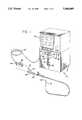
- FIG. 1is a schematic drawing of an inflation/deflation system embodying features of the invention.
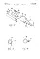
- FIG. 2is a schematic of the control switch of the inflation/deflation system shown in FIG. 1, mounted in close proximity of the proximal end of the catheter, and incorporating a display unit for displaying balloon pressure and inflation times.
- FIG. 3is a cross-sectional view of the tubing and electrical wires connecting the control switch to the display unit and plunger.
- FIG. 4is a cross-sectional view of an alternative embodiment of the components of FIG. 3.
- FIGS. 1 and 2illustrate in schematic form an inflation/deflation system 10 embodying features of the invention.
- Inflation/deflation system 10generally includes an electromechanical motor drive unit 12, a fluid chamber 14 with a plunger 16, a tubing 18, a control switch 20, a pressure transducer 22, and a display unit 24.
- Electromechanical motor drive unit 12may be in the form of a stepper motor, a DC servo motor, a hydraulic motor, a pneumatic motor, or the like. Whatever the specific type, motor drive unit 12 typically has a moveable arm 26 that is capable of directing the movement of another element, such as by pushing or pulling, that it may come in contact with. As shown in FIG. 1, arm 26 is connected to plunger 16 of fluid chamber 14. Fluid chamber 14 may be mounted in an orientation wherein fluid chamber outlet 28 is located at a higher elevation than plunger 16. Preferably, fluid chamber 14 is mounted in a vertical orientation with fluid chamber outlet 28 at the top and plunger 16 at the bottom. This arrangement enhances the system's capability for eliminating air bubbles that rise to the top.
- Fluid chamber 14 and plunger 16may be formed of a typical syringe/plunger combination with an O-ring or quad seal or with a rolling diaphragm seal for reduced friction.
- Other suitable means that can pressurize (or depressurize) and direct a quantity of fluidmay also be used.
- a length of tubing 18has its proximal end 30 connected to outlet 28 and its distal end 32 connected to the inflation lumen 34 of a balloon dilatation catheter 36.
- Inflation lumen 34extends from the proximal end 38 of dilatation catheter 36 and is in fluid communication with the interior of inflatable region (or balloon) 40 located at or near the distal end 42 of dilatation catheter 36. Accordingly, tubing 18 provides fluid communication between the interior of inflatable region 40 and the inflation fluid inside fluid chamber 14.
- Tubing 18may be made of any suitable material that can withstand the pressures associated with the inflation and deflation of a balloon catheter.
- the preferred material suitable for the tubingis polyurethane with a braided nylon. Other possible materials are PVC or flexible copolymers.
- Control switch 20activates motor drive unit 12 so that arm 26 of motor drive unit 12 applies force on plunger 16 of fluid chamber 14 and pressurizes the inflation fluid inside fluid chamber 14. Upon pressurization, the inflation fluid travels inside tubing 18 and flows into inflatable region 40 via inflation lumen 34 of dilatation catheter 36. As can be seen in FIG. 1, control switch 20 is mounted near distal end 32 of tubing 18 in close proximity with proximal end 38 of dilatation catheter 36. The preferable distance between control switch 20 and proximal end 38 of dilatation catheter 36 is approximately eighteen inches.
- control switch 20can be operated either by the physician who also is maneuvering the proximal end of the catheter as well as by a technician who may stand close to the physician without interfering with the physician's handling of the proximal end of the catheter.
- the physicianmay use one hand to activate control switch 20 to effectuate the inflation or deflation of inflatable region 40 and the other hand on the proximal end of dilatation catheter 36 to control the location of inflatable region 40.
- Control switch 20may be a rocker switch, a slide switch, a rotary switch, a pressure sensitive switch with tactile feedback, a non-electrical pneumatic control switch, or any other type of switch that may activate and deactivate motor drive unit 12.
- Control switch 20may also include an audible feedback system to notify the user of its activation.
- Control switch 20preferably includes three individual switches; an increase-pressure switch 20a, a decrease-pressure switch 20b, and a rapid-decrease-pressure switch 20c.
- pressure-increase switch 20ais released, after initially being depressed, to pressurize inflatable region 40. After inflatable region 40 is fully pressurized to a level selected by the physician, it remains fully inflated for a period of time. Thereafter, decrease-pressure switch 20b is depressed to decrease pressure in inflatable region 40. The pressure in inflatable region 40 will continue to decrease until it reaches zero, or to a value slightly less than zero atmospheres.
- rapid-decrease-pressure switch 20cis activated to rapidly decrease the pressure in inflatable region 40 to a predetermined level, usually zero atmospheres or slightly less.
- the difference between activated decrease-pressure switch 20b and rapid-decrease-pressure switch 20cis that decrease-pressure switch 20b provides a deflation pressure at a predetermined rate, while rapid-decrease-pressure switch 20c provides full current to motor drive unit 12 to cause pressure in the system to rapidly decrease to full vacuum.
- Several methods of communication between control switch 20 and motor drive unit 12may be utilized. For example, as shown in FIG. 1, one method of such communication is by using electrical wires 44 routed between control switch 20 and motor drive unit 12.
- control switch 20may be routed between control switch 20 and motor drive unit 12, while tubing 18 that carries the inflation fluid runs through control switch 20.
- control switch 20does not perform any function on tubing 18, and it is only being confined to the tubing by making the tubing run through it.
- the control switchmay be confined to the tubing and may communicate with the motor drive unit by having electrical wires 44 placed inside or embedded in the wall of tubing 18.
- electrical wires 44can be carried in a separate bundle alongside tubing 18.
- control switch 20can be provided with transmitter 46 and motor drive unit can be provided with receiver 48 suitable for sending and receiving infrared waves or radio frequency waves.
- control switch 20 and motor drive unit 12can each be provided with transmitter and receiver units.
- pressure transducer 22e.g., a piezo-resistive transducer sensitive to changes in pressure
- pressure transducer 22is positioned in the system so that it is in communication with the inflation fluid.
- the preferred position for pressure transducer 22is shown in FIG. 1 at or near the proximal end 30 of tubing 18 in communication with the inflation fluid therein.
- Other types of pressure transducersmay be used as long as they are located such that they are capable of sensing the inflation fluid.
- a force transducer(not shown) may be placed in line with arm 26 of motor drive unit 12 to measure the force it exerts on plunger 16 of fluid chamber 14. This force could be converted by appropriate means into a measurement of the pressure of the inflation fluid.
- the signal indicative of balloon pressure as measured by pressure transducer 22is directed to display unit 24 which processes the signal and displays it in analog, or preferably, in digital form.
- a signal indicative of the movement of motor drive unit 12 or plunger 16 at the start of each inflation and deflation cycleis provided to display unit 24 so that the physician may monitor the duration of each inflation or deflation and the cumulative elapsed time of inflation.
- display unit 24is preferably located on motor drive unit 12, but may also be placed at a convenient location for easy viewing (e.g., on control switch 20 as shown in FIG. 2, near other x-ray screens, or on a separately located unit). Also, the desired information may be displayed at a combination of such locations.
- plunger 16is designed to enable the physician to manually grasp it for retraction to thereby rapidly deflate inflatable region 40.
- fluid chamber 14is designed so that the physician may manually remove it from the system. Such actions for manual deflation of the inflatable region may be necessary in various emergency situations such as a power failure or a failure in one of the components of the system.
- the fluid chamber and the plungerare placed in a vertical orientation so as to allow the air bubbles that appear in the fluid chamber to be easily eliminated from the system.
- the present inventionprovides for an advantageous design in which an inflation/deflation system can be operated with ease by a physician at the same time as she is maneuvering a dilatation catheter inside the patient's vasculature.
- the inventionprovides for a display unit for monitoring inflation times and pressures and several safety features for rapid deflation of the balloon catheter. While several particular forms of the invention have been illustrated and described, it also will be appreciated that various modifications can be made to the present invention without departing from the spirit and scope thereof.
Landscapes
- Health & Medical Sciences (AREA)
- Life Sciences & Earth Sciences (AREA)
- Heart & Thoracic Surgery (AREA)
- Biomedical Technology (AREA)
- Biophysics (AREA)
- Pulmonology (AREA)
- Engineering & Computer Science (AREA)
- Anesthesiology (AREA)
- Child & Adolescent Psychology (AREA)
- Hematology (AREA)
- Animal Behavior & Ethology (AREA)
- General Health & Medical Sciences (AREA)
- Public Health (AREA)
- Veterinary Medicine (AREA)
- Vascular Medicine (AREA)
- Media Introduction/Drainage Providing Device (AREA)
Abstract
Description
This invention generally relates to inflation devices used in medical procedures. More particularly, the present invention pertains to inflation control systems suitable for inflating and deflating catheter balloons used in vascular procedures such as angioplasty performed on a patient for maintaining the patency of a blood vessel.
Dilatation balloon catheters have been used in increasing numbers in angioplasty procedures to dilate or enlarge blood vessels that have been partially or almost completely blocked by stenosis (a narrowing of the vessel due to injury or disease). Angioplasty procedures have been used to treat stenoses in coronary arteries, peripheral arteries, urethral passages, fallopian tubes, etc. Particularly, the procedure for dilating coronary arteries, referred to as percutaneous transluminal coronary angioplasty (PTCA), has provided an effective and less traumatic treatment technique than coronary by-pass surgery or other surgical treatment methods.
In a typical angioplasty procedure, a guiding catheter is percutaneously introduced into the vascular system of a patient and is directed to a point near the site of the occlusion. Subsequently, a guidewire and a dilatation catheter having an inflatable balloon on the distal end thereof are introduced through the guiding catheter with the guidewire slidably disposed within an inner lumen of the dilatation catheter. The guidewire is advanced out of the distal end of the guiding catheter and is maneuvered into the patient's vasculature containing the lesion to be dilated, and is then advanced beyond the lesion. Thereafter, the dilatation catheter is advanced over the guidewire until the dilatation balloon is located across the lesion. Once in position across the lesion, the balloon of the dilatation catheter is filled with radiopaque liquid at relatively high pressures (e.g., generally greater than about 4 atmospheres) and is inflated to a predetermined size, preferably the same as the inner diameter of the artery at that location. The inflated balloon radially compresses the atherosclerotic plaque of the lesion against the inside of the artery wall to thereby dilate the lumen of the artery and allow blood to flow freely therethrough. In a typical PTCA procedure, the balloon is inflated and deflated several times, with the pressure maintained for several seconds during each inflation, until the desired patency in the blood vessel is obtained. The balloon is then deflated so that the dilatation catheter can be removed and blood flow resumed through the dilated artery.
To inflate or deflate the balloon, the physician typically uses an inflation system such as a syringe placed in fluid communication with the interior of the balloon. The physician uses one hand to grasp the syringe body and the other hand to maneuver the plunger to pressurize or depressurize the inflation fluid as required. Syringe-type inflation systems of the type described are manufactured and sold by Advanced Cardiovascular Systems, Inc. of Santa Clara, Calif. under the trademark INDEFLATOR.
There are some drawbacks associated with a manual inflation procedure such as the one described. For example, each time the physician wants to adjust or change the location of the balloon in the artery, she must use her hands alternatingly on the proximal end of the catheter for maneuvering the balloon to the desired location and on the inflation device for pressurizing or depressurizing the balloon. Rather than switching hands between the balloon catheter and the inflation device, it is desirable for the physician to be able to simultaneously control the inflation pressure and the location of the balloon in the artery. Another drawback of manual inflation systems is that the physician may experience hand fatigue as a result of operating an inflation device for several inflation and deflation cycles, each lasting several seconds, during an angioplasty procedure. Additionally, manual inflation devices are typically bulkier than dilatation balloon catheters, and the presence of such a bulky instrument is preferably to be avoided in the immediate area of an angioplasty procedure.
In addition to the above concerns, it is desirable for the physician performing an angioplasty procedure to monitor the balloon pressure and the time of inflation. A balloon pressure display allows the physician to monitor whether the arterial plaque causing the stenosis is subjected to a sufficiently high pressure to cause compression of the plaque. Also, the physician would like to monitor the balloon pressure to ensure that the balloon pressure limits specified by the manufacturer are not exceeded so as to cause balloon failure, and in case the balloon pressure suddenly changes, the pressure display can alert the physician of the possibility of some failure either of the artery or of the catheter itself. Furthermore, it is desirable for the physician to monitor the elapsed time of each inflation and the time between inflations so as not to deprive the patient of blood flow inside the artery beyond acceptable time periods. Early model inflation systems provided balloon pressure measurements by utilizing analog pressure gauges to correlate the force applied on the inflation device with the pressure inside the balloon.
In recent years, various inflation devices have become known which are able to instantaneously monitor, display, and record balloon pressure values and inflation times. Other advances in the design of inflation systems have been directed to creating automated inflation devices, whereby a microprocessor provides control signals to a drive unit which advances or retracts the plunger of a syringe containing inflation fluid for the purpose of inflating or deflating a balloon catheter. The microprocessor can be made to follow a predetermined output pattern based on the inflation pressure detected by the pressure transducer and the duration of inflation, or it can be designed for manual activation by control switches that are typically mounted on the same unit that displays the pressure and time values. One automated inflation device includes a floor switch for operating a timer for measuring the duration of inflation and deflation of the balloon. However, there are some disadvantages in connection with the use of floor switches, such as the possibility of having catheter lab personnel inadvertently stepping on the floor switch. Also, floor switches accidentally may be kicked out of reach and may be subjected to contamination by spilled fluids.
Further, such existing inflation devices reduce the hands-on control of a physician who may desire to inflate or deflate the balloon catheter at a precise and desirable moment during the maneuvering of the catheter in the artery. Activation of control switches that are typically mounted away from the balloon catheter requires the physician to give up control of the proximal end of the catheter in order to activate the control switches. Thus, existing inflation systems do not lend themselves to easy activation of the inflation device by the physician at the same time as he or she is maneuvering the balloon catheter into position in the patient's vasculature.
What has been needed and heretofore unavailable is a simplified automated inflation/deflation system that enables the physician to effectively, easily, and simultaneously control the inflation pressure and the maneuvering of the balloon catheter. The control switch would be properly located so as to enable the physician to achieve such effective, easy, and simultaneous control. Such an inflation/deflation system would be able to easily interface with commercially available dilatation balloon catheters, and would eliminate the need for having bulky components of an inflation system in the immediate area of an angioplasty procedure. Also, such an automated inflation/deflation system would be able to monitor and display information relating to balloon pressure and inflation times at one or more convenient display locations. Lastly, it would be very desirable for such an inflation system to have a safety feature for quickly deflating the balloon in an emergency such as the appearance of a small leak in the balloon or the patient having an adverse reaction to the blockage of blood flow caused by the inflation of the balloon. The present invention fulfills these needs.
The invention is directed to an inflation/deflation system for effectuating the inflation and deflation of a dilatation balloon catheter used in vascular procedures such as angioplasty. The present invention allows the physician to maintain control of the balloon pressure simultaneously as he or she is positioning the catheter in a desired location inside the patient's vascular system. The invention further provides a safety feature that allows the physician to reduce the balloon pressure quickly in an emergency situation. In addition, the present system eliminates hand-fatigue experienced by the use of manually operated inflation devices, and also eliminates the need for having a bulky inflation device in the immediate area of the vascular procedure. Further, the invention allows information relating to the pressure and inflation times to be displayed at one or more convenient locations.
The inflation/deflation system in accordance with the present invention includes a fluid chamber having a plunger for pressurizing a body of inflation fluid in response to the movement of the plunger that is caused by an electromechanical motor drive unit. The motor drive unit itself is activated in response to a signal directed from a control switch which is easily accessible to the physician.
Upon the movement of the plunger distally inside the fluid chamber, the inflation fluid is directed towards the inflation lumen of a balloon catheter via a tubing that runs between the distal end of the fluid chamber and the proximal end of the catheter's inflation lumen. As the catheter's inflation lumen is open to the interior of the balloon (or inflatable region), the inflation fluid travels through the inflation lumen and enters the balloon region and inflates the balloon.
After each expansion of the balloon or inflatable region, the deflation of the balloon region takes place by either slowly or rapidly reversing the movement of the motor drive unit so as to withdraw the inflation fluid from the interior of the balloon region and direct it back to the fluid chamber. In order to make it possible for the physician to depressurize the balloon region in case of any failures of the motor drive unit or other emergency situations, the fluid chamber is designed so that it may also be manually withdrawn from the system by the physician. Also, the plunger is designed so that it can be grasped by the physician and withdrawn from the fluid chamber to create a vacuum.
For ease of access and control by the physician, the control switch is mounted on or is secured to the tubing close to the proximal end of the balloon catheter. The proximity of the control switch to the proximal end of the catheter allows the physician to keep one hand on the proximal end of the catheter for maneuvering the catheter while using his other hand on the control switch for effectuating the inflation or deflation of the balloon region. Thus, increased accessibility to the control switch greatly facilitates the physician's task in positioning and inflating the balloon region of the catheter at the site of the stenosis. Also, the improved accessibility of the control switch allows the physician to effectuate a rapid deflation of the balloon whenever necessary.
The control switch may communicate with the motor drive unit via electrically conductive wires or radiation waves (e.g., infrared or radio frequency radiation). In the case of communication by radiation waves, the control switch may be in the form of a remote control unit that can be separate as well as attachable to a specific location, such as the tubing between the fluid chamber and the inflation lumen of the catheter.
If desired, the present invention also may provide for a backup switch located on the motor drive unit or on a separate display unit. In case of failure (or misplacement) of the primary control switch, this backup switch would be operable to activate the motor drive unit in a similar fashion as the primary control switch (i.e., via electrically conductive wires or radiation waves).
The inflation/deflation system of the invention provides the ability to monitor the balloon pressure and the duration of inflation. For this purpose, a pressure transducer is placed at or near the proximal end of the tubing in fluid communication with the inflation fluid. Upon exposure to the fluid, the pressure transducer communicates a signal that is indicative of the balloon pressure to a display unit. The display unit may also display the duration of each inflation and the time between inflations. Display of such information related to the inflation or deflation of the balloon may be displayed on a portion of the control switch, or alternatively, on a unit which may be placed either with the motor drive unit or a completely separate display unit. Also, for ease of use, display of the desirable information may take place at more than one location. For example, the pressure and inflation times may be displayed both on the separate display unit as well as on the control switch.
The control switch of the present invention can be made for single-use applications. Alternatively, in order to lower the cost associated with the present invention, the control switch of the invention can be placed in a sterile, disposable cover during each application so that it may be reused in future applications on various patients.
The present invention allows for the detection of the presence of the fluid chamber and the pressure transducer in the system by providing for electrical connectors on the fluid chamber and the pressure transducer that mate with matching connectors in the system. The present invention also allows for the installation of the fluid chamber in an orientation with the fluid chamber outlet located at a higher elevation than the plunger so that air bubbles may rise to the upper end of the fluid chamber (towards its outlet) and be easily seen and ejected from the system.
These and other advantages of the invention will become more apparent from the following detailed description thereof when taken in conjunction with the accompanying exemplary drawings.
FIG. 1 is a schematic drawing of an inflation/deflation system embodying features of the invention.
FIG. 2 is a schematic of the control switch of the inflation/deflation system shown in FIG. 1, mounted in close proximity of the proximal end of the catheter, and incorporating a display unit for displaying balloon pressure and inflation times.
FIG. 3 is a cross-sectional view of the tubing and electrical wires connecting the control switch to the display unit and plunger.
FIG. 4 is a cross-sectional view of an alternative embodiment of the components of FIG. 3.
FIGS. 1 and 2 illustrate in schematic form an inflation/deflation system 10 embodying features of the invention. Inflation/deflation system 10 generally includes an electromechanicalmotor drive unit 12, afluid chamber 14 with aplunger 16, atubing 18, acontrol switch 20, apressure transducer 22, and adisplay unit 24.
Electromechanicalmotor drive unit 12 may be in the form of a stepper motor, a DC servo motor, a hydraulic motor, a pneumatic motor, or the like. Whatever the specific type,motor drive unit 12 typically has amoveable arm 26 that is capable of directing the movement of another element, such as by pushing or pulling, that it may come in contact with. As shown in FIG. 1,arm 26 is connected to plunger 16 offluid chamber 14.Fluid chamber 14 may be mounted in an orientation whereinfluid chamber outlet 28 is located at a higher elevation thanplunger 16. Preferably,fluid chamber 14 is mounted in a vertical orientation withfluid chamber outlet 28 at the top andplunger 16 at the bottom. This arrangement enhances the system's capability for eliminating air bubbles that rise to the top.Fluid chamber 14 andplunger 16 may be formed of a typical syringe/plunger combination with an O-ring or quad seal or with a rolling diaphragm seal for reduced friction. Other suitable means that can pressurize (or depressurize) and direct a quantity of fluid may also be used.
Asarm 26 forces plunger 16 insidefluid chamber 14, the inflation fluid insidefluid chamber 14 is pressurized, and is directed out offluid chamber outlet 28. The reverse movement ofarm 26 reduces the pressure of the inflation fluid, and directs the fluid back inside the fluid chamber. A length oftubing 18 has itsproximal end 30 connected tooutlet 28 and itsdistal end 32 connected to theinflation lumen 34 of aballoon dilatation catheter 36.Inflation lumen 34 extends from theproximal end 38 ofdilatation catheter 36 and is in fluid communication with the interior of inflatable region (or balloon) 40 located at or near thedistal end 42 ofdilatation catheter 36. Accordingly,tubing 18 provides fluid communication between the interior ofinflatable region 40 and the inflation fluid insidefluid chamber 14.Tubing 18 may be made of any suitable material that can withstand the pressures associated with the inflation and deflation of a balloon catheter. The preferred material suitable for the tubing is polyurethane with a braided nylon. Other possible materials are PVC or flexible copolymers.
Another method of communication betweencontrol switch 20 andmotor drive unit 12 includes the use of electromagnetic radiation waves. For example, as shown in FIGS. 1 and 2, control switch 20 can be provided withtransmitter 46 and motor drive unit can be provided withreceiver 48 suitable for sending and receiving infrared waves or radio frequency waves. For a two-way communication, as shown in FIGS. 1 and 2,control switch 20 andmotor drive unit 12 can each be provided with transmitter and receiver units.
In order to monitor the pressure insideinflatable region 40, pressure transducer 22 (e.g., a piezo-resistive transducer sensitive to changes in pressure) is positioned in the system so that it is in communication with the inflation fluid. The preferred position forpressure transducer 22 is shown in FIG. 1 at or near theproximal end 30 oftubing 18 in communication with the inflation fluid therein. Other types of pressure transducers may be used as long as they are located such that they are capable of sensing the inflation fluid. As another example, a force transducer (not shown) may be placed in line witharm 26 ofmotor drive unit 12 to measure the force it exerts onplunger 16 offluid chamber 14. This force could be converted by appropriate means into a measurement of the pressure of the inflation fluid.
The signal indicative of balloon pressure as measured bypressure transducer 22 is directed to displayunit 24 which processes the signal and displays it in analog, or preferably, in digital form. In addition, a signal indicative of the movement ofmotor drive unit 12 orplunger 16 at the start of each inflation and deflation cycle is provided to displayunit 24 so that the physician may monitor the duration of each inflation or deflation and the cumulative elapsed time of inflation. As shown in FIG. 1,display unit 24 is preferably located onmotor drive unit 12, but may also be placed at a convenient location for easy viewing (e.g., oncontrol switch 20 as shown in FIG. 2, near other x-ray screens, or on a separately located unit). Also, the desired information may be displayed at a combination of such locations.
In addition to the above features, as an added safety feature,plunger 16 is designed to enable the physician to manually grasp it for retraction to thereby rapidly deflateinflatable region 40. As another safety feature,fluid chamber 14 is designed so that the physician may manually remove it from the system. Such actions for manual deflation of the inflatable region may be necessary in various emergency situations such as a power failure or a failure in one of the components of the system. Furthermore, in the present invention, as shown in FIG. 1, the fluid chamber and the plunger are placed in a vertical orientation so as to allow the air bubbles that appear in the fluid chamber to be easily eliminated from the system.
From the above, it is evident that the present invention provides for an advantageous design in which an inflation/deflation system can be operated with ease by a physician at the same time as she is maneuvering a dilatation catheter inside the patient's vasculature. In addition, the invention provides for a display unit for monitoring inflation times and pressures and several safety features for rapid deflation of the balloon catheter. While several particular forms of the invention have been illustrated and described, it also will be appreciated that various modifications can be made to the present invention without departing from the spirit and scope thereof.
Claims (5)
1. An inflation/deflation system, comprising:
a catheter having an inflatable region at its distal end and an inflation lumen providing a fluid path between a proximal end of said catheter and the interior of said inflatable region;
a fluid chamber having a plunger for pressurizing a quantity of inflation fluid contained in said fluid chamber;
a conduit located between said fluid chamber and said catheter inflation lumen for directing said inflation fluid between said fluid chamber and the interior of said inflation region;
a motor drive unit coupled to the plunger to control the position of the plunger in the fluid chamber in response to control signals to thereby control the inflation fluid pressure between said fluid chamber and the interior of said inflatable region; and
a control switch located near said proximal end of said catheter and remote from but in communication with said drive unit, said control switch adapted to provide control signals to the drive unit to cause the drive unit to control the movement of said plunger and thereby pressurize or depressurize said inflation fluid in said fluid chamber, and having a rapid decrease/pressure button which, when activated, controls the motor drive unit to cause fluid pressure in said inflatable region to rapidly decrease to a predetermined level.
2. The inflation/deflation system of claim 1, wherein said rapid decrease/pressure button, when activated, controls the motor drive unit to rapidly decrease pressure in said inflatable region to a negative pressure value.
3. The inflation/deflation system of claim 2 wherein:
the fluid chamber comprises a syringe having a body with the plunger movably mounted in the syringe body for altering the internal volume of the syringe body to thereby control the pressure of the fluid, the body having a first end with an outlet port formed in the first end with a tapered transition member between the body and the outlet port and the syringe is oriented vertically so that the outlet is at a higher elevation than the remainder of the syringe so that bubbles in the syringe rise to the outlet port; and
the motor drive unit is connected to the plunger for moving the plunger in relation to the syringe body to alter the volume of the syringe body and the pressure of the quantity of fluid.
4. The inflation/deflation system of claim 3 further comprising:
sensing means for determining the pressure of the fluid and for generating a sensor signal indicative of the determined pressure; and
means for transmitting said signal wherein the control switch comprises a display unit that receives the sensor signal from said transmitting means and displays the pressure of said fluid in response thereto.
5. The inflation/deflation system of claim 4 wherein the display unit presents pressure and pressure duration.
Priority Applications (1)
| Application Number | Priority Date | Filing Date | Title |
|---|---|---|---|
| US08/156,254US5460609A (en) | 1993-11-22 | 1993-11-22 | Electromechanical inflation/deflation system |
Applications Claiming Priority (1)
| Application Number | Priority Date | Filing Date | Title |
|---|---|---|---|
| US08/156,254US5460609A (en) | 1993-11-22 | 1993-11-22 | Electromechanical inflation/deflation system |
Publications (1)
| Publication Number | Publication Date |
|---|---|
| US5460609Atrue US5460609A (en) | 1995-10-24 |
Family
ID=22558775
Family Applications (1)
| Application Number | Title | Priority Date | Filing Date |
|---|---|---|---|
| US08/156,254Expired - LifetimeUS5460609A (en) | 1993-11-22 | 1993-11-22 | Electromechanical inflation/deflation system |
Country Status (1)
| Country | Link |
|---|---|
| US (1) | US5460609A (en) |
Cited By (85)
| Publication number | Priority date | Publication date | Assignee | Title |
|---|---|---|---|---|
| US5722979A (en)* | 1997-04-08 | 1998-03-03 | Schneider (Usa) Inc. | Pressure assisted ultrasonic balloon catheter and method of using same |
| US5808203A (en)* | 1997-05-12 | 1998-09-15 | Medrad, Inc. | Fluid pressure measurement devices |
| US5916196A (en)* | 1995-05-26 | 1999-06-29 | Schneider (Europe) Ag | Fluid delivery system for a balloon catheter |
| US6104941A (en)* | 1998-03-26 | 2000-08-15 | Ge Marquette Medical Systems, Inc. | Physiological sensor |
| US6306117B1 (en) | 1993-10-28 | 2001-10-23 | Medrad, Inc. | Multi-patient fluid dispensing |
| EP1199083A1 (en)* | 2000-10-16 | 2002-04-24 | Probitas Pharma, S.A. | Apparatus for the inflation and deflation of balloon catheters and a method for its use |
| US6385483B1 (en) | 1994-09-21 | 2002-05-07 | Medrad, Inc. | Patient specific dosing contrast delivery systems and methods |
| US6394977B1 (en)* | 1998-03-25 | 2002-05-28 | Merit Medical Systems, Inc. | Pressure gauge with digital stepping motor and reusable transfer plug |
| US6442418B1 (en) | 1993-10-28 | 2002-08-27 | Medrad, Inc. | Total system for contrast delivery |
| US20030122095A1 (en)* | 2001-12-07 | 2003-07-03 | Wilson Robert F. | Low pressure measurement devices in high pressure environments |
| WO2003097151A1 (en)* | 2002-05-15 | 2003-11-27 | Till Neumann | Device for treating cardiovascular diseases |
| US20040122369A1 (en)* | 2002-12-20 | 2004-06-24 | Schriver Ralph H. | Front load pressure jacket system with syringe holder and light illumination |
| US20040122370A1 (en)* | 2002-12-20 | 2004-06-24 | Joyce Thomas P. | Front load pressure jacket system with pivotal locking members |
| US20040143212A1 (en)* | 2000-10-18 | 2004-07-22 | Trombley Frederick W. | Powered injector systems and injector control |
| US20040193045A1 (en)* | 2003-02-21 | 2004-09-30 | Nelson Scarborough | Spinal fluid introduction |
| US20040254533A1 (en)* | 2002-12-20 | 2004-12-16 | Schriver Ralph H. | Fluid injection apparatus with front load pressure jacket, light illumination, and syringe sensing |
| US20040260238A1 (en)* | 2003-05-05 | 2004-12-23 | Call Evan W. | Infusion syringe |
| US20050004518A1 (en)* | 2003-05-05 | 2005-01-06 | Call Evan W. | Infusion syringe |
| US20050209601A1 (en)* | 2004-03-22 | 2005-09-22 | Disc Dynamics, Inc. | Multi-stage biomaterial injection system for spinal implants |
| US20050234407A1 (en)* | 2004-04-16 | 2005-10-20 | Spohn Michael A | Fluid delivery system, fluid control device, and methods associated with the fluid delivery system and fluid control device |
| US20050273056A1 (en)* | 2004-04-08 | 2005-12-08 | Haury John A | Control device for a fluid delivery system |
| US20060095063A1 (en)* | 2004-11-04 | 2006-05-04 | Fujinon Corporation | Balloon controller for endoscopic apparatus |
| US20070038025A1 (en)* | 2004-03-19 | 2007-02-15 | Olympus Corporation | Endoscope balloon control device |
| US20070129705A1 (en)* | 2005-12-01 | 2007-06-07 | Medrad, Inc. | Fluid delivery system, fluid path, and medical connector for use with the fluid delivery system and fluid path |
| US20070197963A1 (en)* | 2005-06-21 | 2007-08-23 | Griffiths David M | Medical fluid injection and inflation system |
| US20070213656A1 (en)* | 2006-03-08 | 2007-09-13 | Arthur Ferdinand | Device for outputting a qualitative indication associated with the inflation of an expandable member |
| US20070244435A1 (en)* | 2006-04-12 | 2007-10-18 | Hicks Jeffrey H | Fluid delivery system with pump cassette |
| US20070250008A1 (en)* | 2006-04-20 | 2007-10-25 | Gelblum Eugene A | Fluid injection apparatus and adaptor pump therefor |
| USD562447S1 (en) | 2004-01-30 | 2008-02-19 | Physician Industries, Inc. | Portion of a syringe |
| US20080086087A1 (en)* | 2004-04-16 | 2008-04-10 | Spohn Michael A | Fluid delivery system including a fluid path set with sterile check valve connector |
| US20080172006A1 (en)* | 2007-01-15 | 2008-07-17 | Medrad, Inc. | Patency Check Compatible Check Valve And Fluid Delivery System Including The Patency Check Compatible Check Valve |
| USD579561S1 (en) | 2004-01-30 | 2008-10-28 | Physician Industries, Inc. | Portion of a syringe |
| US20090076439A1 (en)* | 2007-09-14 | 2009-03-19 | Dollar Michael L | Inflation System for Balloon Catheter |
| US7641668B2 (en) | 2003-05-16 | 2010-01-05 | Scimed Life Systems, Inc. | Fluid delivery system and related methods of use |
| US20100076307A1 (en)* | 2006-12-22 | 2010-03-25 | Medrad, Inc. | Flow based pressure isolation mechanism for a fluid delivery system |
| US20100114040A1 (en)* | 2008-11-05 | 2010-05-06 | Medrad, Inc. | Fluid mixing control device for a multi-fluid delivery system |
| US20100204573A1 (en)* | 2007-09-14 | 2010-08-12 | Medrad, Inc. | Fluid path set providing gravity flow prevention |
| US20100222768A1 (en)* | 2007-10-19 | 2010-09-02 | Medrad, Inc. | Methods for capacitance volume correction in fluid delivery systems |
| US20100298699A1 (en)* | 2007-10-30 | 2010-11-25 | Medrad Inc. | System and Method for Proportional Mixing and Continuous Delivery of Fluids |
| US20110082450A1 (en)* | 2009-10-02 | 2011-04-07 | Cardiofocus, Inc. | Cardiac ablation system with inflatable member having multiple inflation settings |
| US7925330B2 (en) | 2004-11-24 | 2011-04-12 | Medrad, Inc. | Devices, systems and methods for determining parameters of one or more phases of an injection procedure |
| US20110092828A1 (en)* | 2004-04-16 | 2011-04-21 | Spohn Michael A | Fluid Delivery System, Fluid Path Set, and Pressure Isolation Mechanism with Hemodynamic Pressure Dampening Correction |
| WO2012155035A1 (en) | 2011-05-12 | 2012-11-15 | Medrad, Inc. | Fluid injection system having various systems for controlling an injection procedure |
| US20140222009A1 (en)* | 2011-09-09 | 2014-08-07 | O.P.A. Medical. S.R.L. | Assembly for kyphoplasty procedures |
| US9008759B2 (en) | 2007-07-17 | 2015-04-14 | Bayer Medical Care Inc. | Devices and systems for determination of parameters for a procedure, for estimation of cardiopulmonary function and for fluid delivery |
| US9259527B2 (en) | 2012-10-17 | 2016-02-16 | Bayer Healthcare Llc | Fluid delivery system with high and low pressure hand manifold |
| US9302044B2 (en) | 2006-12-29 | 2016-04-05 | Bayer Healthcare Llc | Patient-based parameter generation systems for medical injection procedures |
| US9320846B2 (en) | 2012-08-28 | 2016-04-26 | Osprey Medical, Inc. | Devices and methods for modulating medium delivery |
| US9421330B2 (en) | 2008-11-03 | 2016-08-23 | Bayer Healthcare Llc | Mitigation of contrast-induced nephropathy |
| US9433730B2 (en) | 2013-03-14 | 2016-09-06 | Bayer Healthcare Llc | Fluid mixing control device for a multi-fluid delivery system |
| US9486579B2 (en) | 2012-04-03 | 2016-11-08 | Bayer Healthcare Llc | High pressure sensor for use with a fluid delivery system |
| US9616166B2 (en) | 2004-11-16 | 2017-04-11 | Bayer Healthcare Llc | Systems and methods of determining injection protocols for diagnostic imaging procedures |
| US9649436B2 (en) | 2011-09-21 | 2017-05-16 | Bayer Healthcare Llc | Assembly method for a fluid pump device for a continuous multi-fluid delivery system |
| US9707342B2 (en) | 2012-06-07 | 2017-07-18 | Bayer Healthcare | Shield adapted to fit medical injector syringe |
| US9750953B2 (en) | 2008-06-06 | 2017-09-05 | Bayer Healthcare Llc | Apparatus and methods for delivery of fluid injection boluses to patients and handling harmful fluids |
| US9889288B2 (en) | 2012-06-07 | 2018-02-13 | Bayer Healthcare Llc | Tubing connectors |
| US9895488B2 (en) | 2014-06-27 | 2018-02-20 | Bayer Healthcare Llc | Conductive coding of syringe information |
| US9949704B2 (en) | 2012-05-14 | 2018-04-24 | Bayer Healthcare Llc | Systems and methods for determination of pharmaceutical fluid injection protocols based on x-ray tube voltage |
| US9959389B2 (en) | 2010-06-24 | 2018-05-01 | Bayer Healthcare Llc | Modeling of pharmaceutical propagation and parameter generation for injection protocols |
| US9999718B2 (en) | 2012-08-28 | 2018-06-19 | Osprey Medical, Inc. | Volume monitoring device utilizing light-based systems |
| US10010673B2 (en) | 2012-08-28 | 2018-07-03 | Osprey Medical, Inc. | Adjustable medium diverter |
| US10022497B2 (en) | 2012-08-28 | 2018-07-17 | Osprey Medical, Inc. | Reservoir for collection and reuse of diverted medium |
| US10272263B2 (en) | 2012-06-07 | 2019-04-30 | Bayer Healthcare Llc | Radiopharmaceutical delivery and tube management system |
| US10350006B2 (en) | 2008-12-03 | 2019-07-16 | Biosense Webster, Inc. | Prevention of kinks in catheter irrigation tubes |
| US10413677B2 (en) | 2012-08-28 | 2019-09-17 | Osprey Medical, Inc. | Volume monitoring device |
| US10507319B2 (en) | 2015-01-09 | 2019-12-17 | Bayer Healthcare Llc | Multiple fluid delivery system with multi-use disposable set and features thereof |
| CN111513820A (en)* | 2020-04-29 | 2020-08-11 | 上海市第一人民医院 | A retroperitoneal approach surgical space expansion system |
| US10898638B2 (en) | 2016-03-03 | 2021-01-26 | Bayer Healthcare Llc | System and method for improved fluid delivery in multi-fluid injector systems |
| CN113289216A (en)* | 2021-06-24 | 2021-08-24 | 苏州中荟医疗科技有限公司 | Conduit and seismic wave generation system |
| US11116892B2 (en) | 2012-08-28 | 2021-09-14 | Osprey Medical, Inc. | Medium injection diversion and measurement |
| US11135375B2 (en) | 2012-08-28 | 2021-10-05 | Osprey Medical, Inc. | Volume monitoring systems |
| US11141535B2 (en) | 2017-08-31 | 2021-10-12 | Bayer Healthcare Llc | Fluid path impedance assessment for improving fluid delivery performance |
| US11278853B2 (en) | 2013-03-13 | 2022-03-22 | Bayer Healthcare Llc | Method for controlling fluid accuracy and backflow compensation |
| US11464949B2 (en) | 2018-04-12 | 2022-10-11 | The Regents Of The University Of Michigan | System for effecting and controlling oscillatory pressure within balloon catheters for fatigue fracture of calculi |
| US11478581B2 (en) | 2017-08-31 | 2022-10-25 | Bayer Healthcare Llc | Fluid injector system volume compensation system and method |
| US11499841B2 (en) | 2019-04-12 | 2022-11-15 | Osprey Medical, Inc. | Energy-efficient position determining with multiple sensors |
| US11598664B2 (en) | 2017-08-31 | 2023-03-07 | Bayer Healthcare Llc | Injector pressure calibration system and method |
| US11607489B2 (en) | 2017-05-26 | 2023-03-21 | Bayer Healthcare Llc | Injector state logic with hemodynamic monitoring |
| US11779702B2 (en) | 2017-08-31 | 2023-10-10 | Bayer Healthcare Llc | Method for dynamic pressure control in a fluid injector system |
| US11786652B2 (en) | 2017-08-31 | 2023-10-17 | Bayer Healthcare Llc | System and method for drive member position and fluid injector system mechanical calibration |
| US12208239B2 (en) | 2018-08-28 | 2025-01-28 | Bayer Healthcare Llc | Fluid injector system, method of preventing fluid backflow, and computer program product |
| US12251544B2 (en) | 2018-04-19 | 2025-03-18 | Bayer Healthcare Llc | System and method for air detection in fluid injector |
| US12263326B2 (en) | 2016-11-14 | 2025-04-01 | Bayer Healthcare Llc | Methods and systems for verifying the contents of a syringe used for medical fluid delivery |
| US12279782B2 (en) | 2021-02-04 | 2025-04-22 | Amplitude Vascular Systems, Inc. | Pulsatile balloon catheter systems and methods of using the same |
| US12427249B2 (en) | 2018-08-28 | 2025-09-30 | Bayer Healthcare Llc | Fluid injector system with improved ratio performance |
Citations (61)
| Publication number | Priority date | Publication date | Assignee | Title |
|---|---|---|---|---|
| US3623474A (en)* | 1966-07-25 | 1971-11-30 | Medrad Inc | Angiographic injection equipment |
| US3698381A (en)* | 1970-12-30 | 1972-10-17 | Avco Corp | Monitoring system for physiological support systems |
| US3701345A (en)* | 1970-09-29 | 1972-10-31 | Medrad Inc | Angiographic injector equipment |
| US3720199A (en)* | 1971-05-14 | 1973-03-13 | Avco Corp | Safety connector for balloon pump |
| US3985123A (en)* | 1975-07-17 | 1976-10-12 | Avco Everett Research Laboratory, Inc. | Method and means for monitoring cardiac output |
| US4006736A (en)* | 1974-11-27 | 1977-02-08 | Medrad, Inc. | Angiographic injector |
| US4056043A (en)* | 1975-10-28 | 1977-11-01 | Johnson Controls, Inc. | Fluid power piston actuators |
| US4106002A (en)* | 1976-12-06 | 1978-08-08 | Hogue Jr Robert J | Tourniquet pressure monitor |
| US4231715A (en)* | 1977-10-21 | 1980-11-04 | Schneider Medintag Ag | Clinically usable pump apparatus for a dilatation device |
| US4332254A (en)* | 1980-11-17 | 1982-06-01 | Advanced Catheter Systems, Inc. | System for filling and inflating and deflating a vascular dilating cathether assembly |
| US4370982A (en)* | 1980-09-10 | 1983-02-01 | Medrad, Inc. | Method and apparatus for injecting and for controlling the pressure of fluid being injected into a catheter |
| US4439185A (en)* | 1981-10-21 | 1984-03-27 | Advanced Cardiovascular Systems, Inc. | Inflating and deflating device for vascular dilating catheter assembly |
| US4439186A (en)* | 1981-09-29 | 1984-03-27 | Adolf Kuhl | Dilation device |
| US4444335A (en)* | 1981-09-14 | 1984-04-24 | Merck & Co., Inc. | Delivery of adjustable quantities of materials |
| US4493704A (en)* | 1982-11-29 | 1985-01-15 | Oximetrix, Inc. | Portable fluid infusion apparatus |
| US4576181A (en)* | 1984-05-09 | 1986-03-18 | Utah Medical Products | Disposable pressure transducer apparatus for medical use |
| US4583974A (en)* | 1984-04-04 | 1986-04-22 | Kokernak Denis T | Syringe for balloon dilation catheters |
| US4583917A (en)* | 1983-06-17 | 1986-04-22 | Shah Nayan S | Pressure regulating and monitoring device |
| US4608994A (en)* | 1984-12-20 | 1986-09-02 | Matsushita Electric Industrial Co., Ltd. | Physiological monitoring system |
| US4610256A (en)* | 1984-09-25 | 1986-09-09 | Utah Medical Products, Inc. | Pressure transducer |
| US4651738A (en)* | 1985-08-02 | 1987-03-24 | Baylor College Of Medicine | Method and device for performing transluminal angioplasty |
| US4654027A (en)* | 1985-10-30 | 1987-03-31 | Dragan William B | Vascular dilating device |
| US4655749A (en)* | 1985-09-30 | 1987-04-07 | Fischione Eugene A | Angioplasty pressure controller |
| US4677982A (en)* | 1981-12-31 | 1987-07-07 | New York University | Infrared transcutaneous communicator and method of using same |
| US4677980A (en)* | 1984-06-06 | 1987-07-07 | Medrad, Inc. | Angiographic injector and angiographic syringe for use therewith |
| US4694409A (en)* | 1984-06-25 | 1987-09-15 | Monorail, Inc. | Microprocessor based air inflation control system |
| US4723938A (en)* | 1986-12-24 | 1988-02-09 | Schneider-Shiley (Usa) Inc. | Single plunger inflation device for angioplasty catheter |
| US4743230A (en)* | 1985-09-05 | 1988-05-10 | Advanced Cardiovascular Systems, Inc. | Inflating and deflating device for balloon dilatation catheters |
| US4758223A (en)* | 1986-07-02 | 1988-07-19 | Schneider-Shiley (Usa) Inc. | Inflation device for angioplasty catheter |
| US4781192A (en)* | 1986-12-22 | 1988-11-01 | Baylor College Of Medicine | Balloon dilation apparatus |
| US4795431A (en)* | 1987-01-14 | 1989-01-03 | Walling Peter T | Syringe and catheter apparatus |
| US4796606A (en)* | 1986-08-27 | 1989-01-10 | Aisin Seiki Kabushiki Kaisha | Drive unit for medical pump |
| US4808165A (en)* | 1987-09-03 | 1989-02-28 | Carr Ann M | Inflation/deflation device for balloon catheter |
| US4832692A (en)* | 1986-10-14 | 1989-05-23 | Cordis Corporation | Inflation syringe assembly for percutaneous transluminal angioplasty |
| US4838864A (en)* | 1987-11-13 | 1989-06-13 | Mansfield Scientific, Inc. | Pressure controller |
| US4854324A (en)* | 1984-01-31 | 1989-08-08 | Medrad, Inc. | Processor-controlled angiographic injector device |
| US4872483A (en)* | 1987-12-31 | 1989-10-10 | International Medical Products, Inc. | Conveniently hand held self-contained electronic manometer and pressure modulating device |
| US4911695A (en)* | 1989-04-03 | 1990-03-27 | Coeur Laboratories, Inc. | Plunger for power-driven angiographic syringe, and syringe and power injector system utilizing same |
| US4919121A (en)* | 1989-02-06 | 1990-04-24 | Schneider (Usa) Inc., A Pfizer Company | Inflation device for angioplasty catheter |
| WO1990004987A1 (en)* | 1988-11-03 | 1990-05-17 | Applied Vascular Devices, Inc. | An improved device for power injection of fluids |
| US4929238A (en)* | 1988-11-23 | 1990-05-29 | Coeur Laboratories, Inc. | Multi-pressure injector device |
| US4940459A (en)* | 1988-10-12 | 1990-07-10 | Mallinckrodt, Inc. | Inflation device for balloon catheter |
| US4952928A (en)* | 1988-08-29 | 1990-08-28 | B. I. Incorporated | Adaptable electronic monitoring and identification system |
| WO1990011040A2 (en)* | 1989-03-17 | 1990-10-04 | Merit Medical Systems, Inc. | System and method for monitoring, displaying and recording balloon catheter inflation data |
| US4985015A (en)* | 1987-11-25 | 1991-01-15 | Siemens Aktiengesellschaft | Dosing device for controlled injection of liquid from a reservoir into an organism |
| US5004472A (en)* | 1988-08-10 | 1991-04-02 | Wallace William D | Medical pressure sensing and display system |
| US5007904A (en)* | 1989-01-19 | 1991-04-16 | Coeur Laboratories, Inc. | Plunger for power injector angiographic syringe, and syringe comprising same |
| US5015233A (en)* | 1989-04-17 | 1991-05-14 | Freedom Machine, Inc. | Pneumatic inflation device |
| US5019041A (en)* | 1988-03-08 | 1991-05-28 | Scimed Life Systems, Inc. | Balloon catheter inflation device |
| US5047015A (en)* | 1989-03-17 | 1991-09-10 | Merit Medical Systems, Inc. | Locking syringe |
| US5057078A (en)* | 1989-03-17 | 1991-10-15 | Merit Medical Systems, Inc. | Locking syringe |
| US5084060A (en)* | 1989-02-15 | 1992-01-28 | Freund Precision, Inc. | Apparatus for enlarging a vessel or clearing obstructive tissue from a vessel according to vessel compliance |
| WO1992006735A1 (en)* | 1990-10-23 | 1992-04-30 | Angeion Corporation | Inflation system for a balloon catheter |
| WO1992015359A1 (en)* | 1991-03-04 | 1992-09-17 | Merit Medical Systems, Inc. | Locking syringe with thread-release lock |
| US5152776A (en)* | 1990-04-03 | 1992-10-06 | Cordis Corporation | Balloon inflation device |
| US5163904A (en)* | 1991-11-12 | 1992-11-17 | Merit Medical Systems, Inc. | Syringe apparatus with attached pressure gauge |
| US5201753A (en)* | 1989-03-17 | 1993-04-13 | Merit Medical Systems, Inc. | Totally self-contained, digitally controlled, disposable syringe inflation system, and method for monitoring, displaying and recording balloon catheter inflation data |
| US5215523A (en)* | 1991-05-30 | 1993-06-01 | Eli Williams | Balloon catheter inflation syringe with remote display |
| US5218970A (en)* | 1990-12-05 | 1993-06-15 | Smiths Industries Public Limited Company | Tracheal tube cuff pressure monitor |
| US5259838A (en)* | 1992-06-18 | 1993-11-09 | Merit Medical Systems, Inc. | Syringe apparatus with attached pressure gauge and timer |
| US5273537A (en)* | 1992-03-06 | 1993-12-28 | Scimed Life Systems, Inc. | Power-assisted inflation apparatus |
- 1993
- 1993-11-22USUS08/156,254patent/US5460609A/ennot_activeExpired - Lifetime
Patent Citations (69)
| Publication number | Priority date | Publication date | Assignee | Title |
|---|---|---|---|---|
| US3623474A (en)* | 1966-07-25 | 1971-11-30 | Medrad Inc | Angiographic injection equipment |
| US3701345A (en)* | 1970-09-29 | 1972-10-31 | Medrad Inc | Angiographic injector equipment |
| US3698381A (en)* | 1970-12-30 | 1972-10-17 | Avco Corp | Monitoring system for physiological support systems |
| US3720199A (en)* | 1971-05-14 | 1973-03-13 | Avco Corp | Safety connector for balloon pump |
| US4006736A (en)* | 1974-11-27 | 1977-02-08 | Medrad, Inc. | Angiographic injector |
| US3985123A (en)* | 1975-07-17 | 1976-10-12 | Avco Everett Research Laboratory, Inc. | Method and means for monitoring cardiac output |
| US4056043A (en)* | 1975-10-28 | 1977-11-01 | Johnson Controls, Inc. | Fluid power piston actuators |
| US4106002A (en)* | 1976-12-06 | 1978-08-08 | Hogue Jr Robert J | Tourniquet pressure monitor |
| US4231715A (en)* | 1977-10-21 | 1980-11-04 | Schneider Medintag Ag | Clinically usable pump apparatus for a dilatation device |
| US4370982A (en)* | 1980-09-10 | 1983-02-01 | Medrad, Inc. | Method and apparatus for injecting and for controlling the pressure of fluid being injected into a catheter |
| US4332254A (en)* | 1980-11-17 | 1982-06-01 | Advanced Catheter Systems, Inc. | System for filling and inflating and deflating a vascular dilating cathether assembly |
| US4444335A (en)* | 1981-09-14 | 1984-04-24 | Merck & Co., Inc. | Delivery of adjustable quantities of materials |
| US4439186A (en)* | 1981-09-29 | 1984-03-27 | Adolf Kuhl | Dilation device |
| US4439185A (en)* | 1981-10-21 | 1984-03-27 | Advanced Cardiovascular Systems, Inc. | Inflating and deflating device for vascular dilating catheter assembly |
| US4677982A (en)* | 1981-12-31 | 1987-07-07 | New York University | Infrared transcutaneous communicator and method of using same |
| US4493704A (en)* | 1982-11-29 | 1985-01-15 | Oximetrix, Inc. | Portable fluid infusion apparatus |
| US4583917A (en)* | 1983-06-17 | 1986-04-22 | Shah Nayan S | Pressure regulating and monitoring device |
| US4854324A (en)* | 1984-01-31 | 1989-08-08 | Medrad, Inc. | Processor-controlled angiographic injector device |
| US4583974A (en)* | 1984-04-04 | 1986-04-22 | Kokernak Denis T | Syringe for balloon dilation catheters |
| US4576181A (en)* | 1984-05-09 | 1986-03-18 | Utah Medical Products | Disposable pressure transducer apparatus for medical use |
| US4677980A (en)* | 1984-06-06 | 1987-07-07 | Medrad, Inc. | Angiographic injector and angiographic syringe for use therewith |
| US4694409A (en)* | 1984-06-25 | 1987-09-15 | Monorail, Inc. | Microprocessor based air inflation control system |
| US4610256A (en)* | 1984-09-25 | 1986-09-09 | Utah Medical Products, Inc. | Pressure transducer |
| US4610256B1 (en)* | 1984-09-25 | 1988-06-21 | ||
| US4608994A (en)* | 1984-12-20 | 1986-09-02 | Matsushita Electric Industrial Co., Ltd. | Physiological monitoring system |
| US4651738A (en)* | 1985-08-02 | 1987-03-24 | Baylor College Of Medicine | Method and device for performing transluminal angioplasty |
| US4743230A (en)* | 1985-09-05 | 1988-05-10 | Advanced Cardiovascular Systems, Inc. | Inflating and deflating device for balloon dilatation catheters |
| US4655749A (en)* | 1985-09-30 | 1987-04-07 | Fischione Eugene A | Angioplasty pressure controller |
| US4654027A (en)* | 1985-10-30 | 1987-03-31 | Dragan William B | Vascular dilating device |
| US4758223A (en)* | 1986-07-02 | 1988-07-19 | Schneider-Shiley (Usa) Inc. | Inflation device for angioplasty catheter |
| US4796606A (en)* | 1986-08-27 | 1989-01-10 | Aisin Seiki Kabushiki Kaisha | Drive unit for medical pump |
| US4832692A (en)* | 1986-10-14 | 1989-05-23 | Cordis Corporation | Inflation syringe assembly for percutaneous transluminal angioplasty |
| US4781192A (en)* | 1986-12-22 | 1988-11-01 | Baylor College Of Medicine | Balloon dilation apparatus |
| US4723938A (en)* | 1986-12-24 | 1988-02-09 | Schneider-Shiley (Usa) Inc. | Single plunger inflation device for angioplasty catheter |
| US4795431A (en)* | 1987-01-14 | 1989-01-03 | Walling Peter T | Syringe and catheter apparatus |
| US4808165A (en)* | 1987-09-03 | 1989-02-28 | Carr Ann M | Inflation/deflation device for balloon catheter |
| US4838864A (en)* | 1987-11-13 | 1989-06-13 | Mansfield Scientific, Inc. | Pressure controller |
| US4985015A (en)* | 1987-11-25 | 1991-01-15 | Siemens Aktiengesellschaft | Dosing device for controlled injection of liquid from a reservoir into an organism |
| US4872483A (en)* | 1987-12-31 | 1989-10-10 | International Medical Products, Inc. | Conveniently hand held self-contained electronic manometer and pressure modulating device |
| US4872483B1 (en)* | 1987-12-31 | 1993-01-26 | Int Medical Products Inc | |
| US5019041A (en)* | 1988-03-08 | 1991-05-28 | Scimed Life Systems, Inc. | Balloon catheter inflation device |
| US5004472B1 (en)* | 1988-08-10 | 1995-02-28 | Utah Medical Products Inc | Medical pressure sensing and display system |
| US5009662B1 (en)* | 1988-08-10 | 1995-02-14 | Utah Medical Products | Medical pressure sensing and display system |
| US5021046A (en)* | 1988-08-10 | 1991-06-04 | Utah Medical Products, Inc. | Medical pressure sensing and display system |
| US5009662A (en)* | 1988-08-10 | 1991-04-23 | Wallace William D | Medical pressure sensing and display system |
| US5004472A (en)* | 1988-08-10 | 1991-04-02 | Wallace William D | Medical pressure sensing and display system |
| US4952928A (en)* | 1988-08-29 | 1990-08-28 | B. I. Incorporated | Adaptable electronic monitoring and identification system |
| US4940459A (en)* | 1988-10-12 | 1990-07-10 | Mallinckrodt, Inc. | Inflation device for balloon catheter |
| US4944726A (en)* | 1988-11-03 | 1990-07-31 | Applied Vascular Devices | Device for power injection of fluids |
| WO1990004987A1 (en)* | 1988-11-03 | 1990-05-17 | Applied Vascular Devices, Inc. | An improved device for power injection of fluids |
| US4929238A (en)* | 1988-11-23 | 1990-05-29 | Coeur Laboratories, Inc. | Multi-pressure injector device |
| US5007904A (en)* | 1989-01-19 | 1991-04-16 | Coeur Laboratories, Inc. | Plunger for power injector angiographic syringe, and syringe comprising same |
| US4919121A (en)* | 1989-02-06 | 1990-04-24 | Schneider (Usa) Inc., A Pfizer Company | Inflation device for angioplasty catheter |
| US5084060A (en)* | 1989-02-15 | 1992-01-28 | Freund Precision, Inc. | Apparatus for enlarging a vessel or clearing obstructive tissue from a vessel according to vessel compliance |
| US5135488A (en)* | 1989-03-17 | 1992-08-04 | Merit Medical Systems, Inc. | System and method for monitoring, displaying and recording balloon catheter inflation data |
| US5057078A (en)* | 1989-03-17 | 1991-10-15 | Merit Medical Systems, Inc. | Locking syringe |
| WO1990011040A2 (en)* | 1989-03-17 | 1990-10-04 | Merit Medical Systems, Inc. | System and method for monitoring, displaying and recording balloon catheter inflation data |
| US5047015A (en)* | 1989-03-17 | 1991-09-10 | Merit Medical Systems, Inc. | Locking syringe |
| US5201753A (en)* | 1989-03-17 | 1993-04-13 | Merit Medical Systems, Inc. | Totally self-contained, digitally controlled, disposable syringe inflation system, and method for monitoring, displaying and recording balloon catheter inflation data |
| US4911695A (en)* | 1989-04-03 | 1990-03-27 | Coeur Laboratories, Inc. | Plunger for power-driven angiographic syringe, and syringe and power injector system utilizing same |
| US5015233A (en)* | 1989-04-17 | 1991-05-14 | Freedom Machine, Inc. | Pneumatic inflation device |
| US5152776A (en)* | 1990-04-03 | 1992-10-06 | Cordis Corporation | Balloon inflation device |
| WO1992006735A1 (en)* | 1990-10-23 | 1992-04-30 | Angeion Corporation | Inflation system for a balloon catheter |
| US5218970A (en)* | 1990-12-05 | 1993-06-15 | Smiths Industries Public Limited Company | Tracheal tube cuff pressure monitor |
| WO1992015359A1 (en)* | 1991-03-04 | 1992-09-17 | Merit Medical Systems, Inc. | Locking syringe with thread-release lock |
| US5215523A (en)* | 1991-05-30 | 1993-06-01 | Eli Williams | Balloon catheter inflation syringe with remote display |
| US5163904A (en)* | 1991-11-12 | 1992-11-17 | Merit Medical Systems, Inc. | Syringe apparatus with attached pressure gauge |
| US5273537A (en)* | 1992-03-06 | 1993-12-28 | Scimed Life Systems, Inc. | Power-assisted inflation apparatus |
| US5259838A (en)* | 1992-06-18 | 1993-11-09 | Merit Medical Systems, Inc. | Syringe apparatus with attached pressure gauge and timer |
Cited By (177)
| Publication number | Priority date | Publication date | Assignee | Title |
|---|---|---|---|---|
| US6442418B1 (en) | 1993-10-28 | 2002-08-27 | Medrad, Inc. | Total system for contrast delivery |
| US6901283B2 (en) | 1993-10-28 | 2005-05-31 | Medrad, Inc. | Adjusting a condition of a fluid medium to produce an image of a patient |
| US7427281B2 (en) | 1993-10-28 | 2008-09-23 | Medrad, Inc. | Method of delivering fluid mixtures to multiple patients |
| US6731971B2 (en) | 1993-10-28 | 2004-05-04 | Medrad, Inc. | Fluid delivery system including a reusable flow path and a per-patient disposable fluid path |
| US6306117B1 (en) | 1993-10-28 | 2001-10-23 | Medrad, Inc. | Multi-patient fluid dispensing |
| US6385483B1 (en) | 1994-09-21 | 2002-05-07 | Medrad, Inc. | Patient specific dosing contrast delivery systems and methods |
| US7313431B2 (en) | 1994-09-21 | 2007-12-25 | Medrad, Inc. | System and method for inflating a balloon catheter and delivering fluid media to a patient |
| US6889074B2 (en) | 1994-09-21 | 2005-05-03 | Medrad, Inc. | Patient specific dosing contrast delivery systems and methods |
| US6348048B1 (en) | 1995-05-26 | 2002-02-19 | Schneider (Europe) A.G. | Fluid delivery system for a balloon catheter |
| US5916196A (en)* | 1995-05-26 | 1999-06-29 | Schneider (Europe) Ag | Fluid delivery system for a balloon catheter |
| US5722979A (en)* | 1997-04-08 | 1998-03-03 | Schneider (Usa) Inc. | Pressure assisted ultrasonic balloon catheter and method of using same |
| US5808203A (en)* | 1997-05-12 | 1998-09-15 | Medrad, Inc. | Fluid pressure measurement devices |
| US6394977B1 (en)* | 1998-03-25 | 2002-05-28 | Merit Medical Systems, Inc. | Pressure gauge with digital stepping motor and reusable transfer plug |
| US6104941A (en)* | 1998-03-26 | 2000-08-15 | Ge Marquette Medical Systems, Inc. | Physiological sensor |
| ES2205956B1 (en)* | 2000-10-16 | 2005-04-01 | Probitas Pharma S.A. | APPLIANCE FOR INFLATION AND DEFLATING OF CATHETERS WITH BALL AND PROCEDURE FOR USING THE SAME. |
| ES2205956A1 (en)* | 2000-10-16 | 2004-05-01 | Probitas Pharma S.A. | Apparatus for the inflation and deflation of balloon catheters and a method for its use |
| EP1199083A1 (en)* | 2000-10-16 | 2002-04-24 | Probitas Pharma, S.A. | Apparatus for the inflation and deflation of balloon catheters and a method for its use |
| US20040143212A1 (en)* | 2000-10-18 | 2004-07-22 | Trombley Frederick W. | Powered injector systems and injector control |
| US20040242996A1 (en)* | 2000-10-18 | 2004-12-02 | Trombley Frederick W. | Injector system and fluid control device providing air purging and sharp bolus injection |
| US9764081B2 (en) | 2000-10-18 | 2017-09-19 | Bayer Healthcare Llc | Fluid path containing a pressure isolation valve |
| US7326186B2 (en) | 2000-10-18 | 2008-02-05 | Medrad, Inc. | Injector system and fluid control device providing sharp bolus injection |
| US7094216B2 (en) | 2000-10-18 | 2006-08-22 | Medrad, Inc. | Injection system having a pressure isolation mechanism and/or a handheld controller |
| US6866654B2 (en) | 2000-10-18 | 2005-03-15 | Medrad, Inc. | Pressure isolation mechanisms and fluid delivery systems including pressure isolation mechanisms |
| US9833559B2 (en) | 2000-10-18 | 2017-12-05 | Bayer Healthcare Llc | Pressure isolation mechanisms, method of use thereof and fluid delivery systems including pressure isolation mechanisms |
| US20050104444A1 (en)* | 2000-10-18 | 2005-05-19 | Callan Gerald W. | Pressure isolation mechanisms, method of use thereof and fluid delivery systems including pressure isolation mechanisms |
| US8852147B2 (en) | 2000-10-18 | 2014-10-07 | Bayer Medical Care Inc. | Fluid delivery system including a valve and a pressure transducer |
| US8747358B2 (en) | 2000-10-18 | 2014-06-10 | Bayer Medical Care Inc. | Injector system with a manual control device |
| US10137294B2 (en) | 2001-10-18 | 2018-11-27 | Bayer Healthcare Llc | Flow based pressure isolation and fluid delivery system including flow based pressure isolation and flow initiating mechanism |
| US9526829B2 (en) | 2001-10-18 | 2016-12-27 | Bayer Healthcare Llc | Flow based pressure isolation and fluid delivery system including flow based pressure isolation and flow initiating mechanism |
| US20110114197A1 (en)* | 2001-12-07 | 2011-05-19 | Acist Medical Systems, Inc. | Low pressure measurement devices in high pressure environments |
| US7389788B2 (en) | 2001-12-07 | 2008-06-24 | Acist Medical Systems, Inc. | Low pressure measurement devices in high pressure environments |
| US7617837B2 (en) | 2001-12-07 | 2009-11-17 | Acist Medical Systems, Inc. | Low pressure measurement devices in high pressure environments |
| US8590555B2 (en) | 2001-12-07 | 2013-11-26 | Acist Medical Systems, Inc. | Low pressure measurement devices in high pressure environments |
| US20060180202A1 (en)* | 2001-12-07 | 2006-08-17 | Acist Medical Systems, Inc. | Low pressure measurement devices in high pressure environments |
| US20030122095A1 (en)* | 2001-12-07 | 2003-07-03 | Wilson Robert F. | Low pressure measurement devices in high pressure environments |
| US7905246B2 (en) | 2001-12-07 | 2011-03-15 | Acist Medical Systems, Inc. | Low pressure measurement devices in high pressure environments |
| US20100019178A1 (en)* | 2001-12-07 | 2010-01-28 | Acist Medical Systems, Inc. | Low pressure measurement devices in high pressure environments |
| WO2003097151A1 (en)* | 2002-05-15 | 2003-11-27 | Till Neumann | Device for treating cardiovascular diseases |
| US8337456B2 (en) | 2002-12-20 | 2012-12-25 | Medrad, Inc. | Syringe having a proximal end with an outward extending lip |
| US7563249B2 (en) | 2002-12-20 | 2009-07-21 | Medrad, Inc. | Syringe having an alignment flange, an extending lip and a radial expansion section of reduced wall thickness |
| US8187225B2 (en) | 2002-12-20 | 2012-05-29 | Medrad, Inc. | Fluid injection system and pressure jacket assembly with syringe illumination |
| US20090216193A1 (en)* | 2002-12-20 | 2009-08-27 | Medrad, Inc. | Fluid injection apparatus having a syringe presence sensor |
| US20090216192A1 (en)* | 2002-12-20 | 2009-08-27 | Medrad, Inc. | Fluid injection apparatus having anti-rotation elements to limit syringe plunger rotation |
| US20040122370A1 (en)* | 2002-12-20 | 2004-06-24 | Joyce Thomas P. | Front load pressure jacket system with pivotal locking members |
| US8172796B2 (en) | 2002-12-20 | 2012-05-08 | Medrad, Inc. | Syringe with alignment flange and expansion section with reduced wall thickness |
| US20090216190A1 (en)* | 2002-12-20 | 2009-08-27 | Medrad, Inc. | Syringe having a proximal end with an outward extending lip |
| US20040254533A1 (en)* | 2002-12-20 | 2004-12-16 | Schriver Ralph H. | Fluid injection apparatus with front load pressure jacket, light illumination, and syringe sensing |
| US7361156B2 (en) | 2002-12-20 | 2008-04-22 | Medrad, Inc. | Pressure jacket system with pivotal locking members |
| US8919384B2 (en) | 2002-12-20 | 2014-12-30 | Bayer Medical Care Inc. | Flow based pressure isolation mechanism for a fluid delivery system |
| US20090182274A1 (en)* | 2002-12-20 | 2009-07-16 | Medrad, Inc. | Syringe with alignment flange and expansion section with reduced wall thickness |
| US20040122369A1 (en)* | 2002-12-20 | 2004-06-24 | Schriver Ralph H. | Front load pressure jacket system with syringe holder and light illumination |
| US8388580B2 (en) | 2002-12-20 | 2013-03-05 | Medrad, Inc. | Fluid injection apparatus having a syringe presence sensor |
| US8414540B2 (en) | 2002-12-20 | 2013-04-09 | Ralph H. Schriver | Fluid injection apparatus having anti-rotation elements to limit syringe plunger rotation |
| US7549977B2 (en) | 2002-12-20 | 2009-06-23 | Medrad, Inc. | Front load pressure jacket system with syringe holder and light illumination |
| US20090177155A1 (en)* | 2002-12-20 | 2009-07-09 | Medrad, Inc. | Fluid injection system and pressure jacket assembly with syringe illumination |
| US20040193045A1 (en)* | 2003-02-21 | 2004-09-30 | Nelson Scarborough | Spinal fluid introduction |
| US20100094229A1 (en)* | 2003-02-21 | 2010-04-15 | Smith & Nephew, Inc. | Spinal fluid introduction |
| US7662133B2 (en) | 2003-02-21 | 2010-02-16 | Smith & Nephew, Inc. | Spinal fluid introduction |
| US20050004518A1 (en)* | 2003-05-05 | 2005-01-06 | Call Evan W. | Infusion syringe |
| US20040260238A1 (en)* | 2003-05-05 | 2004-12-23 | Call Evan W. | Infusion syringe |
| US7351223B2 (en) | 2003-05-05 | 2008-04-01 | Physicians Industries, Inc. | Infusion syringe with integrated pressure transducer |
| US7291131B2 (en) | 2003-05-05 | 2007-11-06 | Physicians Industries, Inc. | Infusion syringe |
| US8147511B2 (en) | 2003-05-16 | 2012-04-03 | Boston Scientific Scimed, Inc. | Fluid delivery system and related methods of use |
| US8628555B2 (en) | 2003-05-16 | 2014-01-14 | Boston Scientific Scimed, Inc. | Fluid delivery system and related methods of use |
| US7641668B2 (en) | 2003-05-16 | 2010-01-05 | Scimed Life Systems, Inc. | Fluid delivery system and related methods of use |
| USD579561S1 (en) | 2004-01-30 | 2008-10-28 | Physician Industries, Inc. | Portion of a syringe |
| USD562447S1 (en) | 2004-01-30 | 2008-02-19 | Physician Industries, Inc. | Portion of a syringe |
| US20070038025A1 (en)* | 2004-03-19 | 2007-02-15 | Olympus Corporation | Endoscope balloon control device |
| US20050209601A1 (en)* | 2004-03-22 | 2005-09-22 | Disc Dynamics, Inc. | Multi-stage biomaterial injection system for spinal implants |
| US20050209602A1 (en)* | 2004-03-22 | 2005-09-22 | Disc Dynamics, Inc. | Multi-stage biomaterial injection system for spinal implants |
| US8029511B2 (en) | 2004-03-22 | 2011-10-04 | Disc Dynamics, Inc. | Multi-stage biomaterial injection system for spinal implants |
| US7879008B2 (en) | 2004-04-08 | 2011-02-01 | Medrad, Inc. | Control device for a fluid delivery system |
| US20050273056A1 (en)* | 2004-04-08 | 2005-12-08 | Haury John A | Control device for a fluid delivery system |
| US20080086087A1 (en)* | 2004-04-16 | 2008-04-10 | Spohn Michael A | Fluid delivery system including a fluid path set with sterile check valve connector |
| US8147464B2 (en) | 2004-04-16 | 2012-04-03 | Medrad, Inc. | Drip chamber and fluid level sensing mechanism for a fluid delivery system |
| US8808253B2 (en) | 2004-04-16 | 2014-08-19 | Bayer Medical Care Inc. | Drip chamber and fluid level sensing mechanism for a fluid delivery system |
| US20090247865A1 (en)* | 2004-04-16 | 2009-10-01 | Medrad, Inc. | Drip chamber and fluid level sensing mechanism for a fluid delivery system |
| US20110092828A1 (en)* | 2004-04-16 | 2011-04-21 | Spohn Michael A | Fluid Delivery System, Fluid Path Set, and Pressure Isolation Mechanism with Hemodynamic Pressure Dampening Correction |
| US20050230575A1 (en)* | 2004-04-16 | 2005-10-20 | Zelenski Karen M | Mobile fluid delivery system with detachable pedestal |
| US9895527B2 (en) | 2004-04-16 | 2018-02-20 | Bayer Healthcare Llc | Fluid delivery system, fluid path set, and pressure isolation mechanism with hemodynamic pressure dampening correction |
| US20050234407A1 (en)* | 2004-04-16 | 2005-10-20 | Spohn Michael A | Fluid delivery system, fluid control device, and methods associated with the fluid delivery system and fluid control device |
| US9669206B2 (en) | 2004-04-16 | 2017-06-06 | Bayer Healthcare Llc | Connector and fluid path set for a fluid delivery system |
| US7556619B2 (en) | 2004-04-16 | 2009-07-07 | Medrad, Inc. | Fluid delivery system having a fluid level sensor and a fluid control device for isolating a patient from a pump device |
| US8992489B2 (en) | 2004-04-16 | 2015-03-31 | Bayer Medical Care Inc. | Fluid delivery system, fluid path set, and pressure isolation mechanism with hemodynamic pressure dampening correction |
| US8540698B2 (en) | 2004-04-16 | 2013-09-24 | Medrad, Inc. | Fluid delivery system including a fluid path set and a check valve connector |
| US20060095063A1 (en)* | 2004-11-04 | 2006-05-04 | Fujinon Corporation | Balloon controller for endoscopic apparatus |
| US8439825B2 (en)* | 2004-11-04 | 2013-05-14 | Fujifilm Corporation | Balloon controller for endoscopic apparatus |
| US9616166B2 (en) | 2004-11-16 | 2017-04-11 | Bayer Healthcare Llc | Systems and methods of determining injection protocols for diagnostic imaging procedures |
| US7925330B2 (en) | 2004-11-24 | 2011-04-12 | Medrad, Inc. | Devices, systems and methods for determining parameters of one or more phases of an injection procedure |
| US10166326B2 (en) | 2004-11-24 | 2019-01-01 | Bayer Healthcare Llc | Devices, systems and methods for determining parameters of one or more phases of an injection procedure |
| US9950107B2 (en) | 2004-11-24 | 2018-04-24 | Bayer Healthcare Llc | Systems and methods for managing workflow for injection procedures |
| US9238099B2 (en) | 2004-11-24 | 2016-01-19 | Bayer Healthcare Llc | System and apparatus for modeling pressures generated during an injection procedure |
| US20070197963A1 (en)* | 2005-06-21 | 2007-08-23 | Griffiths David M | Medical fluid injection and inflation system |
| US8192397B2 (en) | 2005-06-21 | 2012-06-05 | Medrad, Inc. | Medical fluid injection and inflation system |
| US20070129705A1 (en)* | 2005-12-01 | 2007-06-07 | Medrad, Inc. | Fluid delivery system, fluid path, and medical connector for use with the fluid delivery system and fluid path |
| US8852167B2 (en) | 2005-12-01 | 2014-10-07 | Bayer Medical Care Inc. | Medical connector |
| US9827410B2 (en) | 2005-12-01 | 2017-11-28 | Bayer Healthcare Llc | Medical connector for use with the fluid delivery system and fluid path |
| US20070213656A1 (en)* | 2006-03-08 | 2007-09-13 | Arthur Ferdinand | Device for outputting a qualitative indication associated with the inflation of an expandable member |
| US7618397B2 (en) | 2006-04-12 | 2009-11-17 | Medrad, Inc. | Fluid delivery system with pump cassette |
| US20070244435A1 (en)* | 2006-04-12 | 2007-10-18 | Hicks Jeffrey H | Fluid delivery system with pump cassette |
| US20070250008A1 (en)* | 2006-04-20 | 2007-10-25 | Gelblum Eugene A | Fluid injection apparatus and adaptor pump therefor |
| US20100076307A1 (en)* | 2006-12-22 | 2010-03-25 | Medrad, Inc. | Flow based pressure isolation mechanism for a fluid delivery system |
| US8251092B2 (en) | 2006-12-22 | 2012-08-28 | Medrad, Inc. | Flow based pressure isolation mechanism for a fluid delivery system |
| US10463782B2 (en) | 2006-12-29 | 2019-11-05 | Bayer Healthcare Llc | Patient-based parameter generation systems for medical injection procedures |
| US9302044B2 (en) | 2006-12-29 | 2016-04-05 | Bayer Healthcare Llc | Patient-based parameter generation systems for medical injection procedures |
| US20080172006A1 (en)* | 2007-01-15 | 2008-07-17 | Medrad, Inc. | Patency Check Compatible Check Valve And Fluid Delivery System Including The Patency Check Compatible Check Valve |
| US9008759B2 (en) | 2007-07-17 | 2015-04-14 | Bayer Medical Care Inc. | Devices and systems for determination of parameters for a procedure, for estimation of cardiopulmonary function and for fluid delivery |
| US8361040B2 (en) | 2007-09-14 | 2013-01-29 | Medrad, Inc. | Fluid path set providing gravity flow prevention |
| US20100204573A1 (en)* | 2007-09-14 | 2010-08-12 | Medrad, Inc. | Fluid path set providing gravity flow prevention |
| US20090076439A1 (en)* | 2007-09-14 | 2009-03-19 | Dollar Michael L | Inflation System for Balloon Catheter |
| US20100222768A1 (en)* | 2007-10-19 | 2010-09-02 | Medrad, Inc. | Methods for capacitance volume correction in fluid delivery systems |
| US8403909B2 (en) | 2007-10-19 | 2013-03-26 | Medrad, Inc. | Methods for capacitance volume correction in fluid delivery systems |
| USRE45717E1 (en) | 2007-10-30 | 2015-10-06 | Bayer Medical Care Inc. | System and method for proportional mixing and continuous delivery of fluids |
| US8162903B2 (en) | 2007-10-30 | 2012-04-24 | Medrad, Inc. | System and method for proportional mixing and continuous delivery of fluids |
| US20100298699A1 (en)* | 2007-10-30 | 2010-11-25 | Medrad Inc. | System and Method for Proportional Mixing and Continuous Delivery of Fluids |
| US9750953B2 (en) | 2008-06-06 | 2017-09-05 | Bayer Healthcare Llc | Apparatus and methods for delivery of fluid injection boluses to patients and handling harmful fluids |
| US9421330B2 (en) | 2008-11-03 | 2016-08-23 | Bayer Healthcare Llc | Mitigation of contrast-induced nephropathy |
| US20100114040A1 (en)* | 2008-11-05 | 2010-05-06 | Medrad, Inc. | Fluid mixing control device for a multi-fluid delivery system |
| US9011377B2 (en) | 2008-11-05 | 2015-04-21 | Bayer Medical Care Inc. | Fluid mixing control device for a multi-fluid delivery system |
| US10441716B2 (en) | 2008-11-05 | 2019-10-15 | Bayer Healthcare Llc | Fluid mixing control device for a multi-fluid delivery system |
| US9861742B2 (en) | 2008-11-05 | 2018-01-09 | Bayer Healthcare Llc | Fluid mixing control device for a multi-fluid delivery system |
| US10350006B2 (en) | 2008-12-03 | 2019-07-16 | Biosense Webster, Inc. | Prevention of kinks in catheter irrigation tubes |
| US20110082450A1 (en)* | 2009-10-02 | 2011-04-07 | Cardiofocus, Inc. | Cardiac ablation system with inflatable member having multiple inflation settings |
| US9959389B2 (en) | 2010-06-24 | 2018-05-01 | Bayer Healthcare Llc | Modeling of pharmaceutical propagation and parameter generation for injection protocols |
| EP3639870A1 (en) | 2011-05-12 | 2020-04-22 | Bayer Healthcare LLC | Fluid injection system having various systems for controlling an injection procedure |
| WO2012155035A1 (en) | 2011-05-12 | 2012-11-15 | Medrad, Inc. | Fluid injection system having various systems for controlling an injection procedure |
| EP4257165A2 (en) | 2011-05-12 | 2023-10-11 | Bayer Healthcare LLC | Fluid injection system having various systems for controlling an injection procedure |
| US10850031B2 (en) | 2011-05-12 | 2020-12-01 | Bayer Healthcare Llc | Fluid injection system having various systems for controlling an injection procedure |
| US10022493B2 (en) | 2011-05-12 | 2018-07-17 | Bayer Healthcare Llc | Fluid injection system having various systems for controlling an injection procedure |
| US20140222009A1 (en)* | 2011-09-09 | 2014-08-07 | O.P.A. Medical. S.R.L. | Assembly for kyphoplasty procedures |
| US9700672B2 (en) | 2011-09-21 | 2017-07-11 | Bayer Healthcare Llc | Continuous multi-fluid pump device, drive and actuating system and method |
| US9649436B2 (en) | 2011-09-21 | 2017-05-16 | Bayer Healthcare Llc | Assembly method for a fluid pump device for a continuous multi-fluid delivery system |
| US9808571B2 (en) | 2012-04-03 | 2017-11-07 | Bayer Healthcare Llc | High pressure sensor for use with a fluid delivery system |
| US9486579B2 (en) | 2012-04-03 | 2016-11-08 | Bayer Healthcare Llc | High pressure sensor for use with a fluid delivery system |
| US9949704B2 (en) | 2012-05-14 | 2018-04-24 | Bayer Healthcare Llc | Systems and methods for determination of pharmaceutical fluid injection protocols based on x-ray tube voltage |
| US11191501B2 (en) | 2012-05-14 | 2021-12-07 | Bayer Healthcare Llc | Systems and methods for determination of pharmaceutical fluid injection protocols based on x-ray tube voltage |
| US10272263B2 (en) | 2012-06-07 | 2019-04-30 | Bayer Healthcare Llc | Radiopharmaceutical delivery and tube management system |
| US9707342B2 (en) | 2012-06-07 | 2017-07-18 | Bayer Healthcare | Shield adapted to fit medical injector syringe |
| US9889288B2 (en) | 2012-06-07 | 2018-02-13 | Bayer Healthcare Llc | Tubing connectors |
| US9999718B2 (en) | 2012-08-28 | 2018-06-19 | Osprey Medical, Inc. | Volume monitoring device utilizing light-based systems |
| US10279104B2 (en) | 2012-08-28 | 2019-05-07 | Osprey Medical, Inc. | Devices and methods for modulating medium delivery |
| US10010673B2 (en) | 2012-08-28 | 2018-07-03 | Osprey Medical, Inc. | Adjustable medium diverter |
| US10413677B2 (en) | 2012-08-28 | 2019-09-17 | Osprey Medical, Inc. | Volume monitoring device |
| US9320846B2 (en) | 2012-08-28 | 2016-04-26 | Osprey Medical, Inc. | Devices and methods for modulating medium delivery |
| US11219719B2 (en) | 2012-08-28 | 2022-01-11 | Osprey Medical, Inc. | Volume monitoring systems |
| US11135375B2 (en) | 2012-08-28 | 2021-10-05 | Osprey Medical, Inc. | Volume monitoring systems |
| US10022497B2 (en) | 2012-08-28 | 2018-07-17 | Osprey Medical, Inc. | Reservoir for collection and reuse of diverted medium |
| US11116892B2 (en) | 2012-08-28 | 2021-09-14 | Osprey Medical, Inc. | Medium injection diversion and measurement |
| US9259527B2 (en) | 2012-10-17 | 2016-02-16 | Bayer Healthcare Llc | Fluid delivery system with high and low pressure hand manifold |
| US10105530B2 (en) | 2012-10-17 | 2018-10-23 | Bayer Healthcare Llc | Fluid delivery system with high and low pressure hand manifold |
| US11278853B2 (en) | 2013-03-13 | 2022-03-22 | Bayer Healthcare Llc | Method for controlling fluid accuracy and backflow compensation |
| US9433730B2 (en) | 2013-03-14 | 2016-09-06 | Bayer Healthcare Llc | Fluid mixing control device for a multi-fluid delivery system |
| US9895488B2 (en) | 2014-06-27 | 2018-02-20 | Bayer Healthcare Llc | Conductive coding of syringe information |
| US11491318B2 (en) | 2015-01-09 | 2022-11-08 | Bayer Healthcare Llc | Multiple fluid delivery system with multi-use disposable set and features thereof |
| US12201802B2 (en) | 2015-01-09 | 2025-01-21 | Bayer Healthcare Llc | Multiple fluid delivery system with multi-use disposable set and features thereof |
| US10507319B2 (en) | 2015-01-09 | 2019-12-17 | Bayer Healthcare Llc | Multiple fluid delivery system with multi-use disposable set and features thereof |
| US10898638B2 (en) | 2016-03-03 | 2021-01-26 | Bayer Healthcare Llc | System and method for improved fluid delivery in multi-fluid injector systems |
| US11672902B2 (en) | 2016-03-03 | 2023-06-13 | Bayer Healthcare Llc | System and method for improved fluid delivery in multi-fluid injector systems |
| US12263326B2 (en) | 2016-11-14 | 2025-04-01 | Bayer Healthcare Llc | Methods and systems for verifying the contents of a syringe used for medical fluid delivery |
| US11607489B2 (en) | 2017-05-26 | 2023-03-21 | Bayer Healthcare Llc | Injector state logic with hemodynamic monitoring |
| US11826553B2 (en) | 2017-08-31 | 2023-11-28 | Bayer Healthcare Llc | Fluid path impedance assessment for improving fluid delivery performance |
| US11478581B2 (en) | 2017-08-31 | 2022-10-25 | Bayer Healthcare Llc | Fluid injector system volume compensation system and method |
| US11141535B2 (en) | 2017-08-31 | 2021-10-12 | Bayer Healthcare Llc | Fluid path impedance assessment for improving fluid delivery performance |
| US11779702B2 (en) | 2017-08-31 | 2023-10-10 | Bayer Healthcare Llc | Method for dynamic pressure control in a fluid injector system |
| US11786652B2 (en) | 2017-08-31 | 2023-10-17 | Bayer Healthcare Llc | System and method for drive member position and fluid injector system mechanical calibration |
| US11598664B2 (en) | 2017-08-31 | 2023-03-07 | Bayer Healthcare Llc | Injector pressure calibration system and method |
| US12214155B2 (en) | 2017-08-31 | 2025-02-04 | Bayer Healthcare Llc | Fluid injector system volume compensation system and method |
| US11464949B2 (en) | 2018-04-12 | 2022-10-11 | The Regents Of The University Of Michigan | System for effecting and controlling oscillatory pressure within balloon catheters for fatigue fracture of calculi |
| US12005210B2 (en) | 2018-04-12 | 2024-06-11 | The Regents Of The University Of Michigan | System for effecting and controlling oscillatory pressure within balloon catheters for fatigue fracture of calculi |
| US12251544B2 (en) | 2018-04-19 | 2025-03-18 | Bayer Healthcare Llc | System and method for air detection in fluid injector |
| US12427249B2 (en) | 2018-08-28 | 2025-09-30 | Bayer Healthcare Llc | Fluid injector system with improved ratio performance |
| US12208239B2 (en) | 2018-08-28 | 2025-01-28 | Bayer Healthcare Llc | Fluid injector system, method of preventing fluid backflow, and computer program product |
| US11499841B2 (en) | 2019-04-12 | 2022-11-15 | Osprey Medical, Inc. | Energy-efficient position determining with multiple sensors |
| CN111513820A (en)* | 2020-04-29 | 2020-08-11 | 上海市第一人民医院 | A retroperitoneal approach surgical space expansion system |
| US12279782B2 (en) | 2021-02-04 | 2025-04-22 | Amplitude Vascular Systems, Inc. | Pulsatile balloon catheter systems and methods of using the same |
| US12329400B2 (en) | 2021-02-04 | 2025-06-17 | Amplitude Vascular Systems, Inc. | Pulsatile balloon catheter systems and methods of using the same |
| CN113289216A (en)* | 2021-06-24 | 2021-08-24 | 苏州中荟医疗科技有限公司 | Conduit and seismic wave generation system |
Similar Documents
| Publication | Publication Date | Title |
|---|---|---|
| US5460609A (en) | Electromechanical inflation/deflation system | |
| US5459700A (en) | Manual timer control for inflation device | |
| US5599301A (en) | Motor control system for an automatic catheter inflation system | |
| US5749853A (en) | Inflation control system with elapsed time measurement | |
| US5472424A (en) | Syringe with volume displacement apparatus | |
| US5273537A (en) | Power-assisted inflation apparatus | |
| US5562614A (en) | Programmable manifold system for automatic fluid delivery | |
| US5004472A (en) | Medical pressure sensing and display system | |
| US5647847A (en) | Balloon catheter with improved pressure source | |
| US6190354B1 (en) | Balloon catheter with improved pressure source | |
| US5152776A (en) | Balloon inflation device | |
| US8192397B2 (en) | Medical fluid injection and inflation system | |
| EP2358423B1 (en) | System and method for inflation syringe display and modularized component assembly | |
| US5453091A (en) | RF transmission module for wirelessly transmitting balloon catheter data in a syringe inflation system | |
| US20020045854A1 (en) | Apparatus for the inflation and deflation of balloon catheters and a method for its use | |
| US5171299A (en) | Balloon catheter inflation pressure and diameter display apparatus and method | |
| JP2604502B2 (en) | Monitoring and display system for balloon catheter expansion data | |
| US5084060A (en) | Apparatus for enlarging a vessel or clearing obstructive tissue from a vessel according to vessel compliance | |
| CA2130255C (en) | Apparatus and method for determining physiologic characteristics of body lumens | |
| CN102015004B (en) | System and method for inflation syringe with improved display | |
| US6254569B1 (en) | Automatic engagement and pressure checking system for an inflation control system | |
| US6179815B1 (en) | Low compliance inflation/deflation system | |
| JPH06507085A (en) | A fully self-contained digitally controlled disposable syringe inflation system and method for monitoring, displaying, and recording balloon catheter inflation data. | |
| US5704912A (en) | Syringe assembly mounting system for inflation control system | |
| US6139523A (en) | Isolation system for pressure gauges for permitting repeated use without sterilization |
Legal Events
| Date | Code | Title | Description |
|---|---|---|---|
| AS | Assignment | Owner name:ADVANCED CARDIOVASCULAR SYSTEMS, INC., CALIFORNIA Free format text:ASSIGNMENT OF ASSIGNORS INTEREST;ASSIGNOR:O'DONNELL, JOSEPH A.;REEL/FRAME:006788/0572 Effective date:19931022 | |
| STCF | Information on status: patent grant | Free format text:PATENTED CASE | |
| FEPP | Fee payment procedure | Free format text:PAYOR NUMBER ASSIGNED (ORIGINAL EVENT CODE: ASPN); ENTITY STATUS OF PATENT OWNER: LARGE ENTITY | |
| FPAY | Fee payment | Year of fee payment:4 | |
| FEPP | Fee payment procedure | Free format text:PAYOR NUMBER ASSIGNED (ORIGINAL EVENT CODE: ASPN); ENTITY STATUS OF PATENT OWNER: LARGE ENTITY Free format text:PAYER NUMBER DE-ASSIGNED (ORIGINAL EVENT CODE: RMPN); ENTITY STATUS OF PATENT OWNER: LARGE ENTITY | |
| FPAY | Fee payment | Year of fee payment:8 | |
| FPAY | Fee payment | Year of fee payment:12 |