US5460349A - Expansion valve control element for air conditioning system - Google Patents
Expansion valve control element for air conditioning systemDownload PDFInfo
- Publication number
- US5460349A US5460349AUS08/154,674US15467493AUS5460349AUS 5460349 AUS5460349 AUS 5460349AUS 15467493 AUS15467493 AUS 15467493AUS 5460349 AUS5460349 AUS 5460349A
- Authority
- US
- United States
- Prior art keywords
- movable member
- control element
- opening
- stem
- valve
- Prior art date
- Legal status (The legal status is an assumption and is not a legal conclusion. Google has not performed a legal analysis and makes no representation as to the accuracy of the status listed.)
- Expired - Lifetime
Links
- 238000004378air conditioningMethods0.000titleabstractdescription11
- 239000012530fluidSubstances0.000claimsabstractdescription81
- 239000000463materialSubstances0.000claimsabstractdescription18
- 230000002093peripheral effectEffects0.000claimsdescription27
- 238000004891communicationMethods0.000claimsdescription9
- 230000000694effectsEffects0.000claimsdescription7
- 230000000903blocking effectEffects0.000claimsdescription6
- 239000000696magnetic materialSubstances0.000claimsdescription4
- 239000003507refrigerantSubstances0.000abstractdescription20
- 238000002955isolationMethods0.000abstractdescription17
- 230000004907fluxEffects0.000abstractdescription13
- 238000012546transferMethods0.000abstractdescription12
- 230000001276controlling effectEffects0.000abstractdescription6
- 230000001105regulatory effectEffects0.000abstractdescription4
- 238000006073displacement reactionMethods0.000abstractdescription2
- 239000007788liquidSubstances0.000description8
- 238000001816coolingMethods0.000description7
- 230000004044responseEffects0.000description6
- 238000010276constructionMethods0.000description5
- 230000006835compressionEffects0.000description3
- 238000007906compressionMethods0.000description3
- 238000013461designMethods0.000description3
- 230000005672electromagnetic fieldEffects0.000description3
- 230000008439repair processEffects0.000description3
- 230000008901benefitEffects0.000description2
- 229910000838Al alloyInorganic materials0.000description1
- 230000009471actionEffects0.000description1
- 238000013459approachMethods0.000description1
- 238000009530blood pressure measurementMethods0.000description1
- 230000008859changeEffects0.000description1
- 239000012535impuritySubstances0.000description1
- 238000009434installationMethods0.000description1
- 238000004519manufacturing processMethods0.000description1
- 238000000034methodMethods0.000description1
- 230000002028prematureEffects0.000description1
- 238000005057refrigerationMethods0.000description1
- 125000006850spacer groupChemical group0.000description1
- 239000010935stainless steelSubstances0.000description1
- 229910001220stainless steelInorganic materials0.000description1
- 230000003068static effectEffects0.000description1
Images


Classifications
- H—ELECTRICITY
- H01—ELECTRIC ELEMENTS
- H01F—MAGNETS; INDUCTANCES; TRANSFORMERS; SELECTION OF MATERIALS FOR THEIR MAGNETIC PROPERTIES
- H01F7/00—Magnets
- H01F7/06—Electromagnets; Actuators including electromagnets
- H01F7/08—Electromagnets; Actuators including electromagnets with armatures
- H01F7/16—Rectilinearly-movable armatures
- H01F7/1607—Armatures entering the winding
- F—MECHANICAL ENGINEERING; LIGHTING; HEATING; WEAPONS; BLASTING
- F16—ENGINEERING ELEMENTS AND UNITS; GENERAL MEASURES FOR PRODUCING AND MAINTAINING EFFECTIVE FUNCTIONING OF MACHINES OR INSTALLATIONS; THERMAL INSULATION IN GENERAL
- F16K—VALVES; TAPS; COCKS; ACTUATING-FLOATS; DEVICES FOR VENTING OR AERATING
- F16K3/00—Gate valves or sliding valves, i.e. cut-off apparatus with closing members having a sliding movement along the seat for opening and closing
- F16K3/22—Gate valves or sliding valves, i.e. cut-off apparatus with closing members having a sliding movement along the seat for opening and closing with sealing faces shaped as surfaces of solids of revolution
- F16K3/24—Gate valves or sliding valves, i.e. cut-off apparatus with closing members having a sliding movement along the seat for opening and closing with sealing faces shaped as surfaces of solids of revolution with cylindrical valve members
- F16K3/26—Gate valves or sliding valves, i.e. cut-off apparatus with closing members having a sliding movement along the seat for opening and closing with sealing faces shaped as surfaces of solids of revolution with cylindrical valve members with fluid passages in the valve member
- F—MECHANICAL ENGINEERING; LIGHTING; HEATING; WEAPONS; BLASTING
- F25—REFRIGERATION OR COOLING; COMBINED HEATING AND REFRIGERATION SYSTEMS; HEAT PUMP SYSTEMS; MANUFACTURE OR STORAGE OF ICE; LIQUEFACTION SOLIDIFICATION OF GASES
- F25B—REFRIGERATION MACHINES, PLANTS OR SYSTEMS; COMBINED HEATING AND REFRIGERATION SYSTEMS; HEAT PUMP SYSTEMS
- F25B41/00—Fluid-circulation arrangements
- F25B41/30—Expansion means; Dispositions thereof
- F25B41/31—Expansion valves
- F25B41/34—Expansion valves with the valve member being actuated by electric means, e.g. by piezoelectric actuators
- F25B41/345—Expansion valves with the valve member being actuated by electric means, e.g. by piezoelectric actuators by solenoids
- Y—GENERAL TAGGING OF NEW TECHNOLOGICAL DEVELOPMENTS; GENERAL TAGGING OF CROSS-SECTIONAL TECHNOLOGIES SPANNING OVER SEVERAL SECTIONS OF THE IPC; TECHNICAL SUBJECTS COVERED BY FORMER USPC CROSS-REFERENCE ART COLLECTIONS [XRACs] AND DIGESTS
- Y02—TECHNOLOGIES OR APPLICATIONS FOR MITIGATION OR ADAPTATION AGAINST CLIMATE CHANGE
- Y02B—CLIMATE CHANGE MITIGATION TECHNOLOGIES RELATED TO BUILDINGS, e.g. HOUSING, HOUSE APPLIANCES OR RELATED END-USER APPLICATIONS
- Y02B30/00—Energy efficient heating, ventilation or air conditioning [HVAC]
- Y02B30/70—Efficient control or regulation technologies, e.g. for control of refrigerant flow, motor or heating
Definitions
- This inventionrelates to heat transfer systems. Specifically this invention relates to an expansion valve for a vehicle air conditioning system.
- Heat transfer systemssuch as air conditioning systems and heat pump systems, are well known in the prior art.
- a working fluidwhich can be any one of a number of refrigerant materials is used to transfer heat from one region to another.
- the working fluidtypically passes through a system that includes an evaporator, a compressor, a condenser and an expansion device.
- a systemthat includes an evaporator, a compressor, a condenser and an expansion device.
- the systemmay also include other components such as an accumulator or a receiver/dryer.
- the evaporatorIn an air conditioning application the evaporator is positioned in the space to be cooled and the condenser is positioned in the area to which heat removed from the cooled space is transferred.
- Working fluid in the vapor stateis pumped by the compressor into the condenser. In the condenser the working fluid rejects heat and condenses to a liquid.
- the liquid working fluidpasses from the outlet of the condenser into an expansion device.
- Expansion devices known in the prior artinclude fixed orifices, capillary tubes and expansion valves.
- the working fluidflows to the evaporator wherein it absorbs heat and undergoes a change of phase from liquid to vapor.
- the refrigerant vaporthen flows back to the compressor to begin another pass through the system.
- the expansion deviceis an important element of the system.
- the amount of working fluid that passes through the expansion deviceis a controlling factor in the amount of cooling that can be achieved.
- the pressure and temperature of the liquid working fluid entering the expansion devicealso varies. This impacts the cooling capabilities of the system and affects the flow rate that must be obtained through the expansion device to achieve the optimum cooling effect.
- the properties of the working fluid delivered to the expansion devicecan vary widely.
- Prior art expansion valveshave traditionally controlled flow by passing the fluid through an internal opening in the valve and employing a movable restricting body or other element in close proximity to the opening. Moving the restricting body closer to the opening reduces flow. Conversely, moving the restricting body away from the opening increases flow through the valve.
- a common actuatoris a diaphragm type which is mounted on the valve. The actuator opens or closes flow through the expansion valve in response to fluid pressure both inside the valve and from a control source.
- the control source fluid pressure for moving the restricting bodyis delivered from a sealed bulb which holds a carefully determined fluid charge.
- the bulbis commonly mounted adjacent to the outlet line from the evaporator.
- the temperature of the bulbalso increases.
- the pressure of the fluid inside the bulbincreases it moves the diaphragm and the blocking body inside the expansion valve to increase the flow rate of working fluid to the evaporator.
- the increased flow of working fluidprovides more cooling and eventually the temperature at the outlet of the evaporator drops.
- the pressure inside the bulbfalls, moving the diaphragm and the restricting body to reduce the flow rate of working fluid through the valve.
- the charge in the bulbis contrived to have a small amount of superheat in the refrigerant leaving the evaporator.
- a problem with this type of prior art actuatoris that the expansion device is constantly seeking the optimum rate of flow.
- the response timerenders the expansion device unable to react properly to changing conditions. This is particularly a problem in vehicle applications where changes in cooling loads and variations in refrigerant properties are common. As a result, the accuracy of control is also less than optimum.
- pulse width modulated expansion valvesA significant problem with such pulse width modulated expansion valves is that they must open and close very frequently. This causes rapid wear of the valve components. The opening and closing action also often causes "hammering" in the system. The vibration associated with hammering may cause fatigue and premature failure of the valve and the connected tubing. It also makes accurate pressure measurement impossible.
- control elements used in prior art expansion valves for controlling or regulating the flow of working fluidalso have drawbacks.
- the valves that meter flowmust be made to deal with the static and dynamic pressure effects created by the working fluid as it passes through the valve.
- effortsare made to use the pressure of the working fluid to develop balancing forces. These balancing forces enable more precise movement of the restricting body or other control element. This is intended to enable more precise control of the flow rate.
- an expansion valvefor controlling the flow of refrigerant material flowing to an evaporator of a heat transfer system, such as a vehicle air conditioning system.
- the valvehas a body with an inlet for receiving liquid refrigerant material and an outlet for delivering expanded refrigerant material.
- the expansion valveincludes a control element between the inlet and the outlet for controlling the flow rate of refrigerant material through the valve.
- the control elementhas a cylindrical stem member with an internal passage.
- the stem memberhas a cylindrical outer surface.
- the outer surfacepreferably includes a pair of opposed longitudinally elongated openings.
- the control elementfurther includes a movable member mounted for movement on the outside of the stem member.
- the movable memberis movable through a range positions between a first position wherein the valve is fully open and a second position wherein the valve is fully closed.
- control elementis configured to be a normally closed element.
- valvemay be configured to be normally open.
- the control elementis not significantly influenced by flow or pressure forces, and is thereby enabled to provide an accurate rate of flow depending on the position of the movable member. It also accomodates flow in either direction through the element.
- the movable member of the control elementis positioned by a proportional solenoid actuator.
- the proportional solenoid actuatoris constructed with a novel low friction plunger as described in U.S. Pat. No. 5,252,939 filed Sep. 25, 1992, the disclosure of which is incorporated herein by reference.
- the proportional solenoid actuatoralso includes a novel removable coil design that facilitates repair or replacement of the actuator.
- the solenoid actuatoralso includes a novel magnetic flux circuit that includes a low permeance, non-magnetic isolation tube in series with a variable permeance element. This construction provides a proportional solenoid that achieves accurate positioning of the movable member of the control element in response to electrical signals delivered to the proportional solenoid actuator.
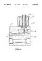
- FIG. 1is a cross sectional view of a first embodiment of the expansion valve of the present invention.
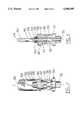
- FIG. 2is a side view of a normally closed control element of the expansion valve shown in FIG. 1.
- FIG. 3is a cross sectional side view of the control element shown in FIG. 2.
- FIG. 4is a side view of a normally open control element of an alternative embodiment of the expansion valve of the present invention.
- FIG. 5is a cross sectional view of the control element shown in FIG. 4.
- FIG. 6is a cross sectional view of the proportional solenoid actuator of the expansion valve shown in FIG. 1.
- FIG. 7is a schematic view of a heat transfer system incorporating the expansion valve of the present invention.
- the valvehas a body 12.
- the body 12includes an inlet 14 for receiving liquid refrigerant working fluid.
- the valvealso has an outlet 16 for delivering expanded working fluid to an evaporator or other exothermic heat exchanger.
- the body 12further includes a chamber 18.
- a control element 20is positioned in chamber 18. As later explained, fluid passing from inlet 14 to outlet 16 of the valve is required to pass through the control element.
- Valve 10further includes a proportional solenoid 22.
- Solenoid 22includes a movable plunger element 24.
- Plunger element 24is a low friction type plunger of the type described in U.S. Pat. No. 5,252,939, filed Sep. 25, 1992, the disclosure of which is incorporated herein by reference. As later described in detail, plunger element 24 is controlled to move downward in response to electrical signals supplied to the proportional solenoid 22.
- Body 12 of valve 10further includes a return passage 26.
- Return passage 26provides a path for working fluid from the evaporator as it returns to the compressor and the remainder of the system (see FIG. 7).
- Return passage 26provides a convenient location for sensors for detecting the character and properties of the refrigerant material leaving the evaporator.
- the expansion valveneed not include a return passage through body 12.
- Control element 20is shown in greater detail in FIGS. 2 and 3.
- Control element 20has a stem member 28 that includes an internal passage 30.
- the stem memberhas a threaded lower portion 32 for attaching to a similarly threaded opening in body 12 (not separately shown) which is in fluid communication with outlet 16.
- the stem member 28also has a hex area 34 to facilitate installation and removal of the control element from the valve.
- Stem member 28includes a cylindrical outer surface 36.
- a pair of opposed longitudinally elongated openings 38extend on outer surface 36. Openings 38 are in fluid communication with internal passage 30 through ducts 40. Ducts 40 are similarly configured to openings 38.
- Control element 20further includes a movable member 42.
- Movable member 42has a cylindrical inner surface 44 that is slightly larger in diameter than outer surface 36 of stem member 28. As a result, movable member is axially movable on stem member 28.
- Movable member 42includes an enlarged flange area 46.
- Flange area 46is in abutting relation at its lower side with a compression spring 48 as shown in FIGS. 2 and 3.
- Compression spring 48biases the movable member upward as shown in the drawings.
- Cap member 50includes a open area 52 that enables it to move downward on stem member 28 a significant distance without engaging a closed top area 54 of the stem member.
- Cap portion 50also has a rounded plunger engaging portion 56. Plunger engaging portion 56 of movable member 42 engages plunger 24 as shown in FIG. 1, as the movable member is biased against the plunger by spring 48.
- Movable member 42further includes tapered peripheral surface 58.
- Peripheral surface 58is tapered as shown in FIGS. 2 and 3 such that it is substantially thinner at a terminating edge 60.
- spring 48biases movable member 42 upward, and the peripheral surface 58 of the movable member covers openings 38 in the outer surface of stem member 28 when no downward force is applied by the plunger of the actuator.
- the control elementis biased towards the position in which openings 38 are covered, it is a normally closed element.
- other embodiments of the expansion valve of the present inventionmay have normally open control elements.
- peripheral surface 58moves to uncover openings 38 in stem member 28.
- the area outside the control element in chamber 18is in fluid communication with internal passage 30 of the control element, and outlet 16 of the valve, through ducts 40.
- the extent to which openings 38 are uncovereddetermines the flow rate of refrigerant material through the control element, and thus the flow rate from the inlet to the outlet of the expansion valve.
- the proportional solenoid 22 of the expansion valveis shown in greater detail in FIG. 6.
- the proportional solenoid 22includes an isolation tube 62.
- Isolation tube 62is generally cylindrical and has a closed top 64.
- Isolation tube 64also has a flanged bottom 66 which nests in a recess (not separately shown) in body 12.
- isolation tube 66is made of non-magnetic stainless steel material having approximately one-half inch O.D. and a 0.012 inch thick wall.
- the body 12is preferably made of non-magnetic aluminum alloy.
- a resilient seal 68is positioned under flange bottom 66 of isolation tube 62. Seal 68 serves to provide a fluid tight seal which prevents the working fluid in chamber 18 from escaping around the isolation tube through the recess.
- the isolation tubeis fixed in position as shown by fastening means (not shown).
- a flux washer 69 made of magnetic materialis positioned in the recess above flange bottom 66 of the isolation tube. The preferred form of the flux washer is sized with an opening that accepts the isolation tube, has a one inch O.D. and is 0.180 inches thick. The purpose of flux washer 69 is later described in detail.
- the isolation tube 62has a cylindrical surface 70.
- Plunger 24is movable inside an internal area 72 of the isolation tube. Internal area 72 is bounded by interior surface 70.
- plunger 24includes rollable bodies 74 that roll between the surface of plunger and the interior surface 70 of the isolation tube. Further, the isolation tube provides a radial gap in which there is no magnetic material between the plunger and the lower portion of the frame. This radial gap is approximately 0.20 inches. This construction enables plunger 24 to move with virtually no frictional resistance.
- Proportional solenoid 22further includes a wound wire coil 76 for providing an electromagnetic field when electrical power is supplied thereto.
- Coil 76is supported in a frame 78 made of magnetic material that is u-shaped in cross section.
- a cylindrical sleeve 80extends part way through the center of coil 76.
- a longitudinal gap 82extends between the bottom of sleeve 80 and the lower portion of frame 78 as shown in FIG. 6. In the preferred embodiment the length of this longitudinal gap is 0.300.
- the inside diameter of sleeve 80is slightly larger than the outside diameter of isolation tube 62.
- frame 78may be releasably attached to body 12 of the valve. This enables the coil and frame assembly to be removed from the valve without releasing any of the refrigerant working fluid 20 from the system. This makes it easier to repair or replace the coil of the solenoid actuator.
- Flux washer 69serves as a variable permeance element as its permeance varies with the distance the plunger 24 is displaced downward. As electrical power delivered to the coil of the solenoid actuator increases, the magnetic saturation at the gap 82 also increases. This causes the plunger to move downward until the force reaches an equilibrium with the biasing force of the spring of the control element.
- the position of the plunger and the movable member 42 of the control elementmay be precisely controlled. As a result, the rate of flow of working fluid through the valve is also accurately regulated.
- the proportional solenoid of the present inventionis novel in that unlike conventional solenoids the force it produces does not increase exponentially as the plunger approaches the end of its stroke. This enables the solenoid actuator to achieve a force versus stroke characteristic that enables precise and repeatable movement.
- Solenoid 22is further novel in that although it is a proportional solenoid, it is removable from the body of the valve. This facilitates repair or replacement.
- Prior art type proportional solenoidshave not generally been used in expansion valves because they could not tolerate a low permeance structure between the coil sleeve and the plunger.
- a low permeance non-magnetic isolation tubeis positioned between the magnetic sleeve and the plunger element. The presence of this low permeance tube actually enhances the ability of the plunger to move. This is believed to occur because the low permeance element maintains the plunger away from other magnetic elements and reduces resistance to movement that occurs when a magnetic element that is attracted to the plunger is immediately adjacent thereto.
- the preferred embodiment of the inventionuses an air gap to achieve a saturation area
- a non-magnetic spacer or thinned area of the sleevemay be used.
- the preferred embodimentincludes a flux washer as a variable permeance element, other embodiments may use other types of elements that exhibit increasing permeance with plunger stroke.
- plunger 24moves in a downward direction as shown in FIG. 1. Because movable member 42 is engaged with plunger 24, it likewise moves downward. This opens flow through openings 38 in the outer surface of the stem member 28. As a result, working fluid on the outside of the control element in chamber 28 flows through the control element and into the internal passage of the stem member. Because openings 38 are elongated, the further the movable member moves downward the greater the flow through the control element.
- control elementenables precise control of the flow therethrough in response to the displacement of the movable member.
- the fluidacts equally on all surfaces of the movable member. This avoids the creation of any significant forces due to flow effects. Further, the taper of peripheral surface 58 of the movable member avoids flow and pressure effects that would tend to resist movement of the movable member.
- control elementprovides precise and predictable flow control in response to the power delivered to the proportional solenoid.
- expansion valve of the present inventionmay be used to achieve more accurate control of the cooling characteristics when used in an air conditioning or other heat transfer system.
- FIG. 7A typical system in which the expansion valve 10 of the present invention may be used is shown schematically in FIG. 7.
- Liquid working fluidenters inlet 14 of the expansion valve.
- the expanded refrigerantleaves the outlet 16 and is delivered in a suitable conduit to an evaporator 84.
- the working fluidabsorbs heat as indicated by the arrows labeled Q-in, as the working fluid flows through the evaporator.
- the evaporatoris in the passenger compartment or other area to be cooled.
- a fan 86 shown schematicallyreflects that air is drawn through the evaporator to assist in heat transfer.
- Working fluid exiting the evaporatortravels in a suitable conduit back through return passage 26 of valve 10.
- the return passage through the valveprovides a suitable location for temperature and/or pressure sensors to detect the properties of the refrigerant vapor exiting the evaporator.
- the vaporized working fluidis compressed by compressor 90 and delivered in a suitable conduit to a condenser 92.
- condenser 92the working fluid loses heat as reflected by the arrows labeled Q-out.
- the condenser 92the working fluid condenses to a liquid.
- heatis transferred from the working fluid to the environment.
- Receiver-drier 88serves to remove impurities, and such receiver-driers are well known to those skilled in the art.
- Control module 96includes a processor and operates to deliver signals to the solenoid to selectively control the flow rate of refrigerant through the expansion valve.
- the control moduleis further electrically connected to sensors (not shown) which detect the characteristics of the working fluid as it leaves the evaporator, and perhaps other characteristics of the system, which enables the control module to calculate the appropriate amount of working fluid that should optimally pass through the expansion valve and to convert this amount into a signal.
- sensorsnot shown
- the preferred embodiment of the inventionincludes a proportional solenoid to move the control element which controls the rate of flow through the valve
- other types of actuatorsmay be used.
- actuatorsmay not provide as precise flow control as the proportional solenoid of the preferred embodiment, the novel control element of the present invention may still be successfully used.
- the embodiment of the valve shown in FIG. 1includes a normally closed control element 20.
- control elementsthat are normally open.
- Such a normally opened control element 98is shown in FIGS. 4 and 5.
- Control element 98is designed to be a direct replacement for control element 20, and element 98 may be substituted in expansion valve 10 without changes to the valve construction. However the actuation of the proportional solenoid by the control module would have to be changed to reflect the different character of the control element.
- Control element 98has a threaded lower portion 100 similar to threaded portion 32 of valve element 20. Also like the previously described control element, element 98 has a stem member 102 with an internal passage 104. Control element 98 also has an external hex area 106 for ease of attachment and removal.
- Control element 98further includes a cylindrical outer surface 108.
- a pair of openings 110 in surface 108are connected through ducts 112 to internal passage 104. Openings 110 are elongated longitudinally along the axis of the stem member as shown.
- Control element 98also includes a movable member 114.
- Movable member 114has a cylindrical inner surface 116 slightly larger in diameter than outer surface 108. This enables the movable member to move longitudinally on the outside of the stem member.
- the stem member 102also includes a plurality of ridges 118 in the area above openings 110 as shown in FIG. 5.
- Movable member 114further includes a downwardly tapered peripheral surface 120 which terminates at an edge 122 adjacent its lower end. Movable member 114 further includes a plunger engaging portion 124 for engaging plunger 24. A compression spring 126 biases the movable member in the upward direction as shown in FIGS. 4 and 5. Stem member 102 further includes a detent 128 for helping to center spring 126 in position.
- the plungermoves downward and the movable member 114 moves similarly against the force of spring 126.
- the movable memberpartially covers openings 110, flow through the control element is reduced. The flow is controlled by selectively moving the movable member to cover the openings to the extent desired to achieve the appropriate flow rate.
- control element 98is not significantly influenced by forces generated by the flow of the refrigerant therethrough. It also provides accurate and repeatable flow based on the position of the movable member by the proportional solenoid.
- a further advantage of the construction of the control elements of the present inventionis that fluid may flow through the valve in either direction. This avoids the need to connect the valve with particular ports as the inlet and outlet. It is also useful in heat pump applications in which refrigerant flow is reversed.
- control elements 20 and 98a pair of opposed fluid openings in the stem member are used. These openings are elongated to provide a wide range of flow rates. In other embodiments of the invention, other numbers of openings and other configurations of openings may be used depending on the range of flow rates desired.
- proportional solenoid 22 of the expansion valve of the present inventionis adapted for controlling elements such as control elements 20 and 98, the proportional solenoid may also be used in other embodiments of the invention to control other types of flow control elements.
- the new expansion valve for an air conditioning system of the present inventionachieves the above stated objectives, eliminates difficulties encountered in the use of prior devices and systems, solves problems and attains the desirable results described herein.
Landscapes
- Engineering & Computer Science (AREA)
- Physics & Mathematics (AREA)
- General Engineering & Computer Science (AREA)
- Mechanical Engineering (AREA)
- Thermal Sciences (AREA)
- Electromagnetism (AREA)
- Power Engineering (AREA)
- Magnetically Actuated Valves (AREA)
Abstract
Description
This application is a continuation of application Ser. No. 07/961,563 filed Oct. 15, 1993 now abandoned, which is a continuation-in-part of Ser. No. 07/951,259 filed Sep. 25, 1992, now U.S. Pat. No. 5,252,939, the disclosures of which are incorporated herein by reference.
This invention relates to heat transfer systems. Specifically this invention relates to an expansion valve for a vehicle air conditioning system.
Heat transfer systems, such as air conditioning systems and heat pump systems, are well known in the prior art. In such systems a working fluid which can be any one of a number of refrigerant materials is used to transfer heat from one region to another.
The working fluid typically passes through a system that includes an evaporator, a compressor, a condenser and an expansion device. Of course the system may also include other components such as an accumulator or a receiver/dryer.
In an air conditioning application the evaporator is positioned in the space to be cooled and the condenser is positioned in the area to which heat removed from the cooled space is transferred. Working fluid in the vapor state is pumped by the compressor into the condenser. In the condenser the working fluid rejects heat and condenses to a liquid.
The liquid working fluid passes from the outlet of the condenser into an expansion device. Expansion devices known in the prior art include fixed orifices, capillary tubes and expansion valves.
From the expansion device the working fluid flows to the evaporator wherein it absorbs heat and undergoes a change of phase from liquid to vapor. The refrigerant vapor then flows back to the compressor to begin another pass through the system.
The expansion device is an important element of the system. The amount of working fluid that passes through the expansion device is a controlling factor in the amount of cooling that can be achieved. However, because the temperature of both the space being cooled and the space to which heat transferred vary, the pressure and temperature of the liquid working fluid entering the expansion device also varies. This impacts the cooling capabilities of the system and affects the flow rate that must be obtained through the expansion device to achieve the optimum cooling effect. In mobile systems such as those used as air conditioning or refrigeration systems on vehicles, the properties of the working fluid delivered to the expansion device can vary widely.
Due to the variable operating conditions of vehicle heat transfer systems, fixed opening expansion devices such as orifices and capillary tubes are sometimes used to reduce cost but are not preferred. Instead, expansion valves that provide variable refrigerant flow rates are more desirable.
Prior art expansion valves have traditionally controlled flow by passing the fluid through an internal opening in the valve and employing a movable restricting body or other element in close proximity to the opening. Moving the restricting body closer to the opening reduces flow. Conversely, moving the restricting body away from the opening increases flow through the valve.
In prior art expansion valves the position of the restricting body has been controlled by an actuator. A common actuator is a diaphragm type which is mounted on the valve. The actuator opens or closes flow through the expansion valve in response to fluid pressure both inside the valve and from a control source.
The control source fluid pressure for moving the restricting body is delivered from a sealed bulb which holds a carefully determined fluid charge. The bulb is commonly mounted adjacent to the outlet line from the evaporator. When the temperature of the working fluid exiting the space to be cooled begins to increase, the temperature of the bulb also increases. As the pressure of the fluid inside the bulb increases it moves the diaphragm and the blocking body inside the expansion valve to increase the flow rate of working fluid to the evaporator. The increased flow of working fluid provides more cooling and eventually the temperature at the outlet of the evaporator drops. When this occurs the pressure inside the bulb falls, moving the diaphragm and the restricting body to reduce the flow rate of working fluid through the valve. The charge in the bulb is contrived to have a small amount of superheat in the refrigerant leaving the evaporator.
A problem with this type of prior art actuator is that the expansion device is constantly seeking the optimum rate of flow. The response time renders the expansion device unable to react properly to changing conditions. This is particularly a problem in vehicle applications where changes in cooling loads and variations in refrigerant properties are common. As a result, the accuracy of control is also less than optimum.
Others have previously used electrically controlled expansion valves to control the flow of working fluid in a heat transfer system. These systems typically use valves that are either fully open or fully closed. The valve is periodically opened and closed for controlled time periods to achieve an overall average flow rate that is designed to handle the heat transfer load at the evaporator.
A significant problem with such pulse width modulated expansion valves is that they must open and close very frequently. This causes rapid wear of the valve components. The opening and closing action also often causes "hammering" in the system. The vibration associated with hammering may cause fatigue and premature failure of the valve and the connected tubing. It also makes accurate pressure measurement impossible.
The control elements used in prior art expansion valves for controlling or regulating the flow of working fluid also have drawbacks. The valves that meter flow must be made to deal with the static and dynamic pressure effects created by the working fluid as it passes through the valve. In some designs efforts are made to use the pressure of the working fluid to develop balancing forces. These balancing forces enable more precise movement of the restricting body or other control element. This is intended to enable more precise control of the flow rate.
The problem with attempts to design expansion valves that make use of such balancing forces is that the forces vary substantially with the fluid conditions and the flow rate. As a result it has been difficult to produce an expansion valve that provides accurate control of fluid flow over a wide range of operating conditions.
Thus there exists a need for an expansion valve for heat transfer systems that provides accurate flow control for the working fluid under a wide range of operating and flow conditions.
It is an object of the present invention to provide an expansion valve that accurately controls the flow of working fluid therethrough.
It is a further object of the present invention to provide an expansion valve that includes a control element that minimizes the influence of flow and pressure effects.
It is a further object of the present invention to provide an expansion valve that includes a proportional solenoid actuator that accurately controls flow through the control element.
It is a further object of the present invention to provide an expansion valve that minimizes vibration and has a long useful life.
It is a further object of the present invention to provide an expansion valve that has few moving parts, is economical to manufacture and is readily repaired.
It is a further object of the present invention to provide an expansion valve that can be operated with flow in either direction.
Further objects of the present invention will be made apparent in the following Best Modes for Carrying Out Invention and the appended claims.
The foregoing objects are accomplished in the preferred embodiment of the invention by an expansion valve for controlling the flow of refrigerant material flowing to an evaporator of a heat transfer system, such as a vehicle air conditioning system. The valve has a body with an inlet for receiving liquid refrigerant material and an outlet for delivering expanded refrigerant material.
The expansion valve includes a control element between the inlet and the outlet for controlling the flow rate of refrigerant material through the valve. The control element has a cylindrical stem member with an internal passage. The stem member has a cylindrical outer surface. The outer surface preferably includes a pair of opposed longitudinally elongated openings.
The control element further includes a movable member mounted for movement on the outside of the stem member. The movable member is movable through a range positions between a first position wherein the valve is fully open and a second position wherein the valve is fully closed.
In a first embodiment, the control element is configured to be a normally closed element. However in other embodiments the valve may be configured to be normally open. The control element is not significantly influenced by flow or pressure forces, and is thereby enabled to provide an accurate rate of flow depending on the position of the movable member. It also accomodates flow in either direction through the element.
The movable member of the control element is positioned by a proportional solenoid actuator. The proportional solenoid actuator is constructed with a novel low friction plunger as described in U.S. Pat. No. 5,252,939 filed Sep. 25, 1992, the disclosure of which is incorporated herein by reference.
The proportional solenoid actuator also includes a novel removable coil design that facilitates repair or replacement of the actuator. The solenoid actuator also includes a novel magnetic flux circuit that includes a low permeance, non-magnetic isolation tube in series with a variable permeance element. This construction provides a proportional solenoid that achieves accurate positioning of the movable member of the control element in response to electrical signals delivered to the proportional solenoid actuator.
Accurately positioning the control element of the valve through movement of the proportional actuator, enables accurate flow control through the expansion valve and precise control of the cooling effects of the system in which the expansion valve is used.
FIG. 1 is a cross sectional view of a first embodiment of the expansion valve of the present invention.
FIG. 2 is a side view of a normally closed control element of the expansion valve shown in FIG. 1.
FIG. 3 is a cross sectional side view of the control element shown in FIG. 2.
FIG. 4 is a side view of a normally open control element of an alternative embodiment of the expansion valve of the present invention.
FIG. 5 is a cross sectional view of the control element shown in FIG. 4.
FIG. 6 is a cross sectional view of the proportional solenoid actuator of the expansion valve shown in FIG. 1.
FIG. 7 is a schematic view of a heat transfer system incorporating the expansion valve of the present invention.
Referring now to the drawings and particularly to FIG. 1, there is shown therein a first embodiment of the expansion valve of the present invention generally indicated 10. The valve has abody 12. Thebody 12 includes aninlet 14 for receiving liquid refrigerant working fluid. The valve also has anoutlet 16 for delivering expanded working fluid to an evaporator or other exothermic heat exchanger.
Thebody 12 further includes achamber 18. Acontrol element 20 is positioned inchamber 18. As later explained, fluid passing frominlet 14 tooutlet 16 of the valve is required to pass through the control element.
The upper surface offlange area 46 supports acap portion 50 of the movable member.Cap member 50 includes aopen area 52 that enables it to move downward on stem member 28 a significant distance without engaging a closedtop area 54 of the stem member.Cap portion 50 also has a roundedplunger engaging portion 56.Plunger engaging portion 56 ofmovable member 42 engagesplunger 24 as shown in FIG. 1, as the movable member is biased against the plunger byspring 48.
As shown in FIGS. 2 and 3,spring 48 biasesmovable member 42 upward, and theperipheral surface 58 of the movable member coversopenings 38 in the outer surface ofstem member 28 when no downward force is applied by the plunger of the actuator. As the control element is biased towards the position in whichopenings 38 are covered, it is a normally closed element. As discussed later in conjunction with the description of the embodiment of the control element shown in FIGS. 4 and 5, other embodiments of the expansion valve of the present invention may have normally open control elements.
Whenmovable member 42 is moved in a direction downward as shown in FIGS. 2 and 3,peripheral surface 58 moves to uncoveropenings 38 instem member 28. As a result, the area outside the control element inchamber 18 is in fluid communication withinternal passage 30 of the control element, andoutlet 16 of the valve, throughducts 40. The extent to whichopenings 38 are uncovered determines the flow rate of refrigerant material through the control element, and thus the flow rate from the inlet to the outlet of the expansion valve.
Theproportional solenoid 22 of the expansion valve is shown in greater detail in FIG. 6. Theproportional solenoid 22 includes anisolation tube 62.Isolation tube 62 is generally cylindrical and has a closedtop 64.Isolation tube 64 also has a flanged bottom 66 which nests in a recess (not separately shown) inbody 12. In the preferred form of theinvention isolation tube 66 is made of non-magnetic stainless steel material having approximately one-half inch O.D. and a 0.012 inch thick wall. Thebody 12 is preferably made of non-magnetic aluminum alloy.
Aresilient seal 68 is positioned underflange bottom 66 ofisolation tube 62.Seal 68 serves to provide a fluid tight seal which prevents the working fluid inchamber 18 from escaping around the isolation tube through the recess. The isolation tube is fixed in position as shown by fastening means (not shown). Aflux washer 69 made of magnetic material is positioned in the recess aboveflange bottom 66 of the isolation tube. The preferred form of the flux washer is sized with an opening that accepts the isolation tube, has a one inch O.D. and is 0.180 inches thick. The purpose offlux washer 69 is later described in detail.
Theisolation tube 62 has acylindrical surface 70.Plunger 24 is movable inside aninternal area 72 of the isolation tube.Internal area 72 is bounded byinterior surface 70. As described in U.S. Pat. No. 5,252,939,plunger 24 includesrollable bodies 74 that roll between the surface of plunger and theinterior surface 70 of the isolation tube. Further, the isolation tube provides a radial gap in which there is no magnetic material between the plunger and the lower portion of the frame. This radial gap is approximately 0.20 inches. This construction enablesplunger 24 to move with virtually no frictional resistance.
In the preferred embodiment of the invention the inside diameter ofsleeve 80 is slightly larger than the outside diameter ofisolation tube 62. In addition, in the preferred embodiment,frame 78 may be releasably attached tobody 12 of the valve. This enables the coil and frame assembly to be removed from the valve without releasing any of the refrigerant workingfluid 20 from the system. This makes it easier to repair or replace the coil of the solenoid actuator.
An operation of the expansion valve, when no electrical power is applied tocoil 76, thespring 48 ofcontrol element 20 biases plunger 24 upward to the position shown in FIGS. 1 and 6. Supplying power tocoil 76 creates an electromagnetic field. The electromagnetic field produces a flux circuit aboutsolenoid 22. The flux circuit extends through thesleeve 80, theframe 78 and theflux washer 69. However,gap 82 causes magnetic saturation in the area of the gap.
The plunger functions as a member for completing the magnetic flux circuit.Flux washer 69 serves as a variable permeance element as its permeance varies with the distance theplunger 24 is displaced downward. As electrical power delivered to the coil of the solenoid actuator increases, the magnetic saturation at thegap 82 also increases. This causes the plunger to move downward until the force reaches an equilibrium with the biasing force of the spring of the control element.
By varying the amount of power delivered to the coil of the proportional solenoid, the position of the plunger and themovable member 42 of the control element may be precisely controlled. As a result, the rate of flow of working fluid through the valve is also accurately regulated.
The proportional solenoid of the present invention is novel in that unlike conventional solenoids the force it produces does not increase exponentially as the plunger approaches the end of its stroke. This enables the solenoid actuator to achieve a force versus stroke characteristic that enables precise and repeatable movement.
It will be understood by those skilled in the art, that although the preferred embodiment of the invention uses an air gap to achieve a saturation area, in other embodiments a non-magnetic spacer or thinned area of the sleeve may be used. Likewise, although the preferred embodiment includes a flux washer as a variable permeance element, other embodiments may use other types of elements that exhibit increasing permeance with plunger stroke.
In operation of the proportional solenoid, as greater electrical power is delivered tocoil 76plunger 24 moves in a downward direction as shown in FIG. 1. Becausemovable member 42 is engaged withplunger 24, it likewise moves downward. This opens flow throughopenings 38 in the outer surface of thestem member 28. As a result, working fluid on the outside of the control element inchamber 28 flows through the control element and into the internal passage of the stem member. Becauseopenings 38 are elongated, the further the movable member moves downward the greater the flow through the control element.
The configuration of the control element enables precise control of the flow therethrough in response to the displacement of the movable member. In addition, because the movement of the movable member to open and close the control element is perpendicular to the direction of fluid flow, the fluid acts equally on all surfaces of the movable member. This avoids the creation of any significant forces due to flow effects. Further, the taper ofperipheral surface 58 of the movable member avoids flow and pressure effects that would tend to resist movement of the movable member.
The control element provides precise and predictable flow control in response to the power delivered to the proportional solenoid. As a result, the expansion valve of the present invention may be used to achieve more accurate control of the cooling characteristics when used in an air conditioning or other heat transfer system.
A typical system in which theexpansion valve 10 of the present invention may be used is shown schematically in FIG. 7. Liquid working fluid entersinlet 14 of the expansion valve. The expanded refrigerant leaves theoutlet 16 and is delivered in a suitable conduit to anevaporator 84. The working fluid absorbs heat as indicated by the arrows labeled Q-in, as the working fluid flows through the evaporator. Of course in the preferred form of the invention, which is an air conditioning system for a vehicle, the evaporator is in the passenger compartment or other area to be cooled. A fan 86 shown schematically reflects that air is drawn through the evaporator to assist in heat transfer.
Working fluid exiting the evaporator travels in a suitable conduit back throughreturn passage 26 ofvalve 10. As previously discussed, the return passage through the valve provides a suitable location for temperature and/or pressure sensors to detect the properties of the refrigerant vapor exiting the evaporator.
The vaporized working fluid is compressed bycompressor 90 and delivered in a suitable conduit to acondenser 92. Incondenser 92 the working fluid loses heat as reflected by the arrows labeled Q-out. In thecondenser 92 the working fluid condenses to a liquid. Afan 94 shown schematically aids in transferring heat from the working fluid as it passes through the condenser. In the preferred embodiment of the invention, which is an air conditioning system for a vehicle, heat is transferred from the working fluid to the environment.
From the condenser the liquefied working fluid is returned to theinlet 14 of the expansion valve, after first passing through a receiver-drier 88. Receiver-drier 88 serves to remove impurities, and such receiver-driers are well known to those skilled in the art.
Theproportional solenoid 22 is actuated by an electronic control module shown schematically as 96.Control module 96 includes a processor and operates to deliver signals to the solenoid to selectively control the flow rate of refrigerant through the expansion valve. The control module is further electrically connected to sensors (not shown) which detect the characteristics of the working fluid as it leaves the evaporator, and perhaps other characteristics of the system, which enables the control module to calculate the appropriate amount of working fluid that should optimally pass through the expansion valve and to convert this amount into a signal. Those skilled in the art may devise numerous ways of sensing the parameters desired to be used to control the flow rate through the expansion valve and for thecontrol module 96 to properly actuate the valve to provide the desired flow.
While the preferred embodiment of the invention includes a proportional solenoid to move the control element which controls the rate of flow through the valve, in other embodiments other types of actuators may be used. Although such actuators may not provide as precise flow control as the proportional solenoid of the preferred embodiment, the novel control element of the present invention may still be successfully used.
The embodiment of the valve shown in FIG. 1 includes a normally closedcontrol element 20. However other embodiments of the invention may include control elements that are normally open. Such a normally openedcontrol element 98 is shown in FIGS. 4 and 5.Control element 98 is designed to be a direct replacement forcontrol element 20, andelement 98 may be substituted inexpansion valve 10 without changes to the valve construction. However the actuation of the proportional solenoid by the control module would have to be changed to reflect the different character of the control element.
In operation of an expansion valve that includescontrol element 98, full flow is achieved whenmovable member 114 is disposed in its fully upward position. This occurs when no power is delivered to the proportional solenoid andplunger 24 is disposed fully upward as shown in FIG. 1.
As electrical power to the coil of the solenoid is increased, the plunger moves downward and themovable member 114 moves similarly against the force ofspring 126. As the movable member partially coversopenings 110, flow through the control element is reduced. The flow is controlled by selectively moving the movable member to cover the openings to the extent desired to achieve the appropriate flow rate.
Likecontrol element 20,control element 98 is not significantly influenced by forces generated by the flow of the refrigerant therethrough. It also provides accurate and repeatable flow based on the position of the movable member by the proportional solenoid.
A further advantage of the construction of the control elements of the present invention is that fluid may flow through the valve in either direction. This avoids the need to connect the valve with particular ports as the inlet and outlet. It is also useful in heat pump applications in which refrigerant flow is reversed.
In the preferred construction ofcontrol elements
It will be understood by those skilled in the art that although theproportional solenoid 22 of the expansion valve of the present invention is adapted for controlling elements such ascontrol elements
Thus, the new expansion valve for an air conditioning system of the present invention achieves the above stated objectives, eliminates difficulties encountered in the use of prior devices and systems, solves problems and attains the desirable results described herein.
In the foregoing description certain terms have been used for brevity, clarity and understanding. However, no unnecessary limitations are to be implied therefrom because such terms are for descriptive purposes and are intended to be broadly construed. Moreover, the descriptions and illustrations given are by way of examples and the invention is not limited to the exact details shown or described.
Having described the features, discoveries and principles of the invention, the manner in which it is constructed and utilized, and the advantages and useful results obtained; the new and useful methods, structures, devices, elements, arrangements, parts, combinations, systems, equipment, operations and relationships are set forth in the appended claims.
Claims (22)
1. A valve for controlling flow of fluid material comprising:
a body, said body including an inlet port and an outlet port;
a control element positioned fluidly intermediate of said inlet port and said outlet port in said body;
said control element comprising:
a stem member, said stem member including an internal passage, said internal passage connected to one of said ports of said valve; said stem member further having a generally cylindrical outer surface, said outer surface including a plurality of similar openings therein, said openings angularly spaced about said outer surface, said openings in fluid communication with said internal passage;
a movable member mounted for movement on said outer surface of said stem member, said movable member having an outer peripheral surface and an inner surface adjacent said outer surface of said stem, said peripheral surface tapered to a substantially thinner terminating edge adjacent said openings, said movable member disposed for movement within a range of positions between a first position wherein said edge is disposed from said openings whereby flow through said openings is enabled, intermediate positions wherein said edge is laterally adjacent said openings to regulate fluid flow therethrough, and a second position wherein said tapered peripheral surface is in substantially blocking relation with said openings.
2. The valve according to claim 1 wherein said movable member of said control element is movable longitudinally on said stem member.
3. The valve according to claim 1 wherein said openings are each in fluid communication with said internal passage of said stem member through a duct, said ducts extending substantially radially outward.
4. The valve according to claim 1 wherein said inner surface of said movable member is always slightly disposed radially from said outer surface of said stem member.
5. The valve according to claim 1 wherein said openings are equally angularly spaced about said outer surface of said stem member.
6. The valve according to claim 1 and further comprising biasing means for biasing said movable member to either said first position or said second position.
7. The valve according to claim 1 and further comprising an electrical solenoid in connection with said movable member.
8. The valve according to claim 7 wherein said solenoid includes a plunger comprised of magnetic material, said plunger selectively movable in the longitudinal direction, and wherein said movable member of said control element includes a plunger engaging portion for engaging said plunger longitudinally away from said openings in said stem member.
9. The valve according to claim 8 and further comprising biasing means for biasing said movable member of said control element to the first position, and wherein said plunger is movable in engagement with said movable member to overcome said biasing force, and wherein said peripheral surface of said movable member is disposed longitudinally intermediate of said openings and said plunger when said movable member is in the first position.
10. The valve according to claim 8 and further comprising biasing means for biasing said movable member to the second position, and wherein said plunger is movable in engagement with said movable member to overcome said biasing means, and said peripheral surface is disposed longitudinally intermediate of said plunger and said openings when said movable member is in the second position.
11. The expansion valve according to claim 9 wherein said stem member has a plurality of ducts and openings equally spaced angularly about said stem member, and wherein said openings and ducts are elongated in the longitudinal direction.
12. The expansion valve according to claim 10 wherein said stem member includes a plurality of ducts and openings equally spaced angularly about and wherein said stem member, said openings and ducts are elongated in the longitudinal direction.
13. The valve of claim 1 wherein said edge is exposed to substantial fluid flow when positioned laterally adjacent said openings, said valve operating to proportionally control fluid flow through said control element based on proportional control of said edge position adjacent said openings.
14. The valve of claim 1 wherein said edge and inner surface partially block fluid flow through said openings to regulate fluid flow therethrough, there being a substantial pressure drop between said inlet port and said outlet port, said tapered peripheral portion and edge substantially reducing fluid flow forces acting on said movable member, thereby improving control of movement of said movable member at said intermediate positions.
15. The valve of claim 7 wherein said solenoid comprises a proportional solenoid.
16. A valve for controlling the flow of fluid material therethrough comprising:
a body, said body including an inlet port and an outlet port;
a control element positioned fluidly intermediate of said inlet port and said outlet port of said body, whereby said fluid material passes through said control element;
said control element comprising:
a stem member, said stem member including an internal passage, said internal passage connected to one of said ports of said valve;
said stem member further having a generally cylindrical outer surface, said outer surface including at least one opening therethrough, said opening in fluid communication with said internal passage;
a movable member disposed for proportional movement on said outer surface of said stem member, said movable member having a tapered outer peripheral surface adjacent said opening, said peripheral surface tapered to a substantially thinner edge adjacent said outer surface of said stem, said movable member movable through a range of positions between a first position wherein said edge of said movable member is disposed from said opening whereby flow through said opening is enabled, intermediate positions wherein said edge partially covers said opening to regulate flow of fluid therethrough, and a second position wherein said tapered peripheral surface of said movable member is in substantially blocking overlying relation with said opening.
17. The valve according to claim 16 wherein said stem includes a plurality of openings equally angularly spaced about said outer surface.
18. The valve according to claim 16 wherein said peripheral surface is a conically tapered surface.
19. The valve according to claim 18 wherein said movable member has an annular inner surface interiorly of said peripheral surface, said inner surface always slightly radially disposed from said outer surface of said stem.
20. A valve for controlling the flow of fluid material therethrough comprising:
a body, said body including an inlet port and an outlet port;
a control element positioned fluidly intermediate of said inlet port and said outlet port of said body, whereby said fluid material passes through said control element;
said control element comprising:
a stem member, said stem member including an internal passage, said internal passage connected to one of said ports of said valve;
said stem member further having a generally cylindrical outer surface, said outer surface including at least one opening therethrough, said opening in fluid communication with said internal passage;
a sleeve member mounted on said outer surface of said stem member to permit relative movement between said sleeve member and said stem member, said sleeve member having a tapered outer peripheral surface adjacent said opening, said peripheral surface tapered to a subsantially edge adjacent said outer surface of said stem, said sleeve member adapted for relative movement within a range of positions between a first position wherein said edge of said sleeve member is disposed from said opening whereby flow through said opening is enabled, intermediate positions for adjusting fluid flow through said opening, and a second position wherein said tapered peripheral surface of said movable member is in substantially blocking overlying relation of said opening.
21. A valve for controlling the flow of fluid material therethrough comprising:
a body, said body including an inlet port and an outlet port;
a control element positioned fluidly intermediate of said inlet port and said outlet port of said body, whereby said fluid material passes through said control element;
said control element comprising:
a stem member, said stem member including an internal passage, said internal passage connected to one of said ports of said valve;
said stem member further having a generally cylindrical outer surface, said outer surface including at least one opening therethrough, said opening in fluid communication with said internal passage;
a movable member disposed for movement on said outer surface of said stem member, said movable member having a conically tapered outer peripheral surface adjacent said opening, said stem member extending axially through said peripheral surface and wherein a terminating edge of said peripheral surface is adjacent said outer surface of said stem, and means for permitting controlled proportional movement of said movable member within a range of positions between a first position wherein said edge of said movable member is disposed from said opening whereby flow through said opening is enabled, and a second position wherein said tapered peripheral surface of said movable member is in substantially blocking overlying relation with said opening.
22. A valve for controlling the flow of fluid material therethrough comprising:
a body, said body including an inlet port and an outlet port;
a control element positioned fluidly intermediate of said inlet port and said outlet port of said body, whereby said fluid material passes through said control element;
said control element comprising:
a stem member, said stem member including an internal passage connected to one of said ports of said valve;
said stem member further having a generally cylindrical outer surface, said outer surface including at least one opening therethrough, said opening in fluid communication with said internal passage;
a movable member mounted for relative movement on said outer surface of said stem member, said movable member having a peripheral surface tapered to an edge adjacent to said opening, said peripheral surface adjacent said opening having a contour wherein flow and pressure effect forces resulting from fluid flowing through said opening and resisting movement of said movable member are avoided;
said movable member disposed for movement through a range of positions between a first position wherein said edge of said movable member is disposed from said opening whereby flow through said opening is enabled, intermediate positions wherein said edge is exposed to fluid flow and regulates fluid flow through said opening, and a second position wherein said tapered peripheral surface of said movable member is in substantially blocking overlying relation with said opening.
Priority Applications (1)
| Application Number | Priority Date | Filing Date | Title |
|---|---|---|---|
| US08/154,674US5460349A (en) | 1992-09-25 | 1993-11-18 | Expansion valve control element for air conditioning system |
Applications Claiming Priority (3)
| Application Number | Priority Date | Filing Date | Title |
|---|---|---|---|
| US07/951,259US5252939A (en) | 1992-09-25 | 1992-09-25 | Low friction solenoid actuator and valve |
| US96156392A | 1992-10-15 | 1992-10-15 | |
| US08/154,674US5460349A (en) | 1992-09-25 | 1993-11-18 | Expansion valve control element for air conditioning system |
Related Parent Applications (1)
| Application Number | Title | Priority Date | Filing Date |
|---|---|---|---|
| US96156392AContinuation | 1992-09-25 | 1992-10-15 |
Publications (1)
| Publication Number | Publication Date |
|---|---|
| US5460349Atrue US5460349A (en) | 1995-10-24 |
Family
ID=27130311
Family Applications (1)
| Application Number | Title | Priority Date | Filing Date |
|---|---|---|---|
| US08/154,674Expired - LifetimeUS5460349A (en) | 1992-09-25 | 1993-11-18 | Expansion valve control element for air conditioning system |
Country Status (1)
| Country | Link |
|---|---|
| US (1) | US5460349A (en) |
Cited By (17)
| Publication number | Priority date | Publication date | Assignee | Title |
|---|---|---|---|---|
| US5689965A (en)* | 1993-01-11 | 1997-11-25 | Hitachi, Ltd. | Air conditioner |
| WO1998014739A1 (en) | 1996-09-30 | 1998-04-09 | Parker-Hannifin Corporation | Mass flow control of a working fluid |
| US6158466A (en)* | 1999-01-14 | 2000-12-12 | Parker-Hannifin Corporation | Four-way flow reversing valve for reversible refrigeration cycles |
| EP1195546A1 (en)* | 2000-10-03 | 2002-04-10 | Kabushiki Kaisha Kobe Seiko Sho | Valve device |
| US6460354B2 (en) | 2000-11-30 | 2002-10-08 | Parker-Hannifin Corporation | Method and apparatus for detecting low refrigerant charge |
| EP1316750A1 (en)* | 2001-12-03 | 2003-06-04 | TGK Co., Ltd. | Proportional solenoid valve |
| US20060136659A1 (en)* | 2004-12-21 | 2006-06-22 | Sanjeev Jain | Processor having content addressable memory with command ordering |
| US20060143373A1 (en)* | 2004-12-28 | 2006-06-29 | Sanjeev Jain | Processor having content addressable memory for block-based queue structures |
| US7277990B2 (en) | 2004-09-30 | 2007-10-02 | Sanjeev Jain | Method and apparatus providing efficient queue descriptor memory access |
| CN100425930C (en)* | 2005-07-28 | 2008-10-15 | 株式会社电装 | Temperature-type expansion valve |
| US7555630B2 (en) | 2004-12-21 | 2009-06-30 | Intel Corporation | Method and apparatus to provide efficient communication between multi-threaded processing elements in a processor unit |
| US20130085687A1 (en)* | 2010-06-09 | 2013-04-04 | Vladimir Danov | Method and device for determining the flow rate of magnetic or ferromagnetic particles and use of said method and device |
| EP2952794A1 (en) | 2014-06-04 | 2015-12-09 | Danfoss A/S | Solenoid valve |
| CN105674637A (en)* | 2016-01-13 | 2016-06-15 | 同济大学 | Refrigerating fluid expansion valve based on differential pressure self-regulation |
| US9627121B2 (en)* | 2014-05-28 | 2017-04-18 | Flextronics Automotive, Inc. | Solenoid robust against misalignment of pole piece and flux sleeve |
| CN106662371A (en)* | 2014-08-21 | 2017-05-10 | 丹佛斯有限公司 | A pulsation damper for a vapour compression system |
| FR3120413A1 (en)* | 2021-03-08 | 2022-09-09 | Schrader | EXPANSION VALVE COMPRISING A MOVABLE SLIDE |
Citations (32)
| Publication number | Priority date | Publication date | Assignee | Title |
|---|---|---|---|---|
| US2663307A (en)* | 1949-07-16 | 1953-12-22 | American Iron And Machine Work | Washout sub for well packers |
| US3089627A (en)* | 1959-04-17 | 1963-05-14 | Lippig Alfons | Closure means for containers |
| US3136336A (en)* | 1960-08-25 | 1964-06-09 | Powers Regulator Co | Valve |
| DE1254923B (en)* | 1966-09-09 | 1967-11-23 | S P R L Robinetterie Van Baste | Water pipe valve |
| DE2011660A1 (en)* | 1970-03-12 | 1971-09-30 | Apa Kg Bauder Otto | STOPCOCK |
| US4067541A (en)* | 1976-03-26 | 1978-01-10 | The Toro Company | Water valve operating solenoid |
| US4339109A (en)* | 1979-04-04 | 1982-07-13 | Aisin Seiki Kabushiki Kaisha | Electromagnetically operated valve unit |
| US4362027A (en)* | 1977-12-30 | 1982-12-07 | Sporlan Valve Company | Refrigeration control system for modulating electrically-operated expansion valves |
| US4419642A (en)* | 1982-01-28 | 1983-12-06 | Deere & Company | Solenoid with saturable element |
| US4425767A (en)* | 1979-10-01 | 1984-01-17 | Sporlan Valve Company | Refrigeration control system for modulating electrically-operated expansion valves |
| US4437645A (en)* | 1981-02-20 | 1984-03-20 | Aisin Seiki Kabushiki Kaisha | Electrically driven flow control valve assembly |
| US4448038A (en)* | 1979-10-01 | 1984-05-15 | Sporlan Valve Company | Refrigeration control system for modulating electrically-operated expansion valves |
| US4452424A (en)* | 1979-01-19 | 1984-06-05 | Aisin Seiki Kabushiki Kaisha | Electromagnetic linear control valve |
| US4459819A (en)* | 1982-03-05 | 1984-07-17 | Emerson Electric Co. | Pulse controlled expansion valve and method |
| US4483369A (en)* | 1981-05-02 | 1984-11-20 | Aisin Seiki Kabushiki Kaisha | Linear motor-actuated flow control valve |
| US4523436A (en)* | 1983-12-22 | 1985-06-18 | Carrier Corporation | Incrementally adjustable electronic expansion valve |
| US4530374A (en)* | 1981-05-02 | 1985-07-23 | Aisin Seiki Kabushiki Kaisha | Linear motor-actuated flow control valve |
| US4548047A (en)* | 1981-11-11 | 1985-10-22 | Hitachi, Ltd. | Expansion valve |
| US4614327A (en)* | 1984-11-12 | 1986-09-30 | Danfoss A/S | Valve for volatile liquids, particularly expansion valve for refrigeration plants |
| US4632358A (en)* | 1984-07-17 | 1986-12-30 | Eaton Corporation | Automotive air conditioning system including electrically operated expansion valve |
| US4638973A (en)* | 1985-11-14 | 1987-01-27 | Eaton Corporation | Inline solenoid operated slide valve |
| US4697608A (en)* | 1986-04-30 | 1987-10-06 | Eaton Corporation | Electromagnetic valve assembly |
| US4750704A (en)* | 1983-12-21 | 1988-06-14 | Robert W. Brundage | Solenoid controlled fluid flow valve |
| US4817914A (en)* | 1987-12-23 | 1989-04-04 | Eaton Corporation | Electromagnetic valve assembly |
| US4892285A (en)* | 1988-04-29 | 1990-01-09 | Eaton Corporation | Modulated electrically operated refrigerant expansion valve |
| US4896860A (en)* | 1989-05-08 | 1990-01-30 | Eaton Corporation | Electrically operated refrigerant valve |
| US4954799A (en)* | 1989-06-02 | 1990-09-04 | Puritan-Bennett Corporation | Proportional electropneumatic solenoid-controlled valve |
| US4988074A (en)* | 1988-05-17 | 1991-01-29 | Hi-Ram, Inc. | Proportional variable force solenoid control valve |
| US5046702A (en)* | 1987-03-14 | 1991-09-10 | Kabushiki Kaisha Kambayashi Seisakujo | Solenoid device |
| US5067687A (en)* | 1990-02-08 | 1991-11-26 | Applied Power Inc. | Proportional pressure control valve |
| US5139227A (en)* | 1990-06-04 | 1992-08-18 | Mitsubishi Denki K.K. | Proportional flow control valve |
| EP0538926A1 (en)* | 1991-10-21 | 1993-04-28 | Carlo Musso | Device for metering high viscosity substances |
- 1993
- 1993-11-18USUS08/154,674patent/US5460349A/ennot_activeExpired - Lifetime
Patent Citations (33)
| Publication number | Priority date | Publication date | Assignee | Title |
|---|---|---|---|---|
| US2663307A (en)* | 1949-07-16 | 1953-12-22 | American Iron And Machine Work | Washout sub for well packers |
| US3089627A (en)* | 1959-04-17 | 1963-05-14 | Lippig Alfons | Closure means for containers |
| US3136336A (en)* | 1960-08-25 | 1964-06-09 | Powers Regulator Co | Valve |
| DE1254923B (en)* | 1966-09-09 | 1967-11-23 | S P R L Robinetterie Van Baste | Water pipe valve |
| DE2011660A1 (en)* | 1970-03-12 | 1971-09-30 | Apa Kg Bauder Otto | STOPCOCK |
| US4067541A (en)* | 1976-03-26 | 1978-01-10 | The Toro Company | Water valve operating solenoid |
| US4362027A (en)* | 1977-12-30 | 1982-12-07 | Sporlan Valve Company | Refrigeration control system for modulating electrically-operated expansion valves |
| US4452424A (en)* | 1979-01-19 | 1984-06-05 | Aisin Seiki Kabushiki Kaisha | Electromagnetic linear control valve |
| US4339109A (en)* | 1979-04-04 | 1982-07-13 | Aisin Seiki Kabushiki Kaisha | Electromagnetically operated valve unit |
| US4425767A (en)* | 1979-10-01 | 1984-01-17 | Sporlan Valve Company | Refrigeration control system for modulating electrically-operated expansion valves |
| US4448038A (en)* | 1979-10-01 | 1984-05-15 | Sporlan Valve Company | Refrigeration control system for modulating electrically-operated expansion valves |
| US4437645A (en)* | 1981-02-20 | 1984-03-20 | Aisin Seiki Kabushiki Kaisha | Electrically driven flow control valve assembly |
| US4483369A (en)* | 1981-05-02 | 1984-11-20 | Aisin Seiki Kabushiki Kaisha | Linear motor-actuated flow control valve |
| US4530374A (en)* | 1981-05-02 | 1985-07-23 | Aisin Seiki Kabushiki Kaisha | Linear motor-actuated flow control valve |
| US4548047A (en)* | 1981-11-11 | 1985-10-22 | Hitachi, Ltd. | Expansion valve |
| US4419642A (en)* | 1982-01-28 | 1983-12-06 | Deere & Company | Solenoid with saturable element |
| US4459819A (en)* | 1982-03-05 | 1984-07-17 | Emerson Electric Co. | Pulse controlled expansion valve and method |
| US4750704A (en)* | 1983-12-21 | 1988-06-14 | Robert W. Brundage | Solenoid controlled fluid flow valve |
| EP0147357A2 (en)* | 1983-12-22 | 1985-07-03 | Carrier Corporation | Refrigeration system and incrementally adjustable electronic expansion valve |
| US4523436A (en)* | 1983-12-22 | 1985-06-18 | Carrier Corporation | Incrementally adjustable electronic expansion valve |
| US4632358A (en)* | 1984-07-17 | 1986-12-30 | Eaton Corporation | Automotive air conditioning system including electrically operated expansion valve |
| US4614327A (en)* | 1984-11-12 | 1986-09-30 | Danfoss A/S | Valve for volatile liquids, particularly expansion valve for refrigeration plants |
| US4638973A (en)* | 1985-11-14 | 1987-01-27 | Eaton Corporation | Inline solenoid operated slide valve |
| US4697608A (en)* | 1986-04-30 | 1987-10-06 | Eaton Corporation | Electromagnetic valve assembly |
| US5046702A (en)* | 1987-03-14 | 1991-09-10 | Kabushiki Kaisha Kambayashi Seisakujo | Solenoid device |
| US4817914A (en)* | 1987-12-23 | 1989-04-04 | Eaton Corporation | Electromagnetic valve assembly |
| US4892285A (en)* | 1988-04-29 | 1990-01-09 | Eaton Corporation | Modulated electrically operated refrigerant expansion valve |
| US4988074A (en)* | 1988-05-17 | 1991-01-29 | Hi-Ram, Inc. | Proportional variable force solenoid control valve |
| US4896860A (en)* | 1989-05-08 | 1990-01-30 | Eaton Corporation | Electrically operated refrigerant valve |
| US4954799A (en)* | 1989-06-02 | 1990-09-04 | Puritan-Bennett Corporation | Proportional electropneumatic solenoid-controlled valve |
| US5067687A (en)* | 1990-02-08 | 1991-11-26 | Applied Power Inc. | Proportional pressure control valve |
| US5139227A (en)* | 1990-06-04 | 1992-08-18 | Mitsubishi Denki K.K. | Proportional flow control valve |
| EP0538926A1 (en)* | 1991-10-21 | 1993-04-28 | Carlo Musso | Device for metering high viscosity substances |
Cited By (29)
| Publication number | Priority date | Publication date | Assignee | Title |
|---|---|---|---|---|
| US5689965A (en)* | 1993-01-11 | 1997-11-25 | Hitachi, Ltd. | Air conditioner |
| WO1998014739A1 (en) | 1996-09-30 | 1998-04-09 | Parker-Hannifin Corporation | Mass flow control of a working fluid |
| US5877476A (en)* | 1996-09-30 | 1999-03-02 | Parker-Hannifin Corp. | Apparatus and method for mass flow control of a working fluid |
| US6158466A (en)* | 1999-01-14 | 2000-12-12 | Parker-Hannifin Corporation | Four-way flow reversing valve for reversible refrigeration cycles |
| EP1195546A1 (en)* | 2000-10-03 | 2002-04-10 | Kabushiki Kaisha Kobe Seiko Sho | Valve device |
| US6533245B2 (en) | 2000-10-03 | 2003-03-18 | Kabushiki Kaisha Kobe Seiko Sho | Valve device |
| US6460354B2 (en) | 2000-11-30 | 2002-10-08 | Parker-Hannifin Corporation | Method and apparatus for detecting low refrigerant charge |
| US20030146402A1 (en)* | 2001-12-03 | 2003-08-07 | Tgk Co., Ltd. | Proportional solenoid valve |
| US6783110B2 (en) | 2001-12-03 | 2004-08-31 | Tgk Co., Ltd. | Proportional solenoid valve |
| EP1316750A1 (en)* | 2001-12-03 | 2003-06-04 | TGK Co., Ltd. | Proportional solenoid valve |
| US7277990B2 (en) | 2004-09-30 | 2007-10-02 | Sanjeev Jain | Method and apparatus providing efficient queue descriptor memory access |
| US7555630B2 (en) | 2004-12-21 | 2009-06-30 | Intel Corporation | Method and apparatus to provide efficient communication between multi-threaded processing elements in a processor unit |
| US20060136659A1 (en)* | 2004-12-21 | 2006-06-22 | Sanjeev Jain | Processor having content addressable memory with command ordering |
| US7418543B2 (en) | 2004-12-21 | 2008-08-26 | Intel Corporation | Processor having content addressable memory with command ordering |
| US20060143373A1 (en)* | 2004-12-28 | 2006-06-29 | Sanjeev Jain | Processor having content addressable memory for block-based queue structures |
| US7467256B2 (en) | 2004-12-28 | 2008-12-16 | Intel Corporation | Processor having content addressable memory for block-based queue structures |
| CN100425930C (en)* | 2005-07-28 | 2008-10-15 | 株式会社电装 | Temperature-type expansion valve |
| US20130085687A1 (en)* | 2010-06-09 | 2013-04-04 | Vladimir Danov | Method and device for determining the flow rate of magnetic or ferromagnetic particles and use of said method and device |
| US9627121B2 (en)* | 2014-05-28 | 2017-04-18 | Flextronics Automotive, Inc. | Solenoid robust against misalignment of pole piece and flux sleeve |
| EP2952794A1 (en) | 2014-06-04 | 2015-12-09 | Danfoss A/S | Solenoid valve |
| US10663077B2 (en) | 2014-06-04 | 2020-05-26 | Danfoss A/S | Solenoid valve |
| CN106662371A (en)* | 2014-08-21 | 2017-05-10 | 丹佛斯有限公司 | A pulsation damper for a vapour compression system |
| CN106662371B (en)* | 2014-08-21 | 2019-06-18 | 丹佛斯有限公司 | Pulsation damper for vapor compression system |
| US10612819B2 (en) | 2014-08-21 | 2020-04-07 | Danfoss A/S | Pulsation damper for a vapour compression system |
| CN105674637A (en)* | 2016-01-13 | 2016-06-15 | 同济大学 | Refrigerating fluid expansion valve based on differential pressure self-regulation |
| CN105674637B (en)* | 2016-01-13 | 2017-12-15 | 同济大学 | A kind of refrigerant expansion valve based on pressure difference self-regulation |
| FR3120413A1 (en)* | 2021-03-08 | 2022-09-09 | Schrader | EXPANSION VALVE COMPRISING A MOVABLE SLIDE |
| WO2022189722A1 (en) | 2021-03-08 | 2022-09-15 | Schrader | Expansion valve comprising a movable slide |
| US12228219B2 (en) | 2021-03-08 | 2025-02-18 | Schrader | Expansion valve comprising a movable slide |
Similar Documents
| Publication | Publication Date | Title |
|---|---|---|
| US5390897A (en) | Expansion valve for air conditioning system with proportional solenoid | |
| US5460349A (en) | Expansion valve control element for air conditioning system | |
| US4548047A (en) | Expansion valve | |
| EP1052463B1 (en) | Expansion valve | |
| US5005370A (en) | Thermal expansion valve | |
| JP4664095B2 (en) | Expansion valve and its control method | |
| US6321995B1 (en) | Thermostatic expansion valve | |
| EP0602996B1 (en) | Dual capacity thermal expansion valve | |
| EP0537776A1 (en) | Thermally responsive expansion valve | |
| US6206294B1 (en) | Expansion valve | |
| US4892285A (en) | Modulated electrically operated refrigerant expansion valve | |
| US5269459A (en) | Thermally responsive expansion valve | |
| EP0664861B1 (en) | Expansion valve for air conditioning system with proportional solenoid | |
| WO2007111040A1 (en) | Control valve for variable displacement compressor | |
| US5479786A (en) | Flow regulating valve apparatus for air conditioning systems | |
| EP1265041B1 (en) | Refrigerating cycle | |
| US6209793B1 (en) | Thermostatic expansion valve in which a valve seat is movable in a flow direction of a refrigerant | |
| GB2167163A (en) | Valve for volatile liquids | |
| EP0663992B1 (en) | Expansion valve for air conditioning system | |
| KR910002049B1 (en) | Refrigerant expansion device and refrigerant volume control method of refrigeration system | |
| US5026022A (en) | Thermostatic expansion valve for low refrigerant flow rates | |
| GB2068522A (en) | Temperature-sensitive control system | |
| JP3786518B2 (en) | Expansion valve with solenoid valve | |
| US5931377A (en) | Air conditioning system for a vehicle incorporating therein a block type expansion valve | |
| EP0931681B1 (en) | Flow regulating valve apparatus for air conditioning systems |
Legal Events
| Date | Code | Title | Description |
|---|---|---|---|
| STCF | Information on status: patent grant | Free format text:PATENTED CASE | |
| CC | Certificate of correction | ||
| AS | Assignment | Owner name:PARKER INTANGIBLES, INC., DELAWARE Free format text:ASSIGNMENT OF ASSIGNORS INTEREST;ASSIGNOR:PARKER-HANNIFIN CORPORATION;REEL/FRAME:008104/0944 Effective date:19960731 | |
| FEPP | Fee payment procedure | Free format text:PAYOR NUMBER ASSIGNED (ORIGINAL EVENT CODE: ASPN); ENTITY STATUS OF PATENT OWNER: LARGE ENTITY | |
| FPAY | Fee payment | Year of fee payment:4 | |
| REMI | Maintenance fee reminder mailed | ||
| AS | Assignment | Owner name:PARKER HANNIFAN CUSTOMER SUPPORT INC., CALIFORNIA Free format text:MERGER;ASSIGNOR:PARKER INTANGIBLES INC.;REEL/FRAME:010308/0269 Effective date:19981231 | |
| FPAY | Fee payment | Year of fee payment:8 | |
| AS | Assignment | Owner name:PARKER INTANGIBLES LLC, OHIO Free format text:MERGER;ASSIGNOR:PARKER HANNIFIN CUSTOMER SUPPORT INC.;REEL/FRAME:015215/0522 Effective date:20030630 | |
| FPAY | Fee payment | Year of fee payment:12 |