US5460043A - Vibratory gyroscope - Google Patents
Vibratory gyroscopeDownload PDFInfo
- Publication number
- US5460043A US5460043AUS07/946,284US94628492AUS5460043AUS 5460043 AUS5460043 AUS 5460043AUS 94628492 AUS94628492 AUS 94628492AUS 5460043 AUS5460043 AUS 5460043A
- Authority
- US
- United States
- Prior art keywords
- piezoelectric elements
- vibrating element
- vibratory gyroscope
- variable
- variable resistor
- Prior art date
- Legal status (The legal status is an assumption and is not a legal conclusion. Google has not performed a legal analysis and makes no representation as to the accuracy of the status listed.)
- Expired - Lifetime
Links
Images


Classifications
- G—PHYSICS
- G01—MEASURING; TESTING
- G01C—MEASURING DISTANCES, LEVELS OR BEARINGS; SURVEYING; NAVIGATION; GYROSCOPIC INSTRUMENTS; PHOTOGRAMMETRY OR VIDEOGRAMMETRY
- G01C19/00—Gyroscopes; Turn-sensitive devices using vibrating masses; Turn-sensitive devices without moving masses; Measuring angular rate using gyroscopic effects
- G01C19/56—Turn-sensitive devices using vibrating masses, e.g. vibratory angular rate sensors based on Coriolis forces
- G01C19/5642—Turn-sensitive devices using vibrating masses, e.g. vibratory angular rate sensors based on Coriolis forces using vibrating bars or beams
- G01C19/5649—Signal processing
Definitions
- the present inventionrelates to a vibratory gyroscope for use in the detection of angular velocity, and is particularly intended to improve the accuracy of detection of angular velocity.
- FIGS. 6a-6bshow an example of a conventional vibratory gyroscope.
- a vibrator 4 in such conventional vibratory gyroscopeincludes a vibrating element 1 having a rectangular shape in cross-section, and two piezoelectric elements 2 and 3 adhered on two adjacent sides.
- the piezoelectric elements 2 and 3are connected to impedance elements Z 1 and Z 2 through terminals 5 and 6, respectively, while capacitance elements 7 and 8 are disposed in parallel with the piezoelectric elements 2 and 3 and are connected to impedance elements Z 3 and Z 4 through terminals 9 and 10, respectively.
- the impedance elements Z 1 , Z 2 , Z 3 , and Z 4are further connected to a drive means 30 (as shown in FIG. 2b) through a common connecting terminal 11.
- the vibrating element 1 of a vibratory gyroscopeinherently has errors in size and variations in its composition, and each piezoelectric element is different in its capacitance value. For this reason, the resonant frequency on each side of the vibrating element 1 on which one of the piezoelectric elements 2 or 3 is adhered is different from that on a side perpendicular to the aforementioned side. Accordingly, this brings about a difference in phase of the output voltages of the piezoelectric elements which prevents the user of the vibratory gyroscope from accurate measurement of angular velocity.
- strainmay occur in each of piezoelectric elements 2 and 3 mainly due to changes in temperature during periods of non-operation of the gyroscope. This means that electric charges may arise in the terminals 5 and 6 during periods of non-operation, and therefore may cause problems in that the level of the output voltage may be unstable for a period immediately after the gyroscope is again operated.
- the present inventionis intended to solve the above-mentioned problems encountered in a conventional gyroscope. Accordingly, the object of the present invention is to provide a vibratory gyroscope in which detection accuracy is improved and phase differences between the generated voltages in each piezoelectric element are eliminated. A further object of the present invention is to provide a vibratory gyroscope capable of sufficiently discharging the electric charges arising when the gyroscope is not in operation.
- the vibratoris constructed in such a manner that at least two piezoelectric elements are adhered to one or more sides of a vibrating element having a polygonal shape in its cross-section, e.g., a triangle or a rectangle, and a variable resistor is further provided having fixed terminals connected to the piezoelectric elements and a variable terminal, by means of which the resistance of the variable resistor is varied, which is grounded.
- the variable terminal of the variable resistoris grounded through a fixed resistor.
- the two fixed terminals and one variable terminal of the variable resistorare connected to the piezoelectric elements and ground potential, respectively.
- the regulation of the variable resistoreffectively makes the product of the capacitance value of each piezoelectric element and the resistance value equal, thereby adjusting the voltages generated in the two piezoelectric elements to the same phase. This results in appropriate operation of self-induced oscillation which effectively improves detection accuracy of angular velocity.
- grounding of the variable terminal of the variable resistoris instrumental in discharging the aforementioned electric charges in the piezoelectric elements which are generated while the vibratory gyroscope is not in operation. Therefore, the vibratory gyroscope according to the present invention also provides a stable voltage level even immediately after initiation of operation.
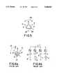
- FIGS. 1a-1dare frontal views of examples of a vibrator according to the present invention.
- FIG. 2a-2bis a circuit diagram according to the present invention.
- FIG. 3is another circuit diagram according to the present invention.
- FIG. 4is a further circuit diagram according to the present invention, applicable to the vibrator shown in FIG. 1d.
- FIG. 5is a frontal view of another example of the inventive vibrator.
- FIGS. 6a-6bshow an example of a prior art vibrator.
- FIGS. 1a-1dshow frontal views of examples of the vibrating elements of a vibratory gyroscope according to the present invention.
- reference numerals identical with those in the prior artrefer to identical parts.
- FIG. 1aillustrates a vibrator 4 which is identical in many respects with the prior art example shown in FIG. 6a. It includes a vibrating element 1 which is rectangular in cross-section and two piezoelectric elements 2 and 3 adhered on two adjacent sides of the vibrating element.
- Such vibrator 4 shown in FIG. 1ais excited basically in the same manner as the prior art example.
- piezoelectric elements 2 and 3are independently connected to the drive means through the common terminal 11.
- the piezoelectric elements 2 and 3generate voltages which have the same phase as each other when the variable terminal 22 is regulated so that the products of the capacitance values of the respective piezoelectric elements 2 and 3 and the resistance value between each piezoelectric element and the variable terminal 22 are equal to each other. Furthermore, even though strain on the piezoelectric elements 2 and 3 occurs due to temperature changes during non-operation of the gyroscope and this results in generation of electric charges in the piezoelectric elements 2 and 3, these electric charges are discharged through the variable terminal 22 which is grounded. Consequently, in the vibratory gyroscope according to the present invention, a sufficiently stabilized voltage level is obtained even in the period immediately after initiation of operation.
- FIG. 3shows another embodiment of the invention in which the variable terminal 22 is grounded through a fixed resistor 23 in addition to the provisions mentioned above.
- phase variation in the voltage generatedis effectively reduced by interaction of the generated voltage. Therefore, detection accuracy of angular velocity is further improved.
- FIG. 1aa type of a vibratory gyroscope having the vibrator shown in FIG. 1a.
- the present inventionis applicable to other types of vibrators as well, e.g., the type shown in FIG. 1b in which a vibrating element has a triangular shape in cross-section and two piezoelectric elements 2 and 3 are adhered on two sides thereof respectively, or the type shown in FIG. 1c in which a vibrating element has a rectangular shape in cross-section and separate piezoelectric elements 2 and 3 are adhered on a single side thereof.
- the vibrator shown in FIG. 1dis an example of a modification of the vibrator shown in FIG. 1a.
- the vibration element 1has a rectangular shape in cross-section, and two pairs of piezoelectric elements 2a-2b and 3a-3b are adhered on opposite sides of the vibrating element 1 so that the vibrator may be operated with increased excitation.
- pairs of piezoelectric elements on opposite sides of the vibration elementare connected to each other, and their respective terminals 5 and 6 are grounded through a variable resistor 21 and a fixed resistor 23 as shown in FIG. 4.
- a variable resistor 21 and a fixed resistor 23as shown in FIG. 4.
- FIG. 5shows a known vibrator having a vibrating element 1 with triangular shape in cross-section and piezoelectric elements 2, 3 and 24 are adhered on the three sides thereof.
- A.C. current for exciting the vibrator 4is applied through a terminal 25, and the generated voltages in the piezoelectric elements 2 and 3 are fed back to the drive means.
- angular velocityis measured by detecting the difference between the voltages generated in the respective piezoelectric elements.
- the vibrators shown in FIGS. 3, 4 and 5can also be used in the system shown in FIG. 2b.
Landscapes
- Engineering & Computer Science (AREA)
- Signal Processing (AREA)
- Physics & Mathematics (AREA)
- General Physics & Mathematics (AREA)
- Radar, Positioning & Navigation (AREA)
- Remote Sensing (AREA)
- Gyroscopes (AREA)
Abstract
Description
Claims (7)
Applications Claiming Priority (2)
| Application Number | Priority Date | Filing Date | Title |
|---|---|---|---|
| JP3-262564 | 1991-09-17 | ||
| JP3262564AJPH0571967A (en) | 1991-09-17 | 1991-09-17 | Vibration gyroscope |
Publications (1)
| Publication Number | Publication Date |
|---|---|
| US5460043Atrue US5460043A (en) | 1995-10-24 |
Family
ID=17377560
Family Applications (1)
| Application Number | Title | Priority Date | Filing Date |
|---|---|---|---|
| US07/946,284Expired - LifetimeUS5460043A (en) | 1991-09-17 | 1992-09-16 | Vibratory gyroscope |
Country Status (4)
| Country | Link |
|---|---|
| US (1) | US5460043A (en) |
| EP (1) | EP0533163B1 (en) |
| JP (1) | JPH0571967A (en) |
| DE (1) | DE69208787T2 (en) |
Cited By (3)
| Publication number | Priority date | Publication date | Assignee | Title |
|---|---|---|---|---|
| US5922954A (en)* | 1995-11-22 | 1999-07-13 | Murata Manufacturing Co., Ltd. | Vibration gyroscope and method for adjusting vibration-gyroscope characteristics |
| US5969248A (en)* | 1997-02-06 | 1999-10-19 | Aisin Seiki Kabushiki Kaisha | Oscillation type angular velocity sensor |
| US20120089361A1 (en)* | 2010-10-07 | 2012-04-12 | Dave Douglas | Apparatus and Method for Remote Monitoring |
Families Citing this family (4)
| Publication number | Priority date | Publication date | Assignee | Title |
|---|---|---|---|---|
| DE69210679T2 (en)* | 1991-06-07 | 1996-09-26 | Akai Electric | Vibration control device |
| JPH05312579A (en)* | 1992-05-08 | 1993-11-22 | Murata Mfg Co Ltd | Gyrocompass |
| JPH07260493A (en)* | 1994-03-22 | 1995-10-13 | Akai Electric Co Ltd | Angular velocity detection circuit in vibration gyro |
| RU2104557C1 (en)* | 1996-07-26 | 1998-02-10 | Товарищество с ограниченной ответственностью Фирма "Кварк" | Vibration-type angular-velocity transducer |
Citations (7)
| Publication number | Priority date | Publication date | Assignee | Title |
|---|---|---|---|---|
| US3520195A (en)* | 1965-10-11 | 1970-07-14 | Gen Electric | Solid state angular velocity sensing device |
| JPS6219713A (en)* | 1985-07-17 | 1987-01-28 | Tokyo Keiki Co Ltd | Gyro device |
| US4791815A (en)* | 1986-04-11 | 1988-12-20 | Matsushita Electric Industrial Co., Ltd. | Cyclically driven gyro and adjusting system therefor |
| JPH0266214A (en)* | 1988-08-31 | 1990-03-06 | Saeki Kensetsu Kogyo Kk | Construction of covering softest ground with fill-up soil |
| JPH02266215A (en)* | 1989-04-06 | 1990-10-31 | Murata Mfg Co Ltd | Vibrator |
| JPH02293621A (en)* | 1989-05-08 | 1990-12-04 | Murata Mfg Co Ltd | Vibrator |
| JPH02293620A (en)* | 1989-05-08 | 1990-12-04 | Murata Mfg Co Ltd | Vibration gyro |
Family Cites Families (1)
| Publication number | Priority date | Publication date | Assignee | Title |
|---|---|---|---|---|
| JPH0518754A (en)* | 1991-07-08 | 1993-01-26 | Murata Mfg Co Ltd | Vibrating gyro |
- 1991
- 1991-09-17JPJP3262564Apatent/JPH0571967A/enactivePending
- 1992
- 1992-09-16USUS07/946,284patent/US5460043A/ennot_activeExpired - Lifetime
- 1992-09-17EPEP92115935Apatent/EP0533163B1/ennot_activeExpired - Lifetime
- 1992-09-17DEDE69208787Tpatent/DE69208787T2/ennot_activeExpired - Fee Related
Patent Citations (7)
| Publication number | Priority date | Publication date | Assignee | Title |
|---|---|---|---|---|
| US3520195A (en)* | 1965-10-11 | 1970-07-14 | Gen Electric | Solid state angular velocity sensing device |
| JPS6219713A (en)* | 1985-07-17 | 1987-01-28 | Tokyo Keiki Co Ltd | Gyro device |
| US4791815A (en)* | 1986-04-11 | 1988-12-20 | Matsushita Electric Industrial Co., Ltd. | Cyclically driven gyro and adjusting system therefor |
| JPH0266214A (en)* | 1988-08-31 | 1990-03-06 | Saeki Kensetsu Kogyo Kk | Construction of covering softest ground with fill-up soil |
| JPH02266215A (en)* | 1989-04-06 | 1990-10-31 | Murata Mfg Co Ltd | Vibrator |
| JPH02293621A (en)* | 1989-05-08 | 1990-12-04 | Murata Mfg Co Ltd | Vibrator |
| JPH02293620A (en)* | 1989-05-08 | 1990-12-04 | Murata Mfg Co Ltd | Vibration gyro |
Non-Patent Citations (2)
| Title |
|---|
| T. Konno et al, "Excitation and Signal Detection in Vibratory Gyroscopes" pp. 126-127 of Report No. XXXIII-180-1114 (Oct. 1984), Report of Research Association for Application of Barium Titanate. |
| T. Konno et al, Excitation and Signal Detection in Vibratory Gyroscopes pp. 126 127 of Report No. XXXIII 180 1114 (Oct. 1984), Report of Research Association for Application of Barium Titanate.* |
Cited By (4)
| Publication number | Priority date | Publication date | Assignee | Title |
|---|---|---|---|---|
| US5922954A (en)* | 1995-11-22 | 1999-07-13 | Murata Manufacturing Co., Ltd. | Vibration gyroscope and method for adjusting vibration-gyroscope characteristics |
| US5969248A (en)* | 1997-02-06 | 1999-10-19 | Aisin Seiki Kabushiki Kaisha | Oscillation type angular velocity sensor |
| US20120089361A1 (en)* | 2010-10-07 | 2012-04-12 | Dave Douglas | Apparatus and Method for Remote Monitoring |
| US8858075B2 (en)* | 2010-10-07 | 2014-10-14 | Indorama Ventures (Oxide & Glycois) LLC | Apparatus and method for remote monitoring |
Also Published As
| Publication number | Publication date |
|---|---|
| DE69208787T2 (en) | 1996-07-25 |
| EP0533163A2 (en) | 1993-03-24 |
| EP0533163A3 (en) | 1993-05-19 |
| JPH0571967A (en) | 1993-03-23 |
| DE69208787D1 (en) | 1996-04-11 |
| EP0533163B1 (en) | 1996-03-06 |
Similar Documents
| Publication | Publication Date | Title |
|---|---|---|
| JP3894587B2 (en) | Micromachined speed sensor system for sensing rotational speed and method for minimizing parasitic drive voltage | |
| US5329816A (en) | Electrode pattern intended for tuning fork-controlled gyro | |
| EP1007977A1 (en) | Guard bands for tuning fork gyroscopes | |
| WO1998022827A9 (en) | Guard bands for tuning fork gyroscopes | |
| US5460043A (en) | Vibratory gyroscope | |
| JPH10300478A (en) | Angular velocity detecting element and angular velocity measuring device | |
| US6739191B2 (en) | Angular velocity sensor | |
| EP0658743B1 (en) | Vibrating gyroscope | |
| US6158281A (en) | Vibration gyroscope | |
| JP3732582B2 (en) | Angular velocity detector | |
| US6316942B1 (en) | Electrical potential sensor | |
| JPH10206166A (en) | Vibration-type gyroscope | |
| JPH09105637A (en) | Vibrating gyro | |
| JPH10227643A (en) | Vibrating gyro | |
| JP3419999B2 (en) | Angular velocity sensor | |
| JPH0642972A (en) | Piezoelectric oscillation gyro and adjusting method of resonance frequency of piezoelectric oscillation gyro | |
| JP3732602B2 (en) | Energy-confined piezoelectric vibration gyroscope | |
| JPH07260493A (en) | Angular velocity detection circuit in vibration gyro | |
| JP2526452Y2 (en) | Vibrating gyro | |
| JP2583701B2 (en) | Vibrating gyroscope and adjustment method thereof | |
| JP3732601B2 (en) | Energy-confined piezoelectric vibration gyroscope | |
| JPH0821735A (en) | Drive detector circuit of piezoelectric vibrator | |
| JP2000180490A (en) | Potential sensor | |
| JP3122925B2 (en) | Piezoelectric vibrator for piezoelectric vibrating gyroscope | |
| JPH0560562A (en) | Vibrating gyroscope |
Legal Events
| Date | Code | Title | Description |
|---|---|---|---|
| AS | Assignment | Owner name:AKAI ELECTRIC CO., LTD., JAPAN Free format text:ASSIGNMENT OF ASSIGNORS INTEREST.;ASSIGNOR:TERAJIMA, KOKICHI;REEL/FRAME:006277/0881 Effective date:19920922 | |
| STCF | Information on status: patent grant | Free format text:PATENTED CASE | |
| AS | Assignment | Owner name:MITSUBISHI ELECTRIC CORPORATION, JAPAN Free format text:ASSIGNMENT OF ASSIGNORS INTEREST;ASSIGNOR:AKAI ELECTRIC CO., LTD.;REEL/FRAME:008650/0196 Effective date:19970722 | |
| AS | Assignment | Owner name:MITSUBISHI ELECTRIC CORPORATION, JAPAN Free format text:CORRECTED ASSIGNMENT TO CORRECT PATENT NUMBERS PREVIOUSLY RECORDED AT REEL 8650, FRAME 0196.;ASSIGNOR:AKAI ELECTRIC CO., LTD.;REEL/FRAME:008753/0980 Effective date:19970722 | |
| FEPP | Fee payment procedure | Free format text:PAYOR NUMBER ASSIGNED (ORIGINAL EVENT CODE: ASPN); ENTITY STATUS OF PATENT OWNER: LARGE ENTITY | |
| FPAY | Fee payment | Year of fee payment:4 | |
| FPAY | Fee payment | Year of fee payment:8 | |
| FPAY | Fee payment | Year of fee payment:12 |