US5458997A - Rebalancing of lithium/silver vandium oxide (Li/SVO) cells for improved performance - Google Patents
Rebalancing of lithium/silver vandium oxide (Li/SVO) cells for improved performanceDownload PDFInfo
- Publication number
- US5458997A US5458997AUS08/293,354US29335494AUS5458997AUS 5458997 AUS5458997 AUS 5458997AUS 29335494 AUS29335494 AUS 29335494AUS 5458997 AUS5458997 AUS 5458997A
- Authority
- US
- United States
- Prior art keywords
- battery
- svo
- cathode
- electrolyte
- discharge
- Prior art date
- Legal status (The legal status is an assumption and is not a legal conclusion. Google has not performed a legal analysis and makes no representation as to the accuracy of the status listed.)
- Expired - Lifetime
Links
- WHXSMMKQMYFTQS-UHFFFAOYSA-NLithiumChemical compound[Li]WHXSMMKQMYFTQS-UHFFFAOYSA-N0.000titleabstractdescription16
- 229910052744lithiumInorganic materials0.000titleabstractdescription16
- 229910052709silverInorganic materials0.000title1
- 239000004332silverSubstances0.000title1
- 239000003792electrolyteSubstances0.000claimsabstractdescription16
- 239000003990capacitorSubstances0.000claimsdescription10
- 230000000747cardiac effectEffects0.000claimsdescription6
- 230000035939shockEffects0.000claimsdescription6
- 238000003487electrochemical reactionMethods0.000claims2
- 238000001514detection methodMethods0.000claims1
- RAVDHKVWJUPFPT-UHFFFAOYSA-Nsilver;oxido(dioxo)vanadiumChemical compound[Ag+].[O-][V](=O)=ORAVDHKVWJUPFPT-UHFFFAOYSA-N0.000abstractdescription4
- 239000012212insulatorSubstances0.000description32
- 239000010406cathode materialSubstances0.000description9
- 238000002955isolationMethods0.000description4
- 238000010276constructionMethods0.000description3
- 230000007774longtermEffects0.000description3
- 239000000463materialSubstances0.000description3
- -1polyethylenePolymers0.000description3
- 239000004810polytetrafluoroethyleneSubstances0.000description3
- 229920001343polytetrafluoroethylenePolymers0.000description3
- 208000001871TachycardiaDiseases0.000description2
- 230000003247decreasing effectEffects0.000description2
- 239000008151electrolyte solutionSubstances0.000description2
- 229920002313fluoropolymerPolymers0.000description2
- 239000004811fluoropolymerSubstances0.000description2
- 238000009413insulationMethods0.000description2
- 239000007788liquidSubstances0.000description2
- 229910003002lithium saltInorganic materials0.000description2
- 159000000002lithium saltsChemical class0.000description2
- 229910052751metalInorganic materials0.000description2
- 239000002184metalSubstances0.000description2
- 239000000203mixtureSubstances0.000description2
- 239000005486organic electrolyteSubstances0.000description2
- 239000003960organic solventSubstances0.000description2
- 239000002245particleSubstances0.000description2
- 229920002493poly(chlorotrifluoroethylene)Polymers0.000description2
- 239000005023polychlorotrifluoroethylene (PCTFE) polymerSubstances0.000description2
- 229920000642polymerPolymers0.000description2
- 229920000098polyolefinPolymers0.000description2
- 229910001220stainless steelInorganic materials0.000description2
- 239000010935stainless steelSubstances0.000description2
- 238000003466weldingMethods0.000description2
- OKTJSMMVPCPJKN-UHFFFAOYSA-NCarbonChemical compound[C]OKTJSMMVPCPJKN-UHFFFAOYSA-N0.000description1
- XTHFKEDIFFGKHM-UHFFFAOYSA-NDimethoxyethaneChemical compoundCOCCOCXTHFKEDIFFGKHM-UHFFFAOYSA-N0.000description1
- ZOKXTWBITQBERF-UHFFFAOYSA-NMolybdenumChemical compound[Mo]ZOKXTWBITQBERF-UHFFFAOYSA-N0.000description1
- 239000004698PolyethyleneSubstances0.000description1
- 239000004743PolypropyleneSubstances0.000description1
- 206010049447TachyarrhythmiaDiseases0.000description1
- 229910052770UraniumInorganic materials0.000description1
- OTGZYHVWXQELCL-UHFFFAOYSA-N[V].[Ag]Chemical compound[V].[Ag]OTGZYHVWXQELCL-UHFFFAOYSA-N0.000description1
- 239000011149active materialSubstances0.000description1
- 229910052783alkali metalInorganic materials0.000description1
- 239000010405anode materialSubstances0.000description1
- 238000005452bendingMethods0.000description1
- 239000011230binding agentSubstances0.000description1
- 239000006229carbon blackSubstances0.000description1
- 239000011248coating agentSubstances0.000description1
- 238000000576coating methodMethods0.000description1
- 239000000470constituentSubstances0.000description1
- 239000002001electrolyte materialSubstances0.000description1
- 229910002804graphiteInorganic materials0.000description1
- 239000010439graphiteSubstances0.000description1
- 238000003780insertionMethods0.000description1
- 230000037431insertionEffects0.000description1
- 230000001788irregularEffects0.000description1
- 229910001540lithium hexafluoroarsenate(V)Inorganic materials0.000description1
- MHCFAGZWMAWTNR-UHFFFAOYSA-Mlithium perchlorateChemical compound[Li+].[O-]Cl(=O)(=O)=OMHCFAGZWMAWTNR-UHFFFAOYSA-M0.000description1
- 229910001486lithium perchlorateInorganic materials0.000description1
- 238000000034methodMethods0.000description1
- 239000012229microporous materialSubstances0.000description1
- 229910052750molybdenumInorganic materials0.000description1
- 239000011733molybdenumSubstances0.000description1
- 229910052759nickelInorganic materials0.000description1
- 229910052758niobiumInorganic materials0.000description1
- 239000010955niobiumSubstances0.000description1
- GUCVJGMIXFAOAE-UHFFFAOYSA-Nniobium atomChemical compound[Nb]GUCVJGMIXFAOAE-UHFFFAOYSA-N0.000description1
- 229920000573polyethylenePolymers0.000description1
- 229920001155polypropylenePolymers0.000description1
- RUOJZAUFBMNUDX-UHFFFAOYSA-Npropylene carbonateChemical compoundCC1COC(=O)O1RUOJZAUFBMNUDX-UHFFFAOYSA-N0.000description1
- 238000007789sealingMethods0.000description1
- 239000007787solidSubstances0.000description1
- 238000002560therapeutic procedureMethods0.000description1
- 238000004804windingMethods0.000description1
Images


Classifications
- H—ELECTRICITY
- H01—ELECTRIC ELEMENTS
- H01M—PROCESSES OR MEANS, e.g. BATTERIES, FOR THE DIRECT CONVERSION OF CHEMICAL ENERGY INTO ELECTRICAL ENERGY
- H01M10/00—Secondary cells; Manufacture thereof
- H01M10/05—Accumulators with non-aqueous electrolyte
- H—ELECTRICITY
- H01—ELECTRIC ELEMENTS
- H01M—PROCESSES OR MEANS, e.g. BATTERIES, FOR THE DIRECT CONVERSION OF CHEMICAL ENERGY INTO ELECTRICAL ENERGY
- H01M10/00—Secondary cells; Manufacture thereof
- H01M10/42—Methods or arrangements for servicing or maintenance of secondary cells or secondary half-cells
- H—ELECTRICITY
- H01—ELECTRIC ELEMENTS
- H01M—PROCESSES OR MEANS, e.g. BATTERIES, FOR THE DIRECT CONVERSION OF CHEMICAL ENERGY INTO ELECTRICAL ENERGY
- H01M2200/00—Safety devices for primary or secondary batteries
- H—ELECTRICITY
- H01—ELECTRIC ELEMENTS
- H01M—PROCESSES OR MEANS, e.g. BATTERIES, FOR THE DIRECT CONVERSION OF CHEMICAL ENERGY INTO ELECTRICAL ENERGY
- H01M50/00—Constructional details or processes of manufacture of the non-active parts of electrochemical cells other than fuel cells, e.g. hybrid cells
- H01M50/10—Primary casings; Jackets or wrappings
- H01M50/102—Primary casings; Jackets or wrappings characterised by their shape or physical structure
- H01M50/103—Primary casings; Jackets or wrappings characterised by their shape or physical structure prismatic or rectangular
- H—ELECTRICITY
- H01—ELECTRIC ELEMENTS
- H01M—PROCESSES OR MEANS, e.g. BATTERIES, FOR THE DIRECT CONVERSION OF CHEMICAL ENERGY INTO ELECTRICAL ENERGY
- H01M6/00—Primary cells; Manufacture thereof
- H01M6/04—Cells with aqueous electrolyte
- H01M6/06—Dry cells, i.e. cells wherein the electrolyte is rendered non-fluid
- H01M6/10—Dry cells, i.e. cells wherein the electrolyte is rendered non-fluid with wound or folded electrodes
- Y—GENERAL TAGGING OF NEW TECHNOLOGICAL DEVELOPMENTS; GENERAL TAGGING OF CROSS-SECTIONAL TECHNOLOGIES SPANNING OVER SEVERAL SECTIONS OF THE IPC; TECHNICAL SUBJECTS COVERED BY FORMER USPC CROSS-REFERENCE ART COLLECTIONS [XRACs] AND DIGESTS
- Y02—TECHNOLOGIES OR APPLICATIONS FOR MITIGATION OR ADAPTATION AGAINST CLIMATE CHANGE
- Y02E—REDUCTION OF GREENHOUSE GAS [GHG] EMISSIONS, RELATED TO ENERGY GENERATION, TRANSMISSION OR DISTRIBUTION
- Y02E60/00—Enabling technologies; Technologies with a potential or indirect contribution to GHG emissions mitigation
- Y02E60/10—Energy storage using batteries
- Y—GENERAL TAGGING OF NEW TECHNOLOGICAL DEVELOPMENTS; GENERAL TAGGING OF CROSS-SECTIONAL TECHNOLOGIES SPANNING OVER SEVERAL SECTIONS OF THE IPC; TECHNICAL SUBJECTS COVERED BY FORMER USPC CROSS-REFERENCE ART COLLECTIONS [XRACs] AND DIGESTS
- Y02—TECHNOLOGIES OR APPLICATIONS FOR MITIGATION OR ADAPTATION AGAINST CLIMATE CHANGE
- Y02P—CLIMATE CHANGE MITIGATION TECHNOLOGIES IN THE PRODUCTION OR PROCESSING OF GOODS
- Y02P70/00—Climate change mitigation technologies in the production process for final industrial or consumer products
- Y02P70/50—Manufacturing or production processes characterised by the final manufactured product
Definitions
- This inventionis broadly concerned with improving the performance of implantable cardiac defibrillators. These are products used for treatment of tachyarrhythmias, the irregular, rapid heartbeats that can be fatal if uncorrected. These devices produce a shock to the heart when called upon to correct an onset of tachyarrhythmia. The shock is delivered by a capacitor, which has been charged by the battery.
- the electrical power source of choice at present for operating these electronic deviceshas been the Li/SVO battery or cell where SVO stands for silver vanadium oxide of the type disclosed in U.S. Pat. No. 4,310,609 or 4,391,729 issued to Liang et al or U.S. Pat. No. 5,221,453 issued to Crespi which are incorporated herein by reference in their entirety and used in batteries or cells as disclosed in U.S. Pat. Nos. 5,312,458; 5,298,349; 5,250,373; 5,147,737; 5,114,811; 5,114,810; 4,964,877; and 4,830,840.
- This particular cell chemistryhas been useful for the defibrillator application because of its ability to produce pulses of energy which can charge the capacitors of the defibrillator in a timely manner.
- the shockmust be provided to the patient in a matter of a few seconds.
- the Li/SVO batteryis typically called upon to charge the capacitors to deliver a shock of up to 40 joules within 10 seconds or less and to do so several times in succession if additional shocks are required.
- This inventionthen is more specifically directed to improvements in Li/SVO cells to avoid this resistance buildup and render their operation more predictable as a basis for simple EOS determination.
- the resistance of conventionally balanced cathode limited Li/SVO cellsincreases as a function of time after the cell is discharged to the second voltage plateau on its discharge curve.
- the present inventionrebalances the cell constituents so that discharge occurs in the cell only through the first voltage plateau and first ramp to the start of the second voltage plateau and thus avoids the portion of the curve in which resistance buildup occurs. This rebalancing can be accomplished by reconfiguring the battery components to include less of the lithium and electrolyte material in the cell than would be used in a conventionally balanced cell.
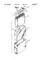
- FIG. 1is an exploded perspective view showing the insertion of an electrode assembly into a battery case together with insulator materials.
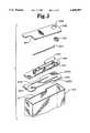
- FIG. 2is a partial cut-away perspective view of a completed battery showing the connections of the tabs of the electrode with the case elements.
- FIG. 3is a partial cut-away perspective view of the isolation components for a battery.
- FIG. 4is an exploded perspective view showing the application of the insulator and case top to the case and electrode assembly of FIG. 1.
- FIG. 5is a graph showing the discharge of a Li/SVO battery and as modified by the present invention.
- FIG. 6is a graph showing a discharge curve for a conventionally balanced cathode limited Li/SVO battery.
- FIG. 7is a graph showing a discharge curve for a rebalanced anode limited Li/SVO battery according to this invention.
- Batteries or cellsare volumetrically constrained systems.
- the amounts of components that go into a batterycan not exceed the available volume of the battery case.
- the appropriate amount of some componentsdepends on the amount of other components that are used. These components must be “balanced” to provide discharge to the extent desired.
- cathode limited Li/SVO batteryall conventionally balanced Li/SVO batteries known to date are of this type
- the capacity (Q + ) of the cathodemust not exceed the capacity (Q - ) of the anode.
- Cathode limited cellsare also conventionally used in virtually all battery powered implantable medical devices such as heart pacemakers because of the proven reliability of their discharge over the long periods during which they are implanted.
- the volume occupied by the other battery componentsalso depends on the cathode capacity (Q + ) as reflected by the amount of cathode material in the battery.
- the amount of electrolytedepends on the amount of cathode material and the amount of it to be discharged since the cathode material swells as the battery is discharged and requires more electrolyte to fill the additional cathode volume.
- the volume of the separator and current collectordepends on the area of the electrodes. The area of the electrodes depends on the area required for consistent pulse output as the battery is discharged. All of these components must be adjusted for a given battery volume.
- Li/SVO batteriesAlthough a variety of battery configurations and constructions are possible for Li/SVO batteries, a coiled or wrapped configuration will be discussed herein as an exemplar of a conventional Li/SVO battery for use with the invention. The invention is of course applicable to any configuration and construction.
- a coiled electrode assemblycomprised of elongated anode and cathode subassemblies including anode material (Li) or cathode material (silver vanadium oxide--SVO which may also include PTFE binder, carbon black and graphite) pressed onto a metal current collector (Ni, Ti, etc.) and enveloped with a separator of microporous material such as polyethylene, polypropylene or the like are overlaid with respect to each other and coiled up.
- Connector tabsmay be included within the electrode assembly for making electrical connection thereto.
- FIGS. 1-4Assembly of the electrode assembly 120 into a battery is shown in FIGS. 1-4.
- a coil insulator 200is placed onto the electrode assembly 120.
- the coil insulatorincludes a notch 202 to accommodate anode connector tab 22 and slits 204, 206 208 to accommodate anode connector tab 20, and cathode connector tabs 70, 72 respectively.
- the electrode assembly 120is also inserted into an insulative case liner 210.
- the case liner 210preferably extends at its top edge above the edge of the electrode assembly 120 in order to provide an overlap with other insulative elements. If so, it may include a notch 211 on one side in order to allow the easy connection of the anode connector tabs 20, 22 to the case 220.
- the coil insulator 200 and case liner 210are preferably made from a polyolefin polymer or a fluoropolymer such as PTFE or PCTFE.
- the electrode assembly 120 and case liner 210are then inserted into a prismatic case 220, preferably made of stainless steel.
- a case cover 230 and a pin insulator 240are shown along with the electrode assembly 120 and prismatic case 220.
- the case cover 230has a glassed in feedthrough 232 and feedthrough pin 233 extending through an aperture in the case cover 230 that has a bend 234 which is intended to place the feedthrough 232 in alignment with the cathode connector tabs 70, 72.
- the case cover 230also has a fill port 236.
- the case cover 230is made from stainless steel and the feedthrough pin 233 is preferably niobium or molybdenum.
- the pin insulator 240has an aperture 242 leading into a raised portion 244 which receives the feedthrough pin 233 and insulates the feedthrough pin 233 from contact with the case cover 230.
- the raised portionforms a chamber which isolates the cathode connections.
- Additional insulation in the form of tubing or a coatingmay also be included on the feedthrough pin 233 and feedthrough 232 at locations which will not be welded to further insulate the feedthrough pin 233 and feedthrough 232 and also an additional cover insulator (not shown) could be applied to the underside of the case cover 230 to provide additional insulation for the case cover 230.
- the feedthrough pin 233is welded to the cathode connector tabs 70, 72 as shown in FIG. 2 and the anode connector tabs 20, 22 are bent into an "L" shape as shown in FIG. 2 and are welded to the side of the case 220 thereby making the metal case 220 one terminal or contact for the battery (i.e. a case negative design).
- the feedthrough pin 233is then inserted through a split (not shown) in the pin insulator 240 until it projects through the aperture 242 of the pin insulator 240.
- the electrode assembly 120may be out of the case 220 during some of the welding and bending operations.
- the case cover 230is then welded to the case 220 to seal the electrode assembly 120 in the case.
- a cover insulator 245is adapted to fit under the case cover 230 with an aperture 246 to accommodate the feedthrough 232 and feedthrough pin 233 and a cut-away portion 247 to accommodate the fill port 236.
- the cover insulator 245is applied to the underside of the case cover 230.
- a feedthrough insulator 250then slides over the feedthrough pin 233 and over the feedthrough 232 into contact with the cover insulator 245. Once the feedthrough insulator 250 is in place, a tubular insulator 255 is slipped over the feedthrough pin 233 until it contacts the feedthrough insulator 250.
- the feedthrough pin 233is then bent into its desired configuration for connection with cathode connector tabs 70, 72 as shown in FIG. 4.
- the pin insulator 240is shown with a split 241 which extends from the edge of the pin insulator 240 to the aperture 242. Again, the pin insulator 240 has an aperture 242 leading into a raised portion 244 or recess which receives the feedthrough pin 233 and the tubular insulator 255 over the feedthrough pin and insulates the feedthrough pin 233 from contact with the case cover 230 at the point where the feedthrough pin is welded to the cathode connector tabs 70, 72.
- the split 241allows the pin insulator 240 to be placed on the feedthrough pin 233 after the feedthrough pin has been welded to the cathode tabs 70, 72.
- the tubular insulator 255therefore extends through the aperture 242, thereby preventing any discontinuity in the isolation of the cathode connector tabs 70, 72 and feedthrough pin 233 from elements at anode potential.
- a coil insulator 202ais shown with a notch 202 to accommodate anode connector tab 22 and slits 204, 206 to accommodate anode connector tab 20, and cathode connector tab 70 respectively.
- a notch 208ais also provided to accommodate cathode connector tab 72 in place of the slit 208 shown in FIG. 1.
- the electrode assembly 120is also inserted into an insulative case liner 210.
- All of the case isolation componentsincluding the cover insulator 245, the feedthrough insulator 250, the tubular insulator 255, the pin insulator 240, the coil insulator 202a and the case liner 210 are molded or extruded self-supporting polymeric parts preferably made from a polyolefin polymer or a fluoropolymer such as PTFE or PCTFE.
- the electrolyte solutioncan be an alkali metal salt in an organic solvent such as a lithium salt (i.e., 1.0M LiClO 4 or LiAsF 6 ) in a 50/50 mixture of propylene carbonate and dimethoxyethane.
- the sealing processmay include, for example, making a first seal by pressing a plug into the aperture of the fill port 236 and making a second seal by welding a cap or disc over the fill port 236. Material utilized for leak checking hermetic seals may be included between the first and second seals.
- the batteryincluding a solid cathode, liquid organic electrolyte and a lithium anode for delivering high current pulses.
- the batteryfurther includes a casing containing the battery components and the cathode structure therein is wound in a plurality of turns, with the lithium anode interposed between the turns of the cathode winding.
- the casingalso contains a non-aqueous liquid organic electrolyte comprising a combination of lithium salt and an organic solvent operatively contacting the anode and the cathode.
- An electrical connectionis provided to the anode and an electrical connection is provided to the cathode.
- the cathodeincludes as active material silver vanadium oxide. Such cells find advantageous use as power sources for implantable cardiac defibrillators. This is an example of the type of battery with which this invention is particularly concerned.
- This inventionconsists of rebalancing the cell such that it contains sufficient lithium and electrolyte to be discharged only to the point labeled above as "First Plateau Balanced".
- the volume made available by using less lithium and electrolyteallows more room for cathode material, extending the first plateau as shown by the dotted line 325.
- the open circuit voltage discharge curve 350shows the characteristic first and second voltage plateaus 355,360. Pulse voltage is shown in curve 370 for a first discharge rate and in curve 375 for a slow discharge rate. Note that the curve for the second discharge rate diverges from the curve for the first discharge rate at the start of the second voltage plateau. The divergence in the curves 370, 375 indicates a rapid increase in resistance in the region of the second voltage plateau 360. This resistance increase is characteristic of some conventionally balanced lithium/silver vanadium oxide batteries and, when it occurs, it always becomes significant near the start of the second voltage plateau.
- the defibrillatorcharges capacitors to a predetermined energy level when a defibrillation therapy is required.
- the amount of time required for chargingis called the “charge time,” which depends on the load voltage.
- the deviceno longer functions adequately when the pulse voltage reaches some minimum value.
- the pulse voltagestays substantially constant throughout discharge, so it can start at a lower value.
- the electrode areacan be decreased. Decreasing the electrode area reduces the amount of volume occupied by separator and current collectors, so more volume is available for additional cathode material (see Tables and FIG. 7).
- the values of Q + , Q - , V electrolyte , and A electrode , and the volumes of other components obtainedare shown in the Table 1.
- the discharge curve of FIG. 7shows the background voltage curve 380 and the pulse discharge curve 385.
- the expected discharge curve 385 for such a batteryis the same regardless of discharge rate, because discharge is avoided in the region where the resistance increase occurs.
Landscapes
- Engineering & Computer Science (AREA)
- Manufacturing & Machinery (AREA)
- Chemical & Material Sciences (AREA)
- Chemical Kinetics & Catalysis (AREA)
- Electrochemistry (AREA)
- General Chemical & Material Sciences (AREA)
- Primary Cells (AREA)
- Electrotherapy Devices (AREA)
- Secondary Cells (AREA)
Abstract
Description
This invention is broadly concerned with improving the performance of implantable cardiac defibrillators. These are products used for treatment of tachyarrhythmias, the irregular, rapid heartbeats that can be fatal if uncorrected. These devices produce a shock to the heart when called upon to correct an onset of tachyarrhythmia. The shock is delivered by a capacitor, which has been charged by the battery.
The electrical power source of choice at present for operating these electronic devices has been the Li/SVO battery or cell where SVO stands for silver vanadium oxide of the type disclosed in U.S. Pat. No. 4,310,609 or 4,391,729 issued to Liang et al or U.S. Pat. No. 5,221,453 issued to Crespi which are incorporated herein by reference in their entirety and used in batteries or cells as disclosed in U.S. Pat. Nos. 5,312,458; 5,298,349; 5,250,373; 5,147,737; 5,114,811; 5,114,810; 4,964,877; and 4,830,840. This particular cell chemistry has been useful for the defibrillator application because of its ability to produce pulses of energy which can charge the capacitors of the defibrillator in a timely manner. For example, once the implantable defibrillator has identified a tachyarrythmia the shock must be provided to the patient in a matter of a few seconds. Thus, the Li/SVO battery is typically called upon to charge the capacitors to deliver a shock of up to 40 joules within 10 seconds or less and to do so several times in succession if additional shocks are required. Unfortunately, on long-term discharge, these cells can develop high resistance that impairs their ability to charge the capacitors in a timely manner and therefore renders much of the capacity of the cell unavailable for long term use in an implantable defibrillator. Further, the end of service (EOS) determination in these cells is complicated by the variable nature of the resistance buildup.
This invention then is more specifically directed to improvements in Li/SVO cells to avoid this resistance buildup and render their operation more predictable as a basis for simple EOS determination.
The resistance of conventionally balanced cathode limited Li/SVO cells increases as a function of time after the cell is discharged to the second voltage plateau on its discharge curve. The present invention rebalances the cell constituents so that discharge occurs in the cell only through the first voltage plateau and first ramp to the start of the second voltage plateau and thus avoids the portion of the curve in which resistance buildup occurs. This rebalancing can be accomplished by reconfiguring the battery components to include less of the lithium and electrolyte material in the cell than would be used in a conventionally balanced cell. Contrary to what might be expected from the use of a lesser amount of reactive lithium in the cell than is needed to fully discharge the cathode, superior long term performance is obtained by this rebalancing since the same useful capacity can be provided in a defibrillator application as in a conventionally balanced cell but at a higher voltage toward the end of the discharge cycle so that the average capacitor charge time is lowered toward the end of the cell's useful life. Moreover, a more nearly constant resistance is obtained during discharge so that the EOS indication is made simpler and more predictable.
FIG. 1 is an exploded perspective view showing the insertion of an electrode assembly into a battery case together with insulator materials.
FIG. 2 is a partial cut-away perspective view of a completed battery showing the connections of the tabs of the electrode with the case elements.
FIG. 3 is a partial cut-away perspective view of the isolation components for a battery.
FIG. 4 is an exploded perspective view showing the application of the insulator and case top to the case and electrode assembly of FIG. 1.
FIG. 5 is a graph showing the discharge of a Li/SVO battery and as modified by the present invention.
FIG. 6 is a graph showing a discharge curve for a conventionally balanced cathode limited Li/SVO battery.
FIG. 7 is a graph showing a discharge curve for a rebalanced anode limited Li/SVO battery according to this invention.
Batteries or cells are volumetrically constrained systems. The amounts of components that go into a battery (cathode, anode, separator, current collectors, electrolyte, etc.) can not exceed the available volume of the battery case. In addition, the appropriate amount of some components depends on the amount of other components that are used. These components must be "balanced" to provide discharge to the extent desired.
For example, in a cathode limited Li/SVO battery (all conventionally balanced Li/SVO batteries known to date are of this type) such as is used in a defibrillator application, the capacity (Q+) of the cathode must not exceed the capacity (Q-) of the anode. Cathode limited cells are also conventionally used in virtually all battery powered implantable medical devices such as heart pacemakers because of the proven reliability of their discharge over the long periods during which they are implanted. The volume occupied by the other battery components also depends on the cathode capacity (Q+) as reflected by the amount of cathode material in the battery. The amount of electrolyte depends on the amount of cathode material and the amount of it to be discharged since the cathode material swells as the battery is discharged and requires more electrolyte to fill the additional cathode volume. The volume of the separator and current collector depends on the area of the electrodes. The area of the electrodes depends on the area required for consistent pulse output as the battery is discharged. All of these components must be adjusted for a given battery volume.
Although a variety of battery configurations and constructions are possible for Li/SVO batteries, a coiled or wrapped configuration will be discussed herein as an exemplar of a conventional Li/SVO battery for use with the invention. The invention is of course applicable to any configuration and construction.
With reference to FIG. 1 such an exemplar battery construction is described. It can be seen that a coiled electrode assembly comprised of elongated anode and cathode subassemblies including anode material (Li) or cathode material (silver vanadium oxide--SVO which may also include PTFE binder, carbon black and graphite) pressed onto a metal current collector (Ni, Ti, etc.) and enveloped with a separator of microporous material such as polyethylene, polypropylene or the like are overlaid with respect to each other and coiled up. Connector tabs may be included within the electrode assembly for making electrical connection thereto.
Assembly of theelectrode assembly 120 into a battery is shown in FIGS. 1-4. In FIG. 1, acoil insulator 200 is placed onto theelectrode assembly 120. The coil insulator includes anotch 202 to accommodateanode connector tab 22 andslits anode connector tab 20, andcathode connector tabs electrode assembly 120 is also inserted into aninsulative case liner 210. Thecase liner 210 preferably extends at its top edge above the edge of theelectrode assembly 120 in order to provide an overlap with other insulative elements. If so, it may include anotch 211 on one side in order to allow the easy connection of theanode connector tabs case 220. Thecoil insulator 200 andcase liner 210 are preferably made from a polyolefin polymer or a fluoropolymer such as PTFE or PCTFE. Theelectrode assembly 120 andcase liner 210 are then inserted into aprismatic case 220, preferably made of stainless steel. In FIG. 4 acase cover 230 and apin insulator 240 are shown along with theelectrode assembly 120 andprismatic case 220. Thecase cover 230 has a glassed infeedthrough 232 andfeedthrough pin 233 extending through an aperture in thecase cover 230 that has abend 234 which is intended to place thefeedthrough 232 in alignment with thecathode connector tabs case cover 230 also has afill port 236. Thecase cover 230 is made from stainless steel and thefeedthrough pin 233 is preferably niobium or molybdenum. Thepin insulator 240 has anaperture 242 leading into a raisedportion 244 which receives thefeedthrough pin 233 and insulates thefeedthrough pin 233 from contact with thecase cover 230. In combination with one side of thecoil insulator 200, which is immediately below thepin insulator 240, the raised portion forms a chamber which isolates the cathode connections. Additional insulation in the form of tubing or a coating (not shown) may also be included on thefeedthrough pin 233 andfeedthrough 232 at locations which will not be welded to further insulate thefeedthrough pin 233 andfeedthrough 232 and also an additional cover insulator (not shown) could be applied to the underside of thecase cover 230 to provide additional insulation for thecase cover 230. Thefeedthrough pin 233 is welded to thecathode connector tabs anode connector tabs case 220 thereby making themetal case 220 one terminal or contact for the battery (i.e. a case negative design). Thefeedthrough pin 233 is then inserted through a split (not shown) in thepin insulator 240 until it projects through theaperture 242 of thepin insulator 240. Theelectrode assembly 120 may be out of thecase 220 during some of the welding and bending operations. Thecase cover 230 is then welded to thecase 220 to seal theelectrode assembly 120 in the case.
Referring now also to FIG. 3, the isolation components for the battery are shown in greater detail. Acover insulator 245 is adapted to fit under thecase cover 230 with anaperture 246 to accommodate thefeedthrough 232 andfeedthrough pin 233 and a cut-awayportion 247 to accommodate thefill port 236. Thecover insulator 245 is applied to the underside of thecase cover 230. Afeedthrough insulator 250 then slides over thefeedthrough pin 233 and over thefeedthrough 232 into contact with thecover insulator 245. Once thefeedthrough insulator 250 is in place, atubular insulator 255 is slipped over thefeedthrough pin 233 until it contacts thefeedthrough insulator 250. Thefeedthrough pin 233 is then bent into its desired configuration for connection withcathode connector tabs pin insulator 240 is shown with asplit 241 which extends from the edge of thepin insulator 240 to theaperture 242. Again, thepin insulator 240 has anaperture 242 leading into a raisedportion 244 or recess which receives thefeedthrough pin 233 and thetubular insulator 255 over the feedthrough pin and insulates thefeedthrough pin 233 from contact with thecase cover 230 at the point where the feedthrough pin is welded to thecathode connector tabs split 241 allows thepin insulator 240 to be placed on thefeedthrough pin 233 after the feedthrough pin has been welded to thecathode tabs tubular insulator 255 therefore extends through theaperture 242, thereby preventing any discontinuity in the isolation of thecathode connector tabs feedthrough pin 233 from elements at anode potential. A coil insulator 202a is shown with anotch 202 to accommodateanode connector tab 22 and slits 204, 206 to accommodateanode connector tab 20, andcathode connector tab 70 respectively. Anotch 208a is also provided to accommodatecathode connector tab 72 in place of theslit 208 shown in FIG. 1. Theelectrode assembly 120 is also inserted into aninsulative case liner 210. All of the case isolation components including thecover insulator 245, thefeedthrough insulator 250, thetubular insulator 255, thepin insulator 240, the coil insulator 202a and thecase liner 210 are molded or extruded self-supporting polymeric parts preferably made from a polyolefin polymer or a fluoropolymer such as PTFE or PCTFE. The result of this insulator configuration is that the cathode connections are thoroughly isolated from the portions of the battery at anode potential and that the feedthrough connection is thoroughly isolated from stray particles of material from the cathode and from lithium particles that may form during discharge of the battery.
An appropriate electrolyte solution is introduced through thefill port 236 and thefill port 236 is then sealed. The electrolyte solution can be an alkali metal salt in an organic solvent such as a lithium salt (i.e., 1.0M LiClO4 or LiAsF6) in a 50/50 mixture of propylene carbonate and dimethoxyethane. The sealing process (not shown) may include, for example, making a first seal by pressing a plug into the aperture of thefill port 236 and making a second seal by welding a cap or disc over thefill port 236. Material utilized for leak checking hermetic seals may be included between the first and second seals.
From the above it is seen that there is provided, as an example of a battery which may make use of this invention, the battery including a solid cathode, liquid organic electrolyte and a lithium anode for delivering high current pulses. The battery further includes a casing containing the battery components and the cathode structure therein is wound in a plurality of turns, with the lithium anode interposed between the turns of the cathode winding. The casing also contains a non-aqueous liquid organic electrolyte comprising a combination of lithium salt and an organic solvent operatively contacting the anode and the cathode. An electrical connection is provided to the anode and an electrical connection is provided to the cathode. The cathode includes as active material silver vanadium oxide. Such cells find advantageous use as power sources for implantable cardiac defibrillators. This is an example of the type of battery with which this invention is particularly concerned.
As already indicated, such batteries in cathode limited design are generally known in the art and used to power defibrillators. As shown in FIG. 5, the open-circuit voltage of such Li/SVO cells have two voltage plateaus, afirst voltage plateau 300 at about 3.2 v and asecond voltage plateau 310 at about 2.6 v, with two slopingregions line 325.
Referring now to FIG. 6, expected discharge curves for the conventional type battery are shown for various application rate discharge tests. The open circuitvoltage discharge curve 350 shows the characteristic first and second voltage plateaus 355,360. Pulse voltage is shown incurve 370 for a first discharge rate and incurve 375 for a slow discharge rate. Note that the curve for the second discharge rate diverges from the curve for the first discharge rate at the start of the second voltage plateau. The divergence in thecurves background voltage curve 380 and thepulse discharge curve 385. The expecteddischarge curve 385 for such a battery is the same regardless of discharge rate, because discharge is avoided in the region where the resistance increase occurs.
TABLE 1 ______________________________________ Volume Utilization of Conventional and Rebalanced Batteries Conventional Balance - Rebalanced - FIG. 6 FIG. 7 ______________________________________ Battery External Dimensions Height 2.54 cm 2.54 cm Width 2.54 cm 2.54 cm Thickness 0.90 cm 0.90 cm Cathode Capacity (Q.sub.+) 1085 mAh 1676 mAh Anode Capacity (Q.sub.-) 1592 mAh 1020 mAh Active Electrode Area 60.3 cm.sup.2 42.8 cm.sup.2 (A.sub.electrode) Separator Volume (V.sub.separator) 0.58 cm.sup.3 0.44 cm.sup.3 Current Collector Volume 0.27 cm.sup.3 0.19 cm.sup.3 (V.sub.current collectors) Electrolyte(V.sub.electrolyte) 2 cc 1.5 cc ______________________________________
Referring now to Table 2 below, conventional balance is compared to rebalanced according to the present invention.
TABLE 2 ______________________________________ CONVENTIONAL BALANCE REBALANCED ______________________________________ Q.sub.- (anode) Q-/Q.sub.+ > 1 0.45 < Q-/Q+ <0.7 Q.sub.+ (cathode) V.sub.electrolyte >1.2 cm.sup.3 /Ah <1 cm.sup.3 /Ah Q.sub.+ (cathode) ______________________________________ Note: Q.sub.+ is based on conventional use of 6.67 eq. Li/SVO to deplete cathode not deliverable capacity but calculated based on amount of cathode included initially in the battery.
The above Examples and disclosure are intended to be illustrative and not exhaustive. These examples and description will suggest many variations and alternatives to one of ordinary skill in this art. All these alternatives and variations are intended to be included within the scope of the attached claims. Those familiar with the art may recognize other equivalents to the specific embodiments described herein which equivalents are also intended to be encompassed by the claims attached hereto.
Claims (7)
1. A Li/SVO battery comprised of an anode, a cathode, and an electrolyte in relative amounts wherein the battery is anode limited such that the battery discharge is substantially completed as the open circuit battery voltage drops to about 2.6 volts.
2. A Li/SVO battery having a ##EQU1## of about 0.45-0.70; and a ##EQU2## of about <1 cm3 /Ah
3. The Li/SVO battery of claim 1 wherein the quantity of the electrolyte is provided only in the amount needed for the electrochemical reaction involving the cathode.
4. In an implantable cardiac defibrillator, said defibrillator including a capacitor capable of providing an intense shock for terminating a tachyrhythmia in a patient and a battery which charges the capacitor upon detection of the tachyrhythmia by providing a pulse of energy to the capacitor, the improvement which comprises: an anode limited Li/SVO battery charging the capacitor.
5. A cardiac defibrillator according to claim 4 wherein the Li/SVO battery is comprised of components in predetermined relative limited amounts whereby discharge is substantially completed as the open circuit battery voltage drops to about 2.6 volts.
6. A cardiac defibrillator according to claim 4 wherein the Li/SVO battery has a ##EQU3## of about 0.45-0.70; and a ##EQU4## of about <1 cm3 /Ah.
7. A cardiac defibrillator according to claim 4 wherein the Li/SVO battery is limited in electrolyte so as to provide only the electrolyte amount needed for the electrochemical reaction involving the cathode.
Priority Applications (4)
| Application Number | Priority Date | Filing Date | Title |
|---|---|---|---|
| US08/293,354US5458997A (en) | 1994-08-19 | 1994-08-19 | Rebalancing of lithium/silver vandium oxide (Li/SVO) cells for improved performance |
| EP95305378AEP0707351B1 (en) | 1994-08-19 | 1995-08-01 | Rebalancing of lithium/silver vanadium oxide (LI/SVO) cells |
| DE69501450TDE69501450T2 (en) | 1994-08-19 | 1995-08-01 | Compensation of lithium / (silver vanadium) oxide cells (LI / SVO) |
| JP23321095AJP3326671B2 (en) | 1994-08-19 | 1995-08-21 | Cardiac defibrillator using rebalanced lithium / silver vanadium oxide battery |
Applications Claiming Priority (1)
| Application Number | Priority Date | Filing Date | Title |
|---|---|---|---|
| US08/293,354US5458997A (en) | 1994-08-19 | 1994-08-19 | Rebalancing of lithium/silver vandium oxide (Li/SVO) cells for improved performance |
Publications (1)
| Publication Number | Publication Date |
|---|---|
| US5458997Atrue US5458997A (en) | 1995-10-17 |
Family
ID=23128740
Family Applications (1)
| Application Number | Title | Priority Date | Filing Date |
|---|---|---|---|
| US08/293,354Expired - LifetimeUS5458997A (en) | 1994-08-19 | 1994-08-19 | Rebalancing of lithium/silver vandium oxide (Li/SVO) cells for improved performance |
Country Status (4)
| Country | Link |
|---|---|
| US (1) | US5458997A (en) |
| EP (1) | EP0707351B1 (en) |
| JP (1) | JP3326671B2 (en) |
| DE (1) | DE69501450T2 (en) |
Cited By (85)
| Publication number | Priority date | Publication date | Assignee | Title |
|---|---|---|---|---|
| US5690685A (en)* | 1995-10-27 | 1997-11-25 | Angeion Corporation | Automatic battery-maintaining implantable cardioverter defibrillator and method for use |
| US5716728A (en)* | 1996-11-04 | 1998-02-10 | Wilson Greatbatch Ltd. | Alkali metal electrochemical cell with improved energy density |
| FR2766720A1 (en)* | 1997-07-30 | 1999-02-05 | Medtronic Inc | BATTERY FOR IMPLANTABLE MEDICAL DEVICES |
| US5895733A (en)* | 1997-02-03 | 1999-04-20 | Medtronic, Inc. | Synthesis method for silver vanadium oxide |
| US5899923A (en)* | 1996-03-22 | 1999-05-04 | Angeion Corporation | Automatic capacitor maintenance system for an implantable cardioverter defibrillator |
| US5955218A (en)* | 1996-12-18 | 1999-09-21 | Medtronic, Inc. | Heat-treated silver vanadium oxide for use in batteries for implantable medical devices |
| US6008625A (en)* | 1998-01-16 | 1999-12-28 | Wilson Greatbatch Ltd. | Use of double cells to power an implantable medical device |
| US6010803A (en)* | 1996-12-05 | 2000-01-04 | Medtronic, Inc. | Metal injection molded cover for an electrochemical cell |
| US6037077A (en)* | 1998-07-08 | 2000-03-14 | Wilson Greatbatch Ltd. | Electrode assembly for high energy devices |
| US6165638A (en)* | 1997-04-04 | 2000-12-26 | Wilson Greatbatch Ltd. | Electrochemical cell having multiplate and jellyroll electrodes with differing discharge rate regions |
| US6171729B1 (en)* | 1998-01-02 | 2001-01-09 | Wilson Greatbatch Ltd | Control of swelling in alkali metal electrochemical cells |
| US6225007B1 (en) | 1999-02-05 | 2001-05-01 | Nanogram Corporation | Medal vanadium oxide particles |
| US6258473B1 (en) | 1997-04-04 | 2001-07-10 | Wilson Greatbatch Ltd. | Electrochemical cell having multiplate electrodes with differing discharge rate regions |
| US6391494B2 (en) | 1999-05-13 | 2002-05-21 | Nanogram Corporation | Metal vanadium oxide particles |
| US6445948B1 (en) | 1998-04-03 | 2002-09-03 | Medtronic, Inc. | Implantable medical device having a substantially flat battery |
| EP0829913A3 (en)* | 1996-09-13 | 2002-12-04 | Matsushita Electric Industrial Co., Ltd. | Solid state rechargeable lithium battery, stacking battery, and charging method of the same |
| US20020183800A1 (en)* | 2001-05-30 | 2002-12-05 | Medtronic, Inc. | Implantable medical device with a dual power source |
| US6503646B1 (en) | 2000-08-28 | 2003-01-07 | Nanogram Corporation | High rate batteries |
| US20030148176A1 (en)* | 2000-03-09 | 2003-08-07 | Gootzen Jozef Franciscus Elisabeth | Battery comprising a plurality of series-connected galvanic cells |
| US6610443B2 (en)* | 2001-03-19 | 2003-08-26 | Wilson Greatbatch Ltd. | One-piece header assembly for hermetic battery terminal feedthrough, fill and closure designs |
| US20030194604A1 (en)* | 2002-04-15 | 2003-10-16 | Medtronic, Inc. | Balanced anode electrode |
| US6650942B2 (en) | 2001-05-30 | 2003-11-18 | Medtronic, Inc. | Implantable medical device with dual cell power source |
| US6677077B2 (en) | 1997-04-04 | 2004-01-13 | Wilson Greatbatch Ltd. | Electrochemical cell having multiplate electrodes with differing discharge rate regions |
| US20040023109A1 (en)* | 2000-04-19 | 2004-02-05 | Robert Rusin | One-piece lid supporting an insert-molded feedthrough assembly for an electrical energy storage device |
| US20040054425A1 (en)* | 2002-05-13 | 2004-03-18 | Glenn Elmore | Method and apparatus for information conveyance and distribution |
| US20040062985A1 (en)* | 2002-09-30 | 2004-04-01 | Aamodt Paul B. | Contoured battery for implantable medical devices and method of manufacture |
| US20040062986A1 (en)* | 2002-09-30 | 2004-04-01 | Aamodt Paul B. | Contoured battery for implantable medical devices and method of manufacture |
| US20040121195A1 (en)* | 2002-07-22 | 2004-06-24 | Ghantous Dania I. | High capacity and high rate batteries |
| US20040137319A1 (en)* | 2000-04-18 | 2004-07-15 | David Warchocki | Unitary lid for an electrical energy storage device |
| US20040147972A1 (en)* | 2003-01-24 | 2004-07-29 | Wilson Greatbatch | Hybrid battery power source for implantable medical use |
| US20040147971A1 (en)* | 2003-01-24 | 2004-07-29 | Wilson Greatbatch | Hybrid battery power source for implantable medical use |
| US20040158296A1 (en)* | 2003-01-24 | 2004-08-12 | Wilson Greatbatch | Hybrid battery power source for implantable medical use |
| US20050003269A1 (en)* | 2003-07-02 | 2005-01-06 | Kirakodu Nanjundaswamy | Lithium cell with improved cathode |
| US20050058894A1 (en)* | 2003-09-12 | 2005-03-17 | Aamodt Paul B. | Lithium-limited anode subassembly with solid anode current collector and spacer |
| US20050058888A1 (en)* | 2003-09-12 | 2005-03-17 | Aamodt Paul B. | Lithium-limited anode subassembly |
| US20050058895A1 (en)* | 2003-09-12 | 2005-03-17 | Aamodt Paul B. | Spacer separator subassembly |
| US6893772B2 (en)* | 1993-11-19 | 2005-05-17 | Medtronic, Inc. | Current collector for lithium electrode |
| US20060166088A1 (en)* | 2005-01-26 | 2006-07-27 | Hokanson Karl E | Electrode connector tabs |
| US20060166078A1 (en)* | 2005-01-26 | 2006-07-27 | Kaimin Chen | Implantable battery having thermal shutdown separator |
| US20060178708A1 (en)* | 2002-09-30 | 2006-08-10 | Rorvick Anthony W | Electrochemical cell for implantable medical devices |
| US20060222942A1 (en)* | 2005-03-31 | 2006-10-05 | Hailiang Zhao | Welding methods and apparatus for batteries |
| US20060222939A1 (en)* | 2005-03-31 | 2006-10-05 | Aamodt Paul B | Hinged electrode cup and methods of fabrication for medical grade electrochemical cells |
| US20060254705A1 (en)* | 2005-05-11 | 2006-11-16 | Paul Machacek | Method and apparatus for concurrent welding and excise of battery separator |
| US20060276851A1 (en)* | 2001-05-30 | 2006-12-07 | Medtronic, Inc. | Implantable medical device with a dual power source |
| US7211349B2 (en) | 2002-08-06 | 2007-05-01 | Wilson Greatbatch Technologies, Inc. | Silver vanadium oxide provided with a metal oxide coating |
| US20070099071A1 (en)* | 2005-11-02 | 2007-05-03 | Cardiac Pacemakers, Inc. | System and method for sealing battery separator |
| WO2007053704A3 (en)* | 2005-10-31 | 2007-10-04 | T J Technologies Inc | High capacity electrode and methods for its fabrication and use |
| US20080015629A1 (en)* | 2002-01-14 | 2008-01-17 | Peter Thornton | Direct Access Atherectomy Devices and Methods of Use |
| US20090021891A1 (en)* | 2007-07-20 | 2009-01-22 | Yoji Higashi | Electric double layer capacitor |
| US20090197170A1 (en)* | 2008-01-31 | 2009-08-06 | Viavattine Joseph J | Maximization of active material to collector interfacial area |
| US20100185264A1 (en)* | 2002-01-24 | 2010-07-22 | Greatbatch Ltd. | Method For Coating A Cathode Active Material With A Metal Oxide For Incorporation Into A Lithium Electrochemical Cell |
| US20100196765A1 (en)* | 2004-10-26 | 2010-08-05 | Greatbatch, Inc. | Reducing DC Resistance In Electrochemical Cells By Increasing Cathode Basis Weight |
| USRE41886E1 (en) | 2002-06-05 | 2010-10-26 | Eveready Battery Company, Inc. | Nonaqueous electrochemical cell with improved energy density |
| US7848817B2 (en) | 2002-12-09 | 2010-12-07 | Medtronic, Inc. | Coupling module of a modular implantable medical device |
| US7881796B2 (en) | 2003-05-16 | 2011-02-01 | Medtronic, Inc. | Implantable medical device with a nonhermetic battery |
| US20110123875A1 (en)* | 2009-11-24 | 2011-05-26 | Nikolai Nikolaevich Issaev | Electrochemical cells with improved separator and electrolyte |
| US20110184482A1 (en)* | 2010-01-24 | 2011-07-28 | Kevin Wilmot Eberman | Non-rechargeable batteries and implantable medical devices |
| US8000918B2 (en) | 2007-10-23 | 2011-08-16 | Edwards Lifesciences Corporation | Monitoring and compensating for temperature-related error in an electrochemical sensor |
| US8086313B2 (en) | 2002-12-09 | 2011-12-27 | Medtronic, Inc. | Implantable medical device with anti-infection agent |
| US8119286B2 (en) | 2009-11-24 | 2012-02-21 | The Gillette Company | Electrochemical cells with improved separator and electrolyte |
| US8280478B2 (en) | 2004-04-29 | 2012-10-02 | Medtronic, Inc. | Evaluation of implantation site for implantation of implantable medical device |
| US20140057137A1 (en)* | 2012-08-21 | 2014-02-27 | Samsung Sdi Co., Ltd. | Battery pack |
| US8834703B2 (en) | 2007-11-28 | 2014-09-16 | Edwards Lifesciences Corporation | Preparation and maintenance of sensors |
| US8900431B2 (en) | 2008-08-27 | 2014-12-02 | Edwards Lifesciences Corporation | Analyte sensor |
| US8920969B2 (en) | 2012-12-05 | 2014-12-30 | The Gillette Company | Alkaline electrochemical cells with separator and electrolyte combination |
| US9162072B2 (en) | 2004-04-30 | 2015-10-20 | Medtronic, Inc. | Implantable medical device with lubricious material |
| WO2015164229A1 (en) | 2014-04-22 | 2015-10-29 | Medtronic, Inc. | Power source for an implantable medical device |
| US9393432B2 (en) | 2008-10-31 | 2016-07-19 | Medtronic, Inc. | Non-hermetic direct current interconnect |
| US9504402B2 (en) | 2006-04-28 | 2016-11-29 | Medtronic, Inc. | Cranial implant |
| WO2016196037A1 (en)* | 2015-05-30 | 2016-12-08 | Clean Lithium Corporation | High purity lithium and associated products and processes |
| US10008748B2 (en) | 2012-12-05 | 2018-06-26 | Duracell U.S. Operations, Inc. | Alkaline electrochemical cells with separator and electrolyte combination |
| USD836369S1 (en)* | 2016-10-04 | 2018-12-25 | Okamura Corporation | Rack for furniture |
| US10184988B2 (en) | 2012-12-27 | 2019-01-22 | Duracell U.S. Operations, Inc. | Remote sensing of remaining battery capacity using on-battery circuitry |
| US10297875B2 (en) | 2015-09-01 | 2019-05-21 | Duracell U.S. Operations, Inc. | Battery including an on-cell indicator |
| US10416309B2 (en) | 2013-06-21 | 2019-09-17 | Duracell U.S. Operations, Inc. | Systems and methods for remotely determining a battery characteristic |
| US10483634B2 (en) | 2016-11-01 | 2019-11-19 | Duracell U.S. Operations, Inc. | Positive battery terminal antenna ground plane |
| US10608293B2 (en) | 2016-11-01 | 2020-03-31 | Duracell U.S. Operations, Inc. | Dual sided reusable battery indicator |
| US10818979B2 (en) | 2016-11-01 | 2020-10-27 | Duracell U.S. Operations, Inc. | Single sided reusable battery indicator |
| US10916850B2 (en) | 2013-05-23 | 2021-02-09 | Duracell U.S. Operations, Inc. | Omni-directional antenna for a cylindrical body |
| US10964980B2 (en) | 2014-05-30 | 2021-03-30 | Duracell U.S. Operations, Inc. | Indicator circuit decoupled from a ground plane |
| US10971769B2 (en) | 2016-11-01 | 2021-04-06 | Duracell U.S. Operations, Inc. | Reusable battery indicator with electrical lock and key |
| US11024891B2 (en) | 2016-11-01 | 2021-06-01 | Duracell U.S. Operations, Inc. | Reusable battery indicator with lock and key mechanism |
| US11081721B2 (en) | 2009-11-24 | 2021-08-03 | Duracell U.S. Operations, Inc. | Secondary electrochemical cells with separator and electrolyte combination |
| US11362316B2 (en) | 2018-12-28 | 2022-06-14 | Pacesetter, Inc. | Battery having hybrid cathode configuration |
| US11837754B2 (en) | 2020-12-30 | 2023-12-05 | Duracell U.S. Operations, Inc. | Magnetic battery cell connection mechanism |
Families Citing this family (1)
| Publication number | Priority date | Publication date | Assignee | Title |
|---|---|---|---|---|
| US7375496B2 (en) | 2002-08-22 | 2008-05-20 | Wilson Greatbatch Technologies, Inc. | Discharge methodologies for lithium/silver vanadium oxide cells to manage voltage delay and permanent RDC growth region |
Citations (17)
| Publication number | Priority date | Publication date | Assignee | Title |
|---|---|---|---|---|
| US3174879A (en)* | 1961-12-07 | 1965-03-23 | Accumulateurs Fixes | Sealed electric accumulator |
| US3558356A (en)* | 1967-02-28 | 1971-01-26 | Texas Instruments Inc | Nickel-zinc battery system which is negative limited during charging thereof |
| US4091178A (en)* | 1977-09-01 | 1978-05-23 | Union Carbide Corporation | Rechargeable alkaline MnO2 -zinc cell |
| US4310609A (en)* | 1979-12-17 | 1982-01-12 | Wilson Greatbatch Ltd. | Metal oxide composite cathode material for high energy density batteries |
| US4331745A (en)* | 1980-04-28 | 1982-05-25 | Catanzarite Vincent Owen | Electrochemical cell structure |
| US4391729A (en)* | 1979-12-17 | 1983-07-05 | Wilson Greatbatch Ltd. | Metal oxide composite cathode material for high energy density batteries |
| US4399202A (en)* | 1979-03-16 | 1983-08-16 | Sanyo Electric Co., Ltd. | Lithium battery |
| US4598029A (en)* | 1985-10-11 | 1986-07-01 | Honeywell Inc. | Reversal resistant non-aqueous electrochemical cell |
| US4830940A (en)* | 1986-01-14 | 1989-05-16 | Wilson Greatbatch Ltd. | Non-agueous lithium battery |
| US4964877A (en)* | 1986-01-14 | 1990-10-23 | Wilson Greatbatch Ltd. | Non-aqueous lithium battery |
| US5114811A (en)* | 1990-02-05 | 1992-05-19 | W. Greatbatch Ltd. | High energy density non-aqueous electrolyte lithium cell operational over a wide temperature range |
| US5114810A (en)* | 1990-02-05 | 1992-05-19 | Wilson Greatbatch Ltd. | Cathode current collector material for solid cathode cell |
| US5147737A (en)* | 1991-05-07 | 1992-09-15 | Wilson Greatbatch Ltd. | Electrochemical cell with improved efficiency serpentine electrode |
| US5154992A (en)* | 1990-08-10 | 1992-10-13 | Medtronic, Inc. | Electrolyte for lithium-manganese oxide cells and the like |
| US5221453A (en)* | 1990-09-27 | 1993-06-22 | Medtronic, Inc. | Silver vanadium oxide cathode material and method of preparation |
| US5250373A (en)* | 1991-09-10 | 1993-10-05 | Wilson Greatbatch Ltd. | Internal electrode and assembly method for electrochemical cells |
| US5298349A (en)* | 1992-03-02 | 1994-03-29 | Wilson Greatbatch, Ltd. | Method of pretreating a cathode for attaining a stable voltage upon cell assembly |
Family Cites Families (2)
| Publication number | Priority date | Publication date | Assignee | Title |
|---|---|---|---|---|
| US4293622A (en)* | 1979-12-17 | 1981-10-06 | Battery Engineering, Inc. | Step cell |
| US4830840A (en) | 1987-03-13 | 1989-05-16 | Uop | Process for removing sulfur oxide and nitrogen oxide |
- 1994
- 1994-08-19USUS08/293,354patent/US5458997A/ennot_activeExpired - Lifetime
- 1995
- 1995-08-01DEDE69501450Tpatent/DE69501450T2/ennot_activeExpired - Lifetime
- 1995-08-01EPEP95305378Apatent/EP0707351B1/ennot_activeExpired - Lifetime
- 1995-08-21JPJP23321095Apatent/JP3326671B2/ennot_activeExpired - Fee Related
Patent Citations (18)
| Publication number | Priority date | Publication date | Assignee | Title |
|---|---|---|---|---|
| US3174879A (en)* | 1961-12-07 | 1965-03-23 | Accumulateurs Fixes | Sealed electric accumulator |
| US3558356A (en)* | 1967-02-28 | 1971-01-26 | Texas Instruments Inc | Nickel-zinc battery system which is negative limited during charging thereof |
| US4091178A (en)* | 1977-09-01 | 1978-05-23 | Union Carbide Corporation | Rechargeable alkaline MnO2 -zinc cell |
| US4399202A (en)* | 1979-03-16 | 1983-08-16 | Sanyo Electric Co., Ltd. | Lithium battery |
| US4310609A (en)* | 1979-12-17 | 1982-01-12 | Wilson Greatbatch Ltd. | Metal oxide composite cathode material for high energy density batteries |
| US4391729A (en)* | 1979-12-17 | 1983-07-05 | Wilson Greatbatch Ltd. | Metal oxide composite cathode material for high energy density batteries |
| US4331745A (en)* | 1980-04-28 | 1982-05-25 | Catanzarite Vincent Owen | Electrochemical cell structure |
| US4598029A (en)* | 1985-10-11 | 1986-07-01 | Honeywell Inc. | Reversal resistant non-aqueous electrochemical cell |
| US4830940A (en)* | 1986-01-14 | 1989-05-16 | Wilson Greatbatch Ltd. | Non-agueous lithium battery |
| US4964877A (en)* | 1986-01-14 | 1990-10-23 | Wilson Greatbatch Ltd. | Non-aqueous lithium battery |
| US5114811A (en)* | 1990-02-05 | 1992-05-19 | W. Greatbatch Ltd. | High energy density non-aqueous electrolyte lithium cell operational over a wide temperature range |
| US5114810A (en)* | 1990-02-05 | 1992-05-19 | Wilson Greatbatch Ltd. | Cathode current collector material for solid cathode cell |
| US5154992A (en)* | 1990-08-10 | 1992-10-13 | Medtronic, Inc. | Electrolyte for lithium-manganese oxide cells and the like |
| US5221453A (en)* | 1990-09-27 | 1993-06-22 | Medtronic, Inc. | Silver vanadium oxide cathode material and method of preparation |
| US5147737A (en)* | 1991-05-07 | 1992-09-15 | Wilson Greatbatch Ltd. | Electrochemical cell with improved efficiency serpentine electrode |
| US5250373A (en)* | 1991-09-10 | 1993-10-05 | Wilson Greatbatch Ltd. | Internal electrode and assembly method for electrochemical cells |
| US5312458A (en)* | 1991-09-10 | 1994-05-17 | Wilson Greatbatch Ltd. | Internal electrode and assembly method for electrochemical cells |
| US5298349A (en)* | 1992-03-02 | 1994-03-29 | Wilson Greatbatch, Ltd. | Method of pretreating a cathode for attaining a stable voltage upon cell assembly |
Non-Patent Citations (2)
| Title |
|---|
| Takeuchi and Thiebolt, "Stepwise Reduction of Silver Vanadium Oxide in Lithium/Silver Vanadium Oxide Cells" in Primary and Secondary Ambient Temperature Lithium Batteries, edited by Gabano, Takehara and Bro, Electrochemical Society, pp. 58-67, 1988. |
| Takeuchi and Thiebolt, Stepwise Reduction of Silver Vanadium Oxide in Lithium/Silver Vanadium Oxide Cells in Primary and Secondary Ambient Temperature Lithium Batteries, edited by Gabano, Takehara and Bro, Electrochemical Society, pp. 58 67, 1988.* |
Cited By (156)
| Publication number | Priority date | Publication date | Assignee | Title |
|---|---|---|---|---|
| US6893772B2 (en)* | 1993-11-19 | 2005-05-17 | Medtronic, Inc. | Current collector for lithium electrode |
| US5690685A (en)* | 1995-10-27 | 1997-11-25 | Angeion Corporation | Automatic battery-maintaining implantable cardioverter defibrillator and method for use |
| US5904705A (en)* | 1995-10-27 | 1999-05-18 | Angeion Corporation | Automatic battery-maintaining implantable cardioverter defibrillator and method for use |
| US5899923A (en)* | 1996-03-22 | 1999-05-04 | Angeion Corporation | Automatic capacitor maintenance system for an implantable cardioverter defibrillator |
| EP0829913A3 (en)* | 1996-09-13 | 2002-12-04 | Matsushita Electric Industrial Co., Ltd. | Solid state rechargeable lithium battery, stacking battery, and charging method of the same |
| US5716728A (en)* | 1996-11-04 | 1998-02-10 | Wilson Greatbatch Ltd. | Alkali metal electrochemical cell with improved energy density |
| EP0840389A1 (en)* | 1996-11-04 | 1998-05-06 | Wilson Greatbatch Ltd. | Alkali metal electrochemical cell with improved energy density |
| US6010803A (en)* | 1996-12-05 | 2000-01-04 | Medtronic, Inc. | Metal injection molded cover for an electrochemical cell |
| US6130005A (en)* | 1996-12-18 | 2000-10-10 | Medtronic, Inc. | Heat treated silver vanadium oxide for use in implantable medical devices, articles and methods |
| US5955218A (en)* | 1996-12-18 | 1999-09-21 | Medtronic, Inc. | Heat-treated silver vanadium oxide for use in batteries for implantable medical devices |
| US6093506A (en)* | 1997-02-03 | 2000-07-25 | Medtronic, Inc. | Synthesis of silver vanadium oxide for cathode material |
| US5895733A (en)* | 1997-02-03 | 1999-04-20 | Medtronic, Inc. | Synthesis method for silver vanadium oxide |
| US6677077B2 (en) | 1997-04-04 | 2004-01-13 | Wilson Greatbatch Ltd. | Electrochemical cell having multiplate electrodes with differing discharge rate regions |
| US6165638A (en)* | 1997-04-04 | 2000-12-26 | Wilson Greatbatch Ltd. | Electrochemical cell having multiplate and jellyroll electrodes with differing discharge rate regions |
| US6258473B1 (en) | 1997-04-04 | 2001-07-10 | Wilson Greatbatch Ltd. | Electrochemical cell having multiplate electrodes with differing discharge rate regions |
| DE19832969B4 (en)* | 1997-07-30 | 2004-04-29 | Medtronic, Inc., Minneapolis | Implantable defibrillator device |
| FR2766720A1 (en)* | 1997-07-30 | 1999-02-05 | Medtronic Inc | BATTERY FOR IMPLANTABLE MEDICAL DEVICES |
| US6040082A (en)* | 1997-07-30 | 2000-03-21 | Medtronic, Inc. | Volumetrically efficient battery for implantable medical devices |
| US6171729B1 (en)* | 1998-01-02 | 2001-01-09 | Wilson Greatbatch Ltd | Control of swelling in alkali metal electrochemical cells |
| AU743438B2 (en)* | 1998-01-02 | 2002-01-24 | Wilson Greatbatch Ltd. | Control of swelling alkali metal electrochemical cells |
| EP0930664A3 (en)* | 1998-01-02 | 2002-08-14 | Wilson Greatbatch Ltd. | Control of swelling in alkali metal electrochemical cells |
| US6008625A (en)* | 1998-01-16 | 1999-12-28 | Wilson Greatbatch Ltd. | Use of double cells to power an implantable medical device |
| US6087809A (en)* | 1998-01-16 | 2000-07-11 | Wilson Greatbatch Ltd. | Implantable medical device powered by double cells |
| US6445948B1 (en) | 1998-04-03 | 2002-09-03 | Medtronic, Inc. | Implantable medical device having a substantially flat battery |
| US6037077A (en)* | 1998-07-08 | 2000-03-14 | Wilson Greatbatch Ltd. | Electrode assembly for high energy devices |
| US6225007B1 (en) | 1999-02-05 | 2001-05-01 | Nanogram Corporation | Medal vanadium oxide particles |
| US7722787B2 (en) | 1999-02-05 | 2010-05-25 | Greatbatch Ltd. | Metal vanadium oxide particles |
| US6749966B2 (en) | 1999-05-13 | 2004-06-15 | Nanogram Devices Corporation | Metal vanadium oxide particles |
| US6391494B2 (en) | 1999-05-13 | 2002-05-21 | Nanogram Corporation | Metal vanadium oxide particles |
| US20030148176A1 (en)* | 2000-03-09 | 2003-08-07 | Gootzen Jozef Franciscus Elisabeth | Battery comprising a plurality of series-connected galvanic cells |
| US20040137319A1 (en)* | 2000-04-18 | 2004-07-15 | David Warchocki | Unitary lid for an electrical energy storage device |
| US6986796B2 (en) | 2000-04-18 | 2006-01-17 | Wilson Greatbatch Technologies, Inc. | Unitary lid for an electrical energy storage device |
| US20040023109A1 (en)* | 2000-04-19 | 2004-02-05 | Robert Rusin | One-piece lid supporting an insert-molded feedthrough assembly for an electrical energy storage device |
| US20030077513A1 (en)* | 2000-08-28 | 2003-04-24 | Nanogram Corporation | High rate batteries |
| US6503646B1 (en) | 2000-08-28 | 2003-01-07 | Nanogram Corporation | High rate batteries |
| US20040031142A1 (en)* | 2001-03-19 | 2004-02-19 | William Paulot | Method for providing a one-piece header assembly for hermetic battery terminal feedthrough, fill and closure designs |
| US7128765B2 (en) | 2001-03-19 | 2006-10-31 | Wilson Greatbatch Technologies, Inc. | Method for providing a one-piece header assembly for hermetic battery terminal feedthrough, fill and closure designs |
| US6610443B2 (en)* | 2001-03-19 | 2003-08-26 | Wilson Greatbatch Ltd. | One-piece header assembly for hermetic battery terminal feedthrough, fill and closure designs |
| US20070162083A1 (en)* | 2001-05-30 | 2007-07-12 | Schmidt Craig L | Implantable medical device with a dual power source |
| US7191008B2 (en) | 2001-05-30 | 2007-03-13 | Medtronic, Inc. | Implantable medical device with a dual power source |
| US20020183800A1 (en)* | 2001-05-30 | 2002-12-05 | Medtronic, Inc. | Implantable medical device with a dual power source |
| US7657315B2 (en) | 2001-05-30 | 2010-02-02 | Medtronic, Inc. | Implantable medical device with a dual power source |
| US20060276851A1 (en)* | 2001-05-30 | 2006-12-07 | Medtronic, Inc. | Implantable medical device with a dual power source |
| US6650942B2 (en) | 2001-05-30 | 2003-11-18 | Medtronic, Inc. | Implantable medical device with dual cell power source |
| US8551112B2 (en) | 2002-01-14 | 2013-10-08 | Edwards Lifesciences Corporation | Direct access atherectomy devices and methods of use |
| US20080015629A1 (en)* | 2002-01-14 | 2008-01-17 | Peter Thornton | Direct Access Atherectomy Devices and Methods of Use |
| US8206403B2 (en) | 2002-01-14 | 2012-06-26 | Edwards Lifesciences Corporation | Direct access atherectomy devices and methods of use |
| US20100185264A1 (en)* | 2002-01-24 | 2010-07-22 | Greatbatch Ltd. | Method For Coating A Cathode Active Material With A Metal Oxide For Incorporation Into A Lithium Electrochemical Cell |
| EP2062613A2 (en) | 2002-01-25 | 2009-05-27 | Medtronic, Inc. | Implantable medical device with a dual power source |
| US6805719B2 (en) | 2002-04-15 | 2004-10-19 | Medtronic, Inc. | Balanced anode electrode |
| US20030194604A1 (en)* | 2002-04-15 | 2003-10-16 | Medtronic, Inc. | Balanced anode electrode |
| US20040054425A1 (en)* | 2002-05-13 | 2004-03-18 | Glenn Elmore | Method and apparatus for information conveyance and distribution |
| USRE41886E1 (en) | 2002-06-05 | 2010-10-26 | Eveready Battery Company, Inc. | Nonaqueous electrochemical cell with improved energy density |
| US20040121195A1 (en)* | 2002-07-22 | 2004-06-24 | Ghantous Dania I. | High capacity and high rate batteries |
| US7198869B2 (en) | 2002-07-22 | 2007-04-03 | Greatbatch, Inc. | High capacity and high rate batteries |
| US7211349B2 (en) | 2002-08-06 | 2007-05-01 | Wilson Greatbatch Technologies, Inc. | Silver vanadium oxide provided with a metal oxide coating |
| US7968226B2 (en) | 2002-09-30 | 2011-06-28 | Medtronic, Inc. | Contoured battery for implantable medical devices and method of manufacture |
| US8065006B2 (en) | 2002-09-30 | 2011-11-22 | Medtronic, Inc. | Electrochemical cell for implantable medical devices |
| US20070099077A1 (en)* | 2002-09-30 | 2007-05-03 | Aamodt Paul B | Contoured battery for implantable medical devices and method of manufacture |
| US8389155B2 (en) | 2002-09-30 | 2013-03-05 | Medtronic, Inc. | Contoured battery for implantable medical devices |
| US20060178708A1 (en)* | 2002-09-30 | 2006-08-10 | Rorvick Anthony W | Electrochemical cell for implantable medical devices |
| US6881516B2 (en) | 2002-09-30 | 2005-04-19 | Medtronic, Inc. | Contoured battery for implantable medical devices and method of manufacture |
| US8916290B2 (en) | 2002-09-30 | 2014-12-23 | Medtronic, Inc. | Contoured battery for implantable medical devices and method of manufacture |
| US20150030913A1 (en)* | 2002-09-30 | 2015-01-29 | Medtronic, Inc. | Contoured battery for implantable medical devices and method of manufacture |
| US20040062986A1 (en)* | 2002-09-30 | 2004-04-01 | Aamodt Paul B. | Contoured battery for implantable medical devices and method of manufacture |
| US20040062985A1 (en)* | 2002-09-30 | 2004-04-01 | Aamodt Paul B. | Contoured battery for implantable medical devices and method of manufacture |
| US8666497B2 (en) | 2002-12-09 | 2014-03-04 | Medtronic, Inc. | Coupling module of a modular implantable medical device |
| US8086313B2 (en) | 2002-12-09 | 2011-12-27 | Medtronic, Inc. | Implantable medical device with anti-infection agent |
| US7848817B2 (en) | 2002-12-09 | 2010-12-07 | Medtronic, Inc. | Coupling module of a modular implantable medical device |
| US8397732B2 (en) | 2002-12-09 | 2013-03-19 | Medtronic, Inc. | Implantation of low-profile implantable medical device |
| US20040147971A1 (en)* | 2003-01-24 | 2004-07-29 | Wilson Greatbatch | Hybrid battery power source for implantable medical use |
| US6909915B2 (en) | 2003-01-24 | 2005-06-21 | Gentcorp Ltd. | Hybrid battery power source for implantable medical use |
| US20040225333A1 (en)* | 2003-01-24 | 2004-11-11 | Wilson Greatbatch | Hybrid battery power source for implantable medical use |
| US20040158296A1 (en)* | 2003-01-24 | 2004-08-12 | Wilson Greatbatch | Hybrid battery power source for implantable medical use |
| US7079893B2 (en) | 2003-01-24 | 2006-07-18 | Gentcorp Ltd. | Hybrid battery power source for implantable medical use |
| US20040147972A1 (en)* | 2003-01-24 | 2004-07-29 | Wilson Greatbatch | Hybrid battery power source for implantable medical use |
| US7020519B2 (en) | 2003-01-24 | 2006-03-28 | Gentcorp Ltd | Hybrid battery power source for implantable medical use |
| US7136701B2 (en) | 2003-01-24 | 2006-11-14 | Gentcorp Ltd. | Hybrid battery power source for implantable medical use |
| US7881796B2 (en) | 2003-05-16 | 2011-02-01 | Medtronic, Inc. | Implantable medical device with a nonhermetic battery |
| US7045249B2 (en) | 2003-07-02 | 2006-05-16 | The Gillette Company | Lithium cell with improved cathode |
| US20050003269A1 (en)* | 2003-07-02 | 2005-01-06 | Kirakodu Nanjundaswamy | Lithium cell with improved cathode |
| US7482094B2 (en) | 2003-09-12 | 2009-01-27 | Medtronic, Inc. | Spacer separator subassembly |
| US20050058894A1 (en)* | 2003-09-12 | 2005-03-17 | Aamodt Paul B. | Lithium-limited anode subassembly with solid anode current collector and spacer |
| US20050058888A1 (en)* | 2003-09-12 | 2005-03-17 | Aamodt Paul B. | Lithium-limited anode subassembly |
| US7335440B2 (en) | 2003-09-12 | 2008-02-26 | Medtronic, Inc. | Lithium-limited anode subassembly with solid anode current collector and spacer |
| US7297443B2 (en) | 2003-09-12 | 2007-11-20 | Medtronic, Inc. | Lithium-limited anode subassembly |
| US20050058895A1 (en)* | 2003-09-12 | 2005-03-17 | Aamodt Paul B. | Spacer separator subassembly |
| US8280478B2 (en) | 2004-04-29 | 2012-10-02 | Medtronic, Inc. | Evaluation of implantation site for implantation of implantable medical device |
| US9162072B2 (en) | 2004-04-30 | 2015-10-20 | Medtronic, Inc. | Implantable medical device with lubricious material |
| US20100196765A1 (en)* | 2004-10-26 | 2010-08-05 | Greatbatch, Inc. | Reducing DC Resistance In Electrochemical Cells By Increasing Cathode Basis Weight |
| US8945753B2 (en) | 2005-01-26 | 2015-02-03 | Medtronic, Inc. | Implantable battery having thermal shutdown separator |
| US20060166088A1 (en)* | 2005-01-26 | 2006-07-27 | Hokanson Karl E | Electrode connector tabs |
| US20060166078A1 (en)* | 2005-01-26 | 2006-07-27 | Kaimin Chen | Implantable battery having thermal shutdown separator |
| WO2006081338A1 (en)* | 2005-01-26 | 2006-08-03 | Medtronic, Inc. | Electrode connector tabs |
| US20060222939A1 (en)* | 2005-03-31 | 2006-10-05 | Aamodt Paul B | Hinged electrode cup and methods of fabrication for medical grade electrochemical cells |
| WO2006105542A1 (en)* | 2005-03-31 | 2006-10-05 | Medtronic, Inc. | Hinged electrode cup and methods of fabrication for medical grade electrochemical cells |
| US7544220B2 (en) | 2005-03-31 | 2009-06-09 | Medtronic, Inc. | Welding methods and apparatus for batteries |
| US20060222942A1 (en)* | 2005-03-31 | 2006-10-05 | Hailiang Zhao | Welding methods and apparatus for batteries |
| US7556886B2 (en) | 2005-03-31 | 2009-07-07 | Medtronic, Inc. | Hinged electrode cup and methods of fabrication for medical grade electrochemical cells |
| US8048252B2 (en) | 2005-05-11 | 2011-11-01 | Cardiac Pacemakers, Inc. | Method and apparatus for concurrent welding and excise of battery separator |
| US20060254705A1 (en)* | 2005-05-11 | 2006-11-16 | Paul Machacek | Method and apparatus for concurrent welding and excise of battery separator |
| US7718027B2 (en) | 2005-05-11 | 2010-05-18 | Cardiac Pacemakers, Inc. | Method and apparatus for concurrent welding and excise of battery separator |
| KR101463099B1 (en)* | 2005-10-31 | 2014-11-20 | 에이일이삼 시스템즈 인코포레이티드 | High-capacity electrode and its production method and use |
| WO2007053704A3 (en)* | 2005-10-31 | 2007-10-04 | T J Technologies Inc | High capacity electrode and methods for its fabrication and use |
| US20070099071A1 (en)* | 2005-11-02 | 2007-05-03 | Cardiac Pacemakers, Inc. | System and method for sealing battery separator |
| US7901808B2 (en) | 2005-11-02 | 2011-03-08 | Cardiac Pacemakers, Inc. | System and method for sealing battery separator |
| US8551642B2 (en) | 2005-11-02 | 2013-10-08 | Cardiac Pacemakers, Inc. | System and method for sealing battery separator |
| US9504402B2 (en) | 2006-04-28 | 2016-11-29 | Medtronic, Inc. | Cranial implant |
| US20090021891A1 (en)* | 2007-07-20 | 2009-01-22 | Yoji Higashi | Electric double layer capacitor |
| US8000918B2 (en) | 2007-10-23 | 2011-08-16 | Edwards Lifesciences Corporation | Monitoring and compensating for temperature-related error in an electrochemical sensor |
| US8834703B2 (en) | 2007-11-28 | 2014-09-16 | Edwards Lifesciences Corporation | Preparation and maintenance of sensors |
| US20090197170A1 (en)* | 2008-01-31 | 2009-08-06 | Viavattine Joseph J | Maximization of active material to collector interfacial area |
| US8900431B2 (en) | 2008-08-27 | 2014-12-02 | Edwards Lifesciences Corporation | Analyte sensor |
| US9393432B2 (en) | 2008-10-31 | 2016-07-19 | Medtronic, Inc. | Non-hermetic direct current interconnect |
| US8119286B2 (en) | 2009-11-24 | 2012-02-21 | The Gillette Company | Electrochemical cells with improved separator and electrolyte |
| US11817545B2 (en) | 2009-11-24 | 2023-11-14 | Duracell U.S. Operations, Inc. | Secondary electrochemical cells with separator and electrolyte combination |
| US20110123875A1 (en)* | 2009-11-24 | 2011-05-26 | Nikolai Nikolaevich Issaev | Electrochemical cells with improved separator and electrolyte |
| US8349493B2 (en) | 2009-11-24 | 2013-01-08 | The Gillette Company | Electrochemical cells with improved separator and electrolyte |
| US11081721B2 (en) | 2009-11-24 | 2021-08-03 | Duracell U.S. Operations, Inc. | Secondary electrochemical cells with separator and electrolyte combination |
| US9077030B2 (en) | 2010-01-24 | 2015-07-07 | Medtronic, Inc. | Implantable medical devices with low volume batteries, and systems |
| US20110184482A1 (en)* | 2010-01-24 | 2011-07-28 | Kevin Wilmot Eberman | Non-rechargeable batteries and implantable medical devices |
| US20110179637A1 (en)* | 2010-01-24 | 2011-07-28 | Kevin Wilmot Eberman | Slurry coating method for making batteries |
| US20110184483A1 (en)* | 2010-01-24 | 2011-07-28 | Norton John D | Implantable medical devices with low volume batteries, and systems |
| US10124179B2 (en) | 2010-01-24 | 2018-11-13 | Medtronic, Inc. | Implantable medical devices with low volume batteries, and systems |
| US9559353B2 (en) | 2010-01-24 | 2017-01-31 | Medtronic, Inc. | Implantable medical devices with low volume batteries, and systems |
| US20140057137A1 (en)* | 2012-08-21 | 2014-02-27 | Samsung Sdi Co., Ltd. | Battery pack |
| US10008748B2 (en) | 2012-12-05 | 2018-06-26 | Duracell U.S. Operations, Inc. | Alkaline electrochemical cells with separator and electrolyte combination |
| US8920969B2 (en) | 2012-12-05 | 2014-12-30 | The Gillette Company | Alkaline electrochemical cells with separator and electrolyte combination |
| US10184988B2 (en) | 2012-12-27 | 2019-01-22 | Duracell U.S. Operations, Inc. | Remote sensing of remaining battery capacity using on-battery circuitry |
| US10698032B2 (en) | 2012-12-27 | 2020-06-30 | Duracell U.S. Operations, Inc. | Remote sensing of remaining battery capacity using on-battery circuitry |
| US10916850B2 (en) | 2013-05-23 | 2021-02-09 | Duracell U.S. Operations, Inc. | Omni-directional antenna for a cylindrical body |
| US11740291B2 (en) | 2013-06-21 | 2023-08-29 | Duracell U.S. Operations, Inc. | Systems and methods for remotely determining a battery characteristic |
| US11307259B2 (en) | 2013-06-21 | 2022-04-19 | Duracell U.S. Operations, Inc. | Systems and methods for remotely determining a battery characteristic |
| US10416309B2 (en) | 2013-06-21 | 2019-09-17 | Duracell U.S. Operations, Inc. | Systems and methods for remotely determining a battery characteristic |
| US10684374B2 (en) | 2013-06-21 | 2020-06-16 | Duravell U.S. Operations, Inc. | Systems and methods for remotely determining a battery characteristic |
| US10859705B2 (en) | 2013-06-21 | 2020-12-08 | Duracell U.S. Operations, Inc. | Systems and methods for remotely determining a battery characteristic |
| US10818890B2 (en) | 2014-04-22 | 2020-10-27 | Medtronic, Inc. | Power source for an implantable medical device |
| WO2015164229A1 (en) | 2014-04-22 | 2015-10-29 | Medtronic, Inc. | Power source for an implantable medical device |
| US10964980B2 (en) | 2014-05-30 | 2021-03-30 | Duracell U.S. Operations, Inc. | Indicator circuit decoupled from a ground plane |
| US11076981B2 (en) | 2015-05-30 | 2021-08-03 | Alpha-En Corporation | High purity lithium and associated processes |
| WO2016196037A1 (en)* | 2015-05-30 | 2016-12-08 | Clean Lithium Corporation | High purity lithium and associated products and processes |
| US10615403B2 (en) | 2015-05-30 | 2020-04-07 | Alpha-En Corporation | High purity lithium and associated products and processes |
| US10177366B2 (en) | 2015-05-30 | 2019-01-08 | Alpha-En Corporation | High purity lithium and associated products and processes |
| US10297875B2 (en) | 2015-09-01 | 2019-05-21 | Duracell U.S. Operations, Inc. | Battery including an on-cell indicator |
| USD836369S1 (en)* | 2016-10-04 | 2018-12-25 | Okamura Corporation | Rack for furniture |
| US11024892B2 (en) | 2016-11-01 | 2021-06-01 | Duracell U.S. Operations, Inc. | Dual sided reusable battery indicator |
| US11031686B2 (en) | 2016-11-01 | 2021-06-08 | Duracell U.S. Operations, Inc. | Positive battery terminal antenna ground plane |
| US10483634B2 (en) | 2016-11-01 | 2019-11-19 | Duracell U.S. Operations, Inc. | Positive battery terminal antenna ground plane |
| US11024891B2 (en) | 2016-11-01 | 2021-06-01 | Duracell U.S. Operations, Inc. | Reusable battery indicator with lock and key mechanism |
| US10818979B2 (en) | 2016-11-01 | 2020-10-27 | Duracell U.S. Operations, Inc. | Single sided reusable battery indicator |
| US11664539B2 (en) | 2016-11-01 | 2023-05-30 | Duracell U.S. Operations, Inc. | Dual sided reusable battery indicator |
| US11696942B2 (en) | 2016-11-01 | 2023-07-11 | Duracell U.S. Operations, Inc. | Reusable battery indicator with electrical lock and key |
| US10971769B2 (en) | 2016-11-01 | 2021-04-06 | Duracell U.S. Operations, Inc. | Reusable battery indicator with electrical lock and key |
| US10608293B2 (en) | 2016-11-01 | 2020-03-31 | Duracell U.S. Operations, Inc. | Dual sided reusable battery indicator |
| US11362316B2 (en) | 2018-12-28 | 2022-06-14 | Pacesetter, Inc. | Battery having hybrid cathode configuration |
| US11837754B2 (en) | 2020-12-30 | 2023-12-05 | Duracell U.S. Operations, Inc. | Magnetic battery cell connection mechanism |
Also Published As
| Publication number | Publication date |
|---|---|
| DE69501450T2 (en) | 1998-08-13 |
| EP0707351B1 (en) | 1998-01-14 |
| JP3326671B2 (en) | 2002-09-24 |
| EP0707351A1 (en) | 1996-04-17 |
| DE69501450D1 (en) | 1998-02-19 |
| JPH0869805A (en) | 1996-03-12 |
Similar Documents
| Publication | Publication Date | Title |
|---|---|---|
| US5458997A (en) | Rebalancing of lithium/silver vandium oxide (Li/SVO) cells for improved performance | |
| US5439760A (en) | High reliability electrochemical cell and electrode assembly therefor | |
| US6040082A (en) | Volumetrically efficient battery for implantable medical devices | |
| US5486215A (en) | Electrode assembly and method | |
| US6893772B2 (en) | Current collector for lithium electrode | |
| US6805719B2 (en) | Balanced anode electrode | |
| Mond et al. | The cardiac implantable electronic device power source: evolution and revolution | |
| US20070254212A1 (en) | Battery assembly for use in implantable medical device | |
| US5434017A (en) | Isolated connection for an electrochemical cell | |
| US7684171B2 (en) | Capacitors based on valve metal alloys for use in medical devices | |
| US10661089B2 (en) | Electrochemical cell with adjacent cathodes | |
| US20060166088A1 (en) | Electrode connector tabs | |
| US20080010816A1 (en) | Headspace insulator for electrochemical cells | |
| US5766797A (en) | Electrolyte for LI/SVO batteries | |
| US8685568B2 (en) | Lithium/fluorinated carbon cell for high-rate pulsatlie applications | |
| US20090246617A1 (en) | Vanadium connector in an electrochemical cell for an implantable medical device | |
| EP0655793B1 (en) | High-reliability electrochemical cell and electrode assembly therefor | |
| US7035078B1 (en) | Folded plate electrode assemblies for battery cathodes | |
| WO2007100998A1 (en) | Separator systems for batteries | |
| US6159253A (en) | Thermally formed tab slots in a separator for a spirally-wound electrochemical cell | |
| US7335440B2 (en) | Lithium-limited anode subassembly with solid anode current collector and spacer | |
| US10686228B2 (en) | Pouch battery for use in implantable electronic devices | |
| US6593028B1 (en) | Separator envelope for swelling in electrochemical cells | |
| US7482094B2 (en) | Spacer separator subassembly | |
| Takeuchi | Design evolution of defibrillator batferies |
Legal Events
| Date | Code | Title | Description |
|---|---|---|---|
| AS | Assignment | Owner name:MEDTRONIC, INC., MINNESOTA Free format text:ASSIGNMENT OF ASSIGNORS INTEREST;ASSIGNORS:CRESPI, ANN M.;SKARSTAD, PAUL M.;REEL/FRAME:007130/0527 Effective date:19940819 | |
| FEPP | Fee payment procedure | Free format text:PAYOR NUMBER ASSIGNED (ORIGINAL EVENT CODE: ASPN); ENTITY STATUS OF PATENT OWNER: LARGE ENTITY | |
| STCF | Information on status: patent grant | Free format text:PATENTED CASE | |
| FPAY | Fee payment | Year of fee payment:4 | |
| FPAY | Fee payment | Year of fee payment:8 | |
| FPAY | Fee payment | Year of fee payment:12 |