US5458621A - Automatic gain control and method for enabling detection of low and high amplitude depolarization activation waves of the heart and atrial defibrillator utilizing the same - Google Patents
Automatic gain control and method for enabling detection of low and high amplitude depolarization activation waves of the heart and atrial defibrillator utilizing the sameDownload PDFInfo
- Publication number
- US5458621A US5458621AUS08/213,119US21311994AUS5458621AUS 5458621 AUS5458621 AUS 5458621AUS 21311994 AUS21311994 AUS 21311994AUS 5458621 AUS5458621 AUS 5458621A
- Authority
- US
- United States
- Prior art keywords
- heart
- threshold
- gain
- peak
- sense margin
- Prior art date
- Legal status (The legal status is an assumption and is not a legal conclusion. Google has not performed a legal analysis and makes no representation as to the accuracy of the status listed.)
- Expired - Lifetime
Links
- 230000004913activationEffects0.000titleclaimsabstractdescription57
- 230000028161membrane depolarizationEffects0.000titleclaimsabstractdescription56
- 230000001746atrial effectEffects0.000titleclaimsdescription51
- 238000000034methodMethods0.000titleclaimsdescription27
- 238000001514detection methodMethods0.000titleclaimsdescription19
- 230000000694effectsEffects0.000claimsabstractdescription50
- 210000002837heart atriumAnatomy0.000claimsdescription24
- 206010003658Atrial FibrillationDiseases0.000claimsdescription19
- 238000013194cardioversionMethods0.000claimsdescription15
- 230000004044responseEffects0.000claimsdescription5
- 238000012935AveragingMethods0.000claimsdescription4
- 238000006243chemical reactionMethods0.000claims2
- 238000001994activationMethods0.000description48
- 239000003990capacitorSubstances0.000description11
- 210000005241right ventricleAnatomy0.000description8
- 210000003748coronary sinusAnatomy0.000description7
- 230000001862defibrillatory effectEffects0.000description7
- 210000005245right atriumAnatomy0.000description7
- 210000005240left ventricleAnatomy0.000description6
- 230000035945sensitivityEffects0.000description5
- 210000002620vena cava superiorAnatomy0.000description5
- 206010003119arrhythmiaDiseases0.000description4
- 230000000747cardiac effectEffects0.000description4
- 230000000284resting effectEffects0.000description4
- 210000003462veinAnatomy0.000description4
- 230000006793arrhythmiaEffects0.000description3
- 230000008859changeEffects0.000description3
- 238000010586diagramMethods0.000description3
- 210000005246left atriumAnatomy0.000description3
- 230000002861ventricularEffects0.000description3
- 230000008901benefitEffects0.000description2
- 239000003814drugSubstances0.000description2
- 229940079593drugDrugs0.000description2
- 238000001914filtrationMethods0.000description2
- 238000012986modificationMethods0.000description2
- 230000004048modificationEffects0.000description2
- 238000012544monitoring processMethods0.000description2
- 210000001631vena cava inferiorAnatomy0.000description2
- 208000003663ventricular fibrillationDiseases0.000description2
- WHXSMMKQMYFTQS-UHFFFAOYSA-NLithiumChemical compound[Li]WHXSMMKQMYFTQS-UHFFFAOYSA-N0.000description1
- 206010033557PalpitationsDiseases0.000description1
- 208000007536ThrombosisDiseases0.000description1
- 208000003443UnconsciousnessDiseases0.000description1
- 238000013459approachMethods0.000description1
- 230000017531blood circulationEffects0.000description1
- 206010061592cardiac fibrillationDiseases0.000description1
- 238000007599dischargingMethods0.000description1
- 208000002173dizzinessDiseases0.000description1
- 230000002600fibrillogenic effectEffects0.000description1
- 230000006870functionEffects0.000description1
- 230000003993interactionEffects0.000description1
- 230000002045lasting effectEffects0.000description1
- 229910052744lithiumInorganic materials0.000description1
- 230000008569processEffects0.000description1
- 230000002035prolonged effectEffects0.000description1
- 238000007789sealingMethods0.000description1
- 208000024891symptomDiseases0.000description1
- 230000001360synchronised effectEffects0.000description1
- 230000001225therapeutic effectEffects0.000description1
Images

Classifications
- A—HUMAN NECESSITIES
- A61—MEDICAL OR VETERINARY SCIENCE; HYGIENE
- A61N—ELECTROTHERAPY; MAGNETOTHERAPY; RADIATION THERAPY; ULTRASOUND THERAPY
- A61N1/00—Electrotherapy; Circuits therefor
- A61N1/18—Applying electric currents by contact electrodes
- A61N1/32—Applying electric currents by contact electrodes alternating or intermittent currents
- A61N1/36—Applying electric currents by contact electrodes alternating or intermittent currents for stimulation
- A61N1/362—Heart stimulators
- A61N1/37—Monitoring; Protecting
- A61N1/3702—Physiological parameters
- A61N1/3704—Circuits specially adapted therefor, e.g. for sensitivity control
- A—HUMAN NECESSITIES
- A61—MEDICAL OR VETERINARY SCIENCE; HYGIENE
- A61N—ELECTROTHERAPY; MAGNETOTHERAPY; RADIATION THERAPY; ULTRASOUND THERAPY
- A61N1/00—Electrotherapy; Circuits therefor
- A61N1/18—Applying electric currents by contact electrodes
- A61N1/32—Applying electric currents by contact electrodes alternating or intermittent currents
- A61N1/38—Applying electric currents by contact electrodes alternating or intermittent currents for producing shock effects
- A61N1/39—Heart defibrillators
- A61N1/3925—Monitoring; Protecting
- A—HUMAN NECESSITIES
- A61—MEDICAL OR VETERINARY SCIENCE; HYGIENE
- A61N—ELECTROTHERAPY; MAGNETOTHERAPY; RADIATION THERAPY; ULTRASOUND THERAPY
- A61N1/00—Electrotherapy; Circuits therefor
- A61N1/18—Applying electric currents by contact electrodes
- A61N1/32—Applying electric currents by contact electrodes alternating or intermittent currents
- A61N1/38—Applying electric currents by contact electrodes alternating or intermittent currents for producing shock effects
- A61N1/39—Heart defibrillators
- A61N1/395—Heart defibrillators for treating atrial fibrillation
Definitions
- the present inventiongenerally relates to an apparatus and method for detecting a depolarization activation wave (R wave) of the heart.
- the present inventionis more particularly directed to a fully automatic atrial defibrillator which employs automatic gain control to assure reliable detection of depolarization activation waves of the heart.
- Atrial fibrillationis probably the most common cardiac arrhythmia. Although it is not usually a life-threatening arrhythmia, it is associated with strokes thought to be caused by blood clots forming in areas of stagnant blood flow as a result of prolonged atrial fibrillation. In addition, patients afflicted with atrial fibrillation generally experience palpitations of the heart and may even experience dizziness or even loss of consciousness.
- Atrial fibrillationoccurs suddenly and many times can only be corrected by a discharge of electrical energy to the heart through the skin of the patient by way of an external defibrillator of the type well known in the art.
- This treatmentis commonly referred to as synchronized cardioversion and, as its name implies, implies applying cardioverting or defibrillating electrical energy to the heart in synchronism with the detected depolarization activation wave (R wave) of the heart.
- R wavedepolarization activation wave
- Drugsare available for reducing the incidence of atrial fibrillation. However, these drugs have many side effects and many patients are resistant to them which greatly reduces their therapeutic effect.
- Implantable atrial defibrillatorshave been proposed to provide relief to patients suffering from occurrences of atrial fibrillation. Unfortunately, to date, none of these atrial defibrillators have become a commercial reality, to the detriment of such patients.
- Implantable atrial defibrillators proposed in the pasthave exhibited a number of disadvantages which probably have been the cause of these defibrillators failing to become a commercial reality.
- Two such proposed defibrillators, although represented as being implantable,were not fully automatic, requiring human interaction for cardioverting or defibrillating the heart. Both of these defibrillators require the patient to recognize the symptoms of atrial fibrillation with one defibrillator requiring a visit to a physician to activate the defibrillator and the other defibrillator requiring the patient to activate the defibrillator from external to the patient's skin with a magnet.
- Synchronizing the delivery of the defibrillating or cardioverting electrical energy with a depolarization activation wave (R wave) of the heartis important to prevent ventricular fibrillation.
- Ventricular fibrillationis a fatal arrhythmia which can be caused by electrical energy being delivered to the heart at the wrong time in the cardiac cycle, such as during the T wave of the cycle.
- depolarization activation wavesare characterized by extreme variability. An extremely low amplitude depolarization activation wave may be followed immediately by an extremely high amplitude depolarization activation wave.
- Depolarization activation wavesare generally sensed as voltage threshold crossings.
- An atrial defibrillatorincludes an input sense amplifier in electrical contact with a patient's heart for sensing electrical activity of the heart. The sense amplifier amplifies the electrical activity according to a predetermined gain. A depolarization activation wave is detected when the amplified electrical activity exceeds a predetermined threshold.
- depolarization activation wavesmay be too small in amplitude to exceed the detection threshold of prior atrial defibrillators, meaning these depolarization activation waves may not be detected.
- increasing the gain of the input sense amplifier which senses electrical activity of the heartdoes not provide a solution, since high amplitude depolarization activation waves may saturate the sense amplifier and provide sensing of undesirable signals such as the T wave.
- the apparatus and method of the present inventionprovides an approach to reliable detection of depolarization activation waves which accommodates extreme variability in depolarization activation wave amplitude.
- the present inventiontherefore provides a method for reliably detecting a depolarization activation wave of the heart.
- the methodincludes the steps of providing a detection system having a variable sensitivity including a variable gain and a variable threshold.
- the methodfurther includes the steps of sensing activity of the heart in at least one chamber of the heart and producing an input signal corresponding to the sensed activity, the input signal having an input amplitude.
- the methodfurther includes the steps of amplifying the input signal according to the gain to produce an amplified input signal having an amplified input amplitude and producing an output when the amplified input signal exceeds the threshold, the output indicating the occurrence of the depolarization activation wave.
- the methodstill further includes the steps of varying at least one of the gain and the threshold to maintain a predetermined sense margin between the input amplitude and the gain and the threshold.
- the present inventionfurther provides an apparatus for reliably detecting a depolarization activation wave of the heart.
- the apparatusincludes sensing means in electrical contact with the heart for sensing electrical activity of the heart and including amplifying means for amplifying the sensed electrical activity according to a variable gain and providing a signal corresponding to the depolarization activation wave.
- the apparatusfurther includes output means coupled to the sensing means for producing an electrical output corresponding to the depolarization activation wave sensed by the sensing means when the signal exceeds a threshold.
- the apparatusstill further includes control means coupled to the sensing means and the output means for varying at least one of the gain and the threshold to maintain a predetermined sense margin between the sensed electrical activity and the gain and the threshold.
- the present inventionstill further provides an implantable atrial defibrillator for reliably detecting a depolarization activation wave of the heart and applying cardioverting electrical energy to the atria of the heart in synchronism with the detected depolarization activation wave.
- the atrial defibrillatorincludes first detecting means adapted for sensing activity of the heart in at least one of the atria of the heart.
- the atrial defibrillatorfurther includes atrial fibrillation detecting means responsive to the activity of the heart sensed by the first detecting means for determining when the atria of the heart are in need of cardioversion.
- the atrial defibrillatorstill further includes second detecting means for detecting ventricular activations of the heart, the second detecting means including sensing means for sensing electrical activity of the heart in at least one of the ventricles of the heart and including amplifying means for amplifying the sensed electrical activity according to a variable gain and providing a signal representative of the sensed electrical activity, and output means coupled to the sensing means for receiving the signal and producing an indication when the signal exceeds a threshold.
- the atrial defibrillatorstill further includes cardioverting means for applying cardioverting electrical energy to the atria of the heart when the atria of the heart are in need of cardioversion, the cardioverting means being responsive to the indication for applying the cardioverting electrical energy to the atria of the heart in predetermined time relation to a detected ventricular activation.
- the atrial defibrillatorstill further includes control means coupled to the sensing means and the output means for varying at least one of the gain and the threshold to maintain a predetermined sense margin between the sensed electrical activity and the gain and the threshold.
- FIG. 1is a schematic block diagram of a fully implantable atrial defibrillator embodying the present invention in accordance with a preferred embodiment thereof and shown in association with a human heart in need of atrial fibrillation monitoring and potential cardioversion of the atria; and
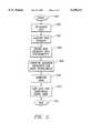
- FIG. 2is a flow diagram illustrating the manner in which the atrial defibrillator of FIG. 1 may be implemented in accordance with the present invention for reliably detecting depolarization activation waves of the heart.
- FIG. 1it illustrates a fully implantable atrial defibrillator 30 embodying the present invention shown in association with a schematically illustrated human heart 10 in need of atrial fibrillation monitoring and potential cardioversion of the atria.
- the portions of the heart 10 illustrated in FIG. 1are the right ventricle 12, the left ventricle 14, the right atrium 16, the left atrium 18, the superior vena cava 20, the coronary sinus 22, the coronary sinus ostium or opening 24, the left ventricular free wall 26, and the inferior vena cava 28.
- the term "depolarization activation waves”denotes R waves of the heart cardiac cycle which induce depolarizations of the ventricles 12 and 14.
- the atrial defibrillator 30generally includes an enclosure 32 for hermetically sealing the internal circuit elements of the atrial defibrillator, an endocardial first lead 34 and an intravascular second lead 36.
- the second lead 36may alternatively comprise two leads. A single lead is illustrated in FIG. 1 so as to not unduly complicate the figure.
- the enclosure 32 and the first and second leads 34 and 36are arranged to be implanted beneath the skin of a patient so as to render the atrial defibrillator 30 fully implantable.
- the endocardial first lead 34preferably comprises an endocardial bipolar lead having electrodes 38 and 40 arranged for establishing electrical contact with the right ventricle 12 of the heart 10.
- the electrodes 38 and 40permit bipolar sensing of depolarization activation waves in the right ventricle between a first pair of locations 38a and 40a within the right ventricle 12.
- the lead 34is fed through the superior vena cava 20, into the right atrium 16, and then into the right ventricle 12.
- a second path for lead 34could alternatively be through the inferior vena cava 28, into the right atrium 16, and then into the right ventricle 12.
- the second lead 36generally includes a first or distal electrode 42 and a second electrode 46.
- the second lead 36is flexible and arranged to be passed down the superior vena cava 20, into the right atrium 16, into the coronary sinus ostium 24, and advanced into the coronary sinus 22 of the heart near the left side thereof so that the first or distal electrode 42 is within the coronary sinus or within a coronary vein, such as the great vein of the heart (not shown) adjacent to the left ventricle 14.
- the electrode 42is preferably elongated such that the first electrode 42 is within the coronary sinus 22 or a coronary vein such as the great cardiac vein adjacent the left ventricle 14 as well as beneath the left atrium 18 near the left ventricle 14.
- the second electrode 46is preferably located within either the right atrium 16 or the superior vena cava 20 and preferably within the right atrium 16.
- the second lead 36may comprise two leads.
- one of the two leadsincludes the first electrode 42 and the other of the two leads includes the second electrode 46.
- the first electrode 42 and the second electrode 46are illustrated in FIG. 1 as combined on a single lead, the second lead 36, so as not to unduly complicate the figure.
- the first electrode 42 together with the second electrode 46 of the second lead 36provide for the delivery of defibrillating or cardioverting electrical energy to the atria. Because the first electrode 42 is located beneath the left atrium 18 near the left ventricle 14 and the second electrode 46 is within either the right atrium 16 or the superior vena cava 20 and above the coronary sinus ostium 24, the electrical energy applied between these electrodes will be substantially confined to the atria 16 and 18 of the heart 10. As a result, the electrical energy applied to the right ventricle 12 and left ventricle 14 when the atria are cardioverted or defibrillated will be minimized.
- the atrial defibrillator 30includes a first sense amplifier 50, a first R wave detector 52, a second sense amplifier 54, a second R wave detector 56, a third sense amplifier 58 and a P wave detector 60.
- the atrial defibrillator 30also includes a microprocessor 62 and a memory 64.
- the first sense amplifier 50includes a first input 66 which is coupled to electrode 38 of a first lead 34 and a second input 68 which is coupled to electrode 40 of the first lead 34.
- the first sense amplifier 50also includes a gain input 70 coupled to the microprocessor 62.
- the first sense amplifier 50amplifies the sensed electrical activity of the heart according to a variable gain received at the gain input 70 from the microprocessor, and provides at an output 72 an amplified input signal representative of the electrical activity of the heart such as depolarization activation waves sensed by the bipolar electrodes 38 and 40.
- the first sense amplifier 50may include one or more gain stages, the gain of each gain stage being independently variable by the microprocessor 62.
- the first sense amplifier 50may further include one or more filters for filtering sensed electrical activity of the heart.
- the first R wave detector 52includes an input 74 which is coupled to the output 72 of the first sense amplifier 50.
- the R wave detector 52produces an electrical output corresponding to the depolarization activation wave sensed by the first sense amplifier 50 when the amplified input signal received at the input 74 of the first R wave detector 52 exceeds a threshold.
- the R wave detector 52also includes a threshold input 76.
- the threshold input 76is coupled to the microprocessor 62 for receiving a threshold value from the microprocessor 62.
- the electrodes 38 and 40 and the first sense amplifier 50form a sensing means 51 in electrical contact with the heart for sensing electrical activity of the heart including depolarization activation waves and including amplifying means for amplifying the sensed electrical activity according to a variable gain and providing a signal corresponding to the depolarization activation wave.
- the first R wave detector 52forms an output means coupled to the sensing means for producing an electrical output corresponding to the depolarization activation wave sensed by the first sense amplifier 52 when the signal exceeds a threshold.
- the first sense amplifier 50 and the first R wave detector 52form an RV channel 55.
- the second sense amplifier 54includes a first input 78 which is coupled to the electrode 42 of the second lead 36 and a second input 80 which is coupled to electrode 38 of the first lead 34.
- the second sense amplifier 54also includes a gain input 84 coupled to the microprocessor 62 for receiving a gain value from the microprocessor 62.
- the second sense amplifier 54amplifies the sensed electrical activity of the heart according to the gain value received from the microprocessor and provides at an output 82 an amplified signal representative of the electrical activity of the heart such as depolarization activation waves sensed by electrodes 38 and 40.
- the second sense amplifier 54may include one or more gain stages, the gain of each gain stage being independently variable by the microprocessor 62.
- the second sense amplifier 54may further include one or more filters for filtering sensed electrical activity of the heart.
- the second R wave detector 56includes an input 86 for receiving the amplified signal provided from the output 82 of the second sense amplifier 54.
- the second R wave detector 56produces an electrical output at the output 88 when the amplified input signal provided at the input 86 exceeds a threshold.
- the second R wave detector 56also includes a threshold input 90 coupled to the microprocessor 62 for receiving a threshold value from the microprocessor 62.
- electrode 42, electrode 38, and sense amplifier 54form a sensing means 92 in electrical contact with the heart 10 for sensing electrical activity of the heart 10 including depolarization activation waves and including amplifying means for amplifying the sensed electrical activity according to a variable gain and providing a signal corresponding to the depolarization activation waves.
- the second R wave detector 56forms an output means coupled to the sensing means for producing an electrical output corresponding to the depolarization activation wave sensed by the sensing means when the signal exceeds a threshold.
- the second sense amplifier 54 and the second R wave detector 56form an RVCS channel 57.
- the third sense amplifier 58senses electrical activity in the atria 16 and 18 of the heart 10.
- the third sense amplifier 58includes a first input 94 which is coupled to electrode 46 and a second input 96 which is coupled to electrode 42.
- the third sense amplifier 58includes an output 100 which is coupled to an input 102 of the P wave detector 60.
- the P wave detector 60includes an output 104 for providing an indication of electrical activity of the heart sensed by the third sense amplifier 58.
- the electrodes 42 and 46 and the third sense amplifier 58form a detecting means 95 adapted for sensing activity of the heart in at least one of the atria of the heart.
- the microprocessor 62includes an atrial fibrillation detector 106, a timer 108, an automatic gain control 109, and a charge delivery control 111.
- the atrial fibrillation detector 106analyzes the electrical output of the first R wave detector 52, the second R wave detector 56 and the P wave detector 60 and the data stored in memory 64 corresponding to electrical activity of the heart sensed by first sense amplifier 50, second sense amplifier 54 and third sense amplifier 58; converted by analog-to-digital converter 112 and conveyed by direct memory access controller 114, and determines when the heart 10 is in need of cardioversion or defibrillation.
- the atrial defibrillator 30further includes an analog multiplexer 110, an analog-to-digital converter 112, and a direct memory access (DMA) controller 114.
- the output 72 of the first sense amplifier 50, the output 82 of the second sense amplifier 54, and the output 100 of the third sense amplifier 58are coupled to the analog multiplexer 110.
- the analog multiplexer 110couples signals received from either the first sense amplifier 50, the second sense amplifier 54, or the third sense amplifier 58 to the output 116 of the analog multiplexer 110.
- the output 116is coupled to the analog-to-digital converter 112, which converts analog signals received from the output 116 to digital data.
- the digital dataare conveyed over a multiple bit data bus 118 to the direct memory access controller 114.
- the direct memory access controller 114conveys the digital data, along with storage address information, over a multiple bit bus 120 to the memory 64.
- data received from either the first sense amplifier 50, the second sense amplifier 54 or the third sense amplifier 58are stored by the DMA controller 114 in the memory 64, without further intervention by the microprocessor 62.
- the atrial defibrillator 30acquires an intracardiac electrogram (EGM) segment.
- the microprocessor 62conveys control signals to the analog multiplexer 110 to cause the analog multiplexer 110 to couple either the output 72 of the first sense amplifier 50 or the output 82 of the second sense amplifier 54 or the output 100 of the third sense amplifier 58 to the output 116 of the analog multiplexer.
- the analog-to-digital converter 112converts analog signals from the output 116 to digital data.
- the DMA controller 114receives the digital data from the output 118 of the analog-to-digital converter 112 and stores the data in the memory 64.
- the atrial defibrillator 30stores data for a predetermined time duration, for example, eight seconds.
- the atrial defibrillator 30may store data corresponding to electrical activity of the heart sensed by each of the first sense amplifier 50, the second sense amplifier 54 and the third sense amplifier 58.
- the atrial fibrillation detector 106analyzes the data stored in the memory 64 to determine if the heart 10 is in need of cardioversion or defibrillation.
- the atrial defibrillator 30further includes a charger and storage capacitor circuit 122 of the type well known in the art which charges a storage capacitor to a predetermined voltage level and a discharge circuit 124 for discharging the storage capacitor within circuit 122 by a predetermined amount to provide a controlled discharge output of electrical energy when required to the atria of the heart 10.
- the discharge circuit 124is coupled to the first electrode 44 and the second electrode 46 of the second lead 36 for applying the cardioverting or defibrillating electrical energy to the atria.
- the atrial defibrillator 30further includes a depletable power source 126, such as a lithium battery, for providing power to the electrical components of the atrial defibrillator 30.
- the charge delivery control 111causes the charger and storage capacitor circuit 122 to charge the storage capacitor within circuit 122.
- the charge delivery control 111causes the discharge circuit 124 to discharge the capacitor of the circuit 122 for applying cardioverting electrical energy to the atria 16 and 18 in synchronism with an R wave detected by sense amplifier 50 and R wave detector 52 and second sense amplifier 54 and second R wave detector 56.
- the charge delivery control circuit 111responds to the timer 108 to synchronize discharge of the capacitor to a detected R wave.
- the microprocessor 62is arranged to operate in conjunction with the memory 64, which may be coupled to the microprocessor 62 by a multiple bit address and data bus 128. This permits the microprocessor 62 to address desired memory locations within the memory for executing read or write operations.
- the microprocessor 62stores data in the memory 64 at the addresses defined by multiple bit addresses conveyed over the multiple bit address and data bus 128 and conveys data to the memory 64.
- the microprocessor 62obtains data from the memory 64 at the storage locations identified by the multiple bit addresses provided over the multiple bit address and data bus 128 and receives the data from the memory 64.
- the microprocessor 62receives programmable operating parameters from an external controller 130 which is external to the skin of the patient.
- the external controller 130is arranged to communicate with a receiver/transmitter 132 within enclosure 32 which is coupled to the microprocessor 62 over a bi-directional bus 134.
- the receiver/transmitter 132may be of the type well known in the art for conveying various information which it obtains from the microprocessor 62 to the external controller 130 or for receiving programing parameters from the external controller 130 which the receiver/transmitter 132 then conveys to the microprocessor 62 for storage in internal memory or in the memory 64 within enclosure 32.
- the receiver/transmitter 132includes a transmitting coil 136.
- Such communications circuitsare well known in the art and may be utilized as noted above for receiving commands from external to the implantable enclosure 32 and for transmitting data to the external controller 130 from the implanted enclosure 32.
- the atrial defibrillator 30further includes a pace pulse delivery circuit 140.
- the pace pulse delivery circuit 140In response to signals received from the microprocessor 62, the pace pulse delivery circuit 140 generates a pacing pulse.
- the pace pulse delivery circuit 140is coupled to the electrode 38 and the electrode 40 of lead 34 for the delivery of pacing pulses to the right ventricle.
- the atrial defibrillator 30For reliably detecting the occurrence of a depolarization activation wave in the RV channel, the atrial defibrillator 30 varies the gain of the first sense amplifier 50 or the threshold of the first R wave detector 52, or both. In accordance with the present invention, the atrial defibrillator 30 varies at least one of the gain of the first sense amplifier 50 and the threshold of the first R wave detector 52 to maintain a predetermined sense margin between the amplitude of the signal sensed at the inputs 66, 68 of the first sense amplifier 50 and the gain of the first sense amplifier 50 and the threshold of the first R wave detector 52.
- the atrial defibrillator 30varies the gain of the second sense amplifier 54 or the threshold of the second R wave detector 56, or both. In accordance with the present invention, the atrial defibrillator 30 varies at least one of the gain of the second sense amplifier 54 and the threshold of the second R wave detector 56 to maintain a predetermined sense margin between the amplitude of the signal sensed at the inputs 78, 80 of the second sense amplifier 54 and the gain of the second sense amplifier 54 and the threshold of the second R wave detector 56.
- the sensitivity of a detection circuitis the minimum amplitude (in mV) of an input signal applied to the detection circuit that will cause a threshold event in the detection circuit with a fixed gain and a fixed detection threshold.
- the sense margin of the detection circuitis the ratio of the amplitude of the input signal to the sensitivity of the detection circuit. For example, in a detection circuit with a sense margin of 2:1, an input which produces a detected output has twice the amplitude necessary to cause a detection.
- the sense margin of the detection circuitdepends on both the gain of the gain stage and the threshold of the threshold detection stage.
- the sense margin of the RV channel 55depends on both the gain of the first sense amplifier 50 and the threshold of the first R wave detector 52.
- the sense margin of the RVCS channel 57depends on both the gain of the second sense amplifier 54 and the threshold of the second R wave detector 56.
- FIG. 2it is a flow diagram illustrating the manner in which the atrial defibrillator 30 of FIG. 1 may be implemented in accordance with the present invention for reliably detecting a depolarization activation wave of the heart 10.
- the methodbegins at step 200.
- the microprocessor 62sets the programmable gain in the first sense amplifier 50 to an initial gain value, for example, a minimum gain value.
- automatic gain control 109 of the microprocessor 62begins the acquisition of a digitally quantized RV electrocardiogram (EGM) segment via the DMA process.
- the microprocessor 62configures the analog multiplexer 110 to couple the output 72 of the first sense amplifier 50 to the analog-to-digital converter 112.
- the analog-to-digital converter 112converts to digital data the analog signals produced by the first sense amplifier 50.
- the DMA controller 114stores the digital data in the memory 64. Preferably, data are stored which correspond to electrical activity of the heart during a first predetermined time duration, for example, eight seconds.
- automatic gain control 109 of the microprocessor 62begins analyzing the EGM segment data stored in the memory 64.
- the automatic gain control 109divides the data stored during the predetermined time duration into data corresponding to a plurality of time segments.
- the automatic gain control 109may divide the eight-second time duration into four equal two-second time segments, W 1 , W 2 , W 3 and W 4 .
- the automatic gain control 109rectifies or determines the absolute value of the data for each of the plurality of time segments.
- the automatic gain control 109also determines the value of the peak deviation from a predetermined base line of the rectified data during each time segment of the plurality of time segments.
- the predetermined base linemay be, for example, 0 volts.
- the peak deviationscorrespond to R waves detected by the RV channel 55.
- the automatic gain control 109may compute four peak deviation values M 1 , M 2 , M 3 and M 4 for the four time segments.
- the automatic gain control 109determines a sense margin reference level by averaging a predetermined number of the peak deviations determined in step 208. Any number or combination of peak deviations of the stored data could be averaged to determine a sense margin reference level. However, in order to minimize the effects of extreme values of stored data, the automatic gain control 109 preferably determines the sense margin reference level by averaging the least of a first peak deviation determined during a first time segment and a second peak deviation determined during a second time segment, and the least of a third peak deviation determined during a third time segment and a fourth peak deviation determined during a fourth time segment.
- sense margin reference levelmay be determined according to the following equation: ##EQU1##
- the automatic gain control 109adjusts the gain of the first sense amplifier 50 and the threshold of the first R wave detector 52 so that the sense margin is maintained at a predetermined value, for example, 2:1.
- the sense marginis the ratio between the sense margin reference level, determined at step 210, and the threshold of the first R wave detector 52.
- the sense margin (SM)is determined according to the following equation: ##EQU2## Since the sense margin reference level was determined using data corresponding to electrical activity of the heart amplified by the first sense amplifier 50, the sense margin reference level is a function of the gain of the first sense amplifier 50.
- the gain and the thresholdare preferably selected using table lookup such that the sense margin is as close to 2:1 as possible without being less than 2:1.
- the methodconcludes at step 214.
- the microprocessor 62controls the atrial defibrillator 30 to acquire a new EGM segment and store data in the memory 64 corresponding to sensed electrical activity of the heart during a second predetermined time duration, for example, eight seconds.
- This datais acquired using a gain value for the first sense amplifier 50 and a threshold value for the first R wave detector 52 which have been adjusted in accordance with the method of the present invention to maintain a predetermined sense margin.
- This datamay be used, for example, by the atrial fibrillation detector 106 to determine if the heart 10 is in atrial fibrillation and in need of cardioversion or defibrillation.
- step 202After completing the method to set a first valid sense margin and acquiring an EGM segment with this valid sense margin, step 202 need not be repeated. But rather, step 204 may be executed using the gain and threshold most recently set at step 212. If the execution of steps 206-212 does not indicate a change in gain nor a change in threshold from the previous gain and previous threshold, then the EGM segment acquired by step 204 was acquired with the appropriate sense margin. This data may then be used by other analysis algorithms associated with the atria defibrillator 30, eliminating the requirement for these algorithms to acquire an additional EGM segment in such cases.
- the method illustrated in FIG. 2may also be repeated for the RVCS channel 57.
- the automatic gain control 109may adjust the gain of the second sense amplifier 54 and the threshold of the second R wave detector 56 in accordance with the method illustrated in FIG. 2.
- the method of the present inventionmay be repeated at predetermined times during operation of the atrial defibrillator 30.
- the atrial defibrillator 30may generally remain in a resting state, wherein the electrical components of the atrial defibrillator 30 are deenergized in order to conserve energy stored in the battery 116.
- the atrial defibrillator 30may change from the resting state to an awake state, during which electrical activity of the heart 10 is sensed in order to determine if the heart 10 is in need of defibrillation or cardioversion. If it is not determined that the heart 10 is in need of defibrillation or cardioversion, the atrial defibrillator 30 may return to the resting state.
- the charge delivery control 111initiates charging of the storage capacitor in the circuit 122.
- the discharge circuit 124may discharge the storage capacitor to provide cardioverting or defibrillating electrical energy to the atria of the heart 10.
- the method of the present inventionmay be repeated each time the atrial defibrillator 30 changes from the resting state to the awake state in order to recalibrate the first and second sense amplifiers 50, 54 and the first and second R wave detectors 52, 56.
- the method in accordance with the present inventionmay also be repeated after the storage capacitor is charged but just prior to delivering the cardioverting or defibrillating electrical energy to the heart, as a safety check to confirm the detected atrial fibrillation or other arrhythmia condition.
- Either the sensitivity or the sense margin of the RV channel 55 or the RVCS channel 57may be varied using the external controller 130.
- a selected sensitivity or sense margin valuemay be communicated to the receiver/transmitter 132 within the enclosure 32.
- the selected sense margin valueis then communicated by the receiver/transmitter 132 to the microprocessor 62 over the bi-directional bus 134.
- the present inventionprovides a method and apparatus for reliably detecting a depolarization activation wave of the heart by automatically adjusting either the gain of a sense amplifier or the threshold of a threshold detector to maintain a predetermined sense margin.
- the present inventionallows detection of depolarization activation waves of the heart despite wide variations in the amplitudes of the depolarization activation waves.
Landscapes
- Health & Medical Sciences (AREA)
- Life Sciences & Earth Sciences (AREA)
- Radiology & Medical Imaging (AREA)
- Cardiology (AREA)
- Heart & Thoracic Surgery (AREA)
- Engineering & Computer Science (AREA)
- Biomedical Technology (AREA)
- Nuclear Medicine, Radiotherapy & Molecular Imaging (AREA)
- Animal Behavior & Ethology (AREA)
- General Health & Medical Sciences (AREA)
- Public Health (AREA)
- Veterinary Medicine (AREA)
- Physiology (AREA)
- Biophysics (AREA)
- Electrotherapy Devices (AREA)
Abstract
Description
Claims (17)
Priority Applications (1)
| Application Number | Priority Date | Filing Date | Title |
|---|---|---|---|
| US08/213,119US5458621A (en) | 1994-03-15 | 1994-03-15 | Automatic gain control and method for enabling detection of low and high amplitude depolarization activation waves of the heart and atrial defibrillator utilizing the same |
Applications Claiming Priority (1)
| Application Number | Priority Date | Filing Date | Title |
|---|---|---|---|
| US08/213,119US5458621A (en) | 1994-03-15 | 1994-03-15 | Automatic gain control and method for enabling detection of low and high amplitude depolarization activation waves of the heart and atrial defibrillator utilizing the same |
Publications (1)
| Publication Number | Publication Date |
|---|---|
| US5458621Atrue US5458621A (en) | 1995-10-17 |
Family
ID=22793786
Family Applications (1)
| Application Number | Title | Priority Date | Filing Date |
|---|---|---|---|
| US08/213,119Expired - LifetimeUS5458621A (en) | 1994-03-15 | 1994-03-15 | Automatic gain control and method for enabling detection of low and high amplitude depolarization activation waves of the heart and atrial defibrillator utilizing the same |
Country Status (1)
| Country | Link |
|---|---|
| US (1) | US5458621A (en) |
Cited By (53)
| Publication number | Priority date | Publication date | Assignee | Title |
|---|---|---|---|---|
| US5562709A (en)* | 1995-04-18 | 1996-10-08 | Incontrol, Inc. | Atrial defibrillator having both specific and sensitive R wave detection |
| US5620466A (en)* | 1995-08-14 | 1997-04-15 | Cardiac Pacemakers, Inc. | Digital AGC using separate gain control and threshold templating |
| US5658317A (en)* | 1995-08-14 | 1997-08-19 | Cardiac Pacemakers, Inc. | Threshold templating for digital AGC |
| US5662688A (en)* | 1995-08-14 | 1997-09-02 | Cardiac Pacemakers, Inc. | Slow gain control |
| EP0770409A3 (en)* | 1995-10-19 | 1998-05-20 | INCONTROL, Inc. | An implantable atrial defibrillator and system having multiple channel electrogram telemetry and method |
| US5755765A (en)* | 1997-01-24 | 1998-05-26 | Cardiac Pacemakers, Inc. | Pacing lead having detachable positioning member |
| US5755766A (en)* | 1997-01-24 | 1998-05-26 | Cardiac Pacemakers, Inc. | Open-ended intravenous cardiac lead |
| US5800497A (en)* | 1997-07-17 | 1998-09-01 | Medtronic, Inc. | Medical electrical lead with temporarily stiff portion |
| US5803928A (en)* | 1997-01-24 | 1998-09-08 | Cardiac Pacemakers, Inc. | Side access "over the wire" pacing lead |
| WO1998046307A1 (en)* | 1997-04-14 | 1998-10-22 | Intermedics Inc. | Dynamic atrial detection sensitivity control in an implantable medical cardiac stimulator |
| WO1999039768A1 (en)* | 1998-02-06 | 1999-08-12 | Intermedics Inc. | Implantable device with digital waveform telemetry |
| WO1999040968A1 (en)* | 1998-02-17 | 1999-08-19 | Intermedics Inc. | Diagnostic test protocol in an implantable medical device |
| EP0958843A1 (en)* | 1997-04-22 | 1999-11-24 | Cardiac Pacemakers, Inc. | Automatic sensing level adjustment for implantable cardiac rhythm devices |
| US6005370A (en)* | 1998-01-26 | 1999-12-21 | Physio-Control Manufacturing Corporation | Automatic rate control for defibrillator capacitor charging |
| US6070101A (en)* | 1998-04-28 | 2000-05-30 | Medtronic, Inc. | Multiple channel, sequential, cardiac pacing systems |
| US6377844B1 (en) | 1999-03-13 | 2002-04-23 | Dave Graen | R-wave detector circuit for sensing cardiac signals |
| US20020111664A1 (en)* | 1999-09-29 | 2002-08-15 | Cardiac Pacemakers, Inc. | Low profile, ventricular, transvenous, epicardial defibrillation lead |
| US6440082B1 (en) | 1999-09-30 | 2002-08-27 | Medtronic Physio-Control Manufacturing Corp. | Method and apparatus for using heart sounds to determine the presence of a pulse |
| US6510339B2 (en)* | 2000-12-06 | 2003-01-21 | Cardiac Pacemakers, Inc. | ECG auto-gain control |
| WO2003022147A1 (en)* | 2001-09-12 | 2003-03-20 | Medtronic,Inc. | Automatic threshold generation for electrogram measurement |
| US20030100925A1 (en)* | 2001-11-28 | 2003-05-29 | Medtronic, Inc. | Implantable medical device for measuring mechanical heart function |
| US6671560B2 (en) | 1998-06-12 | 2003-12-30 | Cardiac Pacemakers, Inc. | Modified guidewire for left ventricular access lead |
| US20040039420A1 (en)* | 2002-08-26 | 2004-02-26 | Medtronic Physio-Control Manufacturing Corp. | Apparatus, software, and methods for cardiac pulse detection using accelerometer data |
| US20040116969A1 (en)* | 2002-08-26 | 2004-06-17 | Owen James M. | Pulse detection using patient physiological signals |
| US20050026594A1 (en)* | 2003-07-31 | 2005-02-03 | Miller John S. | Technique for controlling fraudulent use of a telecommunication service including information assistance |
| US20050085885A1 (en)* | 1998-08-12 | 2005-04-21 | Cardiac Pacemakers, Inc. | Expandable seal for use with medical device and system |
| US6915169B2 (en) | 1998-07-22 | 2005-07-05 | Cardiac Pacemakers, Inc. | Extendable and retractable lead having a snap-fit terminal connector |
| US6934589B2 (en) | 2000-12-29 | 2005-08-23 | Medtronic, Inc. | System and method for placing endocardial leads |
| US6983185B2 (en) | 1998-07-22 | 2006-01-03 | Cardiac Pacemakers, Inc. | Lead with terminal connector assembly |
| US20060167515A1 (en)* | 1999-09-30 | 2006-07-27 | Medtronic Emergency Response | Apparatus, software, and methods for cardiac pulse detection using a piezoelectric sensor |
| US20070288060A1 (en)* | 1999-09-30 | 2007-12-13 | Stickney Ronald E | Pulse Detection Method and Apparatus Using Patient Impedance |
| US20090157128A1 (en)* | 2007-12-12 | 2009-06-18 | Cardiac Pacemakers, Inc. | Sensing threshold control to limit amplitude tracking |
| US7620446B2 (en) | 2003-07-31 | 2009-11-17 | Medtronic, Inc. | Monitoring P-waves to detect degradation of atrial myocardium |
| US7657324B2 (en) | 1998-08-12 | 2010-02-02 | Cardiac Pacemakers, Inc. | Seal for use with cardiac lead |
| US7668593B1 (en)* | 2007-03-30 | 2010-02-23 | Pacesetter, Inc. | System and method to accelerate individualized gain adjustment in implantable medical device systems |
| US9220427B2 (en) | 2011-05-02 | 2015-12-29 | The Regents Of The University Of California | System and method for reconstructing cardiac activation information |
| US9241667B2 (en) | 2010-04-08 | 2016-01-26 | The Regents Of The University Of California | System and method for reconstructing cardiac signals associated with a complex rhythm disorder |
| US9248306B2 (en) | 1999-09-30 | 2016-02-02 | Physio-Control, Inc. | Pulse detection apparatus, software, and methods using patient physiological signals |
| US9283397B2 (en) | 2012-01-31 | 2016-03-15 | Christopher C. Stancer | Charge control for high voltage therapy energy storage component |
| US9393425B2 (en) | 2008-05-13 | 2016-07-19 | The Regents Of The University Of California | Methods and systems for detecting and treating heart instability |
| US9398883B2 (en) | 2011-05-02 | 2016-07-26 | The Regents Of The University Of California | System and method for reconstructing cardiac activation information |
| US9468387B2 (en) | 2011-05-02 | 2016-10-18 | The Regents Of The University Of California | System and method for reconstructing cardiac activation information |
| US9630018B2 (en) | 2012-01-31 | 2017-04-25 | Medtronic, Inc. | Charge control for high voltage therapy energy storage component |
| US9641012B2 (en) | 2014-04-18 | 2017-05-02 | Medtronic, Inc. | Methods, implantable medical devices, and systems that abort a high voltage charge when a transformer is impaired |
| US9655535B2 (en) | 2011-05-02 | 2017-05-23 | The Regents Of The University Of California | System and method for targeting heart rhythm disorders using shaped ablation |
| US9724009B2 (en) | 2011-12-09 | 2017-08-08 | The Regents Of The University Of California | System and method of identifying sources for biological rhythms |
| US9955879B2 (en) | 2008-10-09 | 2018-05-01 | The Regents Of The University Of California | System for analysis of complex rhythm disorders |
| US10085655B2 (en) | 2013-03-15 | 2018-10-02 | The Regents Of The University Of California | System and method to define drivers of sources associated with biological rhythm disorders |
| US10398326B2 (en) | 2013-03-15 | 2019-09-03 | The Regents Of The University Of California | System and method of identifying sources associated with biological rhythm disorders |
| WO2019175156A1 (en)* | 2018-03-13 | 2019-09-19 | Cathvision Aps | System and method for processing electrophysiological signals |
| US10434319B2 (en) | 2009-10-09 | 2019-10-08 | The Regents Of The University Of California | System and method of identifying sources associated with biological rhythm disorders |
| US12377271B2 (en) | 2011-11-04 | 2025-08-05 | Nevro Corp. | Medical device communication and charging assemblies for use with implantable signal generators, and associated systems and methods |
| US12440676B2 (en) | 2023-08-18 | 2025-10-14 | Nevro Corp. | Implanted pulse generators with reduced power consumption via signal strength/duration characteristics, and associated systems and methods |
Citations (4)
| Publication number | Priority date | Publication date | Assignee | Title |
|---|---|---|---|---|
| US5010887A (en)* | 1989-11-17 | 1991-04-30 | Siemens-Pacesetter, Inc. | Noise discrimination in implantable pacemakers |
| US5269300A (en)* | 1992-07-30 | 1993-12-14 | Cardiac Pacemakers, Inc. | Automatic sensitivity control in an implantable cardiac rhythm management system |
| US5279291A (en)* | 1991-04-12 | 1994-01-18 | Incontrol, Inc. | Method for atrial defibrillation |
| US5348021A (en)* | 1992-03-31 | 1994-09-20 | Incontrol, Inc. | Apparatus and method for reliably detecting a depolarization activation wave of the heart and atrial defibrillator utilizing same |
- 1994
- 1994-03-15USUS08/213,119patent/US5458621A/ennot_activeExpired - Lifetime
Patent Citations (4)
| Publication number | Priority date | Publication date | Assignee | Title |
|---|---|---|---|---|
| US5010887A (en)* | 1989-11-17 | 1991-04-30 | Siemens-Pacesetter, Inc. | Noise discrimination in implantable pacemakers |
| US5279291A (en)* | 1991-04-12 | 1994-01-18 | Incontrol, Inc. | Method for atrial defibrillation |
| US5348021A (en)* | 1992-03-31 | 1994-09-20 | Incontrol, Inc. | Apparatus and method for reliably detecting a depolarization activation wave of the heart and atrial defibrillator utilizing same |
| US5269300A (en)* | 1992-07-30 | 1993-12-14 | Cardiac Pacemakers, Inc. | Automatic sensitivity control in an implantable cardiac rhythm management system |
Cited By (104)
| Publication number | Priority date | Publication date | Assignee | Title |
|---|---|---|---|---|
| AU693330B2 (en)* | 1995-04-18 | 1998-06-25 | Cardiac Pacemakers, Inc. | Atrial defibrillator having both specific and sensitive R wave detection |
| US5562709A (en)* | 1995-04-18 | 1996-10-08 | Incontrol, Inc. | Atrial defibrillator having both specific and sensitive R wave detection |
| US5620466A (en)* | 1995-08-14 | 1997-04-15 | Cardiac Pacemakers, Inc. | Digital AGC using separate gain control and threshold templating |
| US5658317A (en)* | 1995-08-14 | 1997-08-19 | Cardiac Pacemakers, Inc. | Threshold templating for digital AGC |
| US5662688A (en)* | 1995-08-14 | 1997-09-02 | Cardiac Pacemakers, Inc. | Slow gain control |
| EP0770409A3 (en)* | 1995-10-19 | 1998-05-20 | INCONTROL, Inc. | An implantable atrial defibrillator and system having multiple channel electrogram telemetry and method |
| US5755766A (en)* | 1997-01-24 | 1998-05-26 | Cardiac Pacemakers, Inc. | Open-ended intravenous cardiac lead |
| US5755765A (en)* | 1997-01-24 | 1998-05-26 | Cardiac Pacemakers, Inc. | Pacing lead having detachable positioning member |
| US5803928A (en)* | 1997-01-24 | 1998-09-08 | Cardiac Pacemakers, Inc. | Side access "over the wire" pacing lead |
| WO1998046307A1 (en)* | 1997-04-14 | 1998-10-22 | Intermedics Inc. | Dynamic atrial detection sensitivity control in an implantable medical cardiac stimulator |
| EP0958843A1 (en)* | 1997-04-22 | 1999-11-24 | Cardiac Pacemakers, Inc. | Automatic sensing level adjustment for implantable cardiac rhythm devices |
| US5800497A (en)* | 1997-07-17 | 1998-09-01 | Medtronic, Inc. | Medical electrical lead with temporarily stiff portion |
| US6005370A (en)* | 1998-01-26 | 1999-12-21 | Physio-Control Manufacturing Corporation | Automatic rate control for defibrillator capacitor charging |
| WO1999039768A1 (en)* | 1998-02-06 | 1999-08-12 | Intermedics Inc. | Implantable device with digital waveform telemetry |
| US6507759B1 (en) | 1998-02-06 | 2003-01-14 | Intermedics, Inc. | Implantable device with digital waveform telemetry |
| US6959213B2 (en) | 1998-02-06 | 2005-10-25 | Intermedics, Inc. | Implantable device with digital waveform telemetry |
| US20030074036A1 (en)* | 1998-02-06 | 2003-04-17 | Intermedics Inc. | Implantable device with digital waveform telemetry |
| WO1999040968A1 (en)* | 1998-02-17 | 1999-08-19 | Intermedics Inc. | Diagnostic test protocol in an implantable medical device |
| US6070101A (en)* | 1998-04-28 | 2000-05-30 | Medtronic, Inc. | Multiple channel, sequential, cardiac pacing systems |
| US6671560B2 (en) | 1998-06-12 | 2003-12-30 | Cardiac Pacemakers, Inc. | Modified guidewire for left ventricular access lead |
| US8209035B2 (en) | 1998-07-22 | 2012-06-26 | Cardiac Pacemakers, Inc. | Extendable and retractable lead having a snap-fit terminal connector |
| US6983185B2 (en) | 1998-07-22 | 2006-01-03 | Cardiac Pacemakers, Inc. | Lead with terminal connector assembly |
| US8285398B2 (en) | 1998-07-22 | 2012-10-09 | Cardiac Pacemakers, Inc. | Lead with terminal connector assembly |
| US7774934B2 (en) | 1998-07-22 | 2010-08-17 | Cardiac Pacemakers, Inc. | Method for making a terminal connector |
| US7392095B2 (en) | 1998-07-22 | 2008-06-24 | Cardiac Pacemakers, Inc. | Extendable and retractable lead having a snap-fit terminal connector |
| US6915169B2 (en) | 1998-07-22 | 2005-07-05 | Cardiac Pacemakers, Inc. | Extendable and retractable lead having a snap-fit terminal connector |
| US7412290B2 (en) | 1998-08-12 | 2008-08-12 | Cardiac Pacemakers, Inc. | Seal for use with medical device and system |
| US7657324B2 (en) | 1998-08-12 | 2010-02-02 | Cardiac Pacemakers, Inc. | Seal for use with cardiac lead |
| US20050085885A1 (en)* | 1998-08-12 | 2005-04-21 | Cardiac Pacemakers, Inc. | Expandable seal for use with medical device and system |
| US6901288B2 (en) | 1998-08-12 | 2005-05-31 | Cardiac Pacemakers, Inc. | Sealing assembly for intravenous lead |
| US6377844B1 (en) | 1999-03-13 | 2002-04-23 | Dave Graen | R-wave detector circuit for sensing cardiac signals |
| US20020111664A1 (en)* | 1999-09-29 | 2002-08-15 | Cardiac Pacemakers, Inc. | Low profile, ventricular, transvenous, epicardial defibrillation lead |
| US9981142B2 (en) | 1999-09-30 | 2018-05-29 | Physio-Control, Inc. | Pulse detection apparatus, software, and methods using patient physiological signals |
| US8532766B2 (en) | 1999-09-30 | 2013-09-10 | Physio-Control, Inc. | Pulse detection apparatus, software, and methods using patient physiological signals |
| US6440082B1 (en) | 1999-09-30 | 2002-08-27 | Medtronic Physio-Control Manufacturing Corp. | Method and apparatus for using heart sounds to determine the presence of a pulse |
| US20050240234A1 (en)* | 1999-09-30 | 2005-10-27 | Medtronic Emergency Response Systems, Inc. | Pulse detection apparatus, software, and methods using patient physiological signals |
| US8160703B2 (en) | 1999-09-30 | 2012-04-17 | Physio-Control, Inc. | Apparatus, software, and methods for cardiac pulse detection using a piezoelectric sensor |
| US20060167515A1 (en)* | 1999-09-30 | 2006-07-27 | Medtronic Emergency Response | Apparatus, software, and methods for cardiac pulse detection using a piezoelectric sensor |
| US20070288060A1 (en)* | 1999-09-30 | 2007-12-13 | Stickney Ronald E | Pulse Detection Method and Apparatus Using Patient Impedance |
| US8239024B2 (en) | 1999-09-30 | 2012-08-07 | Physio-Control, Inc. | Pulse detection apparatus, software, and methods using patient physiological signals |
| US8092392B2 (en) | 1999-09-30 | 2012-01-10 | Physio-Control, Inc. | Pulse detection method and apparatus using patient impedance |
| US9248306B2 (en) | 1999-09-30 | 2016-02-02 | Physio-Control, Inc. | Pulse detection apparatus, software, and methods using patient physiological signals |
| US8744577B2 (en) | 1999-09-30 | 2014-06-03 | Physio-Control, Inc. | Pulse detection apparatus, software, and methods using patient physiological signals |
| US20110144708A1 (en)* | 1999-09-30 | 2011-06-16 | Physio-Control, Inc. | Pulse detection apparatus, software, and methods using patient physiological signals |
| US20030060723A1 (en)* | 1999-09-30 | 2003-03-27 | Medtronic Physio-Control Manufacturing Corp. | Pulse detection apparatus, software, and methods using patient physiological signals |
| US7917209B2 (en) | 1999-09-30 | 2011-03-29 | Physio-Control, Inc. | Pulse detection apparatus, software, and methods using patient physiological signals |
| US20100292748A9 (en)* | 1999-09-30 | 2010-11-18 | Stickney Ronald E | Pulse Detection Method and Apparatus Using Patient Impedance |
| US6510339B2 (en)* | 2000-12-06 | 2003-01-21 | Cardiac Pacemakers, Inc. | ECG auto-gain control |
| US6934589B2 (en) | 2000-12-29 | 2005-08-23 | Medtronic, Inc. | System and method for placing endocardial leads |
| WO2003022147A1 (en)* | 2001-09-12 | 2003-03-20 | Medtronic,Inc. | Automatic threshold generation for electrogram measurement |
| US6959214B2 (en)* | 2001-11-28 | 2005-10-25 | Medtronic, Inc. | Implantable medical device for measuring mechanical heart function |
| US20030100925A1 (en)* | 2001-11-28 | 2003-05-29 | Medtronic, Inc. | Implantable medical device for measuring mechanical heart function |
| US20100121392A1 (en)* | 2001-12-06 | 2010-05-13 | Medtronic Physio-Control Manufacturing | Pulse detection method and apparatus using patient impedance |
| US20100121208A1 (en)* | 2001-12-06 | 2010-05-13 | Medtronic Physio-Control Manufacturing Corp. | Pulse detection method and apparatus using patient impedance |
| US20100114219A1 (en)* | 2001-12-06 | 2010-05-06 | Medtronic Physio-Control, Manufacturing Corp. | Pulse detection method and apparatus using patient impedance |
| US8663121B2 (en) | 2001-12-06 | 2014-03-04 | Physio-Control, Inc. | Pulse detection method and apparatus using patient impedance |
| US9950178B2 (en) | 2001-12-06 | 2018-04-24 | Physio-Control, Inc. | Pulse detection method and apparatus using patient impedance |
| US20040039420A1 (en)* | 2002-08-26 | 2004-02-26 | Medtronic Physio-Control Manufacturing Corp. | Apparatus, software, and methods for cardiac pulse detection using accelerometer data |
| US8135462B2 (en) | 2002-08-26 | 2012-03-13 | Physio-Control, Inc. | Pulse detection using patient physiological signals |
| US20040116969A1 (en)* | 2002-08-26 | 2004-06-17 | Owen James M. | Pulse detection using patient physiological signals |
| US8591425B2 (en) | 2002-08-26 | 2013-11-26 | Physio-Control, Inc. | Pulse detection using patient physiological signals |
| US8992432B2 (en) | 2002-08-26 | 2015-03-31 | Physio-Control, Inc. | Pulse detection using patient physiological signals |
| US9216001B2 (en) | 2002-08-26 | 2015-12-22 | Physio-Control, Inc. | Pulse detection using patient physiological signals |
| US11045100B2 (en) | 2002-08-26 | 2021-06-29 | West Affum Holdings Corp. | Pulse detection using patient physiological signals |
| US20080208273A1 (en)* | 2002-08-26 | 2008-08-28 | Owen James M | Pulse Detection Using Patient Physiological Signals |
| US7620446B2 (en) | 2003-07-31 | 2009-11-17 | Medtronic, Inc. | Monitoring P-waves to detect degradation of atrial myocardium |
| US20050026594A1 (en)* | 2003-07-31 | 2005-02-03 | Miller John S. | Technique for controlling fraudulent use of a telecommunication service including information assistance |
| US11419508B2 (en) | 2003-09-02 | 2022-08-23 | West Affum Holdings Dac | Pulse detection using patient physiological signals |
| US7668593B1 (en)* | 2007-03-30 | 2010-02-23 | Pacesetter, Inc. | System and method to accelerate individualized gain adjustment in implantable medical device systems |
| US20090157128A1 (en)* | 2007-12-12 | 2009-06-18 | Cardiac Pacemakers, Inc. | Sensing threshold control to limit amplitude tracking |
| US8340768B2 (en) | 2007-12-12 | 2012-12-25 | Cardiac Pacemakers, Inc. | Sensing threshold control to limit amplitude tracking |
| US9393425B2 (en) | 2008-05-13 | 2016-07-19 | The Regents Of The University Of California | Methods and systems for detecting and treating heart instability |
| US10136860B2 (en) | 2008-05-13 | 2018-11-27 | The Regents Of The University Of California | System for detecting and treating heart instability |
| US10092196B2 (en) | 2008-10-09 | 2018-10-09 | The Regents Of The University Of California | Method for analysis of complex rhythm disorders |
| US11147462B2 (en) | 2008-10-09 | 2021-10-19 | The Regents Of The University Of California | Method for analysis of complex rhythm disorders |
| US9955879B2 (en) | 2008-10-09 | 2018-05-01 | The Regents Of The University Of California | System for analysis of complex rhythm disorders |
| US10434319B2 (en) | 2009-10-09 | 2019-10-08 | The Regents Of The University Of California | System and method of identifying sources associated with biological rhythm disorders |
| US10856760B2 (en) | 2010-04-08 | 2020-12-08 | The Regents Of The University Of California | Method and system for detection of biological rhythm disorders |
| US9549684B2 (en) | 2010-04-08 | 2017-01-24 | The Regents Of The University Of California | System and method for reconstructing cardiac signals associated with a complex rhythm disorder |
| US9241667B2 (en) | 2010-04-08 | 2016-01-26 | The Regents Of The University Of California | System and method for reconstructing cardiac signals associated with a complex rhythm disorder |
| US9717436B2 (en) | 2010-04-08 | 2017-08-01 | The Regents Of The University Of California | Method and system for detection of biological rhythm disorders |
| US9220427B2 (en) | 2011-05-02 | 2015-12-29 | The Regents Of The University Of California | System and method for reconstructing cardiac activation information |
| US9913615B2 (en) | 2011-05-02 | 2018-03-13 | The Regents Of The University Of California | System and method for reconstructing cardiac activation information |
| US9668666B2 (en) | 2011-05-02 | 2017-06-06 | The Regents Of The University Of California | System and method for reconstructing cardiac activation information |
| US9655535B2 (en) | 2011-05-02 | 2017-05-23 | The Regents Of The University Of California | System and method for targeting heart rhythm disorders using shaped ablation |
| US9468387B2 (en) | 2011-05-02 | 2016-10-18 | The Regents Of The University Of California | System and method for reconstructing cardiac activation information |
| US10149622B2 (en) | 2011-05-02 | 2018-12-11 | The Regents Of The University Of California | System and method for reconstructing cardiac activation information |
| US10271786B2 (en) | 2011-05-02 | 2019-04-30 | The Regents Of The University Of California | System and method for reconstructing cardiac activation information |
| US9398883B2 (en) | 2011-05-02 | 2016-07-26 | The Regents Of The University Of California | System and method for reconstructing cardiac activation information |
| US10485438B2 (en) | 2011-05-02 | 2019-11-26 | The Regents Of The University Of California | System and method for targeting heart rhythm disorders using shaped ablation |
| US12377271B2 (en) | 2011-11-04 | 2025-08-05 | Nevro Corp. | Medical device communication and charging assemblies for use with implantable signal generators, and associated systems and methods |
| US9724009B2 (en) | 2011-12-09 | 2017-08-08 | The Regents Of The University Of California | System and method of identifying sources for biological rhythms |
| US10058262B2 (en) | 2011-12-09 | 2018-08-28 | The Regents Of The University Of California | System and method of identifying sources for biological rhythms |
| US9283397B2 (en) | 2012-01-31 | 2016-03-15 | Christopher C. Stancer | Charge control for high voltage therapy energy storage component |
| US9630018B2 (en) | 2012-01-31 | 2017-04-25 | Medtronic, Inc. | Charge control for high voltage therapy energy storage component |
| US10398326B2 (en) | 2013-03-15 | 2019-09-03 | The Regents Of The University Of California | System and method of identifying sources associated with biological rhythm disorders |
| US10271744B2 (en) | 2013-03-15 | 2019-04-30 | The Regents Of The University Of California | System and method to identify sources associated with biological rhythm disorders |
| US10098560B2 (en) | 2013-03-15 | 2018-10-16 | The Regents Of The University Of California | System and method to identify sources associated with biological rhythm disorders |
| US10085655B2 (en) | 2013-03-15 | 2018-10-02 | The Regents Of The University Of California | System and method to define drivers of sources associated with biological rhythm disorders |
| US11446506B2 (en) | 2013-03-15 | 2022-09-20 | The Regents Of The University Of California | System and method of identifying sources associated with biological rhythm disorders |
| US9641012B2 (en) | 2014-04-18 | 2017-05-02 | Medtronic, Inc. | Methods, implantable medical devices, and systems that abort a high voltage charge when a transformer is impaired |
| WO2019175156A1 (en)* | 2018-03-13 | 2019-09-19 | Cathvision Aps | System and method for processing electrophysiological signals |
| US11737698B2 (en) | 2018-03-13 | 2023-08-29 | Cathvision Aps | System and method for processing electrophysiological signals |
| US12440676B2 (en) | 2023-08-18 | 2025-10-14 | Nevro Corp. | Implanted pulse generators with reduced power consumption via signal strength/duration characteristics, and associated systems and methods |
Similar Documents
| Publication | Publication Date | Title |
|---|---|---|
| US5458621A (en) | Automatic gain control and method for enabling detection of low and high amplitude depolarization activation waves of the heart and atrial defibrillator utilizing the same | |
| CA2095688C (en) | Atrial defibrillator and method for providing interval timing prior to cardioversion | |
| EP0594271B1 (en) | Atrial defibrillator for providing synchronized delayed cardioversion | |
| US6047210A (en) | Cardioverter and method for cardioverting an atrial tachyarrhythmia while maintaining atrial pacing | |
| CA2154727C (en) | Atrial defibrillator and method for providing interval timing of successive intervals prior to cardioversion | |
| EP0594274B1 (en) | Atrial defibrillator and means for providing precardio-version pacing | |
| US5282837A (en) | Atrial defibrillator and method | |
| US5265600A (en) | Atrial defibrillator and method for providing post-cardioversion pacing | |
| US5991657A (en) | Atrial cardioverter with window based atrial tachyarrhythmia detection system and method | |
| US5584864A (en) | Cardioversion synchronization system and method for an atrial defibrillator | |
| EP0627240B1 (en) | Atrial defibrillator for providing T wave detection and interval timing prior to cardioversion | |
| US5348021A (en) | Apparatus and method for reliably detecting a depolarization activation wave of the heart and atrial defibrillator utilizing same | |
| EP0594273B1 (en) | Atrial defibrillator for providing improved atrial sensing | |
| US6249699B1 (en) | Cardioverter and method for cardioverting an atrial tachyarrhythmia in the presence of atrial pacing | |
| EP0603988A2 (en) | Atrial defibrillator and method for providing pre-cardioversion warning | |
| US5441519A (en) | Implantable atrial defibrillator having delayed intervention therapy | |
| EP0738522B1 (en) | Atrial defibrillator having both specific and sensitive R wave detection |
Legal Events
| Date | Code | Title | Description |
|---|---|---|---|
| AS | Assignment | Owner name:INCONTROL, INC., WASHINGTON Free format text:ASSIGNMENT OF ASSIGNORS INTEREST;ASSIGNORS:WHITE, HARLEY;BOCEK, JOSEPH M.;REEL/FRAME:006913/0701 Effective date:19940311 | |
| STCF | Information on status: patent grant | Free format text:PATENTED CASE | |
| CC | Certificate of correction | ||
| FEPP | Fee payment procedure | Free format text:PAYOR NUMBER ASSIGNED (ORIGINAL EVENT CODE: ASPN); ENTITY STATUS OF PATENT OWNER: LARGE ENTITY Free format text:PAT HLDR NO LONGER CLAIMS SMALL ENT STAT AS SMALL BUSINESS (ORIGINAL EVENT CODE: LSM2); ENTITY STATUS OF PATENT OWNER: LARGE ENTITY | |
| REFU | Refund | Free format text:REFUND - PAYMENT OF MAINTENANCE FEE, 4TH YR, SMALL ENTITY (ORIGINAL EVENT CODE: R283); ENTITY STATUS OF PATENT OWNER: LARGE ENTITY | |
| AS | Assignment | Owner name:CARDIAC PACEMAKERS, INC., MINNESOTA Free format text:ASSIGNMENT OF ASSIGNORS INTEREST;ASSIGNOR:INCONTROL, INC.;REEL/FRAME:009781/0901 Effective date:19990202 | |
| FPAY | Fee payment | Year of fee payment:4 | |
| SULP | Surcharge for late payment | ||
| FPAY | Fee payment | Year of fee payment:8 | |
| FPAY | Fee payment | Year of fee payment:12 |