US5458209A - Device, system and method for drilling and completing a lateral well - Google Patents
Device, system and method for drilling and completing a lateral wellDownload PDFInfo
- Publication number
- US5458209A US5458209AUS08/074,475US7447593AUS5458209AUS 5458209 AUS5458209 AUS 5458209AUS 7447593 AUS7447593 AUS 7447593AUS 5458209 AUS5458209 AUS 5458209A
- Authority
- US
- United States
- Prior art keywords
- lateral
- casing string
- guide means
- well
- main
- Prior art date
- Legal status (The legal status is an assumption and is not a legal conclusion. Google has not performed a legal analysis and makes no representation as to the accuracy of the status listed.)
- Expired - Lifetime
Links
Images


Classifications
- E—FIXED CONSTRUCTIONS
- E21—EARTH OR ROCK DRILLING; MINING
- E21B—EARTH OR ROCK DRILLING; OBTAINING OIL, GAS, WATER, SOLUBLE OR MELTABLE MATERIALS OR A SLURRY OF MINERALS FROM WELLS
- E21B7/00—Special methods or apparatus for drilling
- E21B7/04—Directional drilling
- E21B7/06—Deflecting the direction of boreholes
- E21B7/061—Deflecting the direction of boreholes the tool shaft advancing relative to a guide, e.g. a curved tube or a whipstock
Definitions
- the present inventiondetails a system which is adapted to drill and complete a lateral well with respect to a main well.
- the main wellmay exhibit any inclination and may notably be substantially vertical or strongly inclined.
- This main wellmay be an open hole well, that is to say uncased, or cased by a casing string.
- the wellIn the first case, the well generally has to be plugged at the depth at which point the lateral drilling is to be initiated. This may be achieved by setting a cement plug which will provide the support necessary for a directional drill string to begin lateral drilling.
- This drill stringis conventionally equipped with a downhole motor and a deflection tool, such as a bent sub. It is also possible to perform a rotary drilling operation by using a deflection device commonly called a "whipstock", which is fastened to, or fixed in place of the plug.
- side track operationsThe object of these procedures, known as “side track” operations, is generally to abandon the lower part of the main well located at a lower level than said the plug or "whipstock".
- completion of the new Wellwill be conventional, that is to say, the casing is either run to surface or is suspended in an existing string through well-known means, for example by use of the hanging device commonly known as a "liner hanger”.
- U.S. Pat. No. 4,807,704mentions a known system and method for completing several laterals from a main well, but the equipment of the main and of the lateral well is complex and restricts the inner space of the main well, making any access to the lower part of the main well impossible. Moreover, drilling the lateral well requires a stage of milling in the casing string of the main well.
- U.S. Pat. No. 4,852,666mentions a known device and method for drilling lateral wells with respect to a horizontal drain. However, this document does not disclose a technique allowing lateral wells to be drilled from a main well which is already cased. Besides, it does not allow the lateral well to be completed with a casing.
- the present inventionconcerns a connecting device for linking two casing elements together, wherein a first casing element has a lateral opening of a dimension adapted to allow passage of a second casing element and the second casing element extends laterally from the first casing element after passage through the first casing element, with the device comprising a tie-in means for linking the second casing element to the first casing element located on the periphery of the first casing element.
- another object of the inventionis a system for drilling and completing a well extending laterally with respect to a main well, with the system comprising a casing string in the main well, said string having at least one tubular portion equipped with a lateral opening and means for at least partially closing the opening.
- the inventionalso concerns a method for drilling and completing lateral wells from a main well cased by a casing string comprising at least one lateral opening, with the method comprising the steps of positioning, in the casing string, guide means substantially at the level of the at least one lateral opening, introducing lateral drilling means through the at least one lateral opening via the guide means to drill a lateral well extending from the main well, providing the lateral well with a lateral casing string, and connecting the lateral casing string substantially on a periphery of the casing string.
- It is another object of the invention to provide a method for drilling and completing lateral wells from the main well cased by a casing stringcomprising the steps of fitting the main well with a casing string having at least one tubular portion comprising at least one lateral opening, orienting the direction of the at least one lateral opening by applying the rotation to the casing string from the surface, and controlling the direction of the at least one opening by a measuring tool.
- the object of the present inventionis notably to case a main well with a casing string comprising one or several lateral openings, which would be at least partly prepared before the casing operation, then to hang therein a lateral string introduced into a lateral well drilled from one of the openings.
- tubular elements assembled as it is introduced into the welltubular elements that are specifically manufactured, notably comprising a lateral opening, are used.
- a conventional casing operationis achieved but while placing, at the desired position, the specific elements comprising the lateral opening, as well as other drilling and completion devices.
- the main wellis thus equipped With a mixed casing comprising, at the locations predetermined by the operators, the lateral drilling and completion devices ready for use.
- the access to the inner space of the casingwill still allow servicing operations which the man skilled in the art may wish to carry out in such a well.
- the inner space of the casing prepared according to the present inventionwill allow passage of tools. It is thus possible to have access to the inner part of the casing, below the lateral drilling zone, with tools which have a conventional maximum outside diameter with respect to the inside diameter of the main casing. The drilling and the completion of the lateral drains distributed over the length of the main casing may thus be achieved with tools and equipment of equal dimension since substantially no obstacle obstructs the inner passageway of the main casing.
- the method for completing the main well according to the inventionshows great flexibility in its use, since several production stages can be planned:
- the main wellcan be put on production alone in a typical fashion using conventional production, bringing in or measuring procedures since there are no obstructions in the casing.
- One or several lateral wellsmay then be drilled by using the specific equipment installed with the casing, by using the production data acquired during a previous stage.
- This production schemeis one example of many possibilities which can be achieved with the present invention.
- the openingsmay be sealed prior to being run in the wellbore. This will allow completion of a conventional cementing operation.
- bandsnotably made of thermosetting composite material which may comprise reinforcing fibers embedded in a matrix.
- a part made of aluminum or any other drillable materialmay be placed on the opening so that its sealing through the bands may withstand higher pressures.
- a drill bit of a conventional type, used for lateral drilling,can drill through these bands and their reinforcements without imposing any additional operation. Drilling can thus be carried on after drilling through the band, without changing the tool.
- a preferred method according to the inventionmay proceede in the following stages.
- the stages described hereundershould begin at the point where a casing comprising at least one specific opening has been installed in the main well.
- Guide meanscomprising a guiding ramp similar to that of a whipstock are taken down into the main casing, by means of maneuvering rods, such as drillstring or drillpipe.
- the guide meansare advantageously designed to allow complete flexibility for their placement close to any one of the lateral openings, when there are several of them. The operator may thus choose any opening of the casing to carry out the lateral drilling and improve the production.
- the guide meansmay be used both as a deflection tool for the drill bit, and as a means for positioning the casing string installed in the lateral well.
- the drill stringis conventionally that which is used by operators with a deflection tool such as a whipstock, that is to say notably comprising a drill bit, a downhole motor, drill collars, drillpipe.
- a deflection toolsuch as a whipstock, that is to say notably comprising a drill bit, a downhole motor, drill collars, drillpipe.
- the operatorcan decide whether or not to equip the lateral well with a casing which some portions of it could be blank, perforated or not. If the completion is achieved after drilling, as it is often the case, in order to limit the risks of bridging the well through a sloughing of the formation, the same guide means are preferably used to guide the lateral casing string into the lateral well.
- the upper end of the lateral casing and the openingcomprise means for ensuring the tie-in of the lateral casing to the main casing at the level of the opening.
- These tie-in meansmay comprise a connecting sub adapted to co-operate with the opening. This sub is fastened to the upper end of the lateral casing.
- the inventionis notably advantageous in that it does not inhibit large restriction of the inner space of the main casing through the tie-in means between the lateral casing and the main casing, which allows access to the other openings located further from the surface, even after completion of the lateral well with the lateral casing.
- closing meansfor example a sliding gate, may complete the tie-in means.
- This gateis adapted for practically obstructing the total space between the connecting sub of the lateral casing and the opening, so that the effluent coming from the lateral well flows into the main casing through the inside of the lateral casing and not through the annular space between the well and the casing. In fact, if this were not the case, installing a string in the lateral well would be questionable.
- the purpose of the gatemay also be to hold the connecting sub on the casing of the main well through the co-operation of fastening or tie-in means integrated to the sub with the gate.
- the purpose of the running tool for setting the lateral casingmay advantageously be to properly position the special sub with respect to the opening and to close the gate. These two operations may of course be achieved with different tools.
- FIG. 1schematically illustrates a main well and a lateral well equipped with casing sting
- FIGS. 2A and 2Bare fragmentary cross-sectional views of the tabular portion of the main string comprising at least one lateral opening, the guiding device and the sub for connecting the lateral string;
- FIGS. 3A, 3B and 3Care views of a lower end of the guiding device
- FIG. 3D and 3Eillustrate another embodiment of an anchoring of the guiding device
- FIGS. 4A, 4B and 4Care views of a tubular portion comprising the at least one lateral opening
- FIG. 4Dillustrates a sealing gate around the connecting sub
- FIGS. 5A and 5Billustrate an upper end of the guiding device of the present invention
- FIGS. 6A and 6Billustrate a connecting sub
- FIGS. 6C, 6D and 6Eillustrate another embodiment of a connecting sub-in accordance with the present invention
- FIG. 6Fis a perspective view of a connecting sub assembled to a running tool
- FIGS. 7A, 7B and 7Care schematic views in a main string of the guiding device, the lateral well, and the taking down of the lateral string into the lateral well, respectively;
- FIGS. 8A and 8Bschematically illustrate preferred applications according to the present invention
- FIG. 9Ais a partial cross-sectional view of a running tool for setting the lateral string
- FIG. 9Bis a cross-sectional view of the system for fastening the running tool in the connecting sub
- FIGS. 10A, 10B and 10Care cross-sectional views of a device for closing a gate
- FIGS. 11A, 11B and 11Care cross-sectional views of a sealing of the casing portion comprising the at least one opening;
- FIG. 12is a cross-sectional view of a principle of a locking of the gate after closing
- FIG. 13is a partial cross-sectional view of a flexible and rotary joint linking the connecting sub to the pipes of the lateral casing;
- FIG. 14is a cross-sectional view of a connecting device between a casing portion comprising an opening and a casing pipe of the main well;
- FIGS. 15A, 15B and 15Care schematic views of a preferred embodiment of the tubular part comprising an opening and the gate.
- FIGS. 16A and 16Bare partial cross-sectional schematic views of a variant of the sealing means in accordance with the present invention.
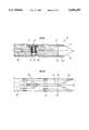
- FIG. 1a main well 1 and a lateral well 2 respectively having casing strings 4, 3 installed therein.
- An assembly 5mainly comprises a lateral opening 21 in the casing string 4, a connecting sub 7, between the main string 4 and the lateral string 3, an intermediate joint 8 between the connecting sub 7 and the casing string 3, means 9 for closing a space between the connecting sub 7 and the opening 21.
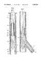
- FIGS. 2A and 2Billustrate a fragmentary cross-section of the main string 4 in which the guide means 10 are positioned, detailing how the system should be laid out for the operation of drilling or for completion of the lateral well.
- Connecting sub 7is shown in FIG. 2A fastened through stop motion and hold-back means 14, and a sliding gate 12 closes the lateral opening 21 around the connecting sub 7. Details of the gate 12 and of the opening 21 will be described more fully herein below in connection with FIGS. 4A, 4B, 4C, 4D or 15A, 15B and 15C.
- FIG. 2Athat the end 13 of the connecting sub 7 does not intrude inside the casing string 4 and lies substantially in the same plane as the opening 21. Details of the connecting sub will be described more fully hereinbelow in connection with FIGS. 6A, 6B, 6C, 6D and 6E.
- the gate 12is held on the casing string 4 by a housing or cap 16.
- a shear pin 17fastens the gate 12 in an upper or open position, a position in which the opening 12 has a dimension which allows the drill bit and the lateral casing string 3 to pass through.
- the shear pin 17is sheared and the gate 12 is in the closed position on opening 21, around the connecting sub 7.
- the guide meansare comprised of three main parts; namely, a lower end 11, detailed in FIGS. 3A, 3B, 3C, 3D and 3E; a central part comprising a ramp (FIG. 2A) whose face is oriented toward the opening 21.
- An angle I (FIG. 2A), formed by the ramp 15 with respect to the longitudinal axis,is preferably equal to or ranges between 1° and 5°, although the value of the angle formed by the ramp 15 is not limitative of the scope of the present invention, particularly, the ramp 15 can be made progressive through angles of slope increasing from 1° to 5°; and an upper end (FIG. 2B) comprising a preferably cylindrical inner passageway 22 (FIG.
- FIGS. 5A and 5Bmore fully describe the various components.
- a channel or conduit 36(FIGS. 2A, 3B, 3E, 3D), provided in the guide means 10, communicates the inner space of the casing string 4 on either side of the guide means 10.
- Centering parts 70(FIGS. 2B, 3D, 5B) are arranged on the circumference of the guide means 10, specifically at the level of the lower end 11 and the upper end 18.
- FIG. 4Ashows a top view of a tubular element 24 intended to be assembled with other tubes to form the casing string 4.
- the assemblingis achieved by threads 25 and 26 (FIG. 4B).
- Opening 21actually includes two windows 27 and 28, respectively cut out in the housing or cap 16 and the tubular body of the tubular element 24.
- the purpose of the cap 16is to maintain and guide the sliding gate 12 shown in top view in FIG. 4D.
- the width of the opening 21is adapted to permit a lateral drill bit to pass through, with the length of the opening 21 depending upon the slope of the ramp 15.
- the planar surface 29, which is part of a periphery of the window 27 of the cap 16,is the place where the connecting sub 7 lands and is fixed in place.
- a key 23is welded on the body of the tubular element 24, preferably, along the longitudinal axis of the opening 21.
- the key 23sticks out of the inner wall of the tubular element 24 so that the top of the flat part of the key 23 is located at a distance D from the diametrically opposite point.
- the value for the distance Dis functionally significant for the positioning of the guiding means 10, this function being assigned to the key 23, which is integral with the tubular element 24. Besides, this value for the distance D is sufficient not to hinder passage of a servicing part.
- Gate 12is fixed in an open position by shear pin 17 and, in this position, the opening 21 has maximum dimensions.
- FIG. 4Cis a cross-section of the tubular element 24 which shows the configuration of the gate 12 on the body of the tubular element 24 and the assembling of the cap 16 on this body through the welding of two rods 30, 31 over the total length.
- the greatest outer diametral dimensions of the tubular element 24will, preferably, not be larger than an outside diameter of a collar of the couplings of the pipes forming the casing string 4.
- the tubular element 24may be lowered into a borehole drilled by a tool of conventional diameter, without causing frictions higher than those created by a pipe coupling.
- FIG. 4Dis a view of the plate constituting the gate 12. Bore 32 receives the shear pin 17. The branches 33, 34 separated by a distance 35 will substantially close the clearance between the opening 21 and the connecting sub 7. The U-shape and width of the distance 35 depends upon the outer shape of the connecting sub 7. It should be noted that the U-shape of the window in the gate 12, when the gate 12 is closed, cooperates with the planar surface 29 forming a periphery of the window 27 of the cap 16, so as to form a rectangle of substantially equal dimensions with the section of the end of the connecting sub 7. In fact, referring to FIGS.
- FIG. 6Adiagrammatically show the connecting sub of a square cross section
- the section 13 (FIG. 6A) of the end of the connecting sub 7has a rectangular shape corresponding to the U-shape opening of the gate 12 and to the width of the planar surface 29 forming the periphery of the window 27.
- the gate 12 and the peripheral portion of the opening 21will be adapted so as to leave a limited space or even no space between the connecting sub 7 and the tubular element 24 once the gate 12 is closed on the connecting sub 7.
- the purpose of the cooperation of the gate 12 with the connecting sub 7is to provide a seal sufficient to prevent fluid from flowing around the connecting sub 7.
- a resilient jointmay be added either on the connecting sub 7 or on the gate 12 and the planar surface 29, or on both, so as to improve the effect of the seal.
- Bores 75are machined in the gate 12.
- the shape of the bores 75is adapted for cooperation with a means for displacing the gates 12, with this displacing means being part of the running tool.
- the finger 76 of the running toolshown in FIGS. 10A, 10B and 10C, illustrate, for example, this displacing.
- FIGS. 10A, 10B and 10Cillustrate, for example, this displacing.
- several bores 75are necessary and spaced out at most by a length of the displacement of the finger 76.
- Bores 75must fit a slot 66 of the body of the tubular element 24 so as to allow the gate 12 to be actuated from the inside of the casing string 4, through the wall of the tubular element 24.
- FIGS. 15A, 15B and 15Cshow another embodiment of a tubular element 24 and another design of the gate 12.
- FIGS. 15A and 15Bmainly differ in the shape of the first and second windows 27 and 28, respectively, in the cap 16 and the tubular element 24, with the coincidence of the windows 27, 28 defining the opening 21.
- the wide part 136 of the window 27narrows in the shape of a funnel and eventually has, at 138, substantially the width of the connecting sub 7.
- wings 139 of the connecting sub 7are locked by the cap 16 substantially in the zones 140, below which the tubular element 24 is open by the opening 28.
- the section of the part 135 welded on the tubular element 24has the shape of a tooth whose slope allows displacement of the connecting sub 7 in the direction of introduction into the lateral well, but it blocks displacement of the connecting sub 7 when the part 141 of the connecting sub 7 has reached its end position.
- FIG. 6Cshows the cooperation of the part 135 with the part 141 linked to the connecting sub, and after the connecting sub 7 has been set with respect to the opening 21.
- One or several shear pins 134are fixed in the cap 16 between the branches 33 and 34 of the gate 12, the gate 12 being in an open position.
- a series of pins 134may be arranged along the axis of the U-shaped portion of the gate 12.
- the purpose of the pins 134is the following: when the means for closing the gate shear pin 17, the gate 12 is driven in translation until the bottom of the U-shaped portion of the gate 12 locks against the pins 134.
- the closing meansthen warn the surface of a blocking in translation by a rise in hydraulic pressure, if the means are activated hydraulically, or by an increase in mechanical stress (for example, torque), if they are activated mechanically.
- the operatorthus knows that the gate 12 has been moved by the distance between the initial position of the gate 12 and the pins 134. By placing a succession of series of pins 134, the operator may deduce, from the surface, the position reached by the gate 12.
- FIG. 15Cis a topview of a gate 12 comprising branches 33 and 34 separated by a distance 35.
- the end 200 of branches 33 and 34has a pointed tip so as to facilitate guiding with respect to connecting sub 7.
- the gateis indented so as to form notches 142 favoring the sliding in translation of the gate 12. On one of the notches 142, teeth intended for locking the gate 12 in a closed position around the connecting sub 7 have been machined. Details of this lock are shown in FIG. 12.
- FIG. 12shows the principle of a locking of gate 12 in a closed position.
- a flexible leaf 144is fixed on at least one of the rods 30 and 31 used for the lateral guiding of the gate 12 and for fastening the cap 16 on the tubular body 24.
- the end 145 of leaf 144is suited for co-operating with teeth 143 when the gate 12 has been made to perform its total displacement.
- the dissymmetrical shape of the teeth 143locks the gate 12 irreversibly once the end 145 of the leaf 144 is engaged in one of the teeth 143.
- bores 75which purpose is identical to those of FIG. 4D, have an oblong shape and a relatively large surface so as to admit a certain tolerance of positioning of the gate 12 with respect to the finger 76 of the means for displacing the gate, a well as a mechanical reinforcement of this finger.
- FIGS. 3A, 3B and 3Cshow in detail the end 11 of guide means 10.
- FIG. 3Bis a cross-section of the means when they are positioned and anchored in pipe 4 through the cooperation of a key 23 and a groove 37.
- Groove 37comprises a pawl 38 borne by a flexible leaf 45 integral with a slide valve 40 which can slide into the housing 41 parallel to, and arranged below, the groove 37.
- a return spring 42 of the slide valve 40is held in housing 41 by a stopper 43.
- Pawl 38has a slope 44 on the side opposite the bottom 39 of groove 37, with respect to the edge 47 defined hereafter.
- the flexibility of leaf 45keeps pawl 38 prominent with respect to the bottom of the groove, through an opening 46 between housing 41 and groove 37.
- An edge or a bearing surface 47 of the pawllocks the key 23 in the housing defined by the bottom 39 of groove 37 and edge 47.
- the edge 47abuts the on key 23
- an edge 48 of opening 46co-operates with the slope 44 of the pawl so as to retract pawl 38 and releases the guide means 10 from the key 23.
- Groove 37has an open end.
- the open end, opposite the bottom 39 of groove 37,opens onto a plane surface 49 forming a face of the point of end 11.
- Another plane surface 50forms the other side of the point.
- These two plane surfaces 49 and 50belong to a dihedron.
- the point formed by surfaces 49 and 50constitutes the means for orientation of the guide means 10 with respect to the key 23 which must, depending on the case, enter groove 37 or a groove 51 diametrically opposite to the groove 37.
- Groove 51is provided over total length of a means 10 so that, when the key 23 is guided in the groove 51, the guide means 10 do not anchor and may be displaced either towards the bottom of the well, or towards the surface, while going from one side of the key 23 to the other.
- the double bevelled shape of the end 11 of guide means 10, obtained through surfaces 49 and 50,is a preferred embodiment since it can be easily achieved. But only the periphery of surfaces 49 and 50 is functional since end 11 co-operates with key 23 for guiding and orienting. Ramps for guiding the key in the groove 37, or in the groove 51, may be achieved differently for equivalent results, without departing from the scope of the invention.
- FIGS. 3D and 3Eillustrate another embodiment of the means for anchoring the guide means 10 in the casing string 4.
- the means for orienting the guide means with respect to key 23remain identical, as well as the lay-out of grooves 37 and 51.
- the reversible means for locking the key 23 in the bottom of groove 37includes a button 77 located in a housing such as a bore 78 machined radially with respect to the guide means 23, perpendicular to the axis of groove 37. Button 77 is held by a nut 79 and it is pushed in the direction of groove 37 by a stack of Belleville type spring washers 80. The necessary force to compress the button 77 in the opposite direction, could be adjustable by number and type of spring washers.
- the upper shape 81 of the button 77obstructs the groove 37, preventing displacement of the end 11 with respect to the key 23 as long as the tensile stress on the guide means 10 is not sufficient to compress the washers 80.
- Shape 81advantageously slopes down towards the groove bottom and towards the opening of the groove 37.
- conduit 36which has the same axis as end 11, terminates before the housing 78.
- Conduit 36is extended up to the end of the guide means by conduits 82 and 83 parallel to the axis of the guide means 10 and arranged on either side of housing 78 in order not to interfere with the housing 78.
- the double-pointed endis not substantially solid, but pierced with a cylindrical hole of a diameter referenced 133 and whose bottom is referenced 132.
- conduits 82 and 83open into the bottom 132.
- FIGS. 5A and 5Brelate to the upper end 18 of the guide means 10.
- This partis preferably tubular, with an outside diameter compatible with the inside diameter of the main string and with the value D (FIG. 4B), and has an inner passageway 22 of a diameter compatible with the diameter of the lateral drill bit.
- Conduit 22opens onto the inlet of the ramp 15.
- the end of part 18has the shape of a bevel 20 forming a means for guiding and orienting means 10 with respect to key 23.
- Groove 51opens into the lower part of the bevel as shown in FIG. 5B.
- the total guide means 10will be brought into rotation along the slope of bevel 20, until the key 23 enters the groove 51 described above. Since groove 51 opens onto the other end of the guide means 10, the guide means 10 may be taken up towards the surface without being stopped by key or keys 23.
- a slot 53 of predetermined lengthis cut out in the wall of the upper end 18 of the guide means 10, along the direction of a generatrix, substantially at 90° to the generatrix of the groove 51.
- Slot 53may co-operate with a finger integral with the running tool so that a rotating of the maneuvering rods from the surface carries the guide means 10 along in the same rotation.
- Theremay be another means for fixing the guide means 10 in rotation with respect to the running tool, notably through an adapted shape of notches 19.
- a conventional fishing tool or "releasing spear"which anchors into bore 22 by a system of wedges, is preferably used.
- FIGS. 6A and 6Brelate to the end of lateral string 3 comprising the connecting sub 7 and an intermediate joint 8 between the pipes of string 3 and connecting sub 7.
- Joint 8allows the connecting sub 7 to be oriented around the longitudinal axis of the casing string 3 with respect to the lateral opening 21, without requiring a rotation of the whole casing string 3.
- the length and/or the inclined lay-out of this string 3may cause considerable friction, which should be overcome through the orienting means co-operating with the upper part 18 of the guide means 10.
- Joint 8thus allows the connecting sub 7 to be uncoupled in rotation from string 3 and facilitates the orientation of said sub 7.
- the flexibility of the joint 8allows the correct inclination of the sub 7 in relation to the connecting lateral opening and the closing means.
- Such a joint 8, illustrated in FIG. 13,is described below.
- the cross section of the connecting sub 7preferably has a square external shape of a dimension such that it is substantially inscribed in a circle of a diameter equal to the inside diameter of conduit 22.
- the whole lateral casing string 3must pass through inner passage way or conduit 22 of the upper part 18 of the guiding device 10.
- the inside diameter of the conduit 22limits the outside diameter of the components of the casing string 3.
- FIG. 6Ais a bottom view of the rectangular section ABCD of the end 13 of the connecting sub 7.
- the periphery consisting of the sides AB-BC-CDcomes close to or contacts the sliding gate 12 when the gate 12 is closed.
- Side DAcontacts the peripheral portion of the window of the cap 16 (FIG. 4A). The peripheral contacts thus limit the clearance between the connecting sub 7 and the lateral opening 21.
- this shapeis not all limitative of the system, but has been preferably selected to make the design and the manufacturing of the opening 21, of the gate 12 and of the connecting sub 7 easier.
- a shoe 14is welded onto the connecting sub 7 so as to constitute a dog 14 and enable a locking of the connecting sub 7 in the opening 21.
- the finger 54 of the shoe 14enters the housing 55 between the cap 16 and the body of the tubular element 24 at the end of a translation of the connecting sub 7 on the slide (FIG. 4B).
- a mechanical hooking devicefor example, an elastic hook, may be integrated between two cooperating parts, namely, the finger 54 and the housing 55.
- the gate 12may comprise locking means cooperating, towards the end of the closing process, with supplementary means borne by the connecting sub near to the periphery of the side BC. These means (not shown) are understandable to the skilled artisan.
- FIGS. 6C and 6Dshow another embodiment of the connecting sub 7, comprising slides having portions substantially parallel to section 13.
- the slidesconsist of two rails 84 and 85 welded substantially along each side BA and CD.
- the space between the railscorresponds to the thickness of the branches 33 and 34 of gate 12.
- the lower rails 84are shorter than the upper rails 85.
- the end of rails 85, on side BC,comprises a part 146 of a centering device co-operating with another part 147 connected to the holding part 86 (FIG. 9A).
- FIG. 6Fthe connecting sub 7 is shown in perspective and assembled with holding part 86.
- the centering devicehas substantially the shape of a truncated sphere with a V-shape on the side of the point of the connecting sub 7.
- This V-shapeis used for guiding the branches 33 and 34 of gate 12.
- Part 147is suited for placing substantially the junction plane 130 at the level of opening 21 during the setting of the lateral casing 3 string.
- FIG. 6Cshows another variant of a locking device between the connecting sub 7 and the body of tabular element 24.
- the locking devicecomprises a shoe 141 whose profile has the shape of an inverted tooth with respect to the shoe 135 of the tubular body 24 (FIG. 15B).
- the profile of part 135is shown here so as to facilitate understanding of the co-operation of the shoes 135 and 141 which provides blocking of the connecting sub in the upward direction towards the surface.
- the proper position of the connecting sub 7may be confirmed by pulling tension into the drillstring connected to the connecting sub 7, if there is a resistance, the operator may deduce that the shoe 141 is properly placed with respect to the opening 21, and, therefore, that the relative positions of the various elements are correct.
- FIG. 6Eis a cross-section of the connecting sub 7 close to wings 139. These wings 139 position the connecting sub 7 with respect to the tubular body 24 by being placed below cap 16 at the level of the zones 140 (FIG. 15A).
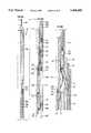
- FIG. 7Ashows a main well 1 into which a casing string 4, at least a portion of which comprises a lateral opening 21, has been lowered.
- the completion stage of well 1is generally similar to the conventional process of casing of a well.
- the casing string 4preferably, includes pipe elements called “casing” or “tubing” according to the denomination standardized by the "American Petroleum Institute". These pipes are connected to one another through threads.
- the string portion comprising opening 21is preferably made from one length of pipe so as to obtain the tubular element 24 shown in FIGS. 4A, 4B and 4C or 15A and 15C.
- tubular element or tubular elements 24As casing string 4 is being lowered, the operators integrate into the casing string the tubular element or tubular elements 24 so that, at the end of the lowering operation, these tubular elements 24 are positioned at the level of the point where the lateral drillings are to be started.
- connection 25for Connecting tubular element 24 may comprise a specific means for setting the orientation of the tubular element 24 with respect to the lower casing string. Any means known in general mechanics may be used, for example, the screw-nut principle with a jam nut. This principle may be transposed in the present case as follows: connection 25 includes a straight pin thread; the pipe on which connection 25 is threaded comprises a corresponding box thread; a ring acting as a jam nut is mounted on the pin thread.
- the attachment of the tubular element 24is achieved at the surface on the end of the string which is already assembled and introduced in the well.
- the direction of the opening of the elementis adjusted while mounting. This is achieved by knowing the orientation of the opening of the previous element already assembled in the main string through the setting in the string of a measuring tool at the level of this first opening.
- the measuring toolfor example, of the gyroscope type, is indexed with respect to the opening, for example, by the key 23.
- the position of the element 24is locked by threading the ring against the end shoulder of the box thread, at a tightening torque determined by the dimension of the thread.
- Other fastening systemsmay be conceived by the knowledge of the characteristics of the connections of the "casing" or "tubing" pipes.
- FIG. 14illustrates a simple connecting means between a tubular element 24 and a pipe of the casing string 4, a connection allowing element 24 to be adjusted and fixed in rotation.
- a casing collar 150comprises two different types of box threads, 151 and 153.
- Thread 151corresponds to the pin thread type of the pipes constituting the casing string 4.
- the connection through threads 151comprises a shoulder 152 on which the pin end of the casing string 4 is blocked under the action of a make-up torque.
- a distinctive feature of this connectionconventionally called a "premium connection" is that it allows no relative rotation of the pipes with respect to one another in case a twisting moment is applied to the whole of the string.
- connection comprising the thread 153has no shoulder, for example, of the LTC (Long Thread Collar) type according to the 5CT standards of the American Petroleum Institute.
- LTCLong Thread Collar
- the rotation of element 24 with respect to collar 150may be adjusted as a function of the make-up torque applied. Orientation being achieved, lateral locking screws 154 are blocked on the outside of the pin thread 25 of element 24.
- the casing string 4When the whole casing string 4 has been lowered into the main well, the casing string 4 is rotated around the axis thereof so as to orient all the openings 21 with respect to the producing formation.
- the rotating motionis achieved from the surface, either directly on the head of the string if the latter goes up to the surface, or on the maneuvering rods if the string is of the "liner" type, that is to say, if it stops at the level of the shoe of the previous cemented string.
- the main string and the openings thereofare properly positioned by controlling the orientation by a conventional measuring device adapted to the type of main well concerned.
- a lateral drilling stagewill be started after the guide means 10 shown in FIG. 7A have been installed.
- the guide means 10are assembled at the surface onto a running tool 56, for example, by way of fastening means 19 comprising notches (FIG. 5A) and slot 53, or by way of a releasing spear comprising an alignment sub 161, spear grapples 160 and a guide sub 162.
- the fasteningmay be achieved with any other equivalent means without departing from the scope of this invention.
- the meansare lowered into string 4 by maneuvering rods 57. Maneuvering rods must be understood as all the elements that could make a string, for instances casing, tubing, coil tubing, pumping rods, drillpipe.
- the depth reached by the meansis controlled by adding the lengths of rods 57.
- point 58guides the guide means 10, either into the anchoring position when the key enters groove 37 (FIG. 3B), or into the displacement position when the key 23 enters the groove 51 (FIG. 3C).
- the running tool 56is disconnected through a controlled action from the surface.
- a controlled actionThere are well-known systems which may be disconnected, for example, by rotation, mechanical jarring or by hydraulic control.
- the drilling operationmay then be achieved as schematically shown in FIG. 7B.
- rods 57must be added so as to reach another opening located deeper, in the direction of the bottom of the main well.
- FIG. 7Bshows a drill bit 59 during the drilling of the lateral well 2.
- the deviation angle I 1 between the main well and the beginning of the lateral wellis substantial equal to the angle I 2 formed by the tangent at the surface of the ramp 15, at the lower end thereof.
- the surface of the ramp 15may be planar, as shown in FIG. 2A, but preferably it will be curved so as to allow a reduction in the length of the opening 21.
- the temperature curvature of the ramp 15may also have a variable angle increasing in the direction of the opening 21.
- the allowable curvature of the ramp 15is limited by the stiffness of the drill string and by that of the lateral string.
- FIG. 7Crelates to the introduction of the lateral casing string 3 into the lateral well 2, and illustrates the equipments being lowered, before the connecting sub 7 is set definitively at the level of the opening 21.
- the liner type stringis ended by the connecting sub 7.
- the connecting sub 7is linked to the pipes of the casing string 3 by a joint 8.
- the casing 3is shown as being introduced into the lateral well 2, but the joint 8 and the connecting sub 7 are still located in the inner space of the main string 4 (FIG. 7C).
- the whole stringis lowered by the maneuvering rods 60 going up to the surface.
- a running tool 61is threadably attached substantially at the lower ends of the maneuvering rods 60.
- the casing string 3is hung on the running tool 61 through the fastening means 62.
- the running tool 61is preferably adapted for achieving at least one of holding the load represented by the weight of the casing string 3; withstanding a downward thrust on the casing string 3, a thrust that is generally exerted by drill collars or heavy weight drill pipes threaded above the tool 61; controlling the anchoring thereof on a lateral string from the surface; orienting the connecting sub 7 close to the slide so as to allow the positioning thereof with respect to the opening 21, with the orienting means cooperating with the upper part 20 of the guide means 10; displacing in translation the connecting sub 7 on the ramp 15 while keeping the desired orientation; and operating the gate 12 in the closing direction around the connecting sub 7 once the connecting sub is linked to the main string 4.
- the running toolmay comprise anchoring means 62 on the inside of the pipes of string 3, an orientation and displacement assembly 63, an assembly 64 for operating gate 12 comprising a finger 65 adapted for co-operating with the slot 66 of the body of the tubular element 24 (FIG. 4B) so as to be positioned above the gate.
- Finger 65is adapted for being displaced in translation so as to cause the gate 12 to slide in the housing thereof and to close the space between the opening and the connecting sub.
- the finger 65may be actuated radially and longitudinally through a means comprised of a screw, driven into rotation through the rotation at the surface of the maneuvering rods 60, or by displacing a hydraulic jack subjected to a fluid under pressure injected from the surface.
- a running tool designed from other mechanical systemsmay be used without departing from the scope of this invention, insofar as the purpose of the main functions, described above, is notably to implement the present system or method.
- FIG. 9Ashows a tool 61 for lowering and setting the lateral casing string 3.
- the toolis anchored in the connecting sub 7, which is integral with the casing string 3 by a swivel joint 131.
- the toolcomprises an assembly 64 for operating gate 12, which is not shown in FIG. 9A but which is detailed in FIGS. 10A, 10B and 10C, an assembly 63 for orienting and positioning the connecting sub 7 in the opening 21, an assembly 62 for anchoring the running tool 61 in the connecting sub 7.
- the anchoring assemblycomprises a locking means 87 integral with the end of a maneuvering pipe 88 and a part 86 holding the connecting sub 7. Holding part 86 has a face 130 complementary with respect to the section 13 of connecting sub 7.
- Part 86integral with pipe 88, fixes the connecting sub 7 in rotation with respect to pipe 88 when the section 13 of the connecting sub 7 is in contact with the face 130 of the holding part.
- the part of the pipe 88 located inside the connecting sub 7may comprise longitudinal grooves in which transverse pins integral with the wall of the connecting sub 7 are entrapped.
- the centering device including of the parts 146 and 147 of FIG. 6Fis not shown in this figure for reasons of clarity.
- FIG. 9Billustrates an anchoring system 87.
- the connecting sub 7comprises a circular groove 89 in the inner passageway thereof.
- a cylindrical part 90is integral with the end of pipe 88 through a thread 92.
- Part 90has several slots 93 distributed on the periphery, allowing a radial expansion of the end 91 of slotted part 90. This end is machined in a male shape, complementary with respect to groove 89.
- a stopper 94widens the end 91 of slotted part 90, thereby locking pipe 88 in the connecting sub 7.
- Stopper 94is integral with a piston 95 located in the bore of pipe 88.
- Seal means 96isolate the inner space of pipe 88 from the annular space.
- a shear pin 97makes piston 95 integral with pipe 88.
- orienting assembly 63comprises a jacket 98 integral with pipe 88 through a shear pin 99.
- the jacketcomprises a shape 100 complementary with respect to the shape of the orienting means 20 of the upper end of the guide means 10 (FIG. 2B).
- FIG. 9Athe outline of the upper part 18 of the guide means 10 is shown in dotted line in FIG. 9A.
- a key 101, integral with pipe 88,is located in a slot 102 provided in jacket 98.
- the shape 100 of the jacket of the running toolco-operates with the orienting means 20 of the guide means 10.
- Co-operationdirects the running tool and the connecting sub 7 into a determined direction, which is given by the orientation of the guide means 10 in conduit the casing string 4.
- the downward displacement of the running tool and of the casing string 3is blocked by part 18.
- Slot 102is located opposite the slot 53 of the upper part 18 of the guide means 10.
- the operatorapplies a shear force onto pin 99 through the action of stems or of drill collars.
- the breaking of the pinreleases pipe 88 from the jacket 98 and, in the same motion, the casing string moves downwards in a translation movement. In this movement, key 101 enters the slot 53.
- the connecting sub 7is correctly positioned in the opening 21.
- the assembly for maneuvering the gate 12is in the operation position.
- FIGS. 10A and 10Bshow an embodiment of an assembly 64 for operating the gate 12.
- FIG. 10Cshows said assembly in action.
- the two ends 103 and 104 of the assembly 64are respectively connected to the orienting assembly 63 and to the maneuvering string, which may comprise drill collars, heavy rods or rods.
- the outer body 105 of assembly 64comprises a window 106 of elongate shape along a generatrix of body 105, an upper guide bearing 107 and a lower guide bearing 108.
- a longitudinally mobile assembly 109coaxial to said outer body 105, comprises an upper piston 110, a lower piston 111, integral with a support 112 of a finger 76 for operating gate 12.
- Seal means 113 and 114are located respectively in the guide bearings 107 and 108 of assembly 109 in the outer body 105.
- the shoulders 117 and 116 of the outer body 105limit the displacement in translation of assembly 109 through the respective co-operation thereof with the shoulders 118 and 115 integral with support 112.
- a return spring 119holds assembly 109 in an upper position with respect to the outer body 105 or open position. In this open position, shoulders 118 and 117 are in contact, as shown in FIGS. 10A and 10B.
- the outside diameter of the upper piston 110, or the inner diameter of seal means 113is substantially larger than the outside diameter of the lower piston 111, or than the inner diameter of seal means 114. Assembly 109 therefore constitutes a differential piston.
- Finger 76is articulated around the pin 120.
- a leaf spring 131(FIG. 10C) is held on body 112 by a part 122 bearing pin 120.
- the spring arranged below finger 76tends to pivot the latter towards the outside of support 112.
- the finger 76In the position called open position, shown in FIGS. 10A and 10B, the finger 76 is held retracted, parallel to the axis of tool 64, by the part 121 of the outer body 105.
- a tubular rod 123is located inside the lower piston 111.
- Rod 123comprises, at the lower end thereof, a shoulder 132 adapted to co-operate with a dog (not shown) located at a determined distance in the end pipe 103, and at the upper end thereof, a pack-off nipple 124.
- a return spring 126holds rod 123 onto the shoulder 127 of lower piston 111.
- Pack-off nipple 124comprises seal means 128 and 129 on either side of at least one port 125 pierced in the support 112.
- the thrust forceis about 4300 lbs, that is 19,126 Newton.
- the forcecompresses spring 119 while lowering assembly 109.
- finger 76is radially expanded by its spring 131 (FIG. 10C).
- the finger 76passes through window 106, window 66 and the end of the finger co-operates with one of the openings 75 of gate 12.
- the thrust forcedisplaces the gate 12 which is therefore carried along by assembly 109 until dog 115 comes close to dog 116.
- the dog 132 of rod 123co-operates with a dog (not shown) which displaces, at the end of the displacement of assembly 109, pack-off nipple 124.
- port 125is released and communicates the inner space of pipes 88 with the annular space of the well, causing thereby a pressure drop inside these pipes 88.
- the operatoris informed of the end of a displacement.
- the operatorcan decrease the inner pressure so as to bring assembly 109 back to its open position under the action of return spring 119.
- the shape of finger 76 and of opening 75is such that this finger 76 is automatically released from this opening 75.
- the operatorrepeats the operation to make the gate move forward by successive strokes, until it is completely closed.
- a certain number of bores 75is necessary for this displacement by successive strokes. After a pressure buildup in the pipes, when the operator notices no pressure drop caused by the end of stroke signal constituted by nipple 124 and rod 123, the operator may deduce that the gate 12 is completely closed. This may be confirmed by the number of closing cycles that have already been achieved.
- an emergency jointcould be made up between the anchoring system 87 and pipe 88. This emergency joint is adapted to release pipe 88 from the occasionally stucked anchoring system 87, by mechanical actuation as torque, weight or tension, or by explosion as backoff operation.
- FIG. 13is a particularly advantageous variant of the intermediate joint 8 between the pipes of the lateral casing string 3 and the connecting sub 7. It comprises two tubular parts 171 and 172 connected to each other by a ball joint 170.
- Part 171has a certain length (about 1 meter) and a cross-section so as to exhibit a relative flexibility.
- Part 171could advantageously be in form of a bellow or a corrugated tube which exhibits a good flexibility even with a short length.
- One end 173has a substantially spherical shape, the other end 174 is integral with the connecting sub 7.
- End 173is held in a tubular part 175, integral with one end of part 172 and whose inner shape co-operates with the spherical shape 173 so as to constitute a ball joint 170.
- the other end of part 172is connected to the pipes of the lateral string 3.
- a flexible swivel jointallowing axial rotation and longitudinal disalignment of the connecting sub with respect to the lateral string 3 is thus constituted.
- part 172comprises in its inner wall the shape 89 (FIG. 9B) suited for cooperating with the anchoring device 87 fastened to the end of pipe 88 located in the inner space of the various tubular parts.
- FIGS. 11A, 11B and 11Cdetail an example of closing of the opening 21 of tubular element 24 during the casing operation of the main well and before drilling the lateral wells from the opening 21.
- Bands 180are wound around the tubular element 24 over the total length of the cap 16 by seeing to it that the coveting of the ends of the cap 16 is performed according to the detail illustrated in FIG. 11C.
- the spaces 181are filled with a filler before winding.
- a plate 182 made of a drillable materialmay seal the opening 27 (FIG. 15B) before it is covered with bands.
- the bandsmay be made from a fiber-reinforced composite material.
- FIGS. 16A and 16Billustrate a variant of the means for closing the space contained between the connecting sub 7 and the periphery of the opening 21.
- the principle hereis to equip element 24 with closing means in several parts 191 and 190.
- One part 190slides parallel to the longitudinal axis of element 24, and two parts 191 move in rotation around this same axis.
- FIGS. 16A and 16Bonly show the working principle since the embodiment of these means is understandable to the skilled artisan, in view of the present invention.
- Reference 193relates to the opening 27 of cap 16 in top view according to FIGS. 15A or 4A.
- Reference 192represents the section of the connecting sub 7 substantially in the plane of opening 27.
- the openinghas maximum dimensions.
- Lateral gates 191are separated from each other by a distance corresponding to the width of opening 21.
- a longitudinal-displacement gate 190comprises a V-shaped end 194 whose slope corresponds to the shape 195 of the lateral gates. Gates 190 and 191 are held in a housing including the body of the tubular element 24 and the cap 16. Once the lateral casing string 3 and its connecting sub 7 are set in the lateral borehole, the gate 190 is made to perform a translation to the right of FIG. 16B.
- FIG. 16Ashows gates 190 and 191 sealing the space between the connecting sub 7 and the opening 21, after their displacements.
- other equivalent mechanical systemsmay be used to move closing elements in a given direction from a fast translation displacement.
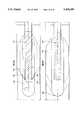
- FIGS. 8A and 8Bgive an example of applications of the method and the system according to the invention.
- a main well 69is drilled from the surface down to a geological zone 71, preferably a petroleum reservoir.
- the main well 69extends in the producing formation 71 through a substantially horizontal part 74. Achievement of the main well is gained according to well-known techniques.
- Part 74at least is cased according to the method of the invention.
- the casingperforated or not, comprises at least one portion comprised of at least one lateral opening from which lateral drains 72 are drilled.
- the lateral drainsmay be substantially horizontal in the oil-bearing stratum 71, upward or downward.
- the lay-out of the drainage wells 72depends on the oil-bearing stratum.
- the relative orientation of the openingsallows the drains to be achieved in the desired directions.
- the main well 69is substantially vertical down to the producing zone 71.
- the lateral wells 72are inclined, preferably substantially horizontal in the oil-bearing stratum.
- the tubular portion 73 of the casing of main well 69comprises at least one opening from which the lateral drain 72 is drilled.
- several openings located close to portion 73allow several drains 72 to be drilled.
- the openingswill be preferably located at different levels, for example for reasons of mechanical strength of the main casing or to simplify the setting of the various means used according to the system and the method of the present invention. It is possible for portion 73 not to be located in the producing formation.
- main well 69may comprise several portions 73 allowing the field to be drained at levels of different depths.
- the inventionmay also apply to the drainage of several separate oil-beating strata crossed through by main well 69.
- the casing of the main wellcomprises several portions 73 and drains 72, for example, one assembly per stratum.
- FIG. 8Bmain well 69 is shown crossing totally oil-bearing stratum 71. This lay-out is not at all limitative of the scope of the invention.
Landscapes
- Life Sciences & Earth Sciences (AREA)
- Engineering & Computer Science (AREA)
- Geology (AREA)
- Mining & Mineral Resources (AREA)
- Physics & Mathematics (AREA)
- Environmental & Geological Engineering (AREA)
- Fluid Mechanics (AREA)
- General Life Sciences & Earth Sciences (AREA)
- Geochemistry & Mineralogy (AREA)
- Earth Drilling (AREA)
Abstract
Description
Claims (61)
Applications Claiming Priority (4)
| Application Number | Priority Date | Filing Date | Title |
|---|---|---|---|
| FR9207142AFR2692316B1 (en) | 1992-06-12 | 1992-06-12 | SYSTEM AND METHOD FOR LATERAL DRILLING AND EQUIPMENT, APPLICATION TO OIL OIL EXPLOITATION. |
| FR9207142 | 1992-06-12 | ||
| FR9300154 | 1993-01-08 | ||
| FR939300154AFR2692315B1 (en) | 1992-06-12 | 1993-01-08 | System and method for drilling and equipping a lateral well, application to the exploitation of oil fields. |
Publications (1)
| Publication Number | Publication Date |
|---|---|
| US5458209Atrue US5458209A (en) | 1995-10-17 |
Family
ID=26229518
Family Applications (1)
| Application Number | Title | Priority Date | Filing Date |
|---|---|---|---|
| US08/074,475Expired - LifetimeUS5458209A (en) | 1992-06-12 | 1993-06-11 | Device, system and method for drilling and completing a lateral well |
Country Status (10)
| Country | Link |
|---|---|
| US (1) | US5458209A (en) |
| EP (1) | EP0574326B1 (en) |
| CN (3) | CN1035784C (en) |
| AU (1) | AU663951B2 (en) |
| CA (1) | CA2098272C (en) |
| DK (1) | DK0574326T3 (en) |
| FR (1) | FR2692315B1 (en) |
| MY (1) | MY110459A (en) |
| NO (1) | NO306266B1 (en) |
| RU (1) | RU2103472C1 (en) |
Cited By (181)
| Publication number | Priority date | Publication date | Assignee | Title |
|---|---|---|---|---|
| GB2297776A (en)* | 1995-01-12 | 1996-08-14 | Baker Hughes Inc | Whipstock assembly for a sleeved casing |
| US5615740A (en)* | 1995-06-29 | 1997-04-01 | Baroid Technology, Inc. | Internal pressure sleeve for use with easily drillable exit ports |
| WO1998005845A1 (en)* | 1996-08-08 | 1998-02-12 | Baker Hughes Incorporated | Method for forming a casing window |
| WO1998009047A1 (en)* | 1996-08-30 | 1998-03-05 | Baker Hughes Incorporated | Coiled tubing entry guide |
| WO1998009048A1 (en) | 1996-08-29 | 1998-03-05 | Baker Hughes Incorporated | Re-entry tool for use in a multilateral well |
| US5730221A (en) | 1996-07-15 | 1998-03-24 | Halliburton Energy Services, Inc | Methods of completing a subterranean well |
| US5785133A (en)* | 1995-08-29 | 1998-07-28 | Tiw Corporation | Multiple lateral hydrocarbon recovery system and method |
| US5803176A (en) | 1996-01-24 | 1998-09-08 | Weatherford/Lamb, Inc. | Sidetracking operations |
| US5813465A (en) | 1996-07-15 | 1998-09-29 | Halliburton Energy Services, Inc. | Apparatus for completing a subterranean well and associated methods of using same |
| US5826651A (en) | 1993-09-10 | 1998-10-27 | Weatherford/Lamb, Inc. | Wellbore single trip milling |
| US5833003A (en) | 1996-07-15 | 1998-11-10 | Halliburton Energy Services, Inc. | Apparatus for completing a subterranean well and associated methods of using same |
| US5836387A (en) | 1993-09-10 | 1998-11-17 | Weatherford/Lamb, Inc. | System for securing an item in a tubular channel in a wellbore |
| US5862862A (en) | 1996-07-15 | 1999-01-26 | Halliburton Energy Services, Inc. | Apparatus for completing a subterranean well and associated methods of using same |
| US5887668A (en)* | 1993-09-10 | 1999-03-30 | Weatherford/Lamb, Inc. | Wellbore milling-- drilling |
| US5887655A (en)* | 1993-09-10 | 1999-03-30 | Weatherford/Lamb, Inc | Wellbore milling and drilling |
| US5915474A (en)* | 1995-02-03 | 1999-06-29 | Integrated Drilling Services Limited | Multiple drain drilling and production apparatus |
| EP0825327A3 (en)* | 1996-07-15 | 1999-08-18 | Halliburton Energy Services, Inc. | Apparatus for completing a subterranean well and method of using same |
| US5941308A (en)* | 1996-01-26 | 1999-08-24 | Schlumberger Technology Corporation | Flow segregator for multi-drain well completion |
| US5944101A (en)* | 1998-06-15 | 1999-08-31 | Atlantic Richfield Company | Apparatus for milling a window in well tubular |
| US5944107A (en)* | 1996-03-11 | 1999-08-31 | Schlumberger Technology Corporation | Method and apparatus for establishing branch wells at a node of a parent well |
| WO1999039073A3 (en)* | 1998-01-30 | 1999-11-04 | Dresser Ind | Method and apparatus for running two tubing strings into a well |
| US5979560A (en)* | 1997-09-09 | 1999-11-09 | Nobileau; Philippe | Lateral branch junction for well casing |
| EP0819828A3 (en)* | 1996-07-15 | 1999-11-17 | Halliburton Energy Services, Inc. | Apparatus for completing a subterranean well and method of using same |
| EP0819825A3 (en)* | 1996-07-15 | 1999-11-17 | Halliburton Energy Services, Inc. | Apparatus for completing a subterranean well and method of using same |
| EP0819823A3 (en)* | 1996-07-15 | 1999-11-17 | Halliburton Energy Services, Inc. | Apparatus for completing a subterranean well and method of using same |
| US6003601A (en)* | 1997-02-13 | 1999-12-21 | Halliburton Energy Services, Inc. | Methods of completing a subterranean well and associated apparatus |
| US6012516A (en)* | 1997-09-05 | 2000-01-11 | Schlumberger Technology Corporation | Deviated borehole drilling assembly |
| US6012527A (en)* | 1996-10-01 | 2000-01-11 | Schlumberger Technology Corporation | Method and apparatus for drilling and re-entering multiple lateral branched in a well |
| US6035935A (en)* | 1998-05-22 | 2000-03-14 | Halliburton Energy Services, Inc. | Method for establishing connectivity between lateral and parent wellbores |
| US6041855A (en)* | 1998-04-23 | 2000-03-28 | Halliburton Energy Services, Inc. | High torque pressure sleeve for easily drillable casing exit ports |
| US6056059A (en)* | 1996-03-11 | 2000-05-02 | Schlumberger Technology Corporation | Apparatus and method for establishing branch wells from a parent well |
| WO2000032902A1 (en)* | 1998-11-30 | 2000-06-08 | Brunet Charles G | Downhole apparatus and method for milling a window and at least one key-way in a well casing |
| US6123150A (en)* | 1995-07-17 | 2000-09-26 | Smith International | Branch boreholes |
| EP0945586A3 (en)* | 1998-03-24 | 2000-10-11 | Halliburton Energy Services, Inc. | Method and apparatus for forming a wellbore junction |
| US6135206A (en) | 1996-07-15 | 2000-10-24 | Halliburton Energy Services, Inc. | Apparatus for completing a subterranean well and associated methods of using same |
| US6206111B1 (en) | 1999-06-23 | 2001-03-27 | Halliburton Energy Services, Inc. | High pressure internal sleeve for use with easily drillable exit ports |
| US6209648B1 (en) | 1998-11-19 | 2001-04-03 | Schlumberger Technology Corporation | Method and apparatus for connecting a lateral branch liner to a main well bore |
| WO2001025587A1 (en)* | 1999-09-28 | 2001-04-12 | Brunet Charles G | Assembly and method for locating lateral wellbores |
| US6244339B1 (en)* | 1997-06-14 | 2001-06-12 | Weatherford/Lamb, Inc. | Apparatus for and a method of drilling a lateral borehole |
| US6253852B1 (en) | 1997-09-09 | 2001-07-03 | Philippe Nobileau | Lateral branch junction for well casing |
| US6279659B1 (en) | 1998-10-20 | 2001-08-28 | Weatherford Lamb, Inc. | Assembly and method for providing a means of support and positioning for drilling multi-lateral wells and for reentry therein through a premilled window |
| US6283216B1 (en) | 1996-03-11 | 2001-09-04 | Schlumberger Technology Corporation | Apparatus and method for establishing branch wells from a parent well |
| US6308782B1 (en)* | 1998-01-30 | 2001-10-30 | Halliburton Energy Services, Inc | Method and apparatus for one-trip insertion and retrieval of a tool and auxiliary device |
| US6332498B1 (en) | 1997-09-05 | 2001-12-25 | Schlumberger Technology Corp. | Deviated borehole drilling assembly |
| GB2373274A (en)* | 1998-01-30 | 2002-09-18 | Dresser Ind | Soft release coupling of use with two tubing strings |
| US6530439B2 (en) | 2000-04-06 | 2003-03-11 | Henry B. Mazorow | Flexible hose with thrusters for horizontal well drilling |
| US20030075334A1 (en)* | 1996-05-02 | 2003-04-24 | Weatherford Lamb, Inc. | Wellbore liner system |
| US6561288B2 (en) | 1998-11-20 | 2003-05-13 | Cdx Gas, Llc | Method and system for accessing subterranean deposits from the surface |
| US6575235B2 (en) | 1998-11-20 | 2003-06-10 | Cdx Gas, Llc | Subterranean drainage pattern |
| US6578636B2 (en) | 2000-02-16 | 2003-06-17 | Performance Research & Drilling, Llc | Horizontal directional drilling in wells |
| US6598686B1 (en) | 1998-11-20 | 2003-07-29 | Cdx Gas, Llc | Method and system for enhanced access to a subterranean zone |
| EP1296018A3 (en)* | 1998-04-01 | 2003-11-05 | Weatherford/Lamb, Inc. | Lining a lateral wellbore |
| US6662870B1 (en) | 2001-01-30 | 2003-12-16 | Cdx Gas, L.L.C. | Method and system for accessing subterranean deposits from a limited surface area |
| WO2003106806A1 (en)* | 2002-06-14 | 2003-12-24 | Panjin Www Developing Science And Technology Company Limited | A device and a method for drilling and completing a horizontal wellbore |
| US6679322B1 (en) | 1998-11-20 | 2004-01-20 | Cdx Gas, Llc | Method and system for accessing subterranean deposits from the surface |
| US6681855B2 (en) | 2001-10-19 | 2004-01-27 | Cdx Gas, L.L.C. | Method and system for management of by-products from subterranean zones |
| US20040016547A1 (en)* | 2002-07-26 | 2004-01-29 | Brunet Charles G. | Apparatus and method to complete a multilateral junction |
| US6708769B2 (en)* | 2000-05-05 | 2004-03-23 | Weatherford/Lamb, Inc. | Apparatus and methods for forming a lateral wellbore |
| US6708764B2 (en) | 2002-07-12 | 2004-03-23 | Cdx Gas, L.L.C. | Undulating well bore |
| US6725927B2 (en) | 2002-02-25 | 2004-04-27 | Schlumberger Technology Corporation | Method and system for avoiding damage to behind-casing structures |
| US6725922B2 (en) | 2002-07-12 | 2004-04-27 | Cdx Gas, Llc | Ramping well bores |
| US6732802B2 (en) | 2002-03-21 | 2004-05-11 | Halliburton Energy Services, Inc. | Isolation bypass joint system and completion method for a multilateral well |
| US6749026B2 (en) | 2002-03-21 | 2004-06-15 | Halliburton Energy Services, Inc. | Method of forming downhole tubular string connections |
| WO2004051053A1 (en)* | 2002-12-02 | 2004-06-17 | Smith International, Inc. | Apparatus and method for opening and closing lateral boreholes |
| US20040129414A1 (en)* | 2001-04-23 | 2004-07-08 | Kriesels Petrus Cornelis | Method of drilling an ultra-short radius borehole |
| US6761217B1 (en)* | 1999-09-16 | 2004-07-13 | Smith International, Inc. | Downhole latch assembly and method of using the same |
| US20040159429A1 (en)* | 2003-02-14 | 2004-08-19 | Brockman Mark W. | Testing a junction of plural bores in a well |
| US20040168808A1 (en)* | 2002-03-21 | 2004-09-02 | Smith Ray C. | Monobore wellbore and method for completing same |
| US20040168809A1 (en)* | 1997-09-09 | 2004-09-02 | Nobileau Philippe C. | Apparatus and method for installing a branch junction from a main well |
| US6830106B2 (en) | 2002-08-22 | 2004-12-14 | Halliburton Energy Services, Inc. | Multilateral well completion apparatus and methods of use |
| US6848508B2 (en) | 2001-10-30 | 2005-02-01 | Cdx Gas, Llc | Slant entry well system and method |
| US6857487B2 (en) | 2002-12-30 | 2005-02-22 | Weatherford/Lamb, Inc. | Drilling with concentric strings of casing |
| US6883611B2 (en) | 2002-04-12 | 2005-04-26 | Halliburton Energy Services, Inc. | Sealed multilateral junction system |
| US6896075B2 (en) | 2002-10-11 | 2005-05-24 | Weatherford/Lamb, Inc. | Apparatus and methods for drilling with casing |
| US6899186B2 (en) | 2002-12-13 | 2005-05-31 | Weatherford/Lamb, Inc. | Apparatus and method of drilling with casing |
| US20050167109A1 (en)* | 2004-01-29 | 2005-08-04 | Neil Hepburn | Sealed branch wellbore transition joint |
| US6942030B2 (en) | 2002-09-12 | 2005-09-13 | Cdx Gas, Llc | Three-dimensional well system for accessing subterranean zones |
| US6953096B2 (en) | 2002-12-31 | 2005-10-11 | Weatherford/Lamb, Inc. | Expandable bit with secondary release device |
| US20050241831A1 (en)* | 2004-05-03 | 2005-11-03 | Steele David J | Anchor for branch wellbore liner |
| US20050247451A1 (en)* | 2004-05-06 | 2005-11-10 | Horizon Expansion Tech, Llc | Method and apparatus for completing lateral channels from an existing oil or gas well |
| US6964308B1 (en) | 2002-10-08 | 2005-11-15 | Cdx Gas, Llc | Method of drilling lateral wellbores from a slant well without utilizing a whipstock |
| US6988548B2 (en) | 2002-10-03 | 2006-01-24 | Cdx Gas, Llc | Method and system for removing fluid from a subterranean zone using an enlarged cavity |
| US6991047B2 (en) | 2002-07-12 | 2006-01-31 | Cdx Gas, Llc | Wellbore sealing system and method |
| US6991048B2 (en) | 2002-07-12 | 2006-01-31 | Cdx Gas, Llc | Wellbore plug system and method |
| US6994176B2 (en) | 2002-07-29 | 2006-02-07 | Weatherford/Lamb, Inc. | Adjustable rotating guides for spider or elevator |
| US7004264B2 (en) | 2002-03-16 | 2006-02-28 | Weatherford/Lamb, Inc. | Bore lining and drilling |
| US7013997B2 (en) | 1994-10-14 | 2006-03-21 | Weatherford/Lamb, Inc. | Methods and apparatus for cementing drill strings in place for one pass drilling and completion of oil and gas wells |
| US7025154B2 (en) | 1998-11-20 | 2006-04-11 | Cdx Gas, Llc | Method and system for circulating fluid in a well system |
| US7036610B1 (en) | 1994-10-14 | 2006-05-02 | Weatherford / Lamb, Inc. | Apparatus and method for completing oil and gas wells |
| US7040420B2 (en) | 1994-10-14 | 2006-05-09 | Weatherford/Lamb, Inc. | Methods and apparatus for cementing drill strings in place for one pass drilling and completion of oil and gas wells |
| US7048050B2 (en) | 1994-10-14 | 2006-05-23 | Weatherford/Lamb, Inc. | Method and apparatus for cementing drill strings in place for one pass drilling and completion of oil and gas wells |
| US20060137874A1 (en)* | 2004-12-28 | 2006-06-29 | Schlumberger Technology Corporation | System and Technique for Orienting and Positioning a Lateral String in a Multilateral System |
| US7073598B2 (en) | 2001-05-17 | 2006-07-11 | Weatherford/Lamb, Inc. | Apparatus and methods for tubular makeup interlock |
| US7073595B2 (en) | 2002-09-12 | 2006-07-11 | Cdx Gas, Llc | Method and system for controlling pressure in a dual well system |
| US7090021B2 (en) | 1998-08-24 | 2006-08-15 | Bernd-Georg Pietras | Apparatus for connecting tublars using a top drive |
| US7093675B2 (en) | 2000-08-01 | 2006-08-22 | Weatherford/Lamb, Inc. | Drilling method |
| US7096982B2 (en) | 2003-02-27 | 2006-08-29 | Weatherford/Lamb, Inc. | Drill shoe |
| US7100687B2 (en) | 2003-11-17 | 2006-09-05 | Cdx Gas, Llc | Multi-purpose well bores and method for accessing a subterranean zone from the surface |
| US7100710B2 (en) | 1994-10-14 | 2006-09-05 | Weatherford/Lamb, Inc. | Methods and apparatus for cementing drill strings in place for one pass drilling and completion of oil and gas wells |
| US7100713B2 (en) | 2000-04-28 | 2006-09-05 | Weatherford/Lamb, Inc. | Expandable apparatus for drift and reaming borehole |
| US7108084B2 (en) | 1994-10-14 | 2006-09-19 | Weatherford/Lamb, Inc. | Methods and apparatus for cementing drill strings in place for one pass drilling and completion of oil and gas wells |
| US7117957B2 (en) | 1998-12-22 | 2006-10-10 | Weatherford/Lamb, Inc. | Methods for drilling and lining a wellbore |
| US7128154B2 (en) | 2003-01-30 | 2006-10-31 | Weatherford/Lamb, Inc. | Single-direction cementing plug |
| US7128161B2 (en) | 1998-12-24 | 2006-10-31 | Weatherford/Lamb, Inc. | Apparatus and methods for facilitating the connection of tubulars using a top drive |
| US7134494B2 (en) | 2003-06-05 | 2006-11-14 | Cdx Gas, Llc | Method and system for recirculating fluid in a well system |
| US7137454B2 (en) | 1998-07-22 | 2006-11-21 | Weatherford/Lamb, Inc. | Apparatus for facilitating the connection of tubulars using a top drive |
| US7140445B2 (en) | 1997-09-02 | 2006-11-28 | Weatherford/Lamb, Inc. | Method and apparatus for drilling with casing |
| US20060266531A1 (en)* | 2004-01-29 | 2006-11-30 | Neil Hepburn | Sealed branch wellbore transition joint |
| US7147068B2 (en) | 1994-10-14 | 2006-12-12 | Weatherford / Lamb, Inc. | Methods and apparatus for cementing drill strings in place for one pass drilling and completion of oil and gas wells |
| US20060278393A1 (en)* | 2004-05-06 | 2006-12-14 | Horizontal Expansion Tech, Llc | Method and apparatus for completing lateral channels from an existing oil or gas well |
| US7163063B2 (en) | 2003-11-26 | 2007-01-16 | Cdx Gas, Llc | Method and system for extraction of resources from a subterranean well bore |
| US20070034384A1 (en)* | 2005-07-08 | 2007-02-15 | Pratt Christopher A | Whipstock liner |
| US7188687B2 (en) | 1998-12-22 | 2007-03-13 | Weatherford/Lamb, Inc. | Downhole filter |
| US7191840B2 (en) | 2003-03-05 | 2007-03-20 | Weatherford/Lamb, Inc. | Casing running and drilling system |
| US7207390B1 (en) | 2004-02-05 | 2007-04-24 | Cdx Gas, Llc | Method and system for lining multilateral wells |
| US7207395B2 (en) | 2004-01-30 | 2007-04-24 | Cdx Gas, Llc | Method and system for testing a partially formed hydrocarbon well for evaluation and well planning refinement |
| US7213656B2 (en) | 1998-12-24 | 2007-05-08 | Weatherford/Lamb, Inc. | Apparatus and method for facilitating the connection of tubulars using a top drive |
| US7216727B2 (en) | 1999-12-22 | 2007-05-15 | Weatherford/Lamb, Inc. | Drilling bit for drilling while running casing |
| US7219744B2 (en) | 1998-08-24 | 2007-05-22 | Weatherford/Lamb, Inc. | Method and apparatus for connecting tubulars using a top drive |
| US7222670B2 (en) | 2004-02-27 | 2007-05-29 | Cdx Gas, Llc | System and method for multiple wells from a common surface location |
| US7228901B2 (en) | 1994-10-14 | 2007-06-12 | Weatherford/Lamb, Inc. | Method and apparatus for cementing drill strings in place for one pass drilling and completion of oil and gas wells |
| US7264048B2 (en) | 2003-04-21 | 2007-09-04 | Cdx Gas, Llc | Slot cavity |
| US7264067B2 (en) | 2003-10-03 | 2007-09-04 | Weatherford/Lamb, Inc. | Method of drilling and completing multiple wellbores inside a single caisson |
| US7284617B2 (en) | 2004-05-20 | 2007-10-23 | Weatherford/Lamb, Inc. | Casing running head |
| US7299864B2 (en) | 2004-12-22 | 2007-11-27 | Cdx Gas, Llc | Adjustable window liner |
| US7303022B2 (en) | 2002-10-11 | 2007-12-04 | Weatherford/Lamb, Inc. | Wired casing |
| US20070286685A1 (en)* | 2006-06-09 | 2007-12-13 | Precision Pier, Usa, Inc. | Soil Stabilization And Anchorage System |
| US7311148B2 (en) | 1999-02-25 | 2007-12-25 | Weatherford/Lamb, Inc. | Methods and apparatus for wellbore construction and completion |
| US7325610B2 (en) | 2000-04-17 | 2008-02-05 | Weatherford/Lamb, Inc. | Methods and apparatus for handling and drilling with tubulars or casing |
| US7334650B2 (en) | 2000-04-13 | 2008-02-26 | Weatherford/Lamb, Inc. | Apparatus and methods for drilling a wellbore using casing |
| US7353877B2 (en) | 2004-12-21 | 2008-04-08 | Cdx Gas, Llc | Accessing subterranean resources by formation collapse |
| US7360594B2 (en) | 2003-03-05 | 2008-04-22 | Weatherford/Lamb, Inc. | Drilling with casing latch |
| US7360595B2 (en) | 2002-05-08 | 2008-04-22 | Cdx Gas, Llc | Method and system for underground treatment of materials |
| US7370707B2 (en) | 2003-04-04 | 2008-05-13 | Weatherford/Lamb, Inc. | Method and apparatus for handling wellbore tubulars |
| US7373984B2 (en) | 2004-12-22 | 2008-05-20 | Cdx Gas, Llc | Lining well bore junctions |
| US7413020B2 (en) | 2003-03-05 | 2008-08-19 | Weatherford/Lamb, Inc. | Full bore lined wellbores |
| US7419223B2 (en) | 2003-11-26 | 2008-09-02 | Cdx Gas, Llc | System and method for enhancing permeability of a subterranean zone at a horizontal well bore |
| US7503397B2 (en) | 2004-07-30 | 2009-03-17 | Weatherford/Lamb, Inc. | Apparatus and methods of setting and retrieving casing with drilling latch and bottom hole assembly |
| US7509722B2 (en) | 1997-09-02 | 2009-03-31 | Weatherford/Lamb, Inc. | Positioning and spinning device |
| US7571771B2 (en) | 2005-05-31 | 2009-08-11 | Cdx Gas, Llc | Cavity well system |
| US7617866B2 (en) | 1998-08-24 | 2009-11-17 | Weatherford/Lamb, Inc. | Methods and apparatus for connecting tubulars using a top drive |
| RU2373367C1 (en)* | 2008-07-04 | 2009-11-20 | Открытое акционерное общество "Татнефть" им. В.Д. Шашина | Method for drilling of fan wells and device for drilling of fan wells |
| US7650944B1 (en) | 2003-07-11 | 2010-01-26 | Weatherford/Lamb, Inc. | Vessel for well intervention |
| US7712523B2 (en) | 2000-04-17 | 2010-05-11 | Weatherford/Lamb, Inc. | Top drive casing system |
| US7730965B2 (en) | 2002-12-13 | 2010-06-08 | Weatherford/Lamb, Inc. | Retractable joint and cementing shoe for use in completing a wellbore |
| US20100186953A1 (en)* | 2006-03-30 | 2010-07-29 | Schlumberger Technology Corporation | Measuring a characteristic of a well proximate a region to be gravel packed |
| US20100200291A1 (en)* | 2006-03-30 | 2010-08-12 | Schlumberger Technology Corporation | Completion system having a sand control assembly, an inductive coupler, and a sensor proximate to the sand control assembly |
| US20100218996A1 (en)* | 2009-02-27 | 2010-09-02 | Conocophillips Company | Directional sidetrack well drilling system |
| US20100252275A1 (en)* | 2009-04-02 | 2010-10-07 | Knight Information Systems, Llc | Lateral Well Locator and Reentry Apparatus and Method |
| US20100252257A1 (en)* | 2009-04-02 | 2010-10-07 | Cronley Gerald J | Multi-Window Lateral Well Locator/Reentry Apparatus and Method |
| US7857052B2 (en) | 2006-05-12 | 2010-12-28 | Weatherford/Lamb, Inc. | Stage cementing methods used in casing while drilling |
| US20110079400A1 (en)* | 2009-10-07 | 2011-04-07 | Schlumberger Technology Corporation | Active integrated completion installation system and method |
| US7938201B2 (en) | 2002-12-13 | 2011-05-10 | Weatherford/Lamb, Inc. | Deep water drilling with casing |
| US20110186291A1 (en)* | 2010-02-04 | 2011-08-04 | Loc Lang | Methods and systems for orienting in a bore |
| US20110192596A1 (en)* | 2010-02-07 | 2011-08-11 | Schlumberger Technology Corporation | Through tubing intelligent completion system and method with connection |
| CN102206991A (en)* | 2010-03-31 | 2011-10-05 | 哈利伯顿能源服务公司 | Well assembly with millable member in opening |
| USRE42877E1 (en) | 2003-02-07 | 2011-11-01 | Weatherford/Lamb, Inc. | Methods and apparatus for wellbore construction and completion |
| WO2011084566A3 (en)* | 2009-12-16 | 2012-01-26 | Tejas Completion Solutions, Llc | T-frac system run in system |
| US20120111636A1 (en)* | 2010-11-04 | 2012-05-10 | Halliburton Energy Services, Inc | Combination whipstock and completion deflector |
| US8186459B1 (en) | 2008-06-23 | 2012-05-29 | Horizontal Expansion Tech, Llc | Flexible hose with thrusters and shut-off valve for horizontal well drilling |
| US8235127B2 (en) | 2006-03-30 | 2012-08-07 | Schlumberger Technology Corporation | Communicating electrical energy with an electrical device in a well |
| US8276689B2 (en) | 2006-05-22 | 2012-10-02 | Weatherford/Lamb, Inc. | Methods and apparatus for drilling with casing |
| US8291974B2 (en) | 1998-11-20 | 2012-10-23 | Vitruvian Exploration, Llc | Method and system for accessing subterranean deposits from the surface and tools therefor |
| US8333245B2 (en) | 2002-09-17 | 2012-12-18 | Vitruvian Exploration, Llc | Accelerated production of gas from a subterranean zone |
| US8376052B2 (en) | 1998-11-20 | 2013-02-19 | Vitruvian Exploration, Llc | Method and system for surface production of gas from a subterranean zone |
| CN103119243A (en)* | 2010-07-28 | 2013-05-22 | 帕克斯普拉斯能源服务有限公司 | Wellbore lateral liner placement system |
| US8505621B2 (en) | 2010-03-30 | 2013-08-13 | Halliburton Energy Services, Inc. | Well assembly with recesses facilitating branch wellbore creation |
| US8789580B2 (en)* | 2012-04-30 | 2014-07-29 | Halliburton Energy Services, Inc. | Wellbore casing section with moveable portion for providing a casing exit |
| CN104314498A (en)* | 2014-08-18 | 2015-01-28 | 中国石油集团长城钻探工程有限公司 | Efficient well completion method for sidetrack horizontal well |
| US20150047165A1 (en)* | 2010-03-23 | 2015-02-19 | Baker Hughes Incorporated | Diverting system |
| US9175523B2 (en) | 2006-03-30 | 2015-11-03 | Schlumberger Technology Corporation | Aligning inductive couplers in a well |
| US9175560B2 (en) | 2012-01-26 | 2015-11-03 | Schlumberger Technology Corporation | Providing coupler portions along a structure |
| US9234613B2 (en) | 2010-05-28 | 2016-01-12 | Halliburton Energy Services, Inc. | Well assembly coupling |
| US9249559B2 (en) | 2011-10-04 | 2016-02-02 | Schlumberger Technology Corporation | Providing equipment in lateral branches of a well |
| US9371721B2 (en) | 2012-03-02 | 2016-06-21 | Halliburton Energy Services, Inc. | Subsurface well systems with multiple drain wells extending from production well and methods for use thereof |
| US9644476B2 (en) | 2012-01-23 | 2017-05-09 | Schlumberger Technology Corporation | Structures having cavities containing coupler portions |
| US9835011B2 (en) | 2013-01-08 | 2017-12-05 | Knight Information Systems, Llc | Multi-window lateral well locator/reentry apparatus and method |
| US9938823B2 (en) | 2012-02-15 | 2018-04-10 | Schlumberger Technology Corporation | Communicating power and data to a component in a well |
| US10036234B2 (en) | 2012-06-08 | 2018-07-31 | Schlumberger Technology Corporation | Lateral wellbore completion apparatus and method |
| US10774603B2 (en) | 2016-09-15 | 2020-09-15 | Halliburton Energy Services, Inc. | Hookless hanger for a multilateral wellbore |
| US11448041B2 (en)* | 2019-08-13 | 2022-09-20 | Halliburton Energy Services, Inc. | Drillable window assembly for controlling the geometry of a multilateral wellbore junction |
Families Citing this family (35)
| Publication number | Priority date | Publication date | Assignee | Title |
|---|---|---|---|---|
| US5454430A (en)* | 1992-08-07 | 1995-10-03 | Baker Hughes Incorporated | Scoophead/diverter assembly for completing lateral wellbores |
| US5427177A (en)* | 1993-06-10 | 1995-06-27 | Baker Hughes Incorporated | Multi-lateral selective re-entry tool |
| US5439051A (en)* | 1994-01-26 | 1995-08-08 | Baker Hughes Incorporated | Lateral connector receptacle |
| US5411082A (en)* | 1994-01-26 | 1995-05-02 | Baker Hughes Incorporated | Scoophead running tool |
| US5435392A (en)* | 1994-01-26 | 1995-07-25 | Baker Hughes Incorporated | Liner tie-back sleeve |
| US5566763A (en)* | 1994-08-26 | 1996-10-22 | Halliburton Company | Decentralizing, centralizing, locating and orienting subsystems and methods for subterranean multilateral well drilling and completion |
| US5564503A (en)* | 1994-08-26 | 1996-10-15 | Halliburton Company | Methods and systems for subterranean multilateral well drilling and completion |
| US5477925A (en)* | 1994-12-06 | 1995-12-26 | Baker Hughes Incorporated | Method for multi-lateral completion and cementing the juncture with lateral wellbores |
| NO311905B1 (en)* | 1996-08-13 | 2002-02-11 | Baker Hughes Inc | Feeding tube segment, as well as method for forming a window in a feeding tube segment |
| WO1998009054A1 (en) | 1996-08-30 | 1998-03-05 | Baker Hughes Incorporated | Cement reinforced inflatable seal for a junction of a multilateral |
| RU2147063C1 (en)* | 1998-04-22 | 2000-03-27 | Рахматуллин Альберт Худжатович | Method for creation of whipstock |
| RU2136835C1 (en)* | 1998-05-13 | 1999-09-10 | Тюменский научно-исследовательский и проектный институт природного газа и газовых технологий | Wedge-type whipstock |
| RU2149247C1 (en)* | 1999-08-04 | 2000-05-20 | Общество с ограниченной ответственностью "ИНТЕНСИФИКАЦИЯ" | Method for construction of multiple-hole well |
| RU2172384C2 (en)* | 1999-08-09 | 2001-08-20 | Открытое акционерное общество "Татнефть" Татарский научно-исследовательский и проектный институт нефти "ТатНИПИнефть" | Method of drilling of auxiliary wellbore from flow string |
| RU2208119C2 (en)* | 1999-09-20 | 2003-07-10 | Ухтинский государственный технический университет | Process of construction and running of multiple face hole |
| RU2213196C2 (en)* | 2000-01-17 | 2003-09-27 | Ухтинский государственный технический университет | Device for operation of multiple wells |
| RU2182637C1 (en)* | 2000-11-14 | 2002-05-20 | Дочернее общество с ограниченной ответственностью "Башнипинефть" ОАО "Акционерная нефтяная компания "Башнефть" | Process of drilling of additional shaft of well |
| RU2209917C1 (en)* | 2002-01-25 | 2003-08-10 | Григорьев Петр Михайлович | Way for oriented cutting of windows in casing string |
| NO336220B1 (en) | 2002-11-07 | 2015-06-22 | Weatherford Lamb | Device and method for completing wellbore connections. |
| RU2319826C2 (en)* | 2002-11-11 | 2008-03-20 | Бейкер Хьюз Инкорпорейтед | Method and device to create cemented system, which connects main and side well bores |
| RU2271430C2 (en)* | 2003-09-15 | 2006-03-10 | Общество с ограниченной ответственностью Когалымский научно-исследовательский и проектный институт нефти (ООО "КогалымНИПИнефть") | Pipe string coupling |
| RU2268982C1 (en)* | 2004-07-16 | 2006-01-27 | Открытое акционерное общество "Татнефть" им. В.Д. Шашина | Multilateral well building method |
| RU2265711C1 (en)* | 2004-07-16 | 2005-12-10 | Открытое акционерное общество "Татнефть" им. В.Д. Шашина | Cluster well construction method |
| RU2269632C1 (en)* | 2004-08-02 | 2006-02-10 | Открытое акционерное общество "Татнефть" им. В.Д. Шашина | Multilateral well building method |
| RU2269633C1 (en)* | 2004-08-19 | 2006-02-10 | Открытое акционерное общество "Татнефть" им. В.Д. Шашина | Multilateral well building method |
| RU2298629C1 (en)* | 2005-10-28 | 2007-05-10 | Открытое акционерное общество "Татнефть" им. В.Д. Шашина | Multibranch well drilling method |
| RU2441140C2 (en)* | 2009-11-30 | 2012-01-27 | Открытое акционерное общество "Акционерная нефтяная компания "Башнефть" (ОАО "АНК "Башнефть") | Device for hanger lowering and cementing of casing liner in well |
| CN102022083B (en)* | 2010-11-20 | 2013-02-13 | 中国石油集团西部钻探工程有限公司 | Rotary guide well drilling tool |
| US20120279709A1 (en)* | 2011-05-06 | 2012-11-08 | Smith International, Inc. | Expandable downhole casing coupling locator tool |
| US8701775B2 (en)* | 2011-06-03 | 2014-04-22 | Halliburton Energy Services, Inc. | Completion of lateral bore with high pressure multibore junction assembly |
| CN103541657A (en)* | 2012-07-09 | 2014-01-29 | 中国石油化工股份有限公司 | Drilling tool and construction method for oil gas well hard formation sidetracking |
| CN107386980B (en)* | 2017-07-18 | 2023-09-26 | 中国石油天然气集团公司 | Device for assisting in casing running |
| CN107288554B (en)* | 2017-08-02 | 2023-06-30 | 山东石油化工学院 | Novel coiled tubing countersunk screw connector and use method |
| CN109538121B (en)* | 2019-01-30 | 2024-05-03 | 河南省资源环境调查四院有限公司 | Portable whipstock |
| CN113374413B (en)* | 2021-06-04 | 2024-05-31 | 广州海洋地质调查局 | Multi-branch well branch mechanism for sea area natural gas hydrate drilling and well construction method |
Citations (23)
| Publication number | Priority date | Publication date | Assignee | Title |
|---|---|---|---|---|
| US2797893A (en)* | 1954-09-13 | 1957-07-02 | Oilwell Drain Hole Drilling Co | Drilling and lining of drain holes |
| US2804926A (en)* | 1953-08-28 | 1957-09-03 | John A Zublin | Perforated drain hole liner |
| US3215204A (en)* | 1961-10-16 | 1965-11-02 | Eastman Oil Well Survey Co | Whipstock engaging and releasing device |
| WO1981000017A1 (en)* | 1979-06-25 | 1981-01-08 | Standard Oil Co | Apparatus and method for drilling into the sidewall of a drill hole |
| US4396075A (en)* | 1981-06-23 | 1983-08-02 | Wood Edward T | Multiple branch completion with common drilling and casing template |
| US4402551A (en)* | 1981-09-10 | 1983-09-06 | Wood Edward T | Method and apparatus to complete horizontal drain holes |
| US4415205A (en)* | 1981-07-10 | 1983-11-15 | Rehm William A | Triple branch completion with separate drilling and completion templates |
| US4444276A (en)* | 1980-11-24 | 1984-04-24 | Cities Service Company | Underground radial pipe network |
| US4519463A (en)* | 1984-03-19 | 1985-05-28 | Atlantic Richfield Company | Drainhole drilling |
| US4573541A (en)* | 1983-08-31 | 1986-03-04 | Societe Nationale Elf Aquitaine | Multi-drain drilling and petroleum production start-up device |
| US4605076A (en)* | 1984-08-03 | 1986-08-12 | Hydril Company | Method for forming boreholes |
| US4693327A (en)* | 1985-12-23 | 1987-09-15 | Ben Wade Oaks Dickinson | Mechanically actuated whipstock assembly |
| US4699224A (en)* | 1986-05-12 | 1987-10-13 | Sidewinder Joint Venture | Method and apparatus for lateral drilling in oil and gas wells |
| US4807704A (en)* | 1987-09-28 | 1989-02-28 | Atlantic Richfield Company | System and method for providing multiple wells from a single wellbore |
| US4852666A (en)* | 1988-04-07 | 1989-08-01 | Brunet Charles G | Apparatus for and a method of drilling offset wells for producing hydrocarbons |
| DE3832715A1 (en)* | 1988-09-27 | 1990-03-29 | Preussag Ag | Arrangement for producing a deflecting bore |
| US5012877A (en)* | 1989-11-30 | 1991-05-07 | Amoco Corporation | Apparatus for deflecting a drill string |
| US5115872A (en)* | 1990-10-19 | 1992-05-26 | Anglo Suisse, Inc. | Directional drilling system and method for drilling precise offset wellbores from a main wellbore |
| US5311936A (en)* | 1992-08-07 | 1994-05-17 | Baker Hughes Incorporated | Method and apparatus for isolating one horizontal production zone in a multilateral well |
| US5318122A (en)* | 1992-08-07 | 1994-06-07 | Baker Hughes, Inc. | Method and apparatus for sealing the juncture between a vertical well and one or more horizontal wells using deformable sealing means |
| US5318121A (en)* | 1992-08-07 | 1994-06-07 | Baker Hughes Incorporated | Method and apparatus for locating and re-entering one or more horizontal wells using whipstock with sealable bores |
| US5322127A (en)* | 1992-08-07 | 1994-06-21 | Baker Hughes Incorporated | Method and apparatus for sealing the juncture between a vertical well and one or more horizontal wells |
| US5325924A (en)* | 1992-08-07 | 1994-07-05 | Baker Hughes Incorporated | Method and apparatus for locating and re-entering one or more horizontal wells using mandrel means |
Family Cites Families (2)
| Publication number | Priority date | Publication date | Assignee | Title |
|---|---|---|---|---|
| US2858107A (en)* | 1955-09-26 | 1958-10-28 | Andrew J Colmerauer | Method and apparatus for completing oil wells |
| US4222611A (en)* | 1979-08-16 | 1980-09-16 | United States Of America As Represented By The Secretary Of The Interior | In-situ leach mining method using branched single well for input and output |
- 1993
- 1993-01-08FRFR939300154Apatent/FR2692315B1/ennot_activeExpired - Fee Related
- 1993-06-10NONO932123Apatent/NO306266B1/ennot_activeIP Right Cessation
- 1993-06-10AUAU40168/93Apatent/AU663951B2/ennot_activeCeased
- 1993-06-10MYMYPI93001135Apatent/MY110459A/enunknown
- 1993-06-10CNCN93108929Apatent/CN1035784C/ennot_activeExpired - Fee Related
- 1993-06-11EPEP93401501Apatent/EP0574326B1/ennot_activeExpired - Lifetime
- 1993-06-11CACA002098272Apatent/CA2098272C/ennot_activeExpired - Lifetime
- 1993-06-11RURU93038866Apatent/RU2103472C1/ennot_activeIP Right Cessation
- 1993-06-11USUS08/074,475patent/US5458209A/ennot_activeExpired - Lifetime
- 1993-06-11DKDK93401501.7Tpatent/DK0574326T3/enactive
- 1996
- 1996-04-11CNCN96101941Apatent/CN1059252C/ennot_activeExpired - Fee Related
- 1996-04-11CNCN96101942Apatent/CN1059253C/ennot_activeExpired - Fee Related
Patent Citations (24)
| Publication number | Priority date | Publication date | Assignee | Title |
|---|---|---|---|---|
| US2804926A (en)* | 1953-08-28 | 1957-09-03 | John A Zublin | Perforated drain hole liner |
| US2797893A (en)* | 1954-09-13 | 1957-07-02 | Oilwell Drain Hole Drilling Co | Drilling and lining of drain holes |
| US3215204A (en)* | 1961-10-16 | 1965-11-02 | Eastman Oil Well Survey Co | Whipstock engaging and releasing device |
| WO1981000017A1 (en)* | 1979-06-25 | 1981-01-08 | Standard Oil Co | Apparatus and method for drilling into the sidewall of a drill hole |
| US4444276A (en)* | 1980-11-24 | 1984-04-24 | Cities Service Company | Underground radial pipe network |
| US4396075A (en)* | 1981-06-23 | 1983-08-02 | Wood Edward T | Multiple branch completion with common drilling and casing template |
| US4415205A (en)* | 1981-07-10 | 1983-11-15 | Rehm William A | Triple branch completion with separate drilling and completion templates |
| US4402551A (en)* | 1981-09-10 | 1983-09-06 | Wood Edward T | Method and apparatus to complete horizontal drain holes |
| US4573541A (en)* | 1983-08-31 | 1986-03-04 | Societe Nationale Elf Aquitaine | Multi-drain drilling and petroleum production start-up device |
| US4519463A (en)* | 1984-03-19 | 1985-05-28 | Atlantic Richfield Company | Drainhole drilling |
| US4605076A (en)* | 1984-08-03 | 1986-08-12 | Hydril Company | Method for forming boreholes |
| US4693327A (en)* | 1985-12-23 | 1987-09-15 | Ben Wade Oaks Dickinson | Mechanically actuated whipstock assembly |
| US4699224A (en)* | 1986-05-12 | 1987-10-13 | Sidewinder Joint Venture | Method and apparatus for lateral drilling in oil and gas wells |
| US4807704A (en)* | 1987-09-28 | 1989-02-28 | Atlantic Richfield Company | System and method for providing multiple wells from a single wellbore |
| US4852666A (en)* | 1988-04-07 | 1989-08-01 | Brunet Charles G | Apparatus for and a method of drilling offset wells for producing hydrocarbons |
| DE3832715A1 (en)* | 1988-09-27 | 1990-03-29 | Preussag Ag | Arrangement for producing a deflecting bore |
| US5012877A (en)* | 1989-11-30 | 1991-05-07 | Amoco Corporation | Apparatus for deflecting a drill string |
| US5115872A (en)* | 1990-10-19 | 1992-05-26 | Anglo Suisse, Inc. | Directional drilling system and method for drilling precise offset wellbores from a main wellbore |
| US5311936A (en)* | 1992-08-07 | 1994-05-17 | Baker Hughes Incorporated | Method and apparatus for isolating one horizontal production zone in a multilateral well |
| US5318122A (en)* | 1992-08-07 | 1994-06-07 | Baker Hughes, Inc. | Method and apparatus for sealing the juncture between a vertical well and one or more horizontal wells using deformable sealing means |
| US5318121A (en)* | 1992-08-07 | 1994-06-07 | Baker Hughes Incorporated | Method and apparatus for locating and re-entering one or more horizontal wells using whipstock with sealable bores |
| US5322127A (en)* | 1992-08-07 | 1994-06-21 | Baker Hughes Incorporated | Method and apparatus for sealing the juncture between a vertical well and one or more horizontal wells |
| US5325924A (en)* | 1992-08-07 | 1994-07-05 | Baker Hughes Incorporated | Method and apparatus for locating and re-entering one or more horizontal wells using mandrel means |
| US5322127C1 (en)* | 1992-08-07 | 2001-02-06 | Baker Hughes Inc | Method and apparatus for sealing the juncture between a vertical well and one or more horizontal wells |
Cited By (289)
| Publication number | Priority date | Publication date | Assignee | Title |
|---|---|---|---|---|
| US5826651A (en) | 1993-09-10 | 1998-10-27 | Weatherford/Lamb, Inc. | Wellbore single trip milling |
| US5887655A (en)* | 1993-09-10 | 1999-03-30 | Weatherford/Lamb, Inc | Wellbore milling and drilling |
| US5887668A (en)* | 1993-09-10 | 1999-03-30 | Weatherford/Lamb, Inc. | Wellbore milling-- drilling |
| US6035939A (en) | 1993-09-10 | 2000-03-14 | Weatherford/Lamb, Inc. | Wellbore anchor system |
| US5836387A (en) | 1993-09-10 | 1998-11-17 | Weatherford/Lamb, Inc. | System for securing an item in a tubular channel in a wellbore |
| US7108084B2 (en) | 1994-10-14 | 2006-09-19 | Weatherford/Lamb, Inc. | Methods and apparatus for cementing drill strings in place for one pass drilling and completion of oil and gas wells |
| US7147068B2 (en) | 1994-10-14 | 2006-12-12 | Weatherford / Lamb, Inc. | Methods and apparatus for cementing drill strings in place for one pass drilling and completion of oil and gas wells |
| US7100710B2 (en) | 1994-10-14 | 2006-09-05 | Weatherford/Lamb, Inc. | Methods and apparatus for cementing drill strings in place for one pass drilling and completion of oil and gas wells |
| US7228901B2 (en) | 1994-10-14 | 2007-06-12 | Weatherford/Lamb, Inc. | Method and apparatus for cementing drill strings in place for one pass drilling and completion of oil and gas wells |
| US7234542B2 (en) | 1994-10-14 | 2007-06-26 | Weatherford/Lamb, Inc. | Methods and apparatus for cementing drill strings in place for one pass drilling and completion of oil and gas wells |
| US7165634B2 (en) | 1994-10-14 | 2007-01-23 | Weatherford/Lamb, Inc. | Method and apparatus for cementing drill strings in place for one pass drilling and completion of oil and gas wells |
| US7040420B2 (en) | 1994-10-14 | 2006-05-09 | Weatherford/Lamb, Inc. | Methods and apparatus for cementing drill strings in place for one pass drilling and completion of oil and gas wells |
| US7013997B2 (en) | 1994-10-14 | 2006-03-21 | Weatherford/Lamb, Inc. | Methods and apparatus for cementing drill strings in place for one pass drilling and completion of oil and gas wells |
| US7036610B1 (en) | 1994-10-14 | 2006-05-02 | Weatherford / Lamb, Inc. | Apparatus and method for completing oil and gas wells |
| US7048050B2 (en) | 1994-10-14 | 2006-05-23 | Weatherford/Lamb, Inc. | Method and apparatus for cementing drill strings in place for one pass drilling and completion of oil and gas wells |
| GB2297776B (en)* | 1995-01-12 | 1999-02-24 | Baker Hughes Inc | Sliding sleeve and whipstock assembly |
| GB2297776A (en)* | 1995-01-12 | 1996-08-14 | Baker Hughes Inc | Whipstock assembly for a sleeved casing |
| US5915474A (en)* | 1995-02-03 | 1999-06-29 | Integrated Drilling Services Limited | Multiple drain drilling and production apparatus |
| AU699686B2 (en)* | 1995-06-29 | 1998-12-10 | Halliburton Energy Services, Inc. | Internal pressure sleeve for use with easily drillable exit ports |
| US5615740A (en)* | 1995-06-29 | 1997-04-01 | Baroid Technology, Inc. | Internal pressure sleeve for use with easily drillable exit ports |
| US6123150A (en)* | 1995-07-17 | 2000-09-26 | Smith International | Branch boreholes |
| US5785133A (en)* | 1995-08-29 | 1998-07-28 | Tiw Corporation | Multiple lateral hydrocarbon recovery system and method |
| US5803176A (en) | 1996-01-24 | 1998-09-08 | Weatherford/Lamb, Inc. | Sidetracking operations |
| US5941308A (en)* | 1996-01-26 | 1999-08-24 | Schlumberger Technology Corporation | Flow segregator for multi-drain well completion |
| US6349769B1 (en) | 1996-03-11 | 2002-02-26 | Schlumberger Technology Corporation | Apparatus and method for establishing branch wells from a parent well |
| US5944107A (en)* | 1996-03-11 | 1999-08-31 | Schlumberger Technology Corporation | Method and apparatus for establishing branch wells at a node of a parent well |
| US6283216B1 (en) | 1996-03-11 | 2001-09-04 | Schlumberger Technology Corporation | Apparatus and method for establishing branch wells from a parent well |
| US6247532B1 (en) | 1996-03-11 | 2001-06-19 | Schlumberger Technology Corporation | Apparatus for establishing branch wells from a parent well |
| US6170571B1 (en) | 1996-03-11 | 2001-01-09 | Schlumberger Technology Corporation | Apparatus for establishing branch wells at a node of a parent well |
| US6056059A (en)* | 1996-03-11 | 2000-05-02 | Schlumberger Technology Corporation | Apparatus and method for establishing branch wells from a parent well |
| US6079495A (en)* | 1996-03-11 | 2000-06-27 | Schlumberger Technology Corporation | Method for establishing branch wells at a node of a parent well |
| US20030075334A1 (en)* | 1996-05-02 | 2003-04-24 | Weatherford Lamb, Inc. | Wellbore liner system |
| US6766859B2 (en) | 1996-05-02 | 2004-07-27 | Weatherford/Lamb, Inc. | Wellbore liner system |
| US7025144B2 (en) | 1996-05-02 | 2006-04-11 | Weatherford/Lamb, Inc. | Wellbore liner system |
| US6092601A (en) | 1996-07-15 | 2000-07-25 | Halliburton Energy Services, Inc. | Apparatus for completing a subterranean well and associated methods of using same |
| US5833003A (en) | 1996-07-15 | 1998-11-10 | Halliburton Energy Services, Inc. | Apparatus for completing a subterranean well and associated methods of using same |
| EP1314851A3 (en)* | 1996-07-15 | 2004-02-04 | Halliburton Energy Services, Inc. | Apparatus for completing a subterranean well and method of using same |
| US6059037A (en) | 1996-07-15 | 2000-05-09 | Halliburton Energy Services, Inc. | Apparatus for completing a subterranean well and associated methods of using same |
| EP0825327A3 (en)* | 1996-07-15 | 1999-08-18 | Halliburton Energy Services, Inc. | Apparatus for completing a subterranean well and method of using same |
| US6076602A (en) | 1996-07-15 | 2000-06-20 | Halliburton Energy Services, Inc. | Apparatus for completing a subterranean well and associated methods of using same |
| US5862862A (en) | 1996-07-15 | 1999-01-26 | Halliburton Energy Services, Inc. | Apparatus for completing a subterranean well and associated methods of using same |
| EP0819825A3 (en)* | 1996-07-15 | 1999-11-17 | Halliburton Energy Services, Inc. | Apparatus for completing a subterranean well and method of using same |
| US6116344A (en) | 1996-07-15 | 2000-09-12 | Halliburton Energy Services, Inc. | Apparatus for completing a subterranean well and associated methods of using same |
| EP0819828A3 (en)* | 1996-07-15 | 1999-11-17 | Halliburton Energy Services, Inc. | Apparatus for completing a subterranean well and method of using same |
| US5730221A (en) | 1996-07-15 | 1998-03-24 | Halliburton Energy Services, Inc | Methods of completing a subterranean well |
| US5813465A (en) | 1996-07-15 | 1998-09-29 | Halliburton Energy Services, Inc. | Apparatus for completing a subterranean well and associated methods of using same |
| US6135206A (en) | 1996-07-15 | 2000-10-24 | Halliburton Energy Services, Inc. | Apparatus for completing a subterranean well and associated methods of using same |
| EP0819823A3 (en)* | 1996-07-15 | 1999-11-17 | Halliburton Energy Services, Inc. | Apparatus for completing a subterranean well and method of using same |
| GB2320273A (en)* | 1996-08-08 | 1998-06-17 | Baker Hughes Inc | Method for forming a casing window |
| WO1998005845A1 (en)* | 1996-08-08 | 1998-02-12 | Baker Hughes Incorporated | Method for forming a casing window |
| US5944108A (en)* | 1996-08-29 | 1999-08-31 | Baker Hughes Incorporated | Method for multi-lateral completion and cementing the juncture with lateral wellbores |
| WO1998009048A1 (en) | 1996-08-29 | 1998-03-05 | Baker Hughes Incorporated | Re-entry tool for use in a multilateral well |
| GB2321075A (en)* | 1996-08-30 | 1998-07-15 | Baker Hughes Inc | Coiled tubing entry guide |
| WO1998009047A1 (en)* | 1996-08-30 | 1998-03-05 | Baker Hughes Incorporated | Coiled tubing entry guide |
| US6012527A (en)* | 1996-10-01 | 2000-01-11 | Schlumberger Technology Corporation | Method and apparatus for drilling and re-entering multiple lateral branched in a well |
| EP0859122A3 (en)* | 1997-02-13 | 2002-03-06 | Halliburton Energy Services, Inc. | Method and apparatus for completing wells with lateral branches |
| US6003601A (en)* | 1997-02-13 | 1999-12-21 | Halliburton Energy Services, Inc. | Methods of completing a subterranean well and associated apparatus |
| US6244339B1 (en)* | 1997-06-14 | 2001-06-12 | Weatherford/Lamb, Inc. | Apparatus for and a method of drilling a lateral borehole |
| US7509722B2 (en) | 1997-09-02 | 2009-03-31 | Weatherford/Lamb, Inc. | Positioning and spinning device |
| US7140445B2 (en) | 1997-09-02 | 2006-11-28 | Weatherford/Lamb, Inc. | Method and apparatus for drilling with casing |
| US6332498B1 (en) | 1997-09-05 | 2001-12-25 | Schlumberger Technology Corp. | Deviated borehole drilling assembly |
| US6334485B1 (en) | 1997-09-05 | 2002-01-01 | Schlumberger Technology Corporation | Deviated borehole drilling assembly |
| US6012516A (en)* | 1997-09-05 | 2000-01-11 | Schlumberger Technology Corporation | Deviated borehole drilling assembly |
| US6419021B1 (en) | 1997-09-05 | 2002-07-16 | Schlumberger Technology Corporation | Deviated borehole drilling assembly |
| US6253852B1 (en) | 1997-09-09 | 2001-07-03 | Philippe Nobileau | Lateral branch junction for well casing |
| US20040168809A1 (en)* | 1997-09-09 | 2004-09-02 | Nobileau Philippe C. | Apparatus and method for installing a branch junction from a main well |
| US7219746B2 (en) | 1997-09-09 | 2007-05-22 | Philippe C. Nobileau | Apparatus and method for installing a branch junction from a main well |
| US5979560A (en)* | 1997-09-09 | 1999-11-09 | Nobileau; Philippe | Lateral branch junction for well casing |
| US6390198B2 (en) | 1998-01-30 | 2002-05-21 | Halliburton Energy Services, Inc. | Method for running two tubing strings into a well |
| WO1999039073A3 (en)* | 1998-01-30 | 1999-11-04 | Dresser Ind | Method and apparatus for running two tubing strings into a well |
| US6308782B1 (en)* | 1998-01-30 | 2001-10-30 | Halliburton Energy Services, Inc | Method and apparatus for one-trip insertion and retrieval of a tool and auxiliary device |
| GB2373274B (en)* | 1998-01-30 | 2002-10-23 | Dresser Ind | Soft release coupling for use with two tubing strings |
| GB2373274A (en)* | 1998-01-30 | 2002-09-18 | Dresser Ind | Soft release coupling of use with two tubing strings |
| GB2348908B (en)* | 1998-01-30 | 2002-09-11 | Dresser Ind | Method and apparatus for running two tubing strings into a well |
| GB2348908A (en)* | 1998-01-30 | 2000-10-18 | Dresser Ind | Method and apparatus for running two tubing strings into a well |
| EP0945586A3 (en)* | 1998-03-24 | 2000-10-11 | Halliburton Energy Services, Inc. | Method and apparatus for forming a wellbore junction |
| EP1296018A3 (en)* | 1998-04-01 | 2003-11-05 | Weatherford/Lamb, Inc. | Lining a lateral wellbore |
| US6041855A (en)* | 1998-04-23 | 2000-03-28 | Halliburton Energy Services, Inc. | High torque pressure sleeve for easily drillable casing exit ports |
| US6035935A (en)* | 1998-05-22 | 2000-03-14 | Halliburton Energy Services, Inc. | Method for establishing connectivity between lateral and parent wellbores |
| US5944101A (en)* | 1998-06-15 | 1999-08-31 | Atlantic Richfield Company | Apparatus for milling a window in well tubular |
| US7137454B2 (en) | 1998-07-22 | 2006-11-21 | Weatherford/Lamb, Inc. | Apparatus for facilitating the connection of tubulars using a top drive |
| US7090021B2 (en) | 1998-08-24 | 2006-08-15 | Bernd-Georg Pietras | Apparatus for connecting tublars using a top drive |
| US7617866B2 (en) | 1998-08-24 | 2009-11-17 | Weatherford/Lamb, Inc. | Methods and apparatus for connecting tubulars using a top drive |
| US7219744B2 (en) | 1998-08-24 | 2007-05-22 | Weatherford/Lamb, Inc. | Method and apparatus for connecting tubulars using a top drive |
| US6279659B1 (en) | 1998-10-20 | 2001-08-28 | Weatherford Lamb, Inc. | Assembly and method for providing a means of support and positioning for drilling multi-lateral wells and for reentry therein through a premilled window |
| US6209648B1 (en) | 1998-11-19 | 2001-04-03 | Schlumberger Technology Corporation | Method and apparatus for connecting a lateral branch liner to a main well bore |
| RU2239041C2 (en)* | 1998-11-19 | 2004-10-27 | Шлюмбергер Текнолоджи Б.В. | Method for providing for connection between shaft or shafts of side branch with bare main shaft of well and device for realization of said method, system for completing well having side branch, method for connecting equipment of main shaft of well to equipment of side shaft and device for realization of said method |
| US6575235B2 (en) | 1998-11-20 | 2003-06-10 | Cdx Gas, Llc | Subterranean drainage pattern |
| US8371399B2 (en) | 1998-11-20 | 2013-02-12 | Vitruvian Exploration, Llc | Method and system for accessing subterranean deposits from the surface and tools therefor |
| US6598686B1 (en) | 1998-11-20 | 2003-07-29 | Cdx Gas, Llc | Method and system for enhanced access to a subterranean zone |
| US6604580B2 (en) | 1998-11-20 | 2003-08-12 | Cdx Gas, Llc | Method and system for accessing subterranean zones from a limited surface area |
| US6732792B2 (en) | 1998-11-20 | 2004-05-11 | Cdx Gas, Llc | Multi-well structure for accessing subterranean deposits |
| US6668918B2 (en) | 1998-11-20 | 2003-12-30 | Cdx Gas, L.L.C. | Method and system for accessing subterranean deposit from the surface |
| US9551209B2 (en) | 1998-11-20 | 2017-01-24 | Effective Exploration, LLC | System and method for accessing subterranean deposits |
| US6679322B1 (en) | 1998-11-20 | 2004-01-20 | Cdx Gas, Llc | Method and system for accessing subterranean deposits from the surface |
| US7025154B2 (en) | 1998-11-20 | 2006-04-11 | Cdx Gas, Llc | Method and system for circulating fluid in a well system |
| US6561288B2 (en) | 1998-11-20 | 2003-05-13 | Cdx Gas, Llc | Method and system for accessing subterranean deposits from the surface |
| US8813840B2 (en) | 1998-11-20 | 2014-08-26 | Efective Exploration, LLC | Method and system for accessing subterranean deposits from the surface and tools therefor |
| US8511372B2 (en) | 1998-11-20 | 2013-08-20 | Vitruvian Exploration, Llc | Method and system for accessing subterranean deposits from the surface |
| US6976533B2 (en) | 1998-11-20 | 2005-12-20 | Cdx Gas, Llc | Method and system for accessing subterranean deposits from the surface |
| US6964298B2 (en) | 1998-11-20 | 2005-11-15 | Cdx Gas, Llc | Method and system for accessing subterranean deposits from the surface |
| US6688388B2 (en) | 1998-11-20 | 2004-02-10 | Cdx Gas, Llc | Method for accessing subterranean deposits from the surface |
| US8505620B2 (en) | 1998-11-20 | 2013-08-13 | Vitruvian Exploration, Llc | Method and system for accessing subterranean deposits from the surface and tools therefor |
| US8291974B2 (en) | 1998-11-20 | 2012-10-23 | Vitruvian Exploration, Llc | Method and system for accessing subterranean deposits from the surface and tools therefor |
| US8479812B2 (en) | 1998-11-20 | 2013-07-09 | Vitruvian Exploration, Llc | Method and system for accessing subterranean deposits from the surface and tools therefor |
| US8469119B2 (en) | 1998-11-20 | 2013-06-25 | Vitruvian Exploration, Llc | Method and system for accessing subterranean deposits from the surface and tools therefor |
| US8297377B2 (en) | 1998-11-20 | 2012-10-30 | Vitruvian Exploration, Llc | Method and system for accessing subterranean deposits from the surface and tools therefor |
| US8297350B2 (en) | 1998-11-20 | 2012-10-30 | Vitruvian Exploration, Llc | Method and system for accessing subterranean deposits from the surface |
| US8316966B2 (en) | 1998-11-20 | 2012-11-27 | Vitruvian Exploration, Llc | Method and system for accessing subterranean deposits from the surface and tools therefor |
| US8464784B2 (en) | 1998-11-20 | 2013-06-18 | Vitruvian Exploration, Llc | Method and system for accessing subterranean deposits from the surface and tools therefor |
| US8434568B2 (en) | 1998-11-20 | 2013-05-07 | Vitruvian Exploration, Llc | Method and system for circulating fluid in a well system |
| US8376052B2 (en) | 1998-11-20 | 2013-02-19 | Vitruvian Exploration, Llc | Method and system for surface production of gas from a subterranean zone |
| US8376039B2 (en) | 1998-11-20 | 2013-02-19 | Vitruvian Exploration, Llc | Method and system for accessing subterranean deposits from the surface and tools therefor |
| WO2000032902A1 (en)* | 1998-11-30 | 2000-06-08 | Brunet Charles G | Downhole apparatus and method for milling a window and at least one key-way in a well casing |
| AU759692B2 (en)* | 1998-11-30 | 2003-04-17 | Weatherford Technology Holdings, Llc | Downhole apparatus and method for milling a window and at least one key-way in a well casing |
| US6186233B1 (en)* | 1998-11-30 | 2001-02-13 | Weatherford Lamb, Inc. | Down hole assembly and method for forming a down hole window and at least one keyway in communication with the down hole window for use in multilateral wells |
| US7188687B2 (en) | 1998-12-22 | 2007-03-13 | Weatherford/Lamb, Inc. | Downhole filter |
| US7117957B2 (en) | 1998-12-22 | 2006-10-10 | Weatherford/Lamb, Inc. | Methods for drilling and lining a wellbore |
| US7128161B2 (en) | 1998-12-24 | 2006-10-31 | Weatherford/Lamb, Inc. | Apparatus and methods for facilitating the connection of tubulars using a top drive |
| US7213656B2 (en) | 1998-12-24 | 2007-05-08 | Weatherford/Lamb, Inc. | Apparatus and method for facilitating the connection of tubulars using a top drive |
| US7311148B2 (en) | 1999-02-25 | 2007-12-25 | Weatherford/Lamb, Inc. | Methods and apparatus for wellbore construction and completion |
| US6206111B1 (en) | 1999-06-23 | 2001-03-27 | Halliburton Energy Services, Inc. | High pressure internal sleeve for use with easily drillable exit ports |
| US6761217B1 (en)* | 1999-09-16 | 2004-07-13 | Smith International, Inc. | Downhole latch assembly and method of using the same |
| WO2001025587A1 (en)* | 1999-09-28 | 2001-04-12 | Brunet Charles G | Assembly and method for locating lateral wellbores |
| US6315054B1 (en)* | 1999-09-28 | 2001-11-13 | Weatherford Lamb, Inc | Assembly and method for locating lateral wellbores drilled from a main wellbore casing and for guiding and positioning re-entry and completion device in relation to these lateral wellbores |
| US7216727B2 (en) | 1999-12-22 | 2007-05-15 | Weatherford/Lamb, Inc. | Drilling bit for drilling while running casing |
| US6964303B2 (en) | 2000-02-16 | 2005-11-15 | Performance Research & Drilling, Llc | Horizontal directional drilling in wells |
| US6889781B2 (en) | 2000-02-16 | 2005-05-10 | Performance Research & Drilling, Llc | Horizontal directional drilling in wells |
| US20050103528A1 (en)* | 2000-02-16 | 2005-05-19 | Mazorow Henry B. | Horizontal directional drilling in wells |
| US6578636B2 (en) | 2000-02-16 | 2003-06-17 | Performance Research & Drilling, Llc | Horizontal directional drilling in wells |
| US6530439B2 (en) | 2000-04-06 | 2003-03-11 | Henry B. Mazorow | Flexible hose with thrusters for horizontal well drilling |
| US20030127251A1 (en)* | 2000-04-06 | 2003-07-10 | Mazorow Henry B. | Flexible hose with thrusters for horizontal well drilling |
| US7334650B2 (en) | 2000-04-13 | 2008-02-26 | Weatherford/Lamb, Inc. | Apparatus and methods for drilling a wellbore using casing |
| US7325610B2 (en) | 2000-04-17 | 2008-02-05 | Weatherford/Lamb, Inc. | Methods and apparatus for handling and drilling with tubulars or casing |
| US7712523B2 (en) | 2000-04-17 | 2010-05-11 | Weatherford/Lamb, Inc. | Top drive casing system |
| US7100713B2 (en) | 2000-04-28 | 2006-09-05 | Weatherford/Lamb, Inc. | Expandable apparatus for drift and reaming borehole |
| US6708769B2 (en)* | 2000-05-05 | 2004-03-23 | Weatherford/Lamb, Inc. | Apparatus and methods for forming a lateral wellbore |
| US7093675B2 (en) | 2000-08-01 | 2006-08-22 | Weatherford/Lamb, Inc. | Drilling method |
| US6986388B2 (en) | 2001-01-30 | 2006-01-17 | Cdx Gas, Llc | Method and system for accessing a subterranean zone from a limited surface area |
| US6662870B1 (en) | 2001-01-30 | 2003-12-16 | Cdx Gas, L.L.C. | Method and system for accessing subterranean deposits from a limited surface area |
| US7036584B2 (en) | 2001-01-30 | 2006-05-02 | Cdx Gas, L.L.C. | Method and system for accessing a subterranean zone from a limited surface area |
| US7225887B2 (en) | 2001-04-23 | 2007-06-05 | Shell Oil Company | Method of drilling an ultra-short radius borehole |
| US20040129414A1 (en)* | 2001-04-23 | 2004-07-08 | Kriesels Petrus Cornelis | Method of drilling an ultra-short radius borehole |
| US7073598B2 (en) | 2001-05-17 | 2006-07-11 | Weatherford/Lamb, Inc. | Apparatus and methods for tubular makeup interlock |
| US6681855B2 (en) | 2001-10-19 | 2004-01-27 | Cdx Gas, L.L.C. | Method and system for management of by-products from subterranean zones |
| US7048049B2 (en) | 2001-10-30 | 2006-05-23 | Cdx Gas, Llc | Slant entry well system and method |
| US6848508B2 (en) | 2001-10-30 | 2005-02-01 | Cdx Gas, Llc | Slant entry well system and method |
| US6725927B2 (en) | 2002-02-25 | 2004-04-27 | Schlumberger Technology Corporation | Method and system for avoiding damage to behind-casing structures |
| US7004264B2 (en) | 2002-03-16 | 2006-02-28 | Weatherford/Lamb, Inc. | Bore lining and drilling |
| US6749026B2 (en) | 2002-03-21 | 2004-06-15 | Halliburton Energy Services, Inc. | Method of forming downhole tubular string connections |
| US6732802B2 (en) | 2002-03-21 | 2004-05-11 | Halliburton Energy Services, Inc. | Isolation bypass joint system and completion method for a multilateral well |
| US20040168808A1 (en)* | 2002-03-21 | 2004-09-02 | Smith Ray C. | Monobore wellbore and method for completing same |
| US7073599B2 (en) | 2002-03-21 | 2006-07-11 | Halliburton Energy Services, Inc. | Monobore wellbore and method for completing same |
| US20050167115A1 (en)* | 2002-04-12 | 2005-08-04 | Halliburton Energy Services, Inc. | Sealed multilateral junction system |
| US20050167110A1 (en)* | 2002-04-12 | 2005-08-04 | Halliburton Energy Services, Inc. | Sealed multilaterial junction system |
| US7017668B2 (en) | 2002-04-12 | 2006-03-28 | Halliburton Energy Services, Inc. | Sealed multilateral junction system |
| US7000703B2 (en) | 2002-04-12 | 2006-02-21 | Halliburton Energy Services, Inc. | Sealed multilateral junction system |
| US20050167114A1 (en)* | 2002-04-12 | 2005-08-04 | Halliburton Energy Services, Inc. | Sealed multilateral junction system |
| US7070000B2 (en) | 2002-04-12 | 2006-07-04 | Halliburton Energy Services, Inc. | Sealed multilateral junction system |
| US7090022B2 (en) | 2002-04-12 | 2006-08-15 | Halliburton Energy Services, Inc. | Sealed multilateral junction system |
| US20050167112A1 (en)* | 2002-04-12 | 2005-08-04 | Halliburton Energy Services, Inc. | Sealed multilateral junction system |
| US20050167120A1 (en)* | 2002-04-12 | 2005-08-04 | Halliburton Energy Services, Inc. | Sealed multilateral junction system |
| US20050167113A1 (en)* | 2002-04-12 | 2005-08-04 | Halliburton Energy Services, Inc. | Sealed multilateral junction system |
| US7066272B2 (en) | 2002-04-12 | 2006-06-27 | Halliburton Energy Services, Inc. | Sealed multilateral junction system |
| US7073600B2 (en) | 2002-04-12 | 2006-07-11 | Halliburton Energy Services, Inc. | Sealed multilateral junction system |
| US20050178555A1 (en)* | 2002-04-12 | 2005-08-18 | Halliburton Energy Services, Inc. | Sealed multilateral junction system |
| US6883611B2 (en) | 2002-04-12 | 2005-04-26 | Halliburton Energy Services, Inc. | Sealed multilateral junction system |
| US20050167111A1 (en)* | 2002-04-12 | 2005-08-04 | Halliburton Energy Services, Inc. | Sealed multilateral junction system |
| US7360595B2 (en) | 2002-05-08 | 2008-04-22 | Cdx Gas, Llc | Method and system for underground treatment of materials |
| WO2003106806A1 (en)* | 2002-06-14 | 2003-12-24 | Panjin Www Developing Science And Technology Company Limited | A device and a method for drilling and completing a horizontal wellbore |
| US6725922B2 (en) | 2002-07-12 | 2004-04-27 | Cdx Gas, Llc | Ramping well bores |
| US6708764B2 (en) | 2002-07-12 | 2004-03-23 | Cdx Gas, L.L.C. | Undulating well bore |
| US6991047B2 (en) | 2002-07-12 | 2006-01-31 | Cdx Gas, Llc | Wellbore sealing system and method |
| US6991048B2 (en) | 2002-07-12 | 2006-01-31 | Cdx Gas, Llc | Wellbore plug system and method |
| US20040016547A1 (en)* | 2002-07-26 | 2004-01-29 | Brunet Charles G. | Apparatus and method to complete a multilateral junction |
| US6848504B2 (en)* | 2002-07-26 | 2005-02-01 | Charles G. Brunet | Apparatus and method to complete a multilateral junction |
| WO2004011836A3 (en)* | 2002-07-26 | 2004-09-02 | Charles G Brunet | Apparatus and method to complete a multilateral junction |
| US6994176B2 (en) | 2002-07-29 | 2006-02-07 | Weatherford/Lamb, Inc. | Adjustable rotating guides for spider or elevator |
| US6830106B2 (en) | 2002-08-22 | 2004-12-14 | Halliburton Energy Services, Inc. | Multilateral well completion apparatus and methods of use |
| US7090009B2 (en) | 2002-09-12 | 2006-08-15 | Cdx Gas, Llc | Three-dimensional well system for accessing subterranean zones |
| US7073595B2 (en) | 2002-09-12 | 2006-07-11 | Cdx Gas, Llc | Method and system for controlling pressure in a dual well system |
| US6942030B2 (en) | 2002-09-12 | 2005-09-13 | Cdx Gas, Llc | Three-dimensional well system for accessing subterranean zones |
| US7025137B2 (en) | 2002-09-12 | 2006-04-11 | Cdx Gas, Llc | Three-dimensional well system for accessing subterranean zones |
| US8333245B2 (en) | 2002-09-17 | 2012-12-18 | Vitruvian Exploration, Llc | Accelerated production of gas from a subterranean zone |
| US6988548B2 (en) | 2002-10-03 | 2006-01-24 | Cdx Gas, Llc | Method and system for removing fluid from a subterranean zone using an enlarged cavity |
| US6964308B1 (en) | 2002-10-08 | 2005-11-15 | Cdx Gas, Llc | Method of drilling lateral wellbores from a slant well without utilizing a whipstock |
| US7303022B2 (en) | 2002-10-11 | 2007-12-04 | Weatherford/Lamb, Inc. | Wired casing |
| US6896075B2 (en) | 2002-10-11 | 2005-05-24 | Weatherford/Lamb, Inc. | Apparatus and methods for drilling with casing |
| US7090023B2 (en) | 2002-10-11 | 2006-08-15 | Weatherford/Lamb, Inc. | Apparatus and methods for drilling with casing |
| US7669664B2 (en)* | 2002-12-02 | 2010-03-02 | Smith International, Inc. | Apparatus and method for opening and closing lateral boreholes |
| EP1703075A1 (en)* | 2002-12-02 | 2006-09-20 | Smith International, Inc. | Downhole deflector member |
| US20050230151A1 (en)* | 2002-12-02 | 2005-10-20 | Smith International, Inc. | Apparatus and method for opening and closing lateral boreholes |
| WO2004051053A1 (en)* | 2002-12-02 | 2004-06-17 | Smith International, Inc. | Apparatus and method for opening and closing lateral boreholes |
| US6899186B2 (en) | 2002-12-13 | 2005-05-31 | Weatherford/Lamb, Inc. | Apparatus and method of drilling with casing |
| US7730965B2 (en) | 2002-12-13 | 2010-06-08 | Weatherford/Lamb, Inc. | Retractable joint and cementing shoe for use in completing a wellbore |
| US7083005B2 (en) | 2002-12-13 | 2006-08-01 | Weatherford/Lamb, Inc. | Apparatus and method of drilling with casing |
| US7938201B2 (en) | 2002-12-13 | 2011-05-10 | Weatherford/Lamb, Inc. | Deep water drilling with casing |
| US7131505B2 (en) | 2002-12-30 | 2006-11-07 | Weatherford/Lamb, Inc. | Drilling with concentric strings of casing |
| US6857487B2 (en) | 2002-12-30 | 2005-02-22 | Weatherford/Lamb, Inc. | Drilling with concentric strings of casing |
| US6953096B2 (en) | 2002-12-31 | 2005-10-11 | Weatherford/Lamb, Inc. | Expandable bit with secondary release device |
| US7128154B2 (en) | 2003-01-30 | 2006-10-31 | Weatherford/Lamb, Inc. | Single-direction cementing plug |
| USRE42877E1 (en) | 2003-02-07 | 2011-11-01 | Weatherford/Lamb, Inc. | Methods and apparatus for wellbore construction and completion |
| US20040159429A1 (en)* | 2003-02-14 | 2004-08-19 | Brockman Mark W. | Testing a junction of plural bores in a well |
| US6915847B2 (en) | 2003-02-14 | 2005-07-12 | Schlumberger Technology Corporation | Testing a junction of plural bores in a well |
| US7096982B2 (en) | 2003-02-27 | 2006-08-29 | Weatherford/Lamb, Inc. | Drill shoe |
| US7360594B2 (en) | 2003-03-05 | 2008-04-22 | Weatherford/Lamb, Inc. | Drilling with casing latch |
| US7191840B2 (en) | 2003-03-05 | 2007-03-20 | Weatherford/Lamb, Inc. | Casing running and drilling system |
| US7413020B2 (en) | 2003-03-05 | 2008-08-19 | Weatherford/Lamb, Inc. | Full bore lined wellbores |
| US7370707B2 (en) | 2003-04-04 | 2008-05-13 | Weatherford/Lamb, Inc. | Method and apparatus for handling wellbore tubulars |
| US7264048B2 (en) | 2003-04-21 | 2007-09-04 | Cdx Gas, Llc | Slot cavity |
| US7134494B2 (en) | 2003-06-05 | 2006-11-14 | Cdx Gas, Llc | Method and system for recirculating fluid in a well system |
| US7650944B1 (en) | 2003-07-11 | 2010-01-26 | Weatherford/Lamb, Inc. | Vessel for well intervention |
| US7264067B2 (en) | 2003-10-03 | 2007-09-04 | Weatherford/Lamb, Inc. | Method of drilling and completing multiple wellbores inside a single caisson |
| US7100687B2 (en) | 2003-11-17 | 2006-09-05 | Cdx Gas, Llc | Multi-purpose well bores and method for accessing a subterranean zone from the surface |
| US7419223B2 (en) | 2003-11-26 | 2008-09-02 | Cdx Gas, Llc | System and method for enhancing permeability of a subterranean zone at a horizontal well bore |
| US7163063B2 (en) | 2003-11-26 | 2007-01-16 | Cdx Gas, Llc | Method and system for extraction of resources from a subterranean well bore |
| US20050167109A1 (en)* | 2004-01-29 | 2005-08-04 | Neil Hepburn | Sealed branch wellbore transition joint |
| US20060266531A1 (en)* | 2004-01-29 | 2006-11-30 | Neil Hepburn | Sealed branch wellbore transition joint |
| US7584795B2 (en) | 2004-01-29 | 2009-09-08 | Halliburton Energy Services, Inc. | Sealed branch wellbore transition joint |
| US7213652B2 (en) | 2004-01-29 | 2007-05-08 | Halliburton Energy Services, Inc. | Sealed branch wellbore transition joint |
| US7207395B2 (en) | 2004-01-30 | 2007-04-24 | Cdx Gas, Llc | Method and system for testing a partially formed hydrocarbon well for evaluation and well planning refinement |
| US7207390B1 (en) | 2004-02-05 | 2007-04-24 | Cdx Gas, Llc | Method and system for lining multilateral wells |
| US7222670B2 (en) | 2004-02-27 | 2007-05-29 | Cdx Gas, Llc | System and method for multiple wells from a common surface location |
| US20050241831A1 (en)* | 2004-05-03 | 2005-11-03 | Steele David J | Anchor for branch wellbore liner |
| US20050247451A1 (en)* | 2004-05-06 | 2005-11-10 | Horizon Expansion Tech, Llc | Method and apparatus for completing lateral channels from an existing oil or gas well |
| US7357182B2 (en) | 2004-05-06 | 2008-04-15 | Horizontal Expansion Tech, Llc | Method and apparatus for completing lateral channels from an existing oil or gas well |
| US20060278393A1 (en)* | 2004-05-06 | 2006-12-14 | Horizontal Expansion Tech, Llc | Method and apparatus for completing lateral channels from an existing oil or gas well |
| US7284617B2 (en) | 2004-05-20 | 2007-10-23 | Weatherford/Lamb, Inc. | Casing running head |
| US7503397B2 (en) | 2004-07-30 | 2009-03-17 | Weatherford/Lamb, Inc. | Apparatus and methods of setting and retrieving casing with drilling latch and bottom hole assembly |
| US7353877B2 (en) | 2004-12-21 | 2008-04-08 | Cdx Gas, Llc | Accessing subterranean resources by formation collapse |
| US7373984B2 (en) | 2004-12-22 | 2008-05-20 | Cdx Gas, Llc | Lining well bore junctions |
| US7299864B2 (en) | 2004-12-22 | 2007-11-27 | Cdx Gas, Llc | Adjustable window liner |
| GB2421747A (en)* | 2004-12-28 | 2006-07-05 | Schlumberger Holdings | System and technique for orienting and positioning a lateral string in a multilateral system. |
| US20060137874A1 (en)* | 2004-12-28 | 2006-06-29 | Schlumberger Technology Corporation | System and Technique for Orienting and Positioning a Lateral String in a Multilateral System |
| GB2421747B (en)* | 2004-12-28 | 2007-10-17 | Schlumberger Holdings | System and technique for orienting and positioning a lateral string in a multilateral system |
| US7284607B2 (en) | 2004-12-28 | 2007-10-23 | Schlumberger Technology Corporation | System and technique for orienting and positioning a lateral string in a multilateral system |
| US7571771B2 (en) | 2005-05-31 | 2009-08-11 | Cdx Gas, Llc | Cavity well system |
| US20070034384A1 (en)* | 2005-07-08 | 2007-02-15 | Pratt Christopher A | Whipstock liner |
| US8235127B2 (en) | 2006-03-30 | 2012-08-07 | Schlumberger Technology Corporation | Communicating electrical energy with an electrical device in a well |
| US20100200291A1 (en)* | 2006-03-30 | 2010-08-12 | Schlumberger Technology Corporation | Completion system having a sand control assembly, an inductive coupler, and a sensor proximate to the sand control assembly |
| US9175523B2 (en) | 2006-03-30 | 2015-11-03 | Schlumberger Technology Corporation | Aligning inductive couplers in a well |
| US8312923B2 (en) | 2006-03-30 | 2012-11-20 | Schlumberger Technology Corporation | Measuring a characteristic of a well proximate a region to be gravel packed |
| US20100186953A1 (en)* | 2006-03-30 | 2010-07-29 | Schlumberger Technology Corporation | Measuring a characteristic of a well proximate a region to be gravel packed |
| US7857052B2 (en) | 2006-05-12 | 2010-12-28 | Weatherford/Lamb, Inc. | Stage cementing methods used in casing while drilling |
| US8276689B2 (en) | 2006-05-22 | 2012-10-02 | Weatherford/Lamb, Inc. | Methods and apparatus for drilling with casing |
| US20070286685A1 (en)* | 2006-06-09 | 2007-12-13 | Precision Pier, Usa, Inc. | Soil Stabilization And Anchorage System |
| US7748932B2 (en)* | 2006-06-09 | 2010-07-06 | Russell Lindsey | Soil stabilization and anchorage system |
| US8186459B1 (en) | 2008-06-23 | 2012-05-29 | Horizontal Expansion Tech, Llc | Flexible hose with thrusters and shut-off valve for horizontal well drilling |
| RU2373367C1 (en)* | 2008-07-04 | 2009-11-20 | Открытое акционерное общество "Татнефть" им. В.Д. Шашина | Method for drilling of fan wells and device for drilling of fan wells |
| US8430187B2 (en)* | 2009-02-27 | 2013-04-30 | Conocophillips Company | Directional sidetrack well drilling system |
| US20100218996A1 (en)* | 2009-02-27 | 2010-09-02 | Conocophillips Company | Directional sidetrack well drilling system |
| US20100252257A1 (en)* | 2009-04-02 | 2010-10-07 | Cronley Gerald J | Multi-Window Lateral Well Locator/Reentry Apparatus and Method |
| US8069920B2 (en)* | 2009-04-02 | 2011-12-06 | Knight Information Systems, L.L.C. | Lateral well locator and reentry apparatus and method |
| US20100252275A1 (en)* | 2009-04-02 | 2010-10-07 | Knight Information Systems, Llc | Lateral Well Locator and Reentry Apparatus and Method |
| US8316937B2 (en) | 2009-04-02 | 2012-11-27 | Knight Information Systems, Llc | Multi-window lateral well locator/reentry apparatus and method |
| US20110079400A1 (en)* | 2009-10-07 | 2011-04-07 | Schlumberger Technology Corporation | Active integrated completion installation system and method |
| US8839850B2 (en) | 2009-10-07 | 2014-09-23 | Schlumberger Technology Corporation | Active integrated completion installation system and method |
| WO2011084566A3 (en)* | 2009-12-16 | 2012-01-26 | Tejas Completion Solutions, Llc | T-frac system run in system |
| US8376054B2 (en) | 2010-02-04 | 2013-02-19 | Halliburton Energy Services, Inc. | Methods and systems for orienting in a bore |
| US20110186291A1 (en)* | 2010-02-04 | 2011-08-04 | Loc Lang | Methods and systems for orienting in a bore |
| US20110192596A1 (en)* | 2010-02-07 | 2011-08-11 | Schlumberger Technology Corporation | Through tubing intelligent completion system and method with connection |
| US9650872B2 (en)* | 2010-03-23 | 2017-05-16 | Baker Hughes Incorporated | Diverting system |
| US20150047165A1 (en)* | 2010-03-23 | 2015-02-19 | Baker Hughes Incorporated | Diverting system |
| US8505621B2 (en) | 2010-03-30 | 2013-08-13 | Halliburton Energy Services, Inc. | Well assembly with recesses facilitating branch wellbore creation |
| US20110240283A1 (en)* | 2010-03-31 | 2011-10-06 | Steele David J | Well assembly with a millable member in an opening |
| CN102206991B (en)* | 2010-03-31 | 2015-04-22 | 哈利伯顿能源服务公司 | Well assembly with millable member in opening |
| CN102206991A (en)* | 2010-03-31 | 2011-10-05 | 哈利伯顿能源服务公司 | Well assembly with millable member in opening |
| US8371368B2 (en)* | 2010-03-31 | 2013-02-12 | Halliburton Energy Services, Inc. | Well assembly with a millable member in an opening |
| US9234613B2 (en) | 2010-05-28 | 2016-01-12 | Halliburton Energy Services, Inc. | Well assembly coupling |
| WO2011156071A1 (en)* | 2010-06-09 | 2011-12-15 | Knight Information Systems, Llc | Multi-window lateral well locator/reentry apparatus and method |
| AU2011264636B2 (en)* | 2010-06-09 | 2014-12-11 | Knight Information Systems, Llc | Multi-window lateral well locator/reentry apparatus and method |
| US10267126B2 (en) | 2010-07-28 | 2019-04-23 | Packers Plus Energy Services Inc. | Wellbore lateral liner placement system |
| CN103119243A (en)* | 2010-07-28 | 2013-05-22 | 帕克斯普拉斯能源服务有限公司 | Wellbore lateral liner placement system |
| CN103119243B (en)* | 2010-07-28 | 2016-01-06 | 帕克斯普拉斯能源服务有限公司 | Wellbore lateral liner placement system |
| US9644459B2 (en) | 2010-07-28 | 2017-05-09 | Packers Plus Energy Services Inc. | Wellbore lateral liner placement system |
| US8376066B2 (en)* | 2010-11-04 | 2013-02-19 | Halliburton Energy Services, Inc. | Combination whipstock and completion deflector |
| US20120111636A1 (en)* | 2010-11-04 | 2012-05-10 | Halliburton Energy Services, Inc | Combination whipstock and completion deflector |
| US9249559B2 (en) | 2011-10-04 | 2016-02-02 | Schlumberger Technology Corporation | Providing equipment in lateral branches of a well |
| US9644476B2 (en) | 2012-01-23 | 2017-05-09 | Schlumberger Technology Corporation | Structures having cavities containing coupler portions |
| US9175560B2 (en) | 2012-01-26 | 2015-11-03 | Schlumberger Technology Corporation | Providing coupler portions along a structure |
| US9938823B2 (en) | 2012-02-15 | 2018-04-10 | Schlumberger Technology Corporation | Communicating power and data to a component in a well |
| US9371721B2 (en) | 2012-03-02 | 2016-06-21 | Halliburton Energy Services, Inc. | Subsurface well systems with multiple drain wells extending from production well and methods for use thereof |
| US8789580B2 (en)* | 2012-04-30 | 2014-07-29 | Halliburton Energy Services, Inc. | Wellbore casing section with moveable portion for providing a casing exit |
| US9238949B2 (en) | 2012-04-30 | 2016-01-19 | Halliburton Energy Services, Inc. | Wellbore casing section with moveable portion for providing a casing exit |
| US10036234B2 (en) | 2012-06-08 | 2018-07-31 | Schlumberger Technology Corporation | Lateral wellbore completion apparatus and method |
| US9835011B2 (en) | 2013-01-08 | 2017-12-05 | Knight Information Systems, Llc | Multi-window lateral well locator/reentry apparatus and method |
| CN104314498A (en)* | 2014-08-18 | 2015-01-28 | 中国石油集团长城钻探工程有限公司 | Efficient well completion method for sidetrack horizontal well |
| US10774603B2 (en) | 2016-09-15 | 2020-09-15 | Halliburton Energy Services, Inc. | Hookless hanger for a multilateral wellbore |
| US11448041B2 (en)* | 2019-08-13 | 2022-09-20 | Halliburton Energy Services, Inc. | Drillable window assembly for controlling the geometry of a multilateral wellbore junction |
Also Published As
| Publication number | Publication date |
|---|---|
| FR2692315B1 (en) | 1994-09-02 |
| CN1087965A (en) | 1994-06-15 |
| RU2103472C1 (en) | 1998-01-27 |
| AU663951B2 (en) | 1995-10-26 |
| AU4016893A (en) | 1993-12-16 |
| EP0574326A1 (en) | 1993-12-15 |
| CA2098272C (en) | 2006-01-17 |
| NO932123L (en) | 1993-12-13 |
| CN1035784C (en) | 1997-09-03 |
| CN1059252C (en) | 2000-12-06 |
| DK0574326T3 (en) | 1997-12-01 |
| MY110459A (en) | 1998-05-30 |
| NO932123D0 (en) | 1993-06-10 |
| CN1136127A (en) | 1996-11-20 |
| EP0574326B1 (en) | 1997-10-22 |
| CN1059253C (en) | 2000-12-06 |
| FR2692315A1 (en) | 1993-12-17 |
| CA2098272A1 (en) | 1993-12-13 |
| CN1136128A (en) | 1996-11-20 |
| NO306266B1 (en) | 1999-10-11 |
Similar Documents
| Publication | Publication Date | Title |
|---|---|---|
| US5458209A (en) | Device, system and method for drilling and completing a lateral well | |
| CA2140213C (en) | Lateral connector receptacle | |
| US5411082A (en) | Scoophead running tool | |
| US5474131A (en) | Method for completing multi-lateral wells and maintaining selective re-entry into laterals | |
| US5454430A (en) | Scoophead/diverter assembly for completing lateral wellbores | |
| US5472048A (en) | Parallel seal assembly | |
| US5477923A (en) | Wellbore completion using measurement-while-drilling techniques | |
| US5435392A (en) | Liner tie-back sleeve | |
| US5427177A (en) | Multi-lateral selective re-entry tool | |
| AU663274B2 (en) | Gravel packing system | |
| CA2480259C (en) | Retrievable through tubing whipstock apparatus having fluid-responsive pivotal anchoring members | |
| US6244340B1 (en) | Self-locating reentry system for downhole well completions | |
| US5884698A (en) | Whipstock assembly | |
| US7377322B2 (en) | Method and apparatus for cementing production tubing in a multilateral borehole | |
| EP3161249B1 (en) | Multi-lateral well system | |
| US5373906A (en) | Orientable guide assembly and method of use | |
| NO310206B1 (en) | Method and apparatus for decentralizing a diverter in the underground multilateral wellbore and completion | |
| CA2142113C (en) | Method for completing multi-lateral wells and maintaining selective re-entry into laterals | |
| EP3039224B1 (en) | Methods and systems for orienting in a wellbore | |
| GB2318817A (en) | Method for completing a wellbore | |
| WO2022081020A1 (en) | Establishing sidetracks in a well | |
| US20250188802A1 (en) | Side-tracking a wellbore | |
| CA2142114C (en) | Multi-lateral selective re-entry tool | |
| GB2311547A (en) | Orientable guide assembly and method of use |
Legal Events
| Date | Code | Title | Description |
|---|---|---|---|
| AS | Assignment | Owner name:BAROID TECHNOLOGY, INC., CANADA Free format text:ASSIGNMENT OF ASSIGNORS INTEREST;ASSIGNORS:HAYES, LEW;COMEAU, LARRY;WITTRISCH, CHRISTIAN;AND OTHERS;REEL/FRAME:006701/0086;SIGNING DATES FROM 19930614 TO 19930720 Owner name:CS RESOURCES LIMITED, CANADA Free format text:ASSIGNMENT OF ASSIGNORS INTEREST;ASSIGNORS:HAYES, LEW;COMEAU, LARRY;WITTRISCH, CHRISTIAN;AND OTHERS;REEL/FRAME:006701/0086;SIGNING DATES FROM 19930614 TO 19930720 Owner name:INSTITUT FRANCAIS DU PETROLE, FRANCE Free format text:ASSIGNMENT OF ASSIGNORS INTEREST;ASSIGNORS:HAYES, LEW;COMEAU, LARRY;WITTRISCH, CHRISTIAN;AND OTHERS;REEL/FRAME:006701/0086;SIGNING DATES FROM 19930614 TO 19930720 | |
| STPP | Information on status: patent application and granting procedure in general | Free format text:APPLICATION UNDERGOING PREEXAM PROCESSING | |
| FEPP | Fee payment procedure | Free format text:PAYOR NUMBER ASSIGNED (ORIGINAL EVENT CODE: ASPN); ENTITY STATUS OF PATENT OWNER: LARGE ENTITY | |
| FPAY | Fee payment | Year of fee payment:4 | |
| FPAY | Fee payment | Year of fee payment:8 | |
| AS | Assignment | Owner name:HALLIBURTON ENERGY SERVICES, INC., TEXAS Free format text:ASSIGNMENT OF ASSIGNORS INTEREST;ASSIGNOR:INSTITUT FRANCAIS DU PETROLE;REEL/FRAME:015312/0626 Effective date:20040920 | |
| FPAY | Fee payment | Year of fee payment:12 |