US5457629A - Vehicle data system with common supply of data and power to vehicle devices - Google Patents
Vehicle data system with common supply of data and power to vehicle devicesDownload PDFInfo
- Publication number
- US5457629A US5457629AUS07/947,820US94782092AUS5457629AUS 5457629 AUS5457629 AUS 5457629AUS 94782092 AUS94782092 AUS 94782092AUS 5457629 AUS5457629 AUS 5457629A
- Authority
- US
- United States
- Prior art keywords
- data
- vehicle
- terminal
- portable
- power
- Prior art date
- Legal status (The legal status is an assumption and is not a legal conclusion. Google has not performed a legal analysis and makes no representation as to the accuracy of the status listed.)
- Expired - Lifetime
Links
Images


Classifications
- B—PERFORMING OPERATIONS; TRANSPORTING
- B60—VEHICLES IN GENERAL
- B60R—VEHICLES, VEHICLE FITTINGS, OR VEHICLE PARTS, NOT OTHERWISE PROVIDED FOR
- B60R11/00—Arrangements for holding or mounting articles, not otherwise provided for
- B60R11/02—Arrangements for holding or mounting articles, not otherwise provided for for radio sets, television sets, telephones, or the like; Arrangement of controls thereof
- B60R11/0241—Arrangements for holding or mounting articles, not otherwise provided for for radio sets, television sets, telephones, or the like; Arrangement of controls thereof for telephones
- B—PERFORMING OPERATIONS; TRANSPORTING
- B60—VEHICLES IN GENERAL
- B60R—VEHICLES, VEHICLE FITTINGS, OR VEHICLE PARTS, NOT OTHERWISE PROVIDED FOR
- B60R16/00—Electric or fluid circuits specially adapted for vehicles and not otherwise provided for; Arrangement of elements of electric or fluid circuits specially adapted for vehicles and not otherwise provided for
- B60R16/02—Electric or fluid circuits specially adapted for vehicles and not otherwise provided for; Arrangement of elements of electric or fluid circuits specially adapted for vehicles and not otherwise provided for electric constitutive elements
- B60R16/023—Electric or fluid circuits specially adapted for vehicles and not otherwise provided for; Arrangement of elements of electric or fluid circuits specially adapted for vehicles and not otherwise provided for electric constitutive elements for transmission of signals between vehicle parts or subsystems
- B60R16/0231—Circuits relating to the driving or the functioning of the vehicle
- B—PERFORMING OPERATIONS; TRANSPORTING
- B60—VEHICLES IN GENERAL
- B60R—VEHICLES, VEHICLE FITTINGS, OR VEHICLE PARTS, NOT OTHERWISE PROVIDED FOR
- B60R16/00—Electric or fluid circuits specially adapted for vehicles and not otherwise provided for; Arrangement of elements of electric or fluid circuits specially adapted for vehicles and not otherwise provided for
- B60R16/02—Electric or fluid circuits specially adapted for vehicles and not otherwise provided for; Arrangement of elements of electric or fluid circuits specially adapted for vehicles and not otherwise provided for electric constitutive elements
- B60R16/03—Electric or fluid circuits specially adapted for vehicles and not otherwise provided for; Arrangement of elements of electric or fluid circuits specially adapted for vehicles and not otherwise provided for electric constitutive elements for supply of electrical power to vehicle subsystems or for
- B60R16/0315—Electric or fluid circuits specially adapted for vehicles and not otherwise provided for; Arrangement of elements of electric or fluid circuits specially adapted for vehicles and not otherwise provided for electric constitutive elements for supply of electrical power to vehicle subsystems or for using multiplexing techniques
- G—PHYSICS
- G06—COMPUTING OR CALCULATING; COUNTING
- G06F—ELECTRIC DIGITAL DATA PROCESSING
- G06F1/00—Details not covered by groups G06F3/00 - G06F13/00 and G06F21/00
- G06F1/16—Constructional details or arrangements
- G06F1/1613—Constructional details or arrangements for portable computers
- G06F1/1626—Constructional details or arrangements for portable computers with a single-body enclosure integrating a flat display, e.g. Personal Digital Assistants [PDAs]
- G—PHYSICS
- G06—COMPUTING OR CALCULATING; COUNTING
- G06F—ELECTRIC DIGITAL DATA PROCESSING
- G06F1/00—Details not covered by groups G06F3/00 - G06F13/00 and G06F21/00
- G06F1/16—Constructional details or arrangements
- G06F1/1613—Constructional details or arrangements for portable computers
- G06F1/1632—External expansion units, e.g. docking stations
- G—PHYSICS
- G06—COMPUTING OR CALCULATING; COUNTING
- G06F—ELECTRIC DIGITAL DATA PROCESSING
- G06F1/00—Details not covered by groups G06F3/00 - G06F13/00 and G06F21/00
- G06F1/26—Power supply means, e.g. regulation thereof
- G06F1/28—Supervision thereof, e.g. detecting power-supply failure by out of limits supervision
- G—PHYSICS
- G06—COMPUTING OR CALCULATING; COUNTING
- G06F—ELECTRIC DIGITAL DATA PROCESSING
- G06F1/00—Details not covered by groups G06F3/00 - G06F13/00 and G06F21/00
- G06F1/26—Power supply means, e.g. regulation thereof
- G06F1/32—Means for saving power
- G06F1/3203—Power management, i.e. event-based initiation of a power-saving mode
- G—PHYSICS
- G06—COMPUTING OR CALCULATING; COUNTING
- G06F—ELECTRIC DIGITAL DATA PROCESSING
- G06F15/00—Digital computers in general; Data processing equipment in general
- G06F15/02—Digital computers in general; Data processing equipment in general manually operated with input through keyboard and computation using a built-in program, e.g. pocket calculators
- G06F15/0225—User interface arrangements, e.g. keyboard, display; Interfaces to other computer systems
- G—PHYSICS
- G06—COMPUTING OR CALCULATING; COUNTING
- G06K—GRAPHICAL DATA READING; PRESENTATION OF DATA; RECORD CARRIERS; HANDLING RECORD CARRIERS
- G06K17/00—Methods or arrangements for effecting co-operative working between equipments covered by two or more of main groups G06K1/00 - G06K15/00, e.g. automatic card files incorporating conveying and reading operations
- G06K17/0022—Methods or arrangements for effecting co-operative working between equipments covered by two or more of main groups G06K1/00 - G06K15/00, e.g. automatic card files incorporating conveying and reading operations arrangements or provisions for transferring data to distant stations, e.g. from a sensing device
- G—PHYSICS
- G06—COMPUTING OR CALCULATING; COUNTING
- G06K—GRAPHICAL DATA READING; PRESENTATION OF DATA; RECORD CARRIERS; HANDLING RECORD CARRIERS
- G06K7/00—Methods or arrangements for sensing record carriers, e.g. for reading patterns
- G06K7/10—Methods or arrangements for sensing record carriers, e.g. for reading patterns by electromagnetic radiation, e.g. optical sensing; by corpuscular radiation
- G06K7/10544—Methods or arrangements for sensing record carriers, e.g. for reading patterns by electromagnetic radiation, e.g. optical sensing; by corpuscular radiation by scanning of the records by radiation in the optical part of the electromagnetic spectrum
- G06K7/10554—Moving beam scanning
- G06K7/10564—Light sources
- G06K7/10574—Multiple sources
- G—PHYSICS
- G06—COMPUTING OR CALCULATING; COUNTING
- G06K—GRAPHICAL DATA READING; PRESENTATION OF DATA; RECORD CARRIERS; HANDLING RECORD CARRIERS
- G06K7/00—Methods or arrangements for sensing record carriers, e.g. for reading patterns
- G06K7/10—Methods or arrangements for sensing record carriers, e.g. for reading patterns by electromagnetic radiation, e.g. optical sensing; by corpuscular radiation
- G06K7/10544—Methods or arrangements for sensing record carriers, e.g. for reading patterns by electromagnetic radiation, e.g. optical sensing; by corpuscular radiation by scanning of the records by radiation in the optical part of the electromagnetic spectrum
- G06K7/10554—Moving beam scanning
- G06K7/10564—Light sources
- G06K7/10584—Source control
- G—PHYSICS
- G06—COMPUTING OR CALCULATING; COUNTING
- G06K—GRAPHICAL DATA READING; PRESENTATION OF DATA; RECORD CARRIERS; HANDLING RECORD CARRIERS
- G06K7/00—Methods or arrangements for sensing record carriers, e.g. for reading patterns
- G06K7/10—Methods or arrangements for sensing record carriers, e.g. for reading patterns by electromagnetic radiation, e.g. optical sensing; by corpuscular radiation
- G06K7/10544—Methods or arrangements for sensing record carriers, e.g. for reading patterns by electromagnetic radiation, e.g. optical sensing; by corpuscular radiation by scanning of the records by radiation in the optical part of the electromagnetic spectrum
- G06K7/10554—Moving beam scanning
- G06K7/10594—Beam path
- G06K7/10683—Arrangement of fixed elements
- G06K7/10702—Particularities of propagating elements, e.g. lenses, mirrors
- G—PHYSICS
- G06—COMPUTING OR CALCULATING; COUNTING
- G06K—GRAPHICAL DATA READING; PRESENTATION OF DATA; RECORD CARRIERS; HANDLING RECORD CARRIERS
- G06K7/00—Methods or arrangements for sensing record carriers, e.g. for reading patterns
- G06K7/10—Methods or arrangements for sensing record carriers, e.g. for reading patterns by electromagnetic radiation, e.g. optical sensing; by corpuscular radiation
- G06K7/10544—Methods or arrangements for sensing record carriers, e.g. for reading patterns by electromagnetic radiation, e.g. optical sensing; by corpuscular radiation by scanning of the records by radiation in the optical part of the electromagnetic spectrum
- G06K7/10712—Fixed beam scanning
- G06K7/10722—Photodetector array or CCD scanning
- G06K7/10732—Light sources
- G—PHYSICS
- G06—COMPUTING OR CALCULATING; COUNTING
- G06K—GRAPHICAL DATA READING; PRESENTATION OF DATA; RECORD CARRIERS; HANDLING RECORD CARRIERS
- G06K7/00—Methods or arrangements for sensing record carriers, e.g. for reading patterns
- G06K7/10—Methods or arrangements for sensing record carriers, e.g. for reading patterns by electromagnetic radiation, e.g. optical sensing; by corpuscular radiation
- G06K7/10544—Methods or arrangements for sensing record carriers, e.g. for reading patterns by electromagnetic radiation, e.g. optical sensing; by corpuscular radiation by scanning of the records by radiation in the optical part of the electromagnetic spectrum
- G06K7/10792—Special measures in relation to the object to be scanned
- G06K7/10801—Multidistance reading
- G06K7/10811—Focalisation
- G—PHYSICS
- G06—COMPUTING OR CALCULATING; COUNTING
- G06K—GRAPHICAL DATA READING; PRESENTATION OF DATA; RECORD CARRIERS; HANDLING RECORD CARRIERS
- G06K7/00—Methods or arrangements for sensing record carriers, e.g. for reading patterns
- G06K7/10—Methods or arrangements for sensing record carriers, e.g. for reading patterns by electromagnetic radiation, e.g. optical sensing; by corpuscular radiation
- G06K7/10544—Methods or arrangements for sensing record carriers, e.g. for reading patterns by electromagnetic radiation, e.g. optical sensing; by corpuscular radiation by scanning of the records by radiation in the optical part of the electromagnetic spectrum
- G06K7/10821—Methods or arrangements for sensing record carriers, e.g. for reading patterns by electromagnetic radiation, e.g. optical sensing; by corpuscular radiation by scanning of the records by radiation in the optical part of the electromagnetic spectrum further details of bar or optical code scanning devices
- G06K7/10841—Particularities of the light-sensitive elements
- G—PHYSICS
- G06—COMPUTING OR CALCULATING; COUNTING
- G06K—GRAPHICAL DATA READING; PRESENTATION OF DATA; RECORD CARRIERS; HANDLING RECORD CARRIERS
- G06K7/00—Methods or arrangements for sensing record carriers, e.g. for reading patterns
- G06K7/10—Methods or arrangements for sensing record carriers, e.g. for reading patterns by electromagnetic radiation, e.g. optical sensing; by corpuscular radiation
- G06K7/10544—Methods or arrangements for sensing record carriers, e.g. for reading patterns by electromagnetic radiation, e.g. optical sensing; by corpuscular radiation by scanning of the records by radiation in the optical part of the electromagnetic spectrum
- G06K7/10821—Methods or arrangements for sensing record carriers, e.g. for reading patterns by electromagnetic radiation, e.g. optical sensing; by corpuscular radiation by scanning of the records by radiation in the optical part of the electromagnetic spectrum further details of bar or optical code scanning devices
- G06K7/10851—Circuits for pulse shaping, amplifying, eliminating noise signals, checking the function of the sensing device
- G—PHYSICS
- G06—COMPUTING OR CALCULATING; COUNTING
- G06K—GRAPHICAL DATA READING; PRESENTATION OF DATA; RECORD CARRIERS; HANDLING RECORD CARRIERS
- G06K7/00—Methods or arrangements for sensing record carriers, e.g. for reading patterns
- G06K7/10—Methods or arrangements for sensing record carriers, e.g. for reading patterns by electromagnetic radiation, e.g. optical sensing; by corpuscular radiation
- G06K7/10544—Methods or arrangements for sensing record carriers, e.g. for reading patterns by electromagnetic radiation, e.g. optical sensing; by corpuscular radiation by scanning of the records by radiation in the optical part of the electromagnetic spectrum
- G06K7/10821—Methods or arrangements for sensing record carriers, e.g. for reading patterns by electromagnetic radiation, e.g. optical sensing; by corpuscular radiation by scanning of the records by radiation in the optical part of the electromagnetic spectrum further details of bar or optical code scanning devices
- G06K7/10881—Methods or arrangements for sensing record carriers, e.g. for reading patterns by electromagnetic radiation, e.g. optical sensing; by corpuscular radiation by scanning of the records by radiation in the optical part of the electromagnetic spectrum further details of bar or optical code scanning devices constructional details of hand-held scanners
- G—PHYSICS
- G06—COMPUTING OR CALCULATING; COUNTING
- G06K—GRAPHICAL DATA READING; PRESENTATION OF DATA; RECORD CARRIERS; HANDLING RECORD CARRIERS
- G06K7/00—Methods or arrangements for sensing record carriers, e.g. for reading patterns
- G06K7/10—Methods or arrangements for sensing record carriers, e.g. for reading patterns by electromagnetic radiation, e.g. optical sensing; by corpuscular radiation
- G06K7/12—Methods or arrangements for sensing record carriers, e.g. for reading patterns by electromagnetic radiation, e.g. optical sensing; by corpuscular radiation using a selected wavelength, e.g. to sense red marks and ignore blue marks
- G—PHYSICS
- G07—CHECKING-DEVICES
- G07C—TIME OR ATTENDANCE REGISTERS; REGISTERING OR INDICATING THE WORKING OF MACHINES; GENERATING RANDOM NUMBERS; VOTING OR LOTTERY APPARATUS; ARRANGEMENTS, SYSTEMS OR APPARATUS FOR CHECKING NOT PROVIDED FOR ELSEWHERE
- G07C5/00—Registering or indicating the working of vehicles
- G07C5/08—Registering or indicating performance data other than driving, working, idle, or waiting time, with or without registering driving, working, idle or waiting time
- G07C5/0808—Diagnosing performance data
- G—PHYSICS
- G07—CHECKING-DEVICES
- G07C—TIME OR ATTENDANCE REGISTERS; REGISTERING OR INDICATING THE WORKING OF MACHINES; GENERATING RANDOM NUMBERS; VOTING OR LOTTERY APPARATUS; ARRANGEMENTS, SYSTEMS OR APPARATUS FOR CHECKING NOT PROVIDED FOR ELSEWHERE
- G07C5/00—Registering or indicating the working of vehicles
- G07C5/08—Registering or indicating performance data other than driving, working, idle, or waiting time, with or without registering driving, working, idle or waiting time
- G07C5/0841—Registering performance data
- G07C5/085—Registering performance data using electronic data carriers
- G07C5/0858—Registering performance data using electronic data carriers wherein the data carrier is removable
- H—ELECTRICITY
- H04—ELECTRIC COMMUNICATION TECHNIQUE
- H04B—TRANSMISSION
- H04B1/00—Details of transmission systems, not covered by a single one of groups H04B3/00 - H04B13/00; Details of transmission systems not characterised by the medium used for transmission
- H04B1/38—Transceivers, i.e. devices in which transmitter and receiver form a structural unit and in which at least one part is used for functions of transmitting and receiving
- H04B1/3827—Portable transceivers
- H04B1/3877—Arrangements for enabling portable transceivers to be used in a fixed position, e.g. cradles or boosters
- H—ELECTRICITY
- H04—ELECTRIC COMMUNICATION TECHNIQUE
- H04L—TRANSMISSION OF DIGITAL INFORMATION, e.g. TELEGRAPHIC COMMUNICATION
- H04L1/00—Arrangements for detecting or preventing errors in the information received
- H04L1/0001—Systems modifying transmission characteristics according to link quality, e.g. power backoff
- H04L1/0023—Systems modifying transmission characteristics according to link quality, e.g. power backoff characterised by the signalling
- H04L1/0025—Transmission of mode-switching indication
- H—ELECTRICITY
- H04—ELECTRIC COMMUNICATION TECHNIQUE
- H04L—TRANSMISSION OF DIGITAL INFORMATION, e.g. TELEGRAPHIC COMMUNICATION
- H04L1/00—Arrangements for detecting or preventing errors in the information received
- H04L1/0001—Systems modifying transmission characteristics according to link quality, e.g. power backoff
- H04L1/0023—Systems modifying transmission characteristics according to link quality, e.g. power backoff characterised by the signalling
- H04L1/0032—Without explicit signalling
- H—ELECTRICITY
- H04—ELECTRIC COMMUNICATION TECHNIQUE
- H04L—TRANSMISSION OF DIGITAL INFORMATION, e.g. TELEGRAPHIC COMMUNICATION
- H04L1/00—Arrangements for detecting or preventing errors in the information received
- H04L1/12—Arrangements for detecting or preventing errors in the information received by using return channel
- H04L1/16—Arrangements for detecting or preventing errors in the information received by using return channel in which the return channel carries supervisory signals, e.g. repetition request signals
- H04L1/1607—Details of the supervisory signal
- H04L1/1671—Details of the supervisory signal the supervisory signal being transmitted together with control information
- H—ELECTRICITY
- H04—ELECTRIC COMMUNICATION TECHNIQUE
- H04L—TRANSMISSION OF DIGITAL INFORMATION, e.g. TELEGRAPHIC COMMUNICATION
- H04L1/00—Arrangements for detecting or preventing errors in the information received
- H04L1/12—Arrangements for detecting or preventing errors in the information received by using return channel
- H04L1/16—Arrangements for detecting or preventing errors in the information received by using return channel in which the return channel carries supervisory signals, e.g. repetition request signals
- H04L1/1607—Details of the supervisory signal
- H04L1/1685—Details of the supervisory signal the supervisory signal being transmitted in response to a specific request, e.g. to a polling signal
- G—PHYSICS
- G06—COMPUTING OR CALCULATING; COUNTING
- G06F—ELECTRIC DIGITAL DATA PROCESSING
- G06F2200/00—Indexing scheme relating to G06F1/04 - G06F1/32
- G06F2200/16—Indexing scheme relating to G06F1/16 - G06F1/18
- G06F2200/163—Indexing scheme relating to constructional details of the computer
- G06F2200/1632—Pen holder integrated in the computer
- G—PHYSICS
- G06—COMPUTING OR CALCULATING; COUNTING
- G06F—ELECTRIC DIGITAL DATA PROCESSING
- G06F2200/00—Indexing scheme relating to G06F1/04 - G06F1/32
- G06F2200/16—Indexing scheme relating to G06F1/16 - G06F1/18
- G06F2200/163—Indexing scheme relating to constructional details of the computer
- G06F2200/1633—Protecting arrangement for the entire housing of the computer
- H—ELECTRICITY
- H04—ELECTRIC COMMUNICATION TECHNIQUE
- H04B—TRANSMISSION
- H04B1/00—Details of transmission systems, not covered by a single one of groups H04B3/00 - H04B13/00; Details of transmission systems not characterised by the medium used for transmission
- H04B1/38—Transceivers, i.e. devices in which transmitter and receiver form a structural unit and in which at least one part is used for functions of transmitting and receiving
- H04B2001/3894—Waterproofing of transmission device
- H—ELECTRICITY
- H04—ELECTRIC COMMUNICATION TECHNIQUE
- H04M—TELEPHONIC COMMUNICATION
- H04M7/00—Arrangements for interconnection between switching centres
- H04M7/006—Networks other than PSTN/ISDN providing telephone service, e.g. Voice over Internet Protocol (VoIP), including next generation networks with a packet-switched transport layer
- H—ELECTRICITY
- H04—ELECTRIC COMMUNICATION TECHNIQUE
- H04W—WIRELESS COMMUNICATION NETWORKS
- H04W8/00—Network data management
- H04W8/26—Network addressing or numbering for mobility support
- H—ELECTRICITY
- H04—ELECTRIC COMMUNICATION TECHNIQUE
- H04W—WIRELESS COMMUNICATION NETWORKS
- H04W88/00—Devices specially adapted for wireless communication networks, e.g. terminals, base stations or access point devices
- H04W88/02—Terminal devices
- H—ELECTRICITY
- H04—ELECTRIC COMMUNICATION TECHNIQUE
- H04W—WIRELESS COMMUNICATION NETWORKS
- H04W88/00—Devices specially adapted for wireless communication networks, e.g. terminals, base stations or access point devices
- H04W88/02—Terminal devices
- H04W88/06—Terminal devices adapted for operation in multiple networks or having at least two operational modes, e.g. multi-mode terminals
Definitions
- This inventionrelates to a vehicle data system wherein a multiplicity of devices, such as two-way radio data transceivers, bar code scanners, RF tag readers, large format keyboards and displays, printers, electronic scales and other types of measuring devices, may be associated on board an individual delivery route vehicle, material handling vehicle, or the like.
- a multiplicity of devicessuch as two-way radio data transceivers, bar code scanners, RF tag readers, large format keyboards and displays, printers, electronic scales and other types of measuring devices, may be associated on board an individual delivery route vehicle, material handling vehicle, or the like.
- Factory and warehouse material handlingcan take many forms. The simplest operations may involve individuals manually carrying goods from one point to another. As materials get larger and more material is moved, carts or lift trucks are typically used. Highly automated operations may use computer controlled storage and retrieval systems with complex systems of conveyors, elevators and handling equipment. Whether the system is automated or not, most material handling operations utilize human operated lift trucks of some type. The non-automated operations generally require the lift truck operator to get written instructions from a foreman or supervisor and then begin moving product per those instructions. More automated operations have often used two-way mobile radio communications to give instructions to operators in real time.
- Shipping and distribution operationsgenerally involve loading trucks with the correct materials or products, sending them to the correct destinations at the correct time, and unloading them in the correct order. Error or inefficiency in any of these operations may cause loss of time, revenue and ultimately profit.
- the formerly manual methods of directing these processeshave been replaced by computer supported techniques including computerized order entry and shipping instruction, route accounting on delivery vehicles, and direct store delivery of products. While most large operations utilize central computer systems to automate many of these processes, the use of computer data terminals on the vehicle is expanding to provide better operator productivity, information control and customer service.
- peripheralssuch as bar code scanners, RF tag readers, large format displays and keyboards, printers, electronic scales and other types of measuring devices.
- the ability to monitor critical vehicle performance parameterssuch as fuel economy, engine temperature and oil pressure, odometer and tachometer readings and the like offer the capability to manage and optimize the efficiency of a fleet of vehicles. The most effective application of these system components would result if all of the parts could be integrated into the system in an organized, logical fashion.
- Radio data terminalsAn important feature would be the ability to quickly and conveniently disconnect a selected portable device from any non-portable components and operate the same in a portable mode when needed.
- One exemplary application of radio data terminalsinvolves reading bar coded labels on items or materials that are not accessible by a vehicle.
- Another situation where portability is advantageousis in reading labels on all four sides of a shipping pallet with individual packing containers placed such that the bar coded labels are arranged on the outside surface of the "stack". It would be much more convenient for an operator to read all the associated labels by walking around the stack than to maneuver the vehicle around the pallet to read all the labels.
- the radio terminal mounting systemshould ideally be configured so that the operator can easily remove the terminal from its mobile mount with its scanner attached, use the terminal portably, and return it to the mobile mount with minimal effort or care.
- a route accounting terminalis removed from its vehicle mount regularly to be hand carried by the operator to the point where data is to be captured.
- a further objectresides in the provision of such a vehicle data system wherein multiple devices may be connected at different locations in different vehicles and integrated into a vehicle data communication system on a dynamic basis without interrupting system operation.
- a portable data terminal and a set of peripheral devicesare connected via a vehicle local area network (LAN) having the following characteristics:
- the LANis configured so that multiple devices may be connected simultaneously.
- the LANmay have a total length up to hundreds of feet for operation on virtually any vehicle.
- Any connected devicemay be inactive or off without having an effect on the other devices.
- Power for operation of the portable data terminalis provided by the internal terminal batteries when used portably and by the vehicle when the terminal is placed in the vehicle mount. Further, the terminal batteries may receive charge while the terminal is operating from the vehicle power so that full battery capacity is available when portable operation is required.
- portable terminalsmay be quickly removed from the system, and may be placed in generally random physical network locations by the terminal users.
- a further feature of the inventionprovides a common supply of data and power to the vehicle devices.
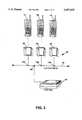
- FIG. 1is a diagrammatic illustration of a vehicle data system in accordance with the present invention, and which may represent a data system associated with a gasoline-powered or battery-powered material handling vehicle such as a forklift truck.
- FIG. 2shows by a similar diagrammatic illustration a fixed data system which may utilize adapters and a local area network corresponding to that of FIG. 1, and may receive terminals from vehicles such as that of FIG. 1, for purposes of interchange of data with a host computer, and for recharging of the terminal batteries.
- FIG. 3shows a vehicle data system which may include the features and components of FIG. 1, and which further provides for plural terminals sharing a common peripheral device means such as a printer.
- FIG. 4shows a further vehicle data system in accordance with the present invention, which is particularly appropriate for product distribution applications and the like, features of FIG. 3 also being applicable to FIG. 4, and the RF link for example of FIG. 4 also being applicable to FIGS. 1-3.
- FIG. 5is a diagram illustrating the various data processing layers of a preferred implementation of local area network and representing message frame construction for an outgoing transmission at the left and the inverse incoming frame reduction at the right, exemplary frame formats for the respective layers being represented centrally of the diagram, and an exemplary physical transmission link being indicated as a horizontal path at the bottom of the diagram (and corresponding to the LAN data bus transmission paths of FIGS. 1-4).
- FIG. 6shows a preferred electrical interface arrangement for coupling each of the terminals and peripheral devices of FIGS. 1-4 with the LAN transmission link of these Figures.
- the illustrated electrical interface of FIG. 6is an example of a "physical layer" as diagrammed in FIG. 5.
- FIG. 7is a somewhat diagrammatic partial vertical sectional view illustrating constructional details of a preferred adapter for the systems of FIGS. 1-4, a portable battery powered terminal corresponding to that of FIG. 1 being shown as being inserted part way into the adapter channel, to the point of initial electrical contact; and also indicating in diagrammatic fashion a laser bar code scanner device in a separate vehicle mounting or holster means and coupled with the terminal via an extendable coiled cable.
- FIG. 8is a somewhat diagrammatic longitudinal sectional view showing the adapter contact assembly of FIG. 7 on a greatly enlarged scale.
- FIG. 9is a diagrammatic bottom plan view of the terminal of FIGS. 1 and 7, illustrating the external contact area of the terminal and also the connector fittings for coupling the terminal with a scanner such as the hand-held laser bar code scanner which is diagrammatically indicated in FIGS. 1 and 7.
- FIG. 10is a diagrammatic illustration of a data collection system carried by a material transport vehicle.
- FIG. 11is a diagrammatic illustration showing the distribution of power from a vehicle system power source.
- FIG. 1shows a system comprised of a portable battery operated data terminal 10 which may be connected through an adapter 11, and a set of peripheral devices such is 12-15 (e.g. devices that might be particularly suited for forklift truck applications), the terminal and peripheral devices being coupled via a local area network data bus 16 of a self-propelled manually steered vehicle 17.
- adapterssuch as 11 may releasably accommodate terminals such as terminal 10 which receive and store data obtained by means of an optical bar code or RF tag scanner 18.
- vehicle poweris generally available from the electrical system of the vehicle.
- Certain electric vehiclessuch as lift trucks may operate from voltages as high as 72 volts, so higher voltage operation must be accommodated as well as the more typical value of twelve volts.
- a preferred LAN configuration for the embodiments of FIGS. 1 through 6may have the characteristics (1) through (4) described in the section headed SUMMARY OF THE INVENTION, and as further detailed hereafter in reference to FIG. 5.
- each LAN connected device in FIGS. 1 through 6A general characteristic of each LAN connected device in FIGS. 1 through 6 is that communication and control intelligence is required to receive and transmit information through the LAN.
- the terminale.g. terminal 10, FIG. 1 with its processor and memory system may serve as a communication controller or primary processor while each peripheral device (such as 12-15, FIG. 1) may comprise a secondary unit which typically contains a microcomputer to perform communication and control tasks.
- Certain applicationsmay involve multiple terminals (such as 21-26, FIG. 2) connected to a single LAN data bus such as vehicle bus 16, FIG. 1, or such as LAN data bus 27 of fixed installation 28, FIG. 2.
- Multiple adapterssuch as 31-36 enable communication from terminal to terminal, and from any of multiple terminals to an RS-232 interface means such as 15, FIG. 1, or 37, FIG. 2.
- Such an interfacemay be used for data interchange with a host computer system overseeing a multiplicity of vehicles (such as 17, FIG. 1) or fixed installations (such as 28, FIG. 2), and may include the LAN controller
- Vehicle mounted terminalssuch as terminal 10, FIG. 1, may be removed from vehicle adapters such as 11 at the end of a working shift and physically inserted into one of the adapters 31-36 of a fixed installation 28 for transfer of accumulated data to a host computer.
- Components 15 and 37may comprise LAN controller and protocol converters for adapting to an external RS-232 transmission system.
- a vehicle such as 17could itself be coupled with a host computer via interface means 15, e.g. while for the case of an electrically driven vehicle, the vehicle batteries were being recharged. In each case, the batteries of terminals such as 21-26, FIG. 2, would be recharged e.g. from AC power as indicated at 38, FIG. 2.
- interface means 15, FIG. 1does not include the LAN controller
- terminals such as 10may be automatically switched when in adapter 11 so as to activate primary LAN programming enabling the microcomputer of terminal 10 to act as the LAN controller when on board vehicle 17.
- the terminalWhen such a terminal 10 is inserted in one of adapters 31-36 on the other hand, the terminal would operate as a standard secondary unit, and be identified dynamically by means of the primary programming of the LAN controller of interface means 37.
- a series of terminalssuch as 41-43 may be coupled with a LAN data bus 44 via respective adapters such as 45-47 which may be part of self propelled manually steered vehicle 48.
- Such multiple terminalscan thus share peripheral devices on board the vehicle such as printer 49.
- the LAN controllermay be external to the terminals, e.g. associated with printer 49 or an interface means such as 15, FIG. 1, or 37, FIG. 2.
- FIG. 4shows a diagram of a data terminal 60 and peripherals 61-67 in an arrangement that might be particularly suited to a route or delivery truck application.
- the LAN communication protocolis preferably designed to coordinate and resolve all of the resultant communication requirements.
- terminal 60may contain programming to act as the LAN controller and may be removably received in a mobile mount adapter 70 of a vehicle 71 which supplies operating and recharging power to the terminal batteries as indicated at 72.
- RF coupling means 67may alternatively contain the network controller and further may couple the LAN data bus 73 with a stationary host so that data from terminal 60 and from measurement means 61-65 may be supplied periodically to a host computer system, and data from the host may be supplied for example to printer 66 as needed.
- FIG. 1shows a diagram of a data terminal 60 and peripherals 61-67 in an arrangement that might be particularly suited to a route or delivery truck application.
- the LAN communication protocolis preferably designed to coordinate and resolve all of the resultant communication requirements.
- LAN data bus 16may have an RF modem coupled therewith, and in each of FIGS. 1, 3 and 4, the terminals may receive scheduling information or the like whenever required during a working day, from a host computer system via an RF link, for example.
- on-line communication with a host computermay be established at any time.
- the network controllerwhen separate from the terminal may contain a special buffer memory for storing data for one or more terminals which may be temporarily disconnected from the network.
- Such network controller and buffer memorymay be part of an RF unit having two-way on-line communication with a host computer, in any of the embodiments of FIGS. 1-4.
- a LAN communication structure for networking multiple portable terminalsmay present unique difficulties since the portable terminals may be removed from the system for various purposes such as those previously described herein. Further it is desirable to provide a system whereby the terminals may be placed in generally random physical network locations by the terminal users. Preferably the terminals may be identified on a dynamic basis as they are added to the local area network, without requiring a unique "hard" terminal address for each terminal which may be associated with the network.
- a unique feature of the preferred LAN protocol of the present inventionis in its structure for addressing that establishes "virtual" rather than permanent physical identification of the communicating devices. This is advantageous in that communication sessions may involve a set of physical devices and connections that are constantly being changed and rearranged (as is common with portable data terminals and their peripherals).
- the implementation of the LAN communication protocolpreferably conforms to the International Standards Organization (ISO) reference model for Open System Interconnection with the functional operations broken into "layers" as diagrammed in FIG. 5.
- ISOInternational Standards Organization
- the physical electrical interface to the LANis preferably as diagrammed in FIG. 6.
- the LAN data busconsists of a balanced two-wire signal pair 91 and 92 conforming to the EIA RS 485 interface standard with tri-state wire-OR capability for the desired multi-drop characteristic.
- the physical communication linkmust be treated as a transmission line with low characteristic impedance, typically 120 ohm. Line termination must be made through resistors such as 93 and 94 of a value equal to that characteristic impedance which results in a relatively high current required to drive a signal on the line.
- a line drive integrated circuit 95is used that has sufficient output capability to provide the necessary output current.
- a typical device that has this capabilityis the Texas Instruments SN75176 type.
- devices of this typeare bipolar circuits that require significantly more operating current that is usually available in a portable product that is powered from batteries.
- power to the line driver integrated circuit as indicated in FIG. 6is switched e.g. by means of a power transistor 97 to minimize the battery current drain.
- Transistor 97is shown as being controlled by a microcomputer 98 which may be part of the portable terminals of FIGS. 1-4.
- each peripheral in FIGS. 1-4may also include a microcomputer for performing the functions of microcomputer 98.
- inactive or physically "not present" terminalsrepresent virtually no loading or effect on the system. It is only when the terminal begins to transmit data that it is known to exist by the network. Consequently, no special switching or isolation is required to remove or replace a terminal from the system.
- a significant difference between the LAN configurations typically used for personal computer networking and communications, and the configuration described here for use with portable data terminalshas to do with the mechanical connector method employed for interface to the electrical network.
- Presently common commercially available LAN productsmay utilize coaxial cables and connectors, twisted pair conductors with some type of connector termination or in some cases, telephone wire with modular phone jacks.
- Each of these physical interface methodsrequires a "fastening” and “unfastening” operation when the attached device is connected and unconnected from the network.
- An important feature of the portable LAN described hereis in its method of electrical connection between the LAN and the connected portable terminal which must be removed and replaced often during operation.
- conductive contacts 111are exposed e.g. at an undersurface of each terminal such as terminal 10, FIG. 1, and each adapter such as 11 is provided with spring loaded mating contacts 110.
- the interface adapterholds the terminal securely in place while aligning the external contacts 111 with the mating contacts fingers 110.
- An additional feature of the LAN interface adapter for mobile mounting applicationsis in its "open face" which allows connection to a scanner such as 18, FIGS. 1 and 7, without impeding the placement and removal of the terminal from the adapter.
- terminal 10is shown in initial contact with the adapter indicated at 11, with a connector 120 leading to scanner 18 located in the open area of the adapter.
- the adaptermay have a contact assembly 125 including spring fingers 110 aligned with respective terminal contacts 111.
- FIG. 8is an enlarged view of contact assembly 125 and shows the initial position of contact finger 110 at 110A, and shows a deflected position at 110B (the terminal being fully inserted into and frictionally held by the adapter to maintain the deflected condition 110B of the spring fingers).
- FIG. 9is a bottom plan view of the terminal 10, showing its set of contacts such as 111, and showing connector fittings at 127 and 128 which may receive the scanner connector 120, FIG. 7.
- adapter 11is shown as comprising a base part 131 which may be notched at 132 to accommodate scanner fitting 120, and a pair of upstanding generally C shaped parts 133 and 134 which define a channel 135 for receiving the terminal 10.
- the parts 133 and 134may have sloping surfaces such as 136, FIG. 7, which limit the downward movement of a terminal into the receiving channel, and serve to frictionally retain the terminal with a suitable degree of pressure between contacts such as 111 and mating spring fingers such as 110.
- U.S. Ser. No. 06/915,023 in a second figure thereofshows a system block diagram including a network controller (NC) with a "RS 485" communications port (91) connected with a "RS 485" multi-drop bus system (75).
- System power from a vehicle power system (30,31,40)is supplied via a power line (PWR) to a series of point of sale registers (14-1 through 17-1) which are coupled to the RS 485 multi-drop bus system (75).
- a conduit (140-1) for power and data (PWR & DATA)contains both a multi-drop data bus and power lines.
- junction boxes (41-1, 51-1, 52-1, 54-1 and 55-1)serve to couple the multi-drop data bus and power lines with the point of sale registers (14-1, 16-1, 17-1). An unused junction box is shown in the PWR & data line.
- the fifth figure of the incorporated applicationshows the distribution of power from a vehicle system power source (e.g. a data processing battery 40-1) to the network controller via a power function box (41-1) and a further junction box (51-1) at the network controller (NC).
- a sixth figureillustrates charging of the data processing battery (40-1) from an alternator via suitable battery isolator means (such as 31-1).
- the ninth figureindicates the segments of conduit (140-IA, 140-IB, 140-IC) between successive junction boxes (41-1, 51-1, 54-1, 55-1, 52-1).
- This same type of power and data conduit systemmay be utilized in the product distribution vehicles (such as forklift trucks and delivery vans) illustrated in FIGS. 1, 3 and 4 herein.
- FIGS. 1, 3 and 4may have devices 11 to 15, 45, 46, 47, 49, 61 to 67 and 70 receiving vehicle power in the same way as shown in the second and fourth figures of the incorporated application Ser. No. 06/915,023, for example, and FIGS. 1 to 4 may be provided with a network controller as shown in the twelfth figure through sixteenth figure (parts A through G) of the incorporated application.
- FIG. 10shows a data collection system carried by a material transport vehicle 400, including a network controller (NC) 401 with a "RS 485" communications port 402 connected with a "RS 485" multidrop bus system 410.
- System power 411may be taken from a vehicle power system such as indicated at 430, 431, 440 in FIG. 11, and is supplied via a power supply path (PWR) indicated at 441, FIG. 10, to a series of mobile mount adapters such as 451-454, which are coupled to the RS 485 multidrop bus system 410.
- NRCnetwork controller
- PWRpower supply path
- a metallic conduit 460 for power and datacontains both multidrop data bus 410 and power lines 461 and 462 of power supply 440.
- Mobile mount adapterssuch as 451-454 serve to couple the multidrop data bus and power lines with the various data devices.
- One or more unused mobile mount adapters or junction boxesmay be connected in the metallic conduit system 460, including those at 471 and 472 which are located interiorly of the vehicle, and a double one at 473 which is conveniently accessible from the exterior of the vehicle.
- FIG. 11shows the distribution of power from a vehicle system power source e.g. a data processing battery 440 to the network controller 401 via a power junction box 480 and a further junction box 481 at the network controller 401.
- FIG. 11also illustrates charging of the data processing battery 440 from an alternator and battery isolator means 431. Segments of metallic conduit extend between successive junction boxes 481, 471, 472, 473, FIG. 11, and also between the successive mobile mount adapters such as 451-454, FIG. 10, and between e.g. junction box 473, FIG. 11, and successive following mobile mount adapters.
- the present disclosurerepresents significant improvements over the incorporated application, for example in providing one or more mobile mount adapters such as 11, FIG. 1, 45, 46, 47, FIG. 3, and 70, FIG. 4, on a multi-drop data bus with diverse peripheral devices such as 12 to 15, FIG. 1, 49, FIG. 3, and 61 to 67, FIG. 4. Further, various devices may be added to the system on a dynamic basis during system operation, and assigned addresses as they become active on the network.
- conduit system containing the LAN data bus and power supply conductorsmay also contain a charging power line for supplying charging power to one of the contact fingers 116 which mates with the charging current input contact e.g. IIIA, FIG. 9, of the terminal 10.
- terminal 10 of the present disclosuremay incorporate the terminal system (27-10A) and battery pack (27-10B) of the twenty-seventh figure.
- a charger (27-22)may be mounted adjacent mobile mount adapter 11 and receive charging power from the vehicle. Where the vehicle system supplies power at a relatively high voltage such as seventy-two volts, preferably such voltage is reduced to a lower voltage value such as twelve volts at a location near the vehicle power source and then power at such lower voltage value is supplied by a suitable cable to the charger component (27-22).
- the chargerhas terminals labeled +CHARGE, TEMP, GND, CHG CONTROL which would be connected to four of the spring fingers 110, FIG. 7, of the mobile mount adapter 11.
- the other two spring fingers 110would be connected to the lines LAN+ DATA and LAN-DATA of the twenty-seventh figure which would correspond with LAN data bus 16, FIG. 1.
- the LAN interface (27-39) of the twenty seventh figurewould include line driver/receiver 95, FIG. 6, which would receive +5 volts and the Power control signal from the microcomputer of the terminal system (27-10A) of the twenty-seventh figure.
- the terminal 10may correspond with that described in the pending application to George E. Chadima, Jr. and Darald R. Schultz Application Serial No. 07/104,653 filed Oct. 2, 1987, "HAND-HELD COMPUTER SYSTEM," abandoned, parent of Application Ser. No. 07/406,822, now U.S. Pat. No. 4,953,113, issued Aug. 28, 1990.
- FIGS. 1, 3 and 4illustrate vehicle data systems for vehicles such as forklift trucks and delivery vans which are utilized in product transport processes and the like.
- vehiclesnormally contain vehicle electric power means associated with the vehicle drive, e.g. a motive power engine driven alternator or generator and vehicle storage battery for use in starting the engine, or electric storage batteries which themselves provide the propulsion energy.
- the vehicle power represented at 19 in FIG. 1, and at 72 in FIG. 4preferably is derived from the vehicle electric power means.
- Vehicle powermay also energize the LAN devices 12 to 15, FIG. 1, 45, 46, 47 and 49, FIG. 3, and 66 and 67, FIG. 4, as well as the interface circuits for devices 12 to 15, 49 and 61 to 67 which may correspond with LAN interface 95, 97, 98, FIG. 6.
- vehicle poweris supplied via suitable voltage regulator means to points such as 140 and 141 in FIG. 6 as well as to microcomputer 98, for each device permanently associated with the LAN data bus in FIGS. 1, 3 and 4.
- componentssuch as 95, 97, 98 in FIG. 6 are part of a removable device such as terminal 10, FIG. 1, terminals 41, 42, 43, FIG. 3, and 60, FIG. 4, such components may be supplied from battery power carried with the removable device, or from charging power (+CHG) derived from the vehicle electric power means, e.g. 19 or 72.
- the local area network means of FIGS. 1, 3 and 4is preferably powered at least in part from vehicle electric power means and independently of fixed power sources (such as represented at 38 in FIG. 2).
- FIG. 1shows an optical or RF scanner means 18 connected by a cable 150 and cable fitting 120 with a connector of the terminal 10 to form data terminal and scanner means
- parts 10 and 18may be in a single unit as shown for example in a pending application of Phillip Miller, et al, U.S. Ser. No. 07/136,097 filed Dec. 21, 1987, now abandoned, Attorney Docket No. 6231.
- the entire disclosure of this application including the drawingsis incorporated herein by reference.
- the handle 15 of the first and third figures of the incorporated drawings of Ser. 07/136,097may contain a series of external contacts corresponding to contacts 111, FIGS. 7 and 9, for engaging with spring fingers corresponding to fingers 110, FIGS. 7 and 8.
- the receiving channel of the mobile mount adapters of FIGS. 1 through 4would frictionally receive the handgrip part 15 and support the horizontally extended undersurface of the scanner barrel, while providing adequate clearance so as to insure against actuation of the trigger 32 as the scanner and terminal means 10 is inserted into and removed from the various adapters.
- Convenient access to the card receptacle 20 of the incorporated scanner and terminal meanswould thus be provided while the scanner and terminal unit was in place in each adapter. Also the scanner and terminal unit would be held securely to enable normal application of manual pressure to the keyboard segments 11a, 11B.
- the mobile mount adaptersmay contain interface components such as 95, 97, 98 which are energized from vehicle power, and also alternatively an optical coupling may be provided between a light emitting diode and light sensor of the scanner and terminal unit of the incorporated application and the microcomputer 98 within each adapter for accommodating the interchange of data between the scanner and terminal unit and the LAN data bus, e.g. to effect printout of data from the scanner and terminal unit on a printer such as 14, FIG. 1, 49, FIG. 3 or 66, FIG. 4, or to effect transmission of data via component 37, FIG. 2, or 67, FIG. 4.
- interface componentssuch as 95, 97, 98 which are energized from vehicle power
- an optical couplingmay be provided between a light emitting diode and light sensor of the scanner and terminal unit of the incorporated application and the microcomputer 98 within each adapter for accommodating the interchange of data between the scanner and terminal unit and the LAN data bus, e.g. to effect printout of data from the scanner and terminal unit on a printer such as
- the present inventionis particularly directed to an individually manned transport vehicle where the driver of the vehicle is the one concerned with operation of the on board devices. Since the driver at times must devote full attention to guidance of the vehicle, it is particularly appropriate that the data capture devices can be quickly inserted into and removed from mobile mount adapters, so that the driver may be completely unencumbered while driving the vehicle. It is advantageous to have a large area display which can be read at a distance e.g. from the driver seat of the vehicle. Such a display can provide information which is useful in moving from one work location to another, e.g. geographical type information; the display being positioned so that such information can be read at a glance e.g. during a brief stop of the vehicle while the driver remains at the controls of the vehicle.
- Each of the connectorssuch as represented at 161 to 165, FIG. 1, 166 to 169, FIG. 3, and 171 to 173, FIG, 4, may be a standardized quick-connect and quick-disconnect type so that adapters and devices may be interchanged and placed at desired locations about each type of individually manned transport vehicle.
- each connectionsuch as 161 may include a set of spring fingers such as 110 receiving the LAN+ and LAN- connections such as 101, 102, FIG. 6.
- Each devicemay then include an interface such as shown at 95, 97, 98, and power supply means for energizing these components from vehicle electric power, (vehicle electric power being available e.g. from a twelve-volt d.c. plug-in power receptacle adjacent each connection 161-169, 171-173) .
- connectionsuch as 110, 111, FIG. 7, may be maintained by a frictional ball and socket type detent such as indicated at 180, FIG. 7, which seats with an audible click into a terminal recess 181 when correct deflection of spring contacts 110 has been achieved.
- the RT1210 and RT2210 data terminalsare battery powered hand-held two way radio data transceivers with keyboard, LCD display, built in radio communication hardware and support for high performance optical bar code readers. Communication to the portable terminals is accomplished by interfacing an RM2216 terminal multiplexor and RB2212 base transceiver to a host computer through a communication port. The host computer may transmit to or receive data from any selected terminal at any time.
- RT1210 and RT2210 terminalswere originally designed for hand-held operation, they have been used in mobile applications by placing the entire terminal into a receptacle which holds the unit firmly in place and isolates the unit from vibration and shock. Power for operation is provided by the terminal battery pack.
- Literature pertaining to the commercially available componentsis shown in APPENDIX B of incorporated Patent Application Ser. No. 07/305,302.
- FIG. 7shows a holster 190 on base 131 for receiving and securely retaining a scanner such as 18, e.g. by a resilient liner 191 of the holster 190 frictionally engaging with a barrel 192 of the scanner.
- the holster 190may be constructed e.g. at 193 to hold the handgrip part 194 and trigger 195 clear thereof so that the scanner of FIG. 7 is quickly and easily removed by manually grasping the handgrip part 194, and so that the trigger 195 will not be actuated as the scanner is manually inserted into the holster.
- the scanner for bar codesneed not be physically attached to the terminal.
- a lot of the software effort involvedmay represent the accommodation of the periodic removal of major sections of the system to do remote scanning of marginally accessible codes.
- the scanneris always attached to the terminal by a pendant cable and if the code to be scanned is beyond the reach of the cable then the terminal must necessarily be removed from its holster.
- the terminalmay represent a very significant portion of a "LAN" system and to remove it in this fashion may disable the system generally. placing the terminal in its holster again may entail the reestablishment of the hierarchial or virtual address structure that was established prior to the removal of the terminal.
- the terminalsnow incorporate various types of scanner interfaces. Some of them have been add-on devices to accommodate scanner types manufactured by third parties. Others have been built-in and have been used to communicate with scanners such as shown in U.S. Pat. No. 4,766,300. Some of these hand-held terminal devices provide power converters accommodating the requirements idiosyncratic to specific scanner types. All of such scanners directly draw power from the terminal, reducing operational time per battery charge.
- a scanner such as 18, FIG. 7,may be operated while disconnected from the terminal on a permanent basis. Terminals presently connect with a host by an RF link and maintain contact without benefit of cable. Of course, terminals mounted on a vehicle will be drawing their power from the vehicular electrical system. The power requirements for a scanner connected by cable to a terminal on a vehicle as in FIG. 7 will not be a large factor in the power budget imposed upon the terminal.
- Detaching the terminal from the scanner completelyprovides benefits in the area of flexibility and ease of use. Since the scanner doesn't require contact with or attachment to the terminal the job of providing operating power no longer is the province of the terminal. The scanner, being completely portable would require its own battery pack but this pack would not have to be unusually capacious. Once the scanning function has been performed the scanner can be reinserted in its holster on the vehicle and charged back up to full capacity from vehicle power by its own charger.
- the communication link replacing cable 150, FIG. 7,may be ultrasonic but could also be infrared or even another very low power RF link.
- Various modulation and demodulation schemescould be employed and the choice of the most appropriate means of encoding data on the channel would depend greatly upon the channel type used. Once the code had been read, the link between the scanner and the terminal could employ one of the various error checking and correcting procedures.
- the terminalswould still incorporate a form of scanner interface but the link would not be mechanical. It would be desirable to provide a bi-directional data path.
- the scannerwould include the matching interface to implement the link and using a bi-directional data path the scanner could receive an acknowledgement after a scan. Reception of such an acknowledgement would constitute an indication of a valid scan and the illumination of an indicator light would provide operator feedback. The lack of a response from the terminal in a specified time period would constitute a negative acknowledgement and another indication on the scanner would signal the operator that another scan was necessary.
- Appropriate scanners for this type of operationwould include current wand and modified CCD type scanners of Norand Corporation and a number of other manufacturer's laser scanners.
- This scannerwould be used typically, by a forklift operator in close proximity to his vehicle. Limited range would not be a significant deterrent here and may even be a benefit in an operation where multiple units are in use.
Landscapes
- Engineering & Computer Science (AREA)
- Physics & Mathematics (AREA)
- Theoretical Computer Science (AREA)
- Electromagnetism (AREA)
- General Physics & Mathematics (AREA)
- General Health & Medical Sciences (AREA)
- Toxicology (AREA)
- Artificial Intelligence (AREA)
- Computer Vision & Pattern Recognition (AREA)
- Health & Medical Sciences (AREA)
- General Engineering & Computer Science (AREA)
- Signal Processing (AREA)
- Computer Networks & Wireless Communication (AREA)
- Computer Hardware Design (AREA)
- Mechanical Engineering (AREA)
- Human Computer Interaction (AREA)
- Computing Systems (AREA)
- Quality & Reliability (AREA)
- Automation & Control Theory (AREA)
- Selective Calling Equipment (AREA)
- Mobile Radio Communication Systems (AREA)
Abstract
Description
______________________________________ U.S. SER. NO. FILING DATE NAMED INVENTORS ______________________________________ 07/305,302 01-31-89 Phillip Miller (ABANDONED) Steven E. Koenck Joseph J. Kubler Keith K. Cargin, Jr. George E. Hanson Patrick H. Davis 07/347,602 05-03-89 Phillip Miller (ABANDONED) Steven E. Koenck Jerry L. Walter Joseph J. Kubler Keith K. Cargin, Jr. George E. Hanson Patrick H. Davis Steven R. Kunert Darald R. Schultz ______________________________________ The foregoing copending applications refer to the following earlier applications pursuant to 35 U.S.C. 120, and reference is hereby made to these earlier applications herein in accordance with the provisions of 35 U.S.C. 120:
______________________________________ U.S. SER. NO. FILING DATE NAMED INVENTORS ______________________________________ 06/915,023 10-03-86 Keith K. Cargin, Jr. (Abandoned) George E. Hanson Phillip Miller 06/928,916 11-07-86 Keith K. Cargin, Jr. (Abandoned - George E. Hanson parent of 07/212,435) 07/212,435 06-28-88 Keith K. Cargin, Jr. (U.S. 5,023,823) George E. Hanson 07/136,097 12-21-87 Phillip Miller (Abandoned) Jerry L. Walter Darrell L. Boatwright 07/327,660 03-23-89 Patrick H. Davis (Abandoned - parent of 07/551,663, now U.S. 5,052,943) 07/339,330 04-14-89 Keith K. Cargin, Jr. (Abandoned) Stephen J. Kelly Kevin Lewis Fischer William T. Gibbs Darrell L. Boatwright Dennis Alan Durbin 07/345,200 04-28-89 George E. Hanson (Abandoned) 07/346,771 05-02-89 Phillip Miller (Abandoned) Steven E. Koenck Jerry L. Walter Joseph J. Kubler Keith K. Cargin, Jr. George E. Hanson Patrick H. Davis Steven R. Kunert Darald R. Schultz 07/347,849 May 3, 1989 Phillip Miller (now abandoned) Robert J. Traeger Joseph J. Kubler Keith K. Cargin, Jr. George E. Hanson Patrick H. Davis Darald R. Schultz 07/784,748 Oct. 28, 1991 Phillip Miller (now U.S. Pat. No. Robert J. Traeger 5,195,183) Joseph J. Kubler Keith K. Cargin, Jr. George E. Hanson Patrick H. Davis Darald R. Schultz 07/922,879 July 31, 1992 Phillip Miller (now U.S. Pat. No. Robert J. Traeger 5,371,858) Joseph J. Kubler Keith K. Cargin, Jr. George E. Hanson Patrick H. Davis Darald R. Schultz 07/347,298 05-02-89 Phillip Miller (Abandoned) Robert J. Traeger Joseph J. Kubler Keith K. Cargin, Jr. George E. Hanson Patrick H. Davis Darald R. Schultz 07/266,537 11-02-88 Steven E. Koenck (Abandoned - a 03-15-88 continuation-in-part of 07/168,352 (U.S. 4,885,523) 07/104,653 10-02-87 George E. Chadima, Jr. (Abandoned - Darald R. Schultz parent of 07/406,822, now U.S. 4,953,113) 07/227,195 08-02-88 George E. Chadima, Jr. (Abandoned) Darald R. Schultz ______________________________________
Claims (25)
Priority Applications (4)
| Application Number | Priority Date | Filing Date | Title |
|---|---|---|---|
| US07/947,820US5457629A (en) | 1989-01-31 | 1992-09-18 | Vehicle data system with common supply of data and power to vehicle devices |
| US08/480,587US5694318A (en) | 1986-10-03 | 1995-06-07 | Vehicular data system for communicating with remote host |
| US08/984,337US5895431A (en) | 1989-01-31 | 1997-12-02 | Communication system used to assist deliveries of goods or services |
| US08/982,750US5928292A (en) | 1986-10-03 | 1997-12-02 | Vehicular data system for communicating with remote host |
Applications Claiming Priority (3)
| Application Number | Priority Date | Filing Date | Title |
|---|---|---|---|
| US30530289A | 1989-01-31 | 1989-01-31 | |
| US34760289A | 1989-05-03 | 1989-05-03 | |
| US07/947,820US5457629A (en) | 1989-01-31 | 1992-09-18 | Vehicle data system with common supply of data and power to vehicle devices |
Related Parent Applications (2)
| Application Number | Title | Priority Date | Filing Date |
|---|---|---|---|
| US30530289AContinuation-In-Part | 1986-08-08 | 1989-01-31 | |
| US34760289AContinuation-In-Part | 1986-08-08 | 1989-05-03 |
Related Child Applications (1)
| Application Number | Title | Priority Date | Filing Date |
|---|---|---|---|
| US08/480,587ContinuationUS5694318A (en) | 1986-10-03 | 1995-06-07 | Vehicular data system for communicating with remote host |
Publications (1)
| Publication Number | Publication Date |
|---|---|
| US5457629Atrue US5457629A (en) | 1995-10-10 |
Family
ID=46247756
Family Applications (4)
| Application Number | Title | Priority Date | Filing Date |
|---|---|---|---|
| US07/947,820Expired - LifetimeUS5457629A (en) | 1986-10-03 | 1992-09-18 | Vehicle data system with common supply of data and power to vehicle devices |
| US08/480,587Expired - LifetimeUS5694318A (en) | 1986-10-03 | 1995-06-07 | Vehicular data system for communicating with remote host |
| US08/982,750Expired - LifetimeUS5928292A (en) | 1986-10-03 | 1997-12-02 | Vehicular data system for communicating with remote host |
| US08/984,337Expired - Fee RelatedUS5895431A (en) | 1989-01-31 | 1997-12-02 | Communication system used to assist deliveries of goods or services |
Family Applications After (3)
| Application Number | Title | Priority Date | Filing Date |
|---|---|---|---|
| US08/480,587Expired - LifetimeUS5694318A (en) | 1986-10-03 | 1995-06-07 | Vehicular data system for communicating with remote host |
| US08/982,750Expired - LifetimeUS5928292A (en) | 1986-10-03 | 1997-12-02 | Vehicular data system for communicating with remote host |
| US08/984,337Expired - Fee RelatedUS5895431A (en) | 1989-01-31 | 1997-12-02 | Communication system used to assist deliveries of goods or services |
Country Status (1)
| Country | Link |
|---|---|
| US (4) | US5457629A (en) |
Cited By (51)
| Publication number | Priority date | Publication date | Assignee | Title |
|---|---|---|---|---|
| US5745794A (en)* | 1995-05-18 | 1998-04-28 | Symbol Technologies, Inc. | System for converting signals into a predetermined data exchange format with plug-in modular connector having voltage, ground, data, and clock terminals for a scanning head |
| WO1998054843A1 (en)* | 1997-05-29 | 1998-12-03 | 3Com Corporation | Power transfer apparatus for concurrently transmitting data and power over data wires |
| US5938721A (en)* | 1996-10-24 | 1999-08-17 | Trimble Navigation Limited | Position based personal digital assistant |
| WO1999045519A3 (en)* | 1998-03-06 | 1999-11-25 | Mobile Information System Inc | Fleet management system and method |
| US6087952A (en)* | 1998-03-06 | 2000-07-11 | Mobile Information Systems, Inc. | Remote mobile data suite and method |
| US6097761A (en)* | 1997-02-11 | 2000-08-01 | U.S. Philips Corporation | Method and system for the transmission of data and power |
| US6411899B2 (en) | 1996-10-24 | 2002-06-25 | Trimble Navigation Ltd. | Position based personal digital assistant |
| WO2002032722A3 (en)* | 2000-10-17 | 2002-08-01 | Lear Corp | Vehicle universal docking station and electronic feature modules |
| US20030046451A1 (en)* | 1997-03-07 | 2003-03-06 | Mobile Information System, Inc. | System and method for mobile data processing and transmission |
| WO2003021881A1 (en)* | 2001-08-31 | 2003-03-13 | Motorola, Inc. A Corporation Of The State Of Delaware | Vehicle active network with data encryption |
| US6600418B2 (en) | 2000-12-12 | 2003-07-29 | 3M Innovative Properties Company | Object tracking and management system and method using radio-frequency identification tags |
| US6669089B2 (en) | 2001-11-12 | 2003-12-30 | 3M Innovative Properties Co | Radio frequency identification systems for asset tracking |
| US20040038717A1 (en)* | 1992-03-18 | 2004-02-26 | Mahany Ronald L. | Transaction control system including portable data terminal and mobile customer service station |
| US20040044667A1 (en)* | 1993-12-23 | 2004-03-04 | Mahany Ronald L. | Enhanced mobility and address resolution in a wireless premises based network |
| US20040090945A1 (en)* | 1996-04-04 | 2004-05-13 | Mahany Ronald L. | Wireless personal local area network |
| US6899539B1 (en) | 2000-02-17 | 2005-05-31 | Exponent, Inc. | Infantry wearable information and weapon system |
| US6963146B2 (en) | 2001-02-07 | 2005-11-08 | Teleflex Incorporated | Modular power control apparatus |
| US20060064208A1 (en)* | 2004-09-22 | 2006-03-23 | Heinrich Lang | System for transmitting signals in a motor vehicle |
| US20060171329A1 (en)* | 2005-01-28 | 2006-08-03 | Jeffrey Ying | Control network with data and power distribution |
| US20060233161A1 (en)* | 1990-05-25 | 2006-10-19 | Koenck Steven E | Multi-level hierarchical radio-frequency communication system |
| US20070147938A1 (en)* | 2005-12-13 | 2007-06-28 | Zih Corp. | Printer encoder adapted for positioning aboard a mobile unit |
| EP1625974A3 (en)* | 1999-09-14 | 2008-01-02 | Andreas Peiker | Arrangement for operating a handheld transceiver. |
| US7447144B2 (en) | 2000-09-21 | 2008-11-04 | Serconet, Ltd. | Telephone communication system and method over local area network wiring |
| US7483417B2 (en) | 1996-04-18 | 2009-01-27 | Verizon Services Corp. | Telephony communication via varied redundant networks |
| US7505785B2 (en) | 1993-10-13 | 2009-03-17 | Dataquill Limited | Data entry systems |
| US7522615B2 (en) | 2002-11-13 | 2009-04-21 | Serconet, Ltd. | Addressable outlet, and a network using same |
| US7627002B1 (en)* | 2002-09-09 | 2009-12-01 | Aruba Networks, Inc. | Mechanism for deploying an access point within a WLAN using a single interconnect |
| US7664097B2 (en) | 1996-04-18 | 2010-02-16 | Verizon Services Corp. | Telephone service via networking |
| US20100039247A1 (en)* | 2006-12-13 | 2010-02-18 | Ziegler Ronald L | Impact sensing usable with fleet management system |
| US20100228428A1 (en)* | 2006-12-13 | 2010-09-09 | Crown Equipment Corporation | Information system for industrial vehicles |
| US7805542B2 (en) | 1997-02-25 | 2010-09-28 | George W. Hindman | Mobile unit attached in a mobile environment that fully restricts access to data received via wireless signal to a separate computer in the mobile environment |
| US7813332B1 (en) | 1997-03-19 | 2010-10-12 | Verizon Services Corp. | Voice call alternative routing through PSTN and internet networks |
| US7817619B1 (en) | 1996-12-18 | 2010-10-19 | Verizon Services Corp. | Internet long distance telephone service |
| US7830860B2 (en) | 1997-03-11 | 2010-11-09 | Verizon Services Corp. | Packet data network voice call quality monitoring |
| US7830858B2 (en) | 1998-07-28 | 2010-11-09 | Mosaid Technologies Incorporated | Local area network of serial intelligent cells |
| US7835344B1 (en) | 1997-03-19 | 2010-11-16 | Verizon Services Corp. | Transport of caller identification information through diverse communication networks |
| US7835386B2 (en) | 1999-07-07 | 2010-11-16 | Mosaid Technologies Incorporated | Local area network for distributing data communication, sensing and control signals |
| US20110022442A1 (en)* | 2006-12-13 | 2011-01-27 | Crown Equipment Corporation | Information system for industrial vehicles including cyclical recurring vehicle information message |
| US20110040440A1 (en)* | 2009-08-12 | 2011-02-17 | Crown Equipment Corporation | Information system for industrial vehicles |
| US7948968B2 (en) | 1997-09-16 | 2011-05-24 | Verizon Communications Inc. | Network session management |
| US8060400B2 (en) | 2006-12-13 | 2011-11-15 | Crown Equipment Corporation | Fleet management system |
| US8155012B2 (en) | 1998-04-10 | 2012-04-10 | Chrimar Systems, Inc. | System and method for adapting a piece of terminal equipment |
| US8363797B2 (en) | 2000-03-20 | 2013-01-29 | Mosaid Technologies Incorporated | Telephone outlet for implementing a local area network over telephone lines and a local area network using such outlets |
| US8873586B2 (en) | 2000-04-19 | 2014-10-28 | Conversant Intellectual Property Management Incorporated | Network combining wired and non-wired segments |
| US8938062B2 (en) | 1995-12-11 | 2015-01-20 | Comcast Ip Holdings I, Llc | Method for accessing service resource items that are for use in a telecommunications system |
| US9191505B2 (en) | 2009-05-28 | 2015-11-17 | Comcast Cable Communications, Llc | Stateful home phone service |
| US9282144B2 (en) | 2011-01-14 | 2016-03-08 | Bae Systems Plc | Unmanned vehicle selective data transfer system and method thereof |
| US9613332B2 (en) | 2014-07-31 | 2017-04-04 | Blue Point Tec LLC | Devices, systems and methods for tracking and auditing shipment items |
| US11032353B2 (en) | 2004-01-13 | 2021-06-08 | May Patents Ltd. | Information device |
| US11225404B2 (en) | 2006-12-13 | 2022-01-18 | Crown Equipment Corporation | Information system for industrial vehicles |
| US12380373B2 (en) | 2009-09-01 | 2025-08-05 | Crown Equipment Corporation | Information system for industrial vehicles including cyclical recurring vehicle information message |
Families Citing this family (87)
| Publication number | Priority date | Publication date | Assignee | Title |
|---|---|---|---|---|
| US7077327B1 (en)* | 1990-09-17 | 2006-07-18 | Metrologic Instruments, Inc. | System for reading bar code symbols using bar code readers having RF signal transmission links with base stations |
| WO1999044302A1 (en)* | 1998-02-27 | 1999-09-02 | Sommer Allibert-Lignotock Gmbh | Handsfree talking system for a mobile telephone |
| KR100513793B1 (en)* | 1998-03-30 | 2005-12-08 | 삼성전자주식회사 | Apparatus for making monitor |
| US6594051B1 (en)* | 1998-03-31 | 2003-07-15 | Radix Micro Devices Plc | Data communication system for hand-held computers |
| US6694366B1 (en)* | 1998-04-29 | 2004-02-17 | Symbol Technologies, Inc. | Data reconciliation between a computer and a mobile data collection terminal |
| US6170026B1 (en) | 1998-06-16 | 2001-01-02 | Modubility Llc | Mobile computing systems which automatically reconfigure to operate any devices attached to a docking module upon connection to the docking station |
| US20100030838A1 (en)* | 1998-08-27 | 2010-02-04 | Beepcard Ltd. | Method to use acoustic signals for computer communications |
| IL127569A0 (en) | 1998-09-16 | 1999-10-28 | Comsense Technologies Ltd | Interactive toys |
| US6607136B1 (en) | 1998-09-16 | 2003-08-19 | Beepcard Inc. | Physical presence digital authentication system |
| US7334735B1 (en)* | 1998-10-02 | 2008-02-26 | Beepcard Ltd. | Card for interaction with a computer |
| US6295492B1 (en)* | 1999-01-27 | 2001-09-25 | Infomove.Com, Inc. | System for transmitting and displaying multiple, motor vehicle information |
| US6488209B1 (en)* | 1999-01-29 | 2002-12-03 | Intermec Ip Corp. | Automatic data collection device that dynamically wedges data transmitted to data consumers |
| USD436604S1 (en) | 1999-04-12 | 2001-01-23 | Clark Equipment Company | Display panel for power machine |
| USD439257S1 (en) | 1999-04-12 | 2001-03-20 | Clark Equipment Company | Display panel for power machine |
| USD434425S (en)* | 1999-04-12 | 2000-11-28 | Clark Equipment Company | Display panel for power machine |
| US6202014B1 (en) | 1999-04-23 | 2001-03-13 | Clark Equipment Company | Features of main control computer for a power machine |
| US7346374B2 (en) | 1999-05-26 | 2008-03-18 | Johnson Controls Technology Company | Wireless communications system and method |
| EP1246414B1 (en)* | 1999-05-26 | 2012-05-23 | Johnson Controls Technology Company | Wireless communications system and method therefor |
| US6343237B1 (en) | 1999-06-04 | 2002-01-29 | Clark Equipment Company | User interface functionality for power machine control system |
| US6367022B1 (en)* | 1999-07-14 | 2002-04-02 | Visteon Global Technologies, Inc. | Power management fault strategy for automotive multimedia system |
| US6393573B1 (en)* | 1999-07-14 | 2002-05-21 | Visteon Global Technologies, Inc. | Power management for automotive multimedia system |
| US8019609B2 (en) | 1999-10-04 | 2011-09-13 | Dialware Inc. | Sonic/ultrasonic authentication method |
| US6923285B1 (en) | 2000-02-01 | 2005-08-02 | Clark Equipment Company | Attachment control device |
| DE10010841A1 (en)* | 2000-03-09 | 2001-09-27 | Hansa Metallwerke Ag | Documentation device |
| US20020173885A1 (en) | 2001-03-13 | 2002-11-21 | Lowrey Larkin Hill | Internet-based system for monitoring vehicles |
| US6636790B1 (en) | 2000-07-25 | 2003-10-21 | Reynolds And Reynolds Holdings, Inc. | Wireless diagnostic system and method for monitoring vehicles |
| US6957133B1 (en) | 2003-05-08 | 2005-10-18 | Reynolds & Reynolds Holdings, Inc. | Small-scale, integrated vehicle telematics device |
| US7228211B1 (en) | 2000-07-25 | 2007-06-05 | Hti Ip, Llc | Telematics device for vehicles with an interface for multiple peripheral devices |
| US6604033B1 (en) | 2000-07-25 | 2003-08-05 | Networkcar.Com | Wireless diagnostic system for characterizing a vehicle's exhaust emissions |
| US7904219B1 (en) | 2000-07-25 | 2011-03-08 | Htiip, Llc | Peripheral access devices and sensors for use with vehicle telematics devices and systems |
| DE10038242B4 (en)* | 2000-08-04 | 2014-07-17 | Bayerische Motoren Werke Aktiengesellschaft | Use of data of a mobile data processing device in a navigation system |
| US6909907B1 (en)* | 2000-11-10 | 2005-06-21 | Pharos Science & Applications, Inc. | Integrated connection assembly for global positioning system (GPS) receiver and personal digital assistance (PDA) device or cellular phones |
| US6550562B2 (en)* | 2000-12-08 | 2003-04-22 | Clark Equipment Company | Hand grip with microprocessor for controlling a power machine |
| US6611740B2 (en) | 2001-03-14 | 2003-08-26 | Networkcar | Internet-based vehicle-diagnostic system |
| US7523159B1 (en) | 2001-03-14 | 2009-04-21 | Hti, Ip, Llc | Systems, methods and devices for a telematics web services interface feature |
| US9219708B2 (en) | 2001-03-22 | 2015-12-22 | DialwareInc. | Method and system for remotely authenticating identification devices |
| US6609082B2 (en) | 2001-03-22 | 2003-08-19 | David S. Wagner | Machine control device |
| US6580985B2 (en)* | 2001-04-17 | 2003-06-17 | Beat-Sonic Co., Ltd. | Vehicle audio adapter |
| US6879894B1 (en) | 2001-04-30 | 2005-04-12 | Reynolds & Reynolds Holdings, Inc. | Internet-based emissions test for vehicles |
| US6594579B1 (en) | 2001-08-06 | 2003-07-15 | Networkcar | Internet-based method for determining a vehicle's fuel efficiency |
| US6747365B2 (en)* | 2001-08-31 | 2004-06-08 | Motorola, Inc. | Vehicle active network adapted to legacy architecture |
| US7174243B1 (en) | 2001-12-06 | 2007-02-06 | Hti Ip, Llc | Wireless, internet-based system for transmitting and analyzing GPS data |
| US20030115104A1 (en)* | 2001-12-13 | 2003-06-19 | Smith Timothy Jay | Internet-based method and system for managing delivery of goods |
| AUPS049902A0 (en)* | 2002-02-13 | 2002-03-07 | Silverbrook Research Pty. Ltd. | Methods and systems (ap63) |
| KR100547728B1 (en)* | 2002-12-16 | 2006-01-31 | 삼성전자주식회사 | Handheld terminal |
| US7383188B2 (en)* | 2002-12-23 | 2008-06-03 | Systems Application Engineering, Inc. | Object loading system and method |
| US20040128134A1 (en)* | 2002-12-23 | 2004-07-01 | Sacks Jerry Dennis | Object loading system and method |
| TW576586U (en)* | 2003-02-27 | 2004-02-11 | Lite On Technology Corp | Charger having name card scanner |
| US9520005B2 (en) | 2003-07-24 | 2016-12-13 | Verizon Telematics Inc. | Wireless vehicle-monitoring system |
| US7113127B1 (en) | 2003-07-24 | 2006-09-26 | Reynolds And Reynolds Holdings, Inc. | Wireless vehicle-monitoring system operating on both terrestrial and satellite networks |
| ATE471058T1 (en)* | 2003-09-08 | 2010-06-15 | Nokia Corp | AUTOMOTIVE MOBILE TERMINAL CONNECTION SYSTEM FOR PROVIDING MOBILE TERMINAL FUNCTION TO ENABLE A DYNAMIC EXTERNAL USER INTERFACE |
| US7225065B1 (en) | 2004-04-26 | 2007-05-29 | Hti Ip, Llc | In-vehicle wiring harness with multiple adaptors for an on-board diagnostic connector |
| KR100606837B1 (en)* | 2004-09-03 | 2006-08-01 | 엘지전자 주식회사 | TV interface device of mobile communication terminal using receptacle |
| NL1028421C2 (en)* | 2005-02-28 | 2006-03-16 | Dtm Products B V | Personal digital assistant is for mobile applications and comprises basic frame with front and rear edges, both with connectors |
| US7556203B2 (en)* | 2005-06-27 | 2009-07-07 | Hand Held Products, Inc. | Method and system for linking a wireless hand held optical reader with a base unit or other wireless device |
| US20070143120A1 (en)* | 2005-11-28 | 2007-06-21 | Amit Phadnis | System and method for configuring an input arrangement for a computing device |
| US8438239B2 (en)* | 2006-05-11 | 2013-05-07 | Vocollect, Inc. | Apparatus and method for sharing data among multiple terminal devices |
| US7686216B2 (en) | 2006-06-13 | 2010-03-30 | Hand Held Products, Inc. | Method and apparatus for uniquely associating a bar code reading terminal to a cash register in a retail store network |
| US8850083B2 (en)* | 2006-07-26 | 2014-09-30 | Bosch Automotive Service Solutions, LLC | Data management method and system |
| US8072309B2 (en)* | 2006-09-14 | 2011-12-06 | Crown Equipment Corporation | Systems and methods of remotely controlling a materials handling vehicle |
| US8452464B2 (en)* | 2009-08-18 | 2013-05-28 | Crown Equipment Corporation | Steer correction for a remotely operated materials handling vehicle |
| US9207673B2 (en)* | 2008-12-04 | 2015-12-08 | Crown Equipment Corporation | Finger-mounted apparatus for remotely controlling a materials handling vehicle |
| US8970363B2 (en) | 2006-09-14 | 2015-03-03 | Crown Equipment Corporation | Wrist/arm/hand mounted device for remotely controlling a materials handling vehicle |
| WO2008039649A2 (en)* | 2006-09-14 | 2008-04-03 | Crown Equipment Corporation | Systems and methods of remotely controlling a materials handling vehicle |
| US9645968B2 (en) | 2006-09-14 | 2017-05-09 | Crown Equipment Corporation | Multiple zone sensing for materials handling vehicles |
| US9122276B2 (en) | 2006-09-14 | 2015-09-01 | Crown Equipment Corporation | Wearable wireless remote control device for use with a materials handling vehicle |
| US8154857B2 (en)* | 2007-01-04 | 2012-04-10 | Whirlpool Corporation | Appliance host with multiple service interfaces for coupling multiple consumer electronic devices |
| US7980088B2 (en)* | 2007-01-04 | 2011-07-19 | Whirlpool Corporation | Removable adapter providing a wireless service to removable consumer electronic device |
| US7618295B2 (en)* | 2007-01-04 | 2009-11-17 | Whirlpool Corporation | Adapter and consumer electronic device functional unit |
| WO2008086132A2 (en)* | 2007-01-04 | 2008-07-17 | Whirlpool Corporation | Host and adapter for selectively positioning a consumer electronic device |
| US9281647B2 (en)* | 2007-04-26 | 2016-03-08 | Intelligent Mechatronic Systems Inc. | Pass-through connector |
| US8621855B2 (en)* | 2007-06-08 | 2014-01-07 | Deere & Company | Electro-hydraulic auxiliary mode control |
| DE102007043472A1 (en)* | 2007-09-04 | 2009-03-05 | Jungheinrich Aktiengesellschaft | Truck and remote maintenance system as well as remote maintenance of a truck |
| US8276399B2 (en)* | 2007-09-12 | 2012-10-02 | Whirlpool Corporation | Docking station for a refrigerator |
| US8301330B2 (en)* | 2008-05-02 | 2012-10-30 | General Electric Company | Method and system for providing supplemental services to telematics systems |
| US9522817B2 (en) | 2008-12-04 | 2016-12-20 | Crown Equipment Corporation | Sensor configuration for a materials handling vehicle |
| US8577551B2 (en) | 2009-08-18 | 2013-11-05 | Crown Equipment Corporation | Steer control maneuvers for materials handling vehicles |
| US8731777B2 (en) | 2009-08-18 | 2014-05-20 | Crown Equipment Corporation | Object tracking and steer maneuvers for materials handling vehicles |
| US9058526B2 (en)* | 2010-02-11 | 2015-06-16 | Hand Held Products, Inc. | Data collection module and system |
| US8655544B2 (en) | 2011-02-02 | 2014-02-18 | Kaarya Llc | System and method for tracking vehicle mileage with mobile devices |
| EP2740030A2 (en)* | 2011-08-04 | 2014-06-11 | CONNORS, Robert W. | Content changeable smart phone application for navigable venues and multi-party navigational system |
| CN103347083A (en)* | 2013-07-10 | 2013-10-09 | 延锋伟世通电子科技(上海)有限公司 | Interconnection and mutual control method for vehicle-mounted entertainment system and portable electronic equipment |
| US9525638B2 (en) | 2013-10-15 | 2016-12-20 | Internap Corporation | Routing system for internet traffic |
| GB2563539B (en)* | 2016-03-11 | 2021-08-11 | Walmart Apollo Llc | Apparatuses and methods for providing transportation container temperature control |
| US11641121B2 (en) | 2019-02-01 | 2023-05-02 | Crown Equipment Corporation | On-board charging station for a remote control device |
| MX2021009158A (en) | 2019-02-01 | 2021-09-10 | Crown Equip Corp | Pairing a remote control device to a vehicle. |
| MX2023001754A (en) | 2020-08-11 | 2023-03-07 | Crown Equip Corp | REMOTE CONTROL DEVICE. |
Citations (18)
| Publication number | Priority date | Publication date | Assignee | Title |
|---|---|---|---|---|
| US4345147A (en)* | 1980-11-14 | 1982-08-17 | International Telephone And Telegraph Corporation | Vehicle mounted mobile business data handling system |
| US4396985A (en)* | 1980-01-16 | 1983-08-02 | Omron Tateisi Electronics Co. | Electronic cash register system for food dispensing business |
| US4468750A (en)* | 1978-10-10 | 1984-08-28 | International Business Machines Corporation | Clustered terminals with writable microcode memories & removable media for applications code & transactions data |
| US4558270A (en)* | 1983-09-06 | 1985-12-10 | James P. Liautaud | Battery charging adapter for a battery charger for a portable battery operated transceiver |
| US4588938A (en)* | 1983-09-06 | 1986-05-13 | James P. Liautaud | Battery charger |
| US4680583A (en)* | 1985-01-30 | 1987-07-14 | Northern Telecom Limited | Terminal address assignment in a broadcast transmission system |
| US4684793A (en)* | 1984-07-13 | 1987-08-04 | Erste Wiener Wach- Und Schliessgesellschaft Ag | Device for acquiring, storing and evaluating the data of a checking process |
| US4739183A (en)* | 1985-07-29 | 1988-04-19 | Nippon Soken, Inc. | Local area network for vehicle |
| US4742335A (en)* | 1986-06-18 | 1988-05-03 | Baker Industries, Inc. | Sequential and/or random polling system with virtually instantaneous response time |
| US4751648A (en)* | 1986-03-31 | 1988-06-14 | Halliburton Company | Local area network data transfer system |
| US4756695A (en)* | 1986-06-13 | 1988-07-12 | Amp Incorporated | Local area network interface |
| US4757456A (en)* | 1981-05-19 | 1988-07-12 | Ralph Benghiat | Device and method for utility meter reading |
| US4773032A (en)* | 1984-11-20 | 1988-09-20 | Fujitsu Limited | Terminal input apparatus |
| US4773005A (en)* | 1984-09-07 | 1988-09-20 | Tektronix, Inc. | Dynamic address assignment system |
| US4801786A (en)* | 1984-05-25 | 1989-01-31 | Anatoli Stobbe | Checking system and method for verifying checking stations in a monitoring system |
| US4857716A (en)* | 1986-05-12 | 1989-08-15 | Clinicom Incorporated | Patient identification and verification system and method |
| US5003472A (en)* | 1988-12-05 | 1991-03-26 | Wand Corporation | Apparatus for order entry in a restaurant |
| US5029183A (en)* | 1989-06-29 | 1991-07-02 | Symbol Technologies, Inc. | Packet data communication network |
Family Cites Families (22)
| Publication number | Priority date | Publication date | Assignee | Title |
|---|---|---|---|---|
| US3517266A (en)* | 1967-09-07 | 1970-06-23 | Nippon Electric Co | Intererame side-mounted distribution panelboard |
| US3665164A (en)* | 1970-07-09 | 1972-05-23 | Ricca Data Systems Inc | Apparatus for reading optically cardlike elements and a merchandising system utilizing the same |
| US3826900A (en)* | 1972-10-13 | 1974-07-30 | Ncr | Cordless scanning probe |
| US4002892A (en)* | 1973-09-15 | 1977-01-11 | Zielinski Adolf H | Portable calculator |
| US4017725A (en)* | 1975-01-03 | 1977-04-12 | Litton Business Systems, Inc. | Solar powered portable calculator |
| US4020527A (en)* | 1976-01-02 | 1977-05-03 | Neill Wilbur J O | Grip for a hand held portable device |
| GB1574468A (en)* | 1976-09-30 | 1980-09-10 | Burroughs Corp | Input-output subsystem in a digital data processing system |
| US4074352A (en)* | 1976-09-30 | 1978-02-14 | Burroughs Corporation | Modular block unit for input-output subsystem |
| US4165554A (en)* | 1978-06-12 | 1979-08-28 | Faget Charles J | Hand-held portable calculator assembly |
| US4247882A (en)* | 1979-04-17 | 1981-01-27 | Gould Inc. | Universal input/output system construction for programmable controllers |
| US4390964A (en)* | 1980-09-09 | 1983-06-28 | Burroughs Corporation | Input/output subsystem using card reader-peripheral controller |
| US4409470A (en)* | 1982-01-25 | 1983-10-11 | Symbol Technologies, Inc. | Narrow-bodied, single-and twin-windowed portable laser scanning head for reading bar code symbols |
| US4506344A (en)* | 1982-06-04 | 1985-03-19 | Pitney Bowes Inc. | Hand held electronic postage meter having secure postage meter doors |
| US4553081A (en)* | 1982-06-07 | 1985-11-12 | Norand Corporation | Portable battery powered system |
| US4455523A (en)* | 1982-06-07 | 1984-06-19 | Norand Corporation | Portable battery powered system |
| US4709202A (en)* | 1982-06-07 | 1987-11-24 | Norand Corporation | Battery powered system |
| JPS58219661A (en)* | 1982-06-15 | 1983-12-21 | Sharp Corp | card calculator |
| USD295411S (en) | 1985-03-15 | 1988-04-26 | American Telephone And Telegraph Company, At&T Bell Laboratories | Combined voice and data terminal or similar article |
| USD299234S (en) | 1985-05-17 | 1989-01-03 | Kabushiki Kaisha Toshiba | Data entry terminal for electronic computers |
| US4835372A (en)* | 1985-07-19 | 1989-05-30 | Clincom Incorporated | Patient care system |
| US4924355A (en)* | 1989-04-25 | 1990-05-08 | Dell Corporate Services Corporation | Personal computer having expansion card adapter bracket |
| US5479613A (en)* | 1992-08-05 | 1995-12-26 | International Business Machines Corporation | Real-time ring bandwidth utilization calculator, calculating bandwidth utilization based on occurrences of first and second predetermined bit patterns |
- 1992
- 1992-09-18USUS07/947,820patent/US5457629A/ennot_activeExpired - Lifetime
- 1995
- 1995-06-07USUS08/480,587patent/US5694318A/ennot_activeExpired - Lifetime
- 1997
- 1997-12-02USUS08/982,750patent/US5928292A/ennot_activeExpired - Lifetime
- 1997-12-02USUS08/984,337patent/US5895431A/ennot_activeExpired - Fee Related
Patent Citations (18)
| Publication number | Priority date | Publication date | Assignee | Title |
|---|---|---|---|---|
| US4468750A (en)* | 1978-10-10 | 1984-08-28 | International Business Machines Corporation | Clustered terminals with writable microcode memories & removable media for applications code & transactions data |
| US4396985A (en)* | 1980-01-16 | 1983-08-02 | Omron Tateisi Electronics Co. | Electronic cash register system for food dispensing business |
| US4345147A (en)* | 1980-11-14 | 1982-08-17 | International Telephone And Telegraph Corporation | Vehicle mounted mobile business data handling system |
| US4757456A (en)* | 1981-05-19 | 1988-07-12 | Ralph Benghiat | Device and method for utility meter reading |
| US4558270A (en)* | 1983-09-06 | 1985-12-10 | James P. Liautaud | Battery charging adapter for a battery charger for a portable battery operated transceiver |
| US4588938A (en)* | 1983-09-06 | 1986-05-13 | James P. Liautaud | Battery charger |
| US4801786A (en)* | 1984-05-25 | 1989-01-31 | Anatoli Stobbe | Checking system and method for verifying checking stations in a monitoring system |
| US4684793A (en)* | 1984-07-13 | 1987-08-04 | Erste Wiener Wach- Und Schliessgesellschaft Ag | Device for acquiring, storing and evaluating the data of a checking process |
| US4773005A (en)* | 1984-09-07 | 1988-09-20 | Tektronix, Inc. | Dynamic address assignment system |
| US4773032A (en)* | 1984-11-20 | 1988-09-20 | Fujitsu Limited | Terminal input apparatus |
| US4680583A (en)* | 1985-01-30 | 1987-07-14 | Northern Telecom Limited | Terminal address assignment in a broadcast transmission system |
| US4739183A (en)* | 1985-07-29 | 1988-04-19 | Nippon Soken, Inc. | Local area network for vehicle |
| US4751648A (en)* | 1986-03-31 | 1988-06-14 | Halliburton Company | Local area network data transfer system |
| US4857716A (en)* | 1986-05-12 | 1989-08-15 | Clinicom Incorporated | Patient identification and verification system and method |
| US4756695A (en)* | 1986-06-13 | 1988-07-12 | Amp Incorporated | Local area network interface |
| US4742335A (en)* | 1986-06-18 | 1988-05-03 | Baker Industries, Inc. | Sequential and/or random polling system with virtually instantaneous response time |
| US5003472A (en)* | 1988-12-05 | 1991-03-26 | Wand Corporation | Apparatus for order entry in a restaurant |
| US5029183A (en)* | 1989-06-29 | 1991-07-02 | Symbol Technologies, Inc. | Packet data communication network |
Cited By (122)
| Publication number | Priority date | Publication date | Assignee | Title |
|---|---|---|---|---|
| US20060209777A1 (en)* | 1990-05-25 | 2006-09-21 | Mahany Ronald L | Wireless personal local area network |
| US7510121B2 (en) | 1990-05-25 | 2009-03-31 | Broadcom Corporation | Multi-level hierarchical radio-frequency communication system |
| US20060233161A1 (en)* | 1990-05-25 | 2006-10-19 | Koenck Steven E | Multi-level hierarchical radio-frequency communication system |
| US7471651B2 (en) | 1992-03-18 | 2008-12-30 | Broadcom Corporation | Transaction control system including portable data terminal and mobile customer service station |
| US20040038717A1 (en)* | 1992-03-18 | 2004-02-26 | Mahany Ronald L. | Transaction control system including portable data terminal and mobile customer service station |
| US7505785B2 (en) | 1993-10-13 | 2009-03-17 | Dataquill Limited | Data entry systems |
| US7920898B2 (en) | 1993-10-13 | 2011-04-05 | Dataquill Limited | Data entry systems |
| US8290538B2 (en) | 1993-10-13 | 2012-10-16 | Dataquill Limited | Data entry systems |
| US20040044667A1 (en)* | 1993-12-23 | 2004-03-04 | Mahany Ronald L. | Enhanced mobility and address resolution in a wireless premises based network |
| US7885242B2 (en) | 1993-12-23 | 2011-02-08 | Broadcom Corp. | Enhanced mobility and address resolution in a wireless premises based network |
| US5745794A (en)* | 1995-05-18 | 1998-04-28 | Symbol Technologies, Inc. | System for converting signals into a predetermined data exchange format with plug-in modular connector having voltage, ground, data, and clock terminals for a scanning head |
| US8938062B2 (en) | 1995-12-11 | 2015-01-20 | Comcast Ip Holdings I, Llc | Method for accessing service resource items that are for use in a telecommunications system |
| US20040090945A1 (en)* | 1996-04-04 | 2004-05-13 | Mahany Ronald L. | Wireless personal local area network |
| US8379531B2 (en) | 1996-04-18 | 2013-02-19 | Verizon Services Corp. | Telephony communication via varied redundant networks |
| US7664097B2 (en) | 1996-04-18 | 2010-02-16 | Verizon Services Corp. | Telephone service via networking |
| US7483417B2 (en) | 1996-04-18 | 2009-01-27 | Verizon Services Corp. | Telephony communication via varied redundant networks |
| US8553681B2 (en) | 1996-06-26 | 2013-10-08 | Verizon Services Corp. | Telephone service via packet-switched networking |
| US6266612B1 (en) | 1996-10-24 | 2001-07-24 | Trimble Navigation Limited | Position based personal digital assistant |
| US5938721A (en)* | 1996-10-24 | 1999-08-17 | Trimble Navigation Limited | Position based personal digital assistant |
| US6411899B2 (en) | 1996-10-24 | 2002-06-25 | Trimble Navigation Ltd. | Position based personal digital assistant |
| US7817619B1 (en) | 1996-12-18 | 2010-10-19 | Verizon Services Corp. | Internet long distance telephone service |
| US6097761A (en)* | 1997-02-11 | 2000-08-01 | U.S. Philips Corporation | Method and system for the transmission of data and power |
| US7805542B2 (en) | 1997-02-25 | 2010-09-28 | George W. Hindman | Mobile unit attached in a mobile environment that fully restricts access to data received via wireless signal to a separate computer in the mobile environment |
| US6889139B2 (en) | 1997-03-07 | 2005-05-03 | Sidewinder Holdings Ltd. | System and method for mobile data processing and transmission |
| US20030046451A1 (en)* | 1997-03-07 | 2003-03-06 | Mobile Information System, Inc. | System and method for mobile data processing and transmission |
| US7830860B2 (en) | 1997-03-11 | 2010-11-09 | Verizon Services Corp. | Packet data network voice call quality monitoring |
| US7813332B1 (en) | 1997-03-19 | 2010-10-12 | Verizon Services Corp. | Voice call alternative routing through PSTN and internet networks |
| US7835344B1 (en) | 1997-03-19 | 2010-11-16 | Verizon Services Corp. | Transport of caller identification information through diverse communication networks |
| US20030062991A1 (en)* | 1997-05-29 | 2003-04-03 | 3Com Corporation | Power transfer apparatus for concurrently transmitting data and power over data wires |
| US5994998A (en)* | 1997-05-29 | 1999-11-30 | 3Com Corporation | Power transfer apparatus for concurrently transmitting data and power over data wires |
| US20040160312A1 (en)* | 1997-05-29 | 2004-08-19 | 3Com Corporation | Power transfer apparatus for concurrently transmitting data and power over data wires |
| US6496105B2 (en) | 1997-05-29 | 2002-12-17 | 3Com Corporation | Power transfer apparatus for concurrently transmitting data and power over data wires |
| US6989735B2 (en) | 1997-05-29 | 2006-01-24 | 3Com Corporation | Power transfer apparatus for concurrently transmitting data and power over data wires |
| US7005969B2 (en) | 1997-05-29 | 2006-02-28 | Fisher David A | Power transfer apparatus for concurrently transmitting data and power over data wires |
| WO1998054843A1 (en)* | 1997-05-29 | 1998-12-03 | 3Com Corporation | Power transfer apparatus for concurrently transmitting data and power over data wires |
| US20030058085A1 (en)* | 1997-05-29 | 2003-03-27 | 3Com Corporation | Power transfer apparatus for concurrently transmitting data and power over data wires |
| US6753761B2 (en)* | 1997-05-29 | 2004-06-22 | 3Com Corporation | Power transfer apparatus for concurrently transmitting data and power over data wires |
| US6710704B2 (en)* | 1997-05-29 | 2004-03-23 | 3Com Corporation | Power transfer apparatus for concurrently transmitting data and power over data wires |
| US20040174251A1 (en)* | 1997-05-29 | 2004-09-09 | 3Com Corporation | Power transfer apparatus for concurrently transmitting data and power over data wires |
| US6140911A (en)* | 1997-05-29 | 2000-10-31 | 3Com Corporation | Power transfer apparatus for concurrently transmitting data and power over data wires |
| US6329906B1 (en)* | 1997-05-29 | 2001-12-11 | 3Com Corporation | Power transfer apparatus for concurrently transmitting data and power over data wires |
| US7948968B2 (en) | 1997-09-16 | 2011-05-24 | Verizon Communications Inc. | Network session management |
| US9215254B1 (en) | 1997-09-16 | 2015-12-15 | Verizon Patent And Licensing Inc. | Network session management for telephony over hybrid networks |
| US8976782B1 (en) | 1997-09-16 | 2015-03-10 | Verizon Patent And Licensing Inc. | Network session management for telephony over hybrid networks |
| US6087952A (en)* | 1998-03-06 | 2000-07-11 | Mobile Information Systems, Inc. | Remote mobile data suite and method |
| WO1999045519A3 (en)* | 1998-03-06 | 1999-11-25 | Mobile Information System Inc | Fleet management system and method |
| US8902760B2 (en) | 1998-04-10 | 2014-12-02 | Chrimar Systems, Inc. | Network system and optional tethers |
| US9019838B2 (en) | 1998-04-10 | 2015-04-28 | Chrimar Systems, Inc. | Central piece of network equipment |
| US9049019B2 (en) | 1998-04-10 | 2015-06-02 | Chrimar Systems, Inc. | Network equipment and optional tether |
| US8942107B2 (en) | 1998-04-10 | 2015-01-27 | Chrimar Systems, Inc. | Piece of ethernet terminal equipment |
| US9812825B2 (en) | 1998-04-10 | 2017-11-07 | Chrimar Systems, Inc. | Ethernet device |
| US8155012B2 (en) | 1998-04-10 | 2012-04-10 | Chrimar Systems, Inc. | System and method for adapting a piece of terminal equipment |
| US7986708B2 (en) | 1998-07-28 | 2011-07-26 | Mosaid Technologies Incorporated | Local area network of serial intelligent cells |
| US7852874B2 (en) | 1998-07-28 | 2010-12-14 | Mosaid Technologies Incorporated | Local area network of serial intelligent cells |
| US8867523B2 (en) | 1998-07-28 | 2014-10-21 | Conversant Intellectual Property Management Incorporated | Local area network of serial intelligent cells |
| US7965735B2 (en) | 1998-07-28 | 2011-06-21 | Mosaid Technologies Incorporated | Local area network of serial intelligent cells |
| US8885659B2 (en) | 1998-07-28 | 2014-11-11 | Conversant Intellectual Property Management Incorporated | Local area network of serial intelligent cells |
| US8885660B2 (en) | 1998-07-28 | 2014-11-11 | Conversant Intellectual Property Management Incorporated | Local area network of serial intelligent cells |
| US7830858B2 (en) | 1998-07-28 | 2010-11-09 | Mosaid Technologies Incorporated | Local area network of serial intelligent cells |
| US8325636B2 (en) | 1998-07-28 | 2012-12-04 | Mosaid Technologies Incorporated | Local area network of serial intelligent cells |
| US8908673B2 (en) | 1998-07-28 | 2014-12-09 | Conversant Intellectual Property Management Incorporated | Local area network of serial intelligent cells |
| US7969917B2 (en) | 1998-07-28 | 2011-06-28 | Mosaid Technologies Incorporated | Local area network of serial intelligent cells |
| US7835386B2 (en) | 1999-07-07 | 2010-11-16 | Mosaid Technologies Incorporated | Local area network for distributing data communication, sensing and control signals |
| US8121132B2 (en) | 1999-07-07 | 2012-02-21 | Mosaid Technologies Incorporated | Local area network for distributing data communication, sensing and control signals |
| US8582598B2 (en) | 1999-07-07 | 2013-11-12 | Mosaid Technologies Incorporated | Local area network for distributing data communication, sensing and control signals |
| EP1625974A3 (en)* | 1999-09-14 | 2008-01-02 | Andreas Peiker | Arrangement for operating a handheld transceiver. |
| US6899539B1 (en) | 2000-02-17 | 2005-05-31 | Exponent, Inc. | Infantry wearable information and weapon system |
| US8855277B2 (en) | 2000-03-20 | 2014-10-07 | Conversant Intellectual Property Managment Incorporated | Telephone outlet for implementing a local area network over telephone lines and a local area network using such outlets |
| US8363797B2 (en) | 2000-03-20 | 2013-01-29 | Mosaid Technologies Incorporated | Telephone outlet for implementing a local area network over telephone lines and a local area network using such outlets |
| US8873586B2 (en) | 2000-04-19 | 2014-10-28 | Conversant Intellectual Property Management Incorporated | Network combining wired and non-wired segments |
| US8982904B2 (en) | 2000-04-19 | 2015-03-17 | Conversant Intellectual Property Management Inc. | Network combining wired and non-wired segments |
| US8817779B2 (en) | 2000-09-21 | 2014-08-26 | Conversant Intellectual Property Management Incorporated | Telephone communication system and method over local area network wiring |
| US7447144B2 (en) | 2000-09-21 | 2008-11-04 | Serconet, Ltd. | Telephone communication system and method over local area network wiring |
| US7843799B2 (en) | 2000-09-21 | 2010-11-30 | Mosaid Technologies Incorporated | Telephone communication system and method over local area network wiring |
| US7480233B2 (en) | 2000-09-21 | 2009-01-20 | Serconet Ltd. | Telephone communication system and method over local area network wiring |
| US7489709B2 (en) | 2000-09-21 | 2009-02-10 | Serconet Ltd. | Telephone communication system and method over local area network wiring |
| US8619538B2 (en) | 2000-09-21 | 2013-12-31 | Mosaid Technologies Incorporated | Communication system and method over local area network wiring |
| GB2383694A (en)* | 2000-10-17 | 2003-07-02 | Lear Corp | Vehicle universal docking station and electronic feature modules |
| WO2002032722A3 (en)* | 2000-10-17 | 2002-08-01 | Lear Corp | Vehicle universal docking station and electronic feature modules |
| US6608399B2 (en) | 2000-10-17 | 2003-08-19 | Lear Corporation | Vehicle universal docking station and electronic feature modules |
| GB2383694B (en)* | 2000-10-17 | 2004-08-18 | Lear Corp | Vehicle universal docking station and electronic feature modules |
| US6600418B2 (en) | 2000-12-12 | 2003-07-29 | 3M Innovative Properties Company | Object tracking and management system and method using radio-frequency identification tags |
| US6963146B2 (en) | 2001-02-07 | 2005-11-08 | Teleflex Incorporated | Modular power control apparatus |
| WO2003021881A1 (en)* | 2001-08-31 | 2003-03-13 | Motorola, Inc. A Corporation Of The State Of Delaware | Vehicle active network with data encryption |
| US6669089B2 (en) | 2001-11-12 | 2003-12-30 | 3M Innovative Properties Co | Radio frequency identification systems for asset tracking |
| US7627002B1 (en)* | 2002-09-09 | 2009-12-01 | Aruba Networks, Inc. | Mechanism for deploying an access point within a WLAN using a single interconnect |
| US7990908B2 (en) | 2002-11-13 | 2011-08-02 | Mosaid Technologies Incorporated | Addressable outlet, and a network using the same |
| US7522615B2 (en) | 2002-11-13 | 2009-04-21 | Serconet, Ltd. | Addressable outlet, and a network using same |
| US8295185B2 (en) | 2002-11-13 | 2012-10-23 | Mosaid Technologies Inc. | Addressable outlet for use in wired local area network |
| US7911992B2 (en) | 2002-11-13 | 2011-03-22 | Mosaid Technologies Incorporated | Addressable outlet, and a network using the same |
| US11032353B2 (en) | 2004-01-13 | 2021-06-08 | May Patents Ltd. | Information device |
| US7574287B2 (en)* | 2004-09-22 | 2009-08-11 | Lang Mekra North America, Llc | System for transmitting signals in a motor vehicle |
| US20060064208A1 (en)* | 2004-09-22 | 2006-03-23 | Heinrich Lang | System for transmitting signals in a motor vehicle |
| US20060171329A1 (en)* | 2005-01-28 | 2006-08-03 | Jeffrey Ying | Control network with data and power distribution |
| US7724778B2 (en) | 2005-01-28 | 2010-05-25 | I/O Controls Corporation | Control network with data and power distribution |
| US8477501B2 (en) | 2005-01-28 | 2013-07-02 | I/O Controls Corporation | Network node with integrated power distribution |
| US9170619B2 (en) | 2005-01-28 | 2015-10-27 | I/O Controls Corporation | Network node with integrated power distribution |
| US20070147938A1 (en)* | 2005-12-13 | 2007-06-28 | Zih Corp. | Printer encoder adapted for positioning aboard a mobile unit |
| US9849694B2 (en) | 2005-12-13 | 2017-12-26 | Zih Corp. | Printer encoder adapted for positioning aboard a mobile unit |
| US20110074553A1 (en)* | 2005-12-13 | 2011-03-31 | Zih Corp. | Printer encoder adapted for positioning aboard a mobile unit |
| US20110022442A1 (en)* | 2006-12-13 | 2011-01-27 | Crown Equipment Corporation | Information system for industrial vehicles including cyclical recurring vehicle information message |
| US20100039247A1 (en)* | 2006-12-13 | 2010-02-18 | Ziegler Ronald L | Impact sensing usable with fleet management system |
| US8060400B2 (en) | 2006-12-13 | 2011-11-15 | Crown Equipment Corporation | Fleet management system |
| US8249910B2 (en) | 2006-12-13 | 2012-08-21 | Crown Equipment Corporation | Fleet management system |
| US10600256B2 (en) | 2006-12-13 | 2020-03-24 | Crown Equipment Corporation | Impact sensing usable with fleet management system |
| US20100228428A1 (en)* | 2006-12-13 | 2010-09-09 | Crown Equipment Corporation | Information system for industrial vehicles |
| US12210353B2 (en) | 2006-12-13 | 2025-01-28 | Crown Equipment Corporation | Fleet management system |
| US11947361B2 (en) | 2006-12-13 | 2024-04-02 | Crown Equipment Corporation | Fleet management system |
| US11823502B2 (en) | 2006-12-13 | 2023-11-21 | Crown Equipment Corporation | Impact sensing usable with fleet management system |
| US11225404B2 (en) | 2006-12-13 | 2022-01-18 | Crown Equipment Corporation | Information system for industrial vehicles |
| US10810521B2 (en) | 2006-12-13 | 2020-10-20 | Crown Equipment Corporation | Information system for industrial vehicles including cyclical recurring vehicle information message |
| US9984341B2 (en) | 2006-12-13 | 2018-05-29 | Crown Equipment Corporation | Information system for industrial vehicles including cyclical recurring vehicle information message |
| US10013815B2 (en) | 2006-12-13 | 2018-07-03 | Crown Equipment Corporation | Information system for industrial vehicles |
| US10599160B2 (en) | 2006-12-13 | 2020-03-24 | Crown Equipment Corporation | Fleet management system |
| US9191505B2 (en) | 2009-05-28 | 2015-11-17 | Comcast Cable Communications, Llc | Stateful home phone service |
| US20110040440A1 (en)* | 2009-08-12 | 2011-02-17 | Crown Equipment Corporation | Information system for industrial vehicles |
| US8725345B2 (en) | 2009-08-12 | 2014-05-13 | Crown Equipment Corporation | Information system for industrial vehicles |
| US8583314B2 (en) | 2009-08-12 | 2013-11-12 | Crown Equipment Corporation | Information system for industrial vehicles |
| US12380373B2 (en) | 2009-09-01 | 2025-08-05 | Crown Equipment Corporation | Information system for industrial vehicles including cyclical recurring vehicle information message |
| US9282144B2 (en) | 2011-01-14 | 2016-03-08 | Bae Systems Plc | Unmanned vehicle selective data transfer system and method thereof |
| US9892378B2 (en) | 2014-07-31 | 2018-02-13 | BluePoint Mobile Solutoins, Inc. | Devices, systems and methods for tracking and auditing shipment items |
| US9613332B2 (en) | 2014-07-31 | 2017-04-04 | Blue Point Tec LLC | Devices, systems and methods for tracking and auditing shipment items |
Also Published As
| Publication number | Publication date |
|---|---|
| US5694318A (en) | 1997-12-02 |
| US5895431A (en) | 1999-04-20 |
| US5928292A (en) | 1999-07-27 |
Similar Documents
| Publication | Publication Date | Title |
|---|---|---|
| US5457629A (en) | Vehicle data system with common supply of data and power to vehicle devices | |
| US5289378A (en) | Vehicle lan with adapters for coupling portable data terminals | |
| US5625555A (en) | Data communication system with adapter for removable coupling of portable data terminals | |
| US5465207A (en) | Vehicle data system | |
| US5521370A (en) | Pistol grip hand-held data terminal cooperable with communicating and recharging dock | |
| US5625180A (en) | Data capture system with communicating and recharging docking apparatus and hand-held data terminal means cooperable therewith | |
| US5517434A (en) | Data capture system with communicating and recharging docking apparatus and hand-held data terminal means cooperable therewith | |
| US7004395B2 (en) | Multi-level hierarchical radio-frequency communication system | |
| US6006100A (en) | Multi-level, hierarchical radio-frequency communication system | |
| US5805807A (en) | Multilevel data communication system including local and host systems | |
| US5910776A (en) | Method and apparatus for identifying locating or monitoring equipment or other objects | |
| AU641541B2 (en) | Multi-level radio-frequency communication system | |
| EP1528496B1 (en) | Mail delivery support system | |
| CA2673025C (en) | System and method for communicating status information | |
| US20060255943A1 (en) | Induction charging machine, methods, and system for a data reader | |
| US7918401B2 (en) | Multi-level hierarchical radio-frequency communication system | |
| EP1702291A1 (en) | Optical reader | |
| CN116596418A (en) | Intelligent management system and method for secondary logistics | |
| JP2000103505A (en) | Pallet control system | |
| US20030222142A1 (en) | Retrofit enhancement device for a hand-held data collection unit | |
| WO1998019223A1 (en) | Improved universal power-supply connection system for multiple electronic devices, and devices for use therewith | |
| JPH10182096A (en) | Cargo handling system using id tag and cargo handling method | |
| JPH0777000B2 (en) | Logistics management system | |
| CN215341097U (en) | Operation system for sorting and separating warehouse goods | |
| JPH10207576A (en) | Portable information terminal equipment |
Legal Events
| Date | Code | Title | Description |
|---|---|---|---|
| AS | Assignment | Owner name:FIRST NATIONAL BANK OF CHICAGO, THE, ILLINOIS Free format text:SECURITY INTEREST;ASSIGNOR:NORAND CORPORATION;REEL/FRAME:006478/0471 Effective date:19930201 | |
| AS | Assignment | Owner name:NORAND CORPORATION, IOWA Free format text:SECURITY INTEREST;ASSIGNOR:FIRST NATIONAL BANK OF CHICAGO, THE;REEL/FRAME:007288/0317 Effective date:19930201 | |
| STCF | Information on status: patent grant | Free format text:PATENTED CASE | |
| AS | Assignment | Owner name:FIRST NATIONAL BANK OF CHICAGO, THE, ILLINOIS Free format text:SECURITY INTEREST;ASSIGNOR:NORAND CORPORATION;REEL/FRAME:007795/0717 Effective date:19960126 | |
| FEPP | Fee payment procedure | Free format text:PAYOR NUMBER ASSIGNED (ORIGINAL EVENT CODE: ASPN); ENTITY STATUS OF PATENT OWNER: LARGE ENTITY | |
| AS | Assignment | Owner name:NORAND CORPORATION, IOWA Free format text:RELEASE OF SECURITY INTEREST;ASSIGNOR:FIRST NATIONAL BANK OF CHICAGO, AS COLLATERAL AGENT, THE;REEL/FRAME:009479/0471 Effective date:19970225 | |
| FPAY | Fee payment | Year of fee payment:4 | |
| FEPP | Fee payment procedure | Free format text:PAYOR NUMBER ASSIGNED (ORIGINAL EVENT CODE: ASPN); ENTITY STATUS OF PATENT OWNER: LARGE ENTITY Free format text:PAYER NUMBER DE-ASSIGNED (ORIGINAL EVENT CODE: RMPN); ENTITY STATUS OF PATENT OWNER: LARGE ENTITY | |
| FPAY | Fee payment | Year of fee payment:8 | |
| AS | Assignment | Owner name:INTERMEC IP CORP., WASHINGTON Free format text:ASSIGNMENT OF ASSIGNORS INTEREST;ASSIGNOR:INTERMEC TECHNOLOGIES CORPORATION;REEL/FRAME:016237/0161 Effective date:19990721 Owner name:INTERMEC TECHNOLOGIES CORPORATION, WASHINGTON Free format text:MERGER;ASSIGNOR:NORAND CORPORATION;REEL/FRAME:016237/0153 Effective date:19971219 | |
| FPAY | Fee payment | Year of fee payment:12 |