US5456480A - Fork suspension with variable hydraulic damping - Google Patents
Fork suspension with variable hydraulic dampingDownload PDFInfo
- Publication number
- US5456480A US5456480AUS08/254,755US25475594AUS5456480AUS 5456480 AUS5456480 AUS 5456480AUS 25475594 AUS25475594 AUS 25475594AUS 5456480 AUS5456480 AUS 5456480A
- Authority
- US
- United States
- Prior art keywords
- piston
- shock absorbing
- flow
- struts
- rod
- Prior art date
- Legal status (The legal status is an assumption and is not a legal conclusion. Google has not performed a legal analysis and makes no representation as to the accuracy of the status listed.)
- Expired - Lifetime
Links
- 238000013016dampingMethods0.000titleclaimsabstractdescription72
- 239000000725suspensionSubstances0.000titledescription22
- 230000035939shockEffects0.000claimsabstractdescription78
- 230000006835compressionEffects0.000claimsabstractdescription53
- 238000007906compressionMethods0.000claimsabstractdescription53
- 239000012530fluidSubstances0.000claimsabstractdescription22
- 238000006073displacement reactionMethods0.000claimsabstractdescription13
- 230000001105regulatory effectEffects0.000claimsabstractdescription6
- 230000002093peripheral effectEffects0.000claimsdescription10
- 239000000463materialSubstances0.000claims2
- 230000006872improvementEffects0.000abstractdescription4
- 239000006096absorbing agentSubstances0.000description5
- 230000009471actionEffects0.000description3
- 230000008901benefitEffects0.000description3
- 230000008859changeEffects0.000description2
- 238000004519manufacturing processMethods0.000description2
- 230000004048modificationEffects0.000description2
- 238000012986modificationMethods0.000description2
- 230000004044responseEffects0.000description2
- 230000035945sensitivityEffects0.000description2
- 229910000639Spring steelInorganic materials0.000description1
- 230000002411adverseEffects0.000description1
- 238000010276constructionMethods0.000description1
- 230000003247decreasing effectEffects0.000description1
- 230000003116impacting effectEffects0.000description1
- 230000007246mechanismEffects0.000description1
- 238000000034methodMethods0.000description1
- 230000036961partial effectEffects0.000description1
- 230000036316preloadEffects0.000description1
- 238000003825pressingMethods0.000description1
- 230000008569processEffects0.000description1
- 230000001373regressive effectEffects0.000description1
- 230000000717retained effectEffects0.000description1
- 230000002441reversible effectEffects0.000description1
- 239000011435rockSubstances0.000description1
Images


Classifications
- B—PERFORMING OPERATIONS; TRANSPORTING
- B62—LAND VEHICLES FOR TRAVELLING OTHERWISE THAN ON RAILS
- B62K—CYCLES; CYCLE FRAMES; CYCLE STEERING DEVICES; RIDER-OPERATED TERMINAL CONTROLS SPECIALLY ADAPTED FOR CYCLES; CYCLE AXLE SUSPENSIONS; CYCLE SIDE-CARS, FORECARS, OR THE LIKE
- B62K25/00—Axle suspensions
- B62K25/04—Axle suspensions for mounting axles resiliently on cycle frame or fork
- B62K25/06—Axle suspensions for mounting axles resiliently on cycle frame or fork with telescopic fork, e.g. including auxiliary rocking arms
- B62K25/08—Axle suspensions for mounting axles resiliently on cycle frame or fork with telescopic fork, e.g. including auxiliary rocking arms for front wheel
- F—MECHANICAL ENGINEERING; LIGHTING; HEATING; WEAPONS; BLASTING
- F16—ENGINEERING ELEMENTS AND UNITS; GENERAL MEASURES FOR PRODUCING AND MAINTAINING EFFECTIVE FUNCTIONING OF MACHINES OR INSTALLATIONS; THERMAL INSULATION IN GENERAL
- F16F—SPRINGS; SHOCK-ABSORBERS; MEANS FOR DAMPING VIBRATION
- F16F9/00—Springs, vibration-dampers, shock-absorbers, or similarly-constructed movement-dampers using a fluid or the equivalent as damping medium
- F16F9/32—Details
- F16F9/50—Special means providing automatic damping adjustment, i.e. self-adjustment of damping by particular sliding movements of a valve element, other than flexions or displacement of valve discs; Special means providing self-adjustment of spring characteristics
Definitions
- the present inventionrelates to a shock absorbing system for the front fork of two-wheeled vehicles, especially bicycles. More specifically, the present invention relates to such a shock absorbing system having a hydraulic shock damping unit with variable and adjustable damping characteristics.
- Front fork suspensionshave been known for motorcycles for a long time and with the invention of Turner U.S. Pat. No. 4,971,344, became practical for use on bicycles, and have since found widespread use, particularly on mountain bicycles.
- air pressureis used to adjust the hydraulic fork to compensate for rider weight variations or to produce a firmer or softer ride.
- extension damping performance of the suspensionis directly related to the amount of air pressure in the system, adjusting of the air pressure to compensate for a rider's weight could adversely affect the extension damping characteristics of the suspension, and no other means existed to vary the performance characteristics of the suspension, nor was the suspension designed to produce differing performance characteristics under different loading conditions apart from an ability to "lockout" low level forces of the type produced by pedaling while allowing the fork to react to high impact forces.
- the fork suspension of the above-mentioned Turner patentwas improved to enable varying of the preload on a coil-type compression spring, that acts to hold a compression valve plate of a metering valve located between upper and lower hydraulic chambers in a closed position until a predetermined force level is reached at which time it pops open to allow flow through the valve.
- a coil-type compression springthat acts to hold a compression valve plate of a metering valve located between upper and lower hydraulic chambers in a closed position until a predetermined force level is reached at which time it pops open to allow flow through the valve.
- the coil-type compression springis caused to contract or expand, thereby changing the force required to open the compression metering valve, and allowing a wide range of adjustments for adapting the suspension to widely differing circumstances of rider weight and riding experience.
- this adjustabilitydoes not affect the suspension beyond setting the threshold level at which compression of the fork will commence.
- shock absorbing bicycle forkshave since been developed which allow for personalized adjustment of the performance characteristics of the fork.
- Wilson et al. Pat. No. 5,269,549discloses a suspension for the front wheel of bicycles in which a spring action is used for shock absorbing purposes and is obtained by a skewered arrangement of stacked elastomeric pads which are disposed between the ends of the fork strut tubes to absorb shocks by deformation thereof.
- the shock absorbing characteristicscan be changed in accordance with the rider's weight and the conditions under which the bicycle will be ridden.
- an elastomeric suspensionsimply is incapable of achieving the same kind of ride as a hydraulic suspension in that spring shock absorbing characteristics are a function of the distance they are compressed while a hydraulic suspension has a damping characteristic that is a function of the speed at which the shock absorber is compressed.
- variable damping hydraulic shock absorberswith variable damping characteristics are well known in the automotive and motorcycle field. Examples of such variable damping hydraulic shock absorbers can be found in Van Zeggeren U.S. Pat. No. 5,184,703 and in Yamaoka et at. U.S. Pat. No. 5,277,283. In both of these examples, a plurality of flow orifices are provided to provide a plurality of possible flow paths of differing damping characteristics with means being provided to change the orifices/flow paths for the hydraulic damping fluid to vary the damping characteristics.
- the variation in damping characteristicis produced electronically, and can be locked into one of two positions, i.e., a "sport" setting having a high damping action and a normal setting providing a softer ride due to a low damping action, or damping can be adjusted in response to various driving condition sensors, such as accelerometers, gradient detectors, etc.
- driving condition sensorssuch as accelerometers, gradient detectors, etc.
- the Yamaoka et al. patentseeks to provide stability and comfort during any automotive vehicular driving condition by linearly varying the damping characteristics or damping force of their shock absorber as a function of piston stroke. This result is achieved utilizing a tandem arrangement of orifices having different flow restriction variation characteristics, so that the damping characteristics will vary as a function of piston speed.
- another object of the inventionis to provide a hydraulic shock damping unit in which the compression force characteristic of a piston flow control valve having a leaf spring type valve plate can be effectively adjusted.
- a further object of the inventionis to provide a hydraulic shock damping unit in which the damping characteristic can be made sensitive to the position of the hydraulic piston so that damping is increased as the shock absorber is compressed.
- Yet another object of the present inventionis to obtain the preceding object in a manner which is keyed to a shock absorbing spring unit of the fork, so that changes in spring rate automatically produce corresponding changes in the location sensitivity of the hydraulic unit of the fork.
- Still another objectis to provide a hydraulic shock damping unit which can be preassembled, and then installed and replaced within the fork as a unit.
- a further object of the present inventionis to obtain the foregoing objects in a manner that is practical and economic for use on bicycles and is adjustable and serviceable by the average bicycle rider.
- a shock absorbing front fork for a two-wheeled vehicleparticularly a bicycle
- a shock absorbing front fork for a two-wheeled vehicleparticularly a bicycle
- a shock absorbing front fork for a two-wheeled vehicleparticularly a bicycle
- a bicycleof the type having a pair of telescoping struts, upper tubes of which are interconnected by an upper crown to a steerer tube at an upper end portion thereof and lower tubes of which have means for mounting a wheel axle at a bottom end thereof, and a hydraulically damped shock absorbing arrangement disposed within each of the telescoping struts, said shock absorbing arrangement having a piston which divides a hydraulic fluid containing cylinder into upper and lower chambers, a valve for regulating flow of hydraulic fluid through said piston between the upper and lower chambers, and a piston rod connected to said piston, said piston rod acting on said piston in a first direction upon compression of the telescopic struts.
- a spring means for absorbing shocksthat acts on the piston of the hydraulic shock damping arrangement upon compression of the telescopic struts, and a location sensitive flow control arrangement having a flow path extending between opposite sides of said piston and a flow adjusting element which is displaceable into and out of said flow path.
- the spring meansacts on the flow adjusting arrangement to shift it into said flow path by a distance that is a function of an extent to which said spring means is acted upon in said first direction by compression of the telescopic struts.
- valvecomprises at least one leaf spring disc mounted on an opposite side of the piston from the piston rod and overlying a plurality of passages through said piston.
- the total flow-through area of the passagesis increased as the spring disc is deflected away from the piston, commencing at a peripheral edge of the spring disc, due to pressure increases in said upper chamber due to compression of the struts but such deflection is controlled by an annular resilient pad that is disposed overlying said spring disc.
- a compression damping adjuster shaft having an axially adjustable abutment member thereonis mounted on the opposite side of the piston from the piston rod and this abutment member holds the resilient pad against the spring disc under a holding pressure which is adjustable by axial displacement of the abutment member.
- the hydraulically damped shock absorbing arrangementis formed as a self-contained replaceable cartridge unit detachably mounted within each strut.
- the cartridge unitcomprising a cartridge body which encloses the piston and defines the upper and lower hydraulic fluid chambers in conjunction with the piston, the piston rod sealingly extending through an end wall of the cartridge body.
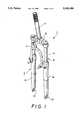
- FIG. 1a perspective view of a front fork for a bicycle incorporating the variable hydraulic damping system of the present invention
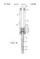
- FIG. 2is a vertical cross-sectional view of a portion of one strut of the FIG. 1 fork;
- FIGS. 3is an enlarged diagrammatic depiction of a location damping arrangement of the variable hydraulic damping system of the present invention
- FIG. 4is an enlarged cross-sectional view depicting a compression damping arrangement of the variable hydraulic damping system of the present invention
- FIG. 5is a perspective illustration of the compression damping adjuster of the compression damping arrangement of FIG. 4;
- FIGS. 6-8are top plan, vertical cross-sectional and bottom plan views of the piston of the compression damping arrangement of FIG. 4;
- FIG. 9is a partial cross-sectional view of a damping unit incorporating the location damping arrangement of FIG. 3 and the compression damping arrangement of FIG. 4.
- FIG. 1shows a shock absorbing front fork 1 for a bicycle of the type having a pair of telescoping struts 3, upper tubes 4 of which are interconnected by an upper crown 5 to a steerer tube 7 at their upper ends.
- the lower tubes 8 of struts 3telescopingly receive the upper tubes 4 in the upper end thereof, and have mounting brackets 10 to which an axle of a front wheel (not shown) is attached at the bottom end the struts.
- a hydraulically damped shock absorbing arrangement 15is disposed within at least one of the telescoping struts 3, it having been found to be sufficient (and acceptable from a fork flexing standpoint) to provide compression damping in only one strut 3 of fork 1, it also being possible to provide the same or a different type of hydraulic damping, or no hydraulic damping, at all in the other strut 3.
- Hydraulically damped shock absorbing arrangement 15includes a piston 16 which divides a hydraulic fluid containing cylinder (formed in this case by the body 19 of a replaceable cartridge unit 20 that is described in detail below) into an upper chamber 21 and lower chamber 22.
- a valve 24shown in enlarged scale in FIG. 4 but omitted from FIGS.
- FIG. 2&3for illustrational simplicity is provided for regulating a flow of hydraulic fluid through the piston 16 between the upper and lower chambers 21, 22, and a piston rod 25 is connected to the piston 16 and acts on piston 16 upon compression of the telescopic struts, Piston rod 25 passes through the top end wall 19a of the cartridge body 19, a seal 26 being provided thereat to prevent leakage.
- the cartridge bodyis retained in the open lower end portion of the upper tube 4 by any suitable means, such as by being provided with an enlarged end portion 19b which is received in an annular recess in the peripheral wall of the upper tube 4 and is held therein by C-shaped, spring retainer clip 28 (FIG. 2) which engages in an annular groove at the lower end of the annular recess in the peripheral wall of the upper tube 4.
- a rod 30extends from the opposite side of piston 16 from piston rod 25, passes through a seal 31 and the lower end wall 19c of the cartridge body 19.
- the end of this rod 30is fixed, such as by a screw, to the bottom end of the lower tube 8.
- a spring means Sacts between a flange 25a, (FIGS. 2 & 3) provided on the outer, upper end of the piston rod 25, and the upper tube 4 of each strut 3.
- the spring meanscan comprise one or more rubber or elastomeric bumpers, as represented in FIG. 2, a coil spring, as represented in FIG. 3, a leaf spring (not shown) or any other suitable compression spring arrangement.
- the location sensitive flow control arrangement 37has a flow path (arrow F) extending between upper fluid-filled chamber 21, on one side of piston 16 and the lower fluid-filled chamber 22 on the opposite side thereof.
- This flow pathpasses through a compression flow inlet port 40 which communicates the upper chamber 21 with an axial passage 25a in the piston rod, which connects with an axial passage 30a in the second rod 30, the axial passage 30a having a compression flow outlet port 38 which communicates the flow from the passage 30a with the lower chamber 22.
- a flow adjusting element 39comprises a flange-like displacement portion 39a, which is engaged by the spring means S, and a flow adjusting shaft 39b which is displaceable into and out of the flow path F so as to progressively block and unblock compression inlet port 40, FIG. 3 showing port 40 being partially blocked and FIG. 2 showing it fully blocked.
- a resilient means formed, for example, by an annular elastomeric pad 42is located between the displacement portion 39a of flow adjusting element 39 and the end 16a of the piston rod 16.
- the location sensitive flow control arrangement 37provides a displacement sensitivity to the inherently speed sensitive hydraulic damping arrangement, but it does so in a way that is linked to the spring rate of the shock absorbing spring S.
- any changes to the spring rateproduced by, e.g., exchanging a stiffer or softer spring means S for the existing one, or by expanding or contracting the spring means S via an adjustment mechanism, simultaneously brings about a corresponding increase or decrease in the damping characteristics of the hydraulic damping arrangement.
- Valve 24comprises at least one shim-type, annular leaf spring disc 45 mounted on the lower side of the piston 16 and a rebound washer 46 on the opposite side of the piston 16.
- a very simple and effective means for holding this entire valve assembly togetherhas been achieved by a screw thread connection 47 between the inner ends of rods 25, 30, clamping the piston 16 and the inner periphery of spring disc(s) 45 between them.
- the spring disc(s) 45overly a plurality of passages 16b through the piston 16 and passages 16c are controlled by rebound washer 46 (FIGS. 6-8).
- annular resilient pad 50is disposed overlying the spring disc(s) 45.
- Pad 50is held against the spring disc(s) 45 by an axially adjustable abutment member in the form of an annular holding disc 52 carried by the rod 30, when rods 25 and 30 are screwed together.
- the holding pressure exerted by annular holding disc 52 pressing the resilient pad 50 against the spring disc(s) 45is adjustable by axial displacement of annular holding disc 52.
- a cross pin 54extends through an axially elongated, diametral slot 30b extending through the rod 30, the rod 30 is formed as a hollow shaft having an axial passage 30c in which an adjustment rod 56 is in an axially adjustable manner, such as by the screw thread connection 57 shown in FIGS. 2 & 5, the lower end of adjustment rod 56 being provided, for example, with an Allen wrench socket 58 (FIG. 9) which is accessible through an opening 8a at the bottom of lower tube 8 (FIG. 2).
- Adjustment rod 56engages the cross pin 54, so that by axial adjustment of the position of the adjustment rod 56 within the hollow shaft of rod 30, the position of the cross pin 54 is axially shifted along the length of the rod 30 in the elongated diametral slot 30b to thereby cause the holding disc 52 to compress the annular resilient pad to a greater or lesser extent.
- the cross pin 54may merely abut on the surface of a holding disc 52 that is washer-shaped (as shown in FIG. 5), preferably, the annular holding disc 52 has a diametrally running receiving groove 52a in which cross pin 54 is received as shown in FIG. 4.
- the cross pin 52can serve to hold itself to the holding disc by being made of a rolled piece of spring steel sheet whose diameter is compressed when the cross pin 52 is forced into the receiving groove 52a, such a form for the cross pin being represented in FIG. 9.
- an O-ring seal 60can be provided around the adjustment rod 56 as represented in FIGS. 4 and/or 9.
- the hydraulically damped shock absorbing arrangementis formed as a self-contained replaceable cartridge unit 20.
- This cartridge unit 20comprises a cartridge body 19 which encloses piston 16 and defines the upper and lower chambers 21, 22 in conjunction with piston 16 which sealingly extends through the top end wall of the cartridge body, and with the rod 30 sealingly extending through the opposite, lower end wall of the cartridge body 19.
- cartridge unit 20instead of the conventional practice of using the tubes of the strut to define the hydraulic cylinder, advantages are achieved from both a manufacturing standpoint and a especially from servicing standpoint.
- the described location sensitive flow control arrangementcan be used without the compression damping valve adjustment feature and vice verse.
- the cartridge unit concept of the present inventioncan be used with either, neither or both of the noted location sensitive flow control and the compression damping valve adjustment features.
- motor vehicle shock absorbing damping systemshave not been adaptable to the needs of bicycles, those skilled in the art will recognize how the basic features of the present invention, such as the location sensitive flow control arrangement and the cartridge unit concept, while intended for a bicycle fork, will find direct applicability to shock absorbing motorcycle forks, as will the compression damping valve adjustment feature.
Landscapes
- Engineering & Computer Science (AREA)
- General Engineering & Computer Science (AREA)
- Mechanical Engineering (AREA)
- Fluid-Damping Devices (AREA)
- Axle Suspensions And Sidecars For Cycles (AREA)
Abstract
Description
Claims (20)
Priority Applications (5)
| Application Number | Priority Date | Filing Date | Title |
|---|---|---|---|
| US08/254,755US5456480A (en) | 1994-06-06 | 1994-06-06 | Fork suspension with variable hydraulic damping |
| US08/341,134US5580075A (en) | 1994-06-06 | 1994-11-16 | Bicycle fork suspension with exchangeable spring unit |
| CA002150987ACA2150987C (en) | 1994-06-06 | 1995-06-05 | Fork suspension with variable hydraulic damping |
| EP95108671AEP0686547A3 (en) | 1994-06-06 | 1995-06-06 | Fork suspension with variable hydraulic damping |
| JP7139755AJPH08233018A (en) | 1994-06-06 | 1995-06-06 | Fork with variable hydraulic damping device |
Applications Claiming Priority (1)
| Application Number | Priority Date | Filing Date | Title |
|---|---|---|---|
| US08/254,755US5456480A (en) | 1994-06-06 | 1994-06-06 | Fork suspension with variable hydraulic damping |
Related Child Applications (1)
| Application Number | Title | Priority Date | Filing Date |
|---|---|---|---|
| US08/341,134Continuation-In-PartUS5580075A (en) | 1994-06-06 | 1994-11-16 | Bicycle fork suspension with exchangeable spring unit |
Publications (1)
| Publication Number | Publication Date |
|---|---|
| US5456480Atrue US5456480A (en) | 1995-10-10 |
Family
ID=22965475
Family Applications (1)
| Application Number | Title | Priority Date | Filing Date |
|---|---|---|---|
| US08/254,755Expired - LifetimeUS5456480A (en) | 1994-06-06 | 1994-06-06 | Fork suspension with variable hydraulic damping |
Country Status (4)
| Country | Link |
|---|---|
| US (1) | US5456480A (en) |
| EP (1) | EP0686547A3 (en) |
| JP (1) | JPH08233018A (en) |
| CA (1) | CA2150987C (en) |
Cited By (82)
| Publication number | Priority date | Publication date | Assignee | Title |
|---|---|---|---|---|
| US5848675A (en)* | 1996-10-03 | 1998-12-15 | Answer Products, Inc. | Damping apparatus for bicycle forks |
| WO1999001680A1 (en) | 1997-07-03 | 1999-01-14 | Rockshox, Inc. | Temperature compensating system for fluid-damped suspension systems |
| WO1999001334A1 (en) | 1997-07-03 | 1999-01-14 | Rockshox, Inc. | Friction damper system for bicycle suspension system |
| WO1999001335A1 (en) | 1997-07-03 | 1999-01-14 | Rockshox, Inc. | Damping cartridge for high performance suspension systems |
| WO1999001677A2 (en) | 1997-07-03 | 1999-01-14 | Rockshox, Inc. | Piston rod and piston assembly |
| WO1999003721A1 (en) | 1997-07-16 | 1999-01-28 | Rockshox, Inc. | Adjustable suspension system having positive and negative springs |
| USD406083S (en)* | 1997-12-31 | 1999-02-23 | Rockshox, Inc. | Bicycle fork crown |
| WO1999010223A1 (en)* | 1997-08-27 | 1999-03-04 | Walter Hunger | Bicycle |
| US5884733A (en)* | 1998-01-27 | 1999-03-23 | Rockshox, Inc. | Temperature compensating system for fluid-damped suspension systems |
| US5899478A (en)* | 1996-09-30 | 1999-05-04 | Woodside; Terence D. | Stability maintaining shock absorbing bicycle front fork and trailing arm assembly |
| US5934697A (en)* | 1996-12-02 | 1999-08-10 | Rockshox, Inc. | Fork suspension with oil bath lubrication |
| WO1999059860A1 (en)* | 1998-05-19 | 1999-11-25 | Cannondale Corporation | Electronic suspension system for a vehicle |
| EP0981456A1 (en)* | 1997-05-15 | 2000-03-01 | K2 Bike Inc. | Piezoelectric shock absorbers |
| US6042091A (en)* | 1996-12-19 | 2000-03-28 | Marzocchi S.P.A. | Shock absorber |
| US6050583A (en)* | 1997-01-13 | 2000-04-18 | Bohn; David D. | Electronically controlled bicycle suspension apparatus |
| US6120049A (en)* | 1998-10-29 | 2000-09-19 | Answer Products, Inc. | Bicycle shock absorber including lockout means |
| US6135434A (en)* | 1998-02-03 | 2000-10-24 | Fox Factory, Inc. | Shock absorber with positive and negative gas spring chambers |
| US6152472A (en)* | 1996-09-30 | 2000-11-28 | Engineered Progression Inc. | Stability maintaining and shock absorbing front fork assembly for bicycles |
| US6193029B1 (en) | 1997-07-08 | 2001-02-27 | Active Control Experts, Inc. | Damper and valve |
| US6263994B1 (en)* | 1997-10-03 | 2001-07-24 | Frederick G. Eitel | Advanced motorcycle chassis steering and suspension system |
| US6286642B1 (en)* | 1999-10-18 | 2001-09-11 | Giant Mfg. Co., Ltd | Fluid regulating device for use with a shock-absorbing cylinder to obtain a variable shock absorbing effect |
| US6296092B1 (en) | 1998-10-28 | 2001-10-02 | Fox Factory, Inc. | Position-sensitive shock absorber |
| US6311962B1 (en) | 1998-02-03 | 2001-11-06 | Fox Factory, Inc. | Shock absorber with external air cylinder spring |
| WO2002081257A2 (en) | 2001-04-03 | 2002-10-17 | Darrell Voss | Vehicles and methods using center of gravity and mass shift control system |
| US6505719B2 (en) | 1998-05-18 | 2003-01-14 | Answer Products, Inc. | Damping apparatus for bicycle forks |
| US6513822B1 (en)* | 2000-03-30 | 2003-02-04 | Sakae Engineering Inc. | Wheel suspension type front fork |
| US6592136B2 (en) | 2001-07-02 | 2003-07-15 | Fox Factory, Inc. | Bicycle fork cartridge assembly |
| US6615960B1 (en) | 2000-02-11 | 2003-09-09 | Maverick American Llc | Fluid damped shock absorber and method |
| US20040149214A1 (en)* | 1999-06-02 | 2004-08-05 | Tokyo Electron Limited | Vacuum processing apparatus |
| US6786498B1 (en)* | 2003-04-28 | 2004-09-07 | Giant Manufacturing Co., Ltd. | Shock absorbing device for a bicycle |
| US6979011B2 (en)* | 2003-07-31 | 2005-12-27 | Motoczysz | Motorcycle fork bottom having different longitudinal stiffness and adjustable lateral stiffness |
| US20060065496A1 (en)* | 2001-08-30 | 2006-03-30 | Fox Factory, Inc. | Inertia valve shock absorber |
| US20060090973A1 (en)* | 2004-10-28 | 2006-05-04 | Michael Potas | Valve system controlled by rate of pressure change |
| US20060137947A1 (en)* | 2004-12-24 | 2006-06-29 | Showa Corporation | Front fork in two-wheeled motor vehicle or the like |
| US7128192B2 (en) | 2001-08-30 | 2006-10-31 | Fox Factory, Inc. | Inertia valve shock absorber |
| US20060261527A1 (en)* | 2005-05-17 | 2006-11-23 | Danniel Lange | Gas spring assembly with bumper |
| US20070262557A1 (en)* | 2006-05-13 | 2007-11-15 | Gustav Magenwirth Gmbh & Co. Kg | Telescopic fork |
| US20070272875A1 (en)* | 2006-03-06 | 2007-11-29 | Frederick Brian G | Gating grid and method of manufacture |
| US20080296814A1 (en)* | 2002-06-25 | 2008-12-04 | Joseph Franklin | Gas spring with travel control |
| US20090205895A1 (en)* | 2008-02-14 | 2009-08-20 | Thomas E. Blais | Front wheel suspension on a two-wheel drive motorcycle |
| US20090267316A1 (en)* | 2008-04-25 | 2009-10-29 | Jose Gonzalez | Bicycle shock assemblies |
| WO2011009181A1 (en)* | 2009-07-23 | 2011-01-27 | Fabrica Nacional De Amortecedores Ltda | Multi-adjustable damping assembly for telescopic fork or the like |
| US20110057507A1 (en)* | 2008-02-21 | 2011-03-10 | Salvatore Frediani | Electronically Controlled Brake System for Trailer Tractors |
| US20130081273A1 (en)* | 2008-05-09 | 2013-04-04 | Specialized Bicycle Components, Inc. | Bicycle shock absorber |
| US8607942B2 (en) | 2006-04-02 | 2013-12-17 | Fox Factory, Inc. | Suspension damper having inertia valve and user adjustable pressure-relief |
| US8783696B2 (en)* | 2012-09-25 | 2014-07-22 | Showa Corporation | Vehicle-height adjustment apparatus of motorcycle |
| US9540067B2 (en) | 2015-04-13 | 2017-01-10 | Giant Manufacturing Co. Ltd | Automatic shock absorber system for a bicycle |
| US9567029B2 (en) | 2002-06-25 | 2017-02-14 | Fox Factory, Inc. | Integrated and self-contained suspension assembly having an on-the-fly adjustable air spring |
| US9676441B2 (en) | 2013-11-12 | 2017-06-13 | Giant Manufacturing Co. Ltd | Automatic shock absorber system for bicycle |
| US9802670B2 (en) | 2002-06-25 | 2017-10-31 | Fox Factory, Inc. | Gas spring curve control in an adjustable volume gas pressurized device |
| US10018239B2 (en) | 2002-09-05 | 2018-07-10 | Fox Factory, Inc. | Travel control for a gas spring and gas spring having very short travel modes |
| TWI649221B (en)* | 2017-12-25 | 2019-02-01 | 亞帝發工業股份有限公司 | Vertical vehicle stabilization and inclination support parameter construction system and control flow process thereof |
| US10196106B1 (en) | 2017-07-27 | 2019-02-05 | Trvstper, Inc. | Suspension assembly for a cycle |
| US10300979B2 (en) | 2017-07-27 | 2019-05-28 | Trvstper, Inc. | Suspension assembly for a bicycle |
| US10308312B2 (en) | 2017-07-27 | 2019-06-04 | Trvstper, Inc. | Suspension assembly for a cycle |
| USD859125S1 (en) | 2018-02-08 | 2019-09-10 | Trvstper, Inc. | Cycle suspension rebound knob |
| USD860061S1 (en) | 2018-02-08 | 2019-09-17 | Trvstper, Inc. | Cycle suspension assembly |
| USD860062S1 (en) | 2018-02-08 | 2019-09-17 | Trvstper, Inc. | Cycle suspension assembly |
| USD861542S1 (en) | 2018-02-08 | 2019-10-01 | Trvstper, Inc. | Cycle suspension assembly |
| US10518839B2 (en) | 2017-08-29 | 2019-12-31 | Trvstper, Inc. | Inline shock absorber with coil spring for a cycle wheel suspension assembly |
| US10518836B2 (en) | 2017-07-27 | 2019-12-31 | Trvstper, Inc. | Suspension assembly for a cycle |
| US10526040B2 (en) | 2017-08-28 | 2020-01-07 | Trvstper, Inc. | Inline shock absorber with gas spring for a cycle wheel suspension assembly |
| US10526039B2 (en) | 2017-07-27 | 2020-01-07 | Trvstper, Inc. | Suspension assembly for a cycle |
| US10549813B2 (en) | 2017-08-29 | 2020-02-04 | Trvstper, Inc. | Inline shock absorber with coil spring for a cycle wheel suspension assembly |
| US10549812B2 (en) | 2017-08-28 | 2020-02-04 | Trvstper, Inc. | Inline shock absorber with gas spring for a cycle wheel suspension assembly |
| USD880369S1 (en) | 2018-02-08 | 2020-04-07 | Trvstper, Inc. | Cycle suspension assembly |
| USD880370S1 (en) | 2018-02-08 | 2020-04-07 | Trvstper, Inc. | Cycle suspension assembly |
| USD880371S1 (en) | 2018-02-08 | 2020-04-07 | Trvstper, Inc. | Cycle suspension assembly |
| USD880372S1 (en) | 2018-02-08 | 2020-04-07 | Trvstper, Inc. | Cycle suspension assembly |
| US10900539B2 (en) | 2005-12-30 | 2021-01-26 | Fox Factory, Inc. | Fluid damper having a damping profile favorable for absorbing the full range of compression forces, including low- and high-speed compression forces |
| US10941828B2 (en) | 2002-06-25 | 2021-03-09 | Fox Factory, Inc. | Gas spring with travel control |
| US11084552B2 (en) | 2018-09-25 | 2021-08-10 | Specialized Bicycle Components, Inc. | Simplified gas spring setup for a trailing link cycle wheel suspension |
| US11208172B2 (en) | 2018-10-05 | 2021-12-28 | Specialized Bicycle Components, Inc. | Suspension pivot assemblies having a retention feature |
| US11230346B2 (en) | 2018-09-25 | 2022-01-25 | Specialized Bicycle Components Inc. | Cycle wheel suspension assembly having gas pistons with unequal gas piston areas |
| US11230347B2 (en) | 2018-09-25 | 2022-01-25 | Specialized Bicycle Components, Inc. | Cycle wheel suspension assembly having gas pistons with unequal gas piston areas |
| US11230348B2 (en) | 2018-09-25 | 2022-01-25 | Specialized Bicycle Components, Inc. | Trailing link cycle wheel suspension assembly having gas pistons with unequal gas piston areas |
| US11273886B2 (en)* | 2013-08-23 | 2022-03-15 | Hayes Bicycle Group Inc. | Suspension system |
| US11273887B2 (en) | 2018-10-16 | 2022-03-15 | Specialized Bicycle Components, Inc. | Cycle suspension with travel indicator |
| US11345432B2 (en) | 2018-10-12 | 2022-05-31 | Specialized Bicycle Components, Inc. | Suspension assembly for a cycle having a fork arm with dual opposing tapers |
| US11524744B2 (en) | 2019-04-09 | 2022-12-13 | Specialized Bicycle Components, Inc. | Cycle suspension with rotation sensor |
| US11945539B2 (en) | 2018-09-07 | 2024-04-02 | Specialized Bicycle Components, Inc. | Dual sided suspension assembly for a cycle wheel |
| US12319381B2 (en) | 2018-09-25 | 2025-06-03 | Specialized Bicycle Components, Inc. | Trailing link cycle wheel suspension assembly having gas pistons with unequal gas piston areas |
Families Citing this family (6)
| Publication number | Priority date | Publication date | Assignee | Title |
|---|---|---|---|---|
| US5580075A (en)* | 1994-06-06 | 1996-12-03 | Rockshox, Inc. | Bicycle fork suspension with exchangeable spring unit |
| KR101043655B1 (en)* | 2009-04-06 | 2011-06-22 | 오한복 | Power Gate Shock Absorber |
| DE102011079147A1 (en) | 2011-07-14 | 2013-01-17 | Edelweiss Basics Gmbh & Co. Kg | Artificial breast tissue part i.e. breast prosthesis, for supporting in pad of bra for women with partially or completely ablated breast, has fabric layer comprising holes to create air exchange between depressions and environment of part |
| DE102011012111A1 (en) | 2011-02-23 | 2012-08-23 | F+E Gesellschaft für Bekleidungsinnovation mbH & Co. KG | Artificial breast fabric part for use as breast prosthesis or breast tissue balancing part for support in bra-cup of garment for women, comprises body, which has soft elastic core and two elastic plastic films forming seam |
| US20140145413A1 (en)* | 2012-10-12 | 2014-05-29 | Bryson Martin Racing, Inc. | Brace for providing increased steering stiffness and protection to a front suspension fork |
| IT201800005099A1 (en)* | 2018-05-07 | 2019-11-07 | Shock absorber device for a suspension of a bicycle |
Citations (10)
| Publication number | Priority date | Publication date | Assignee | Title |
|---|---|---|---|---|
| US4971344A (en)* | 1989-01-04 | 1990-11-20 | Rockshox, Inc. | Bicycle with a front fork wheel suspension |
| EP0420610A1 (en)* | 1989-09-28 | 1991-04-03 | Cannondale Corporation | Bicycle suspension system |
| US5044648A (en)* | 1989-04-18 | 1991-09-03 | Knapp Thomas D | Bicycle suspension system |
| US5184703A (en)* | 1988-04-12 | 1993-02-09 | Itt Corporation | Shock absorber with piston valve for adjustable damping |
| US5186481A (en)* | 1991-04-03 | 1993-02-16 | Rockshox, Inc. | Bicycle with improved front fork wheel suspension |
| US5195766A (en)* | 1990-06-05 | 1993-03-23 | Boge Ag | Bicycle with front fork suspension |
| US5269549A (en)* | 1991-09-19 | 1993-12-14 | Wilson Stephen R | Suspension for bicycles |
| US5277283A (en)* | 1988-09-19 | 1994-01-11 | Atsugi Unisia Corporation | Variable damping-characteristics shock absorber with adjustable orifice construction variable of fluid flow restriction depending upon fluid pressure difference |
| US5284352A (en)* | 1992-12-03 | 1994-02-08 | Chen Tsai L | Compression-adjustable bicycle shock-absorbing apparatus |
| US5310203A (en)* | 1992-12-03 | 1994-05-10 | Chen Tsai L | Bicycle shock-absorbing apparatus |
Family Cites Families (2)
| Publication number | Priority date | Publication date | Assignee | Title |
|---|---|---|---|---|
| JPS6025308B2 (en)* | 1980-09-16 | 1985-06-17 | 株式会社昭和製作所 | Front forks of motorcycles, etc. |
| DE3301707A1 (en)* | 1983-01-20 | 1984-07-26 | Bayerische Motoren Werke AG, 8000 München | HYDRAULIC TELESCOPIC SHOCK ABSORBER FOR A MOTOR VEHICLE, ESPECIALLY FOR A MOTORCYCLE |
- 1994
- 1994-06-06USUS08/254,755patent/US5456480A/ennot_activeExpired - Lifetime
- 1995
- 1995-06-05CACA002150987Apatent/CA2150987C/ennot_activeExpired - Fee Related
- 1995-06-06EPEP95108671Apatent/EP0686547A3/ennot_activeWithdrawn
- 1995-06-06JPJP7139755Apatent/JPH08233018A/enactivePending
Patent Citations (11)
| Publication number | Priority date | Publication date | Assignee | Title |
|---|---|---|---|---|
| US5184703A (en)* | 1988-04-12 | 1993-02-09 | Itt Corporation | Shock absorber with piston valve for adjustable damping |
| US5277283A (en)* | 1988-09-19 | 1994-01-11 | Atsugi Unisia Corporation | Variable damping-characteristics shock absorber with adjustable orifice construction variable of fluid flow restriction depending upon fluid pressure difference |
| US4971344A (en)* | 1989-01-04 | 1990-11-20 | Rockshox, Inc. | Bicycle with a front fork wheel suspension |
| US4971344B1 (en)* | 1989-01-04 | 1992-03-24 | Rockshox Inc | |
| US5044648A (en)* | 1989-04-18 | 1991-09-03 | Knapp Thomas D | Bicycle suspension system |
| EP0420610A1 (en)* | 1989-09-28 | 1991-04-03 | Cannondale Corporation | Bicycle suspension system |
| US5195766A (en)* | 1990-06-05 | 1993-03-23 | Boge Ag | Bicycle with front fork suspension |
| US5186481A (en)* | 1991-04-03 | 1993-02-16 | Rockshox, Inc. | Bicycle with improved front fork wheel suspension |
| US5269549A (en)* | 1991-09-19 | 1993-12-14 | Wilson Stephen R | Suspension for bicycles |
| US5284352A (en)* | 1992-12-03 | 1994-02-08 | Chen Tsai L | Compression-adjustable bicycle shock-absorbing apparatus |
| US5310203A (en)* | 1992-12-03 | 1994-05-10 | Chen Tsai L | Bicycle shock-absorbing apparatus |
Cited By (132)
| Publication number | Priority date | Publication date | Assignee | Title |
|---|---|---|---|---|
| US5899478A (en)* | 1996-09-30 | 1999-05-04 | Woodside; Terence D. | Stability maintaining shock absorbing bicycle front fork and trailing arm assembly |
| US6152472A (en)* | 1996-09-30 | 2000-11-28 | Engineered Progression Inc. | Stability maintaining and shock absorbing front fork assembly for bicycles |
| US6360858B2 (en) | 1996-10-03 | 2002-03-26 | Answer Products, Inc. | Damping apparatus for bicycle forks |
| US5848675A (en)* | 1996-10-03 | 1998-12-15 | Answer Products, Inc. | Damping apparatus for bicycle forks |
| US5934697A (en)* | 1996-12-02 | 1999-08-10 | Rockshox, Inc. | Fork suspension with oil bath lubrication |
| US6328291B1 (en)* | 1996-12-19 | 2001-12-11 | Marzocchi, S.P.A. | Shock absorber |
| US6042091A (en)* | 1996-12-19 | 2000-03-28 | Marzocchi S.P.A. | Shock absorber |
| US6050583A (en)* | 1997-01-13 | 2000-04-18 | Bohn; David D. | Electronically controlled bicycle suspension apparatus |
| EP0981456A1 (en)* | 1997-05-15 | 2000-03-01 | K2 Bike Inc. | Piezoelectric shock absorbers |
| WO1999001677A2 (en) | 1997-07-03 | 1999-01-14 | Rockshox, Inc. | Piston rod and piston assembly |
| WO1999001335A1 (en) | 1997-07-03 | 1999-01-14 | Rockshox, Inc. | Damping cartridge for high performance suspension systems |
| WO1999001677A3 (en)* | 1997-07-03 | 1999-06-17 | Rockshox Inc | Piston rod and piston assembly |
| WO1999001334A1 (en) | 1997-07-03 | 1999-01-14 | Rockshox, Inc. | Friction damper system for bicycle suspension system |
| WO1999001680A1 (en) | 1997-07-03 | 1999-01-14 | Rockshox, Inc. | Temperature compensating system for fluid-damped suspension systems |
| US6024370A (en)* | 1997-07-03 | 2000-02-15 | Rockshox, Inc. | Damping cartridge for high performance suspension systems |
| US6427812B2 (en) | 1997-07-08 | 2002-08-06 | Active Control Experts, Inc. | Damper and valve |
| US6193029B1 (en) | 1997-07-08 | 2001-02-27 | Active Control Experts, Inc. | Damper and valve |
| WO1999003721A1 (en) | 1997-07-16 | 1999-01-28 | Rockshox, Inc. | Adjustable suspension system having positive and negative springs |
| WO1999010223A1 (en)* | 1997-08-27 | 1999-03-04 | Walter Hunger | Bicycle |
| US6263994B1 (en)* | 1997-10-03 | 2001-07-24 | Frederick G. Eitel | Advanced motorcycle chassis steering and suspension system |
| USD406083S (en)* | 1997-12-31 | 1999-02-23 | Rockshox, Inc. | Bicycle fork crown |
| US5884733A (en)* | 1998-01-27 | 1999-03-23 | Rockshox, Inc. | Temperature compensating system for fluid-damped suspension systems |
| US6135434A (en)* | 1998-02-03 | 2000-10-24 | Fox Factory, Inc. | Shock absorber with positive and negative gas spring chambers |
| US6311962B1 (en) | 1998-02-03 | 2001-11-06 | Fox Factory, Inc. | Shock absorber with external air cylinder spring |
| US6505719B2 (en) | 1998-05-18 | 2003-01-14 | Answer Products, Inc. | Damping apparatus for bicycle forks |
| WO1999059860A1 (en)* | 1998-05-19 | 1999-11-25 | Cannondale Corporation | Electronic suspension system for a vehicle |
| US6296092B1 (en) | 1998-10-28 | 2001-10-02 | Fox Factory, Inc. | Position-sensitive shock absorber |
| US6415895B2 (en) | 1998-10-28 | 2002-07-09 | Fox Factory, Inc. | Position-sensitive shock absorber |
| US6120049A (en)* | 1998-10-29 | 2000-09-19 | Answer Products, Inc. | Bicycle shock absorber including lockout means |
| US20040149214A1 (en)* | 1999-06-02 | 2004-08-05 | Tokyo Electron Limited | Vacuum processing apparatus |
| US6286642B1 (en)* | 1999-10-18 | 2001-09-11 | Giant Mfg. Co., Ltd | Fluid regulating device for use with a shock-absorbing cylinder to obtain a variable shock absorbing effect |
| US6615960B1 (en) | 2000-02-11 | 2003-09-09 | Maverick American Llc | Fluid damped shock absorber and method |
| US6513822B1 (en)* | 2000-03-30 | 2003-02-04 | Sakae Engineering Inc. | Wheel suspension type front fork |
| US7350787B2 (en) | 2001-04-03 | 2008-04-01 | Voss Darrell W | Vehicles and methods using center of gravity and mass shift control system |
| WO2002081257A2 (en) | 2001-04-03 | 2002-10-17 | Darrell Voss | Vehicles and methods using center of gravity and mass shift control system |
| US9586645B2 (en) | 2001-07-02 | 2017-03-07 | Fox Factory, Inc. | Bicycle fork having lock-out, blow-off, and adjustable blow-off threshold |
| US20050087953A1 (en)* | 2001-07-02 | 2005-04-28 | Becker William M. | Bicycle fork cartridge assembly |
| US10337584B2 (en) | 2001-07-02 | 2019-07-02 | Fox Factory, Inc. | Bicycle fork having lock-out, blow-off, and adjustable blow-off threshold |
| US9004516B2 (en) | 2001-07-02 | 2015-04-14 | Fox Factory Inc. | Bicycle fork having lock-out, blow-off, and adjustable blow-off threshold |
| US8727366B2 (en) | 2001-07-02 | 2014-05-20 | Fox Factory, Incorporated | Bicycle fork having lock-out, blow-off, and adjustable blow-off threshold |
| US8459418B2 (en) | 2001-07-02 | 2013-06-11 | Fox Factory, Inc. | Bicycle fork having lock-out, blow-off, and adjustable blow-off threshold |
| US6592136B2 (en) | 2001-07-02 | 2003-07-15 | Fox Factory, Inc. | Bicycle fork cartridge assembly |
| US8033368B2 (en)* | 2001-07-02 | 2011-10-11 | Fox Factory, Inc. | Bicycle fork having lock-out, blow-off, and adjustable blow-off threshold |
| US7708296B2 (en) | 2001-07-02 | 2010-05-04 | Fox Factory, Inc. | Bicycle fork having lock-out, blow-off, and adjustable blow-off threshold |
| US8297417B2 (en) | 2001-08-30 | 2012-10-30 | Fox Factory, Inc. | Front bicycle suspension assembly with inertia valve |
| US9657804B2 (en) | 2001-08-30 | 2017-05-23 | Fox Factory, Inc. | Front bicycle suspension assembly with inertia valve |
| US7261194B2 (en) | 2001-08-30 | 2007-08-28 | Fox Factory, Inc. | Bicycle suspension assembly with isolated inertia mass |
| US7273137B2 (en) | 2001-08-30 | 2007-09-25 | Fox Factory, Inc. | Inertia valve shock absorber |
| US11346422B2 (en) | 2001-08-30 | 2022-05-31 | Fox Factory, Inc. | Front bicycle suspension assembly with inertia valve |
| US20060065496A1 (en)* | 2001-08-30 | 2006-03-30 | Fox Factory, Inc. | Inertia valve shock absorber |
| US20070119670A1 (en)* | 2001-08-30 | 2007-05-31 | Fox Factory, Inc. | Inertia valve fluid damper with reservoir positioned blowoff valve |
| US8770360B2 (en) | 2001-08-30 | 2014-07-08 | Fox Factory, Inc. | Front bicycle suspension assembly with inertia valve |
| US7448638B2 (en) | 2001-08-30 | 2008-11-11 | Fox Factory, Inc. | Front bicycle suspension assembly with inertia valve |
| US10316924B2 (en) | 2001-08-30 | 2019-06-11 | Fox Factory, Inc. | Front bicycle suspension assembly with inertia valve |
| US7484603B2 (en) | 2001-08-30 | 2009-02-03 | Fox Factory, Inc. | Shock absorber with electronic control |
| US7490705B2 (en) | 2001-08-30 | 2009-02-17 | Fox Factory, Inc. | Bicycle suspension assembly including inertia valve and gas spring |
| US7506884B2 (en) | 2001-08-30 | 2009-03-24 | Fox Factory, Inc. | Bicycle suspension assembly with inertia valve and blow-off |
| US7520372B2 (en) | 2001-08-30 | 2009-04-21 | Fox Factory, Inc. | Inertia valve vehicle suspension assembly |
| US7128192B2 (en) | 2001-08-30 | 2006-10-31 | Fox Factory, Inc. | Inertia valve shock absorber |
| US20070158927A1 (en)* | 2001-08-30 | 2007-07-12 | Fox Factory, Inc. | Inertia Valve Fluid Damper For Bicycles |
| US20070068751A1 (en)* | 2001-08-30 | 2007-03-29 | Fox Factory, Inc. | Inertia valve fluid damper with isolated inertia mass |
| US7766135B2 (en) | 2001-08-30 | 2010-08-03 | Fox Factory, Inc. | Front bicycle suspension assembly with inertia valve |
| US20080296814A1 (en)* | 2002-06-25 | 2008-12-04 | Joseph Franklin | Gas spring with travel control |
| US20160348747A1 (en)* | 2002-06-25 | 2016-12-01 | Fox Factory, Inc. | Gas spring with travel control |
| US10132379B2 (en)* | 2002-06-25 | 2018-11-20 | Fox Factory, Inc. | Gas spring with travel control |
| US9567029B2 (en) | 2002-06-25 | 2017-02-14 | Fox Factory, Inc. | Integrated and self-contained suspension assembly having an on-the-fly adjustable air spring |
| US20140327197A1 (en)* | 2002-06-25 | 2014-11-06 | Fox Factory, Inc. | Gas spring with travel control |
| US10421518B2 (en) | 2002-06-25 | 2019-09-24 | Fox Factory, Inc. | Gas spring curve control in an adjustable volume gas pressurized device |
| US9802670B2 (en) | 2002-06-25 | 2017-10-31 | Fox Factory, Inc. | Gas spring curve control in an adjustable volume gas pressurized device |
| US10202166B2 (en) | 2002-06-25 | 2019-02-12 | Fox Factory, Inc. | Integrated and self-contained suspension assembly having an on-the-fly adjustable air spring |
| US9415653B2 (en)* | 2002-06-25 | 2016-08-16 | Fox Factory, Inc. | Gas spring with travel control |
| US10941828B2 (en) | 2002-06-25 | 2021-03-09 | Fox Factory, Inc. | Gas spring with travel control |
| US10018239B2 (en) | 2002-09-05 | 2018-07-10 | Fox Factory, Inc. | Travel control for a gas spring and gas spring having very short travel modes |
| US6786498B1 (en)* | 2003-04-28 | 2004-09-07 | Giant Manufacturing Co., Ltd. | Shock absorbing device for a bicycle |
| US6979011B2 (en)* | 2003-07-31 | 2005-12-27 | Motoczysz | Motorcycle fork bottom having different longitudinal stiffness and adjustable lateral stiffness |
| US20060090973A1 (en)* | 2004-10-28 | 2006-05-04 | Michael Potas | Valve system controlled by rate of pressure change |
| US20060137947A1 (en)* | 2004-12-24 | 2006-06-29 | Showa Corporation | Front fork in two-wheeled motor vehicle or the like |
| US7357232B2 (en)* | 2004-12-24 | 2008-04-15 | Showa Corporation | Front fork in two-wheeled motor vehicle or the like |
| US20060261527A1 (en)* | 2005-05-17 | 2006-11-23 | Danniel Lange | Gas spring assembly with bumper |
| US10900539B2 (en) | 2005-12-30 | 2021-01-26 | Fox Factory, Inc. | Fluid damper having a damping profile favorable for absorbing the full range of compression forces, including low- and high-speed compression forces |
| US20070272875A1 (en)* | 2006-03-06 | 2007-11-29 | Frederick Brian G | Gating grid and method of manufacture |
| US9746049B2 (en) | 2006-04-02 | 2017-08-29 | Fox Factory, Inc. | Suspension damper having inertia valve and user adjustable pressure-relief |
| US8607942B2 (en) | 2006-04-02 | 2013-12-17 | Fox Factory, Inc. | Suspension damper having inertia valve and user adjustable pressure-relief |
| US9261163B2 (en) | 2006-04-02 | 2016-02-16 | Fox Factory, Inc. | Suspension damper having inertia valve and user adjustable pressure-relief |
| US11085503B2 (en) | 2006-04-02 | 2021-08-10 | Fox Factory, Inc. | Suspension damper having inertia valve and user adjustable pressure-relief |
| US10359092B2 (en) | 2006-04-02 | 2019-07-23 | Fox Factory, Inc. | Suspension damper having inertia valve and user adjustable pressure-relief |
| US7886883B2 (en)* | 2006-05-13 | 2011-02-15 | Gustav Magenwirth Gmbh & Co. Kg | Telescopic fork |
| US20070262557A1 (en)* | 2006-05-13 | 2007-11-15 | Gustav Magenwirth Gmbh & Co. Kg | Telescopic fork |
| US20090205895A1 (en)* | 2008-02-14 | 2009-08-20 | Thomas E. Blais | Front wheel suspension on a two-wheel drive motorcycle |
| US7775314B2 (en) | 2008-02-14 | 2010-08-17 | Thomas E. Blais | Front wheel suspension on a two-wheel drive motorcycle |
| US8967734B2 (en)* | 2008-02-21 | 2015-03-03 | Cnh Industrial America Llc | Electronically controlled brake system for trailer tractors |
| US20110057507A1 (en)* | 2008-02-21 | 2011-03-10 | Salvatore Frediani | Electronically Controlled Brake System for Trailer Tractors |
| US20090267316A1 (en)* | 2008-04-25 | 2009-10-29 | Jose Gonzalez | Bicycle shock assemblies |
| US20130081273A1 (en)* | 2008-05-09 | 2013-04-04 | Specialized Bicycle Components, Inc. | Bicycle shock absorber |
| WO2011009181A1 (en)* | 2009-07-23 | 2011-01-27 | Fabrica Nacional De Amortecedores Ltda | Multi-adjustable damping assembly for telescopic fork or the like |
| US8783696B2 (en)* | 2012-09-25 | 2014-07-22 | Showa Corporation | Vehicle-height adjustment apparatus of motorcycle |
| US11273886B2 (en)* | 2013-08-23 | 2022-03-15 | Hayes Bicycle Group Inc. | Suspension system |
| US9676441B2 (en) | 2013-11-12 | 2017-06-13 | Giant Manufacturing Co. Ltd | Automatic shock absorber system for bicycle |
| US9540067B2 (en) | 2015-04-13 | 2017-01-10 | Giant Manufacturing Co. Ltd | Automatic shock absorber system for a bicycle |
| US10308312B2 (en) | 2017-07-27 | 2019-06-04 | Trvstper, Inc. | Suspension assembly for a cycle |
| US10300979B2 (en) | 2017-07-27 | 2019-05-28 | Trvstper, Inc. | Suspension assembly for a bicycle |
| US10549815B2 (en) | 2017-07-27 | 2020-02-04 | Trvstper, Inc. | Suspension assembly for a bicycle |
| US10196106B1 (en) | 2017-07-27 | 2019-02-05 | Trvstper, Inc. | Suspension assembly for a cycle |
| US10689061B2 (en) | 2017-07-27 | 2020-06-23 | Trvstper, Inc. | Suspension assembly for a cycle |
| US10518836B2 (en) | 2017-07-27 | 2019-12-31 | Trvstper, Inc. | Suspension assembly for a cycle |
| US10526039B2 (en) | 2017-07-27 | 2020-01-07 | Trvstper, Inc. | Suspension assembly for a cycle |
| US10526040B2 (en) | 2017-08-28 | 2020-01-07 | Trvstper, Inc. | Inline shock absorber with gas spring for a cycle wheel suspension assembly |
| US10549812B2 (en) | 2017-08-28 | 2020-02-04 | Trvstper, Inc. | Inline shock absorber with gas spring for a cycle wheel suspension assembly |
| US10518839B2 (en) | 2017-08-29 | 2019-12-31 | Trvstper, Inc. | Inline shock absorber with coil spring for a cycle wheel suspension assembly |
| US10549813B2 (en) | 2017-08-29 | 2020-02-04 | Trvstper, Inc. | Inline shock absorber with coil spring for a cycle wheel suspension assembly |
| TWI649221B (en)* | 2017-12-25 | 2019-02-01 | 亞帝發工業股份有限公司 | Vertical vehicle stabilization and inclination support parameter construction system and control flow process thereof |
| USD880371S1 (en) | 2018-02-08 | 2020-04-07 | Trvstper, Inc. | Cycle suspension assembly |
| USD880372S1 (en) | 2018-02-08 | 2020-04-07 | Trvstper, Inc. | Cycle suspension assembly |
| USD880370S1 (en) | 2018-02-08 | 2020-04-07 | Trvstper, Inc. | Cycle suspension assembly |
| USD861542S1 (en) | 2018-02-08 | 2019-10-01 | Trvstper, Inc. | Cycle suspension assembly |
| USD860062S1 (en) | 2018-02-08 | 2019-09-17 | Trvstper, Inc. | Cycle suspension assembly |
| USD860061S1 (en) | 2018-02-08 | 2019-09-17 | Trvstper, Inc. | Cycle suspension assembly |
| USD880369S1 (en) | 2018-02-08 | 2020-04-07 | Trvstper, Inc. | Cycle suspension assembly |
| USD859125S1 (en) | 2018-02-08 | 2019-09-10 | Trvstper, Inc. | Cycle suspension rebound knob |
| US11945539B2 (en) | 2018-09-07 | 2024-04-02 | Specialized Bicycle Components, Inc. | Dual sided suspension assembly for a cycle wheel |
| US11230348B2 (en) | 2018-09-25 | 2022-01-25 | Specialized Bicycle Components, Inc. | Trailing link cycle wheel suspension assembly having gas pistons with unequal gas piston areas |
| US11230347B2 (en) | 2018-09-25 | 2022-01-25 | Specialized Bicycle Components, Inc. | Cycle wheel suspension assembly having gas pistons with unequal gas piston areas |
| US11230346B2 (en) | 2018-09-25 | 2022-01-25 | Specialized Bicycle Components Inc. | Cycle wheel suspension assembly having gas pistons with unequal gas piston areas |
| US11084552B2 (en) | 2018-09-25 | 2021-08-10 | Specialized Bicycle Components, Inc. | Simplified gas spring setup for a trailing link cycle wheel suspension |
| US12319381B2 (en) | 2018-09-25 | 2025-06-03 | Specialized Bicycle Components, Inc. | Trailing link cycle wheel suspension assembly having gas pistons with unequal gas piston areas |
| US11208172B2 (en) | 2018-10-05 | 2021-12-28 | Specialized Bicycle Components, Inc. | Suspension pivot assemblies having a retention feature |
| US11345432B2 (en) | 2018-10-12 | 2022-05-31 | Specialized Bicycle Components, Inc. | Suspension assembly for a cycle having a fork arm with dual opposing tapers |
| US11273887B2 (en) | 2018-10-16 | 2022-03-15 | Specialized Bicycle Components, Inc. | Cycle suspension with travel indicator |
| US11820457B2 (en) | 2018-10-16 | 2023-11-21 | Specialized Bicycle Components, Inc. | Cycle suspension with travel indicator |
| US12344346B2 (en) | 2018-10-16 | 2025-07-01 | Specialized Bicycle Components, Inc. | Cycle suspension with travel indicator |
| US11524744B2 (en) | 2019-04-09 | 2022-12-13 | Specialized Bicycle Components, Inc. | Cycle suspension with rotation sensor |
| US12258095B2 (en) | 2019-04-09 | 2025-03-25 | Specialized Bicycle Components, Inc. | Cycle suspension with rotation sensor |
Also Published As
| Publication number | Publication date |
|---|---|
| EP0686547A3 (en) | 1996-03-13 |
| CA2150987A1 (en) | 1995-12-07 |
| CA2150987C (en) | 1999-04-06 |
| JPH08233018A (en) | 1996-09-10 |
| EP0686547A2 (en) | 1995-12-13 |
Similar Documents
| Publication | Publication Date | Title |
|---|---|---|
| US5456480A (en) | Fork suspension with variable hydraulic damping | |
| US6095541A (en) | Adjustable gas spring suspension system | |
| US5580075A (en) | Bicycle fork suspension with exchangeable spring unit | |
| US6213263B1 (en) | Oil damper system | |
| US6105988A (en) | Adjustable suspension system having positive and negative springs | |
| EP1352822B1 (en) | Bicycle damping enhancement system | |
| US6604751B2 (en) | Inertia valve shock absorber | |
| US6581948B2 (en) | Inertia valve shock absorber | |
| US6290035B1 (en) | Acceleration sensitive damping for automotive dampers | |
| US6311961B1 (en) | Hydro-pneumatic suspension unit for land-vehicles | |
| US20050218573A1 (en) | ATV coil spring preload equalizing adjuster | |
| US6332622B1 (en) | Suspension apparatus having two interconnected shock absorbers | |
| US20140035256A1 (en) | Vehicle suspension assembly | |
| US6328292B1 (en) | Adjustable pneumatic spring | |
| US20040145101A1 (en) | Coil and air suspension system | |
| EP1373754A2 (en) | Coil and air suspension system | |
| JPH07197975A (en) | Damping force generator for vehicle hydraulic shock absorber | |
| WO1998005548A1 (en) | Bicycle fork suspension with interchangeable spring stops | |
| WO2019014726A1 (en) | Suspension damping system | |
| JPH0613311B2 (en) | Hydraulic shock absorber for rear wheel suspension of motorcycles | |
| EP1712812A1 (en) | Inertia valve shock absorber | |
| JPS6224851Y2 (en) |
Legal Events
| Date | Code | Title | Description |
|---|---|---|---|
| AS | Assignment | Owner name:ROCKSHOX, INC., CALIFORNIA Free format text:ASSIGNMENT OF ASSIGNORS INTEREST;ASSIGNORS:TURNER, PAUL H.;MCANDREWS, MIKE;REEL/FRAME:007026/0908 Effective date:19940603 | |
| AS | Assignment | Owner name:FIRST NATIONAL BANK OF CHICAGO, THE Free format text:SECURITY INTEREST;ASSIGNOR:ROCKSHOX, INC., FORMERLY KNOWN AS RSX ACQUISITION, INC.;REEL/FRAME:007410/0360 Effective date:19950324 | |
| STCF | Information on status: patent grant | Free format text:PATENTED CASE | |
| AS | Assignment | Owner name:ROCKSHOX, INC., CALIFORNIA Free format text:ASSIGNMENT OF ASSIGNORS INTEREST;ASSIGNOR:ROCHSHOX, INC., A CORP. OF CA;REEL/FRAME:007824/0182 Effective date:19950324 | |
| AS | Assignment | Owner name:ROCKSHOX, INC., CALIFORNIA Free format text:RELEASE OF SECURITY INTEREST;ASSIGNOR:FIRST NATIONAL BANK OF CHICAGO, THE;REEL/FRAME:008178/0096 Effective date:19961003 | |
| FEPP | Fee payment procedure | Free format text:PAT HLDR NO LONGER CLAIMS SMALL ENT STAT AS SMALL BUSINESS (ORIGINAL EVENT CODE: LSM2); ENTITY STATUS OF PATENT OWNER: LARGE ENTITY | |
| FPAY | Fee payment | Year of fee payment:4 | |
| FPAY | Fee payment | Year of fee payment:8 | |
| AS | Assignment | Owner name:SRAM CORPORATION, ILLINOIS Free format text:ASSIGNMENT OF ASSIGNORS INTEREST;ASSIGNOR:ROCKSHOX, INC.;REEL/FRAME:014059/0591 Effective date:20030507 | |
| FPAY | Fee payment | Year of fee payment:12 | |
| AS | Assignment | Owner name:JPMORGAN CHASE BANK N.A., AS AGENT, ILLINOIS Free format text:SECURITY INTEREST;ASSIGNOR:SRAM CORPORATION;REEL/FRAME:020112/0544 Effective date:20071105 Owner name:JPMORGAN CHASE BANK N.A., AS AGENT,ILLINOIS Free format text:SECURITY INTEREST;ASSIGNOR:SRAM CORPORATION;REEL/FRAME:020112/0544 Effective date:20071105 | |
| AS | Assignment | Owner name:SRAM CORPORATION, ILLINOIS Free format text:RELEASE BY SECURED PARTY;ASSIGNOR:JPMORGAN CHASE BANK, N.A., AS COLLATERAL AGENT;REEL/FRAME:021603/0759 Effective date:20080930 Owner name:SRAM, LLC, ILLINOIS Free format text:MERGER;ASSIGNOR:SRAM CORPORATION;REEL/FRAME:021617/0263 Effective date:20080930 Owner name:SRAM, LLC,ILLINOIS Free format text:MERGER;ASSIGNOR:SRAM CORPORATION;REEL/FRAME:021617/0263 Effective date:20080930 Owner name:SRAM CORPORATION,ILLINOIS Free format text:RELEASE BY SECURED PARTY;ASSIGNOR:JPMORGAN CHASE BANK, N.A., AS COLLATERAL AGENT;REEL/FRAME:021603/0759 Effective date:20080930 | |
| AS | Assignment | Owner name:GENERAL ELECTRIC CAPITAL CORPORATION, AS ADMINISTR Free format text:SECURITY AGREEMENT;ASSIGNOR:SRAM, LLC;REEL/FRAME:021630/0135 Effective date:20080930 | |
| AS | Assignment | Owner name:SRAM, LLC, ILLINOIS Free format text:RELEASE OF SECURITY INTEREST IN INTELLECTUAL PROPERTY COLLATERAL;ASSIGNOR:GENERAL ELECTRIC CAPITAL CORPORATION, AS ADMINISTRATIVE AGENT;REEL/FRAME:026533/0452 Effective date:20110607 | |
| AS | Assignment | Owner name:JPMORGAN CHASE BANK, N.A. AS ADMINISTRATIVE AGENT, Free format text:SECOND LIEN PATENT SECURITY AGREEMENT;ASSIGNORS:COMPOSITECH;SRAM LLC;REEL/FRAME:026869/0309 Effective date:20110607 Owner name:JPMORGAN CHASE BANK, N.A., AS ADMINISTRATIVE AGENT Free format text:FIRST LIEN PATENT SECURITY AGREEMENT;ASSIGNORS:COMPOSITECH;SRAM LLC;REEL/FRAME:026856/0464 Effective date:20110607 | |
| AS | Assignment | Owner name:SRAM, LLC, ILLINOIS Free format text:RELEASE BY SECURED PARTY;ASSIGNOR:JPMORGAN CHASE BANK, N.A., AS ADMINISTRATIVE AGENT;REEL/FRAME:030248/0914 Effective date:20130417 Owner name:COMPOSITECH, INC., ILLINOIS Free format text:RELEASE BY SECURED PARTY;ASSIGNOR:JPMORGAN CHASE BANK, N.A., AS ADMINISTRATIVE AGENT;REEL/FRAME:030248/0914 Effective date:20130417 |