US5455826A - Method and apparatus for rate based flow control - Google Patents
Method and apparatus for rate based flow controlDownload PDFInfo
- Publication number
- US5455826A US5455826AUS08/268,076US26807694AUS5455826AUS 5455826 AUS5455826 AUS 5455826AUS 26807694 AUS26807694 AUS 26807694AUS 5455826 AUS5455826 AUS 5455826A
- Authority
- US
- United States
- Prior art keywords
- global
- connection
- node
- limit register
- virtual circuits
- Prior art date
- Legal status (The legal status is an assumption and is not a legal conclusion. Google has not performed a legal analysis and makes no representation as to the accuracy of the status listed.)
- Expired - Lifetime
Links
- 238000000034methodMethods0.000titledescription51
- 230000005540biological transmissionEffects0.000claimsabstractdescription60
- 238000004891communicationMethods0.000abstractdescription17
- 230000008569processEffects0.000description42
- 210000004027cellAnatomy0.000description18
- 239000000872bufferSubstances0.000description11
- 230000006870functionEffects0.000description7
- 238000013459approachMethods0.000description4
- 238000005516engineering processMethods0.000description4
- 238000013461designMethods0.000description3
- 238000012545processingMethods0.000description3
- 238000012546transferMethods0.000description3
- 230000003247decreasing effectEffects0.000description2
- 238000010586diagramMethods0.000description2
- 238000012886linear functionMethods0.000description2
- 238000012986modificationMethods0.000description2
- 230000004048modificationEffects0.000description2
- 230000006855networkingEffects0.000description2
- 230000007704transitionEffects0.000description2
- 210000003771C cellAnatomy0.000description1
- 210000001744T-lymphocyteAnatomy0.000description1
- 238000013500data storageMethods0.000description1
- 230000007423decreaseEffects0.000description1
- 230000001419dependent effectEffects0.000description1
- 238000001514detection methodMethods0.000description1
- 230000000737periodic effectEffects0.000description1
- 230000004044responseEffects0.000description1
- 238000007493shaping processMethods0.000description1
- 238000000638solvent extractionMethods0.000description1
Images


Classifications
- H—ELECTRICITY
- H04—ELECTRIC COMMUNICATION TECHNIQUE
- H04L—TRANSMISSION OF DIGITAL INFORMATION, e.g. TELEGRAPHIC COMMUNICATION
- H04L12/00—Data switching networks
- H04L12/54—Store-and-forward switching systems
- H04L12/56—Packet switching systems
- H04L12/5601—Transfer mode dependent, e.g. ATM
- H04L12/5602—Bandwidth control in ATM Networks, e.g. leaky bucket
- H—ELECTRICITY
- H04—ELECTRIC COMMUNICATION TECHNIQUE
- H04L—TRANSMISSION OF DIGITAL INFORMATION, e.g. TELEGRAPHIC COMMUNICATION
- H04L12/00—Data switching networks
- H04L12/54—Store-and-forward switching systems
- H04L12/56—Packet switching systems
- H04L12/5601—Transfer mode dependent, e.g. ATM
- H04L2012/5619—Network Node Interface, e.g. tandem connections, transit switching
- H—ELECTRICITY
- H04—ELECTRIC COMMUNICATION TECHNIQUE
- H04L—TRANSMISSION OF DIGITAL INFORMATION, e.g. TELEGRAPHIC COMMUNICATION
- H04L12/00—Data switching networks
- H04L12/54—Store-and-forward switching systems
- H04L12/56—Packet switching systems
- H04L12/5601—Transfer mode dependent, e.g. ATM
- H04L2012/5629—Admission control
- H04L2012/5631—Resource management and allocation
- H04L2012/5632—Bandwidth allocation
- H04L2012/5635—Backpressure, e.g. for ABR
- H—ELECTRICITY
- H04—ELECTRIC COMMUNICATION TECHNIQUE
- H04L—TRANSMISSION OF DIGITAL INFORMATION, e.g. TELEGRAPHIC COMMUNICATION
- H04L12/00—Data switching networks
- H04L12/54—Store-and-forward switching systems
- H04L12/56—Packet switching systems
- H04L12/5601—Transfer mode dependent, e.g. ATM
- H04L2012/5629—Admission control
- H04L2012/5631—Resource management and allocation
- H04L2012/5636—Monitoring or policing, e.g. compliance with allocated rate, corrective actions
Definitions
- the disclosed inventionrelates generally to bandwidth allocation in communications networks, and more particularly to bandwidth allocation in communications networks requiring rate based flow control.
- Bandwidth allocationrelates to the amount of bandwidth required by a connection (also referred to as a "virtual circuit") for the network to provide a required quality of service.
- a connectionalso referred to as a "virtual circuit”
- bandwidth allocationTwo alternative approaches to bandwidth allocation exist: deterministic multiplexing and statistical multiplexing.
- Deterministic multiplexingallows each connection to reserve its peak bandwidth when the connection is established. As a result, deterministic multiplexing causes large amounts of bandwidth to be wasted for bursty connections, particularly those with large peak transmission rate to average transmission rate ratios. Also, deterministic multiplexing goes against the principles of networking technologies such as Asynchronous Transfer Mode (ATM), since deterministic multiplexing restricts the utilization of network resources.
- ATMAsynchronous Transfer Mode
- Statistical multiplexingallocates an amount of bandwidth to a connection that is less than the peak rate, but greater than the average or minimum rate for that connection. With statistical multiplexing, the sum of the peak rates of connections multiplexed onto a link can be greater than the total link bandwidth.
- the bandwidth efficiency due to statistical multiplexingincreases as the proportion of total bandwidth allocated to each connection approaches the average bit rate and decreases as it approaches the peak bit rate for each connection. In general, especially when network traffic is bursty in nature, statistical multiplexing allows more connections to be multiplexed onto a network link than deterministic multiplexing, thereby allowing better utilization of network resources.
- rate based flow controlis provided using the "leaky bucket" method.
- the standard leaky bucket methodcauses the link bandwidth to be effectively partitioned among to the multiple connections, similar to a deterministic multiplexing system. For example, where Req/T is the requested rate allocated to each connection, a leaky bucket scheme which guarantees Req/T bandwidth to N connections would require a total of Req * N/T bandwidth. During operation, if a given one of the N connections requested greater than Req/T bandwidth, the request for that bandwidth in excess of Req would be denied even if the given connection was the only connection active on the link. Thus the leaky bucket method does not allow for statistical multiplexing gains in bandwidth allocation.
- An example of an existing system using a leaky bucket method for the multiplexing of connection bandwidthis now given.
- the existing systemallocates the requested data rate to each connection, effectively partitioning the bandwidth on the system among the connections, and providing a deterministic multiplexing system.
- the existing systemwould allow a maximum of 10 connections having a 10 megabit data rate to be connected with the receiving node.
- the example existing systemdoes not take into consideration the bursty nature of traffic on variable bit rate connections. If there are 10 connections having 10 megabits per second data rates, and if a transmit request were to arrive for a 20 megabit burst, the transmission data rate would be limited to 10 megabits per second, even if all nine other connections were silent at the time of the request.
- a rate based flow control systemwhich guarantees a minimum bandwidth to each of multiple connections on a network link, and additionally allocates a shared bandwidth pool among those multiple connections.
- the systemis potentially applicable to traffic shaping as well as flow control applications.
- the herein disclosed flow control systemmay be applied to any communications network in which multiple logical connections between a transmitting node and a receiving node share a single communications link over which data is exchanged. After a connection has been established between the transmitting node and the receiving node, and the transmitting node is actively transmitting on that connection, the connection is said to be active on the transmitting node.
- An example of a connection between a transmitting node and a receiving nodeis a Virtual Circuit (VC).
- VCVirtual Circuit
- DTUData Transmission Unit
- the specific size of a DTUis implementation specific. Each message transmitted between a transmitting network node and a receiving network node has a size equal to some number of DTUs.
- cellis used herein to refer to a unit of data having size equal to one DTU.
- An example of a system using fixed sized messages known as cellsis Asynchronous Transfer Mode (ATM).
- ATMAsynchronous Transfer Mode
- the example embodiments hereinare described in terms of cells. It will be evident to one skilled in the art that the principles of the invention also apply to systems using variable length messages, such as packets or frames, to exchange data between network nodes.
- receive bufferwill hereinafter be used to refer to a unit of data storage in a receiving node sufficient to store one cell.
- the disclosed flow control systemincludes a shared bandwidth pool on the network link that is shared among the multiple connections between the transmitting node and the receiving node.
- the systemfurther includes a connection specific bandwidth allocation associated with each one of the multiple connections between the transmitting node and the receiving node.
- Each connection specific bandwidth allocationis available for transmitting DTUs over the associated connection.
- the disclosed flow control circuit in the transmitting nodeensures that rate based flow control parameters are not violated, reserves bandwidth sufficient to support a minimum data rate allocated for each connection, and limits the total data rate offered by the transmitting node over all connections with the receiving node. By reserving a minimum bandwidth for each connection between the transmitting node and the receiving node, the flow control circuit provides the transmitting node a predetermined quality of service over each connection.
- the disclosed flow control circuitcontrols the bandwidth consumed by the transmitting node during periodic time intervals referred to as "epochs".
- the flow control circuit in the transmitting nodeincludes a global counter counting the number of DTUs transmitted from the transmitting node to the receiving node since the beginning of the current epoch. When the global counter exceeds the maximum number of DTUs allowed to be transmitted by the transmitting node over all connections with the receiving node during a single epoch, the data rate over each individual connection is limited to the minimum data rate for each connection for the remainder of the epoch.
- the global counteris set to zero at the beginning of each epoch.
- the bursty nature of traffic on a variable bit rate connectionis recognized, and bandwidth is statistically multiplexed across connections between the transmitting node and receiving node.
- the receiving nodeis guaranteed that every T units of time at most MaxRate * T cells are transmitted by the transmitting node over all connections with the receiving node.
- Each connectionis guaranteed a minimum data rate of Min/T, and Max/T is the maximum data rate possible for a given connection.
- An Upper Threshold UTis calculated by the equation:
- Nis equal to the number of connections established between the transmitting and receiving node.
- the epoch for the example systemhas duration of length T.
- the example of the disclosed systemincludes a connection counter for each connection between the transmitting and receiving node.
- the connection counter for a connectioncontains the total number of DTUs transmitted by that connection during the current epoch. At the beginning of each epoch, all connection counters are set to zero.
- the example of the disclosed systemfurther includes a global limit register and a global counter. At the beginning of each epoch, the global limit register is set to Max, and the global counter is set to zero. After each transmission from the transmitting node to the receiving node, the global counter is incremented by the amount of number of DTUs in the transmission. If the resulting value of the global counter exceeds UT, the value of the global limit register is set to Min.
- connection counterFor that connection, the value of the connection counter for that connection is compared with the value in the global limit register. If the connection counter exceeds the value in the global limit register, further transmissions on that connection are disabled for the remainder of the current epoch. Transmissions on that connection are re-enabled at the beginning of the next epoch.
- the flow control circuitguarantees sufficient bandwidth to support a minimum transmission rate of Min/T for each of N virtual circuits, and T is the duration of the epoch timer 32. The maximum total bandwidth permitted over the communications link from the transmitting node to the receiving node is sufficient to support a transmission rate of MaxRate.
- a shared pool of bandwidth sufficient to allow a number of DTUs equal to (MaxRate * T)-(N * Min) to be transmitted during T time units,is shared among all connections between the transmitting node and the receiving node.
- the number of DTUs that may be transmitted using the shared bandwidth poolis referred to as "CommonPool".
- CommonPoolThe number of DTUs that may be transmitted using the shared bandwidth pool.
- each connectionmay transmit Max cells every T units of time, where Max is greater than or equal to Min and less than or equal to CommonPool.
- MinC cells every T units of time.
- Max and Minare chosen on a per connection basis.
- equation for CommonPoolis: ##EQU1## where Min(i) is the value of Min for connection i.
- the above example embodimentalso decrements the global limit register from Max to Min in a single step.
- the global limit registertransitions between Max and Min by multiple discrete levels.
- the value of the global limit registeris set based on a decreasing linear function of the global counter, such that the value of the global limit register is decremented from Max to Min as the global counter increases from a predetermined value to UT.
- FIG. 1is a logic drawing of an example embodiment of the disclosed flow control apparatus
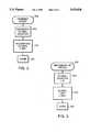
- FIG. 2is a flow chart showing the steps of a method for maintaining a global counter and a global limit register responsive to data transmission;
- FIG. 3is a flow chart showing steps of a method for maintaining a global counter and a global limit register at the beginning of an epoch;
- FIG. 4is a flow chart showing steps of a method for maintaining a connection counter during transmission
- FIG. 5is a flow chart showing steps of a method for maintaining a connection counter at the beginning of an epoch
- FIG. 6is a detailed logic diagram of the flow control logic shown in FIG. 1;
- FIG. 7is a logic drawing of an alternative embodiment of the flow control apparatus.
- FIG. 8is a graph showing values of the global limit register in an embodiment using step-wise global limit setting.
- a logical connection between a first node and a second nodeis known as a virtual circuit.
- a route from the first node to the second nodeis chosen as part of the connection setup. That route is used for all subsequent traffic flowing over the connection.
- each node along the routemaintains a virtual circuit table with one entry per virtual circuit.
- each message travelling over a given virtual circuitcontains a field or fields identifying the virtual circuit over which the cell is transmitted. Further, the field or fields in the message typically identify an entry in a virtual circuit table within each node along the route.
- a virtual circuit table entrycontains control bits for the associated virtual circuit, for example a control bit that enables and disables transmission on the associated virtual circuit.
- Virtual circuitsare also used to reserve receive buffers in the first node and the second node, and within intermediate nodes between the first node and second node. In this way a virtual circuit is used to define a predetermined level of throughput between the first node and the second node. The predetermined level allows the second node to reserve sufficient receive buffers to store data transmitted from the first node such that data transmitted from the first node is not discarded for lack of receive buffers.
- a flow control systemmust ensure that no more data is transmitted than can be stored in the receive buffers in the receiving node.
- rate based flow control systemsthe rate of transmission from the transmitting node to the receiving node is controlled such that the rate does not cause the receiving node to run out of receive buffers to store messages transmitted from the transmitting node.
- a rate based flow control systemwill minimize or eliminate the number of messages discarded by the receiving node due to lack of available receive buffers.
- Data Transmission Unit(DTU) is used herein to refer to a unit length of data transmitted from a transmitting network node to a receiving network node.
- the specific size of a DTUis implementation specific.
- Each message transmitted between a transmitting network node and a receiving network nodehas a size equal to some number of DTUs.
- the term "cell”is used herein to refer to a unit of data having size equal to one DTU.
- An example of a system using fixed sized messages known as cellsis Asynchronous Transfer Mode (ATM).
- ATMAsynchronous Transfer Mode
- the example embodiments hereinare described in terms of cells. It will be evident to one skilled in the art that the principles of the invention also apply to systems using variable length messages, such as packets or frames, to exchange data between network nodes.
- FIG. 1is a logic drawing of the elements in a flow control apparatus.
- a first network node 5is shown containing a transceiver circuit 40, a flow control circuit 7, and a memory 25.
- the transceiver circuit 40is shown coupled with a network 50 via a communications link 45.
- the transceiver circuit 40is further coupled with the flow control circuit 7, and the memory 25.
- the flow control circuit 7contains a set of one or more connection counters 10, including connection counters 10a, 10b, 10c . . . 10n, where n is the maximum possible number of potential virtual circuits with a second node 55, as well as a global limit register 20, a global counter 15, an epoch timer 32, and a flow control logic 30.
- the connection counters 10, as well as the global limit register 20, the epoch timer 32, and the global counter 15,are coupled with the flow control logic 30.
- the flow control circuit 7further contains a virtual circuit table 29, having an entry for every possible virtual circuit between the first network node 5 and other network nodes.
- connection counters 10, global counter 15, and global limit register 20are contained in the flow control circuit 7.
- some or all of connection counters 10, global counter 15, and global limit register 20may be memory locations allocated by a program running on a node processor.
- the network 50could be a local area network (LAN), a wide area network (WAN), a metropolitan area network (MAN), or other type of communications system.
- the second network node 55is coupled with the network 50, via a link 46.
- the second network node 55includes a transceiver 56 coupled with the network 50.
- a memory 57 in the second network node 55includes a set of one or more receive buffers 59, for storing cells or messages received from the first network node 5.
- the flow control circuitreserves bandwidth sufficient to support a data rate of Min/T from the first network node 5 to the second network node 55 over a given VC.
- the remaining bandwidthis a shared bandwidth pool maintained by the flow control circuit, for transmitting data over any VC between the first network node 5 and the second network node 55.
- the memory 25 in the first network node 5further contains a set of one or more data messages 27, the data messages 27 containing data to be transmitted by the first network node 5 to the second network node 55.
- the flow control circuit 7, and the transceiver circuit 40 in the first network node 5may be implemented using standard integrated circuit devices.
- a further discussion of such devicesis given in many textbooks, for example "An Engineering Approach to Digital Design", by William I. Fletcher, published by Prentice-Hall, Englewood Cliffs, N.J., 1980, at pages 440 through 515, all disclosures of which are herein included by reference.
- ASICsApplication Specific Integrated Circuits
- PLDsProgrammable Logic Devices
- first network node 5 and second network node 55establish a number N virtual circuits with each other.
- the operation of the elements shown in FIG. 1guarantees bandwidth sufficient to support a minimum transmission rate of Min/T for each of the N virtual circuits where T is the duration of the epoch timer 32, and Min is a number of Data Transmission Units.
- the maximum data rate permitted over the communications link 45is equal to MaxRate.
- a shared bandwidth poolequal to MaxRate-(N * Min/T) is shared among the N virtual circuits.
- the number of DTUs that may be transmitted using the shared bandwidth poolis referred to as "CommonPool", and is equal to (MaxRate * T)-(N * Min).
- the operation of the elements shown in FIG. 1guarantees that each virtual circuit is allocated a maximum transmission rate of Max/T, where Max is greater than or equal to Min, and less than or equal to CommonPool.
- the specific value of Maxis based on user traffic requirements.
- first network node 5 and second network node 55For each virtual circuit between first network node 5 and second network node 55, there is an entry in virtual circuit table 29 within the first network node.
- Messages transmitted between the first network node 5 and the second network node 55contain indication of a specific virtual circuit over which they are transmitted, for example a field containing a virtual circuit number indexing entries in the virtual circuit table 29.
- the flow control logic 30sets each connection counter 10 to zero when each virtual circuit is established, and whenever the link between the first network node 5 and the second network node 55 is broken and then subsequently re-established.
- the global counter 15is initialized to 0 when the first virtual circuit is established between the first network node 5 and the second network node 55.
- the flow control logic 30sets each connection counter to zero responsive to the epoch timer 32 indicating that an epoch has completed, where an epoch is equal to a time period of T duration.
- the epoch timer 32has a period equal to T, and begins running responsive to establishment of the first virtual circuit between the first network node 5 and the second network node 55.
- connection counter 10 for a specific virtual circuitis initialized to some number k greater than zero, and subsequently each time period T the flow control logic 30 sets that connection counter 10 equal to k. In this way, the bandwidth allocated for that specific virtual circuit is to be limited relative to other connections.
- the flow control logic 30maintains the global counter 15 as the total number of DTUs transmitted from the first network node 5 to the second network node 55 during the current epoch, responsive to each transmission from first network node 5 over communications link 45 to second network node 55.
- the flow control logic 30also modifies the global limit register 20 responsive to the current value in the global counter 15 after each transmission on communications link 45 from first network node 5 to second network node 55.
- the global counterexceeds an upper threshold value UT, where UT is equal to (MaxRate * T)-(Min * N)
- the flow control logic 30sets the value of the global limit register 20 to Min.
- the flow control logic 30sets the global limit register equal to Max responsive to expiration of the epoch timer 32.
- the first network node 5has one global limit register and one global counter.
- FIG. 2shows the steps performed to maintain the global counter and the global limit register as one of data messages 27, (27a for purposes of example), is transmitted from first network node 5 of FIG. 1.
- the steps of FIG. 2are performed by an example embodiment of the flow control logic 30 shown in FIG. 1.
- data message 27ais transmitted by the first network node 5 to the second network node 55 in step 200.
- the flow control logic 30responds to the transmission in step 200 by incrementing the global counter 15 by the number of DTUs required to transmit data message 27a.
- the data message 27ais a cell, and requires one DTU of bandwidth to be transmitted.
- the global counter 15is therefore incremented by 1.
- the flow control logic 30re-calculates the value of the global limit register 20 responsive to the value of the global counter 15.
- the data message 27ais transmitted from the first network node 5, it is received by the second network node 55.
- the transceiver 56 within the second network node 55receives the data message 27a and writes the data message 27a into a subset of one or more of the receive buffers 59, for example receive buffer 59a.
- FIG. 3shows the steps performed by an example embodiment of the flow control logic 30, within the first network node 5 of FIG. 1, upon expiration of the epoch timer 32, to maintain the global limit register 20 and the global counter 15.
- the global counter 15is set to zero in step 310.
- the value of the global limit register 20is set to Max.
- step 315the processing in response to the expiration of the epoch timer 32 expiration completes in step 320, until the next expiration of the epoch timer 32.
- the epoch timer 32is a free running timer, continuing to run after it expires.
- FIG. 4shows the steps performed to maintain the connection counters 10 when one of data messages 27 is transmitted by the first network node 5. The steps of FIG. 4 are performed by an example embodiment of the flow control logic 30 in the first network node 5 of FIG. 1.
- one of data messages 27(for example 27a) is transmitted over a given virtual circuit between the first network node 5 and the second network node 55 in step 400.
- the connection counter 10 for that virtual circuit(for example connection counter 10a) is incremented in step 410 by the number of DTUs required to transmit the data message 27a. For example, if the data message 27a is a cell, requiring one DTU of bandwidth to transmit, the connection counter 10a is incremented by 1.
- step 415the connection counter 10a is compared with the value of the global limit register 20. If the connection counter 10a is less than the global limit register 20, processing completes for this transmission in step 420. If the connection counter 10a is greater than or equal to the value of the global limit register 20, step 425 is performed. In step 425, the flow control logic 30 stops further transmission on the virtual circuit corresponding to connection counter 10a. Transmission on a virtual circuit can, in an example embodiment, be stopped by setting a Transmission Disable bit in the entry for that virtual circuit in the virtual circuit table 29 of FIG. 1. Following step 425, the process completes for the transmission in step 430.
- FIG. 5shows the steps performed by an example embodiment of the flow control logic 30 shown in FIG. 1 to maintain the connection counters 10 of the first network node 5 in FIG. 1 upon expiration of the epoch timer 32.
- the flow control logicdetects that the epoch timer 32 has expired.
- the flow control logic 30sets all connection counters 10 to zero.
- step 510is next followed by step 515.
- step 515if transmissions for any of the virtual circuits corresponding to connection counters 10 had previously been disabled, transmissions are re-enabled on those virtual circuits.
- step 525the process completes in step 530.
- FIG. 6is a detailed logic diagram of an example embodiment of the flow control logic 30 shown in FIG. 1.
- the flow control logic 30is an ASIC, containing several logic processes.
- FIG. 6shows the flow control logic 30 having a transmission event detecting process 610, coupled with a global counter-incrementing process 620 and a connection counter incrementing process 640.
- the global counter incrementing process 620is coupled with a first comparison process 625, which in turn is coupled with a first global limit setting process 630.
- connection counter incrementing process 640is coupled with a second comparison process 645, which in turn is coupled with a transmission disabling process 650.
- FIG. 6further shows a timer expiration detecting process 660, coupled with a connection counter clearing process 665, which is coupled with a global counter clearing process 670, which in turn is coupled with a global limit setting process 675.
- the transmission event detecting process 610detects the transmission event 600.
- a transmission event 600follows a request by a user in a first network node to send a cell to a second network node over a virtual circuit between the first network node and the second network node. The transmission event is then detected when the transmission of the cell from the first network node occurs.
- the global counter incrementing process 620increments the global counter by the number of DTUs in the transmitted message. If the transmitted message was a cell, then the global counter is incremented by one.
- the first comparison process 625compares the new value of the global counter with Upper Threshold UT. If the first comparison process 625 determines that the value of the global counter is greater than or equal to the upper threshold UT, then first comparison step 625 is followed by global limit setting process 630. If the first comparison process 625 determines that the global counter is not greater than the upper threshold UT, then first comparison process 625 is followed by completion in step 635.
- connection counter incrementing process 640increments the connection counter corresponding with the virtual circuit over which the transmission was made by the number of DTUs required to perform the transmission. For example, if a cell was transmitted, the connection counter corresponding with the virtual circuit over which the cell was transmitted is incremented by one.
- connection counter incrementing process 640incrementing the connection counter for the virtual circuit of the transmission event 600
- second comparison process 645the incremented connection counter is compared with the value of the global limit register for the second network node. If the incremented connection counter is greater than or equal to the global limit register, then the transmission stopping process 630 stops further transmissions on that virtual circuit. In an example embodiment, the current transmission is also stopped. In an alternative example embodiment, the current transmission is allowed to complete, while subsequent transmissions on that virtual circuit are disabled for the remainder of the current epoch. If the incremented connection counter is less than the global limit register, then the transmission is allowed to complete, and the cell transmitted from the first network node to the second network node.
- the logic processes 620, 625, and 630may execute in parallel with the logic processes 640, 645, and 650, subsequent to the transmission event detecting process 610 detecting the transmission event 600.
- the timer expiration detecting process 660detects the expiration of the epoch timer 655. Subsequent to the timer expiration detecting process 660 detecting the expiration of the epoch timer 655, the connection counter clearing process 665 clears all the connection counters. After the connection counter clearing process 665 clears all the connection counters, the global counter clearing process 670 sets the global counter to zero. Following the global counter clearing process 670 setting the global counter to zero, the global limit setting process 675 sets the global limit to Max. After the global limit setting process 675 completes, those processes 660, 665, 670 and 675 which are responsive to detection of the expiration of the epoch timer 655 reach completion. It will be evident to one skilled in the art that the order of processes 660, 665, 670 and 675 shown in FIG. 6 is given for purposes of example, and other orders are possible dependent on the constraints of specific implementations.
- FIG. 7is a logic drawing of the elements in a flow control apparatus for a communications link within a network node 1005.
- a plurality of connection counters 1010consisting of connection counters 1010a, 1010b, 1010c . . . 1010n, are shown coupled with a global limit register 1020.
- the number of connection counters nis the maximum possible number of virtual circuits on the communications link.
- connection counters 1010, global counter 1015, and global limit register 1020are shown contained in a memory 1025.
- some or all of connection counters 1010, global counter 1015, and global limit register 1020could be implemented as hardware registers.
- a node processor 1035coupled with the memory 1025
- an epoch timer 1032coupled with the node processor 1035
- a program 1030 running on the node processor 1035and a transceiver circuit 1040, coupled with the node processor and a network 1050.
- the network 1050could be a local area network (LAN), a wide area network (WAN), a metropolitan area network (MAN), or other type of communications system.
- LANlocal area network
- WANwide area network
- MANmetropolitan area network
- a second network node 1055is also shown coupled with the LAN 1050.
- the second network node 1055includes a transceiver 1056 coupled with the network 1050 and also coupled with a memory 1057.
- the memory 1057 in the second network node 1055includes a set of one or more receive buffers 1059, for storing data received from the network 1050.
- alternative embodiments to the example embodiment in FIG. 7include implementations based on other currently available technologies, for example an application specific integrated circuit (ASIC) to perform some or all of the functions performed by the program 1030 running on the node processor 1035.
- ASICapplication specific integrated circuit
- the selection of whether to have the functions performed by the node processor 1035, ASIC, or other type of currently available technologyis based on implementation specific trade-offs, for example taking into account the expense of using an ASIC as balanced against the generally faster processing speeds achievable with an ASIC.
- the memory 1025further contains a virtual circuit table 1029, having an entry for each virtual circuit between the network node 5 and other network nodes on the network 1050, and a set of one or more data messages 1027, containing data to be transmitted by the network node 1005 to other nodes on the network 1050.
- the program 1030executes on the node processor 1035.
- the functions performed by the program 1030are the functions performed by the flow control logic 30 shown in the embodiment of FIG. 1.
- FIG. 8shows the values of the global limit register, as a function of the global counter, during operation of the embodiment shown in FIGS. 7 in a transmitting first node.
- the horizontal axis 1152 of the graph in FIG. 8represents the value of the global counter.
- the vertical axis 1154represents values of the global limit register.
- the dotted line 1100shows the values of the global limit register in the first node as a function of the values of the global counter in the first node.
- the global limit register in the first nodeis set to Min when the value of the global counter in the first node exceeds an upper threshold value UT.
- Max and Minare chosen on a per connection basis.
- equation for CommonPoolis: ##EQU2## where Min(i) is the value of Min for connection i.
- the above example embodimentalso decrements the global limit register from Max to Min in a single step.
- the global limit registertransitions between Max and Min by multiple discrete levels.
- the value of the global limit registeris set based on a decreasing linear function of the global counter, such that the value of the global limit register is decremented from Max to Min as the global counter increases from a predetermined value to UT.
Landscapes
- Engineering & Computer Science (AREA)
- Computer Networks & Wireless Communication (AREA)
- Signal Processing (AREA)
- Data Exchanges In Wide-Area Networks (AREA)
Abstract
Description
(MaxRate * T)-(Min * N),
Claims (6)
Priority Applications (1)
| Application Number | Priority Date | Filing Date | Title |
|---|---|---|---|
| US08/268,076US5455826A (en) | 1994-06-28 | 1994-06-28 | Method and apparatus for rate based flow control |
Applications Claiming Priority (1)
| Application Number | Priority Date | Filing Date | Title |
|---|---|---|---|
| US08/268,076US5455826A (en) | 1994-06-28 | 1994-06-28 | Method and apparatus for rate based flow control |
Publications (1)
| Publication Number | Publication Date |
|---|---|
| US5455826Atrue US5455826A (en) | 1995-10-03 |
Family
ID=23021358
Family Applications (1)
| Application Number | Title | Priority Date | Filing Date |
|---|---|---|---|
| US08/268,076Expired - LifetimeUS5455826A (en) | 1994-06-28 | 1994-06-28 | Method and apparatus for rate based flow control |
Country Status (1)
| Country | Link |
|---|---|
| US (1) | US5455826A (en) |
Cited By (67)
| Publication number | Priority date | Publication date | Assignee | Title |
|---|---|---|---|---|
| US5561663A (en)* | 1994-12-30 | 1996-10-01 | Stratacom, Inc. | Method and apparatus for performing communication rate control using geometric weighted groups |
| WO1997004563A1 (en)* | 1995-07-19 | 1997-02-06 | Fujitsu Network Communications, Inc. | Joint flow control mechanism in a telecommunications network |
| US5734825A (en)* | 1994-07-18 | 1998-03-31 | Digital Equipment Corporation | Traffic control system having distributed rate calculation and link by link flow control |
| US5748630A (en)* | 1996-05-09 | 1998-05-05 | Maker Communications, Inc. | Asynchronous transfer mode cell processing system with load multiple instruction and memory write-back |
| US5748631A (en)* | 1996-05-09 | 1998-05-05 | Maker Communications, Inc. | Asynchronous transfer mode cell processing system with multiple cell source multiplexing |
| US5754787A (en)* | 1994-12-23 | 1998-05-19 | Intel Corporation | System for electronically publishing objects with header specifying minimum and maximum required transport delivery rates and threshold being amount publisher is willing to pay |
| US5787071A (en)* | 1994-11-08 | 1998-07-28 | International Business Machines | Hop-by-hop flow control in an ATM network |
| US5794025A (en)* | 1996-05-09 | 1998-08-11 | Maker Communications, Inc. | Method and device for performing modulo-based arithmetic operations in an asynchronous transfer mode cell processing system |
| US5854898A (en)* | 1995-02-24 | 1998-12-29 | Apple Computer, Inc. | System for automatically adding additional data stream to existing media connection between two end points upon exchange of notifying and confirmation messages therebetween |
| US5860148A (en)* | 1996-05-09 | 1999-01-12 | Maker Communications, Inc. | Asynchronous transfer mode cell processing system with cell buffer space gathering |
| GB2327317A (en)* | 1997-07-11 | 1999-01-20 | Ericsson Telefon Ab L M | Access control and resource reservation in a communications network |
| US5864536A (en)* | 1995-08-28 | 1999-01-26 | Siemens Aktiengesellschaft | Method and apparatus for adapting a transmission bit rate of a data multiplexer operating according to an asynchronous transfer mode |
| US5913040A (en)* | 1995-08-22 | 1999-06-15 | Backweb Ltd. | Method and apparatus for transmitting and displaying information between a remote network and a local computer |
| US5940377A (en)* | 1995-12-21 | 1999-08-17 | Kabushiki Kaisha Toshiba | Asynchronous transfer mode switch including cell counter verification circuitry |
| US5974029A (en)* | 1996-10-31 | 1999-10-26 | Inverness System Ltd. | Method for limiting the transmission of data generated by a data source |
| US5973724A (en)* | 1995-02-24 | 1999-10-26 | Apple Computer, Inc. | Merging multiple teleconferences |
| US5991867A (en)* | 1996-09-12 | 1999-11-23 | Efficient Networks, Inc. | Transmit scheduler for an asynchronous transfer mode network and method of operation |
| US5996013A (en)* | 1997-04-30 | 1999-11-30 | International Business Machines Corporation | Method and apparatus for resource allocation with guarantees |
| US6026075A (en)* | 1997-02-25 | 2000-02-15 | International Business Machines Corporation | Flow control mechanism |
| US6038216A (en)* | 1996-11-01 | 2000-03-14 | Packeteer, Inc. | Method for explicit data rate control in a packet communication environment without data rate supervision |
| US6075772A (en)* | 1997-08-29 | 2000-06-13 | International Business Machines Corporation | Methods, systems and computer program products for controlling data flow for guaranteed bandwidth connections on a per connection basis |
| US6084881A (en)* | 1997-05-22 | 2000-07-04 | Efficient Networks, Inc. | Multiple mode xDSL interface |
| US6085250A (en)* | 1997-03-20 | 2000-07-04 | Efficient Networks, Inc. | Method and system for using layered networking application program interfaces (APIs) using a native asynchronous transfer mode (ATM) API |
| US6084880A (en)* | 1994-09-12 | 2000-07-04 | Efficient Networks, Inc. | Asynchronous transfer mode adapter for desktop applications |
| US6122289A (en)* | 1997-08-29 | 2000-09-19 | International Business Machines Corporation | Methods, systems and computer program products for controlling data flow through a communications adapter |
| US6128303A (en)* | 1996-05-09 | 2000-10-03 | Maker Communications, Inc. | Asynchronous transfer mode cell processing system with scoreboard scheduling |
| US6134217A (en)* | 1996-04-15 | 2000-10-17 | The Regents Of The University Of California | Traffic scheduling system and method for packet-switched networks with fairness and low latency |
| US6147970A (en)* | 1997-09-30 | 2000-11-14 | Gte Internetworking Incorporated | Quality of service management for aggregated flows in a network system |
| US6185619B1 (en) | 1996-12-09 | 2001-02-06 | Genuity Inc. | Method and apparatus for balancing the process load on network servers according to network and serve based policies |
| EP1133202A1 (en)* | 2000-03-07 | 2001-09-12 | Lucent Technologies Inc. | Radio telecommunications system with improved use of air interface (II) |
| US20020002618A1 (en)* | 2000-04-17 | 2002-01-03 | Mark Vange | System and method for providing last-mile data prioritization |
| US6452905B1 (en)* | 1995-03-08 | 2002-09-17 | British Telecommunications Public Limited Company | Broadband switching system |
| US6452903B1 (en) | 2000-05-31 | 2002-09-17 | Fujitsu Network Communications, Inc. | Network switch supporting rate-based and credit-based flow control mechanisms on a link-by-link basis |
| US6466541B1 (en) | 2000-05-31 | 2002-10-15 | Fujitsu Network Communications, Inc. | Cell pacing on a network link employing a rate-based flow control protocol with underlying credit-based flow control mechanisms |
| US6480608B2 (en)* | 1995-11-04 | 2002-11-12 | Marconi Communications Limited | Method for exchanging cryptographic keys in an ATM network using multiple virtual paths or circuits |
| US20030021279A1 (en)* | 1995-03-13 | 2003-01-30 | Kabushiki Kaisha Toshiba | ATM communication system, process migration method in the ATM communication system, and handover processing method |
| US20030109253A1 (en)* | 2000-01-18 | 2003-06-12 | Fenton Shaun Richard | Digital communications system |
| US6590897B1 (en) | 1999-03-08 | 2003-07-08 | Efficient Networks, Inc. | System and method for bridging universal serial bus and asynchronous transfer mode communication links |
| US6594271B1 (en)* | 1999-07-19 | 2003-07-15 | General Instruments Corporation | Implementation of opportunistic data on a statistical multiplexing encoder |
| US6657961B1 (en) | 1998-08-18 | 2003-12-02 | Efficient Networks, Inc. | System and method for enhanced end station to end station data flow control |
| US6661774B1 (en) | 1999-02-16 | 2003-12-09 | Efficient Networks, Inc. | System and method for traffic shaping packet-based signals |
| US20040017804A1 (en)* | 2002-07-19 | 2004-01-29 | Meenaradchagan Vishnu | Arbiter for an input buffered communication switch |
| US20040165530A1 (en)* | 2003-02-25 | 2004-08-26 | Bedekar Anand S. | Flow control in a packet data communication system |
| US6822961B1 (en)* | 1998-10-02 | 2004-11-23 | Nortel Networks Limited | Method and apparatus for reduction of call setup rate in an ATM network |
| US20040246977A1 (en)* | 2001-06-04 | 2004-12-09 | Jason Dove | Backplane bus |
| US20050013247A1 (en)* | 2002-02-12 | 2005-01-20 | Jussi Sipola | Method for controlling data transmission, and data transmission system |
| US20050018668A1 (en)* | 2003-07-24 | 2005-01-27 | Cheriton David R. | Method and apparatus for processing duplicate packets |
| US20050086339A1 (en)* | 1996-07-02 | 2005-04-21 | Microsoft Corporation | Adaptive bandwidth throttling for network services |
| US20060123007A1 (en)* | 2004-12-08 | 2006-06-08 | Aaron Jeffrey A | Methods and systems that selectively resurrect blocked communications between devices |
| US7106696B1 (en)* | 2001-08-31 | 2006-09-12 | Juniper Networks, Inc. | Systems and methods for limiting the rates of data to/from a buffer |
| US7236459B1 (en) | 2002-05-06 | 2007-06-26 | Packeteer, Inc. | Method and apparatus for controlling data transmission volume using explicit rate control and queuing without data rate supervision |
| US20070189283A1 (en)* | 2002-03-06 | 2007-08-16 | Agere Systems Inc. | Characterizing transmission of data segments within a switch fabric using multiple counters for each destination node |
| US7301906B2 (en) | 2001-12-17 | 2007-11-27 | Lsi Corporation | Methods and structures for improved buffer management and dynamic adaption of flow control status in high-speed communication networks |
| US7360159B2 (en) | 1999-07-16 | 2008-04-15 | Qarbon.Com, Inc. | System for creating media presentations of computer software application programs |
| US20080212472A1 (en)* | 2002-03-06 | 2008-09-04 | Agere Systems Inc. | Backpressure mechanism for switching fabric |
| US7869366B1 (en) | 2006-03-28 | 2011-01-11 | Packeteer, Inc. | Application-aware rate control |
| US20140140259A1 (en)* | 2005-07-29 | 2014-05-22 | The Directv Group, Inc. | Method and apparatus for transmitting high bandwidth signals with low bandwidth transponders |
| US20140215562A1 (en)* | 2013-01-30 | 2014-07-31 | Palo Alto Networks, Inc. | Event aggregation in a distributed processor system |
| US9077702B2 (en) | 2013-01-30 | 2015-07-07 | Palo Alto Networks, Inc. | Flow ownership assignment in a distributed processor system |
| US9240975B2 (en) | 2013-01-30 | 2016-01-19 | Palo Alto Networks, Inc. | Security device implementing network flow prediction |
| US20160283540A1 (en)* | 2015-03-27 | 2016-09-29 | International Business Machines Corporation | Concurrent reads and inserts into a data structure without latching or waiting by readers |
| US9922064B2 (en) | 2015-03-20 | 2018-03-20 | International Business Machines Corporation | Parallel build of non-partitioned join hash tables and non-enforced N:1 join hash tables |
| US9979464B1 (en) | 2005-07-29 | 2018-05-22 | The Directv Group, Inc. | Combining transponder bandwidths for source and forward error correction encoding efficiency |
| US10303791B2 (en) | 2015-03-20 | 2019-05-28 | International Business Machines Corporation | Efficient join on dynamically compressed inner for improved fit into cache hierarchy |
| US10489403B2 (en) | 2014-10-08 | 2019-11-26 | International Business Machines Corporation | Embracing and exploiting data skew during a join or groupby |
| US10650011B2 (en) | 2015-03-20 | 2020-05-12 | International Business Machines Corporation | Efficient performance of insert and point query operations in a column store |
| US10831736B2 (en) | 2015-03-27 | 2020-11-10 | International Business Machines Corporation | Fast multi-tier indexing supporting dynamic update |
Citations (8)
| Publication number | Priority date | Publication date | Assignee | Title |
|---|---|---|---|---|
| US4475192A (en)* | 1982-02-16 | 1984-10-02 | At&T Bell Laboratories | Data packet flow control scheme for switching networks |
| US4769811A (en)* | 1986-12-31 | 1988-09-06 | American Telephone And Telegraph Company, At&T Bell Laboratories | Packet switching system arranged for congestion control |
| US4849968A (en)* | 1985-09-06 | 1989-07-18 | Washington University | Buffer management system |
| US5199027A (en)* | 1989-03-14 | 1993-03-30 | Alcatel N.V. | Communication switching system |
| US5278825A (en)* | 1991-02-01 | 1994-01-11 | Siemens Aktiengesellschaft | Method for monitoring and smoothing data streams that are transmitted asynchronously |
| US5285446A (en)* | 1990-11-27 | 1994-02-08 | Nec Corporation | Cell flow control unit and method for asynchronous transfer mode switching networks |
| US5289462A (en)* | 1992-08-19 | 1994-02-22 | International Business Machines Corp. | Traffic management in packet communications networks |
| US5335224A (en)* | 1992-06-30 | 1994-08-02 | At&T Bell Laboratories | Service guarantees/congestion control in high speed networks |
- 1994
- 1994-06-28USUS08/268,076patent/US5455826A/ennot_activeExpired - Lifetime
Patent Citations (8)
| Publication number | Priority date | Publication date | Assignee | Title |
|---|---|---|---|---|
| US4475192A (en)* | 1982-02-16 | 1984-10-02 | At&T Bell Laboratories | Data packet flow control scheme for switching networks |
| US4849968A (en)* | 1985-09-06 | 1989-07-18 | Washington University | Buffer management system |
| US4769811A (en)* | 1986-12-31 | 1988-09-06 | American Telephone And Telegraph Company, At&T Bell Laboratories | Packet switching system arranged for congestion control |
| US5199027A (en)* | 1989-03-14 | 1993-03-30 | Alcatel N.V. | Communication switching system |
| US5285446A (en)* | 1990-11-27 | 1994-02-08 | Nec Corporation | Cell flow control unit and method for asynchronous transfer mode switching networks |
| US5278825A (en)* | 1991-02-01 | 1994-01-11 | Siemens Aktiengesellschaft | Method for monitoring and smoothing data streams that are transmitted asynchronously |
| US5335224A (en)* | 1992-06-30 | 1994-08-02 | At&T Bell Laboratories | Service guarantees/congestion control in high speed networks |
| US5289462A (en)* | 1992-08-19 | 1994-02-22 | International Business Machines Corp. | Traffic management in packet communications networks |
Non-Patent Citations (10)
| Title |
|---|
| 1980, Fletcher, W. I., published by Prentice Hall, Englewood Cliffs, N.J., An Engineering Approach to Digital Design, pp. 440 515.* |
| 1980, Fletcher, W. I., published by Prentice-Hall, Englewood Cliffs, N.J., An Engineering Approach to Digital Design, pp. 440-515. |
| 1988, Tannenbaum, A. S., Computer Networks, 2nd Edition, pp. 280 284.* |
| 1988, Tannenbaum, A. S., Computer Networks, 2nd Edition, pp. 280-284. |
| 1989, DiGiacomo, J., published by McGraw Hill, N.Y., VLSI Handbook, pp. 17.3 22.13.* |
| 1989, DiGiacomo, J., published by McGraw-Hill, N.Y., VLSI Handbook, pp. 17.3-22.13. |
| Jun. 21, 1993, Kung, H. T., Chapman, A., The FCVC ( Flow Controlled Virtual Channels ) Proposal for ATM Networks (Draft).* |
| Jun. 21, 1993, Kung, H. T., Chapman, A., The FCVC (Flow Controlled Virtual Channels) Proposal for ATM Networks (Draft). |
| Oct. 1991, Schroeder, M. D., Birrell, A. D., Burrows, M., Murray H., Needham, R. M., Rodeheffer, T. L., Satterthwaite, E. H., vol. 9, No. 8, Autonet: A High Speed, Self Configuring Local Area Network Using Point to Point Links.* |
| Oct. 1991, Schroeder, M. D., Birrell, A. D., Burrows, M., Murray H., Needham, R. M., Rodeheffer, T. L., Satterthwaite, E. H., vol. 9, No. 8, Autonet: A High-Speed, Self-Configuring Local Area Network Using Point-to-Point Links. |
Cited By (130)
| Publication number | Priority date | Publication date | Assignee | Title |
|---|---|---|---|---|
| US5968128A (en)* | 1994-07-18 | 1999-10-19 | Cabletron Systems, Inc. | Traffic control system having distributed rate calculation and link by link flow control |
| US5734825A (en)* | 1994-07-18 | 1998-03-31 | Digital Equipment Corporation | Traffic control system having distributed rate calculation and link by link flow control |
| US6615271B1 (en) | 1994-07-18 | 2003-09-02 | Enterasys Networks, Inc. | Traffic control system having distributed rate calculation and link flow control |
| US6084880A (en)* | 1994-09-12 | 2000-07-04 | Efficient Networks, Inc. | Asynchronous transfer mode adapter for desktop applications |
| US5787071A (en)* | 1994-11-08 | 1998-07-28 | International Business Machines | Hop-by-hop flow control in an ATM network |
| US5754787A (en)* | 1994-12-23 | 1998-05-19 | Intel Corporation | System for electronically publishing objects with header specifying minimum and maximum required transport delivery rates and threshold being amount publisher is willing to pay |
| US5561663A (en)* | 1994-12-30 | 1996-10-01 | Stratacom, Inc. | Method and apparatus for performing communication rate control using geometric weighted groups |
| US5973724A (en)* | 1995-02-24 | 1999-10-26 | Apple Computer, Inc. | Merging multiple teleconferences |
| USRE42442E1 (en) | 1995-02-24 | 2011-06-07 | Apple Inc. | System for terminating multicast channel and data broadcast when at least two second endpoints do not transmit positive acknowledgement message to first endpoint |
| USRE44395E1 (en) | 1995-02-24 | 2013-07-23 | Apple Inc. | System for terminating multicast channel and data broadcast when at least two second endpoints do not transmit positive acknowledgement message to first endpoint |
| USRE44306E1 (en) | 1995-02-24 | 2013-06-18 | Apple Inc. | System for terminating multicast channel and data broadcast when at least two second endpoints do not transmit positive acknowledgement message to first endpoint |
| USRE44441E1 (en) | 1995-02-24 | 2013-08-13 | Apple Inc. | System for terminating multicast channel and data broadcast when at least two second endpoints do not transmit positive acknowledgment message to first endpoint |
| US5854898A (en)* | 1995-02-24 | 1998-12-29 | Apple Computer, Inc. | System for automatically adding additional data stream to existing media connection between two end points upon exchange of notifying and confirmation messages therebetween |
| USRE40704E1 (en) | 1995-02-24 | 2009-04-28 | Apple Inc. | System for terminating multicast channel and data broadcast when at least two second endpoints do not transmit positive acknowledgement message to first endpoint |
| US5999977A (en)* | 1995-02-24 | 1999-12-07 | Apple Computer, Inc. | System for terminating multicast channel and data broadcast when at least two second endpoints do not transmit positive acknowledgment message to first endpont |
| US6452905B1 (en)* | 1995-03-08 | 2002-09-17 | British Telecommunications Public Limited Company | Broadband switching system |
| US6553014B1 (en) | 1995-03-13 | 2003-04-22 | Kabushiki Kaisha Toshiba | ATM communication system, process migration method in the ATM communication system, and handover processing method |
| US20030035391A1 (en)* | 1995-03-13 | 2003-02-20 | Kabushiki Kaisha Toshiba | ATM communication system, process migration method in the ATM communication system, and handover processing method |
| US20030021279A1 (en)* | 1995-03-13 | 2003-01-30 | Kabushiki Kaisha Toshiba | ATM communication system, process migration method in the ATM communication system, and handover processing method |
| US6925084B2 (en) | 1995-03-13 | 2005-08-02 | Kabushiki Kaisha Toshiba | ATM communication system, process migration method in the ATM communication system, and handover processing method |
| US7272143B2 (en) | 1995-03-13 | 2007-09-18 | Kabushiki Kaisha Toshiba | ATM communication system, process migration method in the ATM communication system, and handover processing method |
| WO1997004563A1 (en)* | 1995-07-19 | 1997-02-06 | Fujitsu Network Communications, Inc. | Joint flow control mechanism in a telecommunications network |
| US5913040A (en)* | 1995-08-22 | 1999-06-15 | Backweb Ltd. | Method and apparatus for transmitting and displaying information between a remote network and a local computer |
| US6317789B1 (en) | 1995-08-22 | 2001-11-13 | Backweb, Ltd. | Method and apparatus for transmitting and displaying information between a remote network and a local computer |
| US5864536A (en)* | 1995-08-28 | 1999-01-26 | Siemens Aktiengesellschaft | Method and apparatus for adapting a transmission bit rate of a data multiplexer operating according to an asynchronous transfer mode |
| US6480608B2 (en)* | 1995-11-04 | 2002-11-12 | Marconi Communications Limited | Method for exchanging cryptographic keys in an ATM network using multiple virtual paths or circuits |
| US5940377A (en)* | 1995-12-21 | 1999-08-17 | Kabushiki Kaisha Toshiba | Asynchronous transfer mode switch including cell counter verification circuitry |
| US6134217A (en)* | 1996-04-15 | 2000-10-17 | The Regents Of The University Of California | Traffic scheduling system and method for packet-switched networks with fairness and low latency |
| US5748630A (en)* | 1996-05-09 | 1998-05-05 | Maker Communications, Inc. | Asynchronous transfer mode cell processing system with load multiple instruction and memory write-back |
| US6128303A (en)* | 1996-05-09 | 2000-10-03 | Maker Communications, Inc. | Asynchronous transfer mode cell processing system with scoreboard scheduling |
| US5748631A (en)* | 1996-05-09 | 1998-05-05 | Maker Communications, Inc. | Asynchronous transfer mode cell processing system with multiple cell source multiplexing |
| US6359891B1 (en) | 1996-05-09 | 2002-03-19 | Conexant Systems, Inc. | Asynchronous transfer mode cell processing system with scoreboard scheduling |
| US5794025A (en)* | 1996-05-09 | 1998-08-11 | Maker Communications, Inc. | Method and device for performing modulo-based arithmetic operations in an asynchronous transfer mode cell processing system |
| US5860148A (en)* | 1996-05-09 | 1999-01-12 | Maker Communications, Inc. | Asynchronous transfer mode cell processing system with cell buffer space gathering |
| US7403476B2 (en) | 1996-07-02 | 2008-07-22 | Microsoft Corporation | Adaptive bandwidth throttling for network services |
| US7680035B2 (en) | 1996-07-02 | 2010-03-16 | Microsoft Corporation | Adaptive bandwidth throttling for network services |
| US20050086339A1 (en)* | 1996-07-02 | 2005-04-21 | Microsoft Corporation | Adaptive bandwidth throttling for network services |
| US20050111489A1 (en)* | 1996-07-02 | 2005-05-26 | Microsoft Corporation | Adaptive bandwidth throttling for network services |
| US7417992B2 (en) | 1996-07-02 | 2008-08-26 | Microsoft Corporation | Adaptive bandwidth throttling for network services |
| US20050243862A1 (en)* | 1996-07-02 | 2005-11-03 | Microsoft Corporation | Adaptive bandwidth throttling for network services |
| US7400633B2 (en) | 1996-07-02 | 2008-07-15 | Microsoft Corporation | Adaptive bandwidth throttling for network services |
| US7079546B2 (en)* | 1996-07-02 | 2006-07-18 | Microsoft Corporation | Adaptive bandwidth throttling for network services |
| US7400632B2 (en) | 1996-07-02 | 2008-07-15 | Microsoft Corporation | Adaptive bandwidth throttling for network services |
| US20060233108A1 (en)* | 1996-07-02 | 2006-10-19 | Microsoft Corporation | Adaptive Bandwidth Throttling for Network Services |
| US5991867A (en)* | 1996-09-12 | 1999-11-23 | Efficient Networks, Inc. | Transmit scheduler for an asynchronous transfer mode network and method of operation |
| US5974029A (en)* | 1996-10-31 | 1999-10-26 | Inverness System Ltd. | Method for limiting the transmission of data generated by a data source |
| US20040174886A1 (en)* | 1996-11-01 | 2004-09-09 | Packer Robert L. | Method for explicit data rate control in a packet communication environment without data rate supervision |
| US6038216A (en)* | 1996-11-01 | 2000-03-14 | Packeteer, Inc. | Method for explicit data rate control in a packet communication environment without data rate supervision |
| US6741563B2 (en) | 1996-11-01 | 2004-05-25 | Packeteer, Inc. | Method for explicit data rate control in a packet communication environment without data rate supervision |
| US6298041B1 (en) | 1996-11-01 | 2001-10-02 | Packeteer, Inc. | Method for explicit data rate control in a packet communication environment without data rate supervision |
| US6928052B2 (en) | 1996-11-01 | 2005-08-09 | Packeteer, Inc. | Method for explicit data rate control in a packet communication environment without data rate supervision |
| US6185619B1 (en) | 1996-12-09 | 2001-02-06 | Genuity Inc. | Method and apparatus for balancing the process load on network servers according to network and serve based policies |
| US8683075B1 (en) | 1996-12-09 | 2014-03-25 | Verizon Corporate Services Group Inc. | Distributed computing system and method for distributing user requests to replicated network servers |
| US6026075A (en)* | 1997-02-25 | 2000-02-15 | International Business Machines Corporation | Flow control mechanism |
| US7002911B1 (en) | 1997-02-25 | 2006-02-21 | International Business Machines Corporation | Flow control mechanism |
| US6085250A (en)* | 1997-03-20 | 2000-07-04 | Efficient Networks, Inc. | Method and system for using layered networking application program interfaces (APIs) using a native asynchronous transfer mode (ATM) API |
| US5996013A (en)* | 1997-04-30 | 1999-11-30 | International Business Machines Corporation | Method and apparatus for resource allocation with guarantees |
| US6084881A (en)* | 1997-05-22 | 2000-07-04 | Efficient Networks, Inc. | Multiple mode xDSL interface |
| GB2327317B (en)* | 1997-07-11 | 2002-02-13 | Ericsson Telefon Ab L M | Access control and resourse reservation in a communications network |
| GB2327317A (en)* | 1997-07-11 | 1999-01-20 | Ericsson Telefon Ab L M | Access control and resource reservation in a communications network |
| US6205484B1 (en) | 1997-07-11 | 2001-03-20 | Telefonaktiebolaget Lm Ericsson | Controlling access to resources in a connectionless network using a ticket message containing reserved network resource allocation information |
| US6122289A (en)* | 1997-08-29 | 2000-09-19 | International Business Machines Corporation | Methods, systems and computer program products for controlling data flow through a communications adapter |
| US6075772A (en)* | 1997-08-29 | 2000-06-13 | International Business Machines Corporation | Methods, systems and computer program products for controlling data flow for guaranteed bandwidth connections on a per connection basis |
| US6147970A (en)* | 1997-09-30 | 2000-11-14 | Gte Internetworking Incorporated | Quality of service management for aggregated flows in a network system |
| US6657961B1 (en) | 1998-08-18 | 2003-12-02 | Efficient Networks, Inc. | System and method for enhanced end station to end station data flow control |
| US6822961B1 (en)* | 1998-10-02 | 2004-11-23 | Nortel Networks Limited | Method and apparatus for reduction of call setup rate in an ATM network |
| US6661774B1 (en) | 1999-02-16 | 2003-12-09 | Efficient Networks, Inc. | System and method for traffic shaping packet-based signals |
| US6590897B1 (en) | 1999-03-08 | 2003-07-08 | Efficient Networks, Inc. | System and method for bridging universal serial bus and asynchronous transfer mode communication links |
| US7360159B2 (en) | 1999-07-16 | 2008-04-15 | Qarbon.Com, Inc. | System for creating media presentations of computer software application programs |
| US6594271B1 (en)* | 1999-07-19 | 2003-07-15 | General Instruments Corporation | Implementation of opportunistic data on a statistical multiplexing encoder |
| US20030109253A1 (en)* | 2000-01-18 | 2003-06-12 | Fenton Shaun Richard | Digital communications system |
| US7499707B2 (en)* | 2000-01-18 | 2009-03-03 | Motorola, Inc. | Method and system for communicating using a quiescent period |
| US7113478B2 (en) | 2000-03-07 | 2006-09-26 | Lucent Technologies Inc. | Radio telecommunications system with improved use of air interface (II) |
| EP1133202A1 (en)* | 2000-03-07 | 2001-09-12 | Lucent Technologies Inc. | Radio telecommunications system with improved use of air interface (II) |
| US6990531B2 (en)* | 2000-04-17 | 2006-01-24 | Circadence Corporation | System and method for providing last-mile data prioritization |
| US20020002618A1 (en)* | 2000-04-17 | 2002-01-03 | Mark Vange | System and method for providing last-mile data prioritization |
| US6466541B1 (en) | 2000-05-31 | 2002-10-15 | Fujitsu Network Communications, Inc. | Cell pacing on a network link employing a rate-based flow control protocol with underlying credit-based flow control mechanisms |
| US6452903B1 (en) | 2000-05-31 | 2002-09-17 | Fujitsu Network Communications, Inc. | Network switch supporting rate-based and credit-based flow control mechanisms on a link-by-link basis |
| US20040246977A1 (en)* | 2001-06-04 | 2004-12-09 | Jason Dove | Backplane bus |
| US7630309B1 (en) | 2001-08-31 | 2009-12-08 | Juniper Networks, Inc. | Systems and methods for limiting the rates of data to/from a buffer |
| US7106696B1 (en)* | 2001-08-31 | 2006-09-12 | Juniper Networks, Inc. | Systems and methods for limiting the rates of data to/from a buffer |
| US8014281B1 (en) | 2001-08-31 | 2011-09-06 | Juniper Networks, Inc. | Systems and methods for limiting the rates of data to/from a buffer |
| US7301906B2 (en) | 2001-12-17 | 2007-11-27 | Lsi Corporation | Methods and structures for improved buffer management and dynamic adaption of flow control status in high-speed communication networks |
| US20050013247A1 (en)* | 2002-02-12 | 2005-01-20 | Jussi Sipola | Method for controlling data transmission, and data transmission system |
| US7426185B1 (en) | 2002-03-06 | 2008-09-16 | Agere Systems Inc. | Backpressure mechanism for switching fabric |
| US7480246B2 (en) | 2002-03-06 | 2009-01-20 | Agere Systems Inc. | Characterizing transmission of data segments within a switch fabric using multiple counters for each destination node |
| US7319695B1 (en) | 2002-03-06 | 2008-01-15 | Agere Systems Inc. | Deficit-based striping algorithm |
| US20080212472A1 (en)* | 2002-03-06 | 2008-09-04 | Agere Systems Inc. | Backpressure mechanism for switching fabric |
| US7586909B1 (en) | 2002-03-06 | 2009-09-08 | Agere Systems Inc. | Striping algorithm for switching fabric |
| US7983287B2 (en) | 2002-03-06 | 2011-07-19 | Agere Systems Inc. | Backpressure mechanism for switching fabric |
| US20070189283A1 (en)* | 2002-03-06 | 2007-08-16 | Agere Systems Inc. | Characterizing transmission of data segments within a switch fabric using multiple counters for each destination node |
| US7236459B1 (en) | 2002-05-06 | 2007-06-26 | Packeteer, Inc. | Method and apparatus for controlling data transmission volume using explicit rate control and queuing without data rate supervision |
| US7720085B1 (en) | 2002-05-06 | 2010-05-18 | Packeteer, Inc. | Method and apparatus for controlling transmission flow using explicit rate control and queuing without data rate supervision |
| US6954811B2 (en) | 2002-07-19 | 2005-10-11 | Calix Networks, Inc. | Arbiter for an input buffered communication switch |
| US20040017804A1 (en)* | 2002-07-19 | 2004-01-29 | Meenaradchagan Vishnu | Arbiter for an input buffered communication switch |
| US7047310B2 (en)* | 2003-02-25 | 2006-05-16 | Motorola, Inc. | Flow control in a packet data communication system |
| US20040165530A1 (en)* | 2003-02-25 | 2004-08-26 | Bedekar Anand S. | Flow control in a packet data communication system |
| US8451817B2 (en)* | 2003-07-24 | 2013-05-28 | Cisco Technology, Inc. | Method and apparatus for processing duplicate packets |
| US20050018668A1 (en)* | 2003-07-24 | 2005-01-27 | Cheriton David R. | Method and apparatus for processing duplicate packets |
| US20090031422A1 (en)* | 2004-12-08 | 2009-01-29 | At & T Intellectual Property I, L.P. | Methods and systems that selectively resurrect blocked communications between devices |
| US8336101B2 (en) | 2004-12-08 | 2012-12-18 | Worcester Technologies Llc | Methods and systems that selectively resurrect blocked communications between devices |
| US20100257606A1 (en)* | 2004-12-08 | 2010-10-07 | At&T Intellectual Property I, L.P. | Methods and systems that selectively resurrect blocked communications between devices |
| US7757286B2 (en) | 2004-12-08 | 2010-07-13 | At&T Intellectual Property I, Lp | Methods and systems that selectively resurrect blocked communications between devices |
| US8112805B2 (en) | 2004-12-08 | 2012-02-07 | Worcester Technologies Llc | Methods and systems that selectively resurrect blocked communications between devices |
| US20060123007A1 (en)* | 2004-12-08 | 2006-06-08 | Aaron Jeffrey A | Methods and systems that selectively resurrect blocked communications between devices |
| US8752177B2 (en) | 2004-12-08 | 2014-06-10 | Intellectual Ventures Ii Llc | Methods and systems that selectively resurrect blocked communications between devices |
| US20140140259A1 (en)* | 2005-07-29 | 2014-05-22 | The Directv Group, Inc. | Method and apparatus for transmitting high bandwidth signals with low bandwidth transponders |
| US10080045B2 (en) | 2005-07-29 | 2018-09-18 | The Directv Group, Inc. | Method and apparatus for transmitting high bandwidth signals with low bandwidth transponders |
| US9979464B1 (en) | 2005-07-29 | 2018-05-22 | The Directv Group, Inc. | Combining transponder bandwidths for source and forward error correction encoding efficiency |
| US9525978B2 (en)* | 2005-07-29 | 2016-12-20 | The Directv Group, Inc. | Method and apparatus for transmitting high bandwidth signals with low bandwidth transponders |
| US7869366B1 (en) | 2006-03-28 | 2011-01-11 | Packeteer, Inc. | Application-aware rate control |
| US9467422B2 (en)* | 2013-01-30 | 2016-10-11 | Palo Alto Networks, Inc. | Event aggregation in a distributed processor system |
| US20140215562A1 (en)* | 2013-01-30 | 2014-07-31 | Palo Alto Networks, Inc. | Event aggregation in a distributed processor system |
| US9240975B2 (en) | 2013-01-30 | 2016-01-19 | Palo Alto Networks, Inc. | Security device implementing network flow prediction |
| US20150229610A1 (en)* | 2013-01-30 | 2015-08-13 | Palo Alto Networks, Inc. | Event aggregation in a distributed processor system |
| US9077702B2 (en) | 2013-01-30 | 2015-07-07 | Palo Alto Networks, Inc. | Flow ownership assignment in a distributed processor system |
| US9762538B2 (en) | 2013-01-30 | 2017-09-12 | Palo Alto Networks, Inc. | Flow ownership assignment in a distributed processor system |
| US10050936B2 (en) | 2013-01-30 | 2018-08-14 | Palo Alto Networks, Inc. | Security device implementing network flow prediction |
| US8997223B2 (en)* | 2013-01-30 | 2015-03-31 | Palo Alto Networks, Inc. | Event aggregation in a distributed processor system |
| US10489403B2 (en) | 2014-10-08 | 2019-11-26 | International Business Machines Corporation | Embracing and exploiting data skew during a join or groupby |
| US9922064B2 (en) | 2015-03-20 | 2018-03-20 | International Business Machines Corporation | Parallel build of non-partitioned join hash tables and non-enforced N:1 join hash tables |
| US10303791B2 (en) | 2015-03-20 | 2019-05-28 | International Business Machines Corporation | Efficient join on dynamically compressed inner for improved fit into cache hierarchy |
| US10387397B2 (en) | 2015-03-20 | 2019-08-20 | International Business Machines Corporation | Parallel build of non-partitioned join hash tables and non-enforced n:1 join hash tables |
| US10394783B2 (en) | 2015-03-20 | 2019-08-27 | International Business Machines Corporation | Parallel build of non-partitioned join hash tables and non-enforced N:1 join hash tables |
| US10650011B2 (en) | 2015-03-20 | 2020-05-12 | International Business Machines Corporation | Efficient performance of insert and point query operations in a column store |
| US11061878B2 (en) | 2015-03-20 | 2021-07-13 | International Business Machines Corporation | Parallel build of non-partitioned join hash tables and non-enforced N:1 join hash tables |
| US20160283540A1 (en)* | 2015-03-27 | 2016-09-29 | International Business Machines Corporation | Concurrent reads and inserts into a data structure without latching or waiting by readers |
| US10108653B2 (en)* | 2015-03-27 | 2018-10-23 | International Business Machines Corporation | Concurrent reads and inserts into a data structure without latching or waiting by readers |
| US10831736B2 (en) | 2015-03-27 | 2020-11-10 | International Business Machines Corporation | Fast multi-tier indexing supporting dynamic update |
| US11080260B2 (en) | 2015-03-27 | 2021-08-03 | International Business Machines Corporation | Concurrent reads and inserts into a data structure without latching or waiting by readers |
Similar Documents
| Publication | Publication Date | Title |
|---|---|---|
| US5455826A (en) | Method and apparatus for rate based flow control | |
| US6002667A (en) | Minimum guaranteed cell rate method and apparatus | |
| US5014265A (en) | Method and apparatus for congestion control in a data network | |
| US5448567A (en) | Control architecture for ATM networks | |
| EP0666665B1 (en) | Method and apparatus for dynamically determining and allocating shared resource access quota | |
| EP0398037B1 (en) | Packet network with communication resource allocation and call set up control of higher quality of service | |
| US5734825A (en) | Traffic control system having distributed rate calculation and link by link flow control | |
| US5617409A (en) | Flow control with smooth limit setting for multiple virtual circuits | |
| CA2118471C (en) | Upc-based traffic control framework for atm networks | |
| US4933935A (en) | Communications systems | |
| US6141336A (en) | Traffic scheduling method, system and article of manufacture for a wireless access to an asynchronous transfer mode network | |
| US5001707A (en) | Method of providing reserved bandwidth in a dual bus system | |
| US5193090A (en) | Access protection and priority control in distributed queueing | |
| JPH03188733A (en) | Method of determining window size and method of controlling congestion of data cell | |
| WO2000018108A2 (en) | Method and apparatus implementing a multimedia digital network | |
| CA2130593A1 (en) | Flow control method | |
| JPH09186701A (en) | Optimal bandwidth allocation method and apparatus | |
| JPH11340983A (en) | Scheduling circuit and method | |
| JPH06507289A (en) | A method for allocating resources using forecast-based reservations in integrated service satellite communications networks. | |
| WO1997003549A2 (en) | Prioritized access to shared buffers | |
| US6249819B1 (en) | Method for flow controlling ATM traffic | |
| JP4253062B2 (en) | A frame relay network characterized by a frame relay node comprising a trunk having a controlled overreserved bandwidth | |
| US5390182A (en) | System for synchronous bandwidth allocation in token ring networks | |
| JPH07110010B2 (en) | Information transmission method | |
| JPH04336728A (en) | Ring packet communication network |
Legal Events
| Date | Code | Title | Description |
|---|---|---|---|
| AS | Assignment | Owner name:DIGITAL EQUIPMENT CORPORATION, MASSACHUSETTS Free format text:ASSIGNMENT OF ASSIGNORS INTEREST;ASSIGNORS:OZVEREN, CUNEYT M.;VARGHESE, GEORGE;REEL/FRAME:007065/0887;SIGNING DATES FROM 19940624 TO 19940627 | |
| STCF | Information on status: patent grant | Free format text:PATENTED CASE | |
| AS | Assignment | Owner name:CABLETRON SYSTEMS, INC., NEW HAMPSHIRE Free format text:ASSIGNMENT OF ASSIGNORS INTEREST;ASSIGNOR:DIGITAL EQUIPMENT CORPORATION;REEL/FRAME:009046/0792 Effective date:19980206 | |
| FEPP | Fee payment procedure | Free format text:PAYOR NUMBER ASSIGNED (ORIGINAL EVENT CODE: ASPN); ENTITY STATUS OF PATENT OWNER: LARGE ENTITY | |
| FPAY | Fee payment | Year of fee payment:4 | |
| REMI | Maintenance fee reminder mailed | ||
| AS | Assignment | Owner name:ENTERASYS NETWORKS, INC., NEW HAMPSHIRE Free format text:ASSIGNMENT OF ASSIGNORS INTEREST;ASSIGNOR:CABLETRON SYSTEMS, INC.;REEL/FRAME:011219/0376 Effective date:20000929 | |
| FPAY | Fee payment | Year of fee payment:8 | |
| AS | Assignment | Owner name:OBSIDIAN, LLC, CALIFORNIA Free format text:SECURITY AGREEMENT;ASSIGNOR:ENTERASYS NETWORKS, INC.;REEL/FRAME:017656/0552 Effective date:20060516 Owner name:WELLS FARGO FOOTHILL, INC., CALIFORNIA Free format text:SECURITY AGREEMENT;ASSIGNOR:ENTERASYS NETWORKS, INC.;REEL/FRAME:017656/0552 Effective date:20060516 | |
| FPAY | Fee payment | Year of fee payment:12 | |
| AS | Assignment | Owner name:WELLS FARGO TRUST CORPORATION LIMITED, AS SECURITY Free format text:GRANT OF SECURITY INTEREST IN U.S. PATENTS;ASSIGNOR:ENTERASYS NETWORKS INC.;REEL/FRAME:025339/0875 Effective date:20101109 | |
| AS | Assignment | Owner name:ENTERASYS NETWORKS, INC., MASSACHUSETTS Free format text:RELEASE AND REASSIGNMENT OF PATENTS AND PATENT APPLICATIONS AT REEL/FRAME NO. 17656/0552;ASSIGNORS:WELLS FARGO CAPITAL FINANCE, INC. (FORMERLY KNOWN AS WELLS FARGO FOOTHILL, INC.);ENTERPRISE COMMUNICATIONS FUNDING GMBH, AS SUCCESSOR IN INTEREST TO OBSIDIAN, LLC;REEL/FRAME:025406/0769 Effective date:20101110 | |
| AS | Assignment | Owner name:ENTERASYS NETWORKS INC., MASSACHUSETTS Free format text:TERMINATION AND RELEASE OF SECURITY INTEREST IN PATENTS AT REEL/FRAME NO. 25339/0875;ASSIGNOR:WELLS FARGO TRUST CORPORATION LIMITED;REEL/FRAME:031558/0677 Effective date:20131031 |