US5455499A - Method and apparatus for indicating a battery status - Google Patents
Method and apparatus for indicating a battery statusDownload PDFInfo
- Publication number
- US5455499A US5455499AUS08/051,983US5198393AUS5455499AUS 5455499 AUS5455499 AUS 5455499AUS 5198393 AUS5198393 AUS 5198393AUS 5455499 AUS5455499 AUS 5455499A
- Authority
- US
- United States
- Prior art keywords
- battery
- battery pack
- discharge
- memory
- removable
- Prior art date
- Legal status (The legal status is an assumption and is not a legal conclusion. Google has not performed a legal analysis and makes no representation as to the accuracy of the status listed.)
- Expired - Lifetime
Links
- 238000000034methodMethods0.000titleclaimsdescription9
- 230000003466anti-cipated effectEffects0.000claimsdescription21
- WHXSMMKQMYFTQS-UHFFFAOYSA-NLithiumChemical compound[Li]WHXSMMKQMYFTQS-UHFFFAOYSA-N0.000claimsdescription9
- 230000006870functionEffects0.000claimsdescription9
- 229910052744lithiumInorganic materials0.000claimsdescription9
- 238000005259measurementMethods0.000claimsdescription7
- XEEYBQQBJWHFJM-UHFFFAOYSA-NIronChemical compound[Fe]XEEYBQQBJWHFJM-UHFFFAOYSA-N0.000claimsdescription6
- HBBGRARXTFLTSG-UHFFFAOYSA-NLithium ionChemical compound[Li+]HBBGRARXTFLTSG-UHFFFAOYSA-N0.000claimsdescription3
- -1Nickel Metal HydrideChemical class0.000claimsdescription3
- UCKMPCXJQFINFW-UHFFFAOYSA-NSulphideChemical compound[S-2]UCKMPCXJQFINFW-UHFFFAOYSA-N0.000claimsdescription3
- HCHKCACWOHOZIP-UHFFFAOYSA-NZincChemical compound[Zn]HCHKCACWOHOZIP-UHFFFAOYSA-N0.000claimsdescription3
- 239000002253acidSubstances0.000claimsdescription3
- OJIJEKBXJYRIBZ-UHFFFAOYSA-Ncadmium nickelChemical compound[Ni].[Cd]OJIJEKBXJYRIBZ-UHFFFAOYSA-N0.000claimsdescription3
- 229910052742ironInorganic materials0.000claimsdescription3
- 229910001416lithium ionInorganic materials0.000claimsdescription3
- NUJOXMJBOLGQSY-UHFFFAOYSA-Nmanganese dioxideInorganic materialsO=[Mn]=ONUJOXMJBOLGQSY-UHFFFAOYSA-N0.000claimsdescription3
- 229910052987metal hydrideInorganic materials0.000claimsdescription3
- 229910052759nickelInorganic materials0.000claimsdescription3
- PXHVJJICTQNCMI-UHFFFAOYSA-NnickelSubstances[Ni]PXHVJJICTQNCMI-UHFFFAOYSA-N0.000claimsdescription3
- QELJHCBNGDEXLD-UHFFFAOYSA-Nnickel zincChemical compound[Ni].[Zn]QELJHCBNGDEXLD-UHFFFAOYSA-N0.000claimsdescription3
- 229920000642polymerPolymers0.000claimsdescription3
- 229910052725zincInorganic materials0.000claimsdescription3
- 239000011701zincSubstances0.000claimsdescription3
- 230000000737periodic effectEffects0.000claims2
- 238000004891communicationMethods0.000description12
- 238000010586diagramMethods0.000description6
- 230000008859changeEffects0.000description4
- 230000005611electricityEffects0.000description4
- 230000010354integrationEffects0.000description4
- 238000011022operating instructionMethods0.000description4
- 238000007726management methodMethods0.000description2
- 238000010295mobile communicationMethods0.000description2
- 229910005580NiCdInorganic materials0.000description1
- 230000009471actionEffects0.000description1
- 238000001514detection methodMethods0.000description1
- 239000000446fuelSubstances0.000description1
- 239000004973liquid crystal related substanceSubstances0.000description1
- 238000004519manufacturing processMethods0.000description1
- 230000008520organizationEffects0.000description1
- 230000008569processEffects0.000description1
- 239000004065semiconductorSubstances0.000description1
- 230000003068static effectEffects0.000description1
Images


Classifications
- H—ELECTRICITY
- H02—GENERATION; CONVERSION OR DISTRIBUTION OF ELECTRIC POWER
- H02J—CIRCUIT ARRANGEMENTS OR SYSTEMS FOR SUPPLYING OR DISTRIBUTING ELECTRIC POWER; SYSTEMS FOR STORING ELECTRIC ENERGY
- H02J7/00—Circuit arrangements for charging or depolarising batteries or for supplying loads from batteries
- H02J7/00032—Circuit arrangements for charging or depolarising batteries or for supplying loads from batteries characterised by data exchange
- H02J7/00036—Charger exchanging data with battery
- H—ELECTRICITY
- H02—GENERATION; CONVERSION OR DISTRIBUTION OF ELECTRIC POWER
- H02J—CIRCUIT ARRANGEMENTS OR SYSTEMS FOR SUPPLYING OR DISTRIBUTING ELECTRIC POWER; SYSTEMS FOR STORING ELECTRIC ENERGY
- H02J7/00—Circuit arrangements for charging or depolarising batteries or for supplying loads from batteries
- H02J7/00047—Circuit arrangements for charging or depolarising batteries or for supplying loads from batteries with provisions for charging different types of batteries
- Y—GENERAL TAGGING OF NEW TECHNOLOGICAL DEVELOPMENTS; GENERAL TAGGING OF CROSS-SECTIONAL TECHNOLOGIES SPANNING OVER SEVERAL SECTIONS OF THE IPC; TECHNICAL SUBJECTS COVERED BY FORMER USPC CROSS-REFERENCE ART COLLECTIONS [XRACs] AND DIGESTS
- Y10—TECHNICAL SUBJECTS COVERED BY FORMER USPC
- Y10S—TECHNICAL SUBJECTS COVERED BY FORMER USPC CROSS-REFERENCE ART COLLECTIONS [XRACs] AND DIGESTS
- Y10S320/00—Electricity: battery or capacitor charging or discharging
- Y10S320/18—Indicator or display
- Y10S320/21—State of charge of battery
Definitions
- This inventionrelates to a battery-status-indicating arrangement for use with electronic circuitry.
- Portable battery powered electronic systemsare presently being extensively utilized in a wide range of applications. For example, such systems are being employed in mobile radiotelephone communication sets, portable personal computers, portable camera equipment and the like. In each, the electronic equipment comprising the overall system is controllably put into operation by electric current supplied from an electro-mechanical storage media (battery).
- an electro-mechanical storage mediabattery
- a current industry trendis towards the use of removable and rechargeable batteries or battery packs.
- the system operatorIn order to avoid an equipment failure, however, it is crucial that the system operator be provided an indication of how long the electronic system can further be put into operation by an existing battery.
- batteriestend to discharge over extended periods of non-use, it is crucial that each battery powered electronic system comprise a battery-discharge-indicating arrangement to provide the system operator with an indication of the remaining battery capacity for batteries which have not been in use for a period of time.
- a battery-discharge-indicating apparatus and arrangementfor use with electronic circuitry to provide an operator with a displayed indication of remaining battery capacity.
- a battery-discharge-indicating apparatus and arrangementcomprises method steps and apparatus structure for storing battery identification information, battery capacity information and a time stamp signal within a battery pack memory unit.
- the electronic circuitrycomprises memory for storing battery discharge rate signals representative of an amount of battery discharge exhibited by different battery chemistry types.
- a microprocessorcoupled to the memory means and the timing means and further responsive to signals received from the battery pack, is programmed to determine a battery discharge amount for a time interval when the battery pack is removed from service.
- the microprocessoris also programmed to update the battery capacity information stored in the battery pack memory unit, after determination of the discharge amount, and to cause the updated battery capacity information to be displayed.
- a battery-consumption-indicating apparatus and arrangementcomprises method steps and apparatus structure for storing battery identification information, battery capacity information and a time stamp signal within battery pack memory.
- the electronic circuitrycomprises memory for storing current draw signals representative of an amount of current used by specific circuit modules comprising the electronic circuitry.
- a microprocessorcoupled to the memory means and the timing means and further responsive to signals received from the battery pack, is programmed to determine device consumption amounts during times when the circuit modules comprising the electronic circuitry are put into operation.
- the microprocessoris also programmed to scale said stored current draw signals in order to permit the use of multiple battery pack configurations, based at least partly upon the receipt of said identification information from the battery. Thereafter, the microprocessor operates to update the battery capacity information stored in the battery pack memory, after determination of the consumption amount, and to causes updated battery capacity information to be displayed.
- FIG. 1is a block diagram of a mobile communications device that includes the battery-status-indicating arrangement of the present invention
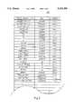
- FIG. 2illustrates a ROM look-up table for use during the a battery-status-indicating arrangement of the present invention
- FIG. 3shows a graphical example for use in describing the operation of the battery-consumption-indicating arrangement and the battery-discharge-indicating arrangement of the present invention
- FIG. 4is a flow chart diagram illustrating the steps performed by the device of FIG. 1 in accordance with the a battery-discharge-indicating arrangement of the present invention.
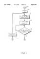
- FIG. 5a flow chart diagram illustrating the steps performed by the device 100 of FIG. 1 in accordance with the a battery-consumption-indicating arrangement of the present invention.
- the present inventionhas application for use within the field of consumer electronics. It is particularly suited for use with portable electronic systems which utilize removable and rechargeable batteries or battery packs.
- portable electronic systemsinclude, but are not limited to personal computers, personal organizers, electronic notebooks, mobile radiotelephones, portable video cameras and the like.
- FIG. 1is a block diagram of a mobile communications device 100 that comprises the battery-status-indicating arrangement according to the present invention.
- the device 100is a portable personal communicator.
- the personal communicator 100comprises an antenna 11, an antenna coupler 12, a radio frequency (RF) receiving circuit 13, an RF transmitting circuit 14, local oscillator (L.O.) 15, a speaker module 16, a microphone module 17, a controller 18 having a microprocessor 27, associated random access memory (RAM) 29, read only memory (ROM) 30 and real time clock 31 which indicates the present year, month, day, hour, minute, and second, a key input module 19, a display driver 20 and associated display unit 21 which is for example, a liquid crystal indication type for small size and low power consumption.
- the personal communicator 100comprises a wire line modem 22, infrared (IR) transceiver 23 having transmitting and receiving lenses 24 and 25 respectively, and memory 26.
- IRinfrared
- Personal communicator 100is controllably put into operation by key input module 19. More specifically, the different circuit modules within the personal communicator 100 may be engaged or disengaged upon manipulation of key input module 19. For example, various arithmetic, algebraic, trigonometric and/or boolean calculations may be performed via key input module 19 in conjunction with controller 18. The output of the various calculations may be displayed by the display unit 21 which is driven by the display driver 20 as is known in the art.
- Shown at 26is a memory unit which stores time management and personal organizational information such as, but not limited to, a calendar, addresses, telephone numbers, meeting schedules, electronic mail messages and the like. Such information may be recalled from memory 26 and displayed via display unit 21 upon manipulation of key input module 19. In addition, this information may be communicated via the RF transceiver circuitry (i.e., antenna 11, coupler 12, RF transmitting circuit 14 and/or RF receiving circuit 13), wire line modem 22, or IR transceiver 23 upon manipulation of the key input module 19.
- RF transceiver circuitryi.e., antenna 11, coupler 12, RF transmitting circuit 14 and/or RF receiving circuit 13
- wire line modem 22i.e., IR transceiver 23 upon manipulation of the key input module 19.
- key input module 19must provide a device user with the ability to control all aspects of device operation and may be implemented via any of the well known man-machine interfaces currently available, such as, for example, alpha numeric keys, touch screens, graphic user interfaces, computerized information presentation systems, pressure or light sensitive wands, and voice recognition schemes.
- Personal communicator 100is usually maintained in a standby or a "sleep" mode of operation.
- the various communication sectionse.g., RF, IR, and wire line
- the controller 18drives the receiving circuit 13 and L.O. 15 of the RF section as well as the receiving circuit (not shown) for wire line modem 22 and IR transceiver 23 into an operation state to permit the receiving circuits of each respective communication section to receive an incoming signal.
- the receiving circuitResponsive to the receipt of an incoming signal the receiving circuit will deliver the incoming signal to the controller 18. If the incoming signal comprises a message not intended for the communicator 100, no action will be taken by controller 18. Assuming the incoming signal comprises a message intended for the communicator 100, the controller 18 will then and only then engage the transmitter circuit of the appropriate communication section. As is known in the art, the controller 18, will typically drive a tone generator (not shown) or some other alarm device alerting the device operator of the arrival of the incoming message.
- the L.O. 15under direction from controller 18 supplies the receiving circuit 13 and transmitting circuit 14 with a frequency signal which specifies a communications channel.
- the communicator 100is put into an RF communications mode of operation in which it can send and receive RF messages.
- Such messagesmay comprise data information as stored in memory unit 26 or voice signals generated in association with the use of the microphone and speaker modules 17 and 18.
- wire line modem 22 and IR transceiver 23operate in substantially a same manner as that described above in association with the RF section.
- the communicator 100can also be put into any of the various communications modes (e.g., RF, IR, and wire line) when the key input module 19 is manipulated by a device user to generate any of a plurality of communication start signals. Responsive to the receipt of a particular communication start signal, the controller 18 will drive the transmitter and receiver circuitry of the selected communications mode in a manner similar to that described above in association with the RF section.
- the various communications modese.g., RF, IR, and wire line
- the transmitter circuits of communicator 100are typically non-operational during the standby and "sleep" modes.
- the communicator 100consumes different quantities of electrical current during standby, "sleep" and the available communications modes.
- each specific circuit or module within the device 100has associated therewith the consumption of a specific quantity of electrical current, hereinafter referred to as a current draw.
- circuit module current draw valuesare stored in ROM 30 of controller 18.
- look-up table 200may also maintain a current draw entry for the device 100 as operated in the standby, the "sleep", and the various communication -- modes.
- look-up table 200may contain information regarding battery chemistry discharge rates, as described herein below.
- the battery-consumption-indicating arrangement of the present inventionis for indicating battery status information to the operator of the device 100 regarding a remaining battery capacity for the battery pack 35.
- the present inventionemploys ROM look-up table 200 to store current draw signals representative of the current draw exhibited by each circuit module within the communicator 100.
- the battery-consumption-indicating arrangementfurther comprises a microprocessor based controller 18 having an operating instruction set stored in ROM 30 for measuring a time interval during which each circuit module is put into operation, thereby producing a time-duration signal indicative of a time interval a specific set of circuit modules are put into operation.
- Said operating instruction setis further operative to detect a change in the set of circuit modules as put into operation, thereby informing the microprocessor based controller 18 to commence measuring a second time interval during which a second set of circuit modules are put into operation, thereby producing a time-duration signal indicative of a time interval the second set of circuit modules are put into operation and so on.
- Said operating instruction setis further operative to sum the current draw signals for those circuit modules operational during a specified time-duration signal and thereafter multiply the current draw signal sum and the associated time-duration signal to produce a signal representative of a product of the summed current draw signals and the total time interval a specific set of circuit modules are put into operation. The product signals for each time-duration are then added to generate a consumption status signal for the battery pack 35.
- a display driver 20 for use with the display unit 21indicates a remaining battery pack consumption status.
- the display drivermay indicate, by use of a bar graph, for example the sum of the first and second multiplied signals as a consumed quantity of electricity which the device 100 has consumed up to the present time. Further, a value of percentage of the consumed quantity of electricity to a maximum quantity of electricity of battery 35 may be indicated instead of a bar graph. In accordance with the preferred embodiment, the indication provides a percentage value of the remaining amount of energy convertible to electricity with respect to an initial maximum amount of energy storable within the battery pack 35. As will be appreciated by those skilled in the art, the display driver may also be made to indicate how long the device 100 can further be put into operation by the battery pack.
- FIG. 3provides a graphical example for use in describing the operation of the battery-consumption-indicating arrangement and the a battery-discharge-indicating arrangement of the present invention.
- FIG. 3shows a plot of battery discharge current (I(t)) vs. time (T).
- I(t)battery discharge current
- Tbattery time
- Battery capacity used (C u )may be determined in accordance with the following equation: ##EQU1##
- Remaining battery capacity(Cr) may be determined in accordance with the following equation: ##EQU2##
- TaStart time, battery fully charged
- TbTime when capacity is to be determined.
- I jcircuit module time average current
- NNumber of circuit modules used in battery discharge current estimation.
- battery dischargemay be integrated with respect to time to arrive at a battery capacity usage value.
- a discrete integration approximationmay be used to determine battery capacity usage.
- equation 4 for estimated instantaneous currenta discrete integration expression for battery capacity usage may be written as: ##EQU5## Where T k is a discrete time interval; and
- Mis a number of times intervals for integration.
- the time interval T kmay be either a constant or a variable interval which is a power supply directed event.
- FIG. 3is a graphical example of equation 5.
- used battery capacitycan be estimated as follows:
- T 1 , T 2 , T 3 and T 4are time-duration signals indicative of a time interval during which a set of specific circuit modules are put into operation and I 1 , I 2 , I 3 and I 4 are circuit module current draws.
- the battery pack 35may be removed from the communicator 100 and recharged.
- a plurality of different battery chemistriesmay be employed by battery pack 35.
- Those anticipated for use by the present inventioninclude Nickel Cadmium (NiCD, Lead Acid, Zinc Air, Nickel Metal Hydride (NiMH), Nickel-Zinc, Lithium/MNO 2 , Lithium Ion, Lithium Polymer, and Lithium/Iron Sulfide batteries. Since the battery pack 35 is removable, certain steps must be taken to assure that battery capacity information is correctly maintained during a time when the battery pack is not in use.
- a battery-discharge-indicating arrangement of the present inventionto monitor battery self discharge (capacity lost due to internal battery leakage) when battery pack 35 is not in use and to provide the device operator with an updated battery consumption status when the battery pack 35 is returned to service.
- battery self dischargecapacity lost due to internal battery leakage
- uAmicroamperes
- battery pack 35employs ROM/RAM memory device 37.
- ROM/RAM memory device 37Such a device is known in the art and has in the past been available under part number DS2224 by contacting Dallas Semiconductor at 4401 South Beltwood Parkway Dallas Tex., 75244.
- static ROM/RAM 37receives electrical current from battery cells 36. In this way, memory unit 37 will retain battery specific information even when the battery pack is removed from the device 100.
- memory unit 37stores battery specific identification information such as, but not limited to battery chemistry information, battery capacity information, a number of battery cells 36, a nominal value representing volts/cell and a time stamp signal.
- the battery chemistry informationis maintained in order to identify battery types (e.g., NiCd, NiMH, etc.) to the controller 18 when a battery pack is connected to the device 100.
- battery typese.g., NiCd, NiMH, etc.
- differing battery chemistriesexhibit different self discharge rates.
- the battery chemistry informationwill assist the controller 18 to determine an appropriate battery discharge rate for a particular battery pack, based upon received battery chemistry information.
- battery discharge ratesmay be stored in the look-up table 200 of ROM 30.
- the battery identification information stored in memory unit 37is used by the controller 18 to index the appropriate discharge rate in the look-up table 200.
- the self discharge ratemay be stored within memory unit 37 for communication to controller 18 when the battery pack is connected to the device 100.
- Battery capacity informationis typically of two types.
- the first type, Cbis a value representing the total or fully charged capacity for the entire battery pack as established by the battery pack manufacturer. Typical values for Cb may include 600, 700 or 1200 maH.
- the second type of battery capacity information, Cris a value representing the remaining capacity for a battery pack. Cr may be expressed in accordance with equations 2 and 3 above.
- battery pack 35comprises a plurality of battery cells 36.
- the number of cells employedis typically a manufacturing design choice. Notwithstanding, it will be appreciated by those skilled in the art that there is a direct correlation between the number of battery cells employed and the overall capacity of a battery pack.
- a 600 maH battery pack consisting of 7 cellswill have approximately 40 percent more capacity than a 600 maH battery pack consisting of only 5 cells.
- the voltage levels supplied by these respective battery packswill be different.
- the power supply 32 Of FIG. 1is a switching type power supply of a kind well known in the art.
- Such a deviceis capable of efficiently converting different input voltage levels into the voltages required by the communicator 100.
- the supply voltages delivered by power supply 32 to the communicator 100will remain constant, regardless of the number of cells or the battery chemistry employed by battery pack 35.
- VC1is the anticipated value of volts/cell
- N2is the actual number of battery pack cells
- VC2is the actual value of volts/cell
- Ij1is the circuit module current draw for the anticipated battery pack voltage
- Ij2is the scaled circuit module current draw and; ##EQU7##
- the above scaling factormay be reduced to N1/N2, the ratio of the number of anticipated cells to the number of cells actually utilized by the battery pack.
- the above scaling factormay be reduced to VC1/VC2, the ratio of the anticipated value for volts/cells to the value of volts/cell actually utilized by the battery pack.
- the scaling factor determined pursuant to equation 7 aboveis used.
- the controller 18which operates under the control of an operating instruction set stored on ROM 30 to assure that proper scaling is employed during use of the battery-consumption-indicating arrangement of the present invention.
- the battery cell information stored in memory unit 37may be utilized by the controller 18 to index a ROM 30 look-up table (not shown) substantially identical to the look-up table 200 of FIG. 2.
- this look-up tablewill consist of circuit module current draw values which have previously been scaled to correspond to the current draws anticipated for a battery pack having the requisite number of battery cells and value of volts/cell.
- actual battery pack voltage levelsare employed to determine the appropriate scaling factor.
- a time stamp signalis presented to the memory unit 37 from either the controller 18 during normal operation, or from a charging device (not shown) when the battery is recharged.
- the time stamp signaloperates to associate a time with the battery capacity information stored within memory unit 37.
- controller 18is a function of controller 18 to periodically update the time stamp and battery capacity information stored within memory unit 37. This time stamp to battery capacity association will be maintained during those periods when the battery pack is removed from service.
- the controller 18When a battery pack is reconnected to the device 100, the controller 18 will read the time stamp, battery identification and battery capacity information from memory unit 37. As previously mention, the battery identification information will assist the controller 18 ascertain the appropriate current draw scaling information during battery-consumption-indication as well as the appropriate battery discharge rate during battery-discharge-indication in accordance with the present invention.
- the time stamp information read from memory unit 37will be compared to the time maintained by real time clock 31 in order to ascertain the time interval during which the battery was not in use.
- the battery capacity informationprovides an indication of the battery capacity as it was when the battery was removed from service.
- the appropriate battery discharge rate I 5 for battery 35is depicted in a fashion similar to that for circuit module current draws I 1 -I 4 .
- the amplitude of the battery discharge rate I 5is considerably lower than that exhibited by circuit module current draws I 1 -I 4 .
- a time interval T 5 representing a time during which the battery pack is not in useis shown.
- the duration of the time interval T 5is considerably longer than that exhibited by active circuit modules.
- the value Cuwill be subtracted from the capacity value as stored in memory unit 37 and an updated battery capacity indication will be presented to the user of the device 100 via display unit 21. Thereafter, updated battery capacity and time stamp information will be stored in memory unit 37.
- FIG. 4a flow chart diagram illustrating the steps performed by the device 100 of FIG. 1 in accordance with the a battery-discharge-indicating arrangement of the present invention is provided.
- flowproceeds to decision block 402 where a check is performed by controller 18 to determine whether a battery has been connected to the device 100.
- decision block 402a check is performed by controller 18 to determine whether a battery has been connected to the device 100.
- block 404battery memory 37 is read to ascertain the battery identification information, battery capacity information and time stamp signal stored therein.
- the battery capacity and time stamp informationtogether, provide an indication of the batteries capacity at or around a time when it was removed from service.
- the battery identification informationwill identify a battery chemistry type (index) and may include the battery discharge rate if such information is not maintained within the look-up table 200 of FIG. 2.
- Flowproceeds from block 404 to block 406 where the controller 18 determines a time during which the battery was not in service. As previously discussed this is accomplished by measuring the time differential between a current time measurement taken by the real time clock 31 and the time stamp signal retrieved from battery memory at block 404. Flow then proceeds to decision block 408 where a check is performed to determine whether the time during which the battery was not in service exceeds a predetermined threshold. If it does not, it may be assumed that the battery has not been dormant long enough to have experienced any appreciable capacity discharge. Thus, flow will proceed to block 410, where the current value for battery capacity read at block 404 will be displayed to the device user.
- look-up table 200 of FIG. 2is indexed in accordance with the battery identification information read at block 404 to retrieve a battery discharge rate.
- the discharge ratewill be directly available.
- Flow then proceeds from block 412 to block 414 where the controller 18 determines the amount of battery discharge for that time during which the battery was not in service (CuI 5 *T 5 ).
- the battery discharge amountis subtracted from the battery capacity amount read at block 404 to provide updated battery capacity information.
- This updated informationalong with a new time stamp will be communicated to battery memory 37 via the I/O interface 38 of FIG. 1 for storage.
- the updated value of battery capacityis then displayed via display unit 21 to the device 100 user. Thereafter, the battery-consumption-indicating arrangement as disclosed herein will continue to update the battery capacity and time stamp information stored in memory 37 as the battery 35 controllably puts into operation the various circuit module employed by the device 100.
- FIG. 5a flow chart diagram illustrating the steps performed by the device 100 of FIG. 1 in accordance with the a battery-consumption-indicating arrangement of the present invention is provided.
- flowproceeds to block 502 where a variable N is initialized, set to one.
- an initial set of circuit modules, as enabled by controller 18,is determined.
- Flowthen proceeds to block 506 where a timer is started to define a time interval T(N) during which said initial set of circuit modules are put into operation.
- T(N)a time interval
- FIG. 3depicts an initial set of circuit modules comprising three entities.
- the three circuit modulesare represented as I 1 -I 3 , the current draw values associated with each of the respective circuit modules comprising the initial set.
- the communicator 100it is a function of the present invention to permit the communicator 100 to be powered by battery packs having differing battery chemistries and cell configurations. In order to achieve this end, it will be necessary to scale the current draw values utilized during battery consumption calculations whenever a battery pack having a cell configuration different from that anticipated during the compilation of the current draw values listed in table 200 is connected to the communicator 100.
- each battery packmaintains battery specific identification information comprising a number of battery cells and a value representing volts/cell. This information is communicated to the controller 18 at block 404 of the battery-discharge-indicating arrangement as described above with reference to FIG. 4.
- the number of battery cells and the value representing volts/cellis compared to a reference to determine whether scaling is required. It should be appreciated by those skilled in the art that when the compared values are unequal, scaling is typically required.
- Flow then proceeds from block 510 when no scaling is required or from block 512 after determination of the proper scaling factor to block 514 where Cu, the battery consumption amount during time interval T(N) is determined in accordance with equation 6, wherein CuT 1 *(I 1 +I 2 +I 3 ). As previously mentioned, it may be necessary to multiply the current draw values expressed in equation 6 by an appropriate scaling factor based upon the number of cells or the volts/cell employed by the battery pack 35.
- the battery consumption amount determined at block 514is subtracted from the battery capacity amount read at block 516 to provide updated battery capacity information.
- This updated informationalong with a new time stamp signal will be communicated to battery pack memory unit 37 via the I/O interface 38 of FIG. 1 for storage.
- the updated value of battery capacityis then displayed via display unit 21 to the device 100 user.
Landscapes
- Engineering & Computer Science (AREA)
- Power Engineering (AREA)
- Charge And Discharge Circuits For Batteries Or The Like (AREA)
- Secondary Cells (AREA)
Abstract
Description
This invention relates to a battery-status-indicating arrangement for use with electronic circuitry.
Portable battery powered electronic systems are presently being extensively utilized in a wide range of applications. For example, such systems are being employed in mobile radiotelephone communication sets, portable personal computers, portable camera equipment and the like. In each, the electronic equipment comprising the overall system is controllably put into operation by electric current supplied from an electro-mechanical storage media (battery).
A current industry trend is towards the use of removable and rechargeable batteries or battery packs. In order to avoid an equipment failure, however, it is crucial that the system operator be provided an indication of how long the electronic system can further be put into operation by an existing battery. Moreover, since batteries tend to discharge over extended periods of non-use, it is crucial that each battery powered electronic system comprise a battery-discharge-indicating arrangement to provide the system operator with an indication of the remaining battery capacity for batteries which have not been in use for a period of time.
Briefly described, the present invention is a battery-status-indicating apparatus and arrangement for use with electronic circuitry to provide an operator with a displayed indication of remaining battery capacity. According to one aspect of this invention, a battery-discharge-indicating apparatus and arrangement comprises method steps and apparatus structure for storing battery identification information, battery capacity information and a time stamp signal within a battery pack memory unit. Within the electronic circuitry provisions are made for maintaining current time measurements and generating the time stamp signal for delivery to said battery pack. In addition, the electronic circuitry comprises memory for storing battery discharge rate signals representative of an amount of battery discharge exhibited by different battery chemistry types. A microprocessor, coupled to the memory means and the timing means and further responsive to signals received from the battery pack, is programmed to determine a battery discharge amount for a time interval when the battery pack is removed from service. The microprocessor is also programmed to update the battery capacity information stored in the battery pack memory unit, after determination of the discharge amount, and to cause the updated battery capacity information to be displayed.
According to another aspect of the present invention, a battery-consumption-indicating apparatus and arrangement comprises method steps and apparatus structure for storing battery identification information, battery capacity information and a time stamp signal within battery pack memory. Within the electronic circuitry provisions are made for maintaining current time measurements and generating the time stamp signal for delivery to said battery pack. In addition, the electronic circuitry comprises memory for storing current draw signals representative of an amount of current used by specific circuit modules comprising the electronic circuitry. A microprocessor, coupled to the memory means and the timing means and further responsive to signals received from the battery pack, is programmed to determine device consumption amounts during times when the circuit modules comprising the electronic circuitry are put into operation. The microprocessor is also programmed to scale said stored current draw signals in order to permit the use of multiple battery pack configurations, based at least partly upon the receipt of said identification information from the battery. Thereafter, the microprocessor operates to update the battery capacity information stored in the battery pack memory, after determination of the consumption amount, and to causes updated battery capacity information to be displayed.
FIG. 1 is a block diagram of a mobile communications device that includes the battery-status-indicating arrangement of the present invention;
FIG. 2 illustrates a ROM look-up table for use during the a battery-status-indicating arrangement of the present invention;
FIG. 3 shows a graphical example for use in describing the operation of the battery-consumption-indicating arrangement and the battery-discharge-indicating arrangement of the present invention;
FIG. 4 is a flow chart diagram illustrating the steps performed by the device of FIG. 1 in accordance with the a battery-discharge-indicating arrangement of the present invention; and
FIG. 5, a flow chart diagram illustrating the steps performed by the device 100 of FIG. 1 in accordance with the a battery-consumption-indicating arrangement of the present invention.
The present invention has application for use within the field of consumer electronics. It is particularly suited for use with portable electronic systems which utilize removable and rechargeable batteries or battery packs. Such electronic systems include, but are not limited to personal computers, personal organizers, electronic notebooks, mobile radiotelephones, portable video cameras and the like.
FIG. 1 is a block diagram of a mobile communications device 100 that comprises the battery-status-indicating arrangement according to the present invention. The device 100 is a portable personal communicator. The personal communicator 100 comprises anantenna 11, anantenna coupler 12, a radio frequency (RF) receivingcircuit 13, anRF transmitting circuit 14, local oscillator (L.O.) 15, aspeaker module 16, amicrophone module 17, acontroller 18 having amicroprocessor 27, associated random access memory (RAM) 29, read only memory (ROM) 30 andreal time clock 31 which indicates the present year, month, day, hour, minute, and second, akey input module 19, adisplay driver 20 and associateddisplay unit 21 which is for example, a liquid crystal indication type for small size and low power consumption. In addition, the personal communicator 100 comprises awire line modem 22, infrared (IR)transceiver 23 having transmitting and receivinglenses memory 26.
Personal communicator 100 is controllably put into operation bykey input module 19. More specifically, the different circuit modules within the personal communicator 100 may be engaged or disengaged upon manipulation ofkey input module 19. For example, various arithmetic, algebraic, trigonometric and/or boolean calculations may be performed viakey input module 19 in conjunction withcontroller 18. The output of the various calculations may be displayed by thedisplay unit 21 which is driven by thedisplay driver 20 as is known in the art.
Shown at 26 is a memory unit which stores time management and personal organizational information such as, but not limited to, a calendar, addresses, telephone numbers, meeting schedules, electronic mail messages and the like. Such information may be recalled frommemory 26 and displayed viadisplay unit 21 upon manipulation ofkey input module 19. In addition, this information may be communicated via the RF transceiver circuitry (i.e.,antenna 11,coupler 12,RF transmitting circuit 14 and/or RF receiving circuit 13),wire line modem 22, orIR transceiver 23 upon manipulation of thekey input module 19. As will be appreciated by those skilled in the art,key input module 19 must provide a device user with the ability to control all aspects of device operation and may be implemented via any of the well known man-machine interfaces currently available, such as, for example, alpha numeric keys, touch screens, graphic user interfaces, computerized information presentation systems, pressure or light sensitive wands, and voice recognition schemes.
Personal communicator 100 is usually maintained in a standby or a "sleep" mode of operation. During the "sleep" mode of operation, the various communication sections (e.g., RF, IR, and wire line) are disabled such that only device internal operations, such as, for example, arithmetic calculations, personal organization and time management are available. During the standby mode, however, thecontroller 18 drives thereceiving circuit 13 and L.O. 15 of the RF section as well as the receiving circuit (not shown) forwire line modem 22 andIR transceiver 23 into an operation state to permit the receiving circuits of each respective communication section to receive an incoming signal.
Responsive to the receipt of an incoming signal the receiving circuit will deliver the incoming signal to thecontroller 18. If the incoming signal comprises a message not intended for the communicator 100, no action will be taken bycontroller 18. Assuming the incoming signal comprises a message intended for the communicator 100, thecontroller 18 will then and only then engage the transmitter circuit of the appropriate communication section. As is known in the art, thecontroller 18, will typically drive a tone generator (not shown) or some other alarm device alerting the device operator of the arrival of the incoming message.
With reference to the RF section, in the event of a received message, the L.O. 15 under direction fromcontroller 18 supplies thereceiving circuit 13 and transmittingcircuit 14 with a frequency signal which specifies a communications channel. As a result, the communicator 100 is put into an RF communications mode of operation in which it can send and receive RF messages. Such messages may comprise data information as stored inmemory unit 26 or voice signals generated in association with the use of the microphone andspeaker modules wire line modem 22 andIR transceiver 23 operate in substantially a same manner as that described above in association with the RF section.
The communicator 100 can also be put into any of the various communications modes (e.g., RF, IR, and wire line) when thekey input module 19 is manipulated by a device user to generate any of a plurality of communication start signals. Responsive to the receipt of a particular communication start signal, thecontroller 18 will drive the transmitter and receiver circuitry of the selected communications mode in a manner similar to that described above in association with the RF section.
From the forgoing, it should be appreciated that the transmitter circuits of communicator 100 are typically non-operational during the standby and "sleep" modes. As a result, the communicator 100 consumes different quantities of electrical current during standby, "sleep" and the available communications modes.
This is due to the fact that each specific circuit or module within the device 100 has associated therewith the consumption of a specific quantity of electrical current, hereinafter referred to as a current draw.
It is an aspect of the battery-consumption-indicating arrangement of the present invention to determine the current draw for each circuit module employed within the communicator 100. Such amounts are determined by measuring the current draw exhibited by a plurality of identical circuit modules, such as theRF transmitter circuit 14. This intrinsic data is averaged together to determine an average current draw for that particular circuit module. This type information gathering is performed for each circuit module employed by the communicator 100 in order to develop a look-up table comprising relevant circuit module current draws.
In accordance with a preferred embodiment, circuit module current draw values are stored inROM 30 ofcontroller 18.
Referring to FIG. 2, an illustration of theROM 30 look-up table 200 is illustrated. In addition to information regarding individual circuit module current draws, the look-up table 200 may also maintain a current draw entry for the device 100 as operated in the standby, the "sleep", and the various communication-- modes. In addition, look-up table 200 may contain information regarding battery chemistry discharge rates, as described herein below.
The battery-consumption-indicating arrangement of the present invention is for indicating battery status information to the operator of the device 100 regarding a remaining battery capacity for thebattery pack 35.
In this effort, the present invention employs ROM look-up table 200 to store current draw signals representative of the current draw exhibited by each circuit module within the communicator 100. The battery-consumption-indicating arrangement further comprises a microprocessor basedcontroller 18 having an operating instruction set stored inROM 30 for measuring a time interval during which each circuit module is put into operation, thereby producing a time-duration signal indicative of a time interval a specific set of circuit modules are put into operation. Said operating instruction set is further operative to detect a change in the set of circuit modules as put into operation, thereby informing the microprocessor basedcontroller 18 to commence measuring a second time interval during which a second set of circuit modules are put into operation, thereby producing a time-duration signal indicative of a time interval the second set of circuit modules are put into operation and so on. Said operating instruction set is further operative to sum the current draw signals for those circuit modules operational during a specified time-duration signal and thereafter multiply the current draw signal sum and the associated time-duration signal to produce a signal representative of a product of the summed current draw signals and the total time interval a specific set of circuit modules are put into operation. The product signals for each time-duration are then added to generate a consumption status signal for thebattery pack 35.
Responsive to the consumption status signal, adisplay driver 20 for use with thedisplay unit 21 indicates a remaining battery pack consumption status. The display driver may indicate, by use of a bar graph, for example the sum of the first and second multiplied signals as a consumed quantity of electricity which the device 100 has consumed up to the present time. Further, a value of percentage of the consumed quantity of electricity to a maximum quantity of electricity ofbattery 35 may be indicated instead of a bar graph. In accordance with the preferred embodiment, the indication provides a percentage value of the remaining amount of energy convertible to electricity with respect to an initial maximum amount of energy storable within thebattery pack 35. As will be appreciated by those skilled in the art, the display driver may also be made to indicate how long the device 100 can further be put into operation by the battery pack.
FIG. 3 provides a graphical example for use in describing the operation of the battery-consumption-indicating arrangement and the a battery-discharge-indicating arrangement of the present invention. FIG. 3 shows a plot of battery discharge current (I(t)) vs. time (T). It will be appreciated by those skilled in the art that battery capacity used (Cu) is equal to the area under the curve of current vs. time as depicted in FIG. 3. Given an initial battery capacity, the remaining battery capacity can be determined in accordance with the following equations.
Battery capacity used (Cu) may be determined in accordance with the following equation: ##EQU1##
Remaining battery capacity (Cr) may be determined in accordance with the following equation: ##EQU2##
A normalized "fuel gauge" value representing remaining battery capacity (FG) in a percentage may be determined in accordance with the following equation. ##EQU3## Where Cu=battery capacity used;
Cb=battery capacity (constant value);
Cr=Remaining battery capacity (at time Tb);
Ta=Start time, battery fully charged; and
Tb=Time when capacity is to be determined.
To determine battery capacity used, the present invention employs current integration. Rather than measuring instantaneous current, discrete approximations of circuit module average current (i.e., current draw values) are employed. Thus, battery discharge current at any given time can be estimated in accordance with the following equations. ##EQU4## Where I=Instantaneous battery discharge current;
Ij =circuit module time average current; and
N=Number of circuit modules used in battery discharge current estimation.
As shown in FIG. 3, battery discharge may be integrated with respect to time to arrive at a battery capacity usage value. A discrete integration approximation may be used to determine battery capacity usage. Using equation 4 for estimated instantaneous current, a discrete integration expression for battery capacity usage may be written as: ##EQU5## Where Tk is a discrete time interval; and
M is a number of times intervals for integration.
The time interval Tk may be either a constant or a variable interval which is a power supply directed event.
As will be appreciated, FIG. 3 is a graphical example of equation 5. In accordance with the battery-consumption-indicating arrangement of the present invention, used battery capacity can be estimated as follows:
Cu=T.sub.1 *(I.sub.1 +I.sub.2 +I.sub.3)+T.sub.2 *I.sub.2 +T.sub.3 *(I.sub.1 +I.sub.2)+T.sub.4 *I.sub.4 (6)
Where T1, T2, T3 and T4 are time-duration signals indicative of a time interval during which a set of specific circuit modules are put into operation and I1, I2, I3 and I4 are circuit module current draws.
In the foregoing example, it is assumed that when a particular circuit module is not in use its current draw can be neglected.
In accordance with the present invention, thebattery pack 35 may be removed from the communicator 100 and recharged. As will be appreciated by those skilled in the art, a plurality of different battery chemistries may be employed bybattery pack 35. Those anticipated for use by the present invention include Nickel Cadmium (NiCD, Lead Acid, Zinc Air, Nickel Metal Hydride (NiMH), Nickel-Zinc, Lithium/MNO2, Lithium Ion, Lithium Polymer, and Lithium/Iron Sulfide batteries. Since thebattery pack 35 is removable, certain steps must be taken to assure that battery capacity information is correctly maintained during a time when the battery pack is not in use.
It is an aspect of the a battery-discharge-indicating arrangement of the present invention to monitor battery self discharge (capacity lost due to internal battery leakage) whenbattery pack 35 is not in use and to provide the device operator with an updated battery consumption status when thebattery pack 35 is returned to service. By way of example, if a 600 milliampere hour (maH) capacity battery is charged and left unconnected for a period of 1 month at a self discharge rate of 200 microamperes (uA), lost capacity may be determined as Cu=200 uA×744 hours/month×1 month=148 maH.
In accordance, nearly 25 percent of the total battery capacity is lost during a 1 month period of non-use. As is typical with most consumer electronics extended periods of non-use must be anticipated. Consequently, the magnitude of lost battery capacity due to non-use strongly suggests that self discharge must be accounted for if an accurate measure of battery capacity is to be presented to the device user.
In this effort,battery pack 35 employs ROM/RAM memory device 37. Such a device is known in the art and has in the past been available under part number DS2224 by contacting Dallas Semiconductor at 4401 South Beltwood Parkway Dallas Tex., 75244. As depicted in FIG. 1, static ROM/RAM 37 receives electrical current frombattery cells 36. In this way,memory unit 37 will retain battery specific information even when the battery pack is removed from the device 100.
In accordance with the presentinvention memory unit 37 stores battery specific identification information such as, but not limited to battery chemistry information, battery capacity information, a number ofbattery cells 36, a nominal value representing volts/cell and a time stamp signal. The battery chemistry information is maintained in order to identify battery types (e.g., NiCd, NiMH, etc.) to thecontroller 18 when a battery pack is connected to the device 100. As will be appreciated, differing battery chemistries exhibit different self discharge rates. The battery chemistry information will assist thecontroller 18 to determine an appropriate battery discharge rate for a particular battery pack, based upon received battery chemistry information.
As a practical consideration, battery discharge rates may be stored in the look-up table 200 ofROM 30. In accordance, the battery identification information stored inmemory unit 37 is used by thecontroller 18 to index the appropriate discharge rate in the look-up table 200. Otherwise, the self discharge rate may be stored withinmemory unit 37 for communication tocontroller 18 when the battery pack is connected to the device 100.
Battery capacity information is typically of two types. The first type, Cb, is a value representing the total or fully charged capacity for the entire battery pack as established by the battery pack manufacturer. Typical values for Cb may include 600, 700 or 1200 maH. The second type of battery capacity information, Cr, is a value representing the remaining capacity for a battery pack. Cr may be expressed in accordance with equations 2 and 3 above.
With reference to FIG. 1,battery pack 35 comprises a plurality ofbattery cells 36. The number of cells employed is typically a manufacturing design choice. Notwithstanding, it will be appreciated by those skilled in the art that there is a direct correlation between the number of battery cells employed and the overall capacity of a battery pack.
By way of example, a 600 maH battery pack consisting of 7 cells will have approximately 40 percent more capacity than a 600 maH battery pack consisting of only 5 cells. In addition, the voltage levels supplied by these respective battery packs will be different. In order to permit battery packs of differing configurations to be utilized, by the communicator 100, thepower supply 32 Of FIG. 1 is a switching type power supply of a kind well known in the art.
Such a device is capable of efficiently converting different input voltage levels into the voltages required by the communicator 100. Thus, despite differing input voltage levels, the supply voltages delivered bypower supply 32 to the communicator 100 will remain constant, regardless of the number of cells or the battery chemistry employed bybattery pack 35.
Of importance, however, a change in battery input voltage, will necessitate a scaling of the current draw values as stored in the look-up table 200 of FIG. 2. This is due in part to the fact that the power requirements for the communicator will remain constant despite the change in battery input voltage. For the power supply power to remain constant despite changes in the input voltage, the current requirements for the individual circuit modules supplied by the power supply are scaled in accordance with the following equation. ##EQU6## where, N1 is the anticipated number of battery pack cells;
VC1 is the anticipated value of volts/cell;
N2 is the actual number of battery pack cells;
VC2 is the actual value of volts/cell;
Ij1 is the circuit module current draw for the anticipated battery pack voltage;
Ij2 is the scaled circuit module current draw and; ##EQU7##
Proceeding with the example, assuming the current draw values represented in FIG. 2 are established for a 600 maH battery pack consisting of 5 cells, utilization of a 600 maH battery pack consisting of 7 cells will require multiplying the current draw values stored in the look-up table by the above scaling factor. In order to assure proper scaling is achieved, it is a function of the present invention to store in memory unit 37 a value representing the number ofbattery cells 36 utilized bybattery pack 35, as well as a value representing nominal volts/cell (VC1, VC2).
Assuming the 5 cell battery pack and the 7 cell battery pack utilize identical values for volts/cell (e.g, VC1=VC2) then the above scaling factor may be reduced to N1/N2, the ratio of the number of anticipated cells to the number of cells actually utilized by the battery pack. Alternatively, when a battery pack having the anticipated number of cells (e.g., N1=N2) but a different value of volts/cell is employed, the above scaling factor may be reduced to VC1/VC2, the ratio of the anticipated value for volts/cells to the value of volts/cell actually utilized by the battery pack. When a battery pack's configuration conforms to the anticipated battery pack configuration (e.g., N1=N2 and VC1=VC2) no scaling is required. In all other cases, the scaling factor determined pursuant to equation 7 above is used. Thus, whenever a battery pack is connected to the communicator 100, information regarding the number of cells and the nominal value of volts/cell is communicated to thecontroller 18 which operates under the control of an operating instruction set stored onROM 30 to assure that proper scaling is employed during use of the battery-consumption-indicating arrangement of the present invention.
In accordance with yet another embodiment of the battery-consumption-indicating arrangement of the present invention, the battery cell information stored inmemory unit 37 may be utilized by thecontroller 18 to index aROM 30 look-up table (not shown) substantially identical to the look-up table 200 of FIG. 2. As will be appreciated, this look-up table will consist of circuit module current draw values which have previously been scaled to correspond to the current draws anticipated for a battery pack having the requisite number of battery cells and value of volts/cell.
In accordance with yet another embodiment actual battery pack voltage levels are employed to determine the appropriate scaling factor.
A time stamp signal is presented to thememory unit 37 from either thecontroller 18 during normal operation, or from a charging device (not shown) when the battery is recharged. The time stamp signal operates to associate a time with the battery capacity information stored withinmemory unit 37. During normal operation, it is a function ofcontroller 18 to periodically update the time stamp and battery capacity information stored withinmemory unit 37. This time stamp to battery capacity association will be maintained during those periods when the battery pack is removed from service.
When a battery pack is reconnected to the device 100, thecontroller 18 will read the time stamp, battery identification and battery capacity information frommemory unit 37. As previously mention, the battery identification information will assist thecontroller 18 ascertain the appropriate current draw scaling information during battery-consumption-indication as well as the appropriate battery discharge rate during battery-discharge-indication in accordance with the present invention. The time stamp information read frommemory unit 37 will be compared to the time maintained byreal time clock 31 in order to ascertain the time interval during which the battery was not in use. The battery capacity information provides an indication of the battery capacity as it was when the battery was removed from service.
By way of example, with reference to FIG. 3, the appropriate battery discharge rate I5 forbattery 35 is depicted in a fashion similar to that for circuit module current draws I1 -I4. As is anticipated the amplitude of the battery discharge rate I5 is considerably lower than that exhibited by circuit module current draws I1 -I4. In addition, a time interval T5 representing a time during which the battery pack is not in use is shown. As will be anticipated the duration of the time interval T5 is considerably longer than that exhibited by active circuit modules.
In accordance with FIG. 3 and the technique described in association with equation 6 above, a value for lost battery capacity may be calculated as Cu=T5 *I5. The value Cu will be subtracted from the capacity value as stored inmemory unit 37 and an updated battery capacity indication will be presented to the user of the device 100 viadisplay unit 21. Thereafter, updated battery capacity and time stamp information will be stored inmemory unit 37.
With reference to FIG. 4, a flow chart diagram illustrating the steps performed by the device 100 of FIG. 1 in accordance with the a battery-discharge-indicating arrangement of the present invention is provided. Commencing at start block 400 flow proceeds to decision block 402 where a check is performed bycontroller 18 to determine whether a battery has been connected to the device 100. Assuming it has, flow proceeds to block 404, wherebattery memory 37 is read to ascertain the battery identification information, battery capacity information and time stamp signal stored therein. As previously mentioned, the battery capacity and time stamp information, together, provide an indication of the batteries capacity at or around a time when it was removed from service. The battery identification information will identify a battery chemistry type (index) and may include the battery discharge rate if such information is not maintained within the look-up table 200 of FIG. 2.
Flow proceeds fromblock 404 to block 406 where thecontroller 18 determines a time during which the battery was not in service. As previously discussed this is accomplished by measuring the time differential between a current time measurement taken by thereal time clock 31 and the time stamp signal retrieved from battery memory atblock 404. Flow then proceeds to decision block 408 where a check is performed to determine whether the time during which the battery was not in service exceeds a predetermined threshold. If it does not, it may be assumed that the battery has not been dormant long enough to have experienced any appreciable capacity discharge. Thus, flow will proceed to block 410, where the current value for battery capacity read atblock 404 will be displayed to the device user.
Assuming the time during which the battery was not in service exceeds the predetermined threshold, flow proceeds fromblock 408 to block 412 where the appropriate battery discharge rate is retrieved from memory. In accordance with the preferred embodiment, look-up table 200 of FIG. 2 is indexed in accordance with the battery identification information read atblock 404 to retrieve a battery discharge rate. Of course, when the battery discharge rate is stored withinbattery memory 37, the discharge rate will be directly available.
Flow then proceeds fromblock 412 to block 414 where thecontroller 18 determines the amount of battery discharge for that time during which the battery was not in service (Cu=I5 *T5). Atblock 416 the battery discharge amount is subtracted from the battery capacity amount read atblock 404 to provide updated battery capacity information. This updated information along with a new time stamp will be communicated tobattery memory 37 via the I/O interface 38 of FIG. 1 for storage. Atblock 418, the updated value of battery capacity is then displayed viadisplay unit 21 to the device 100 user. Thereafter, the battery-consumption-indicating arrangement as disclosed herein will continue to update the battery capacity and time stamp information stored inmemory 37 as thebattery 35 controllably puts into operation the various circuit module employed by the device 100.
With reference to FIG. 5, a flow chart diagram illustrating the steps performed by the device 100 of FIG. 1 in accordance with the a battery-consumption-indicating arrangement of the present invention is provided. Commencing at start block 500 flow proceeds to block 502 where a variable N is initialized, set to one. Atblock 504 an initial set of circuit modules, as enabled bycontroller 18, is determined. Flow then proceeds to block 506 where a timer is started to define a time interval T(N) during which said initial set of circuit modules are put into operation. By way of example, FIG. 3 depicts an initial set of circuit modules comprising three entities. The three circuit modules are represented as I1 -I3, the current draw values associated with each of the respective circuit modules comprising the initial set.
Flow then proceeds to decision block 508 where a check is performed bycontroller 18 to determine whether the set of enabled circuit modules has changed. If not, the timer atblock 506 continues to track the interval T(N) during which the enabled set of circuit modules is put into operation. Upon detection of a change in the set of enabled circuit modules, flow proceeds to decision block 510 where a check is performed to determine whether scaling of the current draw values as stored in table 200 of FIG. 2 is required.
As previously discussed, it is a function of the present invention to permit the communicator 100 to be powered by battery packs having differing battery chemistries and cell configurations. In order to achieve this end, it will be necessary to scale the current draw values utilized during battery consumption calculations whenever a battery pack having a cell configuration different from that anticipated during the compilation of the current draw values listed in table 200 is connected to the communicator 100.
Atdecision block 510, a check is performed to determine the cell configuration of thebattery pack 35. In accordance with the preferred embodiment, each battery pack maintains battery specific identification information comprising a number of battery cells and a value representing volts/cell. This information is communicated to thecontroller 18 atblock 404 of the battery-discharge-indicating arrangement as described above with reference to FIG. 4. Atdecision block 510, the number of battery cells and the value representing volts/cell, as determined from the information read atblock 404 of FIG. 4, is compared to a reference to determine whether scaling is required. It should be appreciated by those skilled in the art that when the compared values are unequal, scaling is typically required.
Assuming scaling is required, flow proceeds to block 512 where thecontroller 18 determines the appropriate scaling factor. In accordance with the present invention a scaling factor may be determined as the ratio of the number of anticipated cells to the number of cells actually utilized by the battery pack when VC1=VC2. Alternatively, the scaling factor may be determined as the ratio of the anticipated value for volts/cells to the value of volts/cell actually utilized by the battery pack when N1=N2. When a battery pack's configuration conforms to the anticipated battery pack configuration (e.g., N1=N2 and VC1=VC2) no scaling is required. In all other cases, the scaling factor determined pursuant to equation 7 above is used.
By way of example, let us assume that the values listed in table 200 were determined for a 5 cell battery pack. Let us further assume that all battery packs exhibit an identical value for nominal volts/cell (i.e., VC1=VC2). In accordance with this example, whenever a 5 cell battery is connected to communicator 100, the values listed in table 200 are the correct current draw amounts and no scaling will be required atstep 510. If a 7 cell battery is thereafter connected to the communicator 100, block 510 will determine that scaling is required. As previously stated a 7 cell battery pack outputs a higher voltage value than does a 5 cell battery pack. In order for the power supplied bypower supply 32 to remain constant, it is necessary to multiply each current draw value listed in table 200 by the scaling factor of 5/7 or 0.714285.
By way of yet another example, let us assume that the values listed in table 200 were determined for a 7 cell battery. Let us again assume that all battery packs exhibit an identical value for nominal volts/cell (i.e., VC1=VC2). In accordance with this example, whenever a 7 cell battery is connected to communicator 100, the values listed in table 200 are the correct current draw amounts and no scaling is required atstep 510. If a 5 cell battery is thereafter connected to the communicator 100, block 510 will determine that scaling is required. Since a 5 cell battery pack outputs a lower voltage value than does a 7 cell battery pack it will be necessary to multiply each current draw value listed in table 200 by the scaling factor of 7/5 or 1.4 in order to assure that a constant value of power is deliverable by thepower supply 32. Of note, for those circuit modules which do not receive power from thepower supply 32, scaling is never required.
Flow then proceeds fromblock 510 when no scaling is required or fromblock 512 after determination of the proper scaling factor to block 514 where Cu, the battery consumption amount during time interval T(N) is determined in accordance with equation 6, wherein Cu=T1 *(I1 +I2 +I3). As previously mentioned, it may be necessary to multiply the current draw values expressed in equation 6 by an appropriate scaling factor based upon the number of cells or the volts/cell employed by thebattery pack 35.
Flow then proceeds fromblock 514 to block 516 where the current battery capacity information stored in batterypack memory unit 37 is read. Atblock 518 the battery consumption amount determined atblock 514 is subtracted from the battery capacity amount read atblock 516 to provide updated battery capacity information. This updated information along with a new time stamp signal will be communicated to batterypack memory unit 37 via the I/O interface 38 of FIG. 1 for storage. Atblock 520, the updated value of battery capacity is then displayed viadisplay unit 21 to the device 100 user. Flow then proceeds to block 522 where the value of the variable N is incremented. Fromblock 522, flow branches back to block 504 where the battery-consumption-indicating process repeats itself for a next set of enabled circuit modules.
It will be appreciated by those skilled in the art that the battery-status-indicating arrangements disclosed herein are a powerful tool for maintaining accurate and reliable information regarding battery capacity for removable and rechargeable battery packs.
Claims (22)
1. A battery-discharge-indicating system for use with electronic circuitry that is controllably put into operation by a removable battery pack, said battery-discharge-indicating system being for displaying a remaining battery capacity status for said battery pack, said system comprising:
in said removable battery pack:
memory means for storing battery identification information, battery capacity information and a time stamp signal;
in said electronic circuitry:
timing means, for generating the time stamp signal for delivery to said battery pack on a periodic basis and further for maintaining a current time measurement;
memory means, coupled to the electronic circuitry, for storing battery discharge rate signals, wherein said discharge rate signals are indexed based upon the battery identification information;
processing means, coupled to the electronic circuit memory means and the timing means and further responsive to signals received from the battery pack, for determining a battery discharge amount, for a time interval when the battery pack is removed from service, as a product of a time-duration signal indicative of the time interval during which the battery pack is removed from service and a selected battery discharge signal;
means, coupled to the processing means, for updating the battery capacity information; and
means, coupled to the updating means, for displaying the updated battery capacity information.
2. The battery-discharge-indicating system of claim 1 further comprising means for reading the memory means in said removable battery pack when said removable battery pack is returned to service in order to access the battery identification information, the battery capacity information and the time stamp signal.
3. The battery-discharge-indicating system of claim 2 further comprising means for determining the time interval when the removable battery pack is removed from service, as a difference between the current time measurement and the time stamp signal retrieved from the memory means in said removable battery pack.
4. The battery-discharge-indicating system of claim 2 further comprising means for indexing the battery discharge signals from the memory means as a function of accessing the battery identification information from the removable battery pack.
5. The battery-discharge-indicating system of claim 1 wherein the battery capacity information stored in the battery pack is updated by subtracting the battery discharge amount from the stored battery capacity information.
6. The battery-discharge-indicating system of claim 1 further comprising means for writing the updated battery capacity information to the memory means in said removable battery pack.
7. The battery-discharge-indicating system of claim 1 wherein said battery identification information comprises at least one of battery chemistry information and battery discharge rates.
8. The battery-discharge-indicating system of claim 7 wherein the battery chemistry information comprises battery chemistry types selected from the group consisting of Nickel-Cadmium (NiCd), Lead Acid, Zinc Air, Nickel Metal Hydride (NiMH), Nickel-Zinc, Lithium/MNO2, Lithium Ion, Lithium Polymer, and Lithium/Iron Sulfide.
9. A battery-consumption-indicating system for use with electronic circuitry that is controllably put into operation by one of a plurality of different removable battery packs, said battery-consumption-indicating system for displaying a remaining battery capacity status for said one of said plurality of different removable battery packs, said system comprising:
in said one of said plurality of removable battery packs:
memory means for storing battery identification signals, battery capacity signals and time stamp signals;
in said electronic circuitry:
memory means, coupled to the electronic circuitry, for storing current draw signals representative of a current draw at which individual electronic circuit modules are controllably put into operation;
means, coupled to the memory means, and responsive to signals received from said one of said plurality of removable battery packs, for scaling the stored current draw signals as a function of said stored battery identification signals;
processing means, coupled to the memory means and further responsive to said signals received from the battery pack, for determining a battery consumption amount during the operation of the electronic circuitry; and
means, coupled to the processing means, for updating the battery's battery capacity information as a function of the consumption amount and displaying the updated battery capacity information.
10. The battery-consumption-indicating system of claim 9 wherein said battery identification information comprises at least one of battery chemistry information, a number of battery cells employed by the removable battery pack, and a value representing volts per battery pack cell.
11. The battery-consumption-indicating system of claim 9 further comprising means for generating a scaling factor as a ratio of a number of anticipated battery pack cells to a number of actual battery pack cells.
12. The battery-consumption-indicating system of claim 9 further comprising means for generating a scaling factor as a ratio of an anticipated value of volts per battery cell to an actual value of volts per battery cell.
13. The battery-consumption-indicating system of claim 9 further comprising means for generating a scaling factor as a ratio of a number anticipated battery pack cells and an anticipated value of volts per cell to a number of actual battery pack cells and an actual value of volts per cell.
14. The battery-consumption-indicating system of claim 9 further comprising means for generating a scaling factor as a ratio of an anticipated battery pack voltage to an actual battery pack voltage.
15. The battery-consumption-indicating system of claim 9 further comprising means for retrieving the scaled current draw signal from memory as a function of receipt of the battery identification information.
16. The battery-consumption-indicating system of claim 9 further comprising means for writing the updated battery capacity information and the time stamp signals to the battery pack's memory.
17. For use with electronic circuitry that is controllably put into operation by a removable battery pack, a battery-discharge-indicating system for displaying a battery capacity status after a period of battery pack non-use comprising the steps of:
storing battery chemistry information, battery capacity information, and a time stamp signal in memory of said removable battery pack;
storing battery discharge rate signals in memory in the electronic circuitry, each signal representative of a discharge rate exhibited by a different battery chemistry type;
upon returning the removable battery pack to service:
reading the battery chemistry information, the battery capacity information, and the time stamp signal stored in memory of said removable battery pack;
determining a battery discharge amount for a time interval during which the removable battery pack is removed from service;
updating the battery capacity information and the time stamp signal stored in the memory of said removable battery pack; and
displaying the updated battery capacity information.
18. The method of claim 17 further comprising the steps of the electronic circuitry:
generating the time stamp signal for delivery to the memory of said removable battery pack on a periodic basis; and
determining current time measurements.
19. The method of claim 17 wherein the step of storing battery discharge rate signals in the memory of said electronic circuitry further comprises the step of indexing the battery discharge rate signals as a function of the battery chemistry information.
20. The method of claim 17 wherein the step of determining the battery discharge amount further comprises the steps of:
determining a time interval during which the removable battery pack is removed from service as a difference between a current time measurement and the time stamp signal retrieved from the memory of said removable battery pack, thereby producing a time-duration signal indicative of the time interval during which the battery pack is removed from service;
selecting the battery discharge rate signal from memory as a function of the battery chemistry information read from the removable battery pack memory; and
multiplying the selected battery discharge rate signal and said time-duration signal to produce a product signal representative of the battery discharge amount.
21. The method of claim 17 wherein the step of updating the battery capacity information further comprises the steps of:
reading the battery capacity information from the memory of said removable battery pack when the battery pack is returned to service;
subtracting the battery discharge amount from the battery capacity information to produce the updated battery capacity information; and
storing the updated battery capacity information in the memory of said removable battery pack.
22. The battery-discharge-indicating system of claim 10 wherein the battery chemistry information comprises battery chemistry types selected from the group consisting of Nickel-Cadmium (NiCd), Lead Acid, Zinc Air, Nickel Metal Hydride (NiMH), Nickel-Zinc, Lithium/MNO2, Lithium Ion, Lithium Polymer, and Lithium/Iron Sulfide.
Priority Applications (1)
| Application Number | Priority Date | Filing Date | Title |
|---|---|---|---|
| US08/051,983US5455499A (en) | 1993-04-26 | 1993-04-26 | Method and apparatus for indicating a battery status |
Applications Claiming Priority (1)
| Application Number | Priority Date | Filing Date | Title |
|---|---|---|---|
| US08/051,983US5455499A (en) | 1993-04-26 | 1993-04-26 | Method and apparatus for indicating a battery status |
Publications (1)
| Publication Number | Publication Date |
|---|---|
| US5455499Atrue US5455499A (en) | 1995-10-03 |
Family
ID=21974639
Family Applications (1)
| Application Number | Title | Priority Date | Filing Date |
|---|---|---|---|
| US08/051,983Expired - LifetimeUS5455499A (en) | 1993-04-26 | 1993-04-26 | Method and apparatus for indicating a battery status |
Country Status (1)
| Country | Link |
|---|---|
| US (1) | US5455499A (en) |
Cited By (91)
| Publication number | Priority date | Publication date | Assignee | Title |
|---|---|---|---|---|
| US5517277A (en)* | 1993-12-10 | 1996-05-14 | Nikon Corporation | Battery pack |
| US5563496A (en)* | 1990-12-11 | 1996-10-08 | Span, Inc. | Battery monitoring and charging control unit |
| US5600228A (en)* | 1993-07-29 | 1997-02-04 | Canon Kabushiki Kaisha | Power managing apparatus and method |
| US5608324A (en)* | 1993-12-29 | 1997-03-04 | Nec Corporation | Apparatus for detecting a remaining capacity of a battery in a portable data transmission/reception device |
| US5625291A (en)* | 1995-05-16 | 1997-04-29 | Brink; Gregory D. | System for exchanging information in a battery mailbox |
| US5635813A (en)* | 1993-12-21 | 1997-06-03 | Mitsubishi Denki Kabushiki Kaisha | Electronic apparatus, battery management system, and battery management method |
| US5652502A (en)* | 1994-11-10 | 1997-07-29 | Duracell, Inc. | Battery pack having a processor controlled battery operating system |
| US5691742A (en)* | 1995-05-24 | 1997-11-25 | Dell U.S.A., L.P. | Software battery gauge for portable computers |
| US5717256A (en)* | 1994-06-08 | 1998-02-10 | Fujitsu Limited | Power supply apparatus and electronic appliance equipped with the power supply apparatus |
| US5717307A (en)* | 1996-07-24 | 1998-02-10 | Motorola, Inc. | Apparatus and method for identifying the type and brand of a battery for a portable device |
| US5729115A (en)* | 1996-06-11 | 1998-03-17 | Ericsson Inc. | Apparatus and method for identifying and charging batteries of different types |
| US5778239A (en)* | 1994-12-30 | 1998-07-07 | Compaq Computer Corporation | Computer real time clockpower supply circuit |
| US5789901A (en)* | 1995-12-14 | 1998-08-04 | U.S. Philips Corporation | Apparatus with rechargeable batteries and a device for calculating and indicating the number of remaining use sessions of the apparatus |
| US5838142A (en)* | 1995-10-02 | 1998-11-17 | Impex Patrick Wyss | Battery charger and a process for automatic adjusting operation of a battery charger |
| US5867008A (en)* | 1996-06-05 | 1999-02-02 | Double-Time Battery Corporation | Overcharge protection circuitry for rechargeable battery pack |
| EP0895151A1 (en)* | 1997-07-29 | 1999-02-03 | Hewlett-Packard Company | Charge life of batteries in plural-unit computer systems |
| US5903131A (en)* | 1993-08-09 | 1999-05-11 | Kabushiki Kaisha Toshiba | Battery set structure and charge/discharge control apparatus for lithium-ion battery |
| US5929764A (en)* | 1995-05-16 | 1999-07-27 | Hewlett-Packard Company | Battery powered electronic device for exchanging information with a battery mailbox |
| US5955869A (en)* | 1996-07-17 | 1999-09-21 | Rathmann; Roland | Battery pack and a method for monitoring remaining capacity of a battery pack |
| US6012153A (en)* | 1995-05-16 | 2000-01-04 | Hewlett-Parkard Company | Battery support unit for exchanging information with a battery mailbox |
| US6025695A (en)* | 1997-07-09 | 2000-02-15 | Friel; Daniel D. | Battery operating system |
| US6060864A (en)* | 1994-08-08 | 2000-05-09 | Kabushiki Kaisha Toshiba | Battery set structure and charge/discharge control apparatus for lithium-ion battery |
| US6064804A (en)* | 1995-05-16 | 2000-05-16 | Hewlett-Packard Company | Battery having a battery mailbox for exchanging information |
| US6072299A (en)* | 1998-01-26 | 2000-06-06 | Medtronic Physio-Control Manufacturing Corp. | Smart battery with maintenance and testing functions |
| US6084523A (en)* | 1998-07-13 | 2000-07-04 | The United States Of America As Represented By The Secretary Of The Army | Non-intrusive battery status indicator and inventory system |
| WO2000045568A1 (en) | 1999-01-27 | 2000-08-03 | Telefonaktiebolaget Lm Ericsson | A portable communication device and a method for determining the power consumption thereof |
| US6107802A (en)* | 1992-07-08 | 2000-08-22 | Matthews; Wallace Edward | Battery pack with monitoring function utilizing association with a battery charging system |
| US6112105A (en)* | 1997-10-28 | 2000-08-29 | Telefonaktiebolaget Lm Ericsson | Identification arrangement and method |
| US6121754A (en)* | 1995-12-15 | 2000-09-19 | Siemens Aktiengesellschaft | Method for displaying a "low battery" state in electrical equipment with electrical energy stores and electrical equipment with electrical energy stores with means for displaying a "low battery" state |
| US6137261A (en)* | 1998-01-26 | 2000-10-24 | Physio-Control Manufacturing Corporation | Rechargeable battery maintenance and testing system |
| US6137262A (en)* | 1996-08-09 | 2000-10-24 | Volkswagen Ag | Process and arrangement for monitoring and/or controlling charging of a modular battery, particularly in a battery powered vehicle |
| US6138233A (en)* | 1997-09-23 | 2000-10-24 | Samsung Electronics Co., Ltd. | Method of updating a BIOS ROM |
| WO2000045569A3 (en)* | 1999-01-27 | 2000-11-30 | Ericsson Telefon Ab L M | A portable multi-band communication device, and a method for determining a charge consumption thereof |
| US6218809B1 (en)* | 1998-03-20 | 2001-04-17 | Dallas Semiconductor Corporation | Method for monitoring operating parameters of a rechargeable power supply |
| US20020021108A1 (en)* | 2000-06-16 | 2002-02-21 | Mamoru Suzuki | Battery charging/discharging apparatus and battery charging/discharging method |
| US6369576B1 (en) | 1992-07-08 | 2002-04-09 | Texas Instruments Incorporated | Battery pack with monitoring function for use in a battery charging system |
| US6377798B1 (en) | 1999-01-22 | 2002-04-23 | Siemens Information And Communication Networks, Inc. | System and method for improved wireless telephone call reception notification |
| US6400123B1 (en) | 2001-08-29 | 2002-06-04 | Hewlett-Packard Company | Battery fuel gauging using battery chemistry identification |
| US6404164B1 (en) | 2001-05-14 | 2002-06-11 | Hewlett-Packard Company | Method of battery chemistry identification through analysis of voltage behavior |
| US20020086718A1 (en)* | 1998-09-17 | 2002-07-04 | Jonathan Bigwood | Method of and an apparatus for monitoring the condition of batteries used by a mobile radio telecommunications fleet |
| US6433512B1 (en) | 1999-01-27 | 2002-08-13 | Telefonaktebolaget L M Ericsson (Publ) | Power consumption reporting by an accessory of an electronic device |
| US20030082440A1 (en)* | 2001-10-29 | 2003-05-01 | Johnson Controls Technology Company | Battery system |
| US20030139888A1 (en)* | 2001-11-27 | 2003-07-24 | Burns Charles E. | Battery management system and method |
| US20040001005A1 (en)* | 2002-06-27 | 2004-01-01 | Lee Chun Liang | Method and device for showing conditions of a computer-related apparatus |
| US6677860B2 (en)* | 2001-10-19 | 2004-01-13 | Microchip Technology Incorporated | Method and apparatus for end of discharge indication based on critical energy requirement |
| US20040014489A1 (en)* | 2002-07-22 | 2004-01-22 | Matsushita Electric Industrial Co., Ltd. | Cellular mobile phone |
| US20040145487A1 (en)* | 1999-01-26 | 2004-07-29 | Heino Wendelrup | Method and apparatus for communication between an electronic device and a connected battery |
| US6794067B1 (en) | 2000-11-29 | 2004-09-21 | Mti Microfuel Cells, Inc. | Fuel cell control and measurement apparatus and method, using dielectric constant measurements |
| US20050062456A1 (en)* | 2003-09-22 | 2005-03-24 | Lawrence Stone | Electrical systems, power supply apparatuses, and power supply operational methods |
| US20050093512A1 (en)* | 2003-11-04 | 2005-05-05 | Sony Corporation | System and method for efficiently implementing a battery controller for an electronic device |
| US20050184593A1 (en)* | 1994-03-03 | 2005-08-25 | American Power Conversion Corporation | Battery communication system |
| US6947035B1 (en)* | 1993-09-02 | 2005-09-20 | Canon Kabushiki Kaisha | Battery powered electrical equipment with power saving operation |
| US6969970B2 (en) | 1992-10-07 | 2005-11-29 | Dallas Semiconductor Corporation | Method of controlling the charging of a battery |
| US20060197536A1 (en)* | 2005-03-03 | 2006-09-07 | Cardiac Pacemakers, Inc. | Battery status indicator compensating for battery voltage recovery |
| US20060250220A1 (en)* | 2005-05-06 | 2006-11-09 | Intelleflex Corporation | Accurate persistent nodes |
| US20060265181A1 (en)* | 2005-05-06 | 2006-11-23 | Intelleflex Corporation | Battery monitor |
| US20070167195A1 (en)* | 2006-01-18 | 2007-07-19 | Institute For Information Industry | Communication system, method for extending stand-by time, and computer readable medium therefor |
| WO2008072015A1 (en)* | 2006-12-14 | 2008-06-19 | Absl Power Solutions Limited | Battery life monitor |
| US20080150477A1 (en)* | 2005-03-10 | 2008-06-26 | Sony Corporation | Battery residual quantity display method and electronic equipment |
| US20080167531A1 (en)* | 2007-01-05 | 2008-07-10 | Cardiac Pacemakers, Inc. | System and method to monitor battery status in an implantable medical device |
| US20080211509A1 (en)* | 2007-03-02 | 2008-09-04 | Neotec Semiconductor Ltd. | Battery capacity monitoring system and method of displaying capacity thereof |
| US20080297104A1 (en)* | 2007-05-29 | 2008-12-04 | Motorola, Inc. | Battery charger and method for communicating battery pack charging status information |
| US20090009475A1 (en)* | 2007-07-06 | 2009-01-08 | Ocz Technology Group, Inc. | Wireless computer mouse with battery switching capability |
| US20090033283A1 (en)* | 2007-08-03 | 2009-02-05 | Mirza Akmal Beg | Adjustable battery charger for ups |
| US20090189547A1 (en)* | 2008-01-25 | 2009-07-30 | Eveready Battery Company, Inc. | Lighting Device and Method of Control Based on Chemistry Composition of Power Source |
| US20090240245A1 (en)* | 2008-03-19 | 2009-09-24 | Derek Dee Deville | Method for Powering a Surgical Instrument |
| US20090249008A1 (en)* | 2008-03-27 | 2009-10-01 | Hitachi, Ltd. | Disk array device |
| US7622895B1 (en)* | 2006-03-23 | 2009-11-24 | Griffin Technology, Inc. | Power level display calibration device |
| US20100246101A1 (en)* | 2009-03-27 | 2010-09-30 | American Power Conversion Corporation | System and method for altering a user interface of a power device |
| US20100250192A1 (en)* | 2009-03-27 | 2010-09-30 | American Power Conversion Corporation | System and method for estimating an efficiency of a power device |
| US20100244567A1 (en)* | 2009-03-27 | 2010-09-30 | American Power Conversion Corporation | System and method for replacing a battery in an uninterruptible power supply |
| US20100244566A1 (en)* | 2009-03-27 | 2010-09-30 | American Power Conversion Corporation | System and method for configuring a power device |
| US20100244571A1 (en)* | 2009-03-27 | 2010-09-30 | American Power Conversion Corporation | System and method for changing power states of a power device |
| US20110006737A1 (en)* | 2009-07-10 | 2011-01-13 | Narayana Prakash Saligram | Battery charging method and apparatus |
| US20110018493A1 (en)* | 2003-04-30 | 2011-01-27 | Research In Motion Limited | Charger System and Method |
| US20110133695A1 (en)* | 2009-12-09 | 2011-06-09 | Richard Cadway | Power Tool Battery Cell Replacement Kit and Methods Thereof |
| US20110140671A1 (en)* | 2009-12-11 | 2011-06-16 | Electronics And Telecommunications Research Institute | Portable device and battery charging method thereof |
| US20110291705A1 (en)* | 2010-05-26 | 2011-12-01 | Sanyo Electric Co., Ltd. | Electronic equipment and power supply control method |
| USRE43318E1 (en) | 1997-08-28 | 2012-04-17 | Flatworld Interactives, Llc | User interface for removing an object from a display |
| US20120253482A1 (en)* | 2011-03-29 | 2012-10-04 | Honeywell International Inc. | Function block execution framework |
| US20130117595A1 (en)* | 2011-11-03 | 2013-05-09 | Vocollect, Inc. | System and method for power management of mobile devices |
| TWI424182B (en)* | 2011-07-01 | 2014-01-21 | Altek Corp | Image capturing device with electricity recording function and electricity recording method thereof |
| US8639953B2 (en) | 2009-03-27 | 2014-01-28 | Schneider Electric It Corporation | System and method for gathering information using a power device wherein information is associated with at least one external load |
| US8984307B2 (en) | 2012-05-21 | 2015-03-17 | Qualcomm Incorporated | System and method for dynamic battery current load management in a portable computing device |
| US20150160303A1 (en)* | 2013-12-10 | 2015-06-11 | Sikorsky Aircraft Corporation | Battery life tracking for wireless sensor systems |
| US20170210596A1 (en)* | 2014-01-27 | 2017-07-27 | Otis Elevator Company | Charge algorithm for battery propelled elevator |
| US20170219657A1 (en)* | 2016-01-28 | 2017-08-03 | Bae Systems Controls Inc. | Online battery capacity estimation utilizing passive balancing |
| US9782217B2 (en) | 2008-11-13 | 2017-10-10 | Covidien Ag | Radio frequency generator and method for a cordless medical cauterization and cutting device |
| US10186877B2 (en) | 2017-03-14 | 2019-01-22 | Lockheed Martin Corporation | Battery controller for multiple battery technologies |
| US11245278B2 (en)* | 2019-03-14 | 2022-02-08 | Renesas Electronics Corporation | Semiconductor device and battery pack |
| WO2023206883A1 (en)* | 2022-04-29 | 2023-11-02 | 合众新能源汽车股份有限公司 | Dynamic storage method and apparatus for battery data, and related device |
Citations (22)
| Publication number | Priority date | Publication date | Assignee | Title |
|---|---|---|---|---|
| US3778702A (en)* | 1971-07-13 | 1973-12-11 | Curtis Instr | Operating time remaining computer |
| US4377787A (en)* | 1979-08-14 | 1983-03-22 | Shin-Kobe Electric Machinery Co., Ltd. | System for measuring state of charge of storage battery |
| US4387334A (en)* | 1981-06-05 | 1983-06-07 | Rockwell International Corporation | Battery monitor circuit |
| US4390841A (en)* | 1980-10-14 | 1983-06-28 | Purdue Research Foundation | Monitoring apparatus and method for battery power supply |
| US4455523A (en)* | 1982-06-07 | 1984-06-19 | Norand Corporation | Portable battery powered system |
| US4525055A (en)* | 1983-07-15 | 1985-06-25 | Fuji Photo Film Co., Ltd. | Photographic camera having battery remaining life indicating means |
| US4553081A (en)* | 1982-06-07 | 1985-11-12 | Norand Corporation | Portable battery powered system |
| US4638237A (en)* | 1985-01-03 | 1987-01-20 | Pulse Electronics, Inc. | Battery condition indicator |
| US4677363A (en)* | 1984-06-30 | 1987-06-30 | Udo Kopmann | Method of and apparatus for monitoring the state of charge of a rechargeable battery |
| US4709202A (en)* | 1982-06-07 | 1987-11-24 | Norand Corporation | Battery powered system |
| US4724528A (en)* | 1984-05-08 | 1988-02-09 | Hewlett-Packard Company | Battery charge level monitor in a computer system |
| US4845419A (en)* | 1985-11-12 | 1989-07-04 | Norand Corporation | Automatic control means providing a low-power responsive signal, particularly for initiating data preservation operation |
| US4914393A (en)* | 1987-08-27 | 1990-04-03 | Nec Corporation | Accurately indicating a status of consumption of a battery by which an electronic circuit is controllably put into operation |
| US5032825A (en)* | 1990-03-02 | 1991-07-16 | Motorola, Inc. | Battery capacity indicator |
| US5043651A (en)* | 1988-09-13 | 1991-08-27 | Nec Corporation | Apparatus for displaying the remaining charge of rechargeable battery |
| US5065084A (en)* | 1989-08-08 | 1991-11-12 | Sharp Kabushiki Kaisha | Electronic equipment having display device for displaying lifetime of power source |
| US5115182A (en)* | 1990-04-23 | 1992-05-19 | Motorola, Inc. | Battery charging controller for a battery powered device and method for using the same |
| US5130659A (en)* | 1990-08-21 | 1992-07-14 | Sloan Jeffrey M | Battery Monitor |
| US5144218A (en)* | 1989-10-25 | 1992-09-01 | U.S. Philips Corporation | Device for determining the charge condition of a battery |
| US5164761A (en)* | 1991-03-06 | 1992-11-17 | Nikon Corporation | Battery system for camera |
| US5229704A (en)* | 1987-05-06 | 1993-07-20 | Knepper Hans Reinhard | Current supply arrangement |
| US5248929A (en)* | 1992-04-30 | 1993-09-28 | Murata Machinery, Ltd. | Battery time monitor for cellular telephone |
- 1993
- 1993-04-26USUS08/051,983patent/US5455499A/ennot_activeExpired - Lifetime
Patent Citations (22)
| Publication number | Priority date | Publication date | Assignee | Title |
|---|---|---|---|---|
| US3778702A (en)* | 1971-07-13 | 1973-12-11 | Curtis Instr | Operating time remaining computer |
| US4377787A (en)* | 1979-08-14 | 1983-03-22 | Shin-Kobe Electric Machinery Co., Ltd. | System for measuring state of charge of storage battery |
| US4390841A (en)* | 1980-10-14 | 1983-06-28 | Purdue Research Foundation | Monitoring apparatus and method for battery power supply |
| US4387334A (en)* | 1981-06-05 | 1983-06-07 | Rockwell International Corporation | Battery monitor circuit |
| US4709202A (en)* | 1982-06-07 | 1987-11-24 | Norand Corporation | Battery powered system |
| US4455523A (en)* | 1982-06-07 | 1984-06-19 | Norand Corporation | Portable battery powered system |
| US4553081A (en)* | 1982-06-07 | 1985-11-12 | Norand Corporation | Portable battery powered system |
| US4525055A (en)* | 1983-07-15 | 1985-06-25 | Fuji Photo Film Co., Ltd. | Photographic camera having battery remaining life indicating means |
| US4724528A (en)* | 1984-05-08 | 1988-02-09 | Hewlett-Packard Company | Battery charge level monitor in a computer system |
| US4677363A (en)* | 1984-06-30 | 1987-06-30 | Udo Kopmann | Method of and apparatus for monitoring the state of charge of a rechargeable battery |
| US4638237A (en)* | 1985-01-03 | 1987-01-20 | Pulse Electronics, Inc. | Battery condition indicator |
| US4845419A (en)* | 1985-11-12 | 1989-07-04 | Norand Corporation | Automatic control means providing a low-power responsive signal, particularly for initiating data preservation operation |
| US5229704A (en)* | 1987-05-06 | 1993-07-20 | Knepper Hans Reinhard | Current supply arrangement |
| US4914393A (en)* | 1987-08-27 | 1990-04-03 | Nec Corporation | Accurately indicating a status of consumption of a battery by which an electronic circuit is controllably put into operation |
| US5043651A (en)* | 1988-09-13 | 1991-08-27 | Nec Corporation | Apparatus for displaying the remaining charge of rechargeable battery |
| US5065084A (en)* | 1989-08-08 | 1991-11-12 | Sharp Kabushiki Kaisha | Electronic equipment having display device for displaying lifetime of power source |
| US5144218A (en)* | 1989-10-25 | 1992-09-01 | U.S. Philips Corporation | Device for determining the charge condition of a battery |
| US5032825A (en)* | 1990-03-02 | 1991-07-16 | Motorola, Inc. | Battery capacity indicator |
| US5115182A (en)* | 1990-04-23 | 1992-05-19 | Motorola, Inc. | Battery charging controller for a battery powered device and method for using the same |
| US5130659A (en)* | 1990-08-21 | 1992-07-14 | Sloan Jeffrey M | Battery Monitor |
| US5164761A (en)* | 1991-03-06 | 1992-11-17 | Nikon Corporation | Battery system for camera |
| US5248929A (en)* | 1992-04-30 | 1993-09-28 | Murata Machinery, Ltd. | Battery time monitor for cellular telephone |
Cited By (145)
| Publication number | Priority date | Publication date | Assignee | Title |
|---|---|---|---|---|
| US5563496A (en)* | 1990-12-11 | 1996-10-08 | Span, Inc. | Battery monitoring and charging control unit |
| US6369576B1 (en) | 1992-07-08 | 2002-04-09 | Texas Instruments Incorporated | Battery pack with monitoring function for use in a battery charging system |
| US6107802A (en)* | 1992-07-08 | 2000-08-22 | Matthews; Wallace Edward | Battery pack with monitoring function utilizing association with a battery charging system |
| US6969970B2 (en) | 1992-10-07 | 2005-11-29 | Dallas Semiconductor Corporation | Method of controlling the charging of a battery |
| US5600228A (en)* | 1993-07-29 | 1997-02-04 | Canon Kabushiki Kaisha | Power managing apparatus and method |
| US6064179A (en)* | 1993-08-09 | 2000-05-16 | Kabushiki Kaisha Toshiba | Battery set structure and charge/discharge control apparatus for lithium-ion battery |
| US5903131A (en)* | 1993-08-09 | 1999-05-11 | Kabushiki Kaisha Toshiba | Battery set structure and charge/discharge control apparatus for lithium-ion battery |
| US6947035B1 (en)* | 1993-09-02 | 2005-09-20 | Canon Kabushiki Kaisha | Battery powered electrical equipment with power saving operation |
| US5517277A (en)* | 1993-12-10 | 1996-05-14 | Nikon Corporation | Battery pack |
| US5635813A (en)* | 1993-12-21 | 1997-06-03 | Mitsubishi Denki Kabushiki Kaisha | Electronic apparatus, battery management system, and battery management method |
| US5654623A (en)* | 1993-12-21 | 1997-08-05 | Mitsubishi Denki Kabushiki Kaisha | Electronic apparatus, battery management system, and battery management method |
| US5608324A (en)* | 1993-12-29 | 1997-03-04 | Nec Corporation | Apparatus for detecting a remaining capacity of a battery in a portable data transmission/reception device |
| US20050184593A1 (en)* | 1994-03-03 | 2005-08-25 | American Power Conversion Corporation | Battery communication system |
| US7199489B2 (en) | 1994-03-03 | 2007-04-03 | American Power Conversion Corporation | Battery communication system |
| US20080278006A1 (en)* | 1994-03-03 | 2008-11-13 | American Power Conversion Corporation | Battery communication system |
| US7872374B2 (en) | 1994-03-03 | 2011-01-18 | American Power Conversion Corporation | Battery communication system |
| US5717256A (en)* | 1994-06-08 | 1998-02-10 | Fujitsu Limited | Power supply apparatus and electronic appliance equipped with the power supply apparatus |
| US6060864A (en)* | 1994-08-08 | 2000-05-09 | Kabushiki Kaisha Toshiba | Battery set structure and charge/discharge control apparatus for lithium-ion battery |
| US5652502A (en)* | 1994-11-10 | 1997-07-29 | Duracell, Inc. | Battery pack having a processor controlled battery operating system |
| US5778239A (en)* | 1994-12-30 | 1998-07-07 | Compaq Computer Corporation | Computer real time clockpower supply circuit |
| US5625291A (en)* | 1995-05-16 | 1997-04-29 | Brink; Gregory D. | System for exchanging information in a battery mailbox |
| US5929764A (en)* | 1995-05-16 | 1999-07-27 | Hewlett-Packard Company | Battery powered electronic device for exchanging information with a battery mailbox |
| US6064804A (en)* | 1995-05-16 | 2000-05-16 | Hewlett-Packard Company | Battery having a battery mailbox for exchanging information |
| US6012153A (en)* | 1995-05-16 | 2000-01-04 | Hewlett-Parkard Company | Battery support unit for exchanging information with a battery mailbox |
| US5691742A (en)* | 1995-05-24 | 1997-11-25 | Dell U.S.A., L.P. | Software battery gauge for portable computers |
| US5838142A (en)* | 1995-10-02 | 1998-11-17 | Impex Patrick Wyss | Battery charger and a process for automatic adjusting operation of a battery charger |
| US5789901A (en)* | 1995-12-14 | 1998-08-04 | U.S. Philips Corporation | Apparatus with rechargeable batteries and a device for calculating and indicating the number of remaining use sessions of the apparatus |
| US6121754A (en)* | 1995-12-15 | 2000-09-19 | Siemens Aktiengesellschaft | Method for displaying a "low battery" state in electrical equipment with electrical energy stores and electrical equipment with electrical energy stores with means for displaying a "low battery" state |
| US5867008A (en)* | 1996-06-05 | 1999-02-02 | Double-Time Battery Corporation | Overcharge protection circuitry for rechargeable battery pack |
| US5729115A (en)* | 1996-06-11 | 1998-03-17 | Ericsson Inc. | Apparatus and method for identifying and charging batteries of different types |
| US5955869A (en)* | 1996-07-17 | 1999-09-21 | Rathmann; Roland | Battery pack and a method for monitoring remaining capacity of a battery pack |
| US5717307A (en)* | 1996-07-24 | 1998-02-10 | Motorola, Inc. | Apparatus and method for identifying the type and brand of a battery for a portable device |
| US6137262A (en)* | 1996-08-09 | 2000-10-24 | Volkswagen Ag | Process and arrangement for monitoring and/or controlling charging of a modular battery, particularly in a battery powered vehicle |
| US6025695A (en)* | 1997-07-09 | 2000-02-15 | Friel; Daniel D. | Battery operating system |
| EP0895151A1 (en)* | 1997-07-29 | 1999-02-03 | Hewlett-Packard Company | Charge life of batteries in plural-unit computer systems |
| USRE43318E1 (en) | 1997-08-28 | 2012-04-17 | Flatworld Interactives, Llc | User interface for removing an object from a display |
| US6138233A (en)* | 1997-09-23 | 2000-10-24 | Samsung Electronics Co., Ltd. | Method of updating a BIOS ROM |
| US6112105A (en)* | 1997-10-28 | 2000-08-29 | Telefonaktiebolaget Lm Ericsson | Identification arrangement and method |
| US6198253B1 (en) | 1998-01-26 | 2001-03-06 | Medtronic Physio-Control Manufacturing Corp. | Smart battery with maintenance and testing functions, communications, and display |
| US6072299A (en)* | 1998-01-26 | 2000-06-06 | Medtronic Physio-Control Manufacturing Corp. | Smart battery with maintenance and testing functions |
| US6137261A (en)* | 1998-01-26 | 2000-10-24 | Physio-Control Manufacturing Corporation | Rechargeable battery maintenance and testing system |
| US6218809B1 (en)* | 1998-03-20 | 2001-04-17 | Dallas Semiconductor Corporation | Method for monitoring operating parameters of a rechargeable power supply |
| US6084523A (en)* | 1998-07-13 | 2000-07-04 | The United States Of America As Represented By The Secretary Of The Army | Non-intrusive battery status indicator and inventory system |
| US20020086718A1 (en)* | 1998-09-17 | 2002-07-04 | Jonathan Bigwood | Method of and an apparatus for monitoring the condition of batteries used by a mobile radio telecommunications fleet |
| US6377798B1 (en) | 1999-01-22 | 2002-04-23 | Siemens Information And Communication Networks, Inc. | System and method for improved wireless telephone call reception notification |
| US7079038B2 (en) | 1999-01-26 | 2006-07-18 | Telefonaktiebolaget Lm Ericsson (Publ) | Method and apparatus for communication between an electronic device and a connected battery |
| US20040145487A1 (en)* | 1999-01-26 | 2004-07-29 | Heino Wendelrup | Method and apparatus for communication between an electronic device and a connected battery |
| WO2000045569A3 (en)* | 1999-01-27 | 2000-11-30 | Ericsson Telefon Ab L M | A portable multi-band communication device, and a method for determining a charge consumption thereof |
| US6564073B1 (en)* | 1999-01-27 | 2003-05-13 | Telefonaktiebolaget Lm Ericsson (Publ) | Portable communication device and a method for determining the power consumption thereof |
| WO2000045568A1 (en) | 1999-01-27 | 2000-08-03 | Telefonaktiebolaget Lm Ericsson | A portable communication device and a method for determining the power consumption thereof |
| AU758636B2 (en)* | 1999-01-27 | 2003-03-27 | Telefonaktiebolaget Lm Ericsson (Publ) | A portable communication device and a method for determining the power consumption thereof |
| US6433512B1 (en) | 1999-01-27 | 2002-08-13 | Telefonaktebolaget L M Ericsson (Publ) | Power consumption reporting by an accessory of an electronic device |
| US6957091B1 (en) | 1999-01-27 | 2005-10-18 | Telefonaktiebolaget L M Ericsson (Publ) | Portable multi-band communication device, and a method for determining a charge consumption thereof |
| KR100754046B1 (en)* | 1999-01-27 | 2007-08-31 | 텔레폰악티에볼라겟 엘엠 에릭슨(펍) | Portable multi-band communication device and method for determining charge consumption thereof |
| US20020021108A1 (en)* | 2000-06-16 | 2002-02-21 | Mamoru Suzuki | Battery charging/discharging apparatus and battery charging/discharging method |
| US6794067B1 (en) | 2000-11-29 | 2004-09-21 | Mti Microfuel Cells, Inc. | Fuel cell control and measurement apparatus and method, using dielectric constant measurements |
| US6404164B1 (en) | 2001-05-14 | 2002-06-11 | Hewlett-Packard Company | Method of battery chemistry identification through analysis of voltage behavior |
| US6400123B1 (en) | 2001-08-29 | 2002-06-04 | Hewlett-Packard Company | Battery fuel gauging using battery chemistry identification |
| US6677860B2 (en)* | 2001-10-19 | 2004-01-13 | Microchip Technology Incorporated | Method and apparatus for end of discharge indication based on critical energy requirement |
| US20030082440A1 (en)* | 2001-10-29 | 2003-05-01 | Johnson Controls Technology Company | Battery system |
| US6983212B2 (en) | 2001-11-27 | 2006-01-03 | American Power Conversion Corporation | Battery management system and method |
| US7728552B2 (en) | 2001-11-27 | 2010-06-01 | American Power Conversion Corporation | Battery management system and method |
| US20030139888A1 (en)* | 2001-11-27 | 2003-07-24 | Burns Charles E. | Battery management system and method |
| US6965300B2 (en)* | 2002-06-27 | 2005-11-15 | Inventec Corporation | Method and device for showing conditions of a computer-related apparatus |
| US20040001005A1 (en)* | 2002-06-27 | 2004-01-01 | Lee Chun Liang | Method and device for showing conditions of a computer-related apparatus |
| US20040014489A1 (en)* | 2002-07-22 | 2004-01-22 | Matsushita Electric Industrial Co., Ltd. | Cellular mobile phone |
| US7171186B2 (en)* | 2002-07-22 | 2007-01-30 | Matsushita Electric Industrial Co., Ltd. | Cellular mobile phone with user-data backup and available time display functionality |
| US8193776B2 (en)* | 2003-04-30 | 2012-06-05 | Research In Motion Limited | Charger system and method |
| US8330422B2 (en) | 2003-04-30 | 2012-12-11 | Research In Motion Limited | Charger system and method |
| US20110018493A1 (en)* | 2003-04-30 | 2011-01-27 | Research In Motion Limited | Charger System and Method |
| US20110254560A1 (en)* | 2003-09-22 | 2011-10-20 | Lawrence Stone | Electrical Systems and Battery Assemblies |
| US7986124B2 (en)* | 2003-09-22 | 2011-07-26 | Valence Technology, Inc. | Electrical systems, battery assemblies, and battery assembly operational methods |
| US20050062456A1 (en)* | 2003-09-22 | 2005-03-24 | Lawrence Stone | Electrical systems, power supply apparatuses, and power supply operational methods |
| US8779718B2 (en)* | 2003-09-22 | 2014-07-15 | Valence Technology, Inc. | Electrical systems and battery assemblies |
| US7091697B2 (en)* | 2003-11-04 | 2006-08-15 | Sony Corporation | System and method for efficiently implementing a battery controller for an electronic device |
| US20050093512A1 (en)* | 2003-11-04 | 2005-05-05 | Sony Corporation | System and method for efficiently implementing a battery controller for an electronic device |
| US7355376B2 (en)* | 2005-03-03 | 2008-04-08 | Cardiac Pacemakers, Inc. | Battery status indicator compensating for battery voltage recovery |
| US20060197536A1 (en)* | 2005-03-03 | 2006-09-07 | Cardiac Pacemakers, Inc. | Battery status indicator compensating for battery voltage recovery |
| US20080150477A1 (en)* | 2005-03-10 | 2008-06-26 | Sony Corporation | Battery residual quantity display method and electronic equipment |
| US7864065B2 (en)* | 2005-03-10 | 2011-01-04 | Sony Corporation | Battery residual quantity display method and electronic equipment |
| US20080266126A1 (en)* | 2005-03-10 | 2008-10-30 | Sony Corporation | Battery Residual Quantity Display Method and Electronic Equipment |
| US8368356B2 (en) | 2005-03-10 | 2013-02-05 | Sony Corporation | Battery residual quantity display method and electronic equipment |
| US20090280396A1 (en)* | 2005-03-10 | 2009-11-12 | Sony Corporation | Battery residual quantity display method and electronic equipment |
| US20100100343A1 (en)* | 2005-05-06 | 2010-04-22 | Stragent, Llc | Battery monitor |
| US7728713B2 (en) | 2005-05-06 | 2010-06-01 | Intelleflex Corporation | Accurate persistent nodes |
| US20060265181A1 (en)* | 2005-05-06 | 2006-11-23 | Intelleflex Corporation | Battery monitor |
| US7593822B2 (en)* | 2005-05-06 | 2009-09-22 | Stragent, Llc | Battery monitor |
| US20060250220A1 (en)* | 2005-05-06 | 2006-11-09 | Intelleflex Corporation | Accurate persistent nodes |
| US7643951B2 (en) | 2005-05-06 | 2010-01-05 | Stragent, Llc | Battery monitor |
| US9367794B2 (en) | 2005-05-06 | 2016-06-14 | Intelleflex Corporation | Accurate persistent nodes |
| US20100097189A1 (en)* | 2005-05-06 | 2010-04-22 | Stragent, Llc | Battery monitor |
| US20100114511A1 (en)* | 2005-05-06 | 2010-05-06 | Stragent, Llc | Battery monitor |
| US20070118309A1 (en)* | 2005-05-06 | 2007-05-24 | Intelleflex Corporation | Battery monitor |
| US8400274B2 (en) | 2005-05-06 | 2013-03-19 | Intelleflex Corporation | Accurate persistent nodes |
| US20100194543A1 (en)* | 2005-05-06 | 2010-08-05 | Roger Green Stewart | Accurate persistent nodes |
| US20070167195A1 (en)* | 2006-01-18 | 2007-07-19 | Institute For Information Industry | Communication system, method for extending stand-by time, and computer readable medium therefor |
| US7622895B1 (en)* | 2006-03-23 | 2009-11-24 | Griffin Technology, Inc. | Power level display calibration device |
| WO2008072015A1 (en)* | 2006-12-14 | 2008-06-19 | Absl Power Solutions Limited | Battery life monitor |
| US20080167531A1 (en)* | 2007-01-05 | 2008-07-10 | Cardiac Pacemakers, Inc. | System and method to monitor battery status in an implantable medical device |
| US20080211509A1 (en)* | 2007-03-02 | 2008-09-04 | Neotec Semiconductor Ltd. | Battery capacity monitoring system and method of displaying capacity thereof |
| US20080297104A1 (en)* | 2007-05-29 | 2008-12-04 | Motorola, Inc. | Battery charger and method for communicating battery pack charging status information |
| US7808205B2 (en)* | 2007-05-29 | 2010-10-05 | Motorola, Inc | Battery charger and method for communicating battery pack charging status information |
| US20090009475A1 (en)* | 2007-07-06 | 2009-01-08 | Ocz Technology Group, Inc. | Wireless computer mouse with battery switching capability |
| US20090033283A1 (en)* | 2007-08-03 | 2009-02-05 | Mirza Akmal Beg | Adjustable battery charger for ups |
| US7944182B2 (en) | 2007-08-03 | 2011-05-17 | American Power Conversion Corporation | Adjustable battery charger for UPS |
| US8120268B2 (en) | 2008-01-25 | 2012-02-21 | Eveready Battery Company, Inc. | Lighting device and method of control based on chemistry composition of power source |
| US20090189547A1 (en)* | 2008-01-25 | 2009-07-30 | Eveready Battery Company, Inc. | Lighting Device and Method of Control Based on Chemistry Composition of Power Source |
| US20090240245A1 (en)* | 2008-03-19 | 2009-09-24 | Derek Dee Deville | Method for Powering a Surgical Instrument |
| US8491581B2 (en)* | 2008-03-19 | 2013-07-23 | Covidien Ag | Method for powering a surgical instrument |
| US20090249008A1 (en)* | 2008-03-27 | 2009-10-01 | Hitachi, Ltd. | Disk array device |
| US8438348B2 (en)* | 2008-03-27 | 2013-05-07 | Hitachi, Ltd. | Disk array device |
| JP2009237881A (en)* | 2008-03-27 | 2009-10-15 | Hitachi Ltd | Disk array device |
| US9782217B2 (en) | 2008-11-13 | 2017-10-10 | Covidien Ag | Radio frequency generator and method for a cordless medical cauterization and cutting device |
| US10987158B2 (en) | 2008-11-13 | 2021-04-27 | Covidien Ag | Radio frequency surgical system |
| US20100244567A1 (en)* | 2009-03-27 | 2010-09-30 | American Power Conversion Corporation | System and method for replacing a battery in an uninterruptible power supply |
| US20100244566A1 (en)* | 2009-03-27 | 2010-09-30 | American Power Conversion Corporation | System and method for configuring a power device |
| US9595742B2 (en) | 2009-03-27 | 2017-03-14 | Schneider Electric It Corporation | System and method for replacing a battery in an uninterruptible power supply |
| US20100250192A1 (en)* | 2009-03-27 | 2010-09-30 | American Power Conversion Corporation | System and method for estimating an efficiency of a power device |
| US8386809B2 (en) | 2009-03-27 | 2013-02-26 | Schneider Electric It Corporation | System and method for configuring a power device |
| US20100246101A1 (en)* | 2009-03-27 | 2010-09-30 | American Power Conversion Corporation | System and method for altering a user interface of a power device |
| US9231439B2 (en) | 2009-03-27 | 2016-01-05 | Schneider Electric It Corporation | System and method for estimating an efficiency of a power device |
| US8732602B2 (en) | 2009-03-27 | 2014-05-20 | Schneider Electric It Corporation | System and method for altering a user interface of a power device |
| US8476787B2 (en) | 2009-03-27 | 2013-07-02 | Schneider Electric It Corporation | System and method for changing power states of a power device |
| US20100244571A1 (en)* | 2009-03-27 | 2010-09-30 | American Power Conversion Corporation | System and method for changing power states of a power device |
| US8639953B2 (en) | 2009-03-27 | 2014-01-28 | Schneider Electric It Corporation | System and method for gathering information using a power device wherein information is associated with at least one external load |
| US8581554B2 (en) | 2009-07-10 | 2013-11-12 | Schneider Electric It Corporation | Battery charging method and apparatus |
| US20110006737A1 (en)* | 2009-07-10 | 2011-01-13 | Narayana Prakash Saligram | Battery charging method and apparatus |
| US20110133695A1 (en)* | 2009-12-09 | 2011-06-09 | Richard Cadway | Power Tool Battery Cell Replacement Kit and Methods Thereof |
| US8373388B2 (en)* | 2009-12-11 | 2013-02-12 | Electronics And Telecommunications Research Institute | Portable device and battery charging method thereof |
| US20110140671A1 (en)* | 2009-12-11 | 2011-06-16 | Electronics And Telecommunications Research Institute | Portable device and battery charging method thereof |
| US20110291705A1 (en)* | 2010-05-26 | 2011-12-01 | Sanyo Electric Co., Ltd. | Electronic equipment and power supply control method |
| US8983632B2 (en)* | 2011-03-29 | 2015-03-17 | Honeywell International Inc. | Function block execution framework |
| US20120253482A1 (en)* | 2011-03-29 | 2012-10-04 | Honeywell International Inc. | Function block execution framework |
| TWI424182B (en)* | 2011-07-01 | 2014-01-21 | Altek Corp | Image capturing device with electricity recording function and electricity recording method thereof |
| US20130117595A1 (en)* | 2011-11-03 | 2013-05-09 | Vocollect, Inc. | System and method for power management of mobile devices |
| US9015513B2 (en)* | 2011-11-03 | 2015-04-21 | Vocollect, Inc. | Receiving application specific individual battery adjusted battery use profile data upon loading of work application for managing remaining power of a mobile device |
| US9618993B2 (en) | 2011-11-03 | 2017-04-11 | Vocollect, Inc. | System and method for power management of mobile devices |
| US8984307B2 (en) | 2012-05-21 | 2015-03-17 | Qualcomm Incorporated | System and method for dynamic battery current load management in a portable computing device |
| US10088528B2 (en)* | 2013-12-10 | 2018-10-02 | Sikorsky Aircraft Corporation | Battery life tracking for wireless sensor systems |
| US20150160303A1 (en)* | 2013-12-10 | 2015-06-11 | Sikorsky Aircraft Corporation | Battery life tracking for wireless sensor systems |
| US20170210596A1 (en)* | 2014-01-27 | 2017-07-27 | Otis Elevator Company | Charge algorithm for battery propelled elevator |
| US20170219657A1 (en)* | 2016-01-28 | 2017-08-03 | Bae Systems Controls Inc. | Online battery capacity estimation utilizing passive balancing |
| US10186877B2 (en) | 2017-03-14 | 2019-01-22 | Lockheed Martin Corporation | Battery controller for multiple battery technologies |
| US11245278B2 (en)* | 2019-03-14 | 2022-02-08 | Renesas Electronics Corporation | Semiconductor device and battery pack |
| WO2023206883A1 (en)* | 2022-04-29 | 2023-11-02 | 合众新能源汽车股份有限公司 | Dynamic storage method and apparatus for battery data, and related device |
Similar Documents
| Publication | Publication Date | Title |
|---|---|---|
| US5455499A (en) | Method and apparatus for indicating a battery status | |
| US5248929A (en) | Battery time monitor for cellular telephone | |
| US4553081A (en) | Portable battery powered system | |
| KR100812419B1 (en) | System and Method for Regulating Pre-charge Current in a Battery System | |
| US5754029A (en) | Battery charger with calendar control | |
| KR100281534B1 (en) | Battery pack selection circuit of portable computer | |
| US8686682B2 (en) | Power supply for battery powered devices | |
| US5546317A (en) | System for recognizing and managing electrochemical cells | |
| US7415623B2 (en) | System for managing the power source life between multiple individually powered devices in a wired system and method of using same | |
| CN102165668A (en) | Mobile device, battery pack, display control method, and display control program | |
| US7626353B2 (en) | Mobile type information terminal and self diagnosis method and operation method thereof | |
| US20110109613A1 (en) | Mobile device, battery pack, semiconductor device, display control method, and display control program | |
| US7741812B2 (en) | Battery charging apparatus including notification control unit | |
| US20020028701A1 (en) | Power switching unit of a portable telephone | |
| CN101465557B (en) | Portable device and battery pack for the same | |
| US20050237027A1 (en) | Remaining capacity calculation method for secondary battery, and battery pack | |
| US5932989A (en) | Method for an electronic device to detect the presence of a battery charger | |
| US20060139003A1 (en) | Self-labeling energy storage units | |
| US20230035120A1 (en) | Charge control system and method thereof | |
| US20050184704A1 (en) | Battery circuit with non-volitable memory and thermistor on a single line | |
| US5986435A (en) | Method of utilizing a battery powered system having two processors | |
| US20090297893A1 (en) | Mobile apparatus and mobile phone | |
| KR100303877B1 (en) | Time protection device and method of portable terminal | |
| KR100343561B1 (en) | Method for displaying a charging and discharging state of a battery loaded in a mobile terminal | |
| US6051958A (en) | Apparatus and method for charging rechargeable battery using charge characteristic of two-way pager |
Legal Events
| Date | Code | Title | Description |
|---|---|---|---|
| STPP | Information on status: patent application and granting procedure in general | Free format text:APPLICATION UNDERGOING PREEXAM PROCESSING | |
| AS | Assignment | Owner name:MOTOROLA, INC., ILLINOIS Free format text:ASSIGNMENT OF ASSIGNORS INTEREST;ASSIGNORS:USKALI, ROBERT G.;BELL, DAVID B.;REEL/FRAME:006576/0447;SIGNING DATES FROM 19930412 TO 19930503 | |
| FPAY | Fee payment | Year of fee payment:4 | |
| FPAY | Fee payment | Year of fee payment:8 | |
| FPAY | Fee payment | Year of fee payment:12 | |
| AS | Assignment | Owner name:MOTOROLA MOBILITY, INC, ILLINOIS Free format text:ASSIGNMENT OF ASSIGNORS INTEREST;ASSIGNOR:MOTOROLA, INC;REEL/FRAME:025673/0558 Effective date:20100731 | |
| AS | Assignment | Owner name:MOTOROLA MOBILITY LLC, ILLINOIS Free format text:CHANGE OF NAME;ASSIGNOR:MOTOROLA MOBILITY, INC.;REEL/FRAME:029216/0282 Effective date:20120622 |