US5455423A - Gas bubble detector - Google Patents
Gas bubble detectorDownload PDFInfo
- Publication number
- US5455423A US5455423AUS08/112,008US11200893AUS5455423AUS 5455423 AUS5455423 AUS 5455423AUS 11200893 AUS11200893 AUS 11200893AUS 5455423 AUS5455423 AUS 5455423A
- Authority
- US
- United States
- Prior art keywords
- liquid
- energy
- flowing
- venturi
- output signal
- Prior art date
- Legal status (The legal status is an assumption and is not a legal conclusion. Google has not performed a legal analysis and makes no representation as to the accuracy of the status listed.)
- Expired - Fee Related
Links
Images


Classifications
- G—PHYSICS
- G01—MEASURING; TESTING
- G01N—INVESTIGATING OR ANALYSING MATERIALS BY DETERMINING THEIR CHEMICAL OR PHYSICAL PROPERTIES
- G01N21/00—Investigating or analysing materials by the use of optical means, i.e. using sub-millimetre waves, infrared, visible or ultraviolet light
- G01N21/84—Systems specially adapted for particular applications
- G01N21/85—Investigating moving fluids or granular solids
Definitions
- This inventionrelates to gas bubble detectors and is specifically directed to the detection of bubbles in a flowing stream of liquid, the minimum detectable size being smaller than was possible with prior art techniques.
- This inventionwill be described in connection with the detection of air bubbles in a flowing stream of water in a zero gravity environment where this invention is quite advantageous but it is to be understood that this invention is usable to detect such air bubbles at earth gravity and other gas bubbles in other liquids at zero and earth gravity.
- potable water purityfor use by man when functioning in a zero gravity environment must include a maximum limit on free gas in the water because of the adverse physiological effects produced.
- free gassuch as air
- the zero gravity environmentgreatly increases stress on the digestive system caused by the ingested gas, resulting in severe pain.
- a gas bubble detectorwas needed to analyze a sample of approximately 0.5 to 1.0 liter of processed water at a flow rate of 30 ml/min, to measure the total undissolved gas, and to provide an output signal proportional to the gas volume in the sample.
- the maximum allowable undissolved gas per samplewas no more than 0.01% by volume, with an analytical range of 0.0 to 1.00% by volume, and a precision of ⁇ 0.005%.
- the calculated minimum possible diameter of a gas bubble in wateris approximately 0.01 cm or about 0.004 inch diameter, or a volume of about 0.0005 microliter.
- the ultrasonic methodgenerally depends upon the principle that ultrasonic energy is transmitted through water with less transmission loss than through air.
- a commonly used ultrasonic frequencyis 2 MHz, which is low enough to afford reasonable penetration depth, and high enough to afford reasonable resolution. Penetration depth decreases with increasing frequency, and resolution increases with increasing frequency.
- the resolution, or the smallest gas bubble detectable in waterdepends upon the wavelength of the sound wave in water. The relation between wavelength, sound velocity, and frequency is ##EQU1##
- Optical methods for detecting gas bubbles in watergenerally depend either upon the absorption or refraction of light by the water, there being less absorption of light when gas is present, or an altered refracted light path when gas is present.
- the minimum volume of free gas detectable from a conventional optical bubble sensoris between 1 and 0.1 microliter. Since a volume of a 0.004" dia. bubble is about 0.005 microliter, an improved detection method was required.
- a gas bubble detectorwhich detects bubbles in a flowing stream of water, the minimum detectable bubble size being considerably smaller, eg, in the order of 0.004 in, than was possible with previous techniques.
- a gas bubble detectorwhich employs a small incandescent filament as an IR source whose intensity is modulated at a frequency in the vicinity of 1 kHz to 3 kHz and a pulse duty cycle of approximately 20%, so that an optimum ratio of absorbed to transmitted light is obtained when water versus air is present in the sample tube.
- a gas bubble detectorwhich uses a venturi to improve the ability of the sensor to detect small bubbles.
- a gas bubble detector demodulation methodwhich derives a time-varying vector magnitude signal proportional to the area of the detected gas bubble.
- a gas bubble detectorhaving a modulated IR source focused through a bandpass filter onto a venturi, formed in a sample tube, to illuminate the venturi with modulated filtered IR to detect the presence of gas bubbles as small as 0.01 cm or about 0.004" in diameter in liquid flowing through the venturi. Means are provided to determine the size of any detected bubble and to provide an alarm in the absence of liquid in the sample tube.
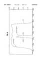
- FIG. 1is a schematic cross-sectional view, in elevation and partially broken away, of a gas bubble detector of this invention
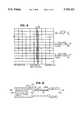
- FIG. 2is a plan view of a fitted mask, taken along 2--2 of FIG. 1,
- FIG. 3is a graph showing the response of an IR Bandpass filter between 3500 and 4000 cm -1 ,
- FIG. 4is a graph comparing water and air output versus lamp voltage
- FIG. 5is a graph comparing air/water ratio output signal versus lamp voltage at various duty cycles
- FIG. 6is a graph comparing water and air output signal versus modulation frequency at a duty cycle of 0.20
- FIG.7is a graph comparing lamp power versus lamp voltage for various duty cycles
- FIG. 8is a graph comparing an interference filter and a Pb-Se blocker superimposed
- FIG. 9shows a graph with channel 1, "x” demodulated signal; channel 2, "y” demodulated signal; and a construction
- ⁇ x 2 y 2 ,
- FIG. 10is an enlarged view of the tube and venturi of FIG. 1 showing gas bubbles of varying sizes in the liquid flow
- FIG. 11is a schematic of a demodulator and preprocessor circuit to produce the output
- ⁇ x 2 y 2 ,
- FIG. 12is a profile of the output signals of small and large gas bubbles as shown at the two outputs in
- FIG. 13is a timing diagram of the circuit of FIG. 11,
- FIG. 14shows the output of a small bubble and the output signals processed by the circuit of FIG. 11,
- FIG. 15shows the output of a large bubble and the output signals processed by the circuit of FIG. 11,
- FIG. 16is schematic diagram of a post processor circuit to process the output signal of the circuit of FIG. 11 and,
- FIG. 17is a schematic diagram of an analog circuit for vector magnitude computation.
- optical wavelengthsare small compared to the dimensions of the minimum bubble size to be detected.
- FIGS. 1 and 2show the construction of the gas bubble detector 10 of this invention.
- the gas bubble detector 10comprises a housing 12 forming an enclosure in which an incandescent lamp 14 is used as a modulated IR source.
- the lamp 14is connected to a source intensity modulator 16.
- a suitable reflector 18, preferably parabolic,focuses the output of the lamp 14 through a bandpass filter 20 supported on a glass plate 24.
- the bandpass filter 20comprises two plates, a lowpass filter 20a and a highpass filter 20b, whose response are shown superimposed to form a bandpass filter as shown in FIG. 3.
- the glass plate 24has an opening 26 through which the focused IR energy passes to illuminate a venturi 30 formed in part of a glass tube 32.
- the illuminated venturi 30is also referred to as the sample area.
- the glass tube 32 and venturi 30have a fitted opaque mask 34, as shown in FIG. 2, to block stray light within the housing 12.
- the glass plate 24 and mask 34are affixed within the housing 12 by any suitable means, such as by slots 36 and 40.
- the glass tube 32is held and sealed with respect to the housing 12 by a pair of compression fittings 42 which are conventional and commercially available.
- the material of the glass tube 32is a special glass formulated to have a low attenuation of IR energy which is readily available from commercial sources.
- the illumination of the venturi 30 by the focused IRis to detect bubbles in the fluid flowing through the venturi 30 represented by arrows 44.
- the change in IR energy when a bubble is present in the fluidis detected by an Pb--Se IR detector 46 and associated electronics 50, both of which are also commercially available as a unit.
- FIG. 3is an infrared spectrogram of the bandpass filter comprising a short wave plate 20a and a long wave plate 20b showing that the filter will pass only energy which lies within the absorption band of water 3500-4000 cm -1 , maximizing the ratio of the signal through air in the sample tube to the signal through the fluid to thus give a better signal-to-noise ratio.
- non-dispersive IR analyzersdue to AC coupling of the signal from the detector to the preamplifier, the IR energy must be intensity modulated when passing through the sample, and then the resulting AC signal must be demodulated to recover a steady-state representation of the absorptivity of the sample.
- Conventional non-dispersive IR analyzerscommonly use a motor-driven chopper to intensity modulate the light from the infrared source.
- a miniature incandescent lamp filamentis utilized, which may be electrically intensity modulated at a rapid rate due to its low thermal mass.
- Optimum frequency and duty cyclewere chosen experimentally to obtain the maximum ratio of output signal with air versus with water present inside the sample tube. The optimum frequencies is a function of the bandpass filter, the glass tube and other factors.
- sample Tube With Venturi ModificationThe original sample tube was 1 mm I.D. and 3 mm O.D., and minimum detectable bubble size was approximately the same as the I.D. of the tube (1 mm, or 0.039").
- the venturi 30was formed in the glass tube 32 as shown in FIG. 2 to provide a venturi I.D. of about 0.015".
- the minimum detectable bubble sizedecreased to approximately 0.004".
- the increased sensitivitywas due to (1) the smaller I.D. giving a larger ratio of light transmitted through bubbles smaller than 0.015" dia.
- FIG. 4is a plot of air and water signal amplitudes vs lamp voltage at a duty cycle of 0.20
- FIG. 5is a plot of air/water output ratio output signal vs lamp voltage at various duty cycles
- FIG. 6is a plot of water and air output signals vs frequency at a duty cycle of 0.20.
- the operating frequencywas chosen to be 3 kHz since that was the highest frequency at which signal-to-noise ratio was still acceptable.
- FIG. 5shows that the air-water ratio output signal peaks at a lamp voltage of 3.6 volts (still higher at 3.0 volts, point B, but FIG. 4 shows higher signal-to-noise ratio at 3.6 volts, point C); therefore, the operating point chosen was at a lamp voltage of 3.6 volts and duty cycle of 0.20.
- FIG. 7is a plot of lamp power vs lamp voltage for various duty cycles.
- FIG. 8is an interference filter with a Pb--Se blocker 56 superimposed to make the IR detector 46/50 non responsive to any other energy than that allowed through the filter.
- FIG. 7shows that at a duty cycle of 0.20 and lamp voltage of 3.6 volts, the lamp power is about 65 milliwatts, point D, which causes the lamp to glow a dull red color, indicating that the filament is not operating at a high enough temperature to cause reliability problems.
- FIGS. 4 and 5were taken with an IR interference filter installed which had the characteristics shown in FIG. 8, and before the sample tube 32 was modified with the venturi 30 in the sample area.
- the data shown in FIG. 6were taken with an IR bandpass filter 20 installed which had the characteristics shown in FIG. 3, after the venturi 30 was added.
- the bandpass filter bandwidthwas four times wider than the interference filter, resulting a signal amplitude increase of about 4:1.
- the improved air/water ratios shown in FIG. 6are primarily due to the wider bandpass filter. Adding the venturi 30 enabled detection of the smaller bubble sizes.
- the commonly accepted method of demodulation of the detected IR energyis to detect amplitude changes due to the increased transmission when air is present in the sample tube 32. This method is satisfactory when the bubble of air is present inside the sample tube 32 for several cycles of the modulating frequency.
- the bubblemay exist in the sample tube 32 for one cycle or less of the modulating frequency.
- the fluid velocityis ##EQU3## If the fluid flows at a rate of 30 ml/min and the sample tube I.D. is 0.015" the fluid velocity is, from eq. 3 ##EQU4## Assume a 0.015" dia. bubble passes through the sample tube without volume expansion due to reduced pressure in the venturi 30. The time for the bubble to pass through the sample area is ##EQU5##
- the modulation frequencyis 3 kHz
- the periodis 1/(3 kHz), or 333 microseconds.
- the portion of a cycle occupied by a 0.015" dia bubble moving through the sensor at 429 cm/secis then 89/333, or 26% of one cycle.
- Amplitude detection of the change in output produced from this amount of modulationwould be difficult to detect by simple amplitude detection.
- a bubble diameter of the minimum size specified (0.004")would occupy only about 6% of one cycle of modulation, and would be even more difficult to detect (volume expansion of the bubble due to decreased pressure in the venturi 30 may increase the time that the air is present in the sample area).
- the x (Ch1) and y (Ch2) components of the vectorwhich results from the IR energy transmission being enhanced by the momentary presence of air in the sample area, can be elicited or demodulated.
- the time-varying absolute magnitude of the x and y componentsis then calculated.
- the vector magnitudewas calculated graphically, but analog circuitry hereinafter discussed make this calculation continuously.
- the calculationconsists of (1) Synchronous demodulation of the detector output using the 3 kHz modulation frequency as one reference and a 90-degree phase-shifted 3 kHz modulation frequency as a second reference, which produces x and y components (this is equivalent to processing by the lock-in-amplifier), (2) Restoring the baseline to zero (equivalent to removing the carrier term), and (3) Computing the absolute magnitude vector continuously at every point along the x and y waveforms using an analog vector resolution circuit.
- steady-state increase in signalis determined by sensing a change in signal amplitude which exists for time period longer than a few modulation cycles, using an amplitude modulation detector and a comparator.
- FIG. 10is an enlargement of the sample tube and shows the venturi 30 and the flow of fluid 44 with two different sizes of small bubbles 44a and 44b and a large bubble 44c.
- waveform 60arepresents the area of the smallest bubble 40a
- waveform 60brepresents the area of the larger small bubble 40b.
- the area of the pulse waveformrepresents the area of a detected bubble, and an area-to-volume calculation may be performed based upon calibration of the system with bubbles of known volume.
- the two different sizes of small bubbles and the detection of the large bubble over time ⁇ tis shown in FIG. 12.
- the output fxis connected to a switch 70.
- a second divide-by-2 counter 72is connected at node 1 to provide frequency fy and which is connected to another switch 74.
- FIG. 13shows the timing diagram in which the original oscillator frequency is divided to form frequencies fx and fy.
- Another branch of the circuit of FIG. 11comprises the IR source 14 as detected by the IR detector and electronics 46/50 (FIG. 1) which in turn is connected to a bandpass filter 76.
- the IR source intensityis modulated by the IR source modulator 16.
- the output of the bandpass filter 76is coupled at node 2 to circuitry to detect small bubbles and is coupled at node 4 to circuitry to detect large bubbles.
- the output of the bandpass filter 76is coupled to the switches 70 and 74 through a pair of operational amplifiers 80 and 82 which function as buffers.
- the output of switch 70is connected to lowpass filter 84, to a buffer amplifier 86 and then to a highpass filter 90.
- the output of filter 90is designated as e 1 .
- the output of switch 74is connected to a second lowpass filter 92, to a second buffer amplifier 94 and then to a second highpass filter 96.
- the output of filter 96is designated as e 2 .
- the highpass filters 90 and 96remove the DC level which results from demodulation of the unmodulated carrier, thus "restoring" the baseline, or zero reference, of the demodulated signal which resulted from a bubble interrupting the optical path.
- the output e 1is multiplied at multiplier 100 to provide x 2 and the output e 2 is multiplied at multiplier 102 to provide y 2 .
- the output of these two multipliersare connected at node 3 between a voltage divider network 104 and through an inverter 106 to provide an output x 2 +y 2 .
- This outputis connected to a divider 110 to provide the square root of x 2 +y 2 which is the output e o , waveform 60.
- the circuitry for squaring the x and y components, adding the x 2 and y 2 components and taking the square root of the sum of x 2 and y 2is shown in FIG. 17 and is a commercially available analog multiplier chip connected as a square root circuit.
- the output of the bandpass filter 76is connected at node 4 to an amplitude modulation detector 112 whose output is connected to one input of a comparator 114.
- the other input to the comparatoris connected to a reference voltage V 1 .
- the output of the comparator 114is connected to a processor 116, which is also connected to the post processor circuitry of FIG. 16 to be described.
- FIGS. 12, 14 and 15there is shown the output of the bandpass filter 76 as processed by the remainder of the circuit of FIG. 11.
- FIG. 14 and particularly FIG. 14ashows the output of the bandpass filter 76, with a small bubble being detected in the venturi 30 changes in the amplitude of the modulation frequency which are processed by the circuit of FIG. 11 to form the x and y signals as they would appear at the output of the highpass filters 83 and 84, e 1 and e 2 , respectively.
- These signalsare processed to form the output signal e o ,FIG. 14c.
- the processing of these signalscorrespond to the signals of FIG. 9.
- Channel 1corresponds to x of FIG. 11
- channel 2corresponds to y of FIG. 11
- zcorresponds to the output e o of FIG. 11.
- FIG. 15shows the modulation frequency at the output of the bandpass filter 76 where a large bubble is being detected in the venturi 30.
- This large bubblecauses a large decrease in the amplitude of the modulation frequency extending over several cycles as in FIG. 15a which is detected by the amplitude modulation detector 112 and compared in the comparator 114 with the threshold voltage reference V 1 which produces an output signal ⁇ t corresponding to the length of time the amplitude of the envelope is below the threshold voltage.
- the detection of this large bubbleis sent to the processor 116.
- the time width ⁇ tis measured by the processor 116 and converted into gas volume, knowing the flow velocity and the ratio of the diameter of the flow tube 32 to the diameter of the venturi 30. If the time ⁇ t is exceedingly long, the processor may provide an alarm indicating no fluid in the system.
- FIG. 16illustrates the post processor circuit for processing the output from the circuit of FIG. 11.
- the output of the circuit of FIG. 11is connected at node 5 to the input of an integrator 120 through a resistor 122.
- the integrator 120includes an operational amplifier 124, an integrator capacitor 126 connected across the operational amplifier and an integrator reset switch 128 connected across the capacitor 126.
- the output of the integrator 120is also connected, 1), to an analog-to-digital converter 130 and to processor 116 (see also FIG. 11) and, 2), at node 7 to one input of a comparator 132 whose other input is connected to a reference voltage V 2 .
- the output of the comparator 132is connected to a one-shot multivibrator 134 the output of which, in turn, is connected at node 8 to a counter 136.
- the output of the counter 136is in parallel as at 138 and connected to a data bus (not shown) of processor 116.
- the counter 136has another output connected to an overflow signal line 140 which, in turn, is connected to the data bus of processor 116.
- This latter overflow signal line 140is activated when the counter reaches maximum possible count (ie, 2 16 for a 16 bit counter) for a small bubble and signals the presence of a large bubble and/or no fluid in the sample area.
- the overflow signal line 140may be connected to activate an alarm.
- the counter 136is connected at node 9 to a reset input 142. Reset input 142 is also connected to an AND gate 144 at node 9. The other input to the AND gate 144 is connected at node 8 to the output of the multivibrator 134.
- the output of the comparator 132resets the output of the integrator 120 to zero when the integrator output increases above a maximum voltage, which is determined by the reference voltage V 2 .
- the integrator output voltageis limited to a maximum value determined by the integrator power supply (not shown). If the output of the integrator 120 were allowed to exceed this voltage, the output would become saturated and would no longer be useful for indicating the volume of the gas bubbles.
- the one-shot multivibrator 134develops a pulse of sufficient time to allow the reset switch 128 to fully discharge the capacitor 126 of the integrator 120. Whenever a small bubble is detected, the output voltage of the integrator 120 will increment a small amount, proportional to the area of the bubble.
- the integrator output voltageis connected to the A/D converter 130 to enable the integrator output to be sampled periodically by the processor 116 where the information is converted into a history of the size of each bubble which was detected and when it was detected.
- the output of counter 136represents the total number of times the integrator 120 was reset, which corresponds to the total area of bubbles measured, starting at the time the counter 136 was reset to zero.
- processor 116Normally the processor 116 would read the output of the counter 136 periodically, and then resets it by a pulse on line 142. If an overflow signal on line 140 is presented to the processor 116, this signal is read by the processor 116 on a priority interrupt and then the processor 116 will reset the counter 136 as before.
Landscapes
- Physics & Mathematics (AREA)
- Health & Medical Sciences (AREA)
- Life Sciences & Earth Sciences (AREA)
- Chemical & Material Sciences (AREA)
- Analytical Chemistry (AREA)
- Biochemistry (AREA)
- General Health & Medical Sciences (AREA)
- General Physics & Mathematics (AREA)
- Immunology (AREA)
- Pathology (AREA)
- Investigating Or Analysing Materials By Optical Means (AREA)
Abstract
Description
Claims (26)
Priority Applications (1)
| Application Number | Priority Date | Filing Date | Title |
|---|---|---|---|
| US08/112,008US5455423A (en) | 1993-08-25 | 1993-08-25 | Gas bubble detector |
Applications Claiming Priority (1)
| Application Number | Priority Date | Filing Date | Title |
|---|---|---|---|
| US08/112,008US5455423A (en) | 1993-08-25 | 1993-08-25 | Gas bubble detector |
Publications (1)
| Publication Number | Publication Date |
|---|---|
| US5455423Atrue US5455423A (en) | 1995-10-03 |
Family
ID=22341644
Family Applications (1)
| Application Number | Title | Priority Date | Filing Date |
|---|---|---|---|
| US08/112,008Expired - Fee RelatedUS5455423A (en) | 1993-08-25 | 1993-08-25 | Gas bubble detector |
Country Status (1)
| Country | Link |
|---|---|
| US (1) | US5455423A (en) |
Cited By (38)
| Publication number | Priority date | Publication date | Assignee | Title |
|---|---|---|---|---|
| US5960129A (en)* | 1997-12-22 | 1999-09-28 | Bayer Corporation | Method and apparatus for detecting liquid and gas segment flow through a tube |
| GB2336905A (en)* | 1998-04-29 | 1999-11-03 | Wrc Plc | Method and apparatus for monitoring bubbles in a liquid |
| US6037592A (en)* | 1997-02-14 | 2000-03-14 | Underground Systems, Inc. | System for measuring gases dissolved in a liquid |
| US20020145122A1 (en)* | 2001-02-15 | 2002-10-10 | Systems And Methods For Detection And | Systems and methods for detection and measurement of elements in a medium |
| US6538739B1 (en) | 1997-09-30 | 2003-03-25 | The Regents Of The University Of California | Bubble diagnostics |
| US6616633B1 (en)* | 1997-09-19 | 2003-09-09 | Alaris Medical Systems, Inc. | Apparatus and method for air-in-line detection |
| EP1617202A1 (en)* | 2004-07-13 | 2006-01-18 | Services Petroliers Schlumberger | Detector for distinguishing phases in a multiphase fluid mixture |
| US20060021419A1 (en)* | 2004-05-28 | 2006-02-02 | Cassidy David E | Gas detection in an intravenous fluid delivery system |
| US20070165231A1 (en)* | 2006-01-19 | 2007-07-19 | Robert Frodl | Gas Sensor And Method For The Production Thereof |
| US20080277586A1 (en)* | 2007-05-07 | 2008-11-13 | Dennis Cardinale | Low-Power Fast Infrared Gas Sensor, Hand Held Gas Leak Detector, and Gas Monitor Utilizing Absorptive-Photo-Acoustic Detection |
| US20090050809A1 (en)* | 2004-03-12 | 2009-02-26 | Henry Victor Holec | Fluid Flow Monitoring Device |
| US20090088687A1 (en)* | 2007-10-01 | 2009-04-02 | Baxter International Inc. | Medical fluid air bubble detection apparatus and method |
| US20090097029A1 (en)* | 2007-10-11 | 2009-04-16 | Ecolab Inc. | Optical product detection sensor |
| US20090262351A1 (en)* | 2007-10-11 | 2009-10-22 | Ecolab Inc. | Optical product detection sensor |
| DE10021944B4 (en)* | 1999-05-07 | 2011-03-10 | Leco Corp., St. Joseph | Switched non-dispersive IR detection system |
| WO2014194065A1 (en)* | 2013-05-29 | 2014-12-04 | Hospira, Inc. | Infusion system and method of use which prevents over-saturation of an analog-to-digital converter |
| US9995611B2 (en) | 2012-03-30 | 2018-06-12 | Icu Medical, Inc. | Air detection system and method for detecting air in a pump of an infusion system |
| US10022498B2 (en) | 2011-12-16 | 2018-07-17 | Icu Medical, Inc. | System for monitoring and delivering medication to a patient and method of using the same to minimize the risks associated with automated therapy |
| US10046112B2 (en) | 2013-05-24 | 2018-08-14 | Icu Medical, Inc. | Multi-sensor infusion system for detecting air or an occlusion in the infusion system |
| US10166328B2 (en) | 2013-05-29 | 2019-01-01 | Icu Medical, Inc. | Infusion system which utilizes one or more sensors and additional information to make an air determination regarding the infusion system |
| US10342917B2 (en) | 2014-02-28 | 2019-07-09 | Icu Medical, Inc. | Infusion system and method which utilizes dual wavelength optical air-in-line detection |
| US10352866B1 (en) | 2018-04-09 | 2019-07-16 | Mehmet Arbatli | System and method of detecting within a liquid flow of a pipe |
| US10430761B2 (en) | 2011-08-19 | 2019-10-01 | Icu Medical, Inc. | Systems and methods for a graphical interface including a graphical representation of medical data |
| US10463788B2 (en) | 2012-07-31 | 2019-11-05 | Icu Medical, Inc. | Patient care system for critical medications |
| US10635784B2 (en) | 2007-12-18 | 2020-04-28 | Icu Medical, Inc. | User interface improvements for medical devices |
| US10656894B2 (en) | 2017-12-27 | 2020-05-19 | Icu Medical, Inc. | Synchronized display of screen content on networked devices |
| US10850024B2 (en) | 2015-03-02 | 2020-12-01 | Icu Medical, Inc. | Infusion system, device, and method having advanced infusion features |
| US11135360B1 (en) | 2020-12-07 | 2021-10-05 | Icu Medical, Inc. | Concurrent infusion with common line auto flush |
| US11246985B2 (en) | 2016-05-13 | 2022-02-15 | Icu Medical, Inc. | Infusion pump system and method with common line auto flush |
| US11278671B2 (en) | 2019-12-04 | 2022-03-22 | Icu Medical, Inc. | Infusion pump with safety sequence keypad |
| US11324888B2 (en) | 2016-06-10 | 2022-05-10 | Icu Medical, Inc. | Acoustic flow sensor for continuous medication flow measurements and feedback control of infusion |
| US11344673B2 (en) | 2014-05-29 | 2022-05-31 | Icu Medical, Inc. | Infusion system and pump with configurable closed loop delivery rate catch-up |
| US11344668B2 (en) | 2014-12-19 | 2022-05-31 | Icu Medical, Inc. | Infusion system with concurrent TPN/insulin infusion |
| US11768142B1 (en) | 2021-04-12 | 2023-09-26 | Mehmet Arbatli | Bubble detection system and method within a liquid flow of a pipe by sensing changes in local liquid pressure |
| US11883361B2 (en) | 2020-07-21 | 2024-01-30 | Icu Medical, Inc. | Fluid transfer devices and methods of use |
| US11982683B1 (en) | 2021-04-12 | 2024-05-14 | Mehmet Arbatli | System and method of detecting skimmer and pump basket clogging by sensing changes in local liquid pressure |
| US12350233B2 (en) | 2021-12-10 | 2025-07-08 | Icu Medical, Inc. | Medical fluid compounding systems with coordinated flow control |
| USD1091564S1 (en) | 2021-10-13 | 2025-09-02 | Icu Medical, Inc. | Display screen or portion thereof with graphical user interface for a medical device |
Citations (5)
| Publication number | Priority date | Publication date | Assignee | Title |
|---|---|---|---|---|
| US3705771A (en)* | 1970-01-14 | 1972-12-12 | Bio Physics Systems Inc | Photoanalysis apparatus |
| US3898637A (en)* | 1973-07-27 | 1975-08-05 | Eugene B Wolstenholme | Detection means for gas entering human blood system from extra-corporeal tubing |
| US4344429A (en)* | 1979-12-13 | 1982-08-17 | Baxter Travenol Laboratories, Inc. | Bubble detector with feedback circuit for improved sensitivity |
| US4371786A (en)* | 1980-10-29 | 1983-02-01 | Miles Laboratories, Inc. | Method and apparatus for detecting bubbles in a liquid |
| US5078683A (en)* | 1990-05-04 | 1992-01-07 | Block Medical, Inc. | Programmable infusion system |
- 1993
- 1993-08-25USUS08/112,008patent/US5455423A/ennot_activeExpired - Fee Related
Patent Citations (5)
| Publication number | Priority date | Publication date | Assignee | Title |
|---|---|---|---|---|
| US3705771A (en)* | 1970-01-14 | 1972-12-12 | Bio Physics Systems Inc | Photoanalysis apparatus |
| US3898637A (en)* | 1973-07-27 | 1975-08-05 | Eugene B Wolstenholme | Detection means for gas entering human blood system from extra-corporeal tubing |
| US4344429A (en)* | 1979-12-13 | 1982-08-17 | Baxter Travenol Laboratories, Inc. | Bubble detector with feedback circuit for improved sensitivity |
| US4371786A (en)* | 1980-10-29 | 1983-02-01 | Miles Laboratories, Inc. | Method and apparatus for detecting bubbles in a liquid |
| US5078683A (en)* | 1990-05-04 | 1992-01-07 | Block Medical, Inc. | Programmable infusion system |
Cited By (70)
| Publication number | Priority date | Publication date | Assignee | Title |
|---|---|---|---|---|
| US6037592A (en)* | 1997-02-14 | 2000-03-14 | Underground Systems, Inc. | System for measuring gases dissolved in a liquid |
| US6616633B1 (en)* | 1997-09-19 | 2003-09-09 | Alaris Medical Systems, Inc. | Apparatus and method for air-in-line detection |
| US6538739B1 (en) | 1997-09-30 | 2003-03-25 | The Regents Of The University Of California | Bubble diagnostics |
| US5960129A (en)* | 1997-12-22 | 1999-09-28 | Bayer Corporation | Method and apparatus for detecting liquid and gas segment flow through a tube |
| GB2336905A (en)* | 1998-04-29 | 1999-11-03 | Wrc Plc | Method and apparatus for monitoring bubbles in a liquid |
| GB2336905B (en)* | 1998-04-29 | 2003-07-02 | Wrc Plc | Apparatus for monitoring bubbles in a liquid |
| DE10021944B4 (en)* | 1999-05-07 | 2011-03-10 | Leco Corp., St. Joseph | Switched non-dispersive IR detection system |
| US20020145122A1 (en)* | 2001-02-15 | 2002-10-10 | Systems And Methods For Detection And | Systems and methods for detection and measurement of elements in a medium |
| US6969865B2 (en)* | 2001-02-15 | 2005-11-29 | Acist Medical Systems, Inc. | Systems and methods for detection and measurement of elements in a medium |
| US20090050809A1 (en)* | 2004-03-12 | 2009-02-26 | Henry Victor Holec | Fluid Flow Monitoring Device |
| US20060021419A1 (en)* | 2004-05-28 | 2006-02-02 | Cassidy David E | Gas detection in an intravenous fluid delivery system |
| US7377148B2 (en)* | 2004-05-28 | 2008-05-27 | Enginivity, Llc | Capacitor-based gas detection in an intravenous fluid delivery system |
| EP1617202A1 (en)* | 2004-07-13 | 2006-01-18 | Services Petroliers Schlumberger | Detector for distinguishing phases in a multiphase fluid mixture |
| US20070165231A1 (en)* | 2006-01-19 | 2007-07-19 | Robert Frodl | Gas Sensor And Method For The Production Thereof |
| US20080277586A1 (en)* | 2007-05-07 | 2008-11-13 | Dennis Cardinale | Low-Power Fast Infrared Gas Sensor, Hand Held Gas Leak Detector, and Gas Monitor Utilizing Absorptive-Photo-Acoustic Detection |
| US20090088687A1 (en)* | 2007-10-01 | 2009-04-02 | Baxter International Inc. | Medical fluid air bubble detection apparatus and method |
| US8033157B2 (en)* | 2007-10-01 | 2011-10-11 | Baxter International Inc. | Medical fluid air bubble detection apparatus and method |
| US20090097029A1 (en)* | 2007-10-11 | 2009-04-16 | Ecolab Inc. | Optical product detection sensor |
| US20090262351A1 (en)* | 2007-10-11 | 2009-10-22 | Ecolab Inc. | Optical product detection sensor |
| US7924424B2 (en) | 2007-10-11 | 2011-04-12 | Ecolab Usa Inc. | Optical product detection sensor |
| US8004683B2 (en) | 2007-10-11 | 2011-08-23 | Ecolab Usa Inc. | Optical product detection sensor |
| US10635784B2 (en) | 2007-12-18 | 2020-04-28 | Icu Medical, Inc. | User interface improvements for medical devices |
| US11599854B2 (en) | 2011-08-19 | 2023-03-07 | Icu Medical, Inc. | Systems and methods for a graphical interface including a graphical representation of medical data |
| US11972395B2 (en) | 2011-08-19 | 2024-04-30 | Icu Medical, Inc. | Systems and methods for a graphical interface including a graphical representation of medical data |
| US11004035B2 (en) | 2011-08-19 | 2021-05-11 | Icu Medical, Inc. | Systems and methods for a graphical interface including a graphical representation of medical data |
| US12346879B2 (en) | 2011-08-19 | 2025-07-01 | Icu Medical, Inc. | Systems and methods for a graphical interface including a graphical representation of medical data |
| US10430761B2 (en) | 2011-08-19 | 2019-10-01 | Icu Medical, Inc. | Systems and methods for a graphical interface including a graphical representation of medical data |
| US10022498B2 (en) | 2011-12-16 | 2018-07-17 | Icu Medical, Inc. | System for monitoring and delivering medication to a patient and method of using the same to minimize the risks associated with automated therapy |
| US11376361B2 (en) | 2011-12-16 | 2022-07-05 | Icu Medical, Inc. | System for monitoring and delivering medication to a patient and method of using the same to minimize the risks associated with automated therapy |
| US11933650B2 (en) | 2012-03-30 | 2024-03-19 | Icu Medical, Inc. | Air detection system and method for detecting air in a pump of an infusion system |
| US10578474B2 (en) | 2012-03-30 | 2020-03-03 | Icu Medical, Inc. | Air detection system and method for detecting air in a pump of an infusion system |
| US9995611B2 (en) | 2012-03-30 | 2018-06-12 | Icu Medical, Inc. | Air detection system and method for detecting air in a pump of an infusion system |
| US11623042B2 (en) | 2012-07-31 | 2023-04-11 | Icu Medical, Inc. | Patient care system for critical medications |
| US10463788B2 (en) | 2012-07-31 | 2019-11-05 | Icu Medical, Inc. | Patient care system for critical medications |
| US12280239B2 (en) | 2012-07-31 | 2025-04-22 | Icu Medical, Inc. | Patient care system for critical medications |
| US12048831B2 (en) | 2013-05-24 | 2024-07-30 | Icu Medical, Inc. | Multi-sensor infusion system for detecting air or an occlusion in the infusion system |
| US10874793B2 (en) | 2013-05-24 | 2020-12-29 | Icu Medical, Inc. | Multi-sensor infusion system for detecting air or an occlusion in the infusion system |
| US10046112B2 (en) | 2013-05-24 | 2018-08-14 | Icu Medical, Inc. | Multi-sensor infusion system for detecting air or an occlusion in the infusion system |
| US11596737B2 (en) | 2013-05-29 | 2023-03-07 | Icu Medical, Inc. | Infusion system and method of use which prevents over-saturation of an analog-to-digital converter |
| US12059551B2 (en) | 2013-05-29 | 2024-08-13 | Icu Medical, Inc. | Infusion system and method of use which prevents over-saturation of an analog-to-digital converter |
| US10596316B2 (en) | 2013-05-29 | 2020-03-24 | Icu Medical, Inc. | Infusion system and method of use which prevents over-saturation of an analog-to-digital converter |
| US9707341B2 (en) | 2013-05-29 | 2017-07-18 | Icu Medical, Inc. | Infusion system and method of use which prevents over-saturation of an analog-to-digital converter |
| US10166328B2 (en) | 2013-05-29 | 2019-01-01 | Icu Medical, Inc. | Infusion system which utilizes one or more sensors and additional information to make an air determination regarding the infusion system |
| WO2014194065A1 (en)* | 2013-05-29 | 2014-12-04 | Hospira, Inc. | Infusion system and method of use which prevents over-saturation of an analog-to-digital converter |
| US11433177B2 (en) | 2013-05-29 | 2022-09-06 | Icu Medical, Inc. | Infusion system which utilizes one or more sensors and additional information to make an air determination regarding the infusion system |
| US12083310B2 (en) | 2014-02-28 | 2024-09-10 | Icu Medical, Inc. | Infusion system and method which utilizes dual wavelength optical air-in-line detection |
| US10342917B2 (en) | 2014-02-28 | 2019-07-09 | Icu Medical, Inc. | Infusion system and method which utilizes dual wavelength optical air-in-line detection |
| US11344673B2 (en) | 2014-05-29 | 2022-05-31 | Icu Medical, Inc. | Infusion system and pump with configurable closed loop delivery rate catch-up |
| US11344668B2 (en) | 2014-12-19 | 2022-05-31 | Icu Medical, Inc. | Infusion system with concurrent TPN/insulin infusion |
| US10850024B2 (en) | 2015-03-02 | 2020-12-01 | Icu Medical, Inc. | Infusion system, device, and method having advanced infusion features |
| US12115337B2 (en) | 2015-03-02 | 2024-10-15 | Icu Medical, Inc. | Infusion system, device, and method having advanced infusion features |
| US11246985B2 (en) | 2016-05-13 | 2022-02-15 | Icu Medical, Inc. | Infusion pump system and method with common line auto flush |
| US12201811B2 (en) | 2016-05-13 | 2025-01-21 | Icu Medical, Inc. | Infusion pump system and method with common line auto flush |
| US11324888B2 (en) | 2016-06-10 | 2022-05-10 | Icu Medical, Inc. | Acoustic flow sensor for continuous medication flow measurements and feedback control of infusion |
| US12076531B2 (en) | 2016-06-10 | 2024-09-03 | Icu Medical, Inc. | Acoustic flow sensor for continuous medication flow measurements and feedback control of infusion |
| US12333201B2 (en) | 2017-12-27 | 2025-06-17 | Icu Medical, Inc. | Synchronized display of screen content on networked devices |
| US11868161B2 (en) | 2017-12-27 | 2024-01-09 | Icu Medical, Inc. | Synchronized display of screen content on networked devices |
| US10656894B2 (en) | 2017-12-27 | 2020-05-19 | Icu Medical, Inc. | Synchronized display of screen content on networked devices |
| US11029911B2 (en) | 2017-12-27 | 2021-06-08 | Icu Medical, Inc. | Synchronized display of screen content on networked devices |
| US10352866B1 (en) | 2018-04-09 | 2019-07-16 | Mehmet Arbatli | System and method of detecting within a liquid flow of a pipe |
| US12268843B2 (en) | 2019-12-04 | 2025-04-08 | Icu Medical, Inc. | Infusion pump with safety sequence keypad |
| US11278671B2 (en) | 2019-12-04 | 2022-03-22 | Icu Medical, Inc. | Infusion pump with safety sequence keypad |
| US11883361B2 (en) | 2020-07-21 | 2024-01-30 | Icu Medical, Inc. | Fluid transfer devices and methods of use |
| US12310921B2 (en) | 2020-07-21 | 2025-05-27 | Icu Medical, Inc. | Fluid transfer devices and methods of use |
| US11135360B1 (en) | 2020-12-07 | 2021-10-05 | Icu Medical, Inc. | Concurrent infusion with common line auto flush |
| US12390586B2 (en) | 2020-12-07 | 2025-08-19 | Icu Medical, Inc. | Concurrent infusion with common line auto flush |
| US11982683B1 (en) | 2021-04-12 | 2024-05-14 | Mehmet Arbatli | System and method of detecting skimmer and pump basket clogging by sensing changes in local liquid pressure |
| US11768142B1 (en) | 2021-04-12 | 2023-09-26 | Mehmet Arbatli | Bubble detection system and method within a liquid flow of a pipe by sensing changes in local liquid pressure |
| USD1091564S1 (en) | 2021-10-13 | 2025-09-02 | Icu Medical, Inc. | Display screen or portion thereof with graphical user interface for a medical device |
| US12350233B2 (en) | 2021-12-10 | 2025-07-08 | Icu Medical, Inc. | Medical fluid compounding systems with coordinated flow control |
Similar Documents
| Publication | Publication Date | Title |
|---|---|---|
| US5455423A (en) | Gas bubble detector | |
| US3864044A (en) | Method and apparatus for the analysis of a dispersed phase capable of transmitting and focusing light | |
| US3824391A (en) | Methods of and apparatus for flame monitoring | |
| ATE45812T1 (en) | INFRARED ABSORPTION GAS DETECTION DEVICE. | |
| AU4737485A (en) | Fluctuation analysis for enhanced particle detection | |
| US4281248A (en) | Nondispersive infrared gas analyzer | |
| EP0008874B1 (en) | Method and apparatus for discriminating red blood cells from platelets | |
| US5594421A (en) | Method and detector for detecting a flame | |
| SE8800686L (en) | PROCEDURE AND DEVICE FOR DETERMINING THE CONCENTRATION OF A SUBSTANCE CONNECTED TO PARTICLES IN A FLOWING MEDIUM | |
| US5453620A (en) | Nondispersive infrared gas analyzer and gas sample chamber used therein | |
| JP2001004444A (en) | Switching type ndir system | |
| US4891518A (en) | Apparatus for detecting a plurality of gases | |
| SE7908324L (en) | PROCEDURE AND DEVICE FOR OPTICAL SEPARATION OF PROVOBS | |
| GB2338299A (en) | Improved Rayleigh backscatter control apparatus and method | |
| US4605313A (en) | Infrared detector for NDIR gas analysis | |
| JPS61194332A (en) | Method and device for measuring gas concentration | |
| Mount et al. | Gas bubble detector | |
| JPS6474696A (en) | Method and device for fire alarm | |
| US5796481A (en) | Suspended particle concentration monitor | |
| DK1055113T3 (en) | Method for detecting the presence of water on a surface | |
| JP3333646B2 (en) | Infrared human body detector | |
| JPS60147607A (en) | Measuring method of particle size using laser Doppler velocimeter | |
| SU1589142A1 (en) | Device for determining size of particles | |
| JPH05240782A (en) | Oil concentration measuring device | |
| SU1267169A1 (en) | Optical absorption gas analyzer |
Legal Events
| Date | Code | Title | Description |
|---|---|---|---|
| AS | Assignment | Owner name:ORBITAL SCIENCES CORPORATION, VIRGINIA Free format text:ASSIGNMENT OF ASSIGNORS INTEREST;ASSIGNOR:PERKIN-ELMER CORPORATION;REEL/FRAME:006804/0063 Effective date:19930917 | |
| REMI | Maintenance fee reminder mailed | ||
| LAPS | Lapse for failure to pay maintenance fees | ||
| FP | Lapsed due to failure to pay maintenance fee | Effective date:19991003 | |
| AS | Assignment | Owner name:MORGAN GUARANTY TRUST COMPANY OF NEW YORK, AS COLL Free format text:SECURITY AGREEMENT;ASSIGNOR:ORBITAL SCIENCES CORPORATION;REEL/FRAME:010703/0401 Effective date:19991130 | |
| AS | Assignment | Owner name:JPMORGAN CHASE BANK, NEW YORK Free format text:MERGER AND CHANGE OF NAME;ASSIGNOR:MORGAN GURANTY TRUST COMPANY OF NEW YORK;REEL/FRAME:012735/0144 Effective date:20011110 | |
| AS | Assignment | Owner name:ORBITAL SCIENCES CORPORATION, VIRGINIA Free format text:RELEASE OF SECURITY AGREEMENT;ASSIGNOR:JPMORGAN CHASE BANK;REEL/FRAME:012495/0611 Effective date:20020123 | |
| AS | Assignment | Owner name:FOOTHILL CAPITAL CORPORATION, AS AGENT, GEORGIA Free format text:SECURITY AGREEMENT;ASSIGNOR:ORBITAL SCIENCES CORPORATION;REEL/FRAME:012729/0899 Effective date:20020301 | |
| STCH | Information on status: patent discontinuation | Free format text:PATENT EXPIRED DUE TO NONPAYMENT OF MAINTENANCE FEES UNDER 37 CFR 1.362 |