US5455387A - Semiconductor package with chip redistribution interposer - Google Patents
Semiconductor package with chip redistribution interposerDownload PDFInfo
- Publication number
- US5455387A US5455387AUS08/276,564US27656494AUS5455387AUS 5455387 AUS5455387 AUS 5455387AUS 27656494 AUS27656494 AUS 27656494AUS 5455387 AUS5455387 AUS 5455387A
- Authority
- US
- United States
- Prior art keywords
- interposer
- redistribution
- lead frame
- electronic package
- chip
- Prior art date
- Legal status (The legal status is an assumption and is not a legal conclusion. Google has not performed a legal analysis and makes no representation as to the accuracy of the status listed.)
- Expired - Fee Related
Links
- 239000004065semiconductorSubstances0.000titleclaimsabstractdescription9
- 239000002184metalSubstances0.000claimsabstractdescription5
- 239000004020conductorSubstances0.000claimsdescription27
- 229910010293ceramic materialInorganic materials0.000claimsdescription3
- 238000000034methodMethods0.000description3
- 230000017525heat dissipationEffects0.000description2
- 238000012986modificationMethods0.000description2
- 230000004048modificationEffects0.000description2
- 239000000919ceramicSubstances0.000description1
Images


Classifications
- H—ELECTRICITY
- H01—ELECTRIC ELEMENTS
- H01L—SEMICONDUCTOR DEVICES NOT COVERED BY CLASS H10
- H01L23/00—Details of semiconductor or other solid state devices
- H01L23/02—Containers; Seals
- H01L23/04—Containers; Seals characterised by the shape of the container or parts, e.g. caps, walls
- H—ELECTRICITY
- H01—ELECTRIC ELEMENTS
- H01L—SEMICONDUCTOR DEVICES NOT COVERED BY CLASS H10
- H01L23/00—Details of semiconductor or other solid state devices
- H01L23/48—Arrangements for conducting electric current to or from the solid state body in operation, e.g. leads, terminal arrangements ; Selection of materials therefor
- H01L23/488—Arrangements for conducting electric current to or from the solid state body in operation, e.g. leads, terminal arrangements ; Selection of materials therefor consisting of soldered or bonded constructions
- H01L23/495—Lead-frames or other flat leads
- H01L23/49517—Additional leads
- H01L23/4952—Additional leads the additional leads being a bump or a wire
- H—ELECTRICITY
- H01—ELECTRIC ELEMENTS
- H01L—SEMICONDUCTOR DEVICES NOT COVERED BY CLASS H10
- H01L23/00—Details of semiconductor or other solid state devices
- H01L23/48—Arrangements for conducting electric current to or from the solid state body in operation, e.g. leads, terminal arrangements ; Selection of materials therefor
- H01L23/488—Arrangements for conducting electric current to or from the solid state body in operation, e.g. leads, terminal arrangements ; Selection of materials therefor consisting of soldered or bonded constructions
- H01L23/495—Lead-frames or other flat leads
- H01L23/49517—Additional leads
- H01L23/49531—Additional leads the additional leads being a wiring board
- H—ELECTRICITY
- H01—ELECTRIC ELEMENTS
- H01L—SEMICONDUCTOR DEVICES NOT COVERED BY CLASS H10
- H01L23/00—Details of semiconductor or other solid state devices
- H01L23/48—Arrangements for conducting electric current to or from the solid state body in operation, e.g. leads, terminal arrangements ; Selection of materials therefor
- H01L23/488—Arrangements for conducting electric current to or from the solid state body in operation, e.g. leads, terminal arrangements ; Selection of materials therefor consisting of soldered or bonded constructions
- H01L23/495—Lead-frames or other flat leads
- H01L23/49534—Multi-layer
- H—ELECTRICITY
- H01—ELECTRIC ELEMENTS
- H01L—SEMICONDUCTOR DEVICES NOT COVERED BY CLASS H10
- H01L2224/00—Indexing scheme for arrangements for connecting or disconnecting semiconductor or solid-state bodies and methods related thereto as covered by H01L24/00
- H01L2224/01—Means for bonding being attached to, or being formed on, the surface to be connected, e.g. chip-to-package, die-attach, "first-level" interconnects; Manufacturing methods related thereto
- H01L2224/42—Wire connectors; Manufacturing methods related thereto
- H01L2224/47—Structure, shape, material or disposition of the wire connectors after the connecting process
- H01L2224/48—Structure, shape, material or disposition of the wire connectors after the connecting process of an individual wire connector
- H01L2224/4805—Shape
- H01L2224/4809—Loop shape
- H01L2224/48091—Arched
- H—ELECTRICITY
- H01—ELECTRIC ELEMENTS
- H01L—SEMICONDUCTOR DEVICES NOT COVERED BY CLASS H10
- H01L2224/00—Indexing scheme for arrangements for connecting or disconnecting semiconductor or solid-state bodies and methods related thereto as covered by H01L24/00
- H01L2224/01—Means for bonding being attached to, or being formed on, the surface to be connected, e.g. chip-to-package, die-attach, "first-level" interconnects; Manufacturing methods related thereto
- H01L2224/42—Wire connectors; Manufacturing methods related thereto
- H01L2224/47—Structure, shape, material or disposition of the wire connectors after the connecting process
- H01L2224/48—Structure, shape, material or disposition of the wire connectors after the connecting process of an individual wire connector
- H01L2224/481—Disposition
- H01L2224/48151—Connecting between a semiconductor or solid-state body and an item not being a semiconductor or solid-state body, e.g. chip-to-substrate, chip-to-passive
- H01L2224/48221—Connecting between a semiconductor or solid-state body and an item not being a semiconductor or solid-state body, e.g. chip-to-substrate, chip-to-passive the body and the item being stacked
- H01L2224/48245—Connecting between a semiconductor or solid-state body and an item not being a semiconductor or solid-state body, e.g. chip-to-substrate, chip-to-passive the body and the item being stacked the item being metallic
- H01L2224/48247—Connecting between a semiconductor or solid-state body and an item not being a semiconductor or solid-state body, e.g. chip-to-substrate, chip-to-passive the body and the item being stacked the item being metallic connecting the wire to a bond pad of the item
- H—ELECTRICITY
- H01—ELECTRIC ELEMENTS
- H01L—SEMICONDUCTOR DEVICES NOT COVERED BY CLASS H10
- H01L2224/00—Indexing scheme for arrangements for connecting or disconnecting semiconductor or solid-state bodies and methods related thereto as covered by H01L24/00
- H01L2224/01—Means for bonding being attached to, or being formed on, the surface to be connected, e.g. chip-to-package, die-attach, "first-level" interconnects; Manufacturing methods related thereto
- H01L2224/42—Wire connectors; Manufacturing methods related thereto
- H01L2224/47—Structure, shape, material or disposition of the wire connectors after the connecting process
- H01L2224/48—Structure, shape, material or disposition of the wire connectors after the connecting process of an individual wire connector
- H01L2224/481—Disposition
- H01L2224/48151—Connecting between a semiconductor or solid-state body and an item not being a semiconductor or solid-state body, e.g. chip-to-substrate, chip-to-passive
- H01L2224/48221—Connecting between a semiconductor or solid-state body and an item not being a semiconductor or solid-state body, e.g. chip-to-substrate, chip-to-passive the body and the item being stacked
- H01L2224/48245—Connecting between a semiconductor or solid-state body and an item not being a semiconductor or solid-state body, e.g. chip-to-substrate, chip-to-passive the body and the item being stacked the item being metallic
- H01L2224/4826—Connecting between the body and an opposite side of the item with respect to the body
- H—ELECTRICITY
- H01—ELECTRIC ELEMENTS
- H01L—SEMICONDUCTOR DEVICES NOT COVERED BY CLASS H10
- H01L2224/00—Indexing scheme for arrangements for connecting or disconnecting semiconductor or solid-state bodies and methods related thereto as covered by H01L24/00
- H01L2224/01—Means for bonding being attached to, or being formed on, the surface to be connected, e.g. chip-to-package, die-attach, "first-level" interconnects; Manufacturing methods related thereto
- H01L2224/42—Wire connectors; Manufacturing methods related thereto
- H01L2224/47—Structure, shape, material or disposition of the wire connectors after the connecting process
- H01L2224/48—Structure, shape, material or disposition of the wire connectors after the connecting process of an individual wire connector
- H01L2224/484—Connecting portions
- H—ELECTRICITY
- H01—ELECTRIC ELEMENTS
- H01L—SEMICONDUCTOR DEVICES NOT COVERED BY CLASS H10
- H01L24/00—Arrangements for connecting or disconnecting semiconductor or solid-state bodies; Methods or apparatus related thereto
- H01L24/01—Means for bonding being attached to, or being formed on, the surface to be connected, e.g. chip-to-package, die-attach, "first-level" interconnects; Manufacturing methods related thereto
- H01L24/42—Wire connectors; Manufacturing methods related thereto
- H01L24/47—Structure, shape, material or disposition of the wire connectors after the connecting process
- H01L24/48—Structure, shape, material or disposition of the wire connectors after the connecting process of an individual wire connector
- H—ELECTRICITY
- H01—ELECTRIC ELEMENTS
- H01L—SEMICONDUCTOR DEVICES NOT COVERED BY CLASS H10
- H01L2924/00—Indexing scheme for arrangements or methods for connecting or disconnecting semiconductor or solid-state bodies as covered by H01L24/00
- H01L2924/0001—Technical content checked by a classifier
- H01L2924/00014—Technical content checked by a classifier the subject-matter covered by the group, the symbol of which is combined with the symbol of this group, being disclosed without further technical details
- H—ELECTRICITY
- H01—ELECTRIC ELEMENTS
- H01L—SEMICONDUCTOR DEVICES NOT COVERED BY CLASS H10
- H01L2924/00—Indexing scheme for arrangements or methods for connecting or disconnecting semiconductor or solid-state bodies as covered by H01L24/00
- H01L2924/01—Chemical elements
- H01L2924/01005—Boron [B]
- H—ELECTRICITY
- H01—ELECTRIC ELEMENTS
- H01L—SEMICONDUCTOR DEVICES NOT COVERED BY CLASS H10
- H01L2924/00—Indexing scheme for arrangements or methods for connecting or disconnecting semiconductor or solid-state bodies as covered by H01L24/00
- H01L2924/01—Chemical elements
- H01L2924/01006—Carbon [C]
- H—ELECTRICITY
- H01—ELECTRIC ELEMENTS
- H01L—SEMICONDUCTOR DEVICES NOT COVERED BY CLASS H10
- H01L2924/00—Indexing scheme for arrangements or methods for connecting or disconnecting semiconductor or solid-state bodies as covered by H01L24/00
- H01L2924/01—Chemical elements
- H01L2924/01039—Yttrium [Y]
- H—ELECTRICITY
- H01—ELECTRIC ELEMENTS
- H01L—SEMICONDUCTOR DEVICES NOT COVERED BY CLASS H10
- H01L2924/00—Indexing scheme for arrangements or methods for connecting or disconnecting semiconductor or solid-state bodies as covered by H01L24/00
- H01L2924/10—Details of semiconductor or other solid state devices to be connected
- H01L2924/11—Device type
- H01L2924/14—Integrated circuits
- H—ELECTRICITY
- H01—ELECTRIC ELEMENTS
- H01L—SEMICONDUCTOR DEVICES NOT COVERED BY CLASS H10
- H01L2924/00—Indexing scheme for arrangements or methods for connecting or disconnecting semiconductor or solid-state bodies as covered by H01L24/00
- H01L2924/15—Details of package parts other than the semiconductor or other solid state devices to be connected
- H01L2924/151—Die mounting substrate
- H01L2924/153—Connection portion
- H01L2924/1532—Connection portion the connection portion being formed on the die mounting surface of the substrate
Definitions
- the present inventionrelates to electronic devices and, more particularly, to a package having a redistribution interposer between a chip and a lead frame.
- U.S. Pat. No. 4,461,924discloses a semiconductor chip connected by wire leads to a lead frame with a metal casing enclosing the chip and wire leads.
- Other semiconductor packagesare disclosed in U.S. Pat. Nos. 4,888,449; 4,897,508; 4,939,316; 5,013,871; 5,066,368; 5,073,521; 5,098,864; 5,103,292; and 5,015,803.
- Leads and contact areas connected in seriesare disclosed in U.S. Pat. Nos. 5,077,595; 5,124,783; 4,480,013; 4,631,820; 4,754,317; 4,774,635; 4,771,330; 4,800,419; and 4,903,114.
- Pin grid array (PGA) packagesare also known in the art as disclosed in U.S. Pat. Nos. 4,630,172; 4,677,526; 4,816,426; 4,750,092; 4,890,152; 4,823,234; and 4,618,739.
- the improvementcomprises a redistribution interposer having at least one group of redistribution conductors.
- Each redistribution conductorhas a first end electrically connected to a pad on the electrical component and a second end electrically connected to a pad of the lead frame. At least some of the second ends are located at different sides of the interposer then corresponding first ends of the same conductor.
- an electronic packagecomprising a semiconductor chip, a redistribution interposer, a lead frame, and a casing.
- the semiconductor chiphas electrical connection areas.
- the interposerhas at least two layers of redistribution leads. Each lead has a first end and a second end. The first ends are electrically connected to the electrical connection areas of the chip.
- the lead framehas electrical connection pads. The second ends of the redistribution leads are electrically connected to the electrical connection pads.
- the casingis connected to the lead frame and encloses, at least partially, the chip and the interposer.
- a method of assembling an electronic packagecomprising steps of electrically connecting an electronic chip to a redistribution interposer.
- the interposerhas redistribution leads with first ends and second ends. The second end of each redistribution lead is located in a flip orientation relative to its corresponding first end.
- the chipis electrically connected to the first ends.
- the methodfurther comprises electrically connecting the second ends of the redistribution leads to connection pads on a lead frame.
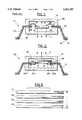
- FIG. 1is a schematic sectional view of an electronic device known in the prior art
- FIG. 2is a schematic sectional view of an electronic device incorporating features of the present invention
- FIG. 3is a diagrammatical sectional illustration of various layers in the interposer of the electronic device shown in FIG. 2;
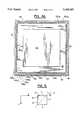
- FIG. 4Ais a plan bottom view of the interposer of the electronic device shown in FIG. 2 showing a first layer having wirebound pads;
- FIG. 4Bis a schematic bottom view of the interposer as in FIG. 4A with a cut away section showing a second layer redistribution traces or circuits;
- FIG. 4Cis a schematic bottom view of the interposer as in FIG. 4A with a cut away section showing a third layer forming a ground layer;
- FIG. 4Dis a schematic bottom view of the interposer as in FIG. 4A with a cut away section showing a fourth layer having another group of redistribution traces or circuits;
- FIG. 5is a diagrammatic view of how a chip is reoriented or flipped in order to be mounted to the interposer
- FIG. 6is a schematic sectional view of an alternate embodiment of an electronic package incorporating features of the present invention.
- FIG. 7is a schematic sectional view of another alternate embodiment of the present invention.
- the package 10generally comprises an electronic component 12, a lead frame 14a and a casing 16.
- the component 12is a semiconductor chip with electrical connection areas on a top side 18.
- Wires 20have first ends 22 bonded to the electrical connection areas on the top side 18 of the chip 12.
- Second ends 24 of the wires 20are bonded to electrical connection pads 26 on an interior edge 28 of the lead frame 14a.
- the lead frame 14ahas conductive leads 30 that extend to its outer bottom edge 32 with pads 34 for connection to an electronic device (not shown).
- the casing 16is made of metal, is attached to the lead frame 14a, and surrounds the chip 12 and wires 20.
- the casing 16has a base 36 and a cover 38.
- the chip 12has a thermal path of heat dissipation in a downward direction, as shown by lines H. This is known as a cavity up configuration.
- Another type of electronic packageis known with the same type of lead frame and casing, but housing a different chip (not shown) with connection pads on its bottom side with a thermal path of heat dissipation in an upward direction. This is known as a cavity down configuration. In order to provide both cavity up and cavity down configurations, a manufacturer needs two different types of chips.
- the package 40includes the chip 12, a lead frame 14, the casing 16, and a redistribution interposer 42.
- the interposer 42is preferably comprised of ceramic material with multiple layers of conductive material. Referring also to FIG. 3, in the embodiment shown, the interposer 42 has four layers 44, 45, 46, 47 of conductive material.
- the first layer 44is a wirebond layer located on the bottom side 48 of the interposer 42.
- the second layer 45is a first group of redistribution leads or traces.
- the third layer 46is a ground layer.
- the fourth layer 47is a second group of redistribution leads or traces.
- the wirebond layer 44 on the bottom side 48 of the interposer 42is shown.
- the bottom of the chip 12is directly attached to the bottom side 48 of the interposer 42 in center area 50 as will be described below.
- Located around the perimeter of the bottom side 48are two groups of electrical connection pads 52.
- the first group 52a of pads 52are electrically connected to the chip 12 by wires 20a.
- the second group 52b of pads 52are electrically connected to the pads 26 of the lead frame 14 by wires 20b.
- FIG. 4Ba schematic bottom view of the interposer is shown with a cut-away section showing a portion of the first group of redistribution leads 54 in the second layer 45.
- the first group of leads 54extend in a general diagonal direction from a first side 56 to a second adjacent side 57 and a third side 58 to a fourth adjacent side 59 of the interposer 42.
- the first group of leads 54all lie in the same plane.
- First ends 60 of some of the these leads 54are individually connected to the first pads 52a 1 on the first side 56 and first pads 52a 3 on the third side 58 by a first group of interplane conductors 62.
- Opposite second ends 64 of these leads 54are individually connected to the second pads 52b 2 on the second side 57 and second pads 52b 4 on the fourth side 59 by a second group of interplane conductors 66.
- First ends 61 of the rest of the leads 54are individually connected to the first pads 52a 2 on the second side 57 and first pads 52a 4 on the fourth side 59 by the first group of interplane conductors 62.
- Opposite second ends 65 of these remaining leads 54are individually connected to the second pads 52b 1 on the first side of the second pads 52b 3 on the third side 58 by the second group of interplane conductors 66.
- first pads 52a 1 on the first side 56are connected to second pads 52b 2 on the second side 57
- first pads 52a 3 on the third side 58are connected to second pads 52b 4 on the fourth side 59
- first pads 52a 2 on the second side 57are connected to second pads 52b 1 on the first side 56
- first pads 52a 4 on the fourth side 59are connected to second pads 52b 3 on the third side 58.
- FIG. 4Ca schematic bottom view of the interposer 42 is shown with a cut-away section showing a portion of the ground 68 in the third layer 46.
- the ground 68in the embodiment shown, has a first section 70 and a second section 72.
- a gap 74is provided between the two sections 70, 72. In alternate embodiments no ground section need be provided, or only one ground section, or more than two ground sections could be provided.
- the first and second ground sections 70, 72lie in the same plane.
- the first section 70is connected to ground pads 52a g and 52b g of both the first and second pads 52a and 52b on all four sides 56-59 by conductive traces 76 and a third group of interplane conductors 78.
- FIG. 4Da schematic bottom view of the interposer 42 is shown with a cut-away section showing a portion of the second group of redistribution leads 80 in the fourth layer 47.
- the leads 80function the same as leads 54.
- a fourth group 82 of interplane conductorsconnect first ends 84 of the leads 80 to first pads 52a on the wirebond layer 44 and second ends 86 to second pads 52b on the wirebond layer 44.
- the fourth layer 47also comprises ground traces 88.
- a fifth group 90 of interplane conductorsconnect the traces 88 to some of the ground pads 52a g and 52b g .
- a sixth group 92 of interplane conductorsconnect the traces 88 to the second section 72 of the ground 68 in the third layer 46.
- the chip 12is mounted to the bottom side 48 of the interposer in center area 50.
- the chip 12is mounted in a flipped or upsidedown orientation relative to its normal orientation in the cavity up configuration shown in FIG. 1.
- the orientation of the chip 12is flipped on a diagonal as illustrated in FIG. 5. Because of this diagonal flip F from the chip's normal orientation shown in FIG. 1, connection areas or pads 21 which formerly faced an upward direction will now be located in a downward direction.
- the connection pads 21 on the chip 12will be diagonally reversed. In other words, pads formerly on side A will now be on side B, pads formerly on side B will now be on side A, pads formerly on side C will now be on side D, and pads formerly on side D will now be on side C.
- the redistribution interposer 42uses its redistribution leads 54 and 80 to correct for the diagonal reversal. If the diagonal reversal was not corrected for, the lead frame 14 would connect the pads 21 of the chip to the wrong contact areas of the electronic device (not shown) that the package 40 is connected to. Use of the interposer 42 has been found to be the most effective means for connecting for the diagonal reversal.
- a single chip 12can be used for both cavity up and cavity down oriented packages.
- the electronic device (not shown)does not need to be redesigned.
- the lead frame 14does not need to be redesigned.
- the size of the package 40is the same size as the package 10.
- the pads 21are wirebonded to pads 52a by wires 20a.
- the pads 52bare wirebonded to pads 26 of the lead frame 14 by wires 20b.
- the wires 20bstructurally support the interposer 42 and chip 12 on the lead frame 14.
- the casing 16is then attached to the lead frame 14 to enclose the chip 12, interposer 42, and wires 20a, 20b.
- the interposer 110is joined to a lead frame pad 43 (see FIG. 7) prior to joining of the chip 12 on the interposer.
- a pad 21 of the chip 12is connected to the lead frame 14 by a pad 52b located at an opposite diagonal side of the chip 12 than the pad 21.
- the interposer 42corrects for the diagonal flip of the chip 12 in order for the correct pad 21 of the chip 12 to be connected to the correct pad 26 of the lead frame 14.
- a redistribution interposercould be designed to receive multiple chips to form a multi-chip module (MCM).
- MCMmulti-chip module
- the interposer of the present inventioncan also be used with new chips that are designed smaller than chip 12 to reduce the bond pad pitch to less than can be accomplished on a lead frame.
- the pads on two of the sideswould be reoriented 180° rather than 90°, and the traces on the interposer would be designed to compensate for this reorientation.
- the pads on the other two sideswould remain on the same pre-flip side, but would be reoriented 180° on that same side.
- the traces on the interposerwould also be designed to compensate for this type of reorientation.
- the electronic package 100has the chip 12, the lead frame 14, base 36, wires 20a, 20b, and an interposer 102.
- the interposer 102is suitably sized and shaped to form a cover for the package 100.
- the interposer 102is structurally connected to the lead frame 14 at its perimeter at area 104.
- the lead frame 14ahas a lead frame pad 43.
- the interposer 110is mounted to the lead frame pad 43.
- the chip 12also mounted to the lead frame pad 43.
- the interposer 110has a general ring shape with the chip 12 located inside its center aperture. Wires 20a, 20b electrically connected the chip 12 to the interposer 110 and the interposer 110 to the electrical pads of the lead frame 14a, respectively.
Landscapes
- Physics & Mathematics (AREA)
- Condensed Matter Physics & Semiconductors (AREA)
- General Physics & Mathematics (AREA)
- Engineering & Computer Science (AREA)
- Computer Hardware Design (AREA)
- Microelectronics & Electronic Packaging (AREA)
- Power Engineering (AREA)
- Lead Frames For Integrated Circuits (AREA)
Abstract
Description
Claims (24)
Priority Applications (1)
| Application Number | Priority Date | Filing Date | Title |
|---|---|---|---|
| US08/276,564US5455387A (en) | 1994-07-18 | 1994-07-18 | Semiconductor package with chip redistribution interposer |
Applications Claiming Priority (1)
| Application Number | Priority Date | Filing Date | Title |
|---|---|---|---|
| US08/276,564US5455387A (en) | 1994-07-18 | 1994-07-18 | Semiconductor package with chip redistribution interposer |
Publications (1)
| Publication Number | Publication Date |
|---|---|
| US5455387Atrue US5455387A (en) | 1995-10-03 |
Family
ID=23057140
Family Applications (1)
| Application Number | Title | Priority Date | Filing Date |
|---|---|---|---|
| US08/276,564Expired - Fee RelatedUS5455387A (en) | 1994-07-18 | 1994-07-18 | Semiconductor package with chip redistribution interposer |
Country Status (1)
| Country | Link |
|---|---|
| US (1) | US5455387A (en) |
Cited By (18)
| Publication number | Priority date | Publication date | Assignee | Title |
|---|---|---|---|---|
| US6081037A (en)* | 1998-06-22 | 2000-06-27 | Motorola, Inc. | Semiconductor component having a semiconductor chip mounted to a chip mount |
| US6266246B1 (en)* | 1997-11-14 | 2001-07-24 | Silicon Bandwidth, Inc. | Multi-chip module having interconnect dies |
| US6320754B1 (en)* | 1999-08-06 | 2001-11-20 | Agilent Technologies, Inc. | Apparatus for the reduction of interfacial stress caused by differential thermal expansion in an integrated circuit package |
| US6362087B1 (en) | 2000-05-05 | 2002-03-26 | Aptos Corporation | Method for fabricating a microelectronic fabrication having formed therein a redistribution structure |
| US6404046B1 (en) | 2000-02-03 | 2002-06-11 | Amkor Technology, Inc. | Module of stacked integrated circuit packages including an interposer |
| US6424031B1 (en) | 2000-05-08 | 2002-07-23 | Amkor Technology, Inc. | Stackable package with heat sink |
| US6511901B1 (en) | 1999-11-05 | 2003-01-28 | Atmel Corporation | Metal redistribution layer having solderable pads and wire bondable pads |
| US6518659B1 (en) | 2000-05-08 | 2003-02-11 | Amkor Technology, Inc. | Stackable package having a cavity and a lid for an electronic device |
| US6548893B1 (en)* | 2001-07-03 | 2003-04-15 | Bigbear Networks, Inc. | Apparatus and method for hermetically sealing and EMI shielding integrated circuits for high speed electronic packages |
| US6552416B1 (en) | 2000-09-08 | 2003-04-22 | Amkor Technology, Inc. | Multiple die lead frame package with enhanced die-to-die interconnect routing using internal lead trace wiring |
| US6603072B1 (en) | 2001-04-06 | 2003-08-05 | Amkor Technology, Inc. | Making leadframe semiconductor packages with stacked dies and interconnecting interposer |
| US6667544B1 (en) | 2000-06-30 | 2003-12-23 | Amkor Technology, Inc. | Stackable package having clips for fastening package and tool for opening clips |
| US6747341B2 (en)* | 2002-06-27 | 2004-06-08 | Semiconductor Components Industries, L.L.C. | Integrated circuit and laminated leadframe package |
| US6791166B1 (en) | 2001-04-09 | 2004-09-14 | Amkor Technology, Inc. | Stackable lead frame package using exposed internal lead traces |
| US6977431B1 (en) | 2003-11-05 | 2005-12-20 | Amkor Technology, Inc. | Stackable semiconductor package and manufacturing method thereof |
| US20060214284A1 (en)* | 2005-03-24 | 2006-09-28 | Stuart Haden | Apparatus and method for data capture |
| US11145574B2 (en) | 2018-10-30 | 2021-10-12 | Microchip Technology Incorporated | Semiconductor device packages with electrical routing improvements and related methods |
| US20220059465A1 (en)* | 2020-08-20 | 2022-02-24 | International Business Machines Corporation | Combined backing plate and housing for use in bump bonded chip assembly |
Citations (31)
| Publication number | Priority date | Publication date | Assignee | Title |
|---|---|---|---|---|
| US4461924A (en)* | 1982-01-21 | 1984-07-24 | Olin Corporation | Semiconductor casing |
| US4480013A (en)* | 1981-07-20 | 1984-10-30 | Sumitomo Electric Industries, Ltd. | Substrate for use in semiconductor apparatus |
| US4618739A (en)* | 1985-05-20 | 1986-10-21 | General Electric Company | Plastic chip carrier package |
| US4630172A (en)* | 1983-03-09 | 1986-12-16 | Printed Circuits International | Semiconductor chip carrier package with a heat sink |
| US4631820A (en)* | 1984-08-23 | 1986-12-30 | Canon Kabushiki Kaisha | Mounting assembly and mounting method for an electronic component |
| US4677526A (en)* | 1984-03-01 | 1987-06-30 | Augat Inc. | Plastic pin grid array chip carrier |
| US4750092A (en)* | 1985-11-20 | 1988-06-07 | Kollmorgen Technologies Corporation | Interconnection package suitable for electronic devices and methods for producing same |
| US4754317A (en)* | 1986-04-28 | 1988-06-28 | Monolithic Memories, Inc. | Integrated circuit die-to-lead frame interconnection assembly and method |
| US4771330A (en)* | 1987-05-13 | 1988-09-13 | Lsi Logic Corporation | Wire bonds and electrical contacts of an integrated circuit device |
| US4774635A (en)* | 1986-05-27 | 1988-09-27 | American Telephone And Telegraph Company At&T Bell Laboratories | Semiconductor package with high density I/O lead connection |
| US4800419A (en)* | 1987-01-28 | 1989-01-24 | Lsi Logic Corporation | Support assembly for integrated circuits |
| US4816426A (en)* | 1987-02-19 | 1989-03-28 | Olin Corporation | Process for manufacturing plastic pin grid arrays and the product produced thereby |
| US4823234A (en)* | 1985-08-16 | 1989-04-18 | Dai-Ichi Seiko Co., Ltd. | Semiconductor device and its manufacture |
| US4888449A (en)* | 1988-01-04 | 1989-12-19 | Olin Corporation | Semiconductor package |
| US4890152A (en)* | 1986-02-14 | 1989-12-26 | Matsushita Electric Works, Ltd. | Plastic molded chip carrier package and method of fabricating the same |
| US4897508A (en)* | 1988-02-10 | 1990-01-30 | Olin Corporation | Metal electronic package |
| US4903114A (en)* | 1985-10-01 | 1990-02-20 | Fujitsu Limited | Resin-molded semiconductor |
| US4939316A (en)* | 1988-10-05 | 1990-07-03 | Olin Corporation | Aluminum alloy semiconductor packages |
| US5013871A (en)* | 1988-02-10 | 1991-05-07 | Olin Corporation | Kit for the assembly of a metal electronic package |
| US5015803A (en)* | 1989-05-31 | 1991-05-14 | Olin Corporation | Thermal performance package for integrated circuit chip |
| US5041696A (en)* | 1988-04-21 | 1991-08-20 | Siemens Aktiengesellschaft | Chip component for fastening to a circuit board, comprising an electrical or electronic function member |
| US5066368A (en)* | 1990-08-17 | 1991-11-19 | Olin Corporation | Process for producing black integrally colored anodized aluminum components |
| US5073521A (en)* | 1989-11-15 | 1991-12-17 | Olin Corporation | Method for housing a tape-bonded electronic device and the package employed |
| US5077595A (en)* | 1990-01-25 | 1991-12-31 | Mitsubishi Denki Kabushiki Kaisha | Semiconductor device |
| US5098864A (en)* | 1989-11-29 | 1992-03-24 | Olin Corporation | Process for manufacturing a metal pin grid array package |
| US5103292A (en)* | 1989-11-29 | 1992-04-07 | Olin Corporation | Metal pin grid array package |
| US5124783A (en)* | 1989-01-30 | 1992-06-23 | Kabushiki Kaisha Toshiba | Semiconductor device having insulating substrate adhered to conductive substrate |
| US5157588A (en)* | 1991-03-30 | 1992-10-20 | Samsung Electronics Co., Ltd. | Semiconductor package and manufacture thereof |
| US5283717A (en)* | 1992-12-04 | 1994-02-01 | Sgs-Thomson Microelectronics, Inc. | Circuit assembly having interposer lead frame |
| US5294826A (en)* | 1993-04-16 | 1994-03-15 | Northern Telecom Limited | Integrated circuit package and assembly thereof for thermal and EMI management |
| US5345106A (en)* | 1990-06-01 | 1994-09-06 | Robert Bosch Gmbh | Electronic circuit component with heat sink mounted on a lead frame |
- 1994
- 1994-07-18USUS08/276,564patent/US5455387A/ennot_activeExpired - Fee Related
Patent Citations (31)
| Publication number | Priority date | Publication date | Assignee | Title |
|---|---|---|---|---|
| US4480013A (en)* | 1981-07-20 | 1984-10-30 | Sumitomo Electric Industries, Ltd. | Substrate for use in semiconductor apparatus |
| US4461924A (en)* | 1982-01-21 | 1984-07-24 | Olin Corporation | Semiconductor casing |
| US4630172A (en)* | 1983-03-09 | 1986-12-16 | Printed Circuits International | Semiconductor chip carrier package with a heat sink |
| US4677526A (en)* | 1984-03-01 | 1987-06-30 | Augat Inc. | Plastic pin grid array chip carrier |
| US4631820A (en)* | 1984-08-23 | 1986-12-30 | Canon Kabushiki Kaisha | Mounting assembly and mounting method for an electronic component |
| US4618739A (en)* | 1985-05-20 | 1986-10-21 | General Electric Company | Plastic chip carrier package |
| US4823234A (en)* | 1985-08-16 | 1989-04-18 | Dai-Ichi Seiko Co., Ltd. | Semiconductor device and its manufacture |
| US4903114A (en)* | 1985-10-01 | 1990-02-20 | Fujitsu Limited | Resin-molded semiconductor |
| US4750092A (en)* | 1985-11-20 | 1988-06-07 | Kollmorgen Technologies Corporation | Interconnection package suitable for electronic devices and methods for producing same |
| US4890152A (en)* | 1986-02-14 | 1989-12-26 | Matsushita Electric Works, Ltd. | Plastic molded chip carrier package and method of fabricating the same |
| US4754317A (en)* | 1986-04-28 | 1988-06-28 | Monolithic Memories, Inc. | Integrated circuit die-to-lead frame interconnection assembly and method |
| US4774635A (en)* | 1986-05-27 | 1988-09-27 | American Telephone And Telegraph Company At&T Bell Laboratories | Semiconductor package with high density I/O lead connection |
| US4800419A (en)* | 1987-01-28 | 1989-01-24 | Lsi Logic Corporation | Support assembly for integrated circuits |
| US4816426A (en)* | 1987-02-19 | 1989-03-28 | Olin Corporation | Process for manufacturing plastic pin grid arrays and the product produced thereby |
| US4771330A (en)* | 1987-05-13 | 1988-09-13 | Lsi Logic Corporation | Wire bonds and electrical contacts of an integrated circuit device |
| US4888449A (en)* | 1988-01-04 | 1989-12-19 | Olin Corporation | Semiconductor package |
| US4897508A (en)* | 1988-02-10 | 1990-01-30 | Olin Corporation | Metal electronic package |
| US5013871A (en)* | 1988-02-10 | 1991-05-07 | Olin Corporation | Kit for the assembly of a metal electronic package |
| US5041696A (en)* | 1988-04-21 | 1991-08-20 | Siemens Aktiengesellschaft | Chip component for fastening to a circuit board, comprising an electrical or electronic function member |
| US4939316A (en)* | 1988-10-05 | 1990-07-03 | Olin Corporation | Aluminum alloy semiconductor packages |
| US5124783A (en)* | 1989-01-30 | 1992-06-23 | Kabushiki Kaisha Toshiba | Semiconductor device having insulating substrate adhered to conductive substrate |
| US5015803A (en)* | 1989-05-31 | 1991-05-14 | Olin Corporation | Thermal performance package for integrated circuit chip |
| US5073521A (en)* | 1989-11-15 | 1991-12-17 | Olin Corporation | Method for housing a tape-bonded electronic device and the package employed |
| US5098864A (en)* | 1989-11-29 | 1992-03-24 | Olin Corporation | Process for manufacturing a metal pin grid array package |
| US5103292A (en)* | 1989-11-29 | 1992-04-07 | Olin Corporation | Metal pin grid array package |
| US5077595A (en)* | 1990-01-25 | 1991-12-31 | Mitsubishi Denki Kabushiki Kaisha | Semiconductor device |
| US5345106A (en)* | 1990-06-01 | 1994-09-06 | Robert Bosch Gmbh | Electronic circuit component with heat sink mounted on a lead frame |
| US5066368A (en)* | 1990-08-17 | 1991-11-19 | Olin Corporation | Process for producing black integrally colored anodized aluminum components |
| US5157588A (en)* | 1991-03-30 | 1992-10-20 | Samsung Electronics Co., Ltd. | Semiconductor package and manufacture thereof |
| US5283717A (en)* | 1992-12-04 | 1994-02-01 | Sgs-Thomson Microelectronics, Inc. | Circuit assembly having interposer lead frame |
| US5294826A (en)* | 1993-04-16 | 1994-03-15 | Northern Telecom Limited | Integrated circuit package and assembly thereof for thermal and EMI management |
Cited By (25)
| Publication number | Priority date | Publication date | Assignee | Title |
|---|---|---|---|---|
| US20020176238A1 (en)* | 1997-11-14 | 2002-11-28 | The Panda Project, Inc. | Multi-chip module having interconnect dies |
| US6266246B1 (en)* | 1997-11-14 | 2001-07-24 | Silicon Bandwidth, Inc. | Multi-chip module having interconnect dies |
| US6081037A (en)* | 1998-06-22 | 2000-06-27 | Motorola, Inc. | Semiconductor component having a semiconductor chip mounted to a chip mount |
| US6320754B1 (en)* | 1999-08-06 | 2001-11-20 | Agilent Technologies, Inc. | Apparatus for the reduction of interfacial stress caused by differential thermal expansion in an integrated circuit package |
| US20030119297A1 (en)* | 1999-11-05 | 2003-06-26 | Lam Ken M. | Metal redistribution layer having solderable pads and wire bondable pads |
| US6511901B1 (en) | 1999-11-05 | 2003-01-28 | Atmel Corporation | Metal redistribution layer having solderable pads and wire bondable pads |
| US6577008B2 (en) | 1999-11-05 | 2003-06-10 | Atmel Corporation | Metal redistribution layer having solderable pads and wire bondable pads |
| US6762117B2 (en)* | 1999-11-05 | 2004-07-13 | Atmel Corporation | Method of fabricating metal redistribution layer having solderable pads and wire bondable pads |
| US6404046B1 (en) | 2000-02-03 | 2002-06-11 | Amkor Technology, Inc. | Module of stacked integrated circuit packages including an interposer |
| US6362087B1 (en) | 2000-05-05 | 2002-03-26 | Aptos Corporation | Method for fabricating a microelectronic fabrication having formed therein a redistribution structure |
| US6518659B1 (en) | 2000-05-08 | 2003-02-11 | Amkor Technology, Inc. | Stackable package having a cavity and a lid for an electronic device |
| US6424031B1 (en) | 2000-05-08 | 2002-07-23 | Amkor Technology, Inc. | Stackable package with heat sink |
| US6667544B1 (en) | 2000-06-30 | 2003-12-23 | Amkor Technology, Inc. | Stackable package having clips for fastening package and tool for opening clips |
| US6552416B1 (en) | 2000-09-08 | 2003-04-22 | Amkor Technology, Inc. | Multiple die lead frame package with enhanced die-to-die interconnect routing using internal lead trace wiring |
| US6603072B1 (en) | 2001-04-06 | 2003-08-05 | Amkor Technology, Inc. | Making leadframe semiconductor packages with stacked dies and interconnecting interposer |
| US6791166B1 (en) | 2001-04-09 | 2004-09-14 | Amkor Technology, Inc. | Stackable lead frame package using exposed internal lead traces |
| US6548893B1 (en)* | 2001-07-03 | 2003-04-15 | Bigbear Networks, Inc. | Apparatus and method for hermetically sealing and EMI shielding integrated circuits for high speed electronic packages |
| US6747341B2 (en)* | 2002-06-27 | 2004-06-08 | Semiconductor Components Industries, L.L.C. | Integrated circuit and laminated leadframe package |
| CN100377351C (en)* | 2002-06-27 | 2008-03-26 | 半导体元件工业有限责任公司 | Integrated circuit and layered lead frame package |
| US6977431B1 (en) | 2003-11-05 | 2005-12-20 | Amkor Technology, Inc. | Stackable semiconductor package and manufacturing method thereof |
| US20060214284A1 (en)* | 2005-03-24 | 2006-09-28 | Stuart Haden | Apparatus and method for data capture |
| US11145574B2 (en) | 2018-10-30 | 2021-10-12 | Microchip Technology Incorporated | Semiconductor device packages with electrical routing improvements and related methods |
| US20220059465A1 (en)* | 2020-08-20 | 2022-02-24 | International Business Machines Corporation | Combined backing plate and housing for use in bump bonded chip assembly |
| US11676903B2 (en)* | 2020-08-20 | 2023-06-13 | International Business Machines Corporation | Combined backing plate and housing for use in bump bonded chip assembly |
| US11804442B2 (en) | 2020-08-20 | 2023-10-31 | International Business Machines Corporation | Combined backing plate and housing for use in bump bonded chip assembly |
Similar Documents
| Publication | Publication Date | Title |
|---|---|---|
| EP0835600B1 (en) | Perimeter matrix ball grid array circuit package with a populated center | |
| US5455387A (en) | Semiconductor package with chip redistribution interposer | |
| US5563446A (en) | Surface mount peripheral leaded and ball grid array package | |
| US5620928A (en) | Ultra thin ball grid array using a flex tape or printed wiring board substrate and method | |
| US7149095B2 (en) | Stacked microelectronic assemblies | |
| US5293067A (en) | Integrated circuit chip carrier | |
| US6501157B1 (en) | Substrate for accepting wire bonded or flip-chip components | |
| US6621156B2 (en) | Semiconductor device having stacked multi chip module structure | |
| US6376914B2 (en) | Dual-die integrated circuit package | |
| US5468994A (en) | High pin count package for semiconductor device | |
| US5903049A (en) | Semiconductor module comprising semiconductor packages | |
| US4949224A (en) | Structure for mounting a semiconductor device | |
| US6975039B2 (en) | Method of forming a ball grid array package | |
| EP0729183A2 (en) | Thin packaging of multi-chip modules with enhanced thermal/power management | |
| US4912603A (en) | High density printed wiring board | |
| US5650660A (en) | Circuit pattern for a ball grid array integrated circuit package | |
| US6163070A (en) | Semiconductor package utilizing a flexible wiring substrate | |
| JPH1056093A (en) | Semiconductor device and electronic device incorporating the semiconductor device | |
| US6495910B1 (en) | Package structure for accommodating thicker semiconductor unit | |
| KR0145641B1 (en) | Semiconductor integrated circuit apparatus | |
| KR100206975B1 (en) | Semiconductor package | |
| JPH0590335A (en) | Semiconductor device | |
| JPH02244753A (en) | Integrated circuit device |
Legal Events
| Date | Code | Title | Description |
|---|---|---|---|
| AS | Assignment | Owner name:CYRIX CORPORATION, TEXAS Free format text:ASSIGNMENT OF ASSIGNORS INTEREST;ASSIGNOR:CROWLEY, SEAN T.;REEL/FRAME:007093/0945 Effective date:19940615 | |
| AS | Assignment | Owner name:INTERNATIONAL BUSINESS MACHINES CORPORATION, NEW Y Free format text:ASSIGNMENT OF ASSIGNORS INTEREST;ASSIGNOR:CAULFIELD, THOMAS;REEL/FRAME:007124/0583 Effective date:19940826 | |
| AS | Assignment | Owner name:OLIN CORPORATION Free format text:ASSIGNMENT OF ASSIGNORS INTEREST;ASSIGNOR:HOFFMAN, PAUL R.;REEL/FRAME:007153/0582 Effective date:19940923 | |
| AS | Assignment | Owner name:INTERNATIONAL BUSINESS MACHINES CORPORATION Free format text:ASSIGNMENT OF ASSIGNORS INTEREST;ASSIGNOR:PRASAD, KESHAV B.;REEL/FRAME:007402/0994 Effective date:19950317 | |
| FEPP | Fee payment procedure | Free format text:PAYOR NUMBER ASSIGNED (ORIGINAL EVENT CODE: ASPN); ENTITY STATUS OF PATENT OWNER: LARGE ENTITY | |
| FEPP | Fee payment procedure | Free format text:PAYER NUMBER DE-ASSIGNED (ORIGINAL EVENT CODE: RMPN); ENTITY STATUS OF PATENT OWNER: LARGE ENTITY | |
| FPAY | Fee payment | Year of fee payment:4 | |
| AS | Assignment | Owner name:ADVANCED TECHNOLOGY INTERCONNECT INCORPORATED, CAL Free format text:ASSIGNMENT OF ASSIGNORS INTEREST;ASSIGNOR:OLIN CORPORATION;REEL/FRAME:009798/0607 Effective date:19990224 | |
| REMI | Maintenance fee reminder mailed | ||
| LAPS | Lapse for failure to pay maintenance fees | ||
| STCH | Information on status: patent discontinuation | Free format text:PATENT EXPIRED DUE TO NONPAYMENT OF MAINTENANCE FEES UNDER 37 CFR 1.362 | |
| FP | Lapsed due to failure to pay maintenance fee | Effective date:20031003 |