US5454839A - Low profile defibrillation catheter - Google Patents
Low profile defibrillation catheterDownload PDFInfo
- Publication number
- US5454839A US5454839AUS07/919,233US91923392AUS5454839AUS 5454839 AUS5454839 AUS 5454839AUS 91923392 AUS91923392 AUS 91923392AUS 5454839 AUS5454839 AUS 5454839A
- Authority
- US
- United States
- Prior art keywords
- electrode
- catheter
- coil
- catheter body
- conductor
- Prior art date
- Legal status (The legal status is an assumption and is not a legal conclusion. Google has not performed a legal analysis and makes no representation as to the accuracy of the status listed.)
- Expired - Lifetime
Links
Images


Classifications
- A—HUMAN NECESSITIES
- A61—MEDICAL OR VETERINARY SCIENCE; HYGIENE
- A61N—ELECTROTHERAPY; MAGNETOTHERAPY; RADIATION THERAPY; ULTRASOUND THERAPY
- A61N1/00—Electrotherapy; Circuits therefor
- A61N1/02—Details
- A61N1/04—Electrodes
- A61N1/05—Electrodes for implantation or insertion into the body, e.g. heart electrode
- A61N1/056—Transvascular endocardial electrode systems
- A61N1/0563—Transvascular endocardial electrode systems specially adapted for defibrillation or cardioversion
Definitions
- the present inventionpertains to a defibrillation device, and more particularly, refers to a low profile defibrillation catheter where the current conductors are utilized as electrodes.
- the implantable defibrillatorrequires the use of electrodes to conduct large currents through the human heart. These have typically been two or more patches stitched to the heart. These are referred to as epicardial-patch electrodes, and require the surgeon to open the chest cavity for placement.
- Electrode coilsare sometimes passed into the heart chambers. These coils are known as transvenous or catheter electrodes. One coil sits just above the right heart in the right atrium (RA) location, and the other lies in the right ventricular apex (RVA).
- RAright atrium
- RVVAright ventricular apex
- the catheter electrodesare often unable to direct sufficient current through enough of the heart muscle. For this reason, a small patch is often inserted just under the skin, on the patient's lower left side. This requires additional, but minimal, surgery.
- This "subcutaneous patch”is not in direct contact with the heart, but allows a current vector starting at a transvenous electrode and going through heart muscle. Thus, the subcutaneous patch assists in directing current through the heart muscle, and hence, in defibrillating the heart.
- the resistancebe low enough to allow the passage of the large current through the heart.
- the second requirementis that the current lines pass through the vast majority of the heart muscle. This requirement is usually met by having sufficient extent to the electrodes and by careful positioning. Thus, the primary opportunity for optimization is in lowering the electrode resistance.
- FIG. 1illustrates a schematic drawing of a patient 10 fitted with a defibrillating system of the prior art consisting of a pulse generator 12 implanted in the abdominal cavity and connected to epicardial-patch electrodes 14 and 16 by electrical-lead harness 18.
- a pulse generator 12implanted in the abdominal cavity and connected to epicardial-patch electrodes 14 and 16 by electrical-lead harness 18.
- FIG. 1illustrates a schematic representation of a defibrillating system of the prior art implanted in the abdominal cavity, and having epicardial-patch electrodes attached directly to the heart;
- FIG. 2illustrates a schematic representation of a defibrillating system of the present invention having an SVC electrode, an RVA electrode and one subcutaneous-patch electrode;
- FIG. 3illustrates a model for estimation of epicardial resistance
- FIG. 4illustrates a model for estimation of epicardial resistance with respect to a cylindrical shell
- FIG. 5illustrates the end view of a model for estimation of epicardial resistance with respect to a cylindrical shell
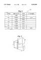
- FIG. 6is a total impedance chart for an electrode system
- FIG. 7illustrates a plan view of the low profile defibrillation catheter
- FIG. 8illustrates a cross-sectional view of the low profile defibrillation catheter.
- FIG. 9is an impedance model for a defibrillator catheter.
- FIG. 2illustrates a schematic drawing of a patient 20 implanted with a defibrillating system including a pectorally implanted pulse generator 22, a subcutaneous-patch electrode 24, and transvenous catheter 26, carrying an SVC electrode 28, and an RVA electrode 30.
- electrode coils 28 and 30are passed into the heart chambers. These coils are known as transvenous or catheter electrodes.
- a coil electrode 28sits just above the right heart in or at the entrance to the right atrium (RA), and the other coil electrode 30 lies in the right ventricular apex (RVA).
- RAright atrium
- RVVAright ventricular apex
- a small subcutaneous-patch electrode 24is inserted just under the skin, on the patient's lower left side. This requires additional, but minimal, surgery.
- This "subcutaneous patch”is not in direct contact with the heart, but allows a current vector starting at a transvenous electrode and going through heart muscle.
- the subcutaneous patch electrode 24assists in directing current through the heart muscle, and hence, in defibrillating the heart.
- the resistancebe low enough to allow the passage of the large current through the heart.
- the second requirementis that the current lines pass through the vast majority of the heart muscle. This requirement is usually met by having electrodes of sufficient extent. Thus, the primary opportunity for optimization is in lowering the electrode resistance.
- the resistance for epicardial electrodescan be estimated by using standard formulas from physics and the dimensions of the epicardial patches.
- This infinitesimal volumeis situated a general, but moveable distance r* from the center of the rod and has an infinitesimal thickness (that is, "gap") dr*.
- Careful inspectionshows that the arc length would be r*W/L and the height L+r*(W-L)/R and multiplied together would be the "area” defined in Eq. 1. So multiplying resistivity p by gap dr*, dividing by "area”, and summing (integrating) the infinitesimal volume from r to R, yields: ##EQU3##
- the catheterpreferably has a maximum diameter of each electrode for a multiple electrode configuration of less than about 10 French (i.e., a maximum diameter ⁇ 3.3 mm) and preferably less than about 6 French (i.e. a maximum diameter ⁇ 2 mm)
- the maximum diameter of the electrodeis less than about 6 French and preferably less than about 4 French.
- the overall length of the electrodeis at least 60 times the radius of the catheter.
- FIGS. 7-8illustrate the details of the construction of the catheter. Note that the conductor is wound continuously to the end of the catheter and is then rewound back over itself to form the actual conductive surface. This is in stark contrast to prior art devices which used different pieces to form the conductor and the electrode. These prior art devices then required crimped or welded connections between the pieces which are a reliability and manufacturability issue, especially if in the areas of highest movement, which are inside the heart itself.
- FIG. 7illustrates a plan view of visible members of the low profile defibrillation catheter 40 including a junction member 42, electrical connectors 44 and 46 extending from the junction member 42, a flexible plastic tubular member 48 extending from the junction member 42, a flexible wound electrode coil member 50 extending from the interior of the flexible plastic tubular member 48, a flexible plastic tubular covering 52 having flared ends 54 and 56 of which flare end 54 accommodates one end of the flexible wound coil electrode member 50, a flexible wound electrode coil member 58 extending from the interior of the flared end 56 and a tined metal catheter tip 60 at the distal end of the flexible wound electrode coil member 58.
- the connector 44is electrically connected to the flexible wound electrode coil member 50 and the connector 46 is electrically connected to the flexible wound electrode coil member 58.
- the flexible wound electrode coil members 50 and 58align coaxially within the flexible tubular member 48 and the flared end member 54 as described in FIG. 8.
- FIG. 8illustrates a cross-sectional view of the major elements of the low profile defibrillation catheter 40 where all numerals correspond to those elements previously described.
- the flexible wound electrode coil 50, a flexible plastic tube 62 and an inner minor radius portion of the flexible wound electrode coil member 58are arranged in a coaxial fashion extending through the flexible tubular member 48 and continuing past the distal end of the flexible tubular member 48 to expose the flexible wound electrode coil member 50 whose distal end secures and terminates suitably within the confines of the flared end 54 of the flexible plastic tubular member 52.
- the flexible wound electrode coil member 58is actually a double layer coil in that it reverses direction at the tined metal catheter tip 60 and is wound back over the flexible plastic tube 62 and ultimately over itself.
- the flexible wound diameter windingwhich is aligned within the confines of the flexible plastic tube 62, as just described, and a major diameter winding which is aligned over and about the outer periphery of the flexible plastic tube 62 and subsequently about itself at a finitely spaced distance.
- the major diameter winding of the flexible wound electrode coil member 58is appropriately terminated between the flexible plastic tube 62 and the flare 56 of the flexible plastic tubular member 52. As illustrated in FIG. 7, it can be seen that the exposure length of the exposed electrode coil wires 50 and 58 is extensive along the length of the low profile defibrillation catheter 40.
Landscapes
- Health & Medical Sciences (AREA)
- Heart & Thoracic Surgery (AREA)
- Cardiology (AREA)
- Nuclear Medicine, Radiotherapy & Molecular Imaging (AREA)
- Engineering & Computer Science (AREA)
- Biomedical Technology (AREA)
- Vascular Medicine (AREA)
- Radiology & Medical Imaging (AREA)
- Life Sciences & Earth Sciences (AREA)
- Animal Behavior & Ethology (AREA)
- General Health & Medical Sciences (AREA)
- Public Health (AREA)
- Veterinary Medicine (AREA)
- Electrotherapy Devices (AREA)
Abstract
Description
Claims (1)
Priority Applications (2)
| Application Number | Priority Date | Filing Date | Title |
|---|---|---|---|
| US07/919,233US5454839A (en) | 1992-07-27 | 1992-07-27 | Low profile defibrillation catheter |
| US08/520,533US5649974A (en) | 1992-07-27 | 1995-08-28 | Low profile defibrillation catheter |
Applications Claiming Priority (1)
| Application Number | Priority Date | Filing Date | Title |
|---|---|---|---|
| US07/919,233US5454839A (en) | 1992-07-27 | 1992-07-27 | Low profile defibrillation catheter |
Related Child Applications (1)
| Application Number | Title | Priority Date | Filing Date |
|---|---|---|---|
| US29821394AContinuation-In-Part | 1992-07-27 | 1994-08-29 |
Publications (1)
| Publication Number | Publication Date |
|---|---|
| US5454839Atrue US5454839A (en) | 1995-10-03 |
Family
ID=25441749
Family Applications (1)
| Application Number | Title | Priority Date | Filing Date |
|---|---|---|---|
| US07/919,233Expired - LifetimeUS5454839A (en) | 1992-07-27 | 1992-07-27 | Low profile defibrillation catheter |
Country Status (1)
| Country | Link |
|---|---|
| US (1) | US5454839A (en) |
Cited By (8)
| Publication number | Priority date | Publication date | Assignee | Title |
|---|---|---|---|---|
| EP0769308A1 (en)* | 1995-10-17 | 1997-04-23 | Pacesetter, Inc. | Implantable pacemaker lead |
| US5713944A (en)* | 1996-02-13 | 1998-02-03 | Angeion Corporation | Cardioversion-defibrillation catheter lead having selectively exposable outer conductors |
| US6535762B1 (en)* | 1999-02-24 | 2003-03-18 | Pacesetter, Inc. | Combination ICD and pacemaker system having integrated distal electrode |
| US20030092303A1 (en)* | 2001-11-09 | 2003-05-15 | Osypka Thomas P. | Multifilar conductor for cardiac leads |
| US20040162600A1 (en)* | 2003-02-14 | 2004-08-19 | Medtronic, Inc. | Reverse wound electrodes |
| US20060265038A1 (en)* | 2005-05-19 | 2006-11-23 | Cvrx, Inc. | Implantable electrode assembly having reverse electrode configuration |
| US20080208118A1 (en)* | 2002-02-01 | 2008-08-28 | Vascular Designs, Inc. | Multi-function catheter and use thereof |
| US20100114021A1 (en)* | 2002-02-01 | 2010-05-06 | Vascular Designs, Inc. | Multi-function catheter and use thereof |
Citations (19)
| Publication number | Priority date | Publication date | Assignee | Title |
|---|---|---|---|---|
| US3614954A (en)* | 1970-02-09 | 1971-10-26 | Medtronic Inc | Electronic standby defibrillator |
| US3942536A (en)* | 1971-03-15 | 1976-03-09 | Mieczyslaw Mirowski | Cardioverting device having single intravascular catheter electrode system and method for its use |
| US4161952A (en)* | 1977-11-01 | 1979-07-24 | Mieczyslaw Mirowski | Wound wire catheter cardioverting electrode |
| US4355646A (en)* | 1980-11-26 | 1982-10-26 | Medtronic, Inc. | Transvenous defibrillating lead |
| US4481953A (en)* | 1981-11-12 | 1984-11-13 | Cordis Corporation | Endocardial lead having helically wound ribbon electrode |
| US4499907A (en)* | 1982-11-15 | 1985-02-19 | Medtronic, Inc. | Energy limiting cardioversion lead |
| US4603705A (en)* | 1984-05-04 | 1986-08-05 | Mieczyslaw Mirowski | Intravascular multiple electrode unitary catheter |
| US4640983A (en)* | 1984-04-09 | 1987-02-03 | Institut Straumann Ag | Conductor device, particularly for at least partial insertion in a human or animal body, comprising a spiral formed from at least one conductor |
| US4718423A (en)* | 1986-10-17 | 1988-01-12 | Spectramed, Inc. | Multiple-function cardiovascular catheter system with very high lumenal efficiency and no crossovers |
| US4922927A (en)* | 1987-12-30 | 1990-05-08 | Intermedics, Inc. | Transvenous defibrillating and pacing lead |
| US4932407A (en)* | 1988-12-15 | 1990-06-12 | Medtronic, Inc. | Endocardial defibrillation electrode system |
| US4974588A (en)* | 1985-06-20 | 1990-12-04 | Medtronic, Inc. | Cardioversion and defibrillation lead system |
| US5007436A (en)* | 1985-06-20 | 1991-04-16 | Medtronic, Inc. | Cardioversion and defibrillation lead system |
| US5115818A (en)* | 1990-02-14 | 1992-05-26 | Medtronic, Inc. | Implantable electrode |
| WO1992009329A1 (en)* | 1990-11-30 | 1992-06-11 | Medtronic, Inc. | Method and apparatus for cardiac defibrillation |
| EP0491979A1 (en)* | 1990-12-22 | 1992-07-01 | Peter Dr. Ing. Osypka | Pacemaker catheter with two poles |
| US5165403A (en)* | 1991-02-26 | 1992-11-24 | Medtronic, Inc. | Difibrillation lead system and method of use |
| US5265623A (en)* | 1992-07-16 | 1993-11-30 | Angeion Corporation | Optimized field defibrillation catheter |
| US5269319A (en)* | 1989-12-08 | 1993-12-14 | Cardiac Pacemakers, Inc. | Unitary intravascular defibrillating catheter with bipolar sensing |
- 1992
- 1992-07-27USUS07/919,233patent/US5454839A/ennot_activeExpired - Lifetime
Patent Citations (20)
| Publication number | Priority date | Publication date | Assignee | Title |
|---|---|---|---|---|
| US3614954A (en)* | 1970-02-09 | 1971-10-26 | Medtronic Inc | Electronic standby defibrillator |
| US3942536A (en)* | 1971-03-15 | 1976-03-09 | Mieczyslaw Mirowski | Cardioverting device having single intravascular catheter electrode system and method for its use |
| US3942536B1 (en)* | 1971-03-15 | 1987-03-24 | ||
| US4161952A (en)* | 1977-11-01 | 1979-07-24 | Mieczyslaw Mirowski | Wound wire catheter cardioverting electrode |
| US4355646A (en)* | 1980-11-26 | 1982-10-26 | Medtronic, Inc. | Transvenous defibrillating lead |
| US4481953A (en)* | 1981-11-12 | 1984-11-13 | Cordis Corporation | Endocardial lead having helically wound ribbon electrode |
| US4499907A (en)* | 1982-11-15 | 1985-02-19 | Medtronic, Inc. | Energy limiting cardioversion lead |
| US4640983A (en)* | 1984-04-09 | 1987-02-03 | Institut Straumann Ag | Conductor device, particularly for at least partial insertion in a human or animal body, comprising a spiral formed from at least one conductor |
| US4603705A (en)* | 1984-05-04 | 1986-08-05 | Mieczyslaw Mirowski | Intravascular multiple electrode unitary catheter |
| US4974588A (en)* | 1985-06-20 | 1990-12-04 | Medtronic, Inc. | Cardioversion and defibrillation lead system |
| US5007436A (en)* | 1985-06-20 | 1991-04-16 | Medtronic, Inc. | Cardioversion and defibrillation lead system |
| US4718423A (en)* | 1986-10-17 | 1988-01-12 | Spectramed, Inc. | Multiple-function cardiovascular catheter system with very high lumenal efficiency and no crossovers |
| US4922927A (en)* | 1987-12-30 | 1990-05-08 | Intermedics, Inc. | Transvenous defibrillating and pacing lead |
| US4932407A (en)* | 1988-12-15 | 1990-06-12 | Medtronic, Inc. | Endocardial defibrillation electrode system |
| US5269319A (en)* | 1989-12-08 | 1993-12-14 | Cardiac Pacemakers, Inc. | Unitary intravascular defibrillating catheter with bipolar sensing |
| US5115818A (en)* | 1990-02-14 | 1992-05-26 | Medtronic, Inc. | Implantable electrode |
| WO1992009329A1 (en)* | 1990-11-30 | 1992-06-11 | Medtronic, Inc. | Method and apparatus for cardiac defibrillation |
| EP0491979A1 (en)* | 1990-12-22 | 1992-07-01 | Peter Dr. Ing. Osypka | Pacemaker catheter with two poles |
| US5165403A (en)* | 1991-02-26 | 1992-11-24 | Medtronic, Inc. | Difibrillation lead system and method of use |
| US5265623A (en)* | 1992-07-16 | 1993-11-30 | Angeion Corporation | Optimized field defibrillation catheter |
Cited By (16)
| Publication number | Priority date | Publication date | Assignee | Title |
|---|---|---|---|---|
| EP0769308A1 (en)* | 1995-10-17 | 1997-04-23 | Pacesetter, Inc. | Implantable pacemaker lead |
| US5713944A (en)* | 1996-02-13 | 1998-02-03 | Angeion Corporation | Cardioversion-defibrillation catheter lead having selectively exposable outer conductors |
| US6535762B1 (en)* | 1999-02-24 | 2003-03-18 | Pacesetter, Inc. | Combination ICD and pacemaker system having integrated distal electrode |
| US20030092303A1 (en)* | 2001-11-09 | 2003-05-15 | Osypka Thomas P. | Multifilar conductor for cardiac leads |
| US6978185B2 (en) | 2001-11-09 | 2005-12-20 | Oscor Inc. | Multifilar conductor for cardiac leads |
| US20080208118A1 (en)* | 2002-02-01 | 2008-08-28 | Vascular Designs, Inc. | Multi-function catheter and use thereof |
| US8251948B2 (en) | 2002-02-01 | 2012-08-28 | Vascular Designs, Inc. | Multi-function catheter and use thereof |
| US8062251B2 (en) | 2002-02-01 | 2011-11-22 | Vascular Designs, Inc. | Multi-function catheter and use thereof |
| US20100114021A1 (en)* | 2002-02-01 | 2010-05-06 | Vascular Designs, Inc. | Multi-function catheter and use thereof |
| US20090182227A1 (en)* | 2002-02-01 | 2009-07-16 | Vascular Designs, Inc. | Multi-function catheter and use thereof |
| US20040162600A1 (en)* | 2003-02-14 | 2004-08-19 | Medtronic, Inc. | Reverse wound electrodes |
| US6920361B2 (en)* | 2003-02-14 | 2005-07-19 | Medtronic, Inc. | Reverse wound electrodes |
| US7395119B2 (en) | 2005-05-19 | 2008-07-01 | Cvrx, Inc. | Implantable electrode assembly having reverse electrode configuration |
| US20080140167A1 (en)* | 2005-05-19 | 2008-06-12 | Cvrx, Inc. | Implantable electrode assembly having reverse electrode configuration |
| US20070276442A1 (en)* | 2005-05-19 | 2007-11-29 | Cvrx, Inc. | Implantable electrode assembly having reverse electrode configuration |
| US20060265038A1 (en)* | 2005-05-19 | 2006-11-23 | Cvrx, Inc. | Implantable electrode assembly having reverse electrode configuration |
Similar Documents
| Publication | Publication Date | Title |
|---|---|---|
| US5649974A (en) | Low profile defibrillation catheter | |
| US4481953A (en) | Endocardial lead having helically wound ribbon electrode | |
| US4355646A (en) | Transvenous defibrillating lead | |
| US5265623A (en) | Optimized field defibrillation catheter | |
| US5342414A (en) | Transvenous defibrillation lead | |
| US8688236B2 (en) | Medical lead coil conductor with spacer element | |
| US3804098A (en) | Body implantable lead | |
| CA1150775A (en) | Trailing tine electrode lead | |
| AU630842B2 (en) | Braid electrode leads and catheters and methods for using the same | |
| US3474791A (en) | Multiple conductor electrode | |
| WO1996006655A1 (en) | Low profile defibrillation catheter | |
| US4444195A (en) | Cardiac lead having multiple ring electrodes | |
| US4499907A (en) | Energy limiting cardioversion lead | |
| US5044375A (en) | Unitary intravascular defibrillating catheter with separate bipolar sensing | |
| US6104961A (en) | Endocardial defibrillation lead with looped cable conductor | |
| US9254380B2 (en) | MRI compatible tachycardia lead | |
| US8326436B2 (en) | Lead including conductors configured for reduced MRI-induced currents | |
| JPH0567310B2 (en) | ||
| DE112010001330T5 (en) | MRI-compatible implantable connection electrode interface | |
| AU2010337309A1 (en) | MRI-conditionally safe medical device lead | |
| JPH09122246A (en) | Ventricle cardioversion of heart or fibrillation removing device | |
| US9504822B2 (en) | Inductive element for providing MRI compatibility in an implantable medical device lead | |
| AU2012333113A1 (en) | Implantable medical device lead including inner coil reverse-wound relative to shocking coil | |
| US5713944A (en) | Cardioversion-defibrillation catheter lead having selectively exposable outer conductors | |
| US5454839A (en) | Low profile defibrillation catheter |
Legal Events
| Date | Code | Title | Description |
|---|---|---|---|
| AS | Assignment | Owner name:ANGEMED, INC., MINNESOTA Free format text:ASSIGNMENT OF ASSIGNORS INTEREST.;ASSIGNORS:ANDERSON, KENNETH M.;KROLL, MARK W.;REEL/FRAME:006256/0783 Effective date:19920723 | |
| AS | Assignment | Owner name:ANGEION CORPORATION, MINNESOTA Free format text:ASSIGNMENT OF ASSIGNORS INTEREST.;ASSIGNOR:ANGEMED, INC.;REEL/FRAME:006451/0596 Effective date:19930204 | |
| STCF | Information on status: patent grant | Free format text:PATENTED CASE | |
| AS | Assignment | Owner name:NORWEST BUSINESS CREDIT, INC., MINNESOTA Free format text:SECURITY INTEREST;ASSIGNOR:ANGEION CORPORATION;REEL/FRAME:009693/0097 Effective date:19990118 | |
| FPAY | Fee payment | Year of fee payment:4 | |
| AS | Assignment | Owner name:ANGEION CORPORATION, MINNESOTA Free format text:RELEASE OF SECURITY INTEREST;ASSIGNOR:NORWEST BUSINESS CREDIT, INC. (N/K/A WELLS FARGO BUSINESS CREDIT, INC.);REEL/FRAME:010470/0293 Effective date:19991202 | |
| AS | Assignment | Owner name:ELA MEDICAL, FRANCE Free format text:ASSIGNMENT OF ASSIGNORS INTEREST;ASSIGNOR:ANGEION CORPORATION;REEL/FRAME:010776/0571 Effective date:20000324 | |
| AS | Assignment | Owner name:ELA MEDICAL S.A., FRANCE Free format text:CONFIRMATORY ASSIGNMENT;ASSIGNOR:AGEION CORPORATION;REEL/FRAME:011763/0662 Effective date:20010409 | |
| FPAY | Fee payment | Year of fee payment:8 | |
| FPAY | Fee payment | Year of fee payment:12 |