US5454824A - Fragmentable ring applier - Google Patents
Fragmentable ring applierDownload PDFInfo
- Publication number
- US5454824A US5454824AUS08/125,382US12538293AUS5454824AUS 5454824 AUS5454824 AUS 5454824AUS 12538293 AUS12538293 AUS 12538293AUS 5454824 AUS5454824 AUS 5454824A
- Authority
- US
- United States
- Prior art keywords
- frame portion
- coring
- tissue
- tissue section
- instrument
- Prior art date
- Legal status (The legal status is an assumption and is not a legal conclusion. Google has not performed a legal analysis and makes no representation as to the accuracy of the status listed.)
- Expired - Lifetime
Links
- 210000000056organAnatomy0.000claimsabstractdescription14
- 230000003872anastomosisEffects0.000claimsabstractdescription8
- 230000033001locomotionEffects0.000claimsdescription14
- 238000005520cutting processMethods0.000claimsdescription10
- 238000013022ventingMethods0.000claimsdescription5
- 230000007246mechanismEffects0.000claimsdescription3
- 230000000903blocking effectEffects0.000claims3
- 230000004913activationEffects0.000claims2
- 230000006835compressionEffects0.000abstractdescription13
- 238000007906compressionMethods0.000abstractdescription13
- 238000003780insertionMethods0.000abstractdescription11
- 230000037431insertionEffects0.000abstractdescription11
- 238000009434installationMethods0.000abstractdescription4
- 210000001072colonAnatomy0.000description5
- 239000000463materialSubstances0.000description5
- 238000000034methodMethods0.000description5
- 230000008878couplingEffects0.000description4
- 238000010168coupling processMethods0.000description4
- 238000005859coupling reactionMethods0.000description4
- 239000002184metalSubstances0.000description3
- 229920004142LEXAN™Polymers0.000description2
- 239000004677NylonSubstances0.000description2
- 230000000712assemblyEffects0.000description2
- 238000000429assemblyMethods0.000description2
- TZCXTZWJZNENPQ-UHFFFAOYSA-Lbarium sulfateChemical compound[Ba+2].[O-]S([O-])(=O)=OTZCXTZWJZNENPQ-UHFFFAOYSA-L0.000description2
- 230000005465channelingEffects0.000description2
- 238000005304joiningMethods0.000description2
- 238000004519manufacturing processMethods0.000description2
- 238000012986modificationMethods0.000description2
- 230000004048modificationEffects0.000description2
- 238000000465mouldingMethods0.000description2
- 229920001778nylonPolymers0.000description2
- 229920000515polycarbonatePolymers0.000description2
- 239000004417polycarbonateSubstances0.000description2
- 229940092690barium sulfateDrugs0.000description1
- 238000001574biopsyMethods0.000description1
- 239000008280bloodSubstances0.000description1
- 210000004369bloodAnatomy0.000description1
- 230000013011matingEffects0.000description1
- 230000017074necrotic cell deathEffects0.000description1
- 230000008439repair processEffects0.000description1
- 239000007787solidSubstances0.000description1
- 210000002784stomachAnatomy0.000description1
- 238000001356surgical procedureMethods0.000description1
Images


Classifications
- A—HUMAN NECESSITIES
- A61—MEDICAL OR VETERINARY SCIENCE; HYGIENE
- A61B—DIAGNOSIS; SURGERY; IDENTIFICATION
- A61B17/00—Surgical instruments, devices or methods
- A61B17/11—Surgical instruments, devices or methods for performing anastomosis; Buttons for anastomosis
- A61B17/115—Staplers for performing anastomosis, e.g. in a single operation
- A61B17/1155—Circular staplers comprising a plurality of staples
- A—HUMAN NECESSITIES
- A61—MEDICAL OR VETERINARY SCIENCE; HYGIENE
- A61B—DIAGNOSIS; SURGERY; IDENTIFICATION
- A61B17/00—Surgical instruments, devices or methods
- A61B17/22—Implements for squeezing-off ulcers or the like on inner organs of the body; Implements for scraping-out cavities of body organs, e.g. bones; for invasive removal or destruction of calculus using mechanical vibrations; for removing obstructions in blood vessels, not otherwise provided for
- A61B2017/22072—Implements for squeezing-off ulcers or the like on inner organs of the body; Implements for scraping-out cavities of body organs, e.g. bones; for invasive removal or destruction of calculus using mechanical vibrations; for removing obstructions in blood vessels, not otherwise provided for with an instrument channel, e.g. for replacing one instrument by the other
Definitions
- the present inventionrelates to surgical instruments used to perform circular anastomosis of tubular tissue sections and, more particularly, to a surgical instrument suitable for installation of multi-ring compression devices for circular anastomosis of tubular tissue sections.
- Some surgical proceduressuch as repair of the colon, require the joining of two rather large sections of tubular tissue. During these procedures, a diseased area of tissue is excised leaving two free ends of healthy tissue to be joined. Some known methods of joining the tissues include stapling or suturing the ends together. A more recent advancement in the art, called a multi-ring compression device, is used to clamp the free ends of the tissue between a series of interlocking rings whose centers are then cut away.
- a multi-ring compression deviceconsists of an outer ring assembly which fits over an intermediary ring. The two rings are then locked together by inserting an inner ring in the intermediary ring which locks in place.
- Still other instrumentssuch as the flexible bronchoscope shown in U.S. Pat. No. 4,880,015 to Nierman, include provisions for insertion of accessory instruments such as biopsy forceps through the instrument in order to access the operative site.
- U.S. Pat. No. 4,817,847 to Redtenbacherdiscloses a circular stapling device having a removable anvil head provided with means to attach an endoscope to the anvil head.
- the ring applier of the present inventionis a novel surgical instrument suitable for insertion and assembly of multi-ring compression devices for circular anastomosis of tubular or hollow organ tissue sections such as, for example, the stomach, colon, etc.
- the instrumentcomprises a body having means to support and align the rings, means for clamping the rings around the free ends of the tissue sections, means for coring away excess clamped tissue and the centers of the rings, separate means for releasing the clamped rings from the instrument and dwell means to delay releasing the rings until after the coring operation is complete.
- the instrumentmay additionally include means for detaching a portion of the support means to facilitate installation and alignment, safety means to ensure safe operation and means for supplying various knife blade profiles.
- the dwell meansconsists of an external cup containing separate and coaxial elements for the channeling means and the releasing means.
- the external cup, channeling and releasing elementsare provided with a series of recesses which, in cooperation with a plurality of shifter keys, act to separate the operations of coring the excess material and ring centers from the separate operation of releasing the assembled and cored rings from the instrument.
- the shifter keysare flexibly affixed to the releasing means.
- the support means for supporting the outer ring assemblyis detachable from the rest of the instrument. By detaching the outer ring and its support, it is more easily placed in a free open end of tubular tissue. The instrument can then be inserted in the opposing open end of tissue and thereafter reattached to the outer ring support means.
- the clamping meansincludes a handle which is rotatable with respect to said support means.
- a cam-clamp having a variable helical depressionis attached to the support means and slidably supported within the handle such that rotation of the handle moves the cam-clamp within the handle.
- the variable helical depression in the cam-clampis initially of a slow rate of twist to provide rapid initial approximation of the rings and of a rapid rate of twist towards the end of the cam-clamp travel to provide slower more precise approximation and increased torque for final clamping of the rings.
- a continuous boreextends longitudinally throughout the length of the instrument to provide a passageway for accessory instruments such as, for example, endoscopes, graspers, cutters and the like.
- lockout meansmay be provided to prevent coring of the tissue sections until they have been clamped.
- Yet another object of the inventionis to provide a safety device to prevent the instrument from being operated prematurely.
- Another object of the inventionis to provide venting means to prevent excessive pressure buildup in the device during clamping of the rings about tissue.
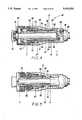
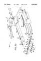
- FIG. 1is an overall perspective view of one embodiment of the present invention
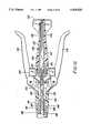
- FIG. 2is an enlarged side detail view of the handle portion of one embodiment of the present invention.
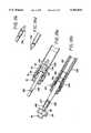
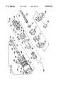
- FIG. 3is an exploded perspective view of one embodiment of the present invention.
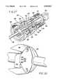
- FIG. 4is an enlarged side detail view of the head portion of the instrument of FIG. 1 showing retraction of an outer ring over an intermediary ring;
- FIG. 5is a similar view thereof showing insertion of an inner locking ring into said intermediary ring
- FIG. 6is a similar view thereof showing the advancement of the coring means through the outer ring
- FIG. 7is a similar view thereof showing the release of the coupling assembly from the present invention.
- FIGS. 8a and 8bare side and top detail views of the shifter keys
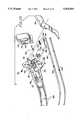
- FIG. 9is a perspective view of a diseased section of the colon being excised and showing a detachable portion of the instrument deployed in a distal section of the colon;
- FIG. 10is a perspective view showing the trocar points pulled through the stapled edges of the tissue
- FIG. 11is a perspective view showing a detachable trocar point being removed by grippers
- FIG. 12is a perspective view showing the detachable assembly being attached to the instrument
- FIG. 13is a perspective view of the colon just prior to clamping the ring assemblies
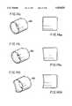
- FIGS. 14a, 14b and 14care views of various knife blade profiles
- FIG. 15is a perspective view showing an alternate double handle embodiment of the present invention.
- FIG. 16is a side detail view of the handle portion of the alternative embodiment
- FIGS. 17a, 17b, 17c and 17dare top and side detail views of one variation of the external cup including associated trocar tip and center rod;
- FIGS. 18a, 18b, 18c and 18dare detail views of other varying external cup portions of the alternative embodiment incorporating another variation of the detachable outer ring support and associated trocar tips;
- FIG. 19a, 19b, 19c, 19d and 19eare detail views of a female outer ring
- FIGS. 20a, 20b, 20c, 20d and 20eare detail views of a male outer ring
- FIGS. 21a, 21b, 21c and 21dare detail views of an intermediate ring
- FIGS. 22a, 22b, 22c and 22dare detail views of an inner ring
- FIG. 23is an exploded perspective view of the alternate embodiment of the invention.
- FIG. 24is a perspective view of another embodiment of the invention.
- FIG. 25is an exploded perspective view of the body portion and retractor portion thereof.
- FIG. 26is an exploded perspective view of the head portion of FIG. 24;
- FIG. 27is a perspective view, partially shown in section, of the head portion
- FIG. 28is a partial plan view of a band attachment means
- FIG. 29is an enlarged exploded view of a lockout mechanism utilized in the device of FIG. 24;
- FIG. 30is a partial side perspective view of the body portion
- FIG. 31is a perspective view, partially shown in section, of the instrument of FIG. 24, illustrating the throughbore;
- FIG. 32is a perspective view, partially shown in section, of the instrument of FIG. 31, with an accessory instrument inserted therethrough;
- FIG. 33is an enlarged side cross-sectional detail view of the head portion of the embodiment of the FIG. 24 showing an outer ring retracted over an intermediary ring;
- FIG. 34is a view similar to FIG. 33 showing insertion of an inner locking ring
- FIG. 35is a view similar to FIG. 34 showing advancement of the coring means through the outer ring.
- FIG. 36is a view similar to FIG. 35 showing the release of the assembled ring assembly from the frame.
- the ring applier 10generally includes a body portion 12, a head portion 14 and a retractor portion 16 extending through body portion 12 and head portion 14.
- An external tube 18joins head portion 14 to body portion 12.
- body portion 12further includes a saddle member 20 having a bore 22 therethrough, an L-shaped handle 24 pivotably mounted on saddle member 20 and having an end 26 extending into bore 22, and a tail member 28 extending outward from saddle member 20.
- Saddle member 20includes a threaded collar 30 slidably disposed within bore 22 and pivotably connected to inward extending end 26 of handle 24 such that movement of handle 24 slides collar 30 within saddle bore 22. It is further contemplated to provide locking springs 44 designed to hold collar 30 at the end of its forward travel.
- Saddle member 20further includes a return spring 46 for biasing collar 30 rearward within saddle bore 22.
- Tail member 28extends outward from saddle member 20 and defines a bore 32 coaxial and communicative with saddle bore 22.
- a clamp knob 34is rotatably suspended at one end 36 of tail member 28 and has a bore 38 coaxial with tail bore 32.
- Knob 34has a threaded base section 40 in which a threaded shaft 42 is slidably suspended within bore 38 and in threaded engagement with knob 34 such that turning knob 34 moves shaft 42 within tail bore 32.
- the multi-ring compression devices used in connection with ring applier 10generally include a plurality of interlocking rings for clamping tissue therebetween.
- these devicesconsist of an outer ring 94 and an intermediary ring 52 between which the tissue is clamped and an inner ring 72 for locking insertion into intermediary ring 52.
- the insertion of the inner ring 72forces outward biased edges of the intermediary ring 52 against inside edges of the outer ring 94 for a press-fit connection.
- an outward facing lip of the inner ring 72locks into place on an annular recess on an inside edge of the intermediary ring 52 thus locking the entire assembly together.
- the outer ring assembly 94consists of a male fragmentable ring 94a (FIGS. 20 (a-e)), having a shoulder 21 on a rim 23 thereof, which fits over a similar female fragmentable ring 94b (FIGS. 19(a-e)).
- Rings 94a and 94bare each molded in two side-by-side halves to facilitate manufacture.
- Each halfincludes a semi-circular central hub 25 to allow capture on one end of ring applier 10. Rather than provide uniform hub thickness thin ribs 27 are incorporated into relatively less thick region of the hub 25.
- the ribs and less thick regionmake it easier for hub 25 to be cut free from the body and ring applier 10 as described hereinbelow.
- the sectional areas of the first ringare offset from the sectional areas of the second ring, the two rings being held together by an overlapping series of projections 29 on ring 94a and recesses 31 on ring 94b.
- the projections 29 on ring 94a and recesses 31 on ring 94bare aligned with the molding plane to facilitate molding.
- the intermediary fragmentable ring 52is fully sectioned and has an annular projection 33 at a base 35 thereof for mounting on ring applier 10. Slots 37 in the base projection facilitates ejection of the ring assembly from ring applier 10.
- the locking inner fragmentable ring 72is also sectioned into four pieces and has male and female sides so the pieces can lock together.
- the preferred versionis more easily molded in the manufacturing process than other known versions and incorporates fillets (internal) and radii (external) on all parts to avoid sharp corners.
- the ringsare formed of a nylon or polycarbonate material such as Lexan®, available from General Electric Corporation. Additionally, it is preferable to form the rings with approximately 3%-15% barium-sulfate to enhance the detectability of the rings by X-rays.
- head portion 14comprises an external cup 48 having a grooved distal end 50 for support of intermediary ring 52 and is threadably engagable with external tube portion 18 at a proximal end 54 of cup 48 thereof.
- External cup 48may be provided with venting means including a plurality of vent holes 49 to allow escape of excess pressure built up during clamping of tissue.
- the venting meansmay be similar to that used in U.S. Pat. No. 4,304,236 to Conta et al., the disclosure of which is incorporated herein by reference.
- External cup 48further includes a plurality of dwell recesses 56 located on an inner surface 58 of external cup 48 and disposed within a restricted bore section 60 of external cup 48.
- a pusher 62 having shifter key channels 64is slidably disposed within an enlarged bore area 66 of external cup 48 and has a circumferential flange 68 at a distal end which abuts a restricted edge 70 of restricted bore section 60.
- Pusher 62slidably supports inner ring 72.
- Knife holder 74having a circumferential flange 76 at a proximal end is slidably disposed within pusher 62. Knife holder 74 further includes a plurality of shifter key recesses 78 on an outer surface 80 and means for support of a circular knife blade 82 affixed to a distal end of knife holder 74. A plurality of shifter keys 84 reside in shifter key channels 64.
- shifter keys 84have a generally trapezoidal cross section along an arcing longitudinal axis. However, one skilled in the art will appreciate that other cross-sectional configurations may be substituted therefor.
- Knife tube 86is coaxial with and slidably supported within external tube 18. (See FIGS. 2 and 3.) Knife tube 86 is threadably engaged with collar 30 at a proximal end and threadably engaged with knife holder 74 at a distal end thereof such that movement of handle 24 causes knife holder 74 to slide within pusher 62 thereby transmitting the movement of handle 24 to pusher 62.
- retractor portion 16includes a clamp rod 88 affixed at a proximal end to a coupling 90 to transmit motion of shaft 42 through tube 18 to coupling 90.
- Coupling 90resides in tail member 28 and is engagable with threaded shaft 42.
- Clamp rod 88has an annular projection 92 at a distal end thereof for carrying outer ring 94.
- Clamp rod 88further includes a threaded retainer 96 to hold outer ring 94 in place against annular projection 92.
- retainer 96 and annular projection 92are located on a center rod 98 which is detachable from said clamp rod 88.
- center rod 98has an annular projection 100 disposed proximally along its length.
- a pointed tip 99At the extreme proximal end of center rod 98 is a pointed tip 99 having a hole 101 therein for attachment of a suture or thread.
- clamp rod 88is hollow at a distal end thereof.
- An annular slot 102is located on an inner surface of clamp rod 88 and is supplied with a plurality of leaf springs 95 biased inward into depression 102 for snap-fit receipt of annular projection 100 on center rod 98.
- a pointed trocar tip 104having a suture or thread retaining hole 97 at a point 91 and an annular projection 93 at a proximal end thereof for snap fit insertion in the annular slot 102 of clamp rod 88.
- a safety button 106is provided on saddle 20 for preventing handle 24 from being prematurely closed.
- the knife blade 82may have several cutting profiles designed to optimize a particular cutting operation.
- the leading edge of the knife blade 82may have a flat shape such as blade 82a (FIG. 14a), a sinusoidal shape such as blade 82b (FIG. 14b) or a hyperbolic shape such as blade 82c (FIG. 14c). It is within the contemplated scope of the invention to use varying knife blade profiles not limited to those shown herein.
- outer ring 94is placed over projection 92 of clamp rod 88.
- Retainer 96is threaded over outer ring 94 securing outer ring 94 to clamp rod 88.
- Inner ring 72is inserted into enlarged area 66 and abuts flange 68 of pusher 62.
- Intermediary ring 52is then press fit into the grooved distal end 50 of external cup 48. In this manner, the ring applier 10 is readied for use.
- the detachable center rod 98 assemblyincluding outer ring 94 and retainer 96, and a trailing suture 103 attached to a hole 101 of center rod tip 99, would have been inserted into a healthy section of tubular or hollow organ tissue and located distally from the diseased tissue as shown in FIG. 9.
- the diseased tissuewould then be excised by known methods.
- One such methodutilizes a separate stapling device to apply several staggered rows of staples to an area of healthy tissue on either side of the diseased tissue and cut and remove the now stapled "packet" of diseased tissue leaving two healthy free ends of tissue stapled closed.
- a small incisionwould then be made to grasp trailing suture 103 and pull pointed tip 99 of center rod 98 through the distal stapled section of tissue.
- tip 104With trocar tip 104 snap fit into place on clamp rod 88, tip 104 would be inserted up to the opposing proximal stapled tissue end and pulled through the staples by a suture 87 affixed to hole 97 in point 91 in the same manner as above, as best seen in FIG. 17a.
- trocar tip 104can then be removed from clamp rod 88 by grippers 105 or other known methods, after which clamp rod 88 is then snap fit over the proximal end of center rod 98 to attach center rod assembly 98 to clamp rod 88 of ring applier 10 FIGS. 12 and 13.
- FIG. 4is stage one showing outer ring 94 fully retracted over intermediary ring 52.
- the free ends of the tissue sections(not shown) would be captured between the rings 52 and 94.
- the center of outer ring 94 and the excess tissueare ready to be cored by knife blade 82.
- pusher 62 and knife holder 74are disposed fully to the rear of external cup 48 and shifter keys 84 reside between shifter key channels 64 in pusher 62 and shifter key recess 78 on knife holder 74.
- the positions of the base of knife holder 74are indicated by reference letter A, the base of the pusher 62 by reference letter B, the forward edge of the knife blade 82 by reference letter C and the position of the shifter keys 84 are indicated by reference letter D.
- handles 24continue to pivot and knife tube 86 advances knife holder 74, independent of pusher 62 which is disengaged from knife holder 74, until rear flanges 76 on the knife holder 74 abut the rear edge of the pusher 62 (reference point B).
- knife holder 74advances knife blade 82 (reference point C) through the captured excess tissue and through the portion of outer ring 94 held by retainer 96 thus fully coring the multi-ring clamp assembly to provide a clear passageway therein.
- shifter keys 84positioned in dwell recess 56 there is nothing to advance the pusher 62 until the end of stage 3 wherein the knife holder flange 76 abuts the rear end of pusher 62.
- the ring assemblymay be of the fragmentable variety to facilitate expulsion. Furthermore, whether of the solid or fragmentable variety, the ring assembly may be partially or wholly formed of degradable or bio-absorbable materials which are degraded or absorbed over time as the tissue heals leaving less or no clamp material to be expelled by the body.
- the preferred materialis nylon or polycarbonate, e.g. Lexan®.
- FIGS. 15 and 23An alternative embodiment of the present invention is illustrated in FIGS. 15 and 23 wherein ring applier 200 generally includes a body portion 202, a head portion 204 and a retractor portion 206 extending through body portion 202 and head portion 204.
- body portion 202is comprised of an elongated front end tube 208, preferably curved, having a bore 210 therein and a wing shaped back end 212 having a bore 214 coaxial with bore 210.
- Body 202includes a pair of handles 216, pivotally and opposingly mounted on body wing 212, having inwardly extending front ends 218 extending into wing bore 214.
- a knife cam 220is slidingly disposed within wing bore 214 and in abutting contact with inwardly extending front ends 218 such that pivoting handles 216 inward forces knife cam 220 forward within wing bore 214.
- Body portion 202further includes a tail member 222, defining a bore 224 coaxial and communicable with wing bore 214, which extends backwards from body wing 212 and is centered between opposing handles 216.
- a barrel 226, defining a bore 228,is rotatably attached to body wing 212 at a first end and is rigidly affixed to tail bore 224 at a second end for rotatable support tail member 222 on body wing 212.
- a cam-clamp 230 having a variable helical depression 232 on an outer surface thereof, and defining a bore 233is rotatably suspended within barrel bore 228.
- the variable helical depression 232 in cam-clamp 230is initially of a slow rate of twist at a proximal end of cam-clamp 230 to provide a rapid initial approximation of rings 52 and 94.
- the helical depression 232changes to a rapid rate of twist to provide slower more precise approximation of rings 52 and 94 and to provide increased torque for clamping rings 52 and 94 around ends of tubular tissue sections.
- a guide tube 234is affixed to wing body 212 at a first end and extends throughbore 233 on cam-clamp 230 into tail bore 224 to guide cam-clamp 230 within tail bore 224.
- a guide pin 236is rigidly affixed to barrel 226 at a proximal end thereof and extends into barrel bore 228 such that a free end of pin 236 engages the helical depression 232 of cam-clamp 230.
- barrel 226drives pin 236 in helical depression 232, thereby drawing cam-clamp 230 along guide rod 234 initially at a fast rate and subsequently in a slower, stronger and more precise fashion.
- approximately 2-5 complete turns of tail member 222is required to approximate rings 52 and 94.
- head portion 204is similar to head portion 14 referred to above and contains the same parts/elements recited therein including pusher 62, knife holder 74, knife blade 82 and shifter keys 84 which function together in exactly the same manner recited hereinabove. Additionally, vent holes 205 (FIGS. 15 and 23) may be provided to prevent the buildup of excess pressures during clamping.
- external cup 48is integral with front end tube 208.
- external cup 48is partially integral with tube 208 and has a threadably detachable front portion 201 to facilitate insertion of the rings.
- FIGS. 17a and bexternal cup 48 is affixed to body tube 208 by a threaded sleeve-head 203 threaded into external cup 48.
- a pair of abutting semicircular guide inserts 238are disposed within tube bore 210 and extend therethrough.
- Each insert 238has a pair of longitudinally extending grooves along each of their respective longitudinal edges such that, when paired in abutting relation to form a complete tube, the inserts 238 define inner 240 and outer 242 pairs of coaxial and longitudinally extending channels in inserts 238.
- Knife bands 244are slidably supported within outer channels 242 and extend therethrough. Knife bands 244 are affixed to knife cam 220 at a proximal end and to knife holder 74 at a distal end such that pivoting handles 216 slides knife holder 74 within pusher 62 thereby transmitting the motion through tube 208.
- retractor portion 206includes a shortened clamp rod 248 extending into external cup 48 at a proximal end thereof and having the leaf-spring snap-fit type of engagement with center rod assembly 98 referred to above in ring applier 10 and is supplied with a similar trocar tip 104, FIG. 17c.
- center rod assembly 98may be partially hollow and have a transverse vent hole 98a to allow excess gas pressure to escape.
- annular projection 250 on clamp rod 248engages an annular depression 252 on center rod 98 for a snap-fit type of engagement similar to that of the first embodiment but without a plurality of leaf springs 95.
- a pair of trocar points 254 and 256 similar to those mentioned aboveare provided for snap-fit connection to clamp rod 248 and annular depression 252 on center rod 98 respectively.
- retractor portion 206further includes a pair of clamp bands 246 slidably suspended within inner channels 240 and attached at distal ends thereof to clamp rod 248.
- Bands 246are affixed to cam-clamp 230 at proximal ends thereof such that turning tail member 222 moves cam-clamp 230 and thus center rod assembly 98 thereby transmitting the motions of cam-clamp 230 through tube 208 to center rod assembly 98.
- ring applier 200is preferably provided with a wing safety 249 rotatably mounted on wing body 212 and positioned between handles 216 such that safety 249 blocks movement of handles 216 in a first position and allows free movement of handles 216 when safety 249 is rotated to a second position.
- ring applier 200is readied and operated in similar fashion to ring applier 10.
- both trocar tips 254 and 256are removed from the surgical field by grippers 105 prior to attaching center rod assembly 98 to clamp rod 248 as shown in FIG. 18b.
- Turning tail member 222analogous to the turning of clamp knob 34 above, draws helical cam-clamp 230 rearward initially a rapid rate to provide quick approximation of rings 52 and 94 and subsequently at a slower rate for more precise approximation of rings 52 and 94. Increased torque accompanies the slower approximation rate to apply a higher clamping force between rings 52 and 94 and the tissue section clamped therebetween.
- Pivoting handles 216is analogous to the pivoting of handle 24 above in that the knife holder 74 is forced forward to initially insert locking inner ring 72 into intermediary ring 52, subsequently core the ring assembly and thereafter finally push the multi-ring assembly and clamped tissue free of ring applier 200.
- ring applier 300generally includes a body portion 302, a head portion 304 and a retractor portion 306 extending through body portion 302 and head portion 304.
- body portion 302is comprised of a pair of body halves 308 which, when combined by alignment pins 309, and fastened together by means of bushing inserts 310 and screws 312, form an elongated front end tube 314, preferably curved, having a cavity 316 therein.
- Body halves 308have wing shaped back ends 318 which, when combined, form a cavity 320 communicable with cavity 316.
- a shrink wrap 322may be provided to aid in holding body halves 308 together and present a smooth outer surface when ring applier 300 is assembled.
- Body portion 302further includes a pair of handles 324, pivotally and opposingly mounted on bushing insert 310, each handle 324 having an inwardly directed front end 326 extending through cavity 320 and into cavity 316.
- a knife cam 328is slidingly disposed within cavity 316 on side grooves 330 formed within body halves 308 and is in abutting contact with inwardly extending front ends 326 of handles 324 such that pivoting handles 324 together forces knife cam 328 forward within cavity 316.
- a knife retractor spring 332is located within body portion 302, and positioned between flange 334 on body halves 308 and knife cam 328, to bias knife cam 328 rearwardly.
- a pair of semicircular guide inserts 336are disposed within tube cavity 316 and extend therethrough.
- Each insert 336has a pair of longitudinally extending projections 338 along each of their respective longitudinal edges such that, when paired in abutting relation to form a complete tube, and positioned within mating body halves 308, define inner 340 and outer 342 pairs of coaxial and longitudinally extending channels, similar to channels 240 and 242 described hereinabove with respect to ring applier 200, in inserts 336.
- head portion 304is similar to head portion 14 referred to above and contains similar parts/elements recited therein including pusher 346 having integral shifter keys 348, knife holder 350 and knife blade 352 which function together in the same manner recited hereinabove.
- head portion 304comprises an external cup 354 having a rear portion 356 and a front portion 358.
- Rear portion 356includes a plurality of flexible fingers 360 at a proximal end and a threaded interior 362.
- a support ring 344(FIG. 25) is provided to hold fingers 360 against body halves 308 thereby securing rear portion 356 to body halves 308.
- Front portion 358has a grooved distal end 364 for support of intermediary ring 52 and is threadably engagable with rear portion 356 of external cup 354 thereof by means of threaded surface 366. As best seen in FIG. 27, front portion 358 forms an enlarged bore area 368 at a distal end and a reduced area portion 370 at a proximal end beneath threaded surface 366. Front portion 358 has a plurality of crosswise support members 372 extending inwardly within enlarged bore area 368. Support members 372 meet within enlarged bore area 368 at a center boss 374 which surrounds a centerline of ring applier 300 to maintain an unobstructed bore therethrough and for support of a knife shield 376 as described hereinbelow.
- Front portion 358 of external cup 354further includes a plurality of dwell recesses 378 located on an inner surface 380 (FIG. 27) of front portion 358 and disposed within a threaded section 366 of front portion 358 to guide shifter keys 348.
- front portion 358 and rear portion 356may be provided with venting means similar to that described in U.S. Pat. No. 4,304,236 to Conta et al. the disclosure of which is incorporated by reference hereinabove, including vent holes 359 (FIGS. 26, 31 and 32).
- Pusher 346(FIG. 26), having resilient means in the form of a pair of flexible arms 382 which terminate in integral shifter keys 348 and having a pair of relatively rigid driving arms 384, is slidably disposed within external cup 354.
- Pusher 346further has a circumferential flange 386 at a distal end which resides in enlarged bore area 368 of external cup 354.
- the longitudinal openings between arms 382 and driving arms 384facilitate sliding pusher 346 around crosswise support members 372.
- Pusher 346slidably supports inner ring 72 within enlarged bore area 368 of external cup 354.
- Knife holder 350has a circumferential flange 388 at a proximal end and is slidably disposed within pusher 346. Knife holder 350 further includes a plurality of support arms 390 having outwardly projecting tabs 392 for engagement with flexible end portions 394 of circular knife blade 352 to affix knife blade 352 to a distal end of knife holder 350. Engagement means in the form of shifter key recesses 396 are formed on an outer surface of two opposing support arms 390. A plurality of longitudinal channels 391 between arms 390 slidably surround support members 372, respectively, and when combined with knife blade 352 serve to limit the travel of the assembled knife blade 352 and holder 350 within external cup 354. Finally knife shield 376 is disposed within knife blade 352 and frictionally engages central boss 374. Knife shield 376 projects past knife blade 352, when knife blade 352 is in a proximalmost position, to protect the user.
- Knife bands 400are affixed to knife cam 328 at a proximal end by means of pins 402 and to knife holder 350 at a distal end by means of pins 404 such that pivoting handles 324 slides knife holder 350 within pusher 346 thereby transmitting the motion of handles 324 through inserts 336 in front end cavity 316.
- knife bands 400aare substituted for knife bands 400 and knife holder 350a is substituted for knife holder 350.
- Ends 406 of knife bands 400aare affixed to knife holder 350a and knife cam 328 by means of flared projections 408 on ends 406 of bands 400 and corresponding notches 410 on knife holder 350a and knife cam 328 as shown in FIG. 28.
- This arrangementeliminates the need for pins 402 and 404 and facilitates maintaining an open channel throughout ring applier 300.
- ring applier 300is preferably provided with a wing safety 412 rotatably mounted on wing shaped back ends 318 and positioned between handles 324 such that safety 412 blocks movement of handles 324 in a first position and allows free movement of handles 324 when safety 412 is rotated to a second position.
- Springs 413are provided between wing safety 412 and wing shaped back end to bias wing safety 412 into the first or locked position.
- retractor portion 306includes a barrel 414, defining a bore 416, and rotatably attached to wing shaped back end 318 at a distal end, which extends backwards from wing shaped back end 318 and is centered between opposing handles 324.
- a tail member 418, defining a bore 420 communicable with wing cavity 320is rigidly affixed to barrel 414 by means of screws 422 at a distal end of barrel 414 for rotatable support of tail member 418 on wing shaped back end 318.
- Flange 424 on barrel 414rotates within grooves 426 (FIG. 29) on body halves 308.
- a cam-clamp 428(FIG. 25) having a variable helical depression 430 on an outer surface thereof, and defining a bore 432 is slidingly suspended within barrel bore 416 by means of a guide tube 434 which is affixed to wing shaped back end 318 at a first end and extends through bore 432 in cam-clamp 428 to guide cam-clamp 428 within barrel bore 416.
- Variable helical depression 430 in cam-clamp 428is initially of a slow rate of twist at a proximal end of cam-clamp 428 to provide a rapid initial approximation of rings 52 and 94.
- the helical depression 430changes to a rapid rate of twist to provide slower more precise approximation of rings 52 and 94 and to provide increased torque for clamping rings 52 and 94 around ends of tubular tissue sections.
- a barrel insert 436is attached to a proximal end of barrel 414 by means of pins 438.
- a guide pin 440is rigidly affixed to barrel insert 436 at a proximal end thereof such that a free end of pin 440 extends into and engages helical depression 430 of cam-clamp 428.
- barrel 414drives pin 440 in helical depression 430, thereby drawing cam-clamp 428 rearwardly along guide tube 434 initially at a fast rate and subsequently in a slower, stronger and more precise fashion.
- retractor portion 306further includes a shortened clamp rod 442 extending into external cup 354 at a proximal end thereof and having slots 444 to allow the tube neck 444a to expand to create a snap-fit type of engagement with a center rod assembly 98 similar to that referred to above in ring applier 10 and is supplied with a similar trocar tip 99.
- retractor portion 306further includes a pair of clamp bands 446 slidably suspended within inner channels 340 and attached at distal ends thereof to clamp rod end 448 (FIG. 26) by insertion of band 446 into slots 450 of clamp rod end 448 and affixed thereto by means of pins 452.
- Bands 446are affixed to cam-clamp 428 at proximal ends thereof by means of pins 454.
- Clamp rod end 448is affixed around clamp rod 442 to connect clamp bands 446 thereto.
- Turning tail member 418moves cam-clamp 428, and thus center rod assembly 98, axially thereby transmitting the motions of cam-clamp 428 through channels 340 to center rod assembly 98.
- clamp bands 446may be connected to clamp rod end 448 and cam-clamp 428 by means of the flared projections/notches system described with respect to knife bands 400 hereinabove.
- Lockout safety 456includes a lock plate 458 slidably supported within plate channel 460 formed in wing shaped back end 318.
- Lock plate 458includes a centrally positioned dog leg shaped engagement leg 462 and a lock tab 464 at a proximal end for engagement with a metal insert 470, which is located in notched area portion 472 of wing safety 412.
- Projection 466is provided at a proximal end of one clamp band 446 to contact and move engagement leg 462.
- a lock spring 468is provided to bias lock plate 458 distally in a locked position. Also included is a display slide 474 and leaf springs 476 disposed between lock plate 458 and wing shaped back end 318 such that slide 474 is visible through window 478 in wing shaped back end 318. An indicator mark 480 on display slide 474 shows through window 478 and indicates when clamp band 446 is fully retracted and ring applier 300 is ready to fire.
- a longitudinal through bore 482extends throughout the length of ring applier 300 to allow accessory instruments such as endoscopes, grasping or cutting forceps, and the like to be inserted into ring applier 300 at a proximal end and be communicable with a distal end of ring applier 300.
- throughbore 482extends through guide tube 434 positioned within tail bore 420 in tail member 418.
- guide tube 434is affixed to wing shaped back end 318 and extends into wing cavity 320.
- a channel 484is formed by paired guide inserts 436, within tube cavity 316 in front end tube 314. Bore 482 continues from wing cavity 420 through channel 484 which is communicable with wing cavity 420.
- knife cam 328must contain a cavity 486 as shown in FIGS. 25 and 31, to allow a continuous communicable passageway through wing cavity 320. Additionally, inwardly directed ends 326 (FIG. 25) of pivotable handles 324 should allow enough clearance around bore 482 so as not to obstruct bore 482.
- bore 482extends on through tube cavity and is coaxial therewith.
- knife holder 350is hollow having a knife bore 488 (FIG. 26) coaxial and communicable with tube cavity 316.
- bore 482continues from channel 484 through tube cavity 316 and on through knife holder 350.
- bore 482extends through and exits out a distal end of clamp rod 442 which is also communicable and coaxial with tube cavity 316.
- bore 482is of circular cross section having a minimum inner diameter on the order of approximately 2 to 6 millimeters and more preferably approximately 5 millimeters.
- An endoscope 490may be inserted through bore 482, as best shown in FIG. 32.
- endoscope 490includes a barrel section 492 which extends through bore 482 and terminates in a lens 494 located at a distal end of barrel section 492.
- ring applier 300is readied and operated in similar fashion to ring applier 10 as shown in FIGS. 9-13.
- trocar tip 104is removed from the surgical field by grippers (FIG. 11) prior to attaching center rod assembly 98 to clamp rod similar to that shown in FIG. 18b hereinabove.
- an endoscopemay be inserted through bore 482, as best shown in FIG. 25.
- Endoscope 490may be used to locate and view the areas of tissue to be joined.
- gripping or cutting devicesmay be inserted through bore 482 to grasp or cut sutures or tissue or the like at the operative site before or after anastomosis.
- Turning tail member 418analogous to the turning of clamp knob 34 above, draws cam-clamp 428 rearward initially a rapid rate to provide quick approximation of rings 52 and 94 and subsequently at a slower rate for more precise approximation of rings 52 and 94. Increased torque accompanies the slower approximation rate to apply a higher clamping force between rings 52 and 94 and the tissue section clamped therebetween.
- lock tab 464is initially biased by spring 468 into engagement with metal insert 470 thereby locking wing safety 412 from rotation.
- projection 466abuts engagement leg 462 moving lock plate 458, and thus lock tab 464, proximally out of engagement with metal insert 470 and into notched area portion 472 of wing safety 412 allowing wing safety 412 to turn freely.
- Indicator mark 480shows through window 478 indicating that cam-clamp 428 is fully retracted and that wing safety 412 is free to rotate thereby unblocking handles 324.
- handles 324is analogous to the pivoting of handles 24 above in that the knife holder 350 is forced forward carrying with it pusher 346 to initially insert locking inner ring 72 into intermediary ring 52.
- shifter keys 348moved within shifter key channels located within the pusher.
- shifter keys 348being integral with flexible arms 382 of pusher 346, are biased into engagement with shifter key recesses 396 in knife holder 350 when in reduced area portion 370 (FIG. 33).
- pusher 346moves with knife holder 350 as handles 324 are pivoted to insert inner ring 72 into intermediary ring 52.
- shifter keys 348flex outwardly (FIG. 34) into enlarged area portion 368 of external cup 354 and out of shifter key recesses 396.
- Disengaging pusher 346 from knife holder 350allows knife blade 352 to advance independently of pusher 346 to core the centers of rings 94 (FIG. 35) and tissue clamped therebetween in a manner similar to that described hereinabove.
- shifter keys 348serve to alternately engage and disengage pusher 346 from knife holder 350 and thus preventing release of the assembled rings prior to completion of coring of the excess tissue.
- flange 388 on knife holder 350abuts driving arms 384 of pusher 346 to finally push assembled rings free from grooved distal end 364 of front portion 358 and thus from ring applier 300 (FIG. 36).
- Knife shield 376projects past a distal end of knife blade 352 when knife blade 352 is in the proximalmost position to protect the user.
Landscapes
- Health & Medical Sciences (AREA)
- Life Sciences & Earth Sciences (AREA)
- Surgery (AREA)
- Heart & Thoracic Surgery (AREA)
- Engineering & Computer Science (AREA)
- Biomedical Technology (AREA)
- Nuclear Medicine, Radiotherapy & Molecular Imaging (AREA)
- Medical Informatics (AREA)
- Molecular Biology (AREA)
- Animal Behavior & Ethology (AREA)
- General Health & Medical Sciences (AREA)
- Public Health (AREA)
- Veterinary Medicine (AREA)
- Surgical Instruments (AREA)
Abstract
Description
This application is a continuation-in-part of prior application Ser. No. 07/959,152, filed Oct. 9, 1992, now U.S. Pat. No. 5,376,098, incorporated herein by reference.
1. Field of the Invention
The present invention relates to surgical instruments used to perform circular anastomosis of tubular tissue sections and, more particularly, to a surgical instrument suitable for installation of multi-ring compression devices for circular anastomosis of tubular tissue sections.
2. Description of Related Art
Some surgical procedures, such as repair of the colon, require the joining of two rather large sections of tubular tissue. During these procedures, a diseased area of tissue is excised leaving two free ends of healthy tissue to be joined. Some known methods of joining the tissues include stapling or suturing the ends together. A more recent advancement in the art, called a multi-ring compression device, is used to clamp the free ends of the tissue between a series of interlocking rings whose centers are then cut away.
Typically, a multi-ring compression device consists of an outer ring assembly which fits over an intermediary ring. The two rings are then locked together by inserting an inner ring in the intermediary ring which locks in place.
In use the free open ends of tissue are captured between the outer ring assembly and the intermediary ring. The entire assembly is then locked together by insertion of the inner ring. The inner core of the ring assembly is then cut away along with any excess tissue. The clamped tissue within the rings is deprived of blood causing necrosis to take place. The outer tissue heals while the necrosised inner tissues and clamps are detached and expelled by the body. Newer clamps or compression rings, such as those shown in U.S. Pat. No. 4,966,602, have a fragmentable structure which enhances the bodies ability to expel the device.
Various surgical instruments have been developed to install the multi-ring compression devices. One known surgical instrument used to install the compression rings is shown in U.S. Pat. No. 4,681,108 to Rosati et al. This instrument generally comprises a cylindrical housing having means for aligning the rings within the tubular tissue sections, driving means for clamping the rings together in locking arrangement around the tissue sections and cutting means for removing excess tissue ends and detaching the instrument from the rings. In the Rosati et al. instrument, the cutting means consists of an advancing circular blade which both cuts the tissue and rings and pushes the rings free of the instrument in one continuous stroke.
Another known instrument for installing multi-ring compression devices is shown in U.S. Pat. No. 4,907,591 to Vasconcellos et al. This instrument includes such features as a rotating cutting blade and locking means to isolate the operation of aligning and clamping the rings from the separate continuous operation of cutting the excess tissue and freeing the instrument from the tissue.
Still other instruments, such as the flexible bronchoscope shown in U.S. Pat. No. 4,880,015 to Nierman, include provisions for insertion of accessory instruments such as biopsy forceps through the instrument in order to access the operative site. U.S. Pat. No. 4,817,847 to Redtenbacher discloses a circular stapling device having a removable anvil head provided with means to attach an endoscope to the anvil head.
The ring applier of the present invention is a novel surgical instrument suitable for insertion and assembly of multi-ring compression devices for circular anastomosis of tubular or hollow organ tissue sections such as, for example, the stomach, colon, etc. The instrument comprises a body having means to support and align the rings, means for clamping the rings around the free ends of the tissue sections, means for coring away excess clamped tissue and the centers of the rings, separate means for releasing the clamped rings from the instrument and dwell means to delay releasing the rings until after the coring operation is complete. The instrument may additionally include means for detaching a portion of the support means to facilitate installation and alignment, safety means to ensure safe operation and means for supplying various knife blade profiles.
In a preferred embodiment of the invention the dwell means consists of an external cup containing separate and coaxial elements for the channeling means and the releasing means. The external cup, channeling and releasing elements are provided with a series of recesses which, in cooperation with a plurality of shifter keys, act to separate the operations of coring the excess material and ring centers from the separate operation of releasing the assembled and cored rings from the instrument. In other embodiments the shifter keys are flexibly affixed to the releasing means.
In another embodiment of the invention the support means for supporting the outer ring assembly is detachable from the rest of the instrument. By detaching the outer ring and its support, it is more easily placed in a free open end of tubular tissue. The instrument can then be inserted in the opposing open end of tissue and thereafter reattached to the outer ring support means.
In a further embodiment of the invention the clamping means includes a handle which is rotatable with respect to said support means. A cam-clamp having a variable helical depression is attached to the support means and slidably supported within the handle such that rotation of the handle moves the cam-clamp within the handle. Preferably the variable helical depression in the cam-clamp is initially of a slow rate of twist to provide rapid initial approximation of the rings and of a rapid rate of twist towards the end of the cam-clamp travel to provide slower more precise approximation and increased torque for final clamping of the rings.
In still another embodiment of the invention a continuous bore extends longitudinally throughout the length of the instrument to provide a passageway for accessory instruments such as, for example, endoscopes, graspers, cutters and the like.
Additionally, lockout means may be provided to prevent coring of the tissue sections until they have been clamped.
Thus it is an object of the present invention to provide a novel surgical instrument capable of delaying the release of an assembled multi-ring compression device until after a coring operation has been completed.
It is a further object of the invention to provide novel means of detaching an outer ring support from the main body of the device to facilitate installation and alignment of the device.
It is a still further object of the invention to provide cutting means having various blade profiles.
Yet another object of the invention is to provide a safety device to prevent the instrument from being operated prematurely.
Another object of the invention is to provide venting means to prevent excessive pressure buildup in the device during clamping of the rings about tissue.
Other novel features and objects of the invention will become evident from the following detailed description of the invention.
Preferred embodiments of the invention are described hereinbelow with reference to the drawings wherein:
FIG. 1 is an overall perspective view of one embodiment of the present invention;
FIG. 2 is an enlarged side detail view of the handle portion of one embodiment of the present invention;
FIG. 3 is an exploded perspective view of one embodiment of the present invention;
FIG. 4 is an enlarged side detail view of the head portion of the instrument of FIG. 1 showing retraction of an outer ring over an intermediary ring;
FIG. 5 is a similar view thereof showing insertion of an inner locking ring into said intermediary ring;
FIG. 6 is a similar view thereof showing the advancement of the coring means through the outer ring;
FIG. 7 is a similar view thereof showing the release of the coupling assembly from the present invention;
FIGS. 8a and 8b are side and top detail views of the shifter keys;
FIG. 9 is a perspective view of a diseased section of the colon being excised and showing a detachable portion of the instrument deployed in a distal section of the colon;
FIG. 10 is a perspective view showing the trocar points pulled through the stapled edges of the tissue;
FIG. 11 is a perspective view showing a detachable trocar point being removed by grippers;
FIG. 12 is a perspective view showing the detachable assembly being attached to the instrument;
FIG. 13 is a perspective view of the colon just prior to clamping the ring assemblies;
FIGS. 14a, 14b and 14c are views of various knife blade profiles;
FIG. 15 is a perspective view showing an alternate double handle embodiment of the present invention;
FIG. 16 is a side detail view of the handle portion of the alternative embodiment;
FIGS. 17a, 17b, 17c and 17d are top and side detail views of one variation of the external cup including associated trocar tip and center rod;
FIGS. 18a, 18b, 18c and 18d are detail views of other varying external cup portions of the alternative embodiment incorporating another variation of the detachable outer ring support and associated trocar tips;
FIG. 19a, 19b, 19c, 19d and 19e are detail views of a female outer ring;
FIGS. 20a, 20b, 20c, 20d and 20e are detail views of a male outer ring;
FIGS. 21a, 21b, 21c and 21d are detail views of an intermediate ring;
FIGS. 22a, 22b, 22c and 22d are detail views of an inner ring;
FIG. 23 is an exploded perspective view of the alternate embodiment of the invention;
FIG. 24 is a perspective view of another embodiment of the invention;
FIG. 25 is an exploded perspective view of the body portion and retractor portion thereof;
FIG. 26 is an exploded perspective view of the head portion of FIG. 24;
FIG. 27 is a perspective view, partially shown in section, of the head portion;
FIG. 28 is a partial plan view of a band attachment means;
FIG. 29 is an enlarged exploded view of a lockout mechanism utilized in the device of FIG. 24;
FIG. 30 is a partial side perspective view of the body portion;
FIG. 31 is a perspective view, partially shown in section, of the instrument of FIG. 24, illustrating the throughbore;
FIG. 32 is a perspective view, partially shown in section, of the instrument of FIG. 31, with an accessory instrument inserted therethrough;
FIG. 33 is an enlarged side cross-sectional detail view of the head portion of the embodiment of the FIG. 24 showing an outer ring retracted over an intermediary ring;
FIG. 34 is a view similar to FIG. 33 showing insertion of an inner locking ring;
FIG. 35 is a view similar to FIG. 34 showing advancement of the coring means through the outer ring; and
FIG. 36 is a view similar to FIG. 35 showing the release of the assembled ring assembly from the frame.
With reference now to the drawings wherein like numerals represent identical parts throughout the several views, and more particularly with reference to FIG. 1, thering applier 10 generally includes a body portion 12, ahead portion 14 and aretractor portion 16 extending through body portion 12 andhead portion 14. Anexternal tube 18 joinshead portion 14 to body portion 12.
As shown in FIG. 2, body portion 12 further includes asaddle member 20 having abore 22 therethrough, an L-shapedhandle 24 pivotably mounted onsaddle member 20 and having anend 26 extending intobore 22, and atail member 28 extending outward fromsaddle member 20.Saddle member 20 includes a threadedcollar 30 slidably disposed withinbore 22 and pivotably connected to inward extendingend 26 ofhandle 24 such that movement ofhandle 24slides collar 30 within saddle bore 22. It is further contemplated to provide lockingsprings 44 designed to holdcollar 30 at the end of its forward travel.Saddle member 20 further includes a return spring 46 for biasingcollar 30 rearward within saddle bore 22.
The multi-ring compression devices used in connection withring applier 10 generally include a plurality of interlocking rings for clamping tissue therebetween. Typically these devices consist of anouter ring 94 and anintermediary ring 52 between which the tissue is clamped and aninner ring 72 for locking insertion intointermediary ring 52. The insertion of theinner ring 72 forces outward biased edges of theintermediary ring 52 against inside edges of theouter ring 94 for a press-fit connection. When theinner ring 72 is fully seated within theintermediary ring 52, an outward facing lip of theinner ring 72 locks into place on an annular recess on an inside edge of theintermediary ring 52 thus locking the entire assembly together.
Turning now to FIGS. 19-22, a preferred embodiment of the multi-ring compression device consists of fragmentable ring assemblies. Theouter ring assembly 94 consists of a malefragmentable ring 94a (FIGS. 20 (a-e)), having ashoulder 21 on arim 23 thereof, which fits over a similar female fragmentable ring 94b (FIGS. 19(a-e)).Rings 94a and 94b are each molded in two side-by-side halves to facilitate manufacture. Each half includes a semi-circularcentral hub 25 to allow capture on one end ofring applier 10. Rather than provide uniform hub thicknessthin ribs 27 are incorporated into relatively less thick region of thehub 25. The ribs and less thick region make it easier forhub 25 to be cut free from the body andring applier 10 as described hereinbelow. The sectional areas of the first ring are offset from the sectional areas of the second ring, the two rings being held together by an overlapping series ofprojections 29 onring 94a and recesses 31 on ring 94b. Preferably, theprojections 29 onring 94a and recesses 31 on ring 94b are aligned with the molding plane to facilitate molding. The intermediaryfragmentable ring 52 is fully sectioned and has anannular projection 33 at abase 35 thereof for mounting onring applier 10.Slots 37 in the base projection facilitates ejection of the ring assembly fromring applier 10. The locking innerfragmentable ring 72 is also sectioned into four pieces and has male and female sides so the pieces can lock together. The preferred version is more easily molded in the manufacturing process than other known versions and incorporates fillets (internal) and radii (external) on all parts to avoid sharp corners. Preferably the rings are formed of a nylon or polycarbonate material such as Lexan®, available from General Electric Corporation. Additionally, it is preferable to form the rings with approximately 3%-15% barium-sulfate to enhance the detectability of the rings by X-rays.
Referring now to FIG. 4head portion 14 comprises anexternal cup 48 having a grooveddistal end 50 for support ofintermediary ring 52 and is threadably engagable withexternal tube portion 18 at a proximal end 54 ofcup 48 thereof.External cup 48 may be provided with venting means including a plurality of vent holes 49 to allow escape of excess pressure built up during clamping of tissue. The venting means may be similar to that used in U.S. Pat. No. 4,304,236 to Conta et al., the disclosure of which is incorporated herein by reference.External cup 48 further includes a plurality of dwell recesses 56 located on aninner surface 58 ofexternal cup 48 and disposed within a restrictedbore section 60 ofexternal cup 48. Apusher 62 having shifterkey channels 64 is slidably disposed within anenlarged bore area 66 ofexternal cup 48 and has acircumferential flange 68 at a distal end which abuts a restrictededge 70 of restrictedbore section 60.Pusher 62 slidably supportsinner ring 72.
Aknife holder 74 having acircumferential flange 76 at a proximal end is slidably disposed withinpusher 62.Knife holder 74 further includes a plurality of shifter key recesses 78 on anouter surface 80 and means for support of acircular knife blade 82 affixed to a distal end ofknife holder 74. A plurality ofshifter keys 84 reside in shifterkey channels 64.
Referring to FIGS. 8a and 8b, in the preferred embodiment,shifter keys 84 have a generally trapezoidal cross section along an arcing longitudinal axis. However, one skilled in the art will appreciate that other cross-sectional configurations may be substituted therefor.
Aknife tube 86 is coaxial with and slidably supported withinexternal tube 18. (See FIGS. 2 and 3.)Knife tube 86 is threadably engaged withcollar 30 at a proximal end and threadably engaged withknife holder 74 at a distal end thereof such that movement ofhandle 24causes knife holder 74 to slide withinpusher 62 thereby transmitting the movement ofhandle 24 topusher 62.
Referring to FIG. 3retractor portion 16 includes aclamp rod 88 affixed at a proximal end to acoupling 90 to transmit motion ofshaft 42 throughtube 18 tocoupling 90.Coupling 90 resides intail member 28 and is engagable with threadedshaft 42.Clamp rod 88 has anannular projection 92 at a distal end thereof for carryingouter ring 94.Clamp rod 88 further includes a threadedretainer 96 to holdouter ring 94 in place againstannular projection 92.
In a preferred embodiment of theinvention retainer 96 andannular projection 92 are located on acenter rod 98 which is detachable from saidclamp rod 88. Referring to FIG. 3,center rod 98 has anannular projection 100 disposed proximally along its length. At the extreme proximal end ofcenter rod 98 is a pointedtip 99 having ahole 101 therein for attachment of a suture or thread. In this preferredembodiment clamp rod 88 is hollow at a distal end thereof. Anannular slot 102 is located on an inner surface ofclamp rod 88 and is supplied with a plurality ofleaf springs 95 biased inward intodepression 102 for snap-fit receipt ofannular projection 100 oncenter rod 98.
Referring to FIGS. 10 and 11, in this embodiment there is also provided apointed trocar tip 104 having a suture orthread retaining hole 97 at apoint 91 and anannular projection 93 at a proximal end thereof for snap fit insertion in theannular slot 102 ofclamp rod 88.
In still a further embodiment of the invention asafety button 106, FIG. 3, is provided onsaddle 20 for preventinghandle 24 from being prematurely closed.
As can be seen in FIGS. 14(a-c) theknife blade 82 may have several cutting profiles designed to optimize a particular cutting operation. In these embodiments the leading edge of theknife blade 82 may have a flat shape such asblade 82a (FIG. 14a), a sinusoidal shape such as blade 82b (FIG. 14b) or a hyperbolic shape such as blade 82c (FIG. 14c). It is within the contemplated scope of the invention to use varying knife blade profiles not limited to those shown herein.
Referring now to FIGS. 2-13 the sequence of operation of the present invention will now be described. In preparingring applier 10 for use,outer ring 94 is placed overprojection 92 ofclamp rod 88.Retainer 96 is threaded overouter ring 94 securingouter ring 94 to clamprod 88.Inner ring 72 is inserted intoenlarged area 66 and abutsflange 68 ofpusher 62.Intermediary ring 52 is then press fit into the grooveddistal end 50 ofexternal cup 48. In this manner, thering applier 10 is readied for use.
In a preferred use of the invention thedetachable center rod 98 assembly includingouter ring 94 andretainer 96, and a trailingsuture 103 attached to ahole 101 ofcenter rod tip 99, would have been inserted into a healthy section of tubular or hollow organ tissue and located distally from the diseased tissue as shown in FIG. 9. As further shown in FIG. 9, the diseased tissue would then be excised by known methods. One such method utilizes a separate stapling device to apply several staggered rows of staples to an area of healthy tissue on either side of the diseased tissue and cut and remove the now stapled "packet" of diseased tissue leaving two healthy free ends of tissue stapled closed.
Referring to FIG. 10, a small incision would then be made to grasp trailingsuture 103 and pull pointedtip 99 ofcenter rod 98 through the distal stapled section of tissue. Withtrocar tip 104 snap fit into place onclamp rod 88,tip 104 would be inserted up to the opposing proximal stapled tissue end and pulled through the staples by asuture 87 affixed to hole 97 inpoint 91 in the same manner as above, as best seen in FIG. 17a.
As shown in FIG. 11,trocar tip 104 can then be removed fromclamp rod 88 bygrippers 105 or other known methods, after which clamprod 88 is then snap fit over the proximal end ofcenter rod 98 to attachcenter rod assembly 98 to clamprod 88 ofring applier 10 FIGS. 12 and 13.
Once the two rods, 88 and 98, have been joined, with the stapled free ends of tubular tissue now located betweenouter ring 94 andintermediary ring 52 theclamp rod 88 is retracted by turning theclamp knob 34 which draws the threadedshaft 42 and thus theclamp rod 88 rearward. Drawingclamp rod 88 rearward pullsouter ring 94 overintermediary ring 52 thus clamping the free ends of the tubular tissue sections betweenrings
The remaining operation can best be easily understood in stages wherein FIG. 4 is stage one showingouter ring 94 fully retracted overintermediary ring 52. The free ends of the tissue sections (not shown) would be captured between therings outer ring 94 and the excess tissue are ready to be cored byknife blade 82. In this stage it can be seen thatpusher 62 andknife holder 74 are disposed fully to the rear ofexternal cup 48 andshifter keys 84 reside between shifterkey channels 64 inpusher 62 and shifterkey recess 78 onknife holder 74. The positions of the base ofknife holder 74 are indicated by reference letter A, the base of thepusher 62 by reference letter B, the forward edge of theknife blade 82 by reference letter C and the position of theshifter keys 84 are indicated by reference letter D.
When thehandles 42 are pivoted inward after the firststage knife tube 86moves pusher 62 andknife holder 74 together as a unit, connected by said shifter keys, forward.Pusher 62 thus movesinner ring 72 forward into locking engagement withintermediary ring 52 at which point (stage 2) theshifter keys 84 are forced out of shifter key recesses 78 and into dwell recesses 56 (Reference point D) due to the angles on the edges ofshifter keys 84 and shifter key recesses 78. As can be seen in FIG. 5, at the end of the second stage the end of pusher 62 (reference point B) and the end of the knife holder 74 (reference point A) are still spaced apart.
Referring to FIG. 6, in stage 3 handles 24 continue to pivot andknife tube 86 advancesknife holder 74, independent ofpusher 62 which is disengaged fromknife holder 74, untilrear flanges 76 on theknife holder 74 abut the rear edge of the pusher 62 (reference point B). During stage 3 advancingknife holder 74 advances knife blade 82 (reference point C) through the captured excess tissue and through the portion ofouter ring 94 held byretainer 96 thus fully coring the multi-ring clamp assembly to provide a clear passageway therein.
It will be noted that withshifter keys 84 positioned indwell recess 56 there is nothing to advance thepusher 62 until the end of stage 3 wherein theknife holder flange 76 abuts the rear end ofpusher 62.
Finally, as can best be seen in FIG. 7 (stage 4) ashandles 24 are pivoted fully closedflange 76 of knife holder 74 (reference point A) is moved forward byknife tube 86 carrying with it pusher 62 (see reference point B).Shifter keys 84 now move forward in dwell recesses 56 allowingpusher 62 to finally push the assembled rings free of theannular holding groove 50 onexternal cup 48. At this point the rings have been fully assembled about the free ends of the tissue sections, excess tissue and the center ofouter ring 94 have been cored out leaving a clear passageway therein and the assembled rings are freed fromring applier 10. Thus the use of the shifter keys and dwell recesses allows the coring operation to be fully complete before the ring assembly is pushed free of the instrument.Ring applier 10 can now be removed. Eventually the clamped tissue will necrotize while the tubular tissue ends heal together. The necrotized tissue and ring assembly will then detach from the healthy tissue and be expelled from the body.
As described above, the ring assembly may be of the fragmentable variety to facilitate expulsion. Furthermore, whether of the solid or fragmentable variety, the ring assembly may be partially or wholly formed of degradable or bio-absorbable materials which are degraded or absorbed over time as the tissue heals leaving less or no clamp material to be expelled by the body. However, as noted above, the preferred material is nylon or polycarbonate, e.g. Lexan®.
An alternative embodiment of the present invention is illustrated in FIGS. 15 and 23 whereinring applier 200 generally includes abody portion 202, ahead portion 204 and aretractor portion 206 extending throughbody portion 202 andhead portion 204.
As shown in FIGS. 15 and 23,body portion 202 is comprised of an elongatedfront end tube 208, preferably curved, having a bore 210 therein and a wing shapedback end 212 having abore 214 coaxial with bore 210.Body 202 includes a pair ofhandles 216, pivotally and opposingly mounted onbody wing 212, having inwardly extending front ends 218 extending intowing bore 214. Aknife cam 220 is slidingly disposed withinwing bore 214 and in abutting contact with inwardly extending front ends 218 such that pivoting handles 216 inwardforces knife cam 220 forward withinwing bore 214.
A cam-clamp 230 having a variablehelical depression 232 on an outer surface thereof, and defining abore 233 is rotatably suspended within barrel bore 228. The variablehelical depression 232 in cam-clamp 230 is initially of a slow rate of twist at a proximal end of cam-clamp 230 to provide a rapid initial approximation ofrings clamp 230 thehelical depression 232 changes to a rapid rate of twist to provide slower more precise approximation ofrings rings
Aguide tube 234 is affixed towing body 212 at a first end and extendsthroughbore 233 on cam-clamp 230 into tail bore 224 to guide cam-clamp 230 withintail bore 224.
Aguide pin 236 is rigidly affixed tobarrel 226 at a proximal end thereof and extends into barrel bore 228 such that a free end ofpin 236 engages thehelical depression 232 of cam-clamp 230. By rotatingtail member 222,barrel 226 drivespin 236 inhelical depression 232, thereby drawing cam-clamp 230 alongguide rod 234 initially at a fast rate and subsequently in a slower, stronger and more precise fashion. Typically, approximately 2-5 complete turns oftail member 222 is required to approximaterings
Referring to FIGS. 17, 18 and 23head portion 204 is similar tohead portion 14 referred to above and contains the same parts/elements recited therein includingpusher 62,knife holder 74,knife blade 82 andshifter keys 84 which function together in exactly the same manner recited hereinabove. Additionally, vent holes 205 (FIGS. 15 and 23) may be provided to prevent the buildup of excess pressures during clamping. As shown in FIG. 18a in one embodiment ofring applier 200external cup 48 is integral withfront end tube 208. In a second embodiment ofring applier 200, FIG. 18b,external cup 48 is partially integral withtube 208 and has a threadably detachablefront portion 201 to facilitate insertion of the rings. In a third embodiment ofring applier 200, FIGS. 17a and b,external cup 48 is affixed tobody tube 208 by a threaded sleeve-head 203 threaded intoexternal cup 48.
As shown in FIGS. 17b, 18b and 23, a pair of abutting semicircular guide inserts 238 are disposed within tube bore 210 and extend therethrough. Eachinsert 238 has a pair of longitudinally extending grooves along each of their respective longitudinal edges such that, when paired in abutting relation to form a complete tube, theinserts 238 define inner 240 and outer 242 pairs of coaxial and longitudinally extending channels ininserts 238.
A pair ofknife bands 244 are slidably supported withinouter channels 242 and extend therethrough.Knife bands 244 are affixed toknife cam 220 at a proximal end and toknife holder 74 at a distal end such that pivoting handles 216 slidesknife holder 74 withinpusher 62 thereby transmitting the motion throughtube 208.
Referring to FIGS. 17a andb retractor portion 206 includes a shortenedclamp rod 248 extending intoexternal cup 48 at a proximal end thereof and having the leaf-spring snap-fit type of engagement withcenter rod assembly 98 referred to above inring applier 10 and is supplied with asimilar trocar tip 104, FIG. 17c.
Furthermore, as shown in FIG. 17d,center rod assembly 98 may be partially hollow and have a transverse vent hole 98a to allow excess gas pressure to escape.
As shown in FIGS. 18a and 18b, in a second embodiment of shortenedclamp rod 248, anannular projection 250 onclamp rod 248 engages anannular depression 252 oncenter rod 98 for a snap-fit type of engagement similar to that of the first embodiment but without a plurality of leaf springs 95. A pair of trocar points 254 and 256 similar to those mentioned above are provided for snap-fit connection to clamprod 248 andannular depression 252 oncenter rod 98 respectively.
Referring to FIGS. 17b,18band 23,retractor portion 206 further includes a pair ofclamp bands 246 slidably suspended withininner channels 240 and attached at distal ends thereof to clamprod 248.Bands 246 are affixed to cam-clamp 230 at proximal ends thereof such that turningtail member 222 moves cam-clamp 230 and thus centerrod assembly 98 thereby transmitting the motions of cam-clamp 230 throughtube 208 to centerrod assembly 98.
Referring to FIGS. 15, 16, and 23ring applier 200 is preferably provided with awing safety 249 rotatably mounted onwing body 212 and positioned betweenhandles 216 such thatsafety 249 blocks movement ofhandles 216 in a first position and allows free movement ofhandles 216 whensafety 249 is rotated to a second position.
In use,ring applier 200 is readied and operated in similar fashion to ringapplier 10. In one embodiment ofring applier 200, aftercenter rod assembly 98 has been deployed in a distal section of tubular tissue, bothtrocar tips grippers 105 prior to attachingcenter rod assembly 98 to clamprod 248 as shown in FIG. 18b.
Turningtail member 222, analogous to the turning ofclamp knob 34 above, draws helical cam-clamp 230 rearward initially a rapid rate to provide quick approximation ofrings rings rings
Pivoting handles 216 is analogous to the pivoting ofhandle 24 above in that theknife holder 74 is forced forward to initially insert lockinginner ring 72 intointermediary ring 52, subsequently core the ring assembly and thereafter finally push the multi-ring assembly and clamped tissue free ofring applier 200.
Another embodiment of the present invention is best illustrated in FIG. 24 whereinring applier 300 generally includes abody portion 302, ahead portion 304 and aretractor portion 306 extending throughbody portion 302 andhead portion 304.
As shown in FIG. 25,body portion 302 is comprised of a pair of body halves 308 which, when combined byalignment pins 309, and fastened together by means of bushing inserts 310 and screws 312, form an elongatedfront end tube 314, preferably curved, having acavity 316 therein. Body halves 308 have wing shaped back ends 318 which, when combined, form acavity 320 communicable withcavity 316. Ashrink wrap 322 may be provided to aid in holdingbody halves 308 together and present a smooth outer surface whenring applier 300 is assembled.Body portion 302 further includes a pair ofhandles 324, pivotally and opposingly mounted onbushing insert 310, each handle 324 having an inwardly directedfront end 326 extending throughcavity 320 and intocavity 316. Aknife cam 328 is slidingly disposed withincavity 316 onside grooves 330 formed within body halves 308 and is in abutting contact with inwardly extending front ends 326 ofhandles 324 such that pivoting handles 324 togetherforces knife cam 328 forward withincavity 316. Aknife retractor spring 332 is located withinbody portion 302, and positioned betweenflange 334 onbody halves 308 andknife cam 328, to biasknife cam 328 rearwardly.
A pair of semicircular guide inserts 336 are disposed withintube cavity 316 and extend therethrough. Eachinsert 336 has a pair of longitudinally extendingprojections 338 along each of their respective longitudinal edges such that, when paired in abutting relation to form a complete tube, and positioned within mating body halves 308, define inner 340 and outer 342 pairs of coaxial and longitudinally extending channels, similar tochannels applier 200, ininserts 336.
Referring to FIGS. 26 and 27head portion 304 is similar tohead portion 14 referred to above and contains similar parts/elements recited therein includingpusher 346 havingintegral shifter keys 348,knife holder 350 andknife blade 352 which function together in the same manner recited hereinabove. Specifically, referring now to FIG. 26head portion 304 comprises anexternal cup 354 having a rear portion 356 and afront portion 358. Rear portion 356 includes a plurality offlexible fingers 360 at a proximal end and a threadedinterior 362. A support ring 344 (FIG. 25) is provided to holdfingers 360 against body halves 308 thereby securing rear portion 356 to body halves 308.
Additionally,front portion 358 and rear portion 356 may be provided with venting means similar to that described in U.S. Pat. No. 4,304,236 to Conta et al. the disclosure of which is incorporated by reference hereinabove, including vent holes 359 (FIGS. 26, 31 and 32).
Pusher 346 (FIG. 26), having resilient means in the form of a pair offlexible arms 382 which terminate inintegral shifter keys 348 and having a pair of relatively rigid drivingarms 384, is slidably disposed withinexternal cup 354.Pusher 346 further has acircumferential flange 386 at a distal end which resides inenlarged bore area 368 ofexternal cup 354. The longitudinal openings betweenarms 382 and drivingarms 384 facilitate slidingpusher 346 around crosswisesupport members 372.Pusher 346 slidably supportsinner ring 72 withinenlarged bore area 368 ofexternal cup 354.
The motion ofhandles 324 is transmitted toknife holder 350 by means of a pair of knife bands 400 (FIG. 25) which are slidably supported within outer channels 342 and extend therethrough.Knife bands 400 are affixed toknife cam 328 at a proximal end by means ofpins 402 and toknife holder 350 at a distal end by means ofpins 404 such that pivoting handles 324 slidesknife holder 350 withinpusher 346 thereby transmitting the motion ofhandles 324 throughinserts 336 infront end cavity 316.
In an alternate embodiment,knife bands 400a are substituted forknife bands 400 andknife holder 350a is substituted forknife holder 350.Ends 406 ofknife bands 400a are affixed toknife holder 350a andknife cam 328 by means of flaredprojections 408 onends 406 ofbands 400 andcorresponding notches 410 onknife holder 350a andknife cam 328 as shown in FIG. 28. This arrangement eliminates the need forpins ring applier 300.
Referring to FIGS. 25, 29 and 30,ring applier 300 is preferably provided with awing safety 412 rotatably mounted on wing shaped back ends 318 and positioned betweenhandles 324 such thatsafety 412 blocks movement ofhandles 324 in a first position and allows free movement ofhandles 324 whensafety 412 is rotated to a second position.Springs 413 are provided betweenwing safety 412 and wing shaped back end tobias wing safety 412 into the first or locked position.
At a proximal end ofring applier 300, as shown in FIG. 25,retractor portion 306 includes a barrel 414, defining abore 416, and rotatably attached to wing shapedback end 318 at a distal end, which extends backwards from wing shapedback end 318 and is centered between opposing handles 324. Atail member 418, defining abore 420 communicable withwing cavity 320 is rigidly affixed to barrel 414 by means ofscrews 422 at a distal end of barrel 414 for rotatable support oftail member 418 on wing shapedback end 318.Flange 424 on barrel 414 rotates within grooves 426 (FIG. 29) on body halves 308.
A cam-clamp 428 (FIG. 25) having a variablehelical depression 430 on an outer surface thereof, and defining abore 432 is slidingly suspended within barrel bore 416 by means of aguide tube 434 which is affixed to wing shapedback end 318 at a first end and extends throughbore 432 in cam-clamp 428 to guide cam-clamp 428 within barrel bore 416. Variablehelical depression 430 in cam-clamp 428 is initially of a slow rate of twist at a proximal end of cam-clamp 428 to provide a rapid initial approximation ofrings clamp 428 thehelical depression 430 changes to a rapid rate of twist to provide slower more precise approximation ofrings rings
Abarrel insert 436 is attached to a proximal end of barrel 414 by means ofpins 438. Aguide pin 440 is rigidly affixed to barrel insert 436 at a proximal end thereof such that a free end ofpin 440 extends into and engageshelical depression 430 of cam-clamp 428. By rotatingtail member 418, barrel 414 drivespin 440 inhelical depression 430, thereby drawing cam-clamp 428 rearwardly alongguide tube 434 initially at a fast rate and subsequently in a slower, stronger and more precise fashion.
Referring again to FIGS. 26 and 27,retractor portion 306 further includes a shortenedclamp rod 442 extending intoexternal cup 354 at a proximal end thereof and having slots 444 to allow the tube neck 444a to expand to create a snap-fit type of engagement with acenter rod assembly 98 similar to that referred to above inring applier 10 and is supplied with asimilar trocar tip 99.
As shown in FIG. 25,retractor portion 306 further includes a pair ofclamp bands 446 slidably suspended withininner channels 340 and attached at distal ends thereof to clamp rod end 448 (FIG. 26) by insertion ofband 446 intoslots 450 ofclamp rod end 448 and affixed thereto by means ofpins 452.Bands 446 are affixed to cam-clamp 428 at proximal ends thereof by means ofpins 454.Clamp rod end 448 is affixed aroundclamp rod 442 to connectclamp bands 446 thereto. Turningtail member 418 moves cam-clamp 428, and thus centerrod assembly 98, axially thereby transmitting the motions of cam-clamp 428 throughchannels 340 to centerrod assembly 98. Alternatively, clampbands 446 may be connected to clamprod end 448 and cam-clamp 428 by means of the flared projections/notches system described with respect toknife bands 400 hereinabove.
A particularly advantageous feature ofring applier 300, as shown in FIGS. 29 and 30, is lockout means in the form of a lockout safety 456 which prevents turningwing safety 412 unless and untilclamp band 446 is fully retracted. Lockout safety 456 includes alock plate 458 slidably supported withinplate channel 460 formed in wing shapedback end 318.Lock plate 458 includes a centrally positioned dog leg shapedengagement leg 462 and alock tab 464 at a proximal end for engagement with ametal insert 470, which is located in notched area portion 472 ofwing safety 412. Projection 466 is provided at a proximal end of oneclamp band 446 to contact and moveengagement leg 462. Alock spring 468 is provided to biaslock plate 458 distally in a locked position. Also included is adisplay slide 474 and leaf springs 476 disposed betweenlock plate 458 and wing shapedback end 318 such that slide 474 is visible throughwindow 478 in wing shapedback end 318. Anindicator mark 480 ondisplay slide 474 shows throughwindow 478 and indicates whenclamp band 446 is fully retracted andring applier 300 is ready to fire.
In a preferred embodiment ofring applier 300, a longitudinal through bore 482 (FIG. 31) extends throughout the length ofring applier 300 to allow accessory instruments such as endoscopes, grasping or cutting forceps, and the like to be inserted intoring applier 300 at a proximal end and be communicable with a distal end ofring applier 300. As best illustrated in FIGS. 31 and 32, throughbore 482 extends throughguide tube 434 positioned within tail bore 420 intail member 418. As noted above, guidetube 434 is affixed to wing shapedback end 318 and extends intowing cavity 320. Achannel 484 is formed by paired guide inserts 436, withintube cavity 316 infront end tube 314.Bore 482 continues fromwing cavity 420 throughchannel 484 which is communicable withwing cavity 420.
In this embodiment it can be readily appreciated that to maintain anunobstructed bore 482 throughoutring applier 300,knife cam 328 must contain acavity 486 as shown in FIGS. 25 and 31, to allow a continuous communicable passageway throughwing cavity 320. Additionally, inwardly directed ends 326 (FIG. 25) ofpivotable handles 324 should allow enough clearance aroundbore 482 so as not to obstructbore 482.
As shown in FIG. 25, pairedinserts 336, and thus channel 484, terminate withincavity 316 proximally ofhead portion 304. Therefore, bore 482 extends on through tube cavity and is coaxial therewith. In the preferred embodiment,knife holder 350 is hollow having a knife bore 488 (FIG. 26) coaxial and communicable withtube cavity 316. Thus bore 482 continues fromchannel 484 throughtube cavity 316 and on throughknife holder 350. Finally, bore 482 extends through and exits out a distal end ofclamp rod 442 which is also communicable and coaxial withtube cavity 316.
Preferably, bore 482 is of circular cross section having a minimum inner diameter on the order of approximately 2 to 6 millimeters and more preferably approximately 5 millimeters.
Anendoscope 490 may be inserted throughbore 482, as best shown in FIG. 32. Typicallyendoscope 490 includes abarrel section 492 which extends throughbore 482 and terminates in alens 494 located at a distal end ofbarrel section 492.
While the provision of a relatively rigid endoscope has been illustrated with respect to the straight bodied ring applier of FIG. 32, it is within the contemplated scope of the invention to provide curvedbodied ring applier 300 with a relatively flexible endoscope for use therein. And while the provision of a longitudinally extending bore has been described with regard to the present ring applier, it is within the contemplated scope of the invention to provide other surgical instruments with a bore therethrough to provide auxiliary access to the operative site for accessory instruments, such as, for example, endoscopes, graspers, cutters and the like.
In use,ring applier 300 is readied and operated in similar fashion to ringapplier 10 as shown in FIGS. 9-13. In one embodiment ofring applier 300, aftercenter rod assembly 98 has been deployed in a distal section of tubular or hollow organ tissue,trocar tip 104 is removed from the surgical field by grippers (FIG. 11) prior to attachingcenter rod assembly 98 to clamp rod similar to that shown in FIG. 18b hereinabove.
Afterring applier 300 has been inserted into a patient an endoscope may be inserted throughbore 482, as best shown in FIG. 25.Endoscope 490 may be used to locate and view the areas of tissue to be joined. Additionally, gripping or cutting devices may be inserted throughbore 482 to grasp or cut sutures or tissue or the like at the operative site before or after anastomosis.
Turningtail member 418, analogous to the turning ofclamp knob 34 above, draws cam-clamp 428 rearward initially a rapid rate to provide quick approximation ofrings rings rings
In the embodiments with the lockout safety 456,lock tab 464 is initially biased byspring 468 into engagement withmetal insert 470 thereby lockingwing safety 412 from rotation. Whenclamp band 446 is fully drawn rearwardly, projection 466 abutsengagement leg 462 movinglock plate 458, and thus locktab 464, proximally out of engagement withmetal insert 470 and into notched area portion 472 ofwing safety 412 allowingwing safety 412 to turn freely.Indicator mark 480 shows throughwindow 478 indicating that cam-clamp 428 is fully retracted and thatwing safety 412 is free to rotate thereby unblocking handles 324.
The pivoting ofhandles 324 is analogous to the pivoting ofhandles 24 above in that theknife holder 350 is forced forward carrying with it pusher 346 to initially insert lockinginner ring 72 intointermediary ring 52.
However, in the aforementioned embodiments, the shifter keys moved within shifter key channels located within the pusher. Inring applier 300,shifter keys 348, being integral withflexible arms 382 ofpusher 346, are biased into engagement with shifterkey recesses 396 inknife holder 350 when in reduced area portion 370 (FIG. 33). Thuspusher 346 moves withknife holder 350 ashandles 324 are pivoted to insertinner ring 72 intointermediary ring 52. Wheninner ring 72 is fully inserted,shifter keys 348 flex outwardly (FIG. 34) intoenlarged area portion 368 ofexternal cup 354 and out of shifter key recesses 396. Disengagingpusher 346 fromknife holder 350 allowsknife blade 352 to advance independently ofpusher 346 to core the centers of rings 94 (FIG. 35) and tissue clamped therebetween in a manner similar to that described hereinabove. Thusshifter keys 348 serve to alternately engage and disengagepusher 346 fromknife holder 350 and thus preventing release of the assembled rings prior to completion of coring of the excess tissue. After coring,flange 388 onknife holder 350 abuts drivingarms 384 ofpusher 346 to finally push assembled rings free from grooveddistal end 364 offront portion 358 and thus from ring applier 300 (FIG. 36).
As noted above, support members 372 (FIG. 27) serve to limit the travel of knife andpusher 346. Afterhandles 324 are released,spring 332biases knife cam 328 proximally thereby drawingknife blade 352 proximally.Knife shield 376 projects past a distal end ofknife blade 352 whenknife blade 352 is in the proximalmost position to protect the user.
While the invention has been particularly shown and described with reference to the preferred embodiments, it will be understood by those skilled in the art that various modifications and changes in form and detail may be made therein without departing from the scope and spirit of the invention. Accordingly, modifications such as those suggested above, but not limited thereto, are to be considered within the scope of the invention.
Claims (10)
1. A surgical instrument for application of surgical fasteners to a first hollow organ tissue section and a second hollow organ tissue section for anastomosis thereof, said surgical instrument comprising:
a) a frame portion;
b) retraction means slidingly disposed within said frame portion for collecting a first tissue section and a second tissue section to be fastened, said frame portion and said retraction means co-defining a bore extending axially throughout the length of the instrument and sized to receive accessory instruments therethrough;
c) pushing means slidingly disposed within said frame portion for application of at least a first and a second monolithic interlocking surgical fastener to the collected first and second tissue sections;
d) coring means slidingly disposed within said frame portion, and engagable with said pushing means for advancement of said pushing means, for coring excess tissue captured between the collected first and second tissue sections; and
e) resilient means associated with said pushing means for alternately engaging and disengaging said pushing means with said coring means, wherein said resilient means engages said pushing means with said coring means during application of the first and second surgical fasteners and said resilient means disengages said pushing means from said coring means during coring.
2. The surgical instrument as recited in claim 1 wherein said coring means includes a knife assembly, having a blade member at a distalmost end for cutting said excess tissue, said knife assembly having engagement means for engaging said resilient means.
3. The surgical instrument as recited in claim 2 further comprising a knife shield affixed to said frame portion and extending distally of said blade member when said blade member is in a proximalmost position.
4. The surgical instrument as recited in claim 2 further comprising a spring member for biasing said blade member in a proximalmost position.
5. The surgical instrument as recited in claim 1 further comprising lockout means associated with said frame portion for blocking movement of said coring means until the first tissue section and the second tissue section are substantially collected by said retraction means.
6. The surgical instrument as recited in claim 1 further comprising venting means to allow escape of excess air pressure between the collected first and second tissue sections and from within the instrument.
7. A surgical instrument for application of surgical fasteners to a first and a second hollow organ tissue section, said surgical instrument comprising:
a) a frame portion defining a bore extending axially throughout the length of said frame portion and adapted for receipt of accessory instruments therethrough;
b) retracting means slidingly disposed within said frame portion for approximation of a first tissue section and a second tissue section, said retracting means movable between a first position wherein the first and the second tissue sections are substantially spaced apart to a second position wherein the first and the second tissue section are substantially approximated;
c) pushing means slidingly disposed within said frame portion for applying at least a first and a second monolithic interlocking surgical fastener to the approximated first and second tissue sections to fasten the first tissue section to the second tissue section;
d) coring means slidingly disposed within said frame portion, and engagable with said pushing means for advancement of said pushing means, for coring excess tissue captured between the fastened first and second tissue sections;
e) resilient means associated with said pushing means for alternately engaging and disengaging said pushing means with said coring means; and
f) lockout means associated with said frame portion for blocking activation of said pushing means and said coring means until the first and the second tissue sections have been substantially approximated by said retraction means.
8. The surgical instrument as recited in claim 7 further comprising a handle mechanism operatively associated with said frame portion, said lockout means blocking said handle mechanism to prevent activation of said pushing means and said coring means until the first and second tissue sections have been substantially approximated.
9. A surgical instrument for application of surgical fasteners to a first hollow organ tissue section and a second hollow organ tissue section for anastomosis thereof, said surgical instrument comprising:
a) a frame portion;
b) retraction means slidably disposed within said frame portion for collecting a first hollow organ tissue section and a second hollow organ tissue section to be fastened;
c) support means located distally of said frame portion for holding at least one surgical fastener;
d) a tail member rotatably mounted in axial alignment with said frame portion;
e) a handle having a distal end and a proximal end, said handle attached to said frame portion for moving said proximal end of said handle towards said frame portion such that said at least one surgical fastener functionally connects the first and second hollow organ tissue sections; and
f) said frame portion, said tail member and said retraction means co-define a bore extending axially through the length of the instrument and sized to receive accessory instruments therethrough.
10. A surgical instrument for application of surgical fasteners to a first hollow organ tissue section and a second hollow organ tissue section for anastomosis thereof, said surgical instrument comprising:
a) a frame portion;
b) retraction means slidingly disposed within said frame portion for collecting a first tissue section and a second tissue section to be fastened, said frame portion and said retraction means co-defining a bore extending axially therethrough and sized to receive accessory instruments therethrough;
c) pushing means slidingly disposed within said frame portion for application of surgical fasteners to the collected first and second tissue sections;
d) coring means slidingly disposed within said frame portion, and engagable with said pushing means for advancement of said pushing means, for coring excess tissue captured between the collected first and second tissue sections; and
e) resilient means associated with said pushing means for alternately engaging and disengaging said pushing means with said coring means, wherein said resilient means engages said pushing means with said coring means during application of the surgical fasteners and said resilient means disengages said pushing means from said coring means during coring.
Priority Applications (5)
| Application Number | Priority Date | Filing Date | Title |
|---|---|---|---|
| US08/125,382US5454824A (en) | 1992-10-09 | 1993-09-22 | Fragmentable ring applier |
| CA002130954ACA2130954A1 (en) | 1993-09-22 | 1994-08-26 | Fragmentable ring applier |
| DE69407240TDE69407240T2 (en) | 1993-09-22 | 1994-09-21 | Device for attaching fragile rings |
| EP94114886AEP0643946B1 (en) | 1993-09-22 | 1994-09-21 | Fragmentable ring applier |
| ES94114886TES2111820T3 (en) | 1993-09-22 | 1994-09-21 | FRAGMENTABLE RING APPLICATOR. |
Applications Claiming Priority (2)
| Application Number | Priority Date | Filing Date | Title |
|---|---|---|---|
| US07/959,152US5376098A (en) | 1992-10-09 | 1992-10-09 | Fragmentable anastomosis ring applier |
| US08/125,382US5454824A (en) | 1992-10-09 | 1993-09-22 | Fragmentable ring applier |
Related Parent Applications (1)
| Application Number | Title | Priority Date | Filing Date |
|---|---|---|---|
| US07/959,152Continuation-In-PartUS5376098A (en) | 1992-10-09 | 1992-10-09 | Fragmentable anastomosis ring applier |
Publications (1)
| Publication Number | Publication Date |
|---|---|
| US5454824Atrue US5454824A (en) | 1995-10-03 |
Family
ID=22419467
Family Applications (1)
| Application Number | Title | Priority Date | Filing Date |
|---|---|---|---|
| US08/125,382Expired - LifetimeUS5454824A (en) | 1992-10-09 | 1993-09-22 | Fragmentable ring applier |
Country Status (5)
| Country | Link |
|---|---|
| US (1) | US5454824A (en) |
| EP (1) | EP0643946B1 (en) |
| CA (1) | CA2130954A1 (en) |
| DE (1) | DE69407240T2 (en) |
| ES (1) | ES2111820T3 (en) |
Cited By (249)
| Publication number | Priority date | Publication date | Assignee | Title |
|---|---|---|---|---|
| US20040092971A1 (en)* | 1996-07-23 | 2004-05-13 | Kevin Sniffin | Anastomosis instrument and method for performing same |
| US20040199182A1 (en)* | 2001-01-24 | 2004-10-07 | Keith Milliman | Anastomosis instrument and method for performing same |
| US20060229643A1 (en)* | 2000-03-06 | 2006-10-12 | Tyco Healthcare Group Lp | Apparatus and method for performing a bypass procedure in a digestive system |
| US7195142B2 (en) | 2003-05-30 | 2007-03-27 | Tyco Healthcare Group Lp | End-to-end anastomosis instrument and method for performing same |
| US7204843B2 (en) | 1996-07-23 | 2007-04-17 | United States Surgical Corporation | Anastomosis instrument and method for performing same |
| US7223273B2 (en) | 1996-07-23 | 2007-05-29 | Tyco Healthcare Group Lp | Anastomosis instrument and method for performing same |
| US7322994B2 (en) | 1996-07-23 | 2008-01-29 | United States Surgical Corporation | Anastomosis instrument and method |
| US20100130989A1 (en)* | 2008-11-26 | 2010-05-27 | Smith & Nephew, Inc. | Tissue Repair Device |
| US7743958B2 (en) | 2002-05-31 | 2010-06-29 | Tyco Healthcare Group Lp | End-to-end anastomosis instrument and method for performing same |
| US20100327041A1 (en)* | 2003-06-20 | 2010-12-30 | Tyco Healthcare Gropu Lp | Surgical stapling device |
| US20110068147A1 (en)* | 2008-05-05 | 2011-03-24 | Danyel Racenet | Surgical instrument with sequential clamping and cutting |
| US20150014393A1 (en)* | 2013-07-11 | 2015-01-15 | Covidien Lp | Methods and Devices for Performing a Surgical Anastomosis |
| US9707005B2 (en) | 2014-02-14 | 2017-07-18 | Ethicon Llc | Lockout mechanisms for surgical devices |
| US9833231B2 (en) | 1999-12-02 | 2017-12-05 | Smith & Nephew, Inc. | Apparatus for tissue repair |
| JP2019213964A (en)* | 2014-10-21 | 2019-12-19 | コヴィディエン リミテッド パートナーシップ | Adapter, extension, and connector assemblies for surgical devices |
| US20210353294A1 (en)* | 2017-01-25 | 2021-11-18 | Covidien Lp | Circular stapling device and method of use |
| US11484307B2 (en) | 2008-02-14 | 2022-11-01 | Cilag Gmbh International | Loading unit coupleable to a surgical stapling system |
| US11484312B2 (en) | 2005-08-31 | 2022-11-01 | Cilag Gmbh International | Staple cartridge comprising a staple driver arrangement |
| US11484311B2 (en) | 2005-08-31 | 2022-11-01 | Cilag Gmbh International | Staple cartridge comprising a staple driver arrangement |
| US11497488B2 (en) | 2014-03-26 | 2022-11-15 | Cilag Gmbh International | Systems and methods for controlling a segmented circuit |
| US11504122B2 (en) | 2019-12-19 | 2022-11-22 | Cilag Gmbh International | Surgical instrument comprising a nested firing member |
| US11517390B2 (en) | 2020-10-29 | 2022-12-06 | Cilag Gmbh International | Surgical instrument comprising a limited travel switch |
| US11517306B2 (en) | 2016-04-15 | 2022-12-06 | Cilag Gmbh International | Surgical instrument with detection sensors |
| US11517325B2 (en) | 2017-06-20 | 2022-12-06 | Cilag Gmbh International | Closed loop feedback control of motor velocity of a surgical stapling and cutting instrument based on measured displacement distance traveled over a specified time interval |
| US11523822B2 (en) | 2019-06-28 | 2022-12-13 | Cilag Gmbh International | Battery pack including a circuit interrupter |
| US11523823B2 (en) | 2016-02-09 | 2022-12-13 | Cilag Gmbh International | Surgical instruments with non-symmetrical articulation arrangements |
| US11529140B2 (en) | 2017-06-28 | 2022-12-20 | Cilag Gmbh International | Surgical instrument lockout arrangement |
| US11529139B2 (en) | 2019-12-19 | 2022-12-20 | Cilag Gmbh International | Motor driven surgical instrument |
| US11529138B2 (en) | 2013-03-01 | 2022-12-20 | Cilag Gmbh International | Powered surgical instrument including a rotary drive screw |
| US11529142B2 (en) | 2010-10-01 | 2022-12-20 | Cilag Gmbh International | Surgical instrument having a power control circuit |
| US11529137B2 (en) | 2019-12-19 | 2022-12-20 | Cilag Gmbh International | Staple cartridge comprising driver retention members |
| US11534162B2 (en) | 2012-06-28 | 2022-12-27 | Cilag GmbH Inlernational | Robotically powered surgical device with manually-actuatable reversing system |
| US11534259B2 (en) | 2020-10-29 | 2022-12-27 | Cilag Gmbh International | Surgical instrument comprising an articulation indicator |
| USD974560S1 (en) | 2020-06-02 | 2023-01-03 | Cilag Gmbh International | Staple cartridge |
| US11547403B2 (en) | 2014-12-18 | 2023-01-10 | Cilag Gmbh International | Surgical instrument having a laminate firing actuator and lateral buckling supports |
| US11547404B2 (en) | 2014-12-18 | 2023-01-10 | Cilag Gmbh International | Surgical instrument assembly comprising a flexible articulation system |
| US11553916B2 (en) | 2015-09-30 | 2023-01-17 | Cilag Gmbh International | Compressible adjunct with crossing spacer fibers |
| US11553971B2 (en) | 2019-06-28 | 2023-01-17 | Cilag Gmbh International | Surgical RFID assemblies for display and communication |
| US11553919B2 (en) | 2019-06-28 | 2023-01-17 | Cilag Gmbh International | Method for authenticating the compatibility of a staple cartridge with a surgical instrument |
| USD975850S1 (en) | 2020-06-02 | 2023-01-17 | Cilag Gmbh International | Staple cartridge |
| USD975851S1 (en) | 2020-06-02 | 2023-01-17 | Cilag Gmbh International | Staple cartridge |
| US11559302B2 (en) | 2007-06-04 | 2023-01-24 | Cilag Gmbh International | Surgical instrument including a firing member movable at different speeds |
| US11559303B2 (en) | 2016-04-18 | 2023-01-24 | Cilag Gmbh International | Cartridge lockout arrangements for rotary powered surgical cutting and stapling instruments |
| US11559304B2 (en) | 2019-12-19 | 2023-01-24 | Cilag Gmbh International | Surgical instrument comprising a rapid closure mechanism |
| US11559496B2 (en) | 2010-09-30 | 2023-01-24 | Cilag Gmbh International | Tissue thickness compensator configured to redistribute compressive forces |
| USD976401S1 (en) | 2020-06-02 | 2023-01-24 | Cilag Gmbh International | Staple cartridge |
| US11564688B2 (en) | 2016-12-21 | 2023-01-31 | Cilag Gmbh International | Robotic surgical tool having a retraction mechanism |
| US11564686B2 (en) | 2017-06-28 | 2023-01-31 | Cilag Gmbh International | Surgical shaft assemblies with flexible interfaces |
| US11564682B2 (en) | 2007-06-04 | 2023-01-31 | Cilag Gmbh International | Surgical stapler device |
| US11571215B2 (en) | 2010-09-30 | 2023-02-07 | Cilag Gmbh International | Layer of material for a surgical end effector |
| US11571231B2 (en) | 2006-09-29 | 2023-02-07 | Cilag Gmbh International | Staple cartridge having a driver for driving multiple staples |
| US11576668B2 (en) | 2017-12-21 | 2023-02-14 | Cilag Gmbh International | Staple instrument comprising a firing path display |
| US11576672B2 (en) | 2019-12-19 | 2023-02-14 | Cilag Gmbh International | Surgical instrument comprising a closure system including a closure member and an opening member driven by a drive screw |
| US11576673B2 (en) | 2005-08-31 | 2023-02-14 | Cilag Gmbh International | Stapling assembly for forming staples to different heights |
| US11583279B2 (en) | 2008-10-10 | 2023-02-21 | Cilag Gmbh International | Powered surgical cutting and stapling apparatus with manually retractable firing system |
| US11583278B2 (en) | 2011-05-27 | 2023-02-21 | Cilag Gmbh International | Surgical stapling system having multi-direction articulation |
| US11596406B2 (en) | 2014-04-16 | 2023-03-07 | Cilag Gmbh International | Fastener cartridges including extensions having different configurations |
| USD980425S1 (en) | 2020-10-29 | 2023-03-07 | Cilag Gmbh International | Surgical instrument assembly |
| US11602340B2 (en) | 2010-09-30 | 2023-03-14 | Cilag Gmbh International | Adhesive film laminate |
| US11607239B2 (en) | 2016-04-15 | 2023-03-21 | Cilag Gmbh International | Systems and methods for controlling a surgical stapling and cutting instrument |
| US11607219B2 (en) | 2019-12-19 | 2023-03-21 | Cilag Gmbh International | Staple cartridge comprising a detachable tissue cutting knife |
| US11612394B2 (en) | 2011-05-27 | 2023-03-28 | Cilag Gmbh International | Automated end effector component reloading system for use with a robotic system |
| US11612393B2 (en) | 2006-01-31 | 2023-03-28 | Cilag Gmbh International | Robotically-controlled end effector |
| US11612395B2 (en) | 2008-02-14 | 2023-03-28 | Cilag Gmbh International | Surgical system including a control system having an RFID tag reader |
| US11617577B2 (en) | 2020-10-29 | 2023-04-04 | Cilag Gmbh International | Surgical instrument comprising a sensor configured to sense whether an articulation drive of the surgical instrument is actuatable |
| US11617575B2 (en) | 2008-09-23 | 2023-04-04 | Cilag Gmbh International | Motor-driven surgical cutting instrument |
| US11622766B2 (en) | 2012-06-28 | 2023-04-11 | Cilag Gmbh International | Empty clip cartridge lockout |
| US11622763B2 (en) | 2013-04-16 | 2023-04-11 | Cilag Gmbh International | Stapling assembly comprising a shiftable drive |
| US11627959B2 (en) | 2019-06-28 | 2023-04-18 | Cilag Gmbh International | Surgical instruments including manual and powered system lockouts |
| US11627960B2 (en) | 2020-12-02 | 2023-04-18 | Cilag Gmbh International | Powered surgical instruments with smart reload with separately attachable exteriorly mounted wiring connections |
| US11638587B2 (en) | 2019-06-28 | 2023-05-02 | Cilag Gmbh International | RFID identification systems for surgical instruments |
| US11642128B2 (en) | 2017-06-28 | 2023-05-09 | Cilag Gmbh International | Method for articulating a surgical instrument |
| US11642125B2 (en) | 2016-04-15 | 2023-05-09 | Cilag Gmbh International | Robotic surgical system including a user interface and a control circuit |
| US11648008B2 (en) | 2006-01-31 | 2023-05-16 | Cilag Gmbh International | Surgical instrument having force feedback capabilities |
| US11648009B2 (en) | 2019-04-30 | 2023-05-16 | Cilag Gmbh International | Rotatable jaw tip for a surgical instrument |
| US11648005B2 (en) | 2008-09-23 | 2023-05-16 | Cilag Gmbh International | Robotically-controlled motorized surgical instrument with an end effector |
| US11648024B2 (en) | 2006-01-31 | 2023-05-16 | Cilag Gmbh International | Motor-driven surgical cutting and fastening instrument with position feedback |
| US11653918B2 (en) | 2014-09-05 | 2023-05-23 | Cilag Gmbh International | Local display of tissue parameter stabilization |
| US11653915B2 (en) | 2020-12-02 | 2023-05-23 | Cilag Gmbh International | Surgical instruments with sled location detection and adjustment features |
| US11653914B2 (en) | 2017-06-20 | 2023-05-23 | Cilag Gmbh International | Systems and methods for controlling motor velocity of a surgical stapling and cutting instrument according to articulation angle of end effector |
| US11653917B2 (en) | 2016-12-21 | 2023-05-23 | Cilag Gmbh International | Surgical stapling systems |
| US11653920B2 (en) | 2020-12-02 | 2023-05-23 | Cilag Gmbh International | Powered surgical instruments with communication interfaces through sterile barrier |
| US11660163B2 (en) | 2019-06-28 | 2023-05-30 | Cilag Gmbh International | Surgical system with RFID tags for updating motor assembly parameters |
| US11666332B2 (en) | 2007-01-10 | 2023-06-06 | Cilag Gmbh International | Surgical instrument comprising a control circuit configured to adjust the operation of a motor |
| US11672532B2 (en) | 2017-06-20 | 2023-06-13 | Cilag Gmbh International | Techniques for adaptive control of motor velocity of a surgical stapling and cutting instrument |
| US11678877B2 (en) | 2014-12-18 | 2023-06-20 | Cilag Gmbh International | Surgical instrument including a flexible support configured to support a flexible firing member |
| US11678880B2 (en) | 2017-06-28 | 2023-06-20 | Cilag Gmbh International | Surgical instrument comprising a shaft including a housing arrangement |
| US11678882B2 (en) | 2020-12-02 | 2023-06-20 | Cilag Gmbh International | Surgical instruments with interactive features to remedy incidental sled movements |
| US11684360B2 (en) | 2010-09-30 | 2023-06-27 | Cilag Gmbh International | Staple cartridge comprising a variable thickness compressible portion |
| US11684434B2 (en) | 2019-06-28 | 2023-06-27 | Cilag Gmbh International | Surgical RFID assemblies for instrument operational setting control |
| US11684365B2 (en) | 2004-07-28 | 2023-06-27 | Cilag Gmbh International | Replaceable staple cartridges for surgical instruments |
| US11696761B2 (en) | 2019-03-25 | 2023-07-11 | Cilag Gmbh International | Firing drive arrangements for surgical systems |
| US11696757B2 (en) | 2021-02-26 | 2023-07-11 | Cilag Gmbh International | Monitoring of internal systems to detect and track cartridge motion status |
| US11701110B2 (en) | 2013-08-23 | 2023-07-18 | Cilag Gmbh International | Surgical instrument including a drive assembly movable in a non-motorized mode of operation |
| US11701115B2 (en) | 2016-12-21 | 2023-07-18 | Cilag Gmbh International | Methods of stapling tissue |
| US11701111B2 (en) | 2019-12-19 | 2023-07-18 | Cilag Gmbh International | Method for operating a surgical stapling instrument |
| US11701113B2 (en) | 2021-02-26 | 2023-07-18 | Cilag Gmbh International | Stapling instrument comprising a separate power antenna and a data transfer antenna |
| US11701114B2 (en) | 2014-10-16 | 2023-07-18 | Cilag Gmbh International | Staple cartridge |
| US11707273B2 (en) | 2012-06-15 | 2023-07-25 | Cilag Gmbh International | Articulatable surgical instrument comprising a firing drive |
| US11717294B2 (en) | 2014-04-16 | 2023-08-08 | Cilag Gmbh International | End effector arrangements comprising indicators |
| US11717291B2 (en) | 2021-03-22 | 2023-08-08 | Cilag Gmbh International | Staple cartridge comprising staples configured to apply different tissue compression |
| US11717289B2 (en) | 2020-10-29 | 2023-08-08 | Cilag Gmbh International | Surgical instrument comprising an indicator which indicates that an articulation drive is actuatable |
| US11717285B2 (en) | 2008-02-14 | 2023-08-08 | Cilag Gmbh International | Surgical cutting and fastening instrument having RF electrodes |
| US11717297B2 (en) | 2014-09-05 | 2023-08-08 | Cilag Gmbh International | Smart cartridge wake up operation and data retention |
| US11723662B2 (en) | 2021-05-28 | 2023-08-15 | Cilag Gmbh International | Stapling instrument comprising an articulation control display |
| US11723658B2 (en) | 2021-03-22 | 2023-08-15 | Cilag Gmbh International | Staple cartridge comprising a firing lockout |
| US11723657B2 (en) | 2021-02-26 | 2023-08-15 | Cilag Gmbh International | Adjustable communication based on available bandwidth and power capacity |
| US11730473B2 (en) | 2021-02-26 | 2023-08-22 | Cilag Gmbh International | Monitoring of manufacturing life-cycle |
| US11730471B2 (en) | 2016-02-09 | 2023-08-22 | Cilag Gmbh International | Articulatable surgical instruments with single articulation link arrangements |
| US11737754B2 (en) | 2010-09-30 | 2023-08-29 | Cilag Gmbh International | Surgical stapler with floating anvil |
| US11737749B2 (en) | 2021-03-22 | 2023-08-29 | Cilag Gmbh International | Surgical stapling instrument comprising a retraction system |
| US11737751B2 (en) | 2020-12-02 | 2023-08-29 | Cilag Gmbh International | Devices and methods of managing energy dissipated within sterile barriers of surgical instrument housings |
| US11749877B2 (en) | 2021-02-26 | 2023-09-05 | Cilag Gmbh International | Stapling instrument comprising a signal antenna |
| US11744581B2 (en) | 2020-12-02 | 2023-09-05 | Cilag Gmbh International | Powered surgical instruments with multi-phase tissue treatment |
| US11744583B2 (en) | 2021-02-26 | 2023-09-05 | Cilag Gmbh International | Distal communication array to tune frequency of RF systems |
| US11744588B2 (en) | 2015-02-27 | 2023-09-05 | Cilag Gmbh International | Surgical stapling instrument including a removably attachable battery pack |
| US11744603B2 (en) | 2021-03-24 | 2023-09-05 | Cilag Gmbh International | Multi-axis pivot joints for surgical instruments and methods for manufacturing same |
| US11751869B2 (en) | 2021-02-26 | 2023-09-12 | Cilag Gmbh International | Monitoring of multiple sensors over time to detect moving characteristics of tissue |
| US11759202B2 (en) | 2021-03-22 | 2023-09-19 | Cilag Gmbh International | Staple cartridge comprising an implantable layer |
| US11759208B2 (en) | 2015-12-30 | 2023-09-19 | Cilag Gmbh International | Mechanisms for compensating for battery pack failure in powered surgical instruments |
| US11766258B2 (en) | 2017-06-27 | 2023-09-26 | Cilag Gmbh International | Surgical anvil arrangements |
| US11766259B2 (en) | 2016-12-21 | 2023-09-26 | Cilag Gmbh International | Method of deforming staples from two different types of staple cartridges with the same surgical stapling instrument |
| US11771419B2 (en) | 2019-06-28 | 2023-10-03 | Cilag Gmbh International | Packaging for a replaceable component of a surgical stapling system |
| US11779330B2 (en) | 2020-10-29 | 2023-10-10 | Cilag Gmbh International | Surgical instrument comprising a jaw alignment system |
| US11779336B2 (en) | 2016-02-12 | 2023-10-10 | Cilag Gmbh International | Mechanisms for compensating for drivetrain failure in powered surgical instruments |
| US11779420B2 (en) | 2012-06-28 | 2023-10-10 | Cilag Gmbh International | Robotic surgical attachments having manually-actuated retraction assemblies |
| US11786243B2 (en) | 2021-03-24 | 2023-10-17 | Cilag Gmbh International | Firing members having flexible portions for adapting to a load during a surgical firing stroke |
| US11786239B2 (en) | 2021-03-24 | 2023-10-17 | Cilag Gmbh International | Surgical instrument articulation joint arrangements comprising multiple moving linkage features |
| US11793516B2 (en) | 2021-03-24 | 2023-10-24 | Cilag Gmbh International | Surgical staple cartridge comprising longitudinal support beam |
| US11793511B2 (en) | 2005-11-09 | 2023-10-24 | Cilag Gmbh International | Surgical instruments |
| US11793512B2 (en) | 2005-08-31 | 2023-10-24 | Cilag Gmbh International | Staple cartridges for forming staples having differing formed staple heights |
| US11793514B2 (en) | 2021-02-26 | 2023-10-24 | Cilag Gmbh International | Staple cartridge comprising sensor array which may be embedded in cartridge body |
| US11793518B2 (en) | 2006-01-31 | 2023-10-24 | Cilag Gmbh International | Powered surgical instruments with firing system lockout arrangements |
| US11793513B2 (en) | 2017-06-20 | 2023-10-24 | Cilag Gmbh International | Systems and methods for controlling motor speed according to user input for a surgical instrument |
| US11793509B2 (en) | 2012-03-28 | 2023-10-24 | Cilag Gmbh International | Staple cartridge including an implantable layer |
| US11801051B2 (en) | 2006-01-31 | 2023-10-31 | Cilag Gmbh International | Accessing data stored in a memory of a surgical instrument |
| US11811253B2 (en) | 2016-04-18 | 2023-11-07 | Cilag Gmbh International | Surgical robotic system with fault state detection configurations based on motor current draw |
| US11806011B2 (en) | 2021-03-22 | 2023-11-07 | Cilag Gmbh International | Stapling instrument comprising tissue compression systems |
| US11806013B2 (en) | 2012-06-28 | 2023-11-07 | Cilag Gmbh International | Firing system arrangements for surgical instruments |
| US11812954B2 (en) | 2008-09-23 | 2023-11-14 | Cilag Gmbh International | Robotically-controlled motorized surgical instrument with an end effector |
| US11812958B2 (en) | 2014-12-18 | 2023-11-14 | Cilag Gmbh International | Locking arrangements for detachable shaft assemblies with articulatable surgical end effectors |
| US11812964B2 (en) | 2021-02-26 | 2023-11-14 | Cilag Gmbh International | Staple cartridge comprising a power management circuit |
| US11826042B2 (en) | 2021-03-22 | 2023-11-28 | Cilag Gmbh International | Surgical instrument comprising a firing drive including a selectable leverage mechanism |
| US11826048B2 (en) | 2017-06-28 | 2023-11-28 | Cilag Gmbh International | Surgical instrument comprising selectively actuatable rotatable couplers |
| US11826012B2 (en) | 2021-03-22 | 2023-11-28 | Cilag Gmbh International | Stapling instrument comprising a pulsed motor-driven firing rack |
| US11826132B2 (en) | 2015-03-06 | 2023-11-28 | Cilag Gmbh International | Time dependent evaluation of sensor data to determine stability, creep, and viscoelastic elements of measures |
| US11832816B2 (en) | 2021-03-24 | 2023-12-05 | Cilag Gmbh International | Surgical stapling assembly comprising nonplanar staples and planar staples |
| US11839352B2 (en) | 2007-01-11 | 2023-12-12 | Cilag Gmbh International | Surgical stapling device with an end effector |
| US11839375B2 (en) | 2005-08-31 | 2023-12-12 | Cilag Gmbh International | Fastener cartridge assembly comprising an anvil and different staple heights |
| US11844518B2 (en) | 2020-10-29 | 2023-12-19 | Cilag Gmbh International | Method for operating a surgical instrument |
| US11844520B2 (en) | 2019-12-19 | 2023-12-19 | Cilag Gmbh International | Staple cartridge comprising driver retention members |
| US11849945B2 (en) | 2021-03-24 | 2023-12-26 | Cilag Gmbh International | Rotary-driven surgical stapling assembly comprising eccentrically driven firing member |
| US11849952B2 (en) | 2010-09-30 | 2023-12-26 | Cilag Gmbh International | Staple cartridge comprising staples positioned within a compressible portion thereof |
| US11849944B2 (en) | 2021-03-24 | 2023-12-26 | Cilag Gmbh International | Drivers for fastener cartridge assemblies having rotary drive screws |
| US11849946B2 (en) | 2015-09-23 | 2023-12-26 | Cilag Gmbh International | Surgical stapler having downstream current-based motor control |
| US11849943B2 (en) | 2020-12-02 | 2023-12-26 | Cilag Gmbh International | Surgical instrument with cartridge release mechanisms |
| US11849941B2 (en) | 2007-06-29 | 2023-12-26 | Cilag Gmbh International | Staple cartridge having staple cavities extending at a transverse angle relative to a longitudinal cartridge axis |
| US11857187B2 (en) | 2010-09-30 | 2024-01-02 | Cilag Gmbh International | Tissue thickness compensator comprising controlled release and expansion |
| US11857183B2 (en) | 2021-03-24 | 2024-01-02 | Cilag Gmbh International | Stapling assembly components having metal substrates and plastic bodies |
| US11864760B2 (en) | 2014-10-29 | 2024-01-09 | Cilag Gmbh International | Staple cartridges comprising driver arrangements |
| US11871923B2 (en) | 2008-09-23 | 2024-01-16 | Cilag Gmbh International | Motorized surgical instrument |
| US11871925B2 (en) | 2020-07-28 | 2024-01-16 | Cilag Gmbh International | Surgical instruments with dual spherical articulation joint arrangements |
| US11871939B2 (en) | 2017-06-20 | 2024-01-16 | Cilag Gmbh International | Method for closed loop control of motor velocity of a surgical stapling and cutting instrument |
| US11877748B2 (en) | 2006-10-03 | 2024-01-23 | Cilag Gmbh International | Robotically-driven surgical instrument with E-beam driver |
| US11883020B2 (en)* | 2006-01-31 | 2024-01-30 | Cilag Gmbh International | Surgical instrument having a feedback system |
| US11883026B2 (en) | 2014-04-16 | 2024-01-30 | Cilag Gmbh International | Fastener cartridge assemblies and staple retainer cover arrangements |
| USD1013170S1 (en) | 2020-10-29 | 2024-01-30 | Cilag Gmbh International | Surgical instrument assembly |
| US11883025B2 (en) | 2010-09-30 | 2024-01-30 | Cilag Gmbh International | Tissue thickness compensator comprising a plurality of layers |
| US11890012B2 (en) | 2004-07-28 | 2024-02-06 | Cilag Gmbh International | Staple cartridge comprising cartridge body and attached support |
| US11890010B2 (en) | 2020-12-02 | 2024-02-06 | Cllag GmbH International | Dual-sided reinforced reload for surgical instruments |
| US11890015B2 (en) | 2015-09-30 | 2024-02-06 | Cilag Gmbh International | Compressible adjunct with crossing spacer fibers |
| US11890005B2 (en) | 2017-06-29 | 2024-02-06 | Cilag Gmbh International | Methods for closed loop velocity control for robotic surgical instrument |
| US11896219B2 (en) | 2021-03-24 | 2024-02-13 | Cilag Gmbh International | Mating features between drivers and underside of a cartridge deck |
| US11896222B2 (en) | 2017-12-15 | 2024-02-13 | Cilag Gmbh International | Methods of operating surgical end effectors |
| US11896218B2 (en) | 2021-03-24 | 2024-02-13 | Cilag Gmbh International | Method of using a powered stapling device |
| US11896217B2 (en) | 2020-10-29 | 2024-02-13 | Cilag Gmbh International | Surgical instrument comprising an articulation lock |
| US11903581B2 (en) | 2019-04-30 | 2024-02-20 | Cilag Gmbh International | Methods for stapling tissue using a surgical instrument |
| US11903582B2 (en) | 2021-03-24 | 2024-02-20 | Cilag Gmbh International | Leveraging surfaces for cartridge installation |
| US11911032B2 (en) | 2019-12-19 | 2024-02-27 | Cilag Gmbh International | Staple cartridge comprising a seating cam |
| US11918215B2 (en) | 2016-12-21 | 2024-03-05 | Cilag Gmbh International | Staple cartridge with array of staple pockets |
| US11918220B2 (en) | 2012-03-28 | 2024-03-05 | Cilag Gmbh International | Tissue thickness compensator comprising tissue ingrowth features |
| US11918212B2 (en) | 2015-03-31 | 2024-03-05 | Cilag Gmbh International | Surgical instrument with selectively disengageable drive systems |
| US11925349B2 (en) | 2021-02-26 | 2024-03-12 | Cilag Gmbh International | Adjustment to transfer parameters to improve available power |
| US11931025B2 (en) | 2020-10-29 | 2024-03-19 | Cilag Gmbh International | Surgical instrument comprising a releasable closure drive lock |
| US11931028B2 (en) | 2016-04-15 | 2024-03-19 | Cilag Gmbh International | Surgical instrument with multiple program responses during a firing motion |
| US11931038B2 (en) | 2014-10-29 | 2024-03-19 | Cilag Gmbh International | Cartridge assemblies for surgical staplers |
| US11931034B2 (en) | 2016-12-21 | 2024-03-19 | Cilag Gmbh International | Surgical stapling instruments with smart staple cartridges |
| USD1018577S1 (en) | 2017-06-28 | 2024-03-19 | Cilag Gmbh International | Display screen or portion thereof with a graphical user interface for a surgical instrument |
| US11937816B2 (en) | 2021-10-28 | 2024-03-26 | Cilag Gmbh International | Electrical lead arrangements for surgical instruments |
| US11944338B2 (en) | 2015-03-06 | 2024-04-02 | Cilag Gmbh International | Multiple level thresholds to modify operation of powered surgical instruments |
| US11944300B2 (en) | 2017-08-03 | 2024-04-02 | Cilag Gmbh International | Method for operating a surgical system bailout |
| US11944336B2 (en) | 2021-03-24 | 2024-04-02 | Cilag Gmbh International | Joint arrangements for multi-planar alignment and support of operational drive shafts in articulatable surgical instruments |
| US11944296B2 (en) | 2020-12-02 | 2024-04-02 | Cilag Gmbh International | Powered surgical instruments with external connectors |
| US11950777B2 (en) | 2021-02-26 | 2024-04-09 | Cilag Gmbh International | Staple cartridge comprising an information access control system |
| US11950779B2 (en) | 2021-02-26 | 2024-04-09 | Cilag Gmbh International | Method of powering and communicating with a staple cartridge |
| US11957339B2 (en) | 2018-08-20 | 2024-04-16 | Cilag Gmbh International | Method for fabricating surgical stapler anvils |
| US11963680B2 (en) | 2017-10-31 | 2024-04-23 | Cilag Gmbh International | Cartridge body design with force reduction based on firing completion |
| US11974746B2 (en) | 2014-04-16 | 2024-05-07 | Cilag Gmbh International | Anvil for use with a surgical stapling assembly |
| US11974742B2 (en) | 2017-08-03 | 2024-05-07 | Cilag Gmbh International | Surgical system comprising an articulation bailout |
| US11980363B2 (en) | 2021-10-18 | 2024-05-14 | Cilag Gmbh International | Row-to-row staple array variations |
| US11980366B2 (en) | 2006-10-03 | 2024-05-14 | Cilag Gmbh International | Surgical instrument |
| US11980362B2 (en) | 2021-02-26 | 2024-05-14 | Cilag Gmbh International | Surgical instrument system comprising a power transfer coil |
| US11986183B2 (en) | 2008-02-14 | 2024-05-21 | Cilag Gmbh International | Surgical cutting and fastening instrument comprising a plurality of sensors to measure an electrical parameter |
| US11992213B2 (en) | 2016-12-21 | 2024-05-28 | Cilag Gmbh International | Surgical stapling instruments with replaceable staple cartridges |
| US11992214B2 (en) | 2013-03-14 | 2024-05-28 | Cilag Gmbh International | Control systems for surgical instruments |
| US11998200B2 (en) | 2007-06-22 | 2024-06-04 | Cilag Gmbh International | Surgical stapling instrument with an articulatable end effector |
| US11998206B2 (en) | 2008-02-14 | 2024-06-04 | Cilag Gmbh International | Detachable motor powered surgical instrument |
| US11998198B2 (en) | 2004-07-28 | 2024-06-04 | Cilag Gmbh International | Surgical stapling instrument incorporating a two-piece E-beam firing mechanism |
| US11998194B2 (en) | 2008-02-15 | 2024-06-04 | Cilag Gmbh International | Surgical stapling assembly comprising an adjunct applicator |
| US12004740B2 (en) | 2019-06-28 | 2024-06-11 | Cilag Gmbh International | Surgical stapling system having an information decryption protocol |
| US12004745B2 (en) | 2016-12-21 | 2024-06-11 | Cilag Gmbh International | Surgical instrument system comprising an end effector lockout and a firing assembly lockout |
| US12011166B2 (en) | 2016-12-21 | 2024-06-18 | Cilag Gmbh International | Articulatable surgical stapling instruments |
| US12016564B2 (en) | 2014-09-26 | 2024-06-25 | Cilag Gmbh International | Circular fastener cartridges for applying radially expandable fastener lines |
| US12023023B2 (en) | 2014-03-26 | 2024-07-02 | Cilag Gmbh International | Interface systems for use with surgical instruments |
| US12029421B2 (en) | 2020-10-29 | 2024-07-09 | Cilag Gmbh International | Surgical instrument comprising a staged voltage regulation start-up system |
| US12035913B2 (en) | 2019-12-19 | 2024-07-16 | Cilag Gmbh International | Staple cartridge comprising a deployable knife |
| US12053175B2 (en) | 2020-10-29 | 2024-08-06 | Cilag Gmbh International | Surgical instrument comprising a stowed closure actuator stop |
| US12076017B2 (en) | 2014-09-18 | 2024-09-03 | Cilag Gmbh International | Surgical instrument including a deployable knife |
| US12076008B2 (en) | 2018-08-20 | 2024-09-03 | Cilag Gmbh International | Method for operating a powered articulatable surgical instrument |
| US12076096B2 (en) | 2017-12-19 | 2024-09-03 | Cilag Gmbh International | Method for determining the position of a rotatable jaw of a surgical instrument attachment assembly |
| US12076011B2 (en) | 2017-10-30 | 2024-09-03 | Cilag Gmbh International | Surgical stapler knife motion controls |
| US12082806B2 (en) | 2007-01-10 | 2024-09-10 | Cilag Gmbh International | Surgical instrument with wireless communication between control unit and sensor transponders |
| US12089841B2 (en) | 2021-10-28 | 2024-09-17 | Cilag CmbH International | Staple cartridge identification systems |
| US12102323B2 (en) | 2021-03-24 | 2024-10-01 | Cilag Gmbh International | Rotary-driven surgical stapling assembly comprising a floatable component |
| US12108951B2 (en) | 2021-02-26 | 2024-10-08 | Cilag Gmbh International | Staple cartridge comprising a sensing array and a temperature control system |
| US12114859B2 (en) | 2014-12-10 | 2024-10-15 | Cilag Gmbh International | Articulatable surgical instrument system |
| US12137912B2 (en) | 2015-09-30 | 2024-11-12 | Cilag Gmbh International | Compressible adjunct with attachment regions |
| US12156653B2 (en) | 2015-12-30 | 2024-12-03 | Cilag Gmbh International | Surgical instruments with motor control circuits |
| US12161326B2 (en) | 2017-06-27 | 2024-12-10 | Cilag Gmbh International | Surgical anvil manufacturing methods |
| US12171508B2 (en) | 2006-03-23 | 2024-12-24 | Cilag Gmbh International | Robotically-controlled surgical instrument with selectively articulatable end effector |
| US12171507B2 (en) | 2016-08-16 | 2024-12-24 | Cilag Gmbh International | Surgical tool with manual control of end effector jaws |
| US12207835B2 (en) | 2009-12-24 | 2025-01-28 | Cilag Gmbh International | Motor-driven surgical cutting instrument with electric actuator directional control assembly |
| US12213666B2 (en) | 2010-09-30 | 2025-02-04 | Cilag Gmbh International | Tissue thickness compensator comprising layers |
| US12232723B2 (en) | 2014-03-26 | 2025-02-25 | Cilag Gmbh International | Systems and methods for controlling a segmented circuit |
| US12239316B2 (en) | 2011-05-27 | 2025-03-04 | Cilag Gmbh International | Automated end effector component reloading system for use with a robotic system |
| US12245901B2 (en) | 2015-09-25 | 2025-03-11 | Cilag Gmbh International | Implantable layer comprising boundary indicators |
| US12245764B2 (en) | 2016-12-21 | 2025-03-11 | Cilag Gmbh International | Shaft assembly comprising a lockout |
| US12262888B2 (en) | 2018-08-20 | 2025-04-01 | Cilag Gmbh International | Surgical instruments with progressive jaw closure arrangements |
| US12274442B2 (en) | 2016-12-21 | 2025-04-15 | Cilag Gmbh International | Surgical staple cartridge alignment features |
| US12285166B2 (en) | 2014-03-26 | 2025-04-29 | Cilag Gmbh International | Feedback algorithms for manual bailout systems for surgical instruments |
| US12324580B2 (en) | 2021-02-26 | 2025-06-10 | Cilag Gmbh International | Method of powering and communicating with a staple cartridge |
| US12329381B2 (en) | 2019-04-30 | 2025-06-17 | Cilag Gmbh International | Stapling instrument comprising a mounted shaft orientation sensor |
| US12336705B2 (en) | 2017-12-21 | 2025-06-24 | Cilag Gmbh International | Continuous use self-propelled stapling instrument |
| US12383267B2 (en) | 2012-06-28 | 2025-08-12 | Cilag Gmbh International | Robotically powered surgical device with manually-actuatable reversing system |
| US12383259B2 (en) | 2014-09-26 | 2025-08-12 | Cilag Gmbh International | Method for creating a flexible staple line |
| US12414768B2 (en) | 2014-09-05 | 2025-09-16 | Cilag Gmbh International | Staple cartridge electrical contacts |
| US12432790B2 (en) | 2021-10-28 | 2025-09-30 | Cilag Gmbh International | Method and device for transmitting UART communications over a security short range wireless communication |
| US12433627B2 (en) | 2013-03-01 | 2025-10-07 | Cilag Gmbh International | Surgical instrument soft stop |
| US12440209B2 (en) | 2023-05-09 | 2025-10-14 | Cilag Gmbh International | Surgical instrument with multiple program responses during a firing motion |
Families Citing this family (2)
| Publication number | Priority date | Publication date | Assignee | Title |
|---|---|---|---|---|
| US8413872B2 (en) | 2009-10-28 | 2013-04-09 | Covidien Lp | Surgical fastening apparatus |
| CN115742022B (en)* | 2022-11-11 | 2025-06-17 | 中国航空工业集团公司西安飞行自动控制研究所 | A core removal tool for deep hole drilling of hard and brittle materials |
Citations (54)
| Publication number | Priority date | Publication date | Assignee | Title |
|---|---|---|---|---|
| US606511A (en)* | 1898-06-28 | Meat or vegetable cutter | ||
| US3193165A (en)* | 1962-08-27 | 1965-07-06 | Akhalaya Mikhail Gueorguievich | Instrument for suturing esophagus to intestine or stomach |
| US3552626A (en)* | 1968-02-02 | 1971-01-05 | Georgy Vasilievich Astafiev | Instrument for circular suturing of hollow body organs |
| US3557780A (en)* | 1967-04-20 | 1971-01-26 | Olympus Optical Co | Mechanism for controlling flexure of endoscope |
| US3593903A (en)* | 1968-07-12 | 1971-07-20 | Vnii Khirurgicheskoi Apparatur | Surgical instrument for suturing hollow organs in infants |
| US3765282A (en)* | 1971-09-02 | 1973-10-16 | Crain Cutter Co Inc | Method and apparatus for cutting plugs from carpets |
| US4027510A (en)* | 1974-05-15 | 1977-06-07 | Siegfried Hiltebrandt | Forceps |
| US4207898A (en)* | 1978-03-27 | 1980-06-17 | Senco Products, Inc. | Intralumenal anastomosis surgical stapling instrument |
| FR2443239A1 (en)* | 1978-12-07 | 1980-07-04 | United States Surgical Corp | INSTRUMENT WITH PRECISION ALIGNED STAPLING CARTRIDGE FOR MAKING ANASTOMOSES |
| US4277891A (en)* | 1980-06-13 | 1981-07-14 | American Optical Corporation | Lens tape cutter |
| US4304236A (en)* | 1977-05-26 | 1981-12-08 | United States Surgical Corporation | Stapling instrument having an anvil-carrying part of particular geometric shape |
| US4319576A (en)* | 1980-02-26 | 1982-03-16 | Senco Products, Inc. | Intralumenal anastomosis surgical stapling instrument |
| US4351466A (en)* | 1980-10-16 | 1982-09-28 | United States Surgical Corporation | Disposable instrument for surgical fastening |
| US4379457A (en)* | 1981-02-17 | 1983-04-12 | United States Surgical Corporation | Indicator for surgical stapler |
| USD271994S (en) | 1981-05-20 | 1983-12-27 | United States Surgical Corporation | Circular anastomosis surgical stapler |
| USD273041S (en) | 1981-10-02 | 1984-03-13 | United States Surgical Corporation | Curved circular anastomosis surgical stapler |
| DE3301713A1 (en)* | 1983-01-20 | 1984-07-26 | Horst Dr. 3004 Isernhagen Ziegler | Surgical clip suture apparatus for producing circular joins |
| US4485817A (en)* | 1982-05-28 | 1984-12-04 | United States Surgical Corporation | Surgical stapler apparatus with flexible shaft |
| US4488523A (en)* | 1982-09-24 | 1984-12-18 | United States Surgical Corporation | Flexible, hydraulically actuated device for applying surgical fasteners |
| US4493319A (en)* | 1981-06-29 | 1985-01-15 | Cabot Medical Corporation | Ring applicator having floating inner tube |
| EP0152382A2 (en)* | 1984-02-16 | 1985-08-21 | Pfizer Hospital Products Group, Inc. | Circular mechanical anastomotic gun |
| US4573468A (en)* | 1977-05-26 | 1986-03-04 | United States Surgical Corporation | Hollow body organ stapling instrument and disposable cartridge employing relief vents |
| US4576167A (en)* | 1981-09-03 | 1986-03-18 | United States Surgical Corporation | Surgical stapler apparatus with curved shaft |
| US4598712A (en)* | 1984-02-16 | 1986-07-08 | Carlo Rebuffat | Circular anastomosis |
| US4603693A (en)* | 1977-05-26 | 1986-08-05 | United States Surgical Corporation | Instrument for circular surgical stapling of hollow body organs and disposable cartridge therefor |
| US4606343A (en)* | 1980-08-18 | 1986-08-19 | United States Surgical Corporation | Self-powered surgical fastening instrument |
| US4667673A (en)* | 1984-03-12 | 1987-05-26 | American Cyanamid Company | Anastomotic device applicator and method |
| US4752024A (en)* | 1986-10-17 | 1988-06-21 | Green David T | Surgical fastener and surgical stapling apparatus |
| US4776506A (en)* | 1986-11-13 | 1988-10-11 | United States Surgical Corporation | Surgical stapler apparatus |
| WO1989000406A1 (en)* | 1987-07-14 | 1989-01-26 | Lipatov Viktor A | Surgical suturing apparatus |
| US4817847A (en)* | 1986-04-21 | 1989-04-04 | Finanzaktiengesellschaft Globe Control | Instrument and a procedure for performing an anastomosis |
| US4848367A (en)* | 1987-02-11 | 1989-07-18 | Odis L. Avant | Method of effecting dorsal vein ligation |
| SU1509052A1 (en)* | 1988-01-18 | 1989-09-23 | С. А. Попов | Surgical suturing apparatus |
| US4873977A (en)* | 1987-02-11 | 1989-10-17 | Odis L. Avant | Stapling method and apparatus for vesicle-urethral re-anastomosis following retropubic prostatectomy and other tubular anastomosis |
| US4880015A (en)* | 1988-06-03 | 1989-11-14 | Nierman David M | Biopsy forceps |
| US4893622A (en)* | 1986-10-17 | 1990-01-16 | United States Surgical Corporation | Method of stapling tubular body organs |
| US4907591A (en)* | 1988-03-29 | 1990-03-13 | Pfizer Hospital Products Group, Inc. | Surgical instrument for establishing compression anastomosis |
| US4917114A (en)* | 1986-10-17 | 1990-04-17 | United States Surgical Corporation | Surgical fastener and surgical stapling apparatus |
| WO1990005489A1 (en)* | 1988-11-18 | 1990-05-31 | Immuno Sweden Ab | Instrument for anastomosis |
| US4931057A (en)* | 1988-03-29 | 1990-06-05 | Pfizer Hospital Products Group, Inc. | Compression anastomosis coupling assembly |
| WO1990006085A1 (en)* | 1988-11-29 | 1990-06-14 | Gingold Bruce S | Surgical stapling apparatus |
| US4935027A (en)* | 1989-08-21 | 1990-06-19 | Inbae Yoon | Surgical suture instrument with remotely controllable suture material advancement |
| US4964863A (en)* | 1987-06-10 | 1990-10-23 | Moskovsky Gorodskoi Nauchno-Issledovatelsky Institut Skoroi Pomoschi Imeni N.V. Sklifosovskogo | Device for establishing esophagoenterostomies |
| US4966602A (en)* | 1988-09-28 | 1990-10-30 | Carlo Rebuffat | Compression device for the anastomosis of hollow organs |
| US5005749A (en)* | 1988-07-01 | 1991-04-09 | United States Surgical Corp. | Anastomosis surgical stapling instrument |
| US5047039A (en)* | 1990-09-14 | 1991-09-10 | Odis Lynn Avant | Method and apparatus for effecting dorsal vein ligation and tubular anastomosis and laparoscopic prostatectomy |
| US5119983A (en)* | 1987-05-26 | 1992-06-09 | United States Surgical Corporation | Surgical stapler apparatus |
| US5122156A (en)* | 1990-12-14 | 1992-06-16 | United States Surgical Corporation | Apparatus for securement and attachment of body organs |
| US5139513A (en)* | 1989-10-17 | 1992-08-18 | Bieffe Medital S.A. | Apparatus and method for suturing |
| EP0517488A1 (en)* | 1991-06-03 | 1992-12-09 | Ethicon, Inc. | Absorbable anastomosic fastener means |
| EP0540010A2 (en)* | 1991-10-29 | 1993-05-05 | The Trustees of Columbia University in the City of New York | Gastrointestinal staplescope |
| US5222963A (en)* | 1991-01-17 | 1993-06-29 | Ethicon, Inc. | Pull-through circular anastomosic intraluminal stapler with absorbable fastener means |
| US5257618A (en)* | 1990-11-06 | 1993-11-02 | Fuji Photo Optical Co., Ltd. | Endoscope |
| US5290299A (en)* | 1991-12-11 | 1994-03-01 | Ventritex, Inc. | Double jaw apparatus for attaching implanted materials to body tissue |
Family Cites Families (2)
| Publication number | Priority date | Publication date | Assignee | Title |
|---|---|---|---|---|
| US5104025A (en)* | 1990-09-28 | 1992-04-14 | Ethicon, Inc. | Intraluminal anastomotic surgical stapler with detached anvil |
| US5376098A (en)* | 1992-10-09 | 1994-12-27 | United States Surgical Corporation | Fragmentable anastomosis ring applier |
- 1993
- 1993-09-22USUS08/125,382patent/US5454824A/ennot_activeExpired - Lifetime
- 1994
- 1994-08-26CACA002130954Apatent/CA2130954A1/ennot_activeAbandoned
- 1994-09-21ESES94114886Tpatent/ES2111820T3/ennot_activeExpired - Lifetime
- 1994-09-21EPEP94114886Apatent/EP0643946B1/ennot_activeExpired - Lifetime
- 1994-09-21DEDE69407240Tpatent/DE69407240T2/ennot_activeExpired - Lifetime
Patent Citations (60)
| Publication number | Priority date | Publication date | Assignee | Title |
|---|---|---|---|---|
| US606511A (en)* | 1898-06-28 | Meat or vegetable cutter | ||
| US3193165A (en)* | 1962-08-27 | 1965-07-06 | Akhalaya Mikhail Gueorguievich | Instrument for suturing esophagus to intestine or stomach |
| US3557780A (en)* | 1967-04-20 | 1971-01-26 | Olympus Optical Co | Mechanism for controlling flexure of endoscope |
| US3552626A (en)* | 1968-02-02 | 1971-01-05 | Georgy Vasilievich Astafiev | Instrument for circular suturing of hollow body organs |
| US3593903A (en)* | 1968-07-12 | 1971-07-20 | Vnii Khirurgicheskoi Apparatur | Surgical instrument for suturing hollow organs in infants |
| US3765282A (en)* | 1971-09-02 | 1973-10-16 | Crain Cutter Co Inc | Method and apparatus for cutting plugs from carpets |
| US4027510A (en)* | 1974-05-15 | 1977-06-07 | Siegfried Hiltebrandt | Forceps |
| US4573468A (en)* | 1977-05-26 | 1986-03-04 | United States Surgical Corporation | Hollow body organ stapling instrument and disposable cartridge employing relief vents |
| US4603693A (en)* | 1977-05-26 | 1986-08-05 | United States Surgical Corporation | Instrument for circular surgical stapling of hollow body organs and disposable cartridge therefor |
| US4304236A (en)* | 1977-05-26 | 1981-12-08 | United States Surgical Corporation | Stapling instrument having an anvil-carrying part of particular geometric shape |
| US4207898A (en)* | 1978-03-27 | 1980-06-17 | Senco Products, Inc. | Intralumenal anastomosis surgical stapling instrument |
| FR2443239A1 (en)* | 1978-12-07 | 1980-07-04 | United States Surgical Corp | INSTRUMENT WITH PRECISION ALIGNED STAPLING CARTRIDGE FOR MAKING ANASTOMOSES |
| CA1136020A (en)* | 1978-12-07 | 1982-11-23 | Douglas G. Noiles | Precisely aligned anastomosis stapling cartridge and instrument |
| US4319576A (en)* | 1980-02-26 | 1982-03-16 | Senco Products, Inc. | Intralumenal anastomosis surgical stapling instrument |
| US4319576B1 (en)* | 1980-02-26 | 1986-02-25 | ||
| US4277891A (en)* | 1980-06-13 | 1981-07-14 | American Optical Corporation | Lens tape cutter |
| US4606343A (en)* | 1980-08-18 | 1986-08-19 | United States Surgical Corporation | Self-powered surgical fastening instrument |
| US4351466A (en)* | 1980-10-16 | 1982-09-28 | United States Surgical Corporation | Disposable instrument for surgical fastening |
| US4379457A (en)* | 1981-02-17 | 1983-04-12 | United States Surgical Corporation | Indicator for surgical stapler |
| USD271994S (en) | 1981-05-20 | 1983-12-27 | United States Surgical Corporation | Circular anastomosis surgical stapler |
| US4493319A (en)* | 1981-06-29 | 1985-01-15 | Cabot Medical Corporation | Ring applicator having floating inner tube |
| US4576167A (en)* | 1981-09-03 | 1986-03-18 | United States Surgical Corporation | Surgical stapler apparatus with curved shaft |
| US4646745A (en)* | 1981-09-03 | 1987-03-03 | United States Surgical Corporation | Surgical stapler apparatus with curved shaft |
| USD273041S (en) | 1981-10-02 | 1984-03-13 | United States Surgical Corporation | Curved circular anastomosis surgical stapler |
| US4485817A (en)* | 1982-05-28 | 1984-12-04 | United States Surgical Corporation | Surgical stapler apparatus with flexible shaft |
| US4488523A (en)* | 1982-09-24 | 1984-12-18 | United States Surgical Corporation | Flexible, hydraulically actuated device for applying surgical fasteners |
| DE3301713A1 (en)* | 1983-01-20 | 1984-07-26 | Horst Dr. 3004 Isernhagen Ziegler | Surgical clip suture apparatus for producing circular joins |
| EP0152382A2 (en)* | 1984-02-16 | 1985-08-21 | Pfizer Hospital Products Group, Inc. | Circular mechanical anastomotic gun |
| US4598712A (en)* | 1984-02-16 | 1986-07-08 | Carlo Rebuffat | Circular anastomosis |
| US4681108A (en)* | 1984-02-16 | 1987-07-21 | Riccardo Rosati | Circular mechanical anastomotic gun |
| US4667673A (en)* | 1984-03-12 | 1987-05-26 | American Cyanamid Company | Anastomotic device applicator and method |
| US4817847A (en)* | 1986-04-21 | 1989-04-04 | Finanzaktiengesellschaft Globe Control | Instrument and a procedure for performing an anastomosis |
| US4917114A (en)* | 1986-10-17 | 1990-04-17 | United States Surgical Corporation | Surgical fastener and surgical stapling apparatus |
| US4752024A (en)* | 1986-10-17 | 1988-06-21 | Green David T | Surgical fastener and surgical stapling apparatus |
| US4893622A (en)* | 1986-10-17 | 1990-01-16 | United States Surgical Corporation | Method of stapling tubular body organs |
| US4776506A (en)* | 1986-11-13 | 1988-10-11 | United States Surgical Corporation | Surgical stapler apparatus |
| US4848367A (en)* | 1987-02-11 | 1989-07-18 | Odis L. Avant | Method of effecting dorsal vein ligation |
| US4873977A (en)* | 1987-02-11 | 1989-10-17 | Odis L. Avant | Stapling method and apparatus for vesicle-urethral re-anastomosis following retropubic prostatectomy and other tubular anastomosis |
| US5119983A (en)* | 1987-05-26 | 1992-06-09 | United States Surgical Corporation | Surgical stapler apparatus |
| US4964863A (en)* | 1987-06-10 | 1990-10-23 | Moskovsky Gorodskoi Nauchno-Issledovatelsky Institut Skoroi Pomoschi Imeni N.V. Sklifosovskogo | Device for establishing esophagoenterostomies |
| US4957499A (en)* | 1987-07-14 | 1990-09-18 | Lipatov Viktor A | Surgical suturing instrument |
| WO1989000406A1 (en)* | 1987-07-14 | 1989-01-26 | Lipatov Viktor A | Surgical suturing apparatus |
| SU1509052A1 (en)* | 1988-01-18 | 1989-09-23 | С. А. Попов | Surgical suturing apparatus |
| US4907591A (en)* | 1988-03-29 | 1990-03-13 | Pfizer Hospital Products Group, Inc. | Surgical instrument for establishing compression anastomosis |
| US4931057A (en)* | 1988-03-29 | 1990-06-05 | Pfizer Hospital Products Group, Inc. | Compression anastomosis coupling assembly |
| EP0503689A2 (en)* | 1988-03-29 | 1992-09-16 | Rosati, Riccardo | Surgical instrument for establishing compression anastomosis |
| US4880015A (en)* | 1988-06-03 | 1989-11-14 | Nierman David M | Biopsy forceps |
| US5005749A (en)* | 1988-07-01 | 1991-04-09 | United States Surgical Corp. | Anastomosis surgical stapling instrument |
| US4966602A (en)* | 1988-09-28 | 1990-10-30 | Carlo Rebuffat | Compression device for the anastomosis of hollow organs |
| WO1990005489A1 (en)* | 1988-11-18 | 1990-05-31 | Immuno Sweden Ab | Instrument for anastomosis |
| WO1990006085A1 (en)* | 1988-11-29 | 1990-06-14 | Gingold Bruce S | Surgical stapling apparatus |
| US4935027A (en)* | 1989-08-21 | 1990-06-19 | Inbae Yoon | Surgical suture instrument with remotely controllable suture material advancement |
| US5139513A (en)* | 1989-10-17 | 1992-08-18 | Bieffe Medital S.A. | Apparatus and method for suturing |
| US5047039A (en)* | 1990-09-14 | 1991-09-10 | Odis Lynn Avant | Method and apparatus for effecting dorsal vein ligation and tubular anastomosis and laparoscopic prostatectomy |
| US5257618A (en)* | 1990-11-06 | 1993-11-02 | Fuji Photo Optical Co., Ltd. | Endoscope |
| US5122156A (en)* | 1990-12-14 | 1992-06-16 | United States Surgical Corporation | Apparatus for securement and attachment of body organs |
| US5222963A (en)* | 1991-01-17 | 1993-06-29 | Ethicon, Inc. | Pull-through circular anastomosic intraluminal stapler with absorbable fastener means |
| EP0517488A1 (en)* | 1991-06-03 | 1992-12-09 | Ethicon, Inc. | Absorbable anastomosic fastener means |
| EP0540010A2 (en)* | 1991-10-29 | 1993-05-05 | The Trustees of Columbia University in the City of New York | Gastrointestinal staplescope |
| US5290299A (en)* | 1991-12-11 | 1994-03-01 | Ventritex, Inc. | Double jaw apparatus for attaching implanted materials to body tissue |
Non-Patent Citations (6)
| Title |
|---|
| "Information Booklet for an Auto Suture, Surgical Stapling Instrument," United States Surgical Corporation, 1984. |
| Article entitled "A New Mechanical Device for Circular Compression Anastomosis" by R. Rosati M.D., et al. presented at the First Surgical Clinic-University of Milan, Italy, Ann-Surg., pp. 245-252, Mar. 1988. |
| Article entitled "Clinical Application of a New Compression Anastomotic Device for Colorectal Surgery" by Carlo Rebuffat, M.D. et al. published in the American Journal of Surgery, vol. 159, pp. 330-335, Mar. 1990. |
| Article entitled A New Mechanical Device for Circular Compression Anastomosis by R. Rosati M.D., et al. presented at the First Surgical Clinic University of Milan, Italy, Ann Surg., pp. 245 252, Mar. 1988.* |
| Article entitled Clinical Application of a New Compression Anastomotic Device for Colorectal Surgery by Carlo Rebuffat, M.D. et al. published in the American Journal of Surgery, vol. 159, pp. 330 335, Mar. 1990.* |
| Information Booklet for an Auto Suture, Surgical Stapling Instrument, United States Surgical Corporation, 1984.* |
Cited By (406)
| Publication number | Priority date | Publication date | Assignee | Title |
|---|---|---|---|---|
| US7635385B2 (en) | 1996-07-23 | 2009-12-22 | Keith Milliman | Anastomosis instrument and method for performing same |
| US20040092971A1 (en)* | 1996-07-23 | 2004-05-13 | Kevin Sniffin | Anastomosis instrument and method for performing same |
| US7322994B2 (en) | 1996-07-23 | 2008-01-29 | United States Surgical Corporation | Anastomosis instrument and method |
| US7169158B2 (en) | 1996-07-23 | 2007-01-30 | Tyco Healthcare Group Lp | Anastomosis instrument and method for performing same |
| US7223273B2 (en) | 1996-07-23 | 2007-05-29 | Tyco Healthcare Group Lp | Anastomosis instrument and method for performing same |
| US7204843B2 (en) | 1996-07-23 | 2007-04-17 | United States Surgical Corporation | Anastomosis instrument and method for performing same |
| US9833231B2 (en) | 1999-12-02 | 2017-12-05 | Smith & Nephew, Inc. | Apparatus for tissue repair |
| US20060229643A1 (en)* | 2000-03-06 | 2006-10-12 | Tyco Healthcare Group Lp | Apparatus and method for performing a bypass procedure in a digestive system |
| US8317809B2 (en) | 2000-03-06 | 2012-11-27 | Covidien Lp | Apparatus and method for performing a bypass procedure in a digestive system |
| US20110137325A1 (en)* | 2000-03-06 | 2011-06-09 | Tim Nolan | Apparatus and method for performing a bypass procedure in a digestive system |
| US9173658B2 (en)* | 2000-03-06 | 2015-11-03 | Covidien Lp | Apparatus and method for performing a bypass procedure in a digestive system |
| US20090036904A1 (en)* | 2001-01-24 | 2009-02-05 | Tyco Healthcare Group Lp | Anastomosis Instrument and Method for Performing Same |
| US20040199182A1 (en)* | 2001-01-24 | 2004-10-07 | Keith Milliman | Anastomosis instrument and method for performing same |
| US7438718B2 (en) | 2001-01-24 | 2008-10-21 | Tyco Healthcare Group Lp | Anastomosis instrument and method for performing same |
| US8663246B2 (en) | 2001-01-24 | 2014-03-04 | Covidien Lp | Anastomosis instrument and method for performing same |
| US7931183B2 (en) | 2002-05-31 | 2011-04-26 | Tyco Healthcare Group Lp | End-to-end anastomosis instrument and method for performing same |
| US7743958B2 (en) | 2002-05-31 | 2010-06-29 | Tyco Healthcare Group Lp | End-to-end anastomosis instrument and method for performing same |
| US8109427B2 (en) | 2002-05-31 | 2012-02-07 | Tyco Healthcare Group Lp | End-to end anastomosis instrument and method for performing same |
| US7195142B2 (en) | 2003-05-30 | 2007-03-27 | Tyco Healthcare Group Lp | End-to-end anastomosis instrument and method for performing same |
| US20100327041A1 (en)* | 2003-06-20 | 2010-12-30 | Tyco Healthcare Gropu Lp | Surgical stapling device |
| US9592055B2 (en)* | 2003-06-20 | 2017-03-14 | Covidien Lp | Surgical stapling device |
| US11684365B2 (en) | 2004-07-28 | 2023-06-27 | Cilag Gmbh International | Replaceable staple cartridges for surgical instruments |
| US11882987B2 (en) | 2004-07-28 | 2024-01-30 | Cilag Gmbh International | Articulating surgical stapling instrument incorporating a two-piece E-beam firing mechanism |
| US11890012B2 (en) | 2004-07-28 | 2024-02-06 | Cilag Gmbh International | Staple cartridge comprising cartridge body and attached support |
| US11963679B2 (en) | 2004-07-28 | 2024-04-23 | Cilag Gmbh International | Articulating surgical stapling instrument incorporating a two-piece E-beam firing mechanism |
| US12029423B2 (en) | 2004-07-28 | 2024-07-09 | Cilag Gmbh International | Surgical stapling instrument comprising a staple cartridge |
| US11896225B2 (en) | 2004-07-28 | 2024-02-13 | Cilag Gmbh International | Staple cartridge comprising a pan |
| US12011165B2 (en) | 2004-07-28 | 2024-06-18 | Cilag Gmbh International | Surgical stapling instrument comprising replaceable staple cartridge |
| US11998198B2 (en) | 2004-07-28 | 2024-06-04 | Cilag Gmbh International | Surgical stapling instrument incorporating a two-piece E-beam firing mechanism |
| US11812960B2 (en) | 2004-07-28 | 2023-11-14 | Cilag Gmbh International | Method of segmenting the operation of a surgical stapling instrument |
| US11576673B2 (en) | 2005-08-31 | 2023-02-14 | Cilag Gmbh International | Stapling assembly for forming staples to different heights |
| US11793512B2 (en) | 2005-08-31 | 2023-10-24 | Cilag Gmbh International | Staple cartridges for forming staples having differing formed staple heights |
| US11839375B2 (en) | 2005-08-31 | 2023-12-12 | Cilag Gmbh International | Fastener cartridge assembly comprising an anvil and different staple heights |
| US11771425B2 (en) | 2005-08-31 | 2023-10-03 | Cilag Gmbh International | Stapling assembly for forming staples to different formed heights |
| US11484311B2 (en) | 2005-08-31 | 2022-11-01 | Cilag Gmbh International | Staple cartridge comprising a staple driver arrangement |
| US11484312B2 (en) | 2005-08-31 | 2022-11-01 | Cilag Gmbh International | Staple cartridge comprising a staple driver arrangement |
| US11730474B2 (en) | 2005-08-31 | 2023-08-22 | Cilag Gmbh International | Fastener cartridge assembly comprising a movable cartridge and a staple driver arrangement |
| US11793511B2 (en) | 2005-11-09 | 2023-10-24 | Cilag Gmbh International | Surgical instruments |
| US11648024B2 (en) | 2006-01-31 | 2023-05-16 | Cilag Gmbh International | Motor-driven surgical cutting and fastening instrument with position feedback |
| US12161329B2 (en) | 2006-01-31 | 2024-12-10 | Cilag Gmbh International | Surgical systems comprising a control circuit including a timer |
| US11801051B2 (en) | 2006-01-31 | 2023-10-31 | Cilag Gmbh International | Accessing data stored in a memory of a surgical instrument |
| US11944299B2 (en) | 2006-01-31 | 2024-04-02 | Cilag Gmbh International | Surgical instrument having force feedback capabilities |
| US11612393B2 (en) | 2006-01-31 | 2023-03-28 | Cilag Gmbh International | Robotically-controlled end effector |
| US11890029B2 (en) | 2006-01-31 | 2024-02-06 | Cilag Gmbh International | Motor-driven surgical cutting and fastening instrument |
| US11793518B2 (en) | 2006-01-31 | 2023-10-24 | Cilag Gmbh International | Powered surgical instruments with firing system lockout arrangements |
| US12433584B2 (en) | 2006-01-31 | 2025-10-07 | Cilag Gmbh International | Robotically-controlled end effector |
| US11648008B2 (en) | 2006-01-31 | 2023-05-16 | Cilag Gmbh International | Surgical instrument having force feedback capabilities |
| US11883020B2 (en)* | 2006-01-31 | 2024-01-30 | Cilag Gmbh International | Surgical instrument having a feedback system |
| US11890008B2 (en) | 2006-01-31 | 2024-02-06 | Cilag Gmbh International | Surgical instrument with firing lockout |
| US11660110B2 (en) | 2006-01-31 | 2023-05-30 | Cilag Gmbh International | Motor-driven surgical cutting and fastening instrument with tactile position feedback |
| US12171508B2 (en) | 2006-03-23 | 2024-12-24 | Cilag Gmbh International | Robotically-controlled surgical instrument with selectively articulatable end effector |
| US11571231B2 (en) | 2006-09-29 | 2023-02-07 | Cilag Gmbh International | Staple cartridge having a driver for driving multiple staples |
| US11622785B2 (en) | 2006-09-29 | 2023-04-11 | Cilag Gmbh International | Surgical staples having attached drivers and stapling instruments for deploying the same |
| US11877748B2 (en) | 2006-10-03 | 2024-01-23 | Cilag Gmbh International | Robotically-driven surgical instrument with E-beam driver |
| US12178434B2 (en) | 2006-10-03 | 2024-12-31 | Cilag Gmbh International | Surgical stapling system including control circuit to monitor clamping pressure |
| US11980366B2 (en) | 2006-10-03 | 2024-05-14 | Cilag Gmbh International | Surgical instrument |
| US11666332B2 (en) | 2007-01-10 | 2023-06-06 | Cilag Gmbh International | Surgical instrument comprising a control circuit configured to adjust the operation of a motor |
| US11918211B2 (en) | 2007-01-10 | 2024-03-05 | Cilag Gmbh International | Surgical stapling instrument for use with a robotic system |
| US11937814B2 (en) | 2007-01-10 | 2024-03-26 | Cilag Gmbh International | Surgical instrument for use with a robotic system |
| US11771426B2 (en) | 2007-01-10 | 2023-10-03 | Cilag Gmbh International | Surgical instrument with wireless communication |
| US11931032B2 (en) | 2007-01-10 | 2024-03-19 | Cilag Gmbh International | Surgical instrument with wireless communication between a control unit of a robotic system and remote sensor |
| US12004743B2 (en) | 2007-01-10 | 2024-06-11 | Cilag Gmbh International | Staple cartridge comprising a sloped wall |
| US12082806B2 (en) | 2007-01-10 | 2024-09-10 | Cilag Gmbh International | Surgical instrument with wireless communication between control unit and sensor transponders |
| US11849947B2 (en) | 2007-01-10 | 2023-12-26 | Cilag Gmbh International | Surgical system including a control circuit and a passively-powered transponder |
| US11812961B2 (en) | 2007-01-10 | 2023-11-14 | Cilag Gmbh International | Surgical instrument including a motor control system |
| US11844521B2 (en) | 2007-01-10 | 2023-12-19 | Cilag Gmbh International | Surgical instrument for use with a robotic system |
| US11839352B2 (en) | 2007-01-11 | 2023-12-12 | Cilag Gmbh International | Surgical stapling device with an end effector |
| US12023024B2 (en) | 2007-06-04 | 2024-07-02 | Cilag Gmbh International | Robotically-controlled shaft based rotary drive systems for surgical instruments |
| US11672531B2 (en) | 2007-06-04 | 2023-06-13 | Cilag Gmbh International | Rotary drive systems for surgical instruments |
| US11559302B2 (en) | 2007-06-04 | 2023-01-24 | Cilag Gmbh International | Surgical instrument including a firing member movable at different speeds |
| US11648006B2 (en) | 2007-06-04 | 2023-05-16 | Cilag Gmbh International | Robotically-controlled shaft based rotary drive systems for surgical instruments |
| US11911028B2 (en) | 2007-06-04 | 2024-02-27 | Cilag Gmbh International | Surgical instruments for use with a robotic surgical system |
| US12035906B2 (en) | 2007-06-04 | 2024-07-16 | Cilag Gmbh International | Surgical instrument including a handle system for advancing a cutting member |
| US11857181B2 (en) | 2007-06-04 | 2024-01-02 | Cilag Gmbh International | Robotically-controlled shaft based rotary drive systems for surgical instruments |
| US11564682B2 (en) | 2007-06-04 | 2023-01-31 | Cilag Gmbh International | Surgical stapler device |
| US11992208B2 (en) | 2007-06-04 | 2024-05-28 | Cilag Gmbh International | Rotary drive systems for surgical instruments |
| US11998200B2 (en) | 2007-06-22 | 2024-06-04 | Cilag Gmbh International | Surgical stapling instrument with an articulatable end effector |
| US11925346B2 (en) | 2007-06-29 | 2024-03-12 | Cilag Gmbh International | Surgical staple cartridge including tissue supporting surfaces |
| US11849941B2 (en) | 2007-06-29 | 2023-12-26 | Cilag Gmbh International | Staple cartridge having staple cavities extending at a transverse angle relative to a longitudinal cartridge axis |
| US12023025B2 (en) | 2007-06-29 | 2024-07-02 | Cilag Gmbh International | Surgical stapling instrument having a releasable buttress material |
| US11801047B2 (en) | 2008-02-14 | 2023-10-31 | Cilag Gmbh International | Surgical stapling system comprising a control circuit configured to selectively monitor tissue impedance and adjust control of a motor |
| US11998206B2 (en) | 2008-02-14 | 2024-06-04 | Cilag Gmbh International | Detachable motor powered surgical instrument |
| US12213671B2 (en) | 2008-02-14 | 2025-02-04 | Cilag Gmbh International | Motorized system having a plurality of power sources |
| US11717285B2 (en) | 2008-02-14 | 2023-08-08 | Cilag Gmbh International | Surgical cutting and fastening instrument having RF electrodes |
| US11986183B2 (en) | 2008-02-14 | 2024-05-21 | Cilag Gmbh International | Surgical cutting and fastening instrument comprising a plurality of sensors to measure an electrical parameter |
| US11484307B2 (en) | 2008-02-14 | 2022-11-01 | Cilag Gmbh International | Loading unit coupleable to a surgical stapling system |
| US11612395B2 (en) | 2008-02-14 | 2023-03-28 | Cilag Gmbh International | Surgical system including a control system having an RFID tag reader |
| US11998194B2 (en) | 2008-02-15 | 2024-06-04 | Cilag Gmbh International | Surgical stapling assembly comprising an adjunct applicator |
| US8936185B2 (en) | 2008-05-05 | 2015-01-20 | Covidien Lp | Surgical instrument with sequential clamping and cutting |
| US9737297B2 (en) | 2008-05-05 | 2017-08-22 | Covidien Lp | Surgical instrument with sequential clamping and cutting |
| US20110068147A1 (en)* | 2008-05-05 | 2011-03-24 | Danyel Racenet | Surgical instrument with sequential clamping and cutting |
| US8757467B2 (en)* | 2008-05-05 | 2014-06-24 | Covidien Lp | Surgical instrument with sequential clamping and cutting |
| US11684361B2 (en) | 2008-09-23 | 2023-06-27 | Cilag Gmbh International | Motor-driven surgical cutting instrument |
| US12029415B2 (en) | 2008-09-23 | 2024-07-09 | Cilag Gmbh International | Motor-driven surgical cutting instrument |
| US11812954B2 (en) | 2008-09-23 | 2023-11-14 | Cilag Gmbh International | Robotically-controlled motorized surgical instrument with an end effector |
| US11648005B2 (en) | 2008-09-23 | 2023-05-16 | Cilag Gmbh International | Robotically-controlled motorized surgical instrument with an end effector |
| US11617575B2 (en) | 2008-09-23 | 2023-04-04 | Cilag Gmbh International | Motor-driven surgical cutting instrument |
| US11617576B2 (en) | 2008-09-23 | 2023-04-04 | Cilag Gmbh International | Motor-driven surgical cutting instrument |
| US11871923B2 (en) | 2008-09-23 | 2024-01-16 | Cilag Gmbh International | Motorized surgical instrument |
| US11583279B2 (en) | 2008-10-10 | 2023-02-21 | Cilag Gmbh International | Powered surgical cutting and stapling apparatus with manually retractable firing system |
| US11793521B2 (en) | 2008-10-10 | 2023-10-24 | Cilag Gmbh International | Powered surgical cutting and stapling apparatus with manually retractable firing system |
| US11730477B2 (en) | 2008-10-10 | 2023-08-22 | Cilag Gmbh International | Powered surgical system with manually retractable firing system |
| US9549725B2 (en) | 2008-11-26 | 2017-01-24 | Smith & Nephew, Inc. | Tissue repair device |
| US20100130989A1 (en)* | 2008-11-26 | 2010-05-27 | Smith & Nephew, Inc. | Tissue Repair Device |
| US9357994B2 (en) | 2008-11-26 | 2016-06-07 | Smith & Nephew Inc. | Tissue repair device |
| US8888798B2 (en)* | 2008-11-26 | 2014-11-18 | Smith & Nephew, Inc. | Tissue repair device |
| US9498203B2 (en) | 2008-11-26 | 2016-11-22 | Smith & Nephew, Inc. | Tissue repair device |
| US12207835B2 (en) | 2009-12-24 | 2025-01-28 | Cilag Gmbh International | Motor-driven surgical cutting instrument with electric actuator directional control assembly |
| US11857187B2 (en) | 2010-09-30 | 2024-01-02 | Cilag Gmbh International | Tissue thickness compensator comprising controlled release and expansion |
| US11602340B2 (en) | 2010-09-30 | 2023-03-14 | Cilag Gmbh International | Adhesive film laminate |
| US11850310B2 (en) | 2010-09-30 | 2023-12-26 | Cilag Gmbh International | Staple cartridge including an adjunct |
| US11849952B2 (en) | 2010-09-30 | 2023-12-26 | Cilag Gmbh International | Staple cartridge comprising staples positioned within a compressible portion thereof |
| US11571215B2 (en) | 2010-09-30 | 2023-02-07 | Cilag Gmbh International | Layer of material for a surgical end effector |
| US11883025B2 (en) | 2010-09-30 | 2024-01-30 | Cilag Gmbh International | Tissue thickness compensator comprising a plurality of layers |
| US11737754B2 (en) | 2010-09-30 | 2023-08-29 | Cilag Gmbh International | Surgical stapler with floating anvil |
| US11944292B2 (en) | 2010-09-30 | 2024-04-02 | Cilag Gmbh International | Anvil layer attached to a proximal end of an end effector |
| US11925354B2 (en) | 2010-09-30 | 2024-03-12 | Cilag Gmbh International | Staple cartridge comprising staples positioned within a compressible portion thereof |
| US11559496B2 (en) | 2010-09-30 | 2023-01-24 | Cilag Gmbh International | Tissue thickness compensator configured to redistribute compressive forces |
| US11957795B2 (en) | 2010-09-30 | 2024-04-16 | Cilag Gmbh International | Tissue thickness compensator configured to redistribute compressive forces |
| US11911027B2 (en) | 2010-09-30 | 2024-02-27 | Cilag Gmbh International | Adhesive film laminate |
| US12213666B2 (en) | 2010-09-30 | 2025-02-04 | Cilag Gmbh International | Tissue thickness compensator comprising layers |
| US12178432B2 (en) | 2010-09-30 | 2024-12-31 | Cilag Gmbh International | Tissue thickness compensator comprising laterally offset layers |
| US11672536B2 (en) | 2010-09-30 | 2023-06-13 | Cilag Gmbh International | Layer of material for a surgical end effector |
| US11684360B2 (en) | 2010-09-30 | 2023-06-27 | Cilag Gmbh International | Staple cartridge comprising a variable thickness compressible portion |
| US11812965B2 (en) | 2010-09-30 | 2023-11-14 | Cilag Gmbh International | Layer of material for a surgical end effector |
| US11583277B2 (en) | 2010-09-30 | 2023-02-21 | Cilag Gmbh International | Layer of material for a surgical end effector |
| US11529142B2 (en) | 2010-10-01 | 2022-12-20 | Cilag Gmbh International | Surgical instrument having a power control circuit |
| US11918208B2 (en) | 2011-05-27 | 2024-03-05 | Cilag Gmbh International | Robotically-controlled shaft based rotary drive systems for surgical instruments |
| US11612394B2 (en) | 2011-05-27 | 2023-03-28 | Cilag Gmbh International | Automated end effector component reloading system for use with a robotic system |
| US12256930B2 (en) | 2011-05-27 | 2025-03-25 | Cilag Gmbh International | Robotically-driven surgical instrument with E-beam driver |
| US12239316B2 (en) | 2011-05-27 | 2025-03-04 | Cilag Gmbh International | Automated end effector component reloading system for use with a robotic system |
| US11583278B2 (en) | 2011-05-27 | 2023-02-21 | Cilag Gmbh International | Surgical stapling system having multi-direction articulation |
| US11974747B2 (en) | 2011-05-27 | 2024-05-07 | Cilag Gmbh International | Surgical stapling instruments with rotatable staple deployment arrangements |
| US12059154B2 (en) | 2011-05-27 | 2024-08-13 | Cilag Gmbh International | Surgical instrument with detachable motor control unit |
| US12290261B2 (en) | 2011-05-27 | 2025-05-06 | Cilag Gmbh International | Robotically-driven surgical instrument with E-beam driver |
| US11918220B2 (en) | 2012-03-28 | 2024-03-05 | Cilag Gmbh International | Tissue thickness compensator comprising tissue ingrowth features |
| US12121234B2 (en) | 2012-03-28 | 2024-10-22 | Cilag Gmbh International | Staple cartridge assembly comprising a compensator |
| US11793509B2 (en) | 2012-03-28 | 2023-10-24 | Cilag Gmbh International | Staple cartridge including an implantable layer |
| US11707273B2 (en) | 2012-06-15 | 2023-07-25 | Cilag Gmbh International | Articulatable surgical instrument comprising a firing drive |
| US12369911B2 (en) | 2012-06-28 | 2025-07-29 | Cilag Gmbh International | Firing system lockout arrangements for surgical instruments |
| US12383267B2 (en) | 2012-06-28 | 2025-08-12 | Cilag Gmbh International | Robotically powered surgical device with manually-actuatable reversing system |
| US11857189B2 (en) | 2012-06-28 | 2024-01-02 | Cilag Gmbh International | Surgical instrument including first and second articulation joints |
| US11540829B2 (en) | 2012-06-28 | 2023-01-03 | Cilag Gmbh International | Surgical instrument system including replaceable end effectors |
| US11779420B2 (en) | 2012-06-28 | 2023-10-10 | Cilag Gmbh International | Robotic surgical attachments having manually-actuated retraction assemblies |
| US11622766B2 (en) | 2012-06-28 | 2023-04-11 | Cilag Gmbh International | Empty clip cartridge lockout |
| US11918213B2 (en) | 2012-06-28 | 2024-03-05 | Cilag Gmbh International | Surgical stapler including couplers for attaching a shaft to an end effector |
| US12343013B2 (en) | 2012-06-28 | 2025-07-01 | Cilag Gmbh International | Interconnected joint segments forming drive tube for stapling assembly |
| US11806013B2 (en) | 2012-06-28 | 2023-11-07 | Cilag Gmbh International | Firing system arrangements for surgical instruments |
| US11534162B2 (en) | 2012-06-28 | 2022-12-27 | Cilag GmbH Inlernational | Robotically powered surgical device with manually-actuatable reversing system |
| US11529138B2 (en) | 2013-03-01 | 2022-12-20 | Cilag Gmbh International | Powered surgical instrument including a rotary drive screw |
| US12433627B2 (en) | 2013-03-01 | 2025-10-07 | Cilag Gmbh International | Surgical instrument soft stop |
| US11957345B2 (en) | 2013-03-01 | 2024-04-16 | Cilag Gmbh International | Articulatable surgical instruments with conductive pathways for signal communication |
| US11992214B2 (en) | 2013-03-14 | 2024-05-28 | Cilag Gmbh International | Control systems for surgical instruments |
| US11633183B2 (en) | 2013-04-16 | 2023-04-25 | Cilag International GmbH | Stapling assembly comprising a retraction drive |
| US12161320B2 (en) | 2013-04-16 | 2024-12-10 | Cilag Gmbh International | Powered surgical stapler |
| US11622763B2 (en) | 2013-04-16 | 2023-04-11 | Cilag Gmbh International | Stapling assembly comprising a shiftable drive |
| US11690615B2 (en) | 2013-04-16 | 2023-07-04 | Cilag Gmbh International | Surgical system including an electric motor and a surgical instrument |
| US11638581B2 (en) | 2013-04-16 | 2023-05-02 | Cilag Gmbh International | Powered surgical stapler |
| US12178429B2 (en) | 2013-04-16 | 2024-12-31 | Cilag Gmbh International | Surgical instruments having modular end effector selectively coupleable to housing assembly |
| CN104337558B (en)* | 2013-07-11 | 2019-01-01 | 柯惠Lp公司 | Method and apparatus for executing surgical stapling art |
| US20170360445A1 (en)* | 2013-07-11 | 2017-12-21 | Covidien Lp | Methods and devices for performing a surgical anastomosis |
| US10245040B2 (en)* | 2013-07-11 | 2019-04-02 | Covidien Lp | Methods and devices for performing a surgical anastomosis |
| US9750503B2 (en)* | 2013-07-11 | 2017-09-05 | Covidien Lp | Methods and devices for performing a surgical anastomosis |
| US20150014393A1 (en)* | 2013-07-11 | 2015-01-15 | Covidien Lp | Methods and Devices for Performing a Surgical Anastomosis |
| US11547413B2 (en) | 2013-07-11 | 2023-01-10 | Covidien Lp | Methods and devices for performing a surgical anastomosis |
| CN104337558A (en)* | 2013-07-11 | 2015-02-11 | 柯惠Lp公司 | Methods and Devices for Performing a Surgical Anastomosis |
| US11045201B2 (en) | 2013-07-11 | 2021-06-29 | Covidien Lp | Methods and devices for performing a surgical anastomosis |
| US12053176B2 (en) | 2013-08-23 | 2024-08-06 | Cilag Gmbh International | End effector detention systems for surgical instruments |
| US11918209B2 (en) | 2013-08-23 | 2024-03-05 | Cilag Gmbh International | Torque optimization for surgical instruments |
| US11701110B2 (en) | 2013-08-23 | 2023-07-18 | Cilag Gmbh International | Surgical instrument including a drive assembly movable in a non-motorized mode of operation |
| US9707005B2 (en) | 2014-02-14 | 2017-07-18 | Ethicon Llc | Lockout mechanisms for surgical devices |
| US10842524B2 (en) | 2014-02-14 | 2020-11-24 | Ethicon Llc | Lockout mechanisms for surgical devices |
| US12232723B2 (en) | 2014-03-26 | 2025-02-25 | Cilag Gmbh International | Systems and methods for controlling a segmented circuit |
| US12023022B2 (en) | 2014-03-26 | 2024-07-02 | Cilag Gmbh International | Systems and methods for controlling a segmented circuit |
| US12285166B2 (en) | 2014-03-26 | 2025-04-29 | Cilag Gmbh International | Feedback algorithms for manual bailout systems for surgical instruments |
| US12023023B2 (en) | 2014-03-26 | 2024-07-02 | Cilag Gmbh International | Interface systems for use with surgical instruments |
| US11497488B2 (en) | 2014-03-26 | 2022-11-15 | Cilag Gmbh International | Systems and methods for controlling a segmented circuit |
| US12285171B2 (en) | 2014-04-16 | 2025-04-29 | Cilag Gmbh International | Fastener cartridges including extensions having different configurations |
| US12274445B2 (en) | 2014-04-16 | 2025-04-15 | Cilag Gmbh International | Fastener cartridges including extensions having different configurations |
| US11883026B2 (en) | 2014-04-16 | 2024-01-30 | Cilag Gmbh International | Fastener cartridge assemblies and staple retainer cover arrangements |
| US11717294B2 (en) | 2014-04-16 | 2023-08-08 | Cilag Gmbh International | End effector arrangements comprising indicators |
| US11918222B2 (en) | 2014-04-16 | 2024-03-05 | Cilag Gmbh International | Stapling assembly having firing member viewing windows |
| US12089849B2 (en) | 2014-04-16 | 2024-09-17 | Cilag Gmbh International | Staple cartridges including a projection |
| US12324585B2 (en) | 2014-04-16 | 2025-06-10 | Cilag Gmbh International | Fastener cartridges including extensions having different configurations |
| US11963678B2 (en) | 2014-04-16 | 2024-04-23 | Cilag Gmbh International | Fastener cartridges including extensions having different configurations |
| US12256931B2 (en) | 2014-04-16 | 2025-03-25 | Cilag Gmbh International | Fastener cartridges including extensions having different configurations |
| US11944307B2 (en) | 2014-04-16 | 2024-04-02 | Cilag Gmbh International | Surgical stapling system including jaw windows |
| US11974746B2 (en) | 2014-04-16 | 2024-05-07 | Cilag Gmbh International | Anvil for use with a surgical stapling assembly |
| US11925353B2 (en) | 2014-04-16 | 2024-03-12 | Cilag Gmbh International | Surgical stapling instrument comprising internal passage between stapling cartridge and elongate channel |
| US11596406B2 (en) | 2014-04-16 | 2023-03-07 | Cilag Gmbh International | Fastener cartridges including extensions having different configurations |
| US12414768B2 (en) | 2014-09-05 | 2025-09-16 | Cilag Gmbh International | Staple cartridge electrical contacts |
| US12042147B2 (en) | 2014-09-05 | 2024-07-23 | Cllag GmbH International | Smart cartridge wake up operation and data retention |
| US12336709B2 (en) | 2014-09-05 | 2025-06-24 | Cilag Gmbh International | Smart cartridge wake up operation and data retention |
| US11653918B2 (en) | 2014-09-05 | 2023-05-23 | Cilag Gmbh International | Local display of tissue parameter stabilization |
| US11717297B2 (en) | 2014-09-05 | 2023-08-08 | Cilag Gmbh International | Smart cartridge wake up operation and data retention |
| US12076017B2 (en) | 2014-09-18 | 2024-09-03 | Cilag Gmbh International | Surgical instrument including a deployable knife |
| US12383259B2 (en) | 2014-09-26 | 2025-08-12 | Cilag Gmbh International | Method for creating a flexible staple line |
| US12016564B2 (en) | 2014-09-26 | 2024-06-25 | Cilag Gmbh International | Circular fastener cartridges for applying radially expandable fastener lines |
| US11918210B2 (en) | 2014-10-16 | 2024-03-05 | Cilag Gmbh International | Staple cartridge comprising a cartridge body including a plurality of wells |
| US11931031B2 (en) | 2014-10-16 | 2024-03-19 | Cilag Gmbh International | Staple cartridge comprising a deck including an upper surface and a lower surface |
| US12004741B2 (en) | 2014-10-16 | 2024-06-11 | Cilag Gmbh International | Staple cartridge comprising a tissue thickness compensator |
| US11701114B2 (en) | 2014-10-16 | 2023-07-18 | Cilag Gmbh International | Staple cartridge |
| JP2019213964A (en)* | 2014-10-21 | 2019-12-19 | コヴィディエン リミテッド パートナーシップ | Adapter, extension, and connector assemblies for surgical devices |
| US11931038B2 (en) | 2014-10-29 | 2024-03-19 | Cilag Gmbh International | Cartridge assemblies for surgical staplers |
| US11864760B2 (en) | 2014-10-29 | 2024-01-09 | Cilag Gmbh International | Staple cartridges comprising driver arrangements |
| US12114859B2 (en) | 2014-12-10 | 2024-10-15 | Cilag Gmbh International | Articulatable surgical instrument system |
| US12108950B2 (en) | 2014-12-18 | 2024-10-08 | Cilag Gmbh International | Surgical instrument assembly comprising a flexible articulation system |
| US11547403B2 (en) | 2014-12-18 | 2023-01-10 | Cilag Gmbh International | Surgical instrument having a laminate firing actuator and lateral buckling supports |
| US11678877B2 (en) | 2014-12-18 | 2023-06-20 | Cilag Gmbh International | Surgical instrument including a flexible support configured to support a flexible firing member |
| US11571207B2 (en) | 2014-12-18 | 2023-02-07 | Cilag Gmbh International | Surgical system including lateral supports for a flexible drive member |
| US11553911B2 (en) | 2014-12-18 | 2023-01-17 | Cilag Gmbh International | Surgical instrument assembly comprising a flexible articulation system |
| US11812958B2 (en) | 2014-12-18 | 2023-11-14 | Cilag Gmbh International | Locking arrangements for detachable shaft assemblies with articulatable surgical end effectors |
| US12029419B2 (en) | 2014-12-18 | 2024-07-09 | Cilag Gmbh International | Surgical instrument including a flexible support configured to support a flexible firing member |
| US11547404B2 (en) | 2014-12-18 | 2023-01-10 | Cilag Gmbh International | Surgical instrument assembly comprising a flexible articulation system |
| US12076018B2 (en) | 2015-02-27 | 2024-09-03 | Cilag Gmbh International | Modular stapling assembly |
| US11744588B2 (en) | 2015-02-27 | 2023-09-05 | Cilag Gmbh International | Surgical stapling instrument including a removably attachable battery pack |
| US11826132B2 (en) | 2015-03-06 | 2023-11-28 | Cilag Gmbh International | Time dependent evaluation of sensor data to determine stability, creep, and viscoelastic elements of measures |
| US11944338B2 (en) | 2015-03-06 | 2024-04-02 | Cilag Gmbh International | Multiple level thresholds to modify operation of powered surgical instruments |
| US11918212B2 (en) | 2015-03-31 | 2024-03-05 | Cilag Gmbh International | Surgical instrument with selectively disengageable drive systems |
| US11849946B2 (en) | 2015-09-23 | 2023-12-26 | Cilag Gmbh International | Surgical stapler having downstream current-based motor control |
| US12245901B2 (en) | 2015-09-25 | 2025-03-11 | Cilag Gmbh International | Implantable layer comprising boundary indicators |
| US11944308B2 (en) | 2015-09-30 | 2024-04-02 | Cilag Gmbh International | Compressible adjunct with crossing spacer fibers |
| US11553916B2 (en) | 2015-09-30 | 2023-01-17 | Cilag Gmbh International | Compressible adjunct with crossing spacer fibers |
| US11712244B2 (en) | 2015-09-30 | 2023-08-01 | Cilag Gmbh International | Implantable layer with spacer fibers |
| US11890015B2 (en) | 2015-09-30 | 2024-02-06 | Cilag Gmbh International | Compressible adjunct with crossing spacer fibers |
| US11903586B2 (en) | 2015-09-30 | 2024-02-20 | Cilag Gmbh International | Compressible adjunct with crossing spacer fibers |
| US12137912B2 (en) | 2015-09-30 | 2024-11-12 | Cilag Gmbh International | Compressible adjunct with attachment regions |
| US12156653B2 (en) | 2015-12-30 | 2024-12-03 | Cilag Gmbh International | Surgical instruments with motor control circuits |
| US12324579B2 (en) | 2015-12-30 | 2025-06-10 | Cilag Gmbh International | Mechanisms for compensating for battery pack failure in powered surgical instruments |
| US11759208B2 (en) | 2015-12-30 | 2023-09-19 | Cilag Gmbh International | Mechanisms for compensating for battery pack failure in powered surgical instruments |
| US11523823B2 (en) | 2016-02-09 | 2022-12-13 | Cilag Gmbh International | Surgical instruments with non-symmetrical articulation arrangements |
| US11730471B2 (en) | 2016-02-09 | 2023-08-22 | Cilag Gmbh International | Articulatable surgical instruments with single articulation link arrangements |
| US11779336B2 (en) | 2016-02-12 | 2023-10-10 | Cilag Gmbh International | Mechanisms for compensating for drivetrain failure in powered surgical instruments |
| US11931028B2 (en) | 2016-04-15 | 2024-03-19 | Cilag Gmbh International | Surgical instrument with multiple program responses during a firing motion |
| US11642125B2 (en) | 2016-04-15 | 2023-05-09 | Cilag Gmbh International | Robotic surgical system including a user interface and a control circuit |
| US11517306B2 (en) | 2016-04-15 | 2022-12-06 | Cilag Gmbh International | Surgical instrument with detection sensors |
| US11607239B2 (en) | 2016-04-15 | 2023-03-21 | Cilag Gmbh International | Systems and methods for controlling a surgical stapling and cutting instrument |
| US12144500B2 (en) | 2016-04-15 | 2024-11-19 | Cilag Gmbh International | Surgical instrument with multiple program responses during a firing motion |
| US12261471B2 (en) | 2016-04-18 | 2025-03-25 | Cilag Gmbh International | Technologies for detection of drive train failures in a surgical instrument |
| US11811253B2 (en) | 2016-04-18 | 2023-11-07 | Cilag Gmbh International | Surgical robotic system with fault state detection configurations based on motor current draw |
| US11559303B2 (en) | 2016-04-18 | 2023-01-24 | Cilag Gmbh International | Cartridge lockout arrangements for rotary powered surgical cutting and stapling instruments |
| US12171507B2 (en) | 2016-08-16 | 2024-12-24 | Cilag Gmbh International | Surgical tool with manual control of end effector jaws |
| US11701115B2 (en) | 2016-12-21 | 2023-07-18 | Cilag Gmbh International | Methods of stapling tissue |
| US12226100B2 (en) | 2016-12-21 | 2025-02-18 | Cilag Gmbh International | Method of deforming staples from two different types of staple cartridges with the same surgical stapling instrument |
| US12011166B2 (en) | 2016-12-21 | 2024-06-18 | Cilag Gmbh International | Articulatable surgical stapling instruments |
| US12245764B2 (en) | 2016-12-21 | 2025-03-11 | Cilag Gmbh International | Shaft assembly comprising a lockout |
| US12185946B2 (en) | 2016-12-21 | 2025-01-07 | Cilag Gmbh International | Articulatable surgical stapling instruments |
| US11564688B2 (en) | 2016-12-21 | 2023-01-31 | Cilag Gmbh International | Robotic surgical tool having a retraction mechanism |
| US11992213B2 (en) | 2016-12-21 | 2024-05-28 | Cilag Gmbh International | Surgical stapling instruments with replaceable staple cartridges |
| US11931034B2 (en) | 2016-12-21 | 2024-03-19 | Cilag Gmbh International | Surgical stapling instruments with smart staple cartridges |
| US11653917B2 (en) | 2016-12-21 | 2023-05-23 | Cilag Gmbh International | Surgical stapling systems |
| US11918215B2 (en) | 2016-12-21 | 2024-03-05 | Cilag Gmbh International | Staple cartridge with array of staple pockets |
| US11766259B2 (en) | 2016-12-21 | 2023-09-26 | Cilag Gmbh International | Method of deforming staples from two different types of staple cartridges with the same surgical stapling instrument |
| US12004745B2 (en) | 2016-12-21 | 2024-06-11 | Cilag Gmbh International | Surgical instrument system comprising an end effector lockout and a firing assembly lockout |
| US12274442B2 (en) | 2016-12-21 | 2025-04-15 | Cilag Gmbh International | Surgical staple cartridge alignment features |
| US11678885B2 (en)* | 2017-01-25 | 2023-06-20 | Covidien Lp | Circular stapling device and method of use |
| US20210353294A1 (en)* | 2017-01-25 | 2021-11-18 | Covidien Lp | Circular stapling device and method of use |
| US11871939B2 (en) | 2017-06-20 | 2024-01-16 | Cilag Gmbh International | Method for closed loop control of motor velocity of a surgical stapling and cutting instrument |
| US11672532B2 (en) | 2017-06-20 | 2023-06-13 | Cilag Gmbh International | Techniques for adaptive control of motor velocity of a surgical stapling and cutting instrument |
| US11653914B2 (en) | 2017-06-20 | 2023-05-23 | Cilag Gmbh International | Systems and methods for controlling motor velocity of a surgical stapling and cutting instrument according to articulation angle of end effector |
| US12274438B2 (en) | 2017-06-20 | 2025-04-15 | Cilag Gmbh International | Systems and methods for controlling motor velocity of a surgical stapling and cutting instrument according to articulation angle of end effector |
| US11793513B2 (en) | 2017-06-20 | 2023-10-24 | Cilag Gmbh International | Systems and methods for controlling motor speed according to user input for a surgical instrument |
| US11517325B2 (en) | 2017-06-20 | 2022-12-06 | Cilag Gmbh International | Closed loop feedback control of motor velocity of a surgical stapling and cutting instrument based on measured displacement distance traveled over a specified time interval |
| US11766258B2 (en) | 2017-06-27 | 2023-09-26 | Cilag Gmbh International | Surgical anvil arrangements |
| US12161326B2 (en) | 2017-06-27 | 2024-12-10 | Cilag Gmbh International | Surgical anvil manufacturing methods |
| US12207820B2 (en) | 2017-06-27 | 2025-01-28 | Cilag Gmbh International | Surgical anvil arrangements |
| US11529140B2 (en) | 2017-06-28 | 2022-12-20 | Cilag Gmbh International | Surgical instrument lockout arrangement |
| USD1018577S1 (en) | 2017-06-28 | 2024-03-19 | Cilag Gmbh International | Display screen or portion thereof with a graphical user interface for a surgical instrument |
| US11642128B2 (en) | 2017-06-28 | 2023-05-09 | Cilag Gmbh International | Method for articulating a surgical instrument |
| US12324581B2 (en) | 2017-06-28 | 2025-06-10 | Cilag Gmbh International | Surgical instrument comprising selectively actuatable rotatable couplers |
| US11826048B2 (en) | 2017-06-28 | 2023-11-28 | Cilag Gmbh International | Surgical instrument comprising selectively actuatable rotatable couplers |
| US11678880B2 (en) | 2017-06-28 | 2023-06-20 | Cilag Gmbh International | Surgical instrument comprising a shaft including a housing arrangement |
| US11696759B2 (en) | 2017-06-28 | 2023-07-11 | Cilag Gmbh International | Surgical stapling instruments comprising shortened staple cartridge noses |
| US11564686B2 (en) | 2017-06-28 | 2023-01-31 | Cilag Gmbh International | Surgical shaft assemblies with flexible interfaces |
| US11890005B2 (en) | 2017-06-29 | 2024-02-06 | Cilag Gmbh International | Methods for closed loop velocity control for robotic surgical instrument |
| US11974742B2 (en) | 2017-08-03 | 2024-05-07 | Cilag Gmbh International | Surgical system comprising an articulation bailout |
| US11944300B2 (en) | 2017-08-03 | 2024-04-02 | Cilag Gmbh International | Method for operating a surgical system bailout |
| US12076011B2 (en) | 2017-10-30 | 2024-09-03 | Cilag Gmbh International | Surgical stapler knife motion controls |
| US11963680B2 (en) | 2017-10-31 | 2024-04-23 | Cilag Gmbh International | Cartridge body design with force reduction based on firing completion |
| US11896222B2 (en) | 2017-12-15 | 2024-02-13 | Cilag Gmbh International | Methods of operating surgical end effectors |
| US12076096B2 (en) | 2017-12-19 | 2024-09-03 | Cilag Gmbh International | Method for determining the position of a rotatable jaw of a surgical instrument attachment assembly |
| US11583274B2 (en) | 2017-12-21 | 2023-02-21 | Cilag Gmbh International | Self-guiding stapling instrument |
| US11751867B2 (en) | 2017-12-21 | 2023-09-12 | Cilag Gmbh International | Surgical instrument comprising sequenced systems |
| US11576668B2 (en) | 2017-12-21 | 2023-02-14 | Cilag Gmbh International | Staple instrument comprising a firing path display |
| US11849939B2 (en) | 2017-12-21 | 2023-12-26 | Cilag Gmbh International | Continuous use self-propelled stapling instrument |
| US12336705B2 (en) | 2017-12-21 | 2025-06-24 | Cilag Gmbh International | Continuous use self-propelled stapling instrument |
| US11957339B2 (en) | 2018-08-20 | 2024-04-16 | Cilag Gmbh International | Method for fabricating surgical stapler anvils |
| US12076008B2 (en) | 2018-08-20 | 2024-09-03 | Cilag Gmbh International | Method for operating a powered articulatable surgical instrument |
| US12262888B2 (en) | 2018-08-20 | 2025-04-01 | Cilag Gmbh International | Surgical instruments with progressive jaw closure arrangements |
| US11696761B2 (en) | 2019-03-25 | 2023-07-11 | Cilag Gmbh International | Firing drive arrangements for surgical systems |
| US12290259B2 (en) | 2019-03-25 | 2025-05-06 | Cilag Gmbh International | Firing drive arrangements for surgical systems |
| US11648009B2 (en) | 2019-04-30 | 2023-05-16 | Cilag Gmbh International | Rotatable jaw tip for a surgical instrument |
| US11903581B2 (en) | 2019-04-30 | 2024-02-20 | Cilag Gmbh International | Methods for stapling tissue using a surgical instrument |
| US12329381B2 (en) | 2019-04-30 | 2025-06-17 | Cilag Gmbh International | Stapling instrument comprising a mounted shaft orientation sensor |
| US11627959B2 (en) | 2019-06-28 | 2023-04-18 | Cilag Gmbh International | Surgical instruments including manual and powered system lockouts |
| US12004740B2 (en) | 2019-06-28 | 2024-06-11 | Cilag Gmbh International | Surgical stapling system having an information decryption protocol |
| US11771419B2 (en) | 2019-06-28 | 2023-10-03 | Cilag Gmbh International | Packaging for a replaceable component of a surgical stapling system |
| US11744593B2 (en) | 2019-06-28 | 2023-09-05 | Cilag Gmbh International | Method for authenticating the compatibility of a staple cartridge with a surgical instrument |
| US11684434B2 (en) | 2019-06-28 | 2023-06-27 | Cilag Gmbh International | Surgical RFID assemblies for instrument operational setting control |
| US11523822B2 (en) | 2019-06-28 | 2022-12-13 | Cilag Gmbh International | Battery pack including a circuit interrupter |
| US11684369B2 (en) | 2019-06-28 | 2023-06-27 | Cilag Gmbh International | Method of using multiple RFID chips with a surgical assembly |
| US11660163B2 (en) | 2019-06-28 | 2023-05-30 | Cilag Gmbh International | Surgical system with RFID tags for updating motor assembly parameters |
| US11638587B2 (en) | 2019-06-28 | 2023-05-02 | Cilag Gmbh International | RFID identification systems for surgical instruments |
| US11553919B2 (en) | 2019-06-28 | 2023-01-17 | Cilag Gmbh International | Method for authenticating the compatibility of a staple cartridge with a surgical instrument |
| US11553971B2 (en) | 2019-06-28 | 2023-01-17 | Cilag Gmbh International | Surgical RFID assemblies for display and communication |
| US11911032B2 (en) | 2019-12-19 | 2024-02-27 | Cilag Gmbh International | Staple cartridge comprising a seating cam |
| US11844520B2 (en) | 2019-12-19 | 2023-12-19 | Cilag Gmbh International | Staple cartridge comprising driver retention members |
| US11559304B2 (en) | 2019-12-19 | 2023-01-24 | Cilag Gmbh International | Surgical instrument comprising a rapid closure mechanism |
| US11504122B2 (en) | 2019-12-19 | 2022-11-22 | Cilag Gmbh International | Surgical instrument comprising a nested firing member |
| US11701111B2 (en) | 2019-12-19 | 2023-07-18 | Cilag Gmbh International | Method for operating a surgical stapling instrument |
| US11529139B2 (en) | 2019-12-19 | 2022-12-20 | Cilag Gmbh International | Motor driven surgical instrument |
| US11529137B2 (en) | 2019-12-19 | 2022-12-20 | Cilag Gmbh International | Staple cartridge comprising driver retention members |
| US12035913B2 (en) | 2019-12-19 | 2024-07-16 | Cilag Gmbh International | Staple cartridge comprising a deployable knife |
| US11576672B2 (en) | 2019-12-19 | 2023-02-14 | Cilag Gmbh International | Surgical instrument comprising a closure system including a closure member and an opening member driven by a drive screw |
| US11607219B2 (en) | 2019-12-19 | 2023-03-21 | Cilag Gmbh International | Staple cartridge comprising a detachable tissue cutting knife |
| USD975851S1 (en) | 2020-06-02 | 2023-01-17 | Cilag Gmbh International | Staple cartridge |
| USD975850S1 (en) | 2020-06-02 | 2023-01-17 | Cilag Gmbh International | Staple cartridge |
| USD976401S1 (en) | 2020-06-02 | 2023-01-24 | Cilag Gmbh International | Staple cartridge |
| USD974560S1 (en) | 2020-06-02 | 2023-01-03 | Cilag Gmbh International | Staple cartridge |
| US11871925B2 (en) | 2020-07-28 | 2024-01-16 | Cilag Gmbh International | Surgical instruments with dual spherical articulation joint arrangements |
| US11974741B2 (en) | 2020-07-28 | 2024-05-07 | Cilag Gmbh International | Surgical instruments with differential articulation joint arrangements for accommodating flexible actuators |
| US12161323B2 (en) | 2020-07-28 | 2024-12-10 | Cilag Gmbh International | Surgical instruments with torsion spine drive arrangements |
| US12220126B2 (en) | 2020-07-28 | 2025-02-11 | Cilag Gmbh International | Surgical instruments with double pivot articulation joint arrangements |
| US12064107B2 (en) | 2020-07-28 | 2024-08-20 | Cilag Gmbh International | Articulatable surgical instruments with articulation joints comprising flexible exoskeleton arrangements |
| US12029421B2 (en) | 2020-10-29 | 2024-07-09 | Cilag Gmbh International | Surgical instrument comprising a staged voltage regulation start-up system |
| USD1013170S1 (en) | 2020-10-29 | 2024-01-30 | Cilag Gmbh International | Surgical instrument assembly |
| US11617577B2 (en) | 2020-10-29 | 2023-04-04 | Cilag Gmbh International | Surgical instrument comprising a sensor configured to sense whether an articulation drive of the surgical instrument is actuatable |
| US11779330B2 (en) | 2020-10-29 | 2023-10-10 | Cilag Gmbh International | Surgical instrument comprising a jaw alignment system |
| US11517390B2 (en) | 2020-10-29 | 2022-12-06 | Cilag Gmbh International | Surgical instrument comprising a limited travel switch |
| US12053175B2 (en) | 2020-10-29 | 2024-08-06 | Cilag Gmbh International | Surgical instrument comprising a stowed closure actuator stop |
| US11844518B2 (en) | 2020-10-29 | 2023-12-19 | Cilag Gmbh International | Method for operating a surgical instrument |
| USD980425S1 (en) | 2020-10-29 | 2023-03-07 | Cilag Gmbh International | Surgical instrument assembly |
| US11896217B2 (en) | 2020-10-29 | 2024-02-13 | Cilag Gmbh International | Surgical instrument comprising an articulation lock |
| US11717289B2 (en) | 2020-10-29 | 2023-08-08 | Cilag Gmbh International | Surgical instrument comprising an indicator which indicates that an articulation drive is actuatable |
| US11534259B2 (en) | 2020-10-29 | 2022-12-27 | Cilag Gmbh International | Surgical instrument comprising an articulation indicator |
| US12076194B2 (en) | 2020-10-29 | 2024-09-03 | Cilag Gmbh International | Surgical instrument comprising an articulation indicator |
| US12226099B2 (en) | 2020-10-29 | 2025-02-18 | Cilag Gmbh International | Surgical stapler with pulse width modulated driven adjustable speed staple firing stroke |
| US11931025B2 (en) | 2020-10-29 | 2024-03-19 | Cilag Gmbh International | Surgical instrument comprising a releasable closure drive lock |
| US12369912B2 (en) | 2020-12-02 | 2025-07-29 | Cilag Gmbh International | Surgical instruments with interactive features to remedy incidental sled movements |
| US11944296B2 (en) | 2020-12-02 | 2024-04-02 | Cilag Gmbh International | Powered surgical instruments with external connectors |
| US11678882B2 (en) | 2020-12-02 | 2023-06-20 | Cilag Gmbh International | Surgical instruments with interactive features to remedy incidental sled movements |
| US12232724B2 (en) | 2020-12-02 | 2025-02-25 | Cilag Gmbh International | Surgical instruments with sled location detection and adjustment features |
| US12016559B2 (en) | 2020-12-02 | 2024-06-25 | Cllag GmbH International | Powered surgical instruments with communication interfaces through sterile barrier |
| US11653920B2 (en) | 2020-12-02 | 2023-05-23 | Cilag Gmbh International | Powered surgical instruments with communication interfaces through sterile barrier |
| US11653915B2 (en) | 2020-12-02 | 2023-05-23 | Cilag Gmbh International | Surgical instruments with sled location detection and adjustment features |
| US11737751B2 (en) | 2020-12-02 | 2023-08-29 | Cilag Gmbh International | Devices and methods of managing energy dissipated within sterile barriers of surgical instrument housings |
| US12133648B2 (en) | 2020-12-02 | 2024-11-05 | Cilag Gmbh International | Surgical instrument with cartridge release mechanisms |
| US11627960B2 (en) | 2020-12-02 | 2023-04-18 | Cilag Gmbh International | Powered surgical instruments with smart reload with separately attachable exteriorly mounted wiring connections |
| US11890010B2 (en) | 2020-12-02 | 2024-02-06 | Cllag GmbH International | Dual-sided reinforced reload for surgical instruments |
| US11849943B2 (en) | 2020-12-02 | 2023-12-26 | Cilag Gmbh International | Surgical instrument with cartridge release mechanisms |
| US12171427B2 (en) | 2020-12-02 | 2024-12-24 | Cilag Gmbh International | Powered surgical instruments with smart reload with separately attachable exteriorly mounted wiring connections |
| US11744581B2 (en) | 2020-12-02 | 2023-09-05 | Cilag Gmbh International | Powered surgical instruments with multi-phase tissue treatment |
| US12035911B2 (en) | 2021-02-26 | 2024-07-16 | Cilag Gmbh International | Stapling instrument comprising a separate power antenna and a data transfer antenna |
| US12324580B2 (en) | 2021-02-26 | 2025-06-10 | Cilag Gmbh International | Method of powering and communicating with a staple cartridge |
| US11744583B2 (en) | 2021-02-26 | 2023-09-05 | Cilag Gmbh International | Distal communication array to tune frequency of RF systems |
| US11751869B2 (en) | 2021-02-26 | 2023-09-12 | Cilag Gmbh International | Monitoring of multiple sensors over time to detect moving characteristics of tissue |
| US11749877B2 (en) | 2021-02-26 | 2023-09-05 | Cilag Gmbh International | Stapling instrument comprising a signal antenna |
| US12035912B2 (en) | 2021-02-26 | 2024-07-16 | Cilag Gmbh International | Adjustable communication based on available bandwidth and power capacity |
| US12144501B2 (en) | 2021-02-26 | 2024-11-19 | Cilag Gmbh International | Monitoring of manufacturing life-cycle |
| US11950779B2 (en) | 2021-02-26 | 2024-04-09 | Cilag Gmbh International | Method of powering and communicating with a staple cartridge |
| US11980362B2 (en) | 2021-02-26 | 2024-05-14 | Cilag Gmbh International | Surgical instrument system comprising a power transfer coil |
| US11730473B2 (en) | 2021-02-26 | 2023-08-22 | Cilag Gmbh International | Monitoring of manufacturing life-cycle |
| US11723657B2 (en) | 2021-02-26 | 2023-08-15 | Cilag Gmbh International | Adjustable communication based on available bandwidth and power capacity |
| US11793514B2 (en) | 2021-02-26 | 2023-10-24 | Cilag Gmbh International | Staple cartridge comprising sensor array which may be embedded in cartridge body |
| US11950777B2 (en) | 2021-02-26 | 2024-04-09 | Cilag Gmbh International | Staple cartridge comprising an information access control system |
| US12369909B2 (en) | 2021-02-26 | 2025-07-29 | Cilag Gmbh International | Monitoring of multiple sensors over time to detect moving characteristics of tissue |
| US11925349B2 (en) | 2021-02-26 | 2024-03-12 | Cilag Gmbh International | Adjustment to transfer parameters to improve available power |
| US12035910B2 (en) | 2021-02-26 | 2024-07-16 | Cllag GmbH International | Monitoring of internal systems to detect and track cartridge motion status |
| US12108951B2 (en) | 2021-02-26 | 2024-10-08 | Cilag Gmbh International | Staple cartridge comprising a sensing array and a temperature control system |
| US12357309B2 (en) | 2021-02-26 | 2025-07-15 | Cilag Gmbh International | Staple cartridge comprising a power management circuit |
| US11701113B2 (en) | 2021-02-26 | 2023-07-18 | Cilag Gmbh International | Stapling instrument comprising a separate power antenna and a data transfer antenna |
| US11812964B2 (en) | 2021-02-26 | 2023-11-14 | Cilag Gmbh International | Staple cartridge comprising a power management circuit |
| US11696757B2 (en) | 2021-02-26 | 2023-07-11 | Cilag Gmbh International | Monitoring of internal systems to detect and track cartridge motion status |
| US11717291B2 (en) | 2021-03-22 | 2023-08-08 | Cilag Gmbh International | Staple cartridge comprising staples configured to apply different tissue compression |
| US11806011B2 (en) | 2021-03-22 | 2023-11-07 | Cilag Gmbh International | Stapling instrument comprising tissue compression systems |
| US12023026B2 (en) | 2021-03-22 | 2024-07-02 | Cilag Gmbh International | Staple cartridge comprising a firing lockout |
| US11826042B2 (en) | 2021-03-22 | 2023-11-28 | Cilag Gmbh International | Surgical instrument comprising a firing drive including a selectable leverage mechanism |
| US11723658B2 (en) | 2021-03-22 | 2023-08-15 | Cilag Gmbh International | Staple cartridge comprising a firing lockout |
| US11826012B2 (en) | 2021-03-22 | 2023-11-28 | Cilag Gmbh International | Stapling instrument comprising a pulsed motor-driven firing rack |
| US11737749B2 (en) | 2021-03-22 | 2023-08-29 | Cilag Gmbh International | Surgical stapling instrument comprising a retraction system |
| US12042146B2 (en) | 2021-03-22 | 2024-07-23 | Cilag Gmbh International | Surgical stapling instrument comprising a retraction system |
| US11759202B2 (en) | 2021-03-22 | 2023-09-19 | Cilag Gmbh International | Staple cartridge comprising an implantable layer |
| US11786239B2 (en) | 2021-03-24 | 2023-10-17 | Cilag Gmbh International | Surgical instrument articulation joint arrangements comprising multiple moving linkage features |
| US11944336B2 (en) | 2021-03-24 | 2024-04-02 | Cilag Gmbh International | Joint arrangements for multi-planar alignment and support of operational drive shafts in articulatable surgical instruments |
| US11849944B2 (en) | 2021-03-24 | 2023-12-26 | Cilag Gmbh International | Drivers for fastener cartridge assemblies having rotary drive screws |
| US11832816B2 (en) | 2021-03-24 | 2023-12-05 | Cilag Gmbh International | Surgical stapling assembly comprising nonplanar staples and planar staples |
| US11857183B2 (en) | 2021-03-24 | 2024-01-02 | Cilag Gmbh International | Stapling assembly components having metal substrates and plastic bodies |
| US11786243B2 (en) | 2021-03-24 | 2023-10-17 | Cilag Gmbh International | Firing members having flexible portions for adapting to a load during a surgical firing stroke |
| US11849945B2 (en) | 2021-03-24 | 2023-12-26 | Cilag Gmbh International | Rotary-driven surgical stapling assembly comprising eccentrically driven firing member |
| US11896219B2 (en) | 2021-03-24 | 2024-02-13 | Cilag Gmbh International | Mating features between drivers and underside of a cartridge deck |
| US11896218B2 (en) | 2021-03-24 | 2024-02-13 | Cilag Gmbh International | Method of using a powered stapling device |
| US11903582B2 (en) | 2021-03-24 | 2024-02-20 | Cilag Gmbh International | Leveraging surfaces for cartridge installation |
| US11744603B2 (en) | 2021-03-24 | 2023-09-05 | Cilag Gmbh International | Multi-axis pivot joints for surgical instruments and methods for manufacturing same |
| US12102323B2 (en) | 2021-03-24 | 2024-10-01 | Cilag Gmbh International | Rotary-driven surgical stapling assembly comprising a floatable component |
| US11793516B2 (en) | 2021-03-24 | 2023-10-24 | Cilag Gmbh International | Surgical staple cartridge comprising longitudinal support beam |
| US11998201B2 (en) | 2021-05-28 | 2024-06-04 | Cilag CmbH International | Stapling instrument comprising a firing lockout |
| US11918217B2 (en) | 2021-05-28 | 2024-03-05 | Cilag Gmbh International | Stapling instrument comprising a staple cartridge insertion stop |
| US11723662B2 (en) | 2021-05-28 | 2023-08-15 | Cilag Gmbh International | Stapling instrument comprising an articulation control display |
| US11826047B2 (en) | 2021-05-28 | 2023-11-28 | Cilag Gmbh International | Stapling instrument comprising jaw mounts |
| US11980363B2 (en) | 2021-10-18 | 2024-05-14 | Cilag Gmbh International | Row-to-row staple array variations |
| US11937816B2 (en) | 2021-10-28 | 2024-03-26 | Cilag Gmbh International | Electrical lead arrangements for surgical instruments |
| US12089841B2 (en) | 2021-10-28 | 2024-09-17 | Cilag CmbH International | Staple cartridge identification systems |
| US12432790B2 (en) | 2021-10-28 | 2025-09-30 | Cilag Gmbh International | Method and device for transmitting UART communications over a security short range wireless communication |
| US12440213B2 (en) | 2022-12-05 | 2025-10-14 | Cilag Gmbh International | Surgical instrument having a power control circuit |
| US12440209B2 (en) | 2023-05-09 | 2025-10-14 | Cilag Gmbh International | Surgical instrument with multiple program responses during a firing motion |
| US12440208B2 (en) | 2023-08-23 | 2025-10-14 | Cilag Gmbh International | Powered surgical instrument |
Also Published As
| Publication number | Publication date |
|---|---|
| EP0643946A3 (en) | 1995-07-12 |
| CA2130954A1 (en) | 1995-03-23 |
| DE69407240T2 (en) | 1998-04-23 |
| ES2111820T3 (en) | 1998-03-16 |
| EP0643946A2 (en) | 1995-03-22 |
| DE69407240D1 (en) | 1998-01-22 |
| EP0643946B1 (en) | 1997-12-10 |
Similar Documents
| Publication | Publication Date | Title |
|---|---|---|
| US5454824A (en) | Fragmentable ring applier | |
| US5873886A (en) | Surgical cutting apparatus | |
| US10076334B2 (en) | Surgical instrument and method for performing a resection | |
| US6050472A (en) | Surgical anastomosis stapler | |
| JP3791856B2 (en) | Medical suture device | |
| US10413299B2 (en) | Ratcheting mechanism for surgical stapling device | |
| EP2286740B1 (en) | Surgical stapler | |
| JP2538987B2 (en) | Surgical stapler device | |
| US4198982A (en) | Surgical stapling instrument and method | |
| US5240163A (en) | Linear surgical stapling instrument | |
| US5222963A (en) | Pull-through circular anastomosic intraluminal stapler with absorbable fastener means | |
| US8590764B2 (en) | Circumferential full thickness resectioning device | |
| US8281974B2 (en) | Surgical stapler with suture locator | |
| US20130284792A1 (en) | Surgical Stapling Device Including A Camera | |
| US20230000495A1 (en) | Circular stapling device with tissue grasping members | |
| EP0595094B1 (en) | Fragmentable ring applier | |
| JPH04256745A (en) | Surgical stapler for anastomosis in tube cavity having separation type anvil | |
| JPH05212041A (en) | Anastomosis part prosthetic apparatus for operation | |
| WO2014139442A1 (en) | Surgical fastener applying apparatus | |
| US11534173B2 (en) | Surgical stapling instrument with telescopic trocar assembly | |
| EP4333730B1 (en) | Trocar retainer assembly for surgical stapler | |
| AU2015261713B2 (en) | Surgical instrument and method for performing a resection |
Legal Events
| Date | Code | Title | Description |
|---|---|---|---|
| AS | Assignment | Owner name:VENTURINO, ANTHONY P., CONNECTICUT Free format text:ASSIGNMENT OF ASSIGNORS INTEREST;ASSIGNORS:FONTAYNE, DIEGO;ROBERTSON, JOHN C.;VAN LEEUWEN, TIMOTHY O.;AND OTHERS;REEL/FRAME:006719/0622;SIGNING DATES FROM 19930914 TO 19930916 | |
| STCF | Information on status: patent grant | Free format text:PATENTED CASE | |
| FPAY | Fee payment | Year of fee payment:4 | |
| FEPP | Fee payment procedure | Free format text:PAYOR NUMBER ASSIGNED (ORIGINAL EVENT CODE: ASPN); ENTITY STATUS OF PATENT OWNER: LARGE ENTITY | |
| FPAY | Fee payment | Year of fee payment:8 | |
| FPAY | Fee payment | Year of fee payment:12 |