US5454009A - Method and apparatus for providing energy dispersal using frequency diversity in a satellite communications system - Google Patents
Method and apparatus for providing energy dispersal using frequency diversity in a satellite communications systemDownload PDFInfo
- Publication number
- US5454009A US5454009AUS08/181,318US18131894AUS5454009AUS 5454009 AUS5454009 AUS 5454009AUS 18131894 AUS18131894 AUS 18131894AUS 5454009 AUS5454009 AUS 5454009A
- Authority
- US
- United States
- Prior art keywords
- digital
- waveform
- channel
- sinusoidal waveform
- generating
- Prior art date
- Legal status (The legal status is an assumption and is not a legal conclusion. Google has not performed a legal analysis and makes no representation as to the accuracy of the status listed.)
- Expired - Lifetime
Links
Images


Classifications
- H—ELECTRICITY
- H04—ELECTRIC COMMUNICATION TECHNIQUE
- H04B—TRANSMISSION
- H04B7/00—Radio transmission systems, i.e. using radiation field
- H04B7/14—Relay systems
- H04B7/15—Active relay systems
- H04B7/204—Multiple access
- H04B7/208—Frequency-division multiple access [FDMA]
- H—ELECTRICITY
- H04—ELECTRIC COMMUNICATION TECHNIQUE
- H04B—TRANSMISSION
- H04B7/00—Radio transmission systems, i.e. using radiation field
- H04B7/14—Relay systems
- H04B7/15—Active relay systems
- H04B7/185—Space-based or airborne stations; Stations for satellite systems
- H04B7/1853—Satellite systems for providing telephony service to a mobile station, i.e. mobile satellite service
- H04B7/18532—Arrangements for managing transmission, i.e. for transporting data or a signalling message
- H04B7/18534—Arrangements for managing transmission, i.e. for transporting data or a signalling message for enhancing link reliablility, e.g. satellites diversity
Definitions
- the present inventionrelates to the field of satellite communications systems for establishing communications from a hub station to a remote station and from a remote station to a hub station via geosynchronous satellites in microwave frequency bands such as the C and Ku frequency bands, and more particularly, to a method and apparatus incorporating a technique, referred to herein as multichannel frequency diversity, to provide energy dispersal in a satellite communications system to improve signal to noise ratio at a receiver despite fading conditions and in conformity with Federal Communication Commission (FCC) Effective Isotropic Radiated Power (EIRP) requirements.
- FCCFederal Communication Commission
- EIRPEffective Isotropic Radiated Power
- a satellite communication system for communications between a central hub station and remote earth stations equipped with so-called very small aperture terminalsincludes a hub station including an uplink, at least one geosynchronous communication satellite having a predetermined earth "footprint", and an unlimited number of VSATs for receiving transmissions from an associated communication satellite.
- VSATsvery small aperture terminals
- the 10.95 to 14.50 GHz band (Ku-band) of the electromagnetic spectrumhas been allocated solely for satellite transmissions.
- Ka-band(17.7 to 21.2 GHz
- One such system presently in operation using the Ku-band frequency rangeis the Scientific-Atlanta SkylinX.25 VSAT network which consists of a master earth station or hub, and geographically distributed VSATs which communicate therewith.
- the FCCrequires that: (1) the satellite EIRP not exceed 6 dBW per 4 kilohertz of bandwidth on the downlink; and that (2) the power spectral density into the feed of an earth station antenna not exceed -14 dBW per 4 kilohertz of bandwidth on the uplink.
- these standardsplace an upper limit on the amount of fade caused by weather conditions, including rain, which can be tolerated on both the uplink and downlink.
- Multipath fadingresults when components of a direct signal and reflections interact to reduce or increase the net received signal amplitude.
- the depth of fadecan fluctuate widely and may cause a complete failure of transmission in one or more channels for short periods of time.
- raindrop sizebecomes an appreciable fraction of the transmitted wavelength, variations in attenuation due to absorption or scattering increases. Therefore, it is desirable at microwave frequency levels to provide a means to insure a good signal to noise ratio at the receiver and minimize the effects of fading.
- the overall cost of the antenna used with the remote stationscan be reduced in the areas of production, installation and handling. This can be accomplished by using smaller antennas which can be shipped by less expensive means and installed/setup by fewer people in a shorter time.
- the received signal-to-noise ratio (SNR) on the outbound link from the HUB station to the remote stationis now diminished to an unacceptably low level.
- the smaller antennacannot provide an adequate amount of uplink output power on the return link from the remote station to the HUB station.
- the downlink power from the satellitemust be increased.
- Energy dispersalcan be used to spread the signal energy over a wider bandwidth and thereby maintain the energy density to within the FCC limit. Similarly, energy dispersal can be used on the return link to increase the power into the antenna feed while maintaining the FCC feed energy density limit.
- Spreading techniques known in the artsuch as frequency hopping and direct sequence spreading facilitate energy dispersal.
- Many communications systemsemploy spread spectrum techniques for a variety of applications.
- message informationis time and/or frequency encoded with a pseudo-noise (PN) sequence to provide a transmission signal spread over a wide bandwidth or frequency spectrum relative to the message or information bandwidth.
- PNpseudo-noise
- the transmission signalpasses through a selected wide band communication channel to a receiver which acquires and tracks the transmission signal timing and thereafter recovers the encoded message.
- Spread spectrum systemstypically incorporate a pseudo-random noise (PN) generator at the transmitter for generating, for example, a phase modulated spread spectrum signal.
- the receiveremploys a corresponding PN generator synchronized to the transmitter PN generator for coherent detection of the message signal.
- the PN generators at the transmitter and receiverprovide a low-level transmission signal which can be correlated with an internally generated receiver pseudo-random noise signal to improve signal to noise ratio and to increase system reliability.
- the present inventionprovides a method which realizes improved communication quality using small antennas with channel fading while remaining within the limitations set forth by the FCC.
- an energy dispersal techniquegenerically referred to herein, as multichannel frequency diversity
- each channel from a set of M channelscontains the same modulated data information and is coherently recombined and demodulated in a receiver to achieve a processing gain of M.
- the set of M channelsare transmitted in a manner to conserve satellite bandwidth in the band of interest, be it C-band, Ku-band, or Ka-band.
- One advantage associated with the present inventionis that the receiver does not have to perform a time/frequency search as in conventional spread spectrum techniques. Rather, despreading is done at the basic symbol rate. Once the symbol rate has been determined, a despreading waveform generator provides the number of reference signals needed for demodulation.
- the present inventionhas spreading factors on the order of 4, 8, or 16 where a symbol reference signal is determined using a narrow band phase-lock loop.
- One embodiment of the present inventionemploys a divide by N plus or minus one divider and a digital loop, to allow the system to determine symbol clock timing with a reference frequency of 10 MHz for example. Since the symbol timing loop operates independent of the carrier Costas phase-lock loop, it can operate with a very narrow loop bandwidth.
- a communications system for transmitting and receiving digital data at a predetermined data ratedisperses energy without many of the drawbacks associated with existing spread spectrum systems.
- a transmitting portion of such a systemincludes a means for generating M (M being an integer multiple of two) adjacent digital channels where each channel has a waveform having a mathematical relationship to each waveform of each other channel and a precise phase relationship to the symbol transitions, means for modulating the digital data by a carrier frequency, means for forming a composite signal by impressing the modulated digital data onto each carrier wave of each channel, and means for transmitting the composite signal.
- the transmitting portionmay include means for encoding the digital data with forward error correction information.
- the receiving portion of the systemincludes means for receiving the composite signal, clock recovery means for recovering a symbol clock based on the predetermined symbol rate of the received composite signal, second channel generating means, responsive to the symbol clock, for generating carrier waves corresponding to each channel generated by said first channel generating means, each carrier wave having the mathematical relationship to each other waveform and the phase relationship prescribed by the first channel generating means, means for mixing the carrier waves generated by said second channel generating means with the composite signal to recover the modulated digital data, and demodulating means for demodulating the digital data.
- the receiving portionmay include error decoding means for detecting and correcting errors in the demodulated digital data based on forward error correction information.
- a satellite communication linkcouples the receiving portion and the transmitting portion of the system.
- the mathematical relationship between each generated waveformincludes an odd integer multiplication factor.
- two wavesmay be used to generate four carrier tones.
- a first wavemay be represented by sin(2 ⁇ *f 1 t+ ⁇ ) and a second wave may be represented by sin(2 ⁇ *3f 1 t+3 ⁇ ) wherein f 1 is a function of the predetermined symbol rate, ⁇ is a function of the phase relationship between the tones and the symbol transitions, and t is the time period.
- the mathematical relationship to derive a four channel systemmay further include a sum of the first waveform and the second waveform.
- the phase relationshipcan range from 0° to 90°. If M carrier waves are required where M is greater than four, then, a third waveform may be generated at sin(2 ⁇ *5f 1 t+5 ⁇ ) and so on in order to generate additional carriers.
- the channel generating meanscompresses the spectral bandwidth of the four channels to be equal to approximately a spectral bandwidth of three times the bandwidth of the original unspread signal. Generically, the generating means compresses the spectral bandwidth of the four adjacent digital channels by approximately 25%. In the four channel embodiment, energy dispersal has been maximized using a phase relationship ⁇ of approximately 45°.
- a method of dispersing energy over a wide bandwidth when communicating digital data having a predetermined data rateincludes the steps of modulating the digital data by a predetermined carrier frequency, generating a plurality of M adjacent channels, M being an integer multiple of two, wherein each channel has a waveform mathematically related to each waveform of each other channel and each channel has a predetermined phase relationship to the digital data having the predetermined symbol rate, dispersing the modulated digital data on the M channels, wherein each channel contains the same modulated digital data, coherently recombining the dispersed modulated digital data, and demodulating the recombined modulated digital data to recover the digital data.
- a method for use in a communications system for transmitting and receiving digital data at a predetermined data rateincludes the steps of generating a plurality of adjacent digital channels, each channel having a waveform having a mathematical relationship to each waveform of each other channel and a phase relationship to the predetermined symbol rate, modulating the digital data by a carrier frequency, impressing the modulated digital data onto each carrier wave of each channel to form a composite signal, and transmitting the composite signal from a first station.
- the methodincludes the steps of receiving the composite signal at a second station, recovering a symbol clock based on the predetermined symbol rate of the received composite signal, generating carrier waves based on the recovered data clock, the carrier waves corresponding to each channel generated by the previous generating step, each carrier wave having the mathematical relationship to each other waveform and the phase relationship previously prescribed, mixing the carrier waves based on the recovered data clock with the composite signal to recover the modulated digital data, and demodulating the digital data.
- the present inventionprovides an alternative to conventional spread spectrum systems for dispersing energy. Additionally, the present invention can be used in conjunction with spread spectrum techniques to provide equivalent spreading factors on the order of 256 or higher. Other advantages and features of the present invention will be more fully described in connection with the description below.
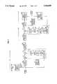
- FIG. 1is a block diagram of an embodiment of a satellite communications system according to the present invention including a hub station modulator 10, a communication link 120, and a remote terminal demodulator 130;
- FIG. 2shows a graphical representation of a single channel modulated spectrum according to a conventional system
- FIG. 3shows a graphical representation of an exemplary multichannel frequency diversity spectrum according to the present invention prior to compression where the number of channels equals 4;
- FIG. 4shows the line spectrum for sinusoidal tones which may be used to produce the frequency diversity spectrum of FIG. 3;
- FIG. 5shows a minimum spaced multichannel frequency diversity spectrum according to an exemplary embodiment of the present invention
- FIG. 6shows a phase-aligned multichannel frequency diversity spectrum according to the exemplary embodiment of the present invention depicted in FIG. 5;
- FIG. 7arepresents a first sine wave which is used to generate an analog waveform signal according to an exemplary embodiment of the present invention
- FIG. 7brepresents a second sine wave which is used to generate an analog waveform signal according to an exemplary embodiment of the present invention
- FIG. 7crepresents the sum of the first and second sine waves of FIGS. 7a and 7b according to an exemplary embodiment of the present invention
- FIG. 8shows an exemplary Costas loop demodulator according to the FIG. 1 embodiment of the present invention
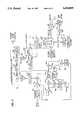
- FIG. 9shows another exemplary embodiment of a satellite communications system according to the present invention.
- FIG. 10is a further representation of the embodiment of FIG. 9;
- FIG. 11is a further representation of the embodiment of FIGS. 9 and 10.
- FIG. 12is a more detailed representation of the despreading waveform generator shown in FIG. 11.
- a hub stationmodulates information and wirelessly transmits the information to a satellite which in turn wirelessly transmits the information for reception and demodulation by the remote station.
- the hub stationprovides digital communication for a variety of services to a series of remote stations continuously.
- the data stream transmitted by the hub stationcontain messages addressed to individual remote stations. Each remote station processes only those messages with its own address. Additionally, each remote station can be interfaced with several data terminals, with individual messages for a respective data terminal from the hub station being separated by the remote station and then passed on to the data terminal.
- FIG. 1shows an exemplary satellite communications system for performing hub station to remote station communication.
- the hub station modulator 10receives information data and a data clock, for example at a rate such as 64 kbits/second. Bit errors due to transmission noise can occur, and may be greatly reduced by employing forward error correction encoding prior to transmission to the remote station.
- the information datamay optionally be encoded with error detection and/or correction information forming the symbol data by a forward error correction edcoder 20 using any one of a variety of methods known in the art. For example, prior to transmission, data can be specially coded to add redundancy.
- Exemplary coding techniquesinclude using parity bits or more elaborate forms such as a Hamming code which performs one level of error correction, by correcting a one bit error, and identifying a two bit error. Also, more complex forward error correction such as Huffman, Reed-Soloman, Viterbi, and sequential may be used, or a combination of some or all of the above.
- the symbol data and symbol clockare input to a pulse filter 30.
- the pulse filter 30can be replaced by any data modulator or encoder capable of producing the desired modulation data signal.
- the pulse filter 30receives a rectangular data input pulse signal and filters the signal into an appropriate spectrum.
- the resulting signalis mixed with a carrier frequency by a mixer 40, typically a multiplier, modulating the data by the carrier frequency to form a modulated data signal.
- a spreading waveform generator 50also receives the symbol clock input to the pulse filter 30.
- the spreading waveform generator 50may include a plurality of voltage controlled oscillators controlled by a voltage mathematically corresponding to the symbol clock (or data rate).
- the spreading waveform generator 50may include a counter 60, a read only memory (ROM) 70, a digital to analog converter 80, an amplifier 90, and an active filter 100.
- the counter 60receives the symbol clock and converts the symbol clock into a binary count for addressing the ROM 70, which preferably is programmable (PROM). Words stored in the ROM 70 represent stored digital waveforms.
- the counter 60addresses a plurality of, for example 32 states/waveform, stored digital waveforms (i.e., frequency control words) according to the binary count.
- the stored digital waveformswill be more particularly described, by way of example, in connection with the forthcoming discussion of FIGS. 7a, 7b, and 7c.
- a composite digital waveformincluding samples of the addressed digital waveforms, is sent to the digital to analog (D/A) converter 80 where the samples of the digital waveform are converted into an analog waveform signal output.
- An amplifier 90amplifies the analog waveform signal and passes the signal to an active filter which removes unwanted noise.
- the tones of FIG. 4may be generated utilizing conventional voltage controlled oscillators according to the number of carrier tones to be generated.
- such an embodimentwill not be as advantageous as the above described waveform generator because of the difficulty of assuring precise control of the phase.
- the modulated data signal output of the mixer 40is mixed with the analog waveform signal by a mixer 110, for example a multiplier, thereby spreading the modulated data signal over M channels (M ⁇ 2) in the analog waveform signal generated by the spreading waveform generator 50. Consequently, each channel contains the same modulated information.
- the analog waveform signalhas a particular phase relationship to the symbol rate (i.e., the symbol clock may be displaced from 0° to 90° from the symbol transition) so, when mixed with the modulated data signal, a phase-aligned multichannel frequency diversity spectrum results.
- the spread modulated data signalis then forwarded to a communication link 120.
- the communication link 120symbolically represents a number of items or products typically supplied in the art which will be described further herein.
- FIG. 2represents a single channel modulated spectrum currently being used in VSAT systems.
- a graphical representation of the radiated power level in dB versus a frequency to symbol rate ratiois shown generically for a data signal of a given bandwidth covering between a frequency to symbol rate ratio of -1 and +1.
- the communication link 120may include means for upconverting the spread modulated data signal to higher bands of frequencies (i.e., C-band or Ku-band (e.g., 14 to 14.5 GHz)) for satellite communication; a hub station satellite dish with a large diameter of 6-7 meters for transmitting the upconverted spread modulated data signal; a satellite for receiving the upconverted spread modulated data signal from the hub station, converting the received spread modulated data signal to another frequency within the bandwidth (e.g., for Ku-band, typically 11.7 to 12.2 GHz), and transmitting the spread modulated data signal to a 0.95 meter or less diameter satellite dish at the remote station; and means for downconverting the spread modulated data signal from the satellite to IF (e.g., 950-1700 MHz) for demodulation at the remote station by a demodulator 130.
- IFe.g., 950-1700 MHz
- a bandpass filter 140filters the received IF spread modulated data signal which downconverts the spread modulated data signal to a frequency of 44 MHz for example. Thereafter, the spread modulated data signal passes to a mixer 150 and through a Costas loop 160 to a symbol timing recovery circuit 170.
- the symbol timing recovery circuit 170detects the phase and phase locks to the symbol rate.
- the symbol clock (rate)is twice the bit rate and can be recovered from the bit rate.
- the symbol timing recovery circuit 170supplies the recovered symbol clock to the despreading waveform generator 180.
- the despreading waveform generator 180is similar to the spreading waveform generator 50 and includes a counter 190, a read only memory (ROM) 200, an intermediate buffer 210, a digital to analog converter 220, an amplifier 230, and an active filter 240.
- the counter 190receives the symbol clock and converts the symbol clock into a binary count for addressing the ROM 200, which preferably is programmable (PROM). Words stored in the ROM 200 represent stored states of the digital waveforms.
- the counter 190addresses the same stored words addressed by the counter 60 of the spreading waveform generator 50 according to the binary count. Thereafter, a composite digital waveform is sent to the intermediate buffer 210 which latches the information to the digital to analog (D/A) converter 220.
- D/Adigital to analog
- the D/A converter 220converts the composite digital waveform into an analog waveform signal.
- An amplifier 230amplifies the analog waveform signal and passes the signal to an active filter 240 which removes unwanted noise from the analog waveform signal.
- the analog waveform signalcontains the same number of channels as the analog waveform signal over which the symbol data was spread in the modulator 10.
- a plurality of voltage controlled oscillatorsmay be separately utilized to generate the despreading waveforms, the number of voltage controlled oscillators being dependent on M, the number of frequency diverse channels. Proper despreading is dependent on strict phase alignment of all VCO's relative to the symbol timing.
- the ROM 200preferably a PROM, is programmed to generate the number of carriers required for demodulation. When four carrier waveforms are generated, two frequencies are used, at one and three times the symbol clock. When combined with two sinusoidal tones and a phase of approximately 45°, the resulting signals are represented by sin(2 ⁇ *f 1 t+ ⁇ /4) and sin(2 ⁇ *3f 1 t+3 ⁇ /4) as shown in FIG. 7a and FIG. 7b respectively, where f 1 represents one-half the symbol rate.
- the symbol rate in a preferred embodimentis the encoded data rate which is twice the information data rate for a rate 1/2 coder.
- the two sine wave signalsare summed to form a carrier waveform having four channels with the symbol data being offset from the symbol clock by approximately 45° as shown in FIG. 7c, where symbol n represents the waveform corresponding to a first digital word, symbol n+1 represents the waveform corresponding to a second digital word, etc.
- the ROM 200outputs the digital words symbol n, symbol n+1, etc., where each represent a segment of the particular waveform at a particular point in time.
- the present invention arrangementanticipates a hybrid multichannel frequency diversity/spread spectrum system.
- the mixer 150mixes (e.g., multiplies) the analog waveform signal with the spread modulated data signal to despread the spread signal.
- the Costas loop 160alemodulates the resulting modulated data signal from the mixer 150 and recovers the symbol data which may be spread via well known spread spectrum techniques.
- Optional error correction and/or detectioncan be performed on the recovered symbol data with an error correction decoder 250 in conjunction with forward error correction performed at the hub station.
- demodulationmay be performed by a Costas loop which is known in the art.
- FIG. 8shows a block diagram of an exemplary Costas loop.
- the Costas loopgenerates a reference waveform at exactly the same frequency as the incoming modulated data signal, phase locked to the modulated data signal.
- the reference signalis mixed with the modulated data and filtered to remove higher-frequency components, the resulting sign at which results is an analog replica of the original data signal.
- Other carrier recovery methods known to those skilled in the artcan easily be adapted to the present invention.
- U.S. Pat. No. 4,344,178 to Waterswhich is herein incorporated by reference, discloses another Costas loop demodulator.
- a specific embodiment of the present inventioninvolves using binary phase shift keying (BPSK) modulation and demodulation, although other types of phase modulation may be employed such as QPSK (quadrature phase shift keying), MSK (minimum shift keying), FSK (frequency shift keying, M-ary PSK (M-ary phase shift keying), etc.
- BPSKbinary phase shift keying
- QPSKquadrature phase shift keying
- MSKminimum shift keying
- FSKfrequency shift keying
- M-ary PSKM-ary phase shift keying
- FIG. 9shows a block diagram of an exemplary system using BPSK.
- symbol datais input to an ASIC (e.g., a Xilinx XC3042) including a shift register 300 and a symbol phase counter 305.
- the symbol phase counter 305provides a symbol clock to the shift register 300 which receives the symbol data and generates multiple phases of the symbol clock.
- the shift register 300outputs 8 bits of symbol to a PROM 310.
- Four symbol clock phases from the symbol phase counter in conjunction with a bit clock from the symbol phase counter 305address the PROM 310 which contains stored words representing the composite digital waveforms. The purpose of the PROM is two-fold:
- the PROMalso imparts the spreading waveform. Since 16 phases per symbol are input to the PROM via 4 address lines, an additional signal (e.g. the bit clock for a rate one-half encoding scheme) fully defines the 32-states needed to generate the spreading waveform. For the four tone example the PROM multiplies the FIR output by:
- a PROM with 8-bits of shift register input and 4 bits of symbol phase timingproduces the pulse-shape filtered spectra mixed with the multiple tone spreading waveform.
- Any PROM of size 8K ⁇ 8can be produced by a person skilled in the art. According to a preferred embodiment, and Advanced Micro Devices AM 27C512 can be employed.
- the D/A converter 320can be any converter capable of converting eight digital word inputs to the waveform output of 7a, 7b, and 7c, for example a Motorola MC 10322.
- the analog waveform signalis then amplified by an amplifier stage 330 and filtered by an active filter stage 340 utilized for anti-aliasing as shown in FIG. 9.
- Optional forward error correctioncan be performed on the symbol data prior to mixing the data with the analog waveform signal.
- a communication linkincludes an upconverter 360, a hub satellite dish 370, a satellite 380, wireless links 375 and 385, a remote satellite dish 390, a low noise downconverter 400, and an upconverter 410.
- the communication linkperforms the appropriate upconverting and downconverting for hub station to satellite and satellite to remote station communication.
- the upconverter 360upconverts the spread modulated data signal to Ku-band with a frequency of 14-14.5 GHz.
- a hub station satellite dish 370 with a diameter of approximately 6-7 meterstransmits the upconverted spread modulated data signal to the satellite 380.
- the satellite 380receives the upconverted spread modulated data signal, converts the spread modulated data signal to another Ku-band frequency from 11.7-12.2 GHz, and transmits the spread modulated data signal to a remote station satellite dish 390 of less than one meter, for example.
- the spread modulated data signalis downconverted to an IF of 950-1700 MHz by a downconverter 400.
- An interfacility linkconnects the downconverter 400 with a quadplexer 420.
- the IFLis a cable (e.g., a 50 Ohm coax with low-loss foam insulation, in the general class of RG-58U or RG-8U depending upon the required length) for connecting outdoor radio equipment including the remote station satellite dish 390, the low noise downconverter 400, and the upconverter 430 with indoor radio equipment including the receiving portion 422 of the quadplexer 420, the transmitting portion 424 of the quadplexer 420, and further modulation equipment 440 and demodulation equipment (shown in FIG. 11 ) for transmission and reception respectively.
- the remote stationin addition to receiving transmissions from the hub station via the communication link, can also through the modulation equipment 440 and the transmitting portion 424 of the quadplexer 420, transmit data messages via the satellite to the hub station.
- the quadplexer 420uses frequency bandpass filters (not shown) to separate transmit, receive, reference, and control signals and DC power.
- the receiving portionsends the spread modulated data signal downconverted to an IF frequency range of 950-1700 MHz to another downconverter 450 for further downconversion to a final IF of 44 MHz for demodulation. IF frequencies other than 44 MHz may be used as well.
- the downconverter 450typically includes a series of filters and phase locked loops to downconvert the spread modulated data signal to 44 MHz.
- An amplifier 460performs automatic gain control on the 44 MHz spread modulated data signal.
- the spread modulated data signalis mixed with an analog waveform generated by a despreading waveform generator 480 at a mixer 470.
- the despreading waveform generator 480includes a PROM 500 which receives the recovered symbol clocks, a buffer 510, a D/A converter 520, an amplifier stage 530, and an active filter stage 540.
- the PROM 500may be an Advanced Micro Devices 27C256.
- FIG. 12A more detailed representation of the despreading waveform generator 480 is shown in FIG. 12.
- the recovered symbol clocks from the symbol recovery circuitaddress the PROM 500.
- the PROM 500contains stored words representing states of the digital waveform.
- An intermediate storage buffer 510receives samples of a composite digital waveform based on the stored waveforms addressed in the PROM 500.
- samples of the composite digital waveformare latched to the D/A converter 520 which converts the samples of the composite digital waveform into an analog waveform signal.
- the amplifier stage 530 and the active filter stage 540respectively amplify and filter the despreading analog waveform to the appropriate frequency level which is the same as the frequency level of the analog waveform signal generated by the spreading analog waveform signal.
- the despreading analog waveform signalis mixed with the spread modulated data signal received from the automatic gain control amplifier 460 by the mixer 470 to despread the spread modulated data signal.
- the resulting modulated data signalappears as one signal as shown for example in the phased aligned multichannel frequency diversity spectrum represented in FIG. 6.
- the modulated data signalis amplified by an amplifier 550 and fed to a Costas loop for further demodulation. Specifically, a pair of mixers 560a and 560b divides the amplified signal into I and Q channel signals.
- An 88 MHz crystalprovides a VCO 570 with an oscillating frequency of 88 MHz which passes to a frequency divider 580 to lock the modulated data signal to 44 MHz.
- the frequency divider 580divides the 88 MHz frequency signal by two and provides the respective mixers 560a and 560b with 44 MHz frequency signals separated by a phase of 90°.
- a frequency signal of exactly the same frequency as the incoming modulated data signal, phase locked to the modulated data signalis mixed with the modulated data signal at the mixers 560a and 560b.
- the I and Q channel signals from mixers 560a and 560bare respectively filtered by matched filters 590a and 590b to remove high frequency components and produce the original components of the original modulation.
- the output of the filters 590a and 590bis squared by mixers 600a and 600b respectively.
- the squared signalsare combined by a summer 610 and subsequently filtered by a loop filter 620 and input to the automatic gain control circuit 460 via a resistor.
- a soft decoder 630receives the filtered I channel signal from the matched filter 590a and roughly estimates the I channel signal.
- the output of the soft decoder 630includes a magnitude, I mag , and sign, I sign , estimate of the I channel signal.
- a hard decoder 640receives I mag , I sign , a reference frequency signal of 32 MHz provided by a VCO 650 controlled by a 32 MHz crystal, and a receiver symbol clock from a divider 660 (operation to be explained later).
- the hard decoder 640performs digital "hard decisions" on the I mag and I sign representation of the original modulated data signal to recover a true digital waveform. To reduce noise effects, the recovered receiver symbol clock reclocks the hard decision demodulated data near the center of each bit, where the bit amplitude prior to each hard decisions is greatest and noise effects are minimized.
- a timing recovery circuitreceives the I sign signal and through various circuitry recovers the receiver symbol clocks which are forwarded to the despreading waveform generator 480 utilized in generation of the despreading waveform.
- a phase detector 670receives the I sign signal from the soft decoder 630 and the receiver symbol clock from the divider 660 and detects the clock phase of the original modulated data signal.
- a digital loop filter 680filters the clock phase and inputs the phase to the divider 660.
- the divider 660also receives a frequency signal of 32 MHz or 28.672 MHz from a phase-locked loop 690 which runs locked to a 10 MHz reference frequency.
- a 32/28 Mhz jumperprovides an input frequency to the phase-locked loop.
- a VCO 700also receives the phase-locked loop frequency signal and oscillates at a selected frequency according to the phase-locked loop 690.
- the VCO frequency signalis filtered by a loop filter 710 and sent to the phase-locked loop 690.
- the divider 720determines the transmitter symbol clocks for modulator encoding which is sent to the modulation equipment for the transmission of information by the remote station to the hub station.
- the divider 720also receives a frequency signal from the phase-locked loop 690 and the divisor N from serial control (as described above).
Landscapes
- Engineering & Computer Science (AREA)
- Computer Networks & Wireless Communication (AREA)
- Signal Processing (AREA)
- Physics & Mathematics (AREA)
- Astronomy & Astrophysics (AREA)
- Aviation & Aerospace Engineering (AREA)
- General Physics & Mathematics (AREA)
- Digital Transmission Methods That Use Modulated Carrier Waves (AREA)
Abstract
Description
Cos(2π*n/32+φ)+Cos(2π*3n/32+3φ) for n=0 . . . 32
Claims (77)
Priority Applications (1)
| Application Number | Priority Date | Filing Date | Title |
|---|---|---|---|
| US08/181,318US5454009A (en) | 1994-01-13 | 1994-01-13 | Method and apparatus for providing energy dispersal using frequency diversity in a satellite communications system |
Applications Claiming Priority (1)
| Application Number | Priority Date | Filing Date | Title |
|---|---|---|---|
| US08/181,318US5454009A (en) | 1994-01-13 | 1994-01-13 | Method and apparatus for providing energy dispersal using frequency diversity in a satellite communications system |
Publications (1)
| Publication Number | Publication Date |
|---|---|
| US5454009Atrue US5454009A (en) | 1995-09-26 |
Family
ID=22663782
Family Applications (1)
| Application Number | Title | Priority Date | Filing Date |
|---|---|---|---|
| US08/181,318Expired - LifetimeUS5454009A (en) | 1994-01-13 | 1994-01-13 | Method and apparatus for providing energy dispersal using frequency diversity in a satellite communications system |
Country Status (1)
| Country | Link |
|---|---|
| US (1) | US5454009A (en) |
Cited By (66)
| Publication number | Priority date | Publication date | Assignee | Title |
|---|---|---|---|---|
| WO1996020538A3 (en)* | 1994-11-15 | 1996-09-06 | Stanford Telecomm Inc | Reliable, power-efficient, and cost-effective satellite communication system |
| US5774788A (en)* | 1995-03-17 | 1998-06-30 | Hughes Electronics | Remote ground terminal having an outdoor unit with a frequency-multiplier |
| US5790601A (en)* | 1995-02-21 | 1998-08-04 | Hughes Electronics | Low cost very small aperture satellite terminal |
| US5812604A (en)* | 1996-07-16 | 1998-09-22 | Scientific-Atlanta, Inc. | Constant envelope continuous phase frequency shift key modulation apparatus and method at radio frequencies |
| US5828709A (en)* | 1994-12-30 | 1998-10-27 | Hyundi Electronics Industries Co., Ltd. | Apparatus and method for improving stability of transmitting frequency by using costas loop section in communication system of half duplex transmitting method |
| US6005898A (en)* | 1997-03-12 | 1999-12-21 | Interdigital Technology Corporation | Multichannel viterbi decoder |
| US6049706A (en) | 1998-10-21 | 2000-04-11 | Parkervision, Inc. | Integrated frequency translation and selectivity |
| US6061555A (en) | 1998-10-21 | 2000-05-09 | Parkervision, Inc. | Method and system for ensuring reception of a communications signal |
| US6061551A (en) | 1998-10-21 | 2000-05-09 | Parkervision, Inc. | Method and system for down-converting electromagnetic signals |
| US6091940A (en) | 1998-10-21 | 2000-07-18 | Parkervision, Inc. | Method and system for frequency up-conversion |
| WO2001013562A3 (en)* | 1999-08-13 | 2002-01-10 | Comsat Corp | A high speed burst-mode digital demodulator architecture |
| WO2002013432A1 (en)* | 2000-08-03 | 2002-02-14 | Lockheed Martin Corporation | Phase shift keyed signaling with forward error correction and raman amplification in optical wdm links |
| US6370371B1 (en) | 1998-10-21 | 2002-04-09 | Parkervision, Inc. | Applications of universal frequency translation |
| US6404828B2 (en) | 1997-03-12 | 2002-06-11 | Interdigital Technology Corporation | Multichannel decoder |
| US20030027519A1 (en)* | 2001-08-01 | 2003-02-06 | Philippe Bouvet | Process and device for installing broadcast programmes |
| US6542722B1 (en) | 1998-10-21 | 2003-04-01 | Parkervision, Inc. | Method and system for frequency up-conversion with variety of transmitter configurations |
| US6560301B1 (en) | 1998-10-21 | 2003-05-06 | Parkervision, Inc. | Integrated frequency translation and selectivity with a variety of filter embodiments |
| US6694128B1 (en) | 1998-08-18 | 2004-02-17 | Parkervision, Inc. | Frequency synthesizer using universal frequency translation technology |
| US6704558B1 (en) | 1999-01-22 | 2004-03-09 | Parkervision, Inc. | Image-reject down-converter and embodiments thereof, such as the family radio service |
| US6704549B1 (en) | 1999-03-03 | 2004-03-09 | Parkvision, Inc. | Multi-mode, multi-band communication system |
| EP1046246A4 (en)* | 1998-02-04 | 2004-06-09 | Robert F Friedman | Method and apparatus for combining transponders on multiple satellites into virtual channels |
| DE10300329A1 (en)* | 2002-12-16 | 2004-07-22 | Daimlerchrysler Ag | Direct sequence spread spectrum collision detection multiple access transmission involves associating pseudorandom sequence code states to signal depending on counter, pseudorandom sequence modulation |
| US6813485B2 (en) | 1998-10-21 | 2004-11-02 | Parkervision, Inc. | Method and system for down-converting and up-converting an electromagnetic signal, and transforms for same |
| US6873836B1 (en) | 1999-03-03 | 2005-03-29 | Parkervision, Inc. | Universal platform module and methods and apparatuses relating thereto enabled by universal frequency translation technology |
| US6879817B1 (en) | 1999-04-16 | 2005-04-12 | Parkervision, Inc. | DC offset, re-radiation, and I/Q solutions using universal frequency translation technology |
| US20050111578A1 (en)* | 2002-02-22 | 2005-05-26 | Thales | Frequency modulator for digital transmissions |
| US20050130701A1 (en)* | 1997-06-19 | 2005-06-16 | Idt Corporation | Metropolitan wide area network |
| US20050143004A1 (en)* | 2003-11-26 | 2005-06-30 | Dibiaso Eric A. | Method to optimize hierarchical modulation for a diversity system |
| US20050179570A1 (en)* | 2003-12-19 | 2005-08-18 | Tetsuya Yagi | Energy dispersal circuit and receiver |
| US6944139B1 (en) | 1998-03-27 | 2005-09-13 | Worldspace Management Corporation | Digital broadcast system using satellite direct broadcast and terrestrial repeater |
| US6956814B1 (en) | 2000-02-29 | 2005-10-18 | Worldspace Corporation | Method and apparatus for mobile platform reception and synchronization in direct digital satellite broadcast system |
| US6963734B2 (en) | 1999-12-22 | 2005-11-08 | Parkervision, Inc. | Differential frequency down-conversion using techniques of universal frequency translation technology |
| US6975848B2 (en) | 2002-06-04 | 2005-12-13 | Parkervision, Inc. | Method and apparatus for DC offset removal in a radio frequency communication channel |
| US7006805B1 (en) | 1999-01-22 | 2006-02-28 | Parker Vision, Inc. | Aliasing communication system with multi-mode and multi-band functionality and embodiments thereof, such as the family radio service |
| US7010559B2 (en) | 2000-11-14 | 2006-03-07 | Parkervision, Inc. | Method and apparatus for a parallel correlator and applications thereof |
| US7010286B2 (en) | 2000-04-14 | 2006-03-07 | Parkervision, Inc. | Apparatus, system, and method for down-converting and up-converting electromagnetic signals |
| US7027786B1 (en) | 1998-10-21 | 2006-04-11 | Parkervision, Inc. | Carrier and clock recovery using universal frequency translation |
| US20060087972A1 (en)* | 2001-11-21 | 2006-04-27 | Ahmad Jalali | Rate selection for an OFDM system |
| US7039372B1 (en) | 1998-10-21 | 2006-05-02 | Parkervision, Inc. | Method and system for frequency up-conversion with modulation embodiments |
| US7054296B1 (en) | 1999-08-04 | 2006-05-30 | Parkervision, Inc. | Wireless local area network (WLAN) technology and applications including techniques of universal frequency translation |
| US7072427B2 (en) | 2001-11-09 | 2006-07-04 | Parkervision, Inc. | Method and apparatus for reducing DC offsets in a communication system |
| US7072390B1 (en) | 1999-08-04 | 2006-07-04 | Parkervision, Inc. | Wireless local area network (WLAN) using universal frequency translation technology including multi-phase embodiments |
| US7082171B1 (en) | 1999-11-24 | 2006-07-25 | Parkervision, Inc. | Phase shifting applications of universal frequency translation |
| US7085335B2 (en) | 2001-11-09 | 2006-08-01 | Parkervision, Inc. | Method and apparatus for reducing DC offsets in a communication system |
| US20060182185A1 (en)* | 2004-12-22 | 2006-08-17 | Tomoya Horiguchi | Radio communication system and radio transmitter |
| US7110435B1 (en) | 1999-03-15 | 2006-09-19 | Parkervision, Inc. | Spread spectrum applications of universal frequency translation |
| US7110444B1 (en) | 1999-08-04 | 2006-09-19 | Parkervision, Inc. | Wireless local area network (WLAN) using universal frequency translation technology including multi-phase embodiments and circuit implementations |
| US20060262832A1 (en)* | 1997-03-12 | 2006-11-23 | Interdigital Technology Corporation | Convolutionally encoding and decoding multiple data streams |
| US7236754B2 (en) | 1999-08-23 | 2007-06-26 | Parkervision, Inc. | Method and system for frequency up-conversion |
| US7292835B2 (en) | 2000-01-28 | 2007-11-06 | Parkervision, Inc. | Wireless and wired cable modem applications of universal frequency translation technology |
| US7295826B1 (en) | 1998-10-21 | 2007-11-13 | Parkervision, Inc. | Integrated frequency translation and selectivity with gain control functionality, and applications thereof |
| US7321640B2 (en) | 2002-06-07 | 2008-01-22 | Parkervision, Inc. | Active polyphase inverter filter for quadrature signal generation |
| US7379883B2 (en) | 2002-07-18 | 2008-05-27 | Parkervision, Inc. | Networking methods and systems |
| US7454453B2 (en) | 2000-11-14 | 2008-11-18 | Parkervision, Inc. | Methods, systems, and computer program products for parallel correlation and applications thereof |
| US7460584B2 (en) | 2002-07-18 | 2008-12-02 | Parkervision, Inc. | Networking methods and systems |
| US7515896B1 (en) | 1998-10-21 | 2009-04-07 | Parkervision, Inc. | Method and system for down-converting an electromagnetic signal, and transforms for same, and aperture relationships |
| US20090156117A1 (en)* | 2007-12-18 | 2009-06-18 | Qualcomm Incorporated | High reliability satellite network delivery |
| US7554508B2 (en) | 2000-06-09 | 2009-06-30 | Parker Vision, Inc. | Phased array antenna applications on universal frequency translation |
| US7693230B2 (en) | 1999-04-16 | 2010-04-06 | Parkervision, Inc. | Apparatus and method of differential IQ frequency up-conversion |
| US7715461B2 (en) | 1996-05-28 | 2010-05-11 | Qualcomm, Incorporated | High data rate CDMA wireless communication system using variable sized channel codes |
| US7724845B2 (en) | 1999-04-16 | 2010-05-25 | Parkervision, Inc. | Method and system for down-converting and electromagnetic signal, and transforms for same |
| US7773688B2 (en) | 1999-04-16 | 2010-08-10 | Parkervision, Inc. | Method, system, and apparatus for balanced frequency up-conversion, including circuitry to directly couple the outputs of multiple transistors |
| US20110028086A1 (en)* | 2009-08-14 | 2011-02-03 | Abel Avellan | System and method for enabling ultra small aperture communication antenna using spectral replication and coherent frequency and phase combining |
| US20110028088A1 (en)* | 2009-08-14 | 2011-02-03 | EMC SatCom Technologies Inc. | System and method for enabling ultra small aperture communication antenna using spectral replication and coherent frequency and phase combining |
| US8295406B1 (en) | 1999-08-04 | 2012-10-23 | Parkervision, Inc. | Universal platform module for a plurality of communication protocols |
| CN110031873A (en)* | 2019-04-17 | 2019-07-19 | 桂林电子科技大学 | GNSS multipath signal analogy method and GNSS multipath signal simulator |
Citations (29)
| Publication number | Priority date | Publication date | Assignee | Title |
|---|---|---|---|---|
| US3816657A (en)* | 1972-10-12 | 1974-06-11 | Nasa | Differential phase-shift-keyed communication system |
| US4344178A (en)* | 1980-09-26 | 1982-08-10 | Harris Corporation | Costas loop QPSK demodulator |
| US4375099A (en)* | 1980-04-08 | 1983-02-22 | Harris Corporation | Link performance indicator with alternate data sampling and error indication generation |
| US4389722A (en)* | 1979-09-13 | 1983-06-21 | Licentia Patent-Verwaltungs-Gmbh | Method for the simultaneous transmission of a plurality of data stream over one transmission channel |
| US4423390A (en)* | 1981-01-09 | 1983-12-27 | Harris Corporation | Side lock avoidance network for PSK demodulator |
| US4455651A (en)* | 1980-10-20 | 1984-06-19 | Equatorial Communications Company | Satellite communications system and apparatus |
| US4587661A (en)* | 1983-03-04 | 1986-05-06 | Rca Corporation | Apparatus for synchronizing spread spectrum transmissions from small earth stations used for satellite transmission |
| US4653053A (en)* | 1984-05-11 | 1987-03-24 | Harris Corporation | Performance monitoring of antijam satellite communication network |
| US4707839A (en)* | 1983-09-26 | 1987-11-17 | Harris Corporation | Spread spectrum correlator for recovering CCSK data from a PN spread MSK waveform |
| US4748622A (en)* | 1985-08-28 | 1988-05-31 | Kokusai Denshin Denwa Co., Ltd. | Satellite communication system |
| US4765753A (en)* | 1986-03-08 | 1988-08-23 | U.S. Philips Corporation | Method and apparatus for handing-over a radio connection from one radio cell to another radio cell of a digital radio transmission system |
| USRE32905E (en)* | 1980-10-20 | 1989-04-11 | Equatorial Communications Company | Satellite communications system and apparatus |
| US4821120A (en)* | 1985-06-13 | 1989-04-11 | Devon County Council | Television sub-carrier transmission |
| US4901368A (en)* | 1987-10-19 | 1990-02-13 | American Telephone And Telegraph Company | Frequency translation correction scheme for satellite communication system |
| US4907181A (en)* | 1987-06-11 | 1990-03-06 | Robert Bosch Gmbh | Test and monitoring system for a digital video tape recorder/reproducer |
| US4932070A (en)* | 1988-08-22 | 1990-06-05 | Scientific Atlanta | Mechanism for deriving accurate frequency reference for satellite communications burst demodulator |
| US4943976A (en)* | 1988-09-16 | 1990-07-24 | Victor Company Of Japan, Ltd. | Spread spectrum communication system |
| US4953178A (en)* | 1988-09-16 | 1990-08-28 | Victor Company Of Japan, Ltd. | Spread spectrum communication system |
| US4977578A (en)* | 1988-02-19 | 1990-12-11 | Victor Company Of Japan, Ltd. | Spread spectrum communication system |
| US5020075A (en)* | 1988-09-06 | 1991-05-28 | Mitsubishi Denki Kabushiki Kaisha | Direct sequence spread spectrum modulation apparatus |
| US5144640A (en)* | 1990-01-31 | 1992-09-01 | Futaba Denshi Kogyo K.K. | Correlation device for spectrum spread communication |
| US5151919A (en)* | 1990-12-17 | 1992-09-29 | Ericsson-Ge Mobile Communications Holding Inc. | Cdma subtractive demodulation |
| US5157686A (en)* | 1990-05-24 | 1992-10-20 | Cylink Corporation | Method and apparatus for the modulation of spread spectrum radio signals |
| US5170411A (en)* | 1990-09-21 | 1992-12-08 | Victor Company Of Japan, Ltd. | Modulation and demodulation system for spread spectrum transmission |
| US5177766A (en)* | 1991-06-03 | 1993-01-05 | Spectralink Corporation | Digital clock timing generation in a spread-spectrum digital communication system |
| US5177765A (en)* | 1991-06-03 | 1993-01-05 | Spectralink Corporation | Direct-sequence spread-spectrum digital signal acquisition and tracking system and method therefor |
| US5189683A (en)* | 1989-03-23 | 1993-02-23 | Echelon Corporation | Transceiver providing selectable frequencies and spreading sequences |
| US5204876A (en)* | 1991-03-13 | 1993-04-20 | Motorola, Inc. | Method and apparatus for providing high data rate traffic channels in a spread spectrum communication system |
| US5210770A (en)* | 1991-09-27 | 1993-05-11 | Lockheed Missiles & Space Company, Inc. | Multiple-signal spread-spectrum transceiver |
- 1994
- 1994-01-13USUS08/181,318patent/US5454009A/ennot_activeExpired - Lifetime
Patent Citations (30)
| Publication number | Priority date | Publication date | Assignee | Title |
|---|---|---|---|---|
| US3816657A (en)* | 1972-10-12 | 1974-06-11 | Nasa | Differential phase-shift-keyed communication system |
| US4389722A (en)* | 1979-09-13 | 1983-06-21 | Licentia Patent-Verwaltungs-Gmbh | Method for the simultaneous transmission of a plurality of data stream over one transmission channel |
| US4375099A (en)* | 1980-04-08 | 1983-02-22 | Harris Corporation | Link performance indicator with alternate data sampling and error indication generation |
| US4344178A (en)* | 1980-09-26 | 1982-08-10 | Harris Corporation | Costas loop QPSK demodulator |
| USRE32905E (en)* | 1980-10-20 | 1989-04-11 | Equatorial Communications Company | Satellite communications system and apparatus |
| US4455651A (en)* | 1980-10-20 | 1984-06-19 | Equatorial Communications Company | Satellite communications system and apparatus |
| USRE32905F1 (en)* | 1980-10-20 | 1992-11-10 | Satellite communications system and apparatus | |
| US4423390A (en)* | 1981-01-09 | 1983-12-27 | Harris Corporation | Side lock avoidance network for PSK demodulator |
| US4587661A (en)* | 1983-03-04 | 1986-05-06 | Rca Corporation | Apparatus for synchronizing spread spectrum transmissions from small earth stations used for satellite transmission |
| US4707839A (en)* | 1983-09-26 | 1987-11-17 | Harris Corporation | Spread spectrum correlator for recovering CCSK data from a PN spread MSK waveform |
| US4653053A (en)* | 1984-05-11 | 1987-03-24 | Harris Corporation | Performance monitoring of antijam satellite communication network |
| US4821120A (en)* | 1985-06-13 | 1989-04-11 | Devon County Council | Television sub-carrier transmission |
| US4748622A (en)* | 1985-08-28 | 1988-05-31 | Kokusai Denshin Denwa Co., Ltd. | Satellite communication system |
| US4765753A (en)* | 1986-03-08 | 1988-08-23 | U.S. Philips Corporation | Method and apparatus for handing-over a radio connection from one radio cell to another radio cell of a digital radio transmission system |
| US4907181A (en)* | 1987-06-11 | 1990-03-06 | Robert Bosch Gmbh | Test and monitoring system for a digital video tape recorder/reproducer |
| US4901368A (en)* | 1987-10-19 | 1990-02-13 | American Telephone And Telegraph Company | Frequency translation correction scheme for satellite communication system |
| US4977578A (en)* | 1988-02-19 | 1990-12-11 | Victor Company Of Japan, Ltd. | Spread spectrum communication system |
| US4932070A (en)* | 1988-08-22 | 1990-06-05 | Scientific Atlanta | Mechanism for deriving accurate frequency reference for satellite communications burst demodulator |
| US5020075A (en)* | 1988-09-06 | 1991-05-28 | Mitsubishi Denki Kabushiki Kaisha | Direct sequence spread spectrum modulation apparatus |
| US4943976A (en)* | 1988-09-16 | 1990-07-24 | Victor Company Of Japan, Ltd. | Spread spectrum communication system |
| US4953178A (en)* | 1988-09-16 | 1990-08-28 | Victor Company Of Japan, Ltd. | Spread spectrum communication system |
| US5189683A (en)* | 1989-03-23 | 1993-02-23 | Echelon Corporation | Transceiver providing selectable frequencies and spreading sequences |
| US5144640A (en)* | 1990-01-31 | 1992-09-01 | Futaba Denshi Kogyo K.K. | Correlation device for spectrum spread communication |
| US5157686A (en)* | 1990-05-24 | 1992-10-20 | Cylink Corporation | Method and apparatus for the modulation of spread spectrum radio signals |
| US5170411A (en)* | 1990-09-21 | 1992-12-08 | Victor Company Of Japan, Ltd. | Modulation and demodulation system for spread spectrum transmission |
| US5151919A (en)* | 1990-12-17 | 1992-09-29 | Ericsson-Ge Mobile Communications Holding Inc. | Cdma subtractive demodulation |
| US5204876A (en)* | 1991-03-13 | 1993-04-20 | Motorola, Inc. | Method and apparatus for providing high data rate traffic channels in a spread spectrum communication system |
| US5177766A (en)* | 1991-06-03 | 1993-01-05 | Spectralink Corporation | Digital clock timing generation in a spread-spectrum digital communication system |
| US5177765A (en)* | 1991-06-03 | 1993-01-05 | Spectralink Corporation | Direct-sequence spread-spectrum digital signal acquisition and tracking system and method therefor |
| US5210770A (en)* | 1991-09-27 | 1993-05-11 | Lockheed Missiles & Space Company, Inc. | Multiple-signal spread-spectrum transceiver |
Cited By (152)
| Publication number | Priority date | Publication date | Assignee | Title |
|---|---|---|---|---|
| US5638399A (en)* | 1994-11-15 | 1997-06-10 | Stanford Telecommunications, Inc. | Multi-beam satellite communication system with user terminal frequencies having transceivers using the same set of frequency hopping |
| WO1996020538A3 (en)* | 1994-11-15 | 1996-09-06 | Stanford Telecomm Inc | Reliable, power-efficient, and cost-effective satellite communication system |
| US5828709A (en)* | 1994-12-30 | 1998-10-27 | Hyundi Electronics Industries Co., Ltd. | Apparatus and method for improving stability of transmitting frequency by using costas loop section in communication system of half duplex transmitting method |
| US5790601A (en)* | 1995-02-21 | 1998-08-04 | Hughes Electronics | Low cost very small aperture satellite terminal |
| US5774788A (en)* | 1995-03-17 | 1998-06-30 | Hughes Electronics | Remote ground terminal having an outdoor unit with a frequency-multiplier |
| US7715461B2 (en) | 1996-05-28 | 2010-05-11 | Qualcomm, Incorporated | High data rate CDMA wireless communication system using variable sized channel codes |
| US8213485B2 (en) | 1996-05-28 | 2012-07-03 | Qualcomm Incorporated | High rate CDMA wireless communication system using variable sized channel codes |
| US8588277B2 (en) | 1996-05-28 | 2013-11-19 | Qualcomm Incorporated | High data rate CDMA wireless communication system using variable sized channel codes |
| US5812604A (en)* | 1996-07-16 | 1998-09-22 | Scientific-Atlanta, Inc. | Constant envelope continuous phase frequency shift key modulation apparatus and method at radio frequencies |
| US6005898A (en)* | 1997-03-12 | 1999-12-21 | Interdigital Technology Corporation | Multichannel viterbi decoder |
| US6577673B2 (en) | 1997-03-12 | 2003-06-10 | Interdigital Technology Corporation | Spread spectrum base station for simultaneously receiving and processing multiple channels of data |
| US6256339B1 (en) | 1997-03-12 | 2001-07-03 | Interdigital Technology Corporation | Multichannel viterbi decoder |
| US20040071233A1 (en)* | 1997-03-12 | 2004-04-15 | Interdigital Technology Corporation | Method for simultaneously receiving and processing multiple channels of data |
| US7088764B2 (en) | 1997-03-12 | 2006-08-08 | Interdigital Technology Corporation | Method for determining signal quality of simultaneously received multiple channels of data |
| US20060262832A1 (en)* | 1997-03-12 | 2006-11-23 | Interdigital Technology Corporation | Convolutionally encoding and decoding multiple data streams |
| US6577672B2 (en) | 1997-03-12 | 2003-06-10 | Interdigital Technology Corporation | Spread spectrum mobile station for simultaneously receiving and processing multiple channels of data |
| US20050163195A1 (en)* | 1997-03-12 | 2005-07-28 | Interdigital Technology Corporation | Method for determining signal quality of simultaneously received multiple channels of data |
| US6404828B2 (en) | 1997-03-12 | 2002-06-11 | Interdigital Technology Corporation | Multichannel decoder |
| US6865217B2 (en) | 1997-03-12 | 2005-03-08 | Interdigital Technology Corporation | Method for simultaneously receiving and processing multiple channels of data |
| US20050130701A1 (en)* | 1997-06-19 | 2005-06-16 | Idt Corporation | Metropolitan wide area network |
| US8223726B2 (en)* | 1997-06-19 | 2012-07-17 | Idt Capital, Inc. | Metropolitan wide area network |
| US20060126750A1 (en)* | 1998-02-04 | 2006-06-15 | Friedman Robert F | Method and apparatus for combining transponders on multiple satellites into virtual channels |
| EP1046246A4 (en)* | 1998-02-04 | 2004-06-09 | Robert F Friedman | Method and apparatus for combining transponders on multiple satellites into virtual channels |
| US7646834B2 (en) | 1998-02-04 | 2010-01-12 | Virlite Communicaton Limited Liability Company | Method and apparatus for combining transponders on multiple satellites into virtual channels |
| US6944139B1 (en) | 1998-03-27 | 2005-09-13 | Worldspace Management Corporation | Digital broadcast system using satellite direct broadcast and terrestrial repeater |
| US6694128B1 (en) | 1998-08-18 | 2004-02-17 | Parkervision, Inc. | Frequency synthesizer using universal frequency translation technology |
| US8233855B2 (en) | 1998-10-21 | 2012-07-31 | Parkervision, Inc. | Up-conversion based on gated information signal |
| US7016663B2 (en) | 1998-10-21 | 2006-03-21 | Parkervision, Inc. | Applications of universal frequency translation |
| US7295826B1 (en) | 1998-10-21 | 2007-11-13 | Parkervision, Inc. | Integrated frequency translation and selectivity with gain control functionality, and applications thereof |
| US7308242B2 (en) | 1998-10-21 | 2007-12-11 | Parkervision, Inc. | Method and system for down-converting and up-converting an electromagnetic signal, and transforms for same |
| US6647250B1 (en) | 1998-10-21 | 2003-11-11 | Parkervision, Inc. | Method and system for ensuring reception of a communications signal |
| US6580902B1 (en) | 1998-10-21 | 2003-06-17 | Parkervision, Inc. | Frequency translation using optimized switch structures |
| US6560301B1 (en) | 1998-10-21 | 2003-05-06 | Parkervision, Inc. | Integrated frequency translation and selectivity with a variety of filter embodiments |
| US6798351B1 (en) | 1998-10-21 | 2004-09-28 | Parkervision, Inc. | Automated meter reader applications of universal frequency translation |
| US6813485B2 (en) | 1998-10-21 | 2004-11-02 | Parkervision, Inc. | Method and system for down-converting and up-converting an electromagnetic signal, and transforms for same |
| US6836650B2 (en) | 1998-10-21 | 2004-12-28 | Parkervision, Inc. | Methods and systems for down-converting electromagnetic signals, and applications thereof |
| US6542722B1 (en) | 1998-10-21 | 2003-04-01 | Parkervision, Inc. | Method and system for frequency up-conversion with variety of transmitter configurations |
| US7321735B1 (en) | 1998-10-21 | 2008-01-22 | Parkervision, Inc. | Optical down-converter using universal frequency translation technology |
| US7245886B2 (en) | 1998-10-21 | 2007-07-17 | Parkervision, Inc. | Method and system for frequency up-conversion with modulation embodiments |
| US8190116B2 (en) | 1998-10-21 | 2012-05-29 | Parker Vision, Inc. | Methods and systems for down-converting a signal using a complementary transistor structure |
| US6421534B1 (en) | 1998-10-21 | 2002-07-16 | Parkervision, Inc. | Integrated frequency translation and selectivity |
| US8190108B2 (en) | 1998-10-21 | 2012-05-29 | Parkervision, Inc. | Method and system for frequency up-conversion |
| US6370371B1 (en) | 1998-10-21 | 2002-04-09 | Parkervision, Inc. | Applications of universal frequency translation |
| US8160534B2 (en) | 1998-10-21 | 2012-04-17 | Parkervision, Inc. | Applications of universal frequency translation |
| US6353735B1 (en) | 1998-10-21 | 2002-03-05 | Parkervision, Inc. | MDG method for output signal generation |
| US8019291B2 (en) | 1998-10-21 | 2011-09-13 | Parkervision, Inc. | Method and system for frequency down-conversion and frequency up-conversion |
| US7937059B2 (en) | 1998-10-21 | 2011-05-03 | Parkervision, Inc. | Converting an electromagnetic signal via sub-sampling |
| US7936022B2 (en) | 1998-10-21 | 2011-05-03 | Parkervision, Inc. | Method and circuit for down-converting a signal |
| US7218907B2 (en) | 1998-10-21 | 2007-05-15 | Parkervision, Inc. | Method and circuit for down-converting a signal |
| US7865177B2 (en) | 1998-10-21 | 2011-01-04 | Parkervision, Inc. | Method and system for down-converting an electromagnetic signal, and transforms for same, and aperture relationships |
| US7826817B2 (en) | 1998-10-21 | 2010-11-02 | Parker Vision, Inc. | Applications of universal frequency translation |
| US6687493B1 (en) | 1998-10-21 | 2004-02-03 | Parkervision, Inc. | Method and circuit for down-converting a signal using a complementary FET structure for improved dynamic range |
| US7027786B1 (en) | 1998-10-21 | 2006-04-11 | Parkervision, Inc. | Carrier and clock recovery using universal frequency translation |
| US8340618B2 (en) | 1998-10-21 | 2012-12-25 | Parkervision, Inc. | Method and system for down-converting an electromagnetic signal, and transforms for same, and aperture relationships |
| US7039372B1 (en) | 1998-10-21 | 2006-05-02 | Parkervision, Inc. | Method and system for frequency up-conversion with modulation embodiments |
| US7050508B2 (en) | 1998-10-21 | 2006-05-23 | Parkervision, Inc. | Method and system for frequency up-conversion with a variety of transmitter configurations |
| US6266518B1 (en) | 1998-10-21 | 2001-07-24 | Parkervision, Inc. | Method and system for down-converting electromagnetic signals by sampling and integrating over apertures |
| US6091940A (en) | 1998-10-21 | 2000-07-18 | Parkervision, Inc. | Method and system for frequency up-conversion |
| US7697916B2 (en) | 1998-10-21 | 2010-04-13 | Parkervision, Inc. | Applications of universal frequency translation |
| US7693502B2 (en) | 1998-10-21 | 2010-04-06 | Parkervision, Inc. | Method and system for down-converting an electromagnetic signal, transforms for same, and aperture relationships |
| US7076011B2 (en) | 1998-10-21 | 2006-07-11 | Parkervision, Inc. | Integrated frequency translation and selectivity |
| US6061551A (en) | 1998-10-21 | 2000-05-09 | Parkervision, Inc. | Method and system for down-converting electromagnetic signals |
| US7620378B2 (en) | 1998-10-21 | 2009-11-17 | Parkervision, Inc. | Method and system for frequency up-conversion with modulation embodiments |
| US6061555A (en) | 1998-10-21 | 2000-05-09 | Parkervision, Inc. | Method and system for ensuring reception of a communications signal |
| US7376410B2 (en) | 1998-10-21 | 2008-05-20 | Parkervision, Inc. | Methods and systems for down-converting a signal using a complementary transistor structure |
| US7529522B2 (en) | 1998-10-21 | 2009-05-05 | Parkervision, Inc. | Apparatus and method for communicating an input signal in polar representation |
| US7194246B2 (en) | 1998-10-21 | 2007-03-20 | Parkervision, Inc. | Methods and systems for down-converting a signal using a complementary transistor structure |
| US7515896B1 (en) | 1998-10-21 | 2009-04-07 | Parkervision, Inc. | Method and system for down-converting an electromagnetic signal, and transforms for same, and aperture relationships |
| US7389100B2 (en) | 1998-10-21 | 2008-06-17 | Parkervision, Inc. | Method and circuit for down-converting a signal |
| US6049706A (en) | 1998-10-21 | 2000-04-11 | Parkervision, Inc. | Integrated frequency translation and selectivity |
| US7006805B1 (en) | 1999-01-22 | 2006-02-28 | Parker Vision, Inc. | Aliasing communication system with multi-mode and multi-band functionality and embodiments thereof, such as the family radio service |
| US6704558B1 (en) | 1999-01-22 | 2004-03-09 | Parkervision, Inc. | Image-reject down-converter and embodiments thereof, such as the family radio service |
| US7483686B2 (en) | 1999-03-03 | 2009-01-27 | Parkervision, Inc. | Universal platform module and methods and apparatuses relating thereto enabled by universal frequency translation technology |
| US6873836B1 (en) | 1999-03-03 | 2005-03-29 | Parkervision, Inc. | Universal platform module and methods and apparatuses relating thereto enabled by universal frequency translation technology |
| US6704549B1 (en) | 1999-03-03 | 2004-03-09 | Parkvision, Inc. | Multi-mode, multi-band communication system |
| US7110435B1 (en) | 1999-03-15 | 2006-09-19 | Parkervision, Inc. | Spread spectrum applications of universal frequency translation |
| US7599421B2 (en) | 1999-03-15 | 2009-10-06 | Parkervision, Inc. | Spread spectrum applications of universal frequency translation |
| US7773688B2 (en) | 1999-04-16 | 2010-08-10 | Parkervision, Inc. | Method, system, and apparatus for balanced frequency up-conversion, including circuitry to directly couple the outputs of multiple transistors |
| US7190941B2 (en) | 1999-04-16 | 2007-03-13 | Parkervision, Inc. | Method and apparatus for reducing DC offsets in communication systems using universal frequency translation technology |
| US8223898B2 (en) | 1999-04-16 | 2012-07-17 | Parkervision, Inc. | Method and system for down-converting an electromagnetic signal, and transforms for same |
| US7539474B2 (en) | 1999-04-16 | 2009-05-26 | Parkervision, Inc. | DC offset, re-radiation, and I/Q solutions using universal frequency translation technology |
| US6879817B1 (en) | 1999-04-16 | 2005-04-12 | Parkervision, Inc. | DC offset, re-radiation, and I/Q solutions using universal frequency translation technology |
| US7224749B2 (en) | 1999-04-16 | 2007-05-29 | Parkervision, Inc. | Method and apparatus for reducing re-radiation using techniques of universal frequency translation technology |
| US7272164B2 (en) | 1999-04-16 | 2007-09-18 | Parkervision, Inc. | Reducing DC offsets using spectral spreading |
| US8229023B2 (en) | 1999-04-16 | 2012-07-24 | Parkervision, Inc. | Wireless local area network (WLAN) using universal frequency translation technology including multi-phase embodiments |
| US8077797B2 (en) | 1999-04-16 | 2011-12-13 | Parkervision, Inc. | Method, system, and apparatus for balanced frequency up-conversion of a baseband signal |
| US8036304B2 (en) | 1999-04-16 | 2011-10-11 | Parkervision, Inc. | Apparatus and method of differential IQ frequency up-conversion |
| US7929638B2 (en) | 1999-04-16 | 2011-04-19 | Parkervision, Inc. | Wireless local area network (WLAN) using universal frequency translation technology including multi-phase embodiments |
| US8224281B2 (en) | 1999-04-16 | 2012-07-17 | Parkervision, Inc. | Down-conversion of an electromagnetic signal with feedback control |
| US7894789B2 (en) | 1999-04-16 | 2011-02-22 | Parkervision, Inc. | Down-conversion of an electromagnetic signal with feedback control |
| US8594228B2 (en) | 1999-04-16 | 2013-11-26 | Parkervision, Inc. | Apparatus and method of differential IQ frequency up-conversion |
| US7724845B2 (en) | 1999-04-16 | 2010-05-25 | Parkervision, Inc. | Method and system for down-converting and electromagnetic signal, and transforms for same |
| US7693230B2 (en) | 1999-04-16 | 2010-04-06 | Parkervision, Inc. | Apparatus and method of differential IQ frequency up-conversion |
| US7054296B1 (en) | 1999-08-04 | 2006-05-30 | Parkervision, Inc. | Wireless local area network (WLAN) technology and applications including techniques of universal frequency translation |
| US7072390B1 (en) | 1999-08-04 | 2006-07-04 | Parkervision, Inc. | Wireless local area network (WLAN) using universal frequency translation technology including multi-phase embodiments |
| US8295406B1 (en) | 1999-08-04 | 2012-10-23 | Parkervision, Inc. | Universal platform module for a plurality of communication protocols |
| US7110444B1 (en) | 1999-08-04 | 2006-09-19 | Parkervision, Inc. | Wireless local area network (WLAN) using universal frequency translation technology including multi-phase embodiments and circuit implementations |
| US7653145B2 (en) | 1999-08-04 | 2010-01-26 | Parkervision, Inc. | Wireless local area network (WLAN) using universal frequency translation technology including multi-phase embodiments and circuit implementations |
| WO2001013562A3 (en)* | 1999-08-13 | 2002-01-10 | Comsat Corp | A high speed burst-mode digital demodulator architecture |
| US7236754B2 (en) | 1999-08-23 | 2007-06-26 | Parkervision, Inc. | Method and system for frequency up-conversion |
| US7546096B2 (en) | 1999-08-23 | 2009-06-09 | Parkervision, Inc. | Frequency up-conversion using a harmonic generation and extraction module |
| US7082171B1 (en) | 1999-11-24 | 2006-07-25 | Parkervision, Inc. | Phase shifting applications of universal frequency translation |
| US7379515B2 (en) | 1999-11-24 | 2008-05-27 | Parkervision, Inc. | Phased array antenna applications of universal frequency translation |
| US6963734B2 (en) | 1999-12-22 | 2005-11-08 | Parkervision, Inc. | Differential frequency down-conversion using techniques of universal frequency translation technology |
| US7292835B2 (en) | 2000-01-28 | 2007-11-06 | Parkervision, Inc. | Wireless and wired cable modem applications of universal frequency translation technology |
| US6956814B1 (en) | 2000-02-29 | 2005-10-18 | Worldspace Corporation | Method and apparatus for mobile platform reception and synchronization in direct digital satellite broadcast system |
| US7218899B2 (en) | 2000-04-14 | 2007-05-15 | Parkervision, Inc. | Apparatus, system, and method for up-converting electromagnetic signals |
| US7107028B2 (en) | 2000-04-14 | 2006-09-12 | Parkervision, Inc. | Apparatus, system, and method for up converting electromagnetic signals |
| US7822401B2 (en) | 2000-04-14 | 2010-10-26 | Parkervision, Inc. | Apparatus and method for down-converting electromagnetic signals by controlled charging and discharging of a capacitor |
| US7496342B2 (en) | 2000-04-14 | 2009-02-24 | Parkervision, Inc. | Down-converting electromagnetic signals, including controlled discharge of capacitors |
| US7386292B2 (en) | 2000-04-14 | 2008-06-10 | Parkervision, Inc. | Apparatus, system, and method for down-converting and up-converting electromagnetic signals |
| US8295800B2 (en) | 2000-04-14 | 2012-10-23 | Parkervision, Inc. | Apparatus and method for down-converting electromagnetic signals by controlled charging and discharging of a capacitor |
| US7010286B2 (en) | 2000-04-14 | 2006-03-07 | Parkervision, Inc. | Apparatus, system, and method for down-converting and up-converting electromagnetic signals |
| US7554508B2 (en) | 2000-06-09 | 2009-06-30 | Parker Vision, Inc. | Phased array antenna applications on universal frequency translation |
| WO2002013432A1 (en)* | 2000-08-03 | 2002-02-14 | Lockheed Martin Corporation | Phase shift keyed signaling with forward error correction and raman amplification in optical wdm links |
| US7010559B2 (en) | 2000-11-14 | 2006-03-07 | Parkervision, Inc. | Method and apparatus for a parallel correlator and applications thereof |
| US7991815B2 (en) | 2000-11-14 | 2011-08-02 | Parkervision, Inc. | Methods, systems, and computer program products for parallel correlation and applications thereof |
| US7233969B2 (en) | 2000-11-14 | 2007-06-19 | Parkervision, Inc. | Method and apparatus for a parallel correlator and applications thereof |
| US7433910B2 (en) | 2000-11-14 | 2008-10-07 | Parkervision, Inc. | Method and apparatus for the parallel correlator and applications thereof |
| US7454453B2 (en) | 2000-11-14 | 2008-11-18 | Parkervision, Inc. | Methods, systems, and computer program products for parallel correlation and applications thereof |
| US20030027519A1 (en)* | 2001-08-01 | 2003-02-06 | Philippe Bouvet | Process and device for installing broadcast programmes |
| US7110049B2 (en)* | 2001-08-01 | 2006-09-19 | Thomson Licensing | Process and device for installing broadcast programs |
| US7085335B2 (en) | 2001-11-09 | 2006-08-01 | Parkervision, Inc. | Method and apparatus for reducing DC offsets in a communication system |
| US7072427B2 (en) | 2001-11-09 | 2006-07-04 | Parkervision, Inc. | Method and apparatus for reducing DC offsets in a communication system |
| US7653158B2 (en) | 2001-11-09 | 2010-01-26 | Parkervision, Inc. | Gain control in a communication channel |
| US8446994B2 (en) | 2001-11-09 | 2013-05-21 | Parkervision, Inc. | Gain control in a communication channel |
| US8644170B2 (en)* | 2001-11-21 | 2014-02-04 | Qualcomm Incorporated | Rate selection for an OFDM system |
| US20060087972A1 (en)* | 2001-11-21 | 2006-04-27 | Ahmad Jalali | Rate selection for an OFDM system |
| US7729440B2 (en)* | 2002-02-22 | 2010-06-01 | Qualcomm Incorporated | Frequency modulator for digital transmissions |
| US20050111578A1 (en)* | 2002-02-22 | 2005-05-26 | Thales | Frequency modulator for digital transmissions |
| US6975848B2 (en) | 2002-06-04 | 2005-12-13 | Parkervision, Inc. | Method and apparatus for DC offset removal in a radio frequency communication channel |
| US7321640B2 (en) | 2002-06-07 | 2008-01-22 | Parkervision, Inc. | Active polyphase inverter filter for quadrature signal generation |
| US8160196B2 (en) | 2002-07-18 | 2012-04-17 | Parkervision, Inc. | Networking methods and systems |
| US7379883B2 (en) | 2002-07-18 | 2008-05-27 | Parkervision, Inc. | Networking methods and systems |
| US7460584B2 (en) | 2002-07-18 | 2008-12-02 | Parkervision, Inc. | Networking methods and systems |
| US8407061B2 (en) | 2002-07-18 | 2013-03-26 | Parkervision, Inc. | Networking methods and systems |
| DE10300329A1 (en)* | 2002-12-16 | 2004-07-22 | Daimlerchrysler Ag | Direct sequence spread spectrum collision detection multiple access transmission involves associating pseudorandom sequence code states to signal depending on counter, pseudorandom sequence modulation |
| US20050143004A1 (en)* | 2003-11-26 | 2005-06-30 | Dibiaso Eric A. | Method to optimize hierarchical modulation for a diversity system |
| US7499696B2 (en)* | 2003-11-26 | 2009-03-03 | Delphi Technologies, Inc. | Method to optimize hierarchical modulation for a diversity system |
| US20050179570A1 (en)* | 2003-12-19 | 2005-08-18 | Tetsuya Yagi | Energy dispersal circuit and receiver |
| US7505536B2 (en)* | 2003-12-19 | 2009-03-17 | Panasonic Corporation | Energy dispersal circuit and receiver |
| US7522668B2 (en)* | 2004-12-22 | 2009-04-21 | Kabushiki Kaisha Toshiba | Radio communication system and radio transmitter |
| US20060182185A1 (en)* | 2004-12-22 | 2006-08-17 | Tomoya Horiguchi | Radio communication system and radio transmitter |
| WO2009079439A3 (en)* | 2007-12-18 | 2009-08-13 | Qualcomm Inc | High reliability satellite network delivery |
| US20090156117A1 (en)* | 2007-12-18 | 2009-06-18 | Qualcomm Incorporated | High reliability satellite network delivery |
| US20110028086A1 (en)* | 2009-08-14 | 2011-02-03 | Abel Avellan | System and method for enabling ultra small aperture communication antenna using spectral replication and coherent frequency and phase combining |
| US8340574B2 (en) | 2009-08-14 | 2012-12-25 | Emc Satcom Technologies, Llc | System and method for enabling ultra small aperture communication antenna using spectral replication and coherent frequency and phase combining |
| US20110028088A1 (en)* | 2009-08-14 | 2011-02-03 | EMC SatCom Technologies Inc. | System and method for enabling ultra small aperture communication antenna using spectral replication and coherent frequency and phase combining |
| US8285203B2 (en) | 2009-08-14 | 2012-10-09 | Emc Satcom Technologies, Llc | System and method for enabling ultra small aperture communication antenna using spectral replication and coherent frequency and phase combining |
| EP2285173A3 (en)* | 2009-08-14 | 2011-05-18 | EMC SatCom Technologies Inc. | System and method for enabling ultra small aperture communication antenna using spectral replication and coherent frequency and phase combining |
| CN110031873A (en)* | 2019-04-17 | 2019-07-19 | 桂林电子科技大学 | GNSS multipath signal analogy method and GNSS multipath signal simulator |
| CN110031873B (en)* | 2019-04-17 | 2023-04-11 | 桂林电子科技大学 | GNSS multipath signal simulation method and GNSS multipath signal simulator |
Similar Documents
| Publication | Publication Date | Title |
|---|---|---|
| US5454009A (en) | Method and apparatus for providing energy dispersal using frequency diversity in a satellite communications system | |
| US5623487A (en) | Doubly orthogonal code and frequency division multiple access communication system | |
| US10110298B2 (en) | Techniques for providing broadcast services on spot beam satellites | |
| US5327455A (en) | Method and device for multiplexing data signals | |
| US5687166A (en) | Modulation system for spread spectrum CDMA communication | |
| US4455651A (en) | Satellite communications system and apparatus | |
| USRE32905E (en) | Satellite communications system and apparatus | |
| US5278844A (en) | Method and apparatus for digital audio broadcasting and reception | |
| US5923651A (en) | Increasing data throughput in a wireless telecommunications environment | |
| EP0707389A2 (en) | Apparatus for and method of broadcast satellite network return-link signal transmission | |
| WO2002027974A2 (en) | Satellite communications system | |
| US5754600A (en) | Method and apparatus for optimum soft-decision viterbi decoding of convolutional-differential encoded QPSK data in coherent detection | |
| US5668795A (en) | Modulation system for spread spectrum CDMA communiction | |
| US5812604A (en) | Constant envelope continuous phase frequency shift key modulation apparatus and method at radio frequencies | |
| US6301310B1 (en) | Efficient implementation for systems using CEOQPSK | |
| Viterbi | The evolution of digital wireless technology from space exploration to personal communication services | |
| US20060013120A1 (en) | Method and apparatus for providing local channels in a global satellite/terrestrial network | |
| US5712866A (en) | Small low powered digital transmitter for covert remote surveillance | |
| US6606357B1 (en) | Carrier injecting waveform-based modulation scheme for reducing satellite transponder power requirements and earth terminal antenna size | |
| US20060013121A1 (en) | Method and apparatus for adding auxiliary channels in an existing transmission system | |
| US6167098A (en) | Method and apparatus for digital interference rejection | |
| JP2820092B2 (en) | Frequency hopping communication device and transmission device and reception device therefor | |
| ANIK et al. | Code" F AM F F | |
| Sequeira et al. | Advanced Ground Terminal Technology Suitable for Hubless Networks | |
| Year | Digital Communications |
Legal Events
| Date | Code | Title | Description |
|---|---|---|---|
| AS | Assignment | Owner name:SCIENTIFIC-ATLANTA, INC., GEORGIA Free format text:ASSIGNMENT OF ASSIGNORS INTEREST;ASSIGNOR:WILKERSON, JAMES A., JR.;REEL/FRAME:007002/0681 Effective date:19940413 Owner name:SCIENTIFIC-ATLANTA, INC., GEORGIA Free format text:ASSIGNMENT OF ASSIGNORS INTEREST;ASSIGNORS:FRUIT, LARRY J.;SCHACHTE, JOHN A.;HERBST, CHARLES A.;REEL/FRAME:007002/0688 Effective date:19940318 | |
| STCF | Information on status: patent grant | Free format text:PATENTED CASE | |
| FPAY | Fee payment | Year of fee payment:4 | |
| AS | Assignment | Owner name:VIASAT, INC., CALIFORNIA Free format text:ASSIGNMENT OF ASSIGNORS INTEREST;ASSIGNOR:SCIENTIFIC-ATLANTA, INC.;REEL/FRAME:011231/0601 Effective date:20000425 | |
| FEPP | Fee payment procedure | Free format text:PAT HOLDER CLAIMS SMALL ENTITY STATUS, ENTITY STATUS SET TO SMALL (ORIGINAL EVENT CODE: LTOS); ENTITY STATUS OF PATENT OWNER: LARGE ENTITY | |
| FPAY | Fee payment | Year of fee payment:8 | |
| FEPP | Fee payment procedure | Free format text:PAT HOLDER NO LONGER CLAIMS SMALL ENTITY STATUS, ENTITY STATUS SET TO UNDISCOUNTED (ORIGINAL EVENT CODE: STOL); ENTITY STATUS OF PATENT OWNER: LARGE ENTITY | |
| FPAY | Fee payment | Year of fee payment:12 | |
| AS | Assignment | Owner name:UNION BANK, N.A., CALIFORNIA Free format text:SECURITY AGREEMENT;ASSIGNOR:VIASAT, INC.;REEL/FRAME:028184/0152 Effective date:20120509 |