US5453758A - Input apparatus - Google Patents
Input apparatusDownload PDFInfo
- Publication number
- US5453758A US5453758AUS08/098,896US9889693AUS5453758AUS 5453758 AUS5453758 AUS 5453758AUS 9889693 AUS9889693 AUS 9889693AUS 5453758 AUS5453758 AUS 5453758A
- Authority
- US
- United States
- Prior art keywords
- input apparatus
- temperature
- detecting means
- information
- controller
- Prior art date
- Legal status (The legal status is an assumption and is not a legal conclusion. Google has not performed a legal analysis and makes no representation as to the accuracy of the status listed.)
- Expired - Fee Related
Links
Images


Classifications
- G—PHYSICS
- G06—COMPUTING OR CALCULATING; COUNTING
- G06F—ELECTRIC DIGITAL DATA PROCESSING
- G06F3/00—Input arrangements for transferring data to be processed into a form capable of being handled by the computer; Output arrangements for transferring data from processing unit to output unit, e.g. interface arrangements
- G06F3/01—Input arrangements or combined input and output arrangements for interaction between user and computer
- G06F3/03—Arrangements for converting the position or the displacement of a member into a coded form
- G06F3/033—Pointing devices displaced or positioned by the user, e.g. mice, trackballs, pens or joysticks; Accessories therefor
- G06F3/0346—Pointing devices displaced or positioned by the user, e.g. mice, trackballs, pens or joysticks; Accessories therefor with detection of the device orientation or free movement in a 3D space, e.g. 3D mice, 6-DOF [six degrees of freedom] pointers using gyroscopes, accelerometers or tilt-sensors
- A—HUMAN NECESSITIES
- A63—SPORTS; GAMES; AMUSEMENTS
- A63F—CARD, BOARD, OR ROULETTE GAMES; INDOOR GAMES USING SMALL MOVING PLAYING BODIES; VIDEO GAMES; GAMES NOT OTHERWISE PROVIDED FOR
- A63F2300/00—Features of games using an electronically generated display having two or more dimensions, e.g. on a television screen, showing representations related to the game
- A63F2300/10—Features of games using an electronically generated display having two or more dimensions, e.g. on a television screen, showing representations related to the game characterized by input arrangements for converting player-generated signals into game device control signals
- A63F2300/1006—Features of games using an electronically generated display having two or more dimensions, e.g. on a television screen, showing representations related to the game characterized by input arrangements for converting player-generated signals into game device control signals having additional degrees of freedom
- A—HUMAN NECESSITIES
- A63—SPORTS; GAMES; AMUSEMENTS
- A63F—CARD, BOARD, OR ROULETTE GAMES; INDOOR GAMES USING SMALL MOVING PLAYING BODIES; VIDEO GAMES; GAMES NOT OTHERWISE PROVIDED FOR
- A63F2300/00—Features of games using an electronically generated display having two or more dimensions, e.g. on a television screen, showing representations related to the game
- A63F2300/10—Features of games using an electronically generated display having two or more dimensions, e.g. on a television screen, showing representations related to the game characterized by input arrangements for converting player-generated signals into game device control signals
- A63F2300/105—Features of games using an electronically generated display having two or more dimensions, e.g. on a television screen, showing representations related to the game characterized by input arrangements for converting player-generated signals into game device control signals using inertial sensors, e.g. accelerometers, gyroscopes
Definitions
- the present inventionrelates to an input apparatus for entering operator information and the like into predetermined equipment.
- apparatus for entering operator information and the like into predetermined equipmentare a remote commander for use with audio/visual equipment, a mouse for use with computers, and an operator control for use with game playing apparatus.
- the conventional input apparatusare not always suitable for a human being to operate in terms of human interface.
- an operation of an input apparatus for such equipmentbecomes more complicated, making it more difficult to operate the equipment by means of the input apparatus.
- the remote commander for use with audio/visual equipmentis provided with more keys to operate as the equipment becomes more functionally sophisticated, confounding operators of the remote commander.
- the mouse for use with a computera certain amount of desktop space for example is always required for moving the mouse around to enter positional information into the computer, making it inconvenient to operate the mouse in a tight space.
- an input apparatuscomprising detecting means for detecting a physical displacement of a movement in space, information generating means for generating position specifying information based on the physical displacement information outputted from the detecting means, and sending means for sending the position specifying information outputted from the information generating means to predetermined equipment as input information.
- the detecting meansalso provides means for detecting a velocity of a given travel in space
- the information generating meansgenerates the position specifying information based on the travelling velocity outputted from the detecting means.
- the detecting meansfurther provides means for detecting an acceleration of a given travel in space and the information generating means generates the position specifying information based on the acceleration outputted from the detecting means.
- the detecting meansis provided in plurality and the information generating means generates, based on the outputs from the detecting means, the position specifying information in multidimensional coordinates corresponding to a given travel in space. Additionally, the detecting means is held in a floating state inside the input apparatus to always keep itself in a constant positional state relative to gravity direction regardless of an angle at which the input apparatus is held.
- the position specifying information obtained by detecting the physical displacement, travelling velocity, or the acceleration of the input apparatus as mentioned aboveallows a motion itself of an operator relative to the input apparatus to be an input operation for the predetermined equipment.
- a motionitself of an operator relative to the input apparatus to be an input operation for the predetermined equipment.
- the input apparatus held in the operator's handis moved horizontally or vertically or rotated for example, such a motion itself provides a predetermined operation which instructs the predetermined equipment to perform a corresponding predetermined operation.
- angles at which the input apparatus is held in the operator's handdo not affect the position specifying information to be output because the floating detecting means is always held in a constant orientation relative to the gravity direction, reflecting the operator's hand motions.
- FIG. 1is a block diagram illustrating an embodiment using an angular velocity sensor according to the invention
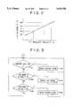
- FIG. 2is a diagram illustration a relationship between an angular velocity and a voltage output in the angular velocity sensor the of embodiment
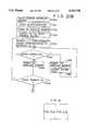
- FIG. 3is a flowchart illustrating a command code deciding operation based on a detected angular velocity of the embodiment
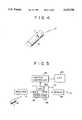
- FIG. 4is a diagram illustrating an external view of a remote commander of the embodiment
- FIG. 5is a block diagram illustrating a controller for controlling input commands corresponding to motions of the remote commander of the embodiment
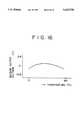
- FIG. 6is a diagram for describing an example of display of contents of an operation by the controller of FIG. 5;
- FIG. 7is a diagram illustrating a disposition of the angular velocity sensor of the embodiment.
- FIG. 8is a diagram illustrating an embodiment using an acceleration sensor according to the invention.
- FIG. 9is a diagram illustrating an embodiment using a tilt sensor according to the invention.
- FIG. 10is a diagram illustrating an embodiment using an angular displacement sensor based on a metal ball according to the invention.
- FIG. 11is a diagram illustrating a floating structure of detecting means in the embodiment of FIG. 1;
- FIG. 12comprising FIG. 12(a) and FIG. 12(b) is a diagram illustrating how the detecting means in the embodiment of FIG. 1 is held in a constant direction relative to gravity direction;
- FIG. 13is a diagram illustrating an input apparatus of the embodiment of FIG. 1 used as operating means for a game machine
- FIG. 14is a diagram illustrating the input apparatus of the embodiment of FIG. 1 used as positional displacement information input means for a virtual reality system;
- FIG. 15is a diagram illustrating the input apparatus of the embodiment of FIG. 1 used as a pointing device.
- FIG. 16is a diagram illustrating a drift characteristic of sensor output
- FIG. 17is a block diagram illustrating the input apparatus
- FIG. 18is a diagram illustrating a basic constitution of another embodiment according to the invention.
- FIG. 19is a block diagram illustrating a constitution of an input apparatus of the embodiment of FIG. 18;
- FIG. 20comprising FIG. 20(a) and FIG. 20(b) is a diagram illustrating a motion detecting signal obtained when the input apparatus of the embodiment of FIG. 1 is in a resting state;
- FIG. 21comprising FIG. 21(a) and FIG. 21(b) is a flowchart of operations of the input apparatus of the embodiment of FIG. 18.
- FIG. 1illustrates an internal constitution of the remote commander.
- Reference numeral 1indicates an oscillation gyroscope used as the angular velocity sensor.
- the oscillation gyroscopeis characterized in that applying a rotational angular velocity to an oscillating object generates a Coriolis force F, which is expressed as follows:
- An oscillation gyroscope 1is provided with driving piezoelectric ceramics 1a and detecting piezoelectric ceramics 1b.
- the driving piezoelectric ceramics lais applied with an alternating signal, which is an output of an oscillator 2.
- a Coriolis force Fis applied to the detecting piezoelectric ceramics 1b, generating a voltage E.
- the minute voltage generated by the detecting piezoelectric ceramics 1bis amplified by an amplifier 3 to be converted by an analog-digital (A-D) converter 4 into a digital signal.
- A-Danalog-digital
- Reference numeral 5indicates a controller comprising a CPU 5a, ROM 5b, and RAM 5c.
- the ROM 5b and the RAM 5cstore command signals to be transmitted, respectively.
- Reference numeral 6indicates a clock oscillator.
- Reference numeral 7indicates an Enter key provided as an operator key on a remote commander 10 for example as shown in FIG. 4. Information generated by operating the Enter key 7 is also fed to the controller 5.
- the controller 5reads an Up command or a Down command from from the ROM 5b or RAM 5c depending on the digital data of voltage E coming from the A-D converter 4 and supplies the command to the transmitter 8.
- the angular velocity ⁇ applied to the oscillation gyroscope 1 and the generated voltage Eare in a proportional relationship as shown in FIG. 2. Consequently, the controller 5 compares the input voltage E (digital data) with voltage values Va, Vb, Vc, and Vd for example, allowing an output of a command code which corresponds to an operation performed on the remote commander 10 by the operator.
- the controller 5determines a command code to be generated following a sequence illustrated by the flowchart of FIG. 3.
- an Enter commandis generated unconditionally (F101, F102 of FIG. 3); in other cases, the entered voltage E (digital data) is compared with the voltage values Va, Vb, Vc, and Vd. If Vc ⁇ E ⁇ Vd, that is, if the remote commander 10 has been swayed up, the controller 5 reads the UP command from the ROM 5b or the RAM 5c (F103, F104 of FIG. 3). If Va ⁇ E ⁇ Vb, that is, if the remote commander 10 has been swayed down, the controller 5 reads the Down command (F105, F106 of FIG. 3).
- the command code generated by the controller 5is modulated by the transmitter 8 in a predetermined manner to be sent to the predetermined equipment as an infrared-ray signal or a radio signal.
- the remote commander 10outputs only three types of command codes, the Enter command, the Up command, and the Down command, providing an input command controller having a constitution as shown in FIG. 5 for example on a receiver side integrally with or separate from the target equipment allows many more operations than these three.
- reference numeral 21indicates a receiver for receiving a command code coming from the remote commander 10 as an infrared-ray or radio signal to convert it into an electrical signal for demodulation.
- Reference numeral 22indicates a microcomputer-based input controller to perform control based on the command code demodulated by the receiver 21. This controller has a CPU 22a, a ROM 22b, and a RAM 22c.
- Reference numeral 23indicates a graphic controller which, under control of the controller 22, supplies predetermined characters to a display device (a CRT for example) integrally formed or separately connected with the target equipment.
- Reference numeral 25is a clock oscillator.
- the input controller 22makes the graphic controller 23 display contents of operations corresponding to a VTR, a CD player, and a television, as well as a cursor K as shown in FIG. 6 on a CRT 24. Then, the input controller 22, based on the Up command or the Down command supplied from the remote commander 10, moves the cursor K on the CRT.
- the input controllerreads a command code for "VTR playback" from the ROM 22b or the RAM 22c to supply it to the transmitter 26, from which the command code is sent to a VTR equipment, not shown, as a modulated signal in the form of an infrared signal for example.
- the input command controller of FIG. 5is provided on the VTR equipment, not shown, the input controller 22 supplies the command code for "VTR playback" from a terminal 27 to a predetermined operation controller to make it execute a playback operation.
- the input controller 22holds coordinate data corresponding to a display area for the operational contents on a display screen of the CRT 24 and stores actual command codes, thereby remembering a coordinate position currently pointed at by the cursor K when it has been moved to the position by position specifying information of the Up or Down command.
- the input controller 22judges that a specification at that coordinate position has been determined and reads a command code stored as one corresponding to the coordinate position to send it to the transmitter 26 or the terminal 27.
- an output sensitivity of the UP and Down commandsmay be variable to offset a difference in remote commander swaying force between different operators.
- the amplifier 3 of the remote commander 10may be provided with a control for adjustment or a coefficient of coordinate movement may be varied for the Up and Down commands used as coordinate movement information in the controller 22 on the receiving side.
- the digital data obtained by A-D converting the voltage obtained from the oscillation gyroscope 1may be sent from the transmitter 8 without change.
- the receiving sideis constituted so that an integral value of the received voltage value data is used as a variation to move the cursor on the CRT.
- the oscillation gyroscope 1may be disposed in two units (1x, 1y) in the remote commander 10 orthogonally as movement information (angular velocity) detecting means for a vertical direction y and a horizontal direction x. That is, an angular velocity -x obtained by vertically swaying the remote commander 10 is detected to output the Up command or the Down command and an angular velocity -y obtained by horizontally swaying the remote commander 10 is detected to output a move-to-left command or a move-to-right command for example.
- controller 22 on the receiving sideis constituted so that the abovementioned vertical and horizontal operations are handled as a vertical movement and a horizontal movement of a i.e., coordinate position to be specified (coordinates at which the cursor K is displayed) to perform these operations, operator efficiency will be enhanced still further.
- the input command controller shownneed not be provided.
- the command receiving equipmentmay use command codes coming from the remote commander 10 directly as equipment control codes.
- Such a setupallows the remote commander to be used as an input apparatus having a capability equivalent to a mouse for use on a personal computer.
- the above-mentioned setupis advantageous over the mouse, which uses a roller operation as input information, in that movement information may be converted into input information for transmission without having to make the input apparatus touch a desk top or the like, requiring no such facilities.
- Another embodiment of the input apparatususes an acceleration sensor to generate position specifying information.
- a basic constitution of this embodiment as the input apparatusis generally the same as that of the embodiment of FIG. 1, with the angular velocity sensor replaced with the acceleration sensor.
- the acceleration sensoris installed in three units for example on the remote commander 10 functioning as the input apparatus; an acceleration sensor 11x disposed for detecting an acceleration of a horizontal (x direction) displacement action of the remote commander 10, an acceleration sensor 11y for detecting an acceleration of a vertical (y direction) displacement action, and an acceleration sensor 11z for detecting an acceleration of a displacement action in a direction (z direction) running generally at right angles to the x and y directions, or a back and forth direction.
- a predetermined command codeis obtained in correspondence with a vertical, horizontal, or back and forth movement performed by the operator on the remote commander 10.
- the number of acceleration sensorsmay be set according to the target equipment; it may be one, two, or four.
- a tilt sensor 12may be used for physical displacement detecting means as shown in FIG. 9.
- a predetermined codeis generated based on a tilt of the remote commander 10 in a vertical direction -y detected by the tilt sensor 12.
- a metal ball 14 rolling on a pair of rails 13may be used for physical displacement detecting means as shown in FIG. 10.
- the metal ball 14rolls to a terminal 15a or a terminal 15b to close its contact.
- a controller 5identifies which terminal has been closed and generates a predetermined command signal accordingly.
- the generated signalis output via a transmitter 8.
- the detecting means(oscillation gyroscopes 1x, 1y) are fixedly secured on the input apparatus in an orthogonal manner as shown in FIG. 11.
- a journal Jis passed through the oscillation gyroscope 1x disposed vertically for detecting a horizontal (x direction) angular velocity at an upper end to be held on bearings 15. That is, the detecting means are set, held in a floating state, inside the input apparatus. Resultantly, as shown in FIGS.
- the detecting means(the oscillation gyroscopes 1x, 1y) disposed internally are always held in a constant direction relative to the direction of gravity regardless of tilting of the input apparatus. Thus, the correct output of operator information is secured regardless of how the operator holds the input apparatus.
- a detecting means floating structureis not restricted to the abovementioned bearing type.
- the embodiments of the present inventionfind applications not only in a remote commander for electronic equipment such as AV equipment and air-conditioning equipment and an input apparatus equivalent to a mouse for personal computers but also in an operator control for use on game playing equipment.
- a remote commander for electronic equipmentsuch as AV equipment and air-conditioning equipment and an input apparatus equivalent to a mouse for personal computers
- an operator control for use on game playing equipmentFor example, as shown in FIG. 13, a car racing game is displayed with a car and a steering wheel which is operated by swaying the input apparatus containing the angular velocity sensor circularly in horizontal directions.
- three acceleration sensors for generating three-dimensional displacement information in x, y, z directionsare constituted as the input apparatus for use on so-called virtual reality equipment to convert motions of the operator hand holding the input apparatus into information of movements in x, y, z directions.
- a simulation of a hand for exampleis displayed on the screen of the equipment.
- each embodimentis suitably used for a pointing device.
- a conventional rod-antenna type pointer or a laser pointeris sometimes inconvenient in that the pointer may not reach a desired position, a presenter may intercept a presentation screen or the presenter may have a hard time to keep the pointer settled at a certain position while making a verbal description, by way of example.
- the present invention embodied as a pointing devicecan eliminate such inconveniences by moving the cursor K to a desired position on the screen as the pointer.
- the input apparatusoutputs as operator information the position specifying information obtained by detecting input apparatus's physical displacement, movement velocity, or acceleration to generate a predetermined command signal corresponding to movements of a human being for example, thereby providing the input apparatus excellent in both operator efficiency and human interface.
- the embodiments according to the present inventionalso allow providing the position specifying information correctly reflecting the movements of the operator's hand holding the input apparatus regardless of how it is held in the operator's hand because the detecting means are held in the floating state inside the input apparatus to be always kept in a constant direction relative to the direction of gravity.
- the outputs of the above-mentioned sensors for detecting movements of the input apparatusare affected by a drift generally caused by a temperature variation or the like, making it difficult to use such sensors as accurate input operation detecting means.
- an input apparatusprovided with an angular velocity sensor or an acceleration sensor to output input information according to its movements in space
- the output of the sensorhas a temperature characteristic as shown in FIG. 16 when the input apparatus in a resting state.
- an input apparatus using an angular velocity sensoris constituted as shown in FIG. 17.
- an output of sensor 40is at a minute level
- the outputis amplified by an amplifying portion 41 to be converted by an A-D converter 42 into digital data for transmission to a microcomputer 43.
- the microcomputer 43Based on the digital data, the microcomputer 43 generates data to be entered in predetermined equipment to sent it to a transmitter 44.
- the data generated by the microcomputeris modulated with a predetermined carrier frequency for example by the transmitter 44 to be transmitted to the predetermined equipment in the form of a radio signal or an infrared-ray signal.
- a resistor R2is set to about 10 K ohms and a resistor R3 to about 800 K ohms to allow an amplifier A1 to be used with an amplification factor of about 31.
- a time constant circuitcomprising a capacitor C1 and a resistor R1 is provided before the amplifier A1 to be AC coupled.
- the power to the sensormust be always kept turned on or the input apparatus must be stored in a location where there is little exposure to temperature variation.
- such measuresincrease the power consumption of the sensor 40 to a relatively large extent, making the input apparatus not suitable for a battery-driven application.
- the capacitor C1is removed to improve the stabilization time, a drift of about 1 V is generated in the output of the sensor 40 as shown in FIG. 16. If the output is amplified by the amplifier A1 having an amplification factor of about 31, the drift will result in about 30 V, making the input apparatus impractical when it performs a drive of about ⁇ 2.5 V with a battery or about ⁇ 15 V with a commercial power supply.
- the input apparatusis constituted as shown in FIG. 18 for example.
- a driftoccurs in the output of the sensor 30 at itself, amplifying portion 31, and an A-D converter 32.
- a touch sensor 36for example is provided as motion stop detecting means.
- a microcomputer 33comprising a CPU 33a, a ROM 33b, and a RAM 33c detects that the input apparatus is in a resting state, or it is not held by the operator.
- a value representing a movement to be entered in the microcomputer 33 via the A-D converter 32should be equal to a reference value (for example, 0 V).
- the microcomputer 33applies a certain level of voltage to an input stage of an amplifier A2 via a D-A converter 35.
- a movement detect value coming from the A-D converter 32should be equal to the reference value (for example 0 V); actually, however, a drift may prevent the value from reaching the reference.
- a correction voltageis output while gradually incrementing the movement detect value via the D-A converter 35 to be superimposed on the detection output.
- the value of the output from the A-D converter 32reaches the reference value at a certain point. That is, the value which is output via the D-A converter 35 at the time the value output from the A-D converter 32 has reached the reference value becomes a drift correction value. The influence of the drift can be eliminated by this drift correction value.
- the sensor 30 and the amplifying portion 31can be DC-coupled with a resistor R4 to require no time constant circuit, improving the stabilization time.
- temperature detecting means 37may be provided to feed temperature information to the microcomputer 33 at certain intervals of time for example.
- the microcomputer 33is provided with storage means 33c for storing the temperature information to compare newly fed temperature information with the stored temperature information, determining a temperature variation if any. This setup allows determining a suitable correction amount based on the detected temperature variation, again eliminating the influence of drift.
- the detection output control means(that is, the microcomputer 33) is also adapted to supply a drive power to the movement detecting means (the sensor 30, the amplifying portion 31, and the A-D converter 32) when a temperature variation has been detected inside the input apparatus, that is, the correction value needs to be set.
- the detection output control meansneed not supply the drive power at other times, that is, when the input apparatus is in the resting state, reducing the power consumption.
- the input apparatusis provided with operator means (38) for operating the output of code information (the Enter code) for establishing input information entered in predetermined equipment on the side thereof in correspondence with the detection output from the movement detecting means (30, 31, and 32), they need not operate during an Enter operation and therefore require no drive power, enhancing power saving.
- code informationthe Enter code
- FIG. 19shows a constitution of the remote commander 10 having the oscillation gyroscopes 1x and 1y as shown in FIG. 7.
- An output voltage from the oscillation gyroscope 1xis amplified by an amplifying portion 3x to be digitized by an A-D converter 4x into a voltage value Ex.
- the output of the oscillation gyroscope 1xis DC-coupled via a resistor R11 to be entered in an amplifier A11.
- the amplifier A11is set with an amplification factor of about 31 by setting a resistor R12 to about 10 K ohms and a resistor R13 to about 300 K ohms for example.
- an output voltage from the oscillation gyroscope 1yis amplified by an amplifying portion 3y to be digitized by an A-D converter 4y into a voltage value Ey.
- the output from the oscillation gyroscope 1yis DC-coupled via a resistor R15 to be entered in an amplifier A12.
- the amplifier A12is set with an amplification factor of about 31 by setting a resistor R16 to about 10 K ohms and a resistor R17 to about 300 K ohms for example.
- Reference numeral 5indicates a controller comprising a microcomputer having a CPU 5a, a ROM 5b, and a RAM 5c.
- the ROM 5b or the RAM 5cstores command signals to be transmitted.
- Reference numeral 5dindicates a clock oscillator.
- the voltage value Exis supplied from the A-D converter 4x and the voltage value Ey from the A-D converter 4y.
- the voltage values Ex and Eyare values equivalent to angular velocities obtained by swaying the input apparatus in x and y directions, respectively. That is, they provide movement information of x and y directions, respectively.
- the controller 5reads an x-direction Up command or an x-direction Down command from the ROM 5b or RAM 5c according to the entered voltage value Ex and reads a y-direction Up command or a y-direction Down command according to the entered voltage value Ey and sends the read commands to a transmitter 8 as command codes.
- the command codes generated by the controller 5are modulated by the transmitter 8 in a predetermined manner to be transmitted to the predetermined target equipment in the form of an infrared-ray signal or a radio signal.
- An interrupt timer 6supplies an interrupt signal to the controller 5 at predetermined intervals of time.
- Reference numerals 9x and 9yindicate D-A converters respectively for converting corrected voltage values Dx and Dy coming from the controller 5 into analog values.
- the analog voltage from the D-A converter 9xis applied to the amplifier A11 via a resistor R14, that is, superimposed on the output voltage from the oscillation gyroscope 1x.
- the analog voltage from the D-A converter 9yis superimposed on the output voltage from the oscillation gyroscope 1y via a resistor R18 to be applied to the amplifier A12.
- Reference numeral 11is a touch sensor for detecting a state in which the remote commander 10 is held by the operator. A resultant detection signal is sent to the controller 5.
- the touch sensor 11functions as means for turning on/off the operating power of the remote commander 10 and, at the same time, functions as means for detecting that the remote commander 10 is in a resting state.
- the controller 5turns on the operating power to the remote commander 10 when the touch sensor 11 has detected an operator's holding of the remote commander 10 to make it operate as the command code input apparatus for remote control as mentioned above.
- the controller 5turns off the power to the commander. That is, the touch sensor 11 works as a power on/off switch.
- the controller 5determines the resting state, allowing the touch sensor 11 to work as a resting state detecting means. If the touch sensor 11 is not provided as the resting state detecting means, the controller 5 can be provided with a monitor capability for monitoring for the input voltage values Ex and Ey, making the capability serve as the resting state detecting means. That is, when the remote commander 10 is left untouched on a desktop, for example, in a complete resting state, the voltages values Ex and Ey do not change at all in terms of time as shown in FIG.
- the resting state detecting meansis provided because setting a drift correction value to be described must be performed in the resting state.
- Reference numeral 12indicates a temperature sensor for detecting a temperature internal to the remote commander 10.
- An output (a voltage corresponding to the detected temperature) from the temperature sensor 2is digitized by an A-D converter 13 to be fed to the controller 5 as temperature data.
- V1is a power line for feeding a supply voltage to the oscillation gyroscopes 1x and 1y, amplifying portions 3x and 3y, A-D converters 4x and 4y, and D-A converters 9x and 9y.
- V2is a power line for feeding a supply voltage to the temperature sensor 12 and the A-D converter 13.
- FIG. 21Processing shown in FIG. 21 is performed when an interrupt pulse is entered in the controller 5 by the interrupt timer 6 at an interval of 10 minutes for example (F200), FIG. 21A or when the touch sensor 11 has detected the holding of the remote commander 10 by the operator (F300), FIG. 21B.
- interrupt pulse intervalmay be shortened to five minutes for example to reduce an effect of the temperature variation.
- the interrupt timer 6may be provided externally to the controller 5 or may be constituted by an internal timer of the controller 5.
- the controller 5performs an activating operation (F201). It then turns on the power line V2 to turn on the temperature sensor 12 and the A-D converter 13 (F202).
- the controller 5captures current temperature data from the temperature sensor 12 via the A-D converter 13 to store it in the RAM 5c (F203).
- the RAM 5cmust store previously captured temperature data and therefore have storage areas arranged so that at least the previously captured data and the currently captured data are stored.
- step F204If the capture of temperature data is a first one (performed immediately after data backup was lost by battery replacement on the remote commander 10 or immediately after fabrication thereof) or data stored in the RAM 5c has been lost for some reason, the processing starts with step F204 and proceeds to F207.
- step F205compares it with the currently captured data to obtain a variation. If the temperature variation is found falling in an allowable range, the processing proceeds from step F205 to step F206, turning off the power line V2 to cut the power to the temperature sensor 12 and the A-D converter 13.
- the controller 5enters a backup mode in which the data in the RAM 5c is held, turning off the operating power (this is called a standby state) (F215).
- the controller 5waits for a next interrupt (F216).
- step F204If the previously captured temperature data is not available in step F204 or if a temperature variation exceeding the allowable range is found in step F205, the processing goes to correction value determination processing for correcting a drift in the angular velocity sensor.
- the controller 5turns on the power line V1 to apply the power voltage to the angular velocity sensor, that is, the oscillation gyroscopes 1x and 1y, the amplifying portions 3x and 3y, the A-D converters 4x and 4y, and the D-A converters 9x and 9y (F207). Then, the controller 5 sets correction values Dx and Dy to be output to the D-A converters 9x and 9y to initial values (F208).
- the controller 5first supplies the correction value Dx to the D-A converter 9x by incrementing it from its initial setting to monitor for the voltage value Ex entered from the A-D converter 4x (F209, F210). If the output of the oscillation gyroscope 1x has no drift, the voltage value Ex to be detected should be 0 V; if the output has a drift, the voltage value does not get 0 V. However, when the voltage value is superimposed on the detection output by gradually varying the correction value Dx, the voltage value Ex gets 0 V at a certain point of time. That is, at this time, the correction value Dx becomes a correction value that realizes drift correction of the oscillation gyroscope 1x at a temperature at that point of time.
- the controller 5determines a correction value for the output of the oscillation gyroscope 1y. That is, the controller 5 supplies the correction value Dy to the D-A converter 9y by incrementing it from its initial setting to monitor for the voltage value Ey entered from the A-D converter 4y (F211, F212). Then, the controller 5 uses the correction value Dy obtained when the voltage value Ey has reached 0 V as a correction value that realizes drift correction of the output of the oscillation gyroscope 1y at a temperature at voltage values having reached 0 V.
- the controller 5Upon determination of the correction values that realize drift correction, the controller 5 stores them in the RAM 5c (F213). It should be noted that, since the corrected and entered voltage values Ex and Ey involve a certain amount of offset, the controller 5 also stores it along with the corrected values.
- the controller 5Having stored the correction values Dx and Dy, the controller 5 turns off the power lines V1 and V2 to turn off the temperature sensor 12, A-D converter 13, the oscillation gyroscopes 1x and 1y, the amplifying portions 3x and 3y, A-D converters 4x and 4y, and the D-A converters 9x and 9y (F214). Then, the controller 5 enters the backup mode (F215) to wait for a next interrupt (F216).
- steps F200 through F216Processing of steps F200 through F216 is thus performed at a predetermined time interval based on the interrupt timer 6, always holding in the RAM 5c the correction values with which drift correction can be made according to the temperature state.
- an interrupt signal from the touch sensorcauses the processing subsequent to step F300 (FIG. 21A) to start.
- the controller 5receives the interrupt pulse from the touch sensor, the controller 5 first performs an activating operation (F301). Then, the controller 5 turns on the power line V1 to activate the angular velocity sensor (F302).
- the controller 5reads the correction values Dx and Dy from the RAM 5c to send them to the D-A converters 9x and 9y (F304). Since these correction values were determined, by the processing from step F202 to step F215, suitable for a temperature state at least ten minutes before, the controller 5 superimposes the voltage resulting from these correction values over the output voltage of the oscillation gyroscopes 1x and 1y to supply a resultant voltage to the amplifiers All and A12, eliminating the drift caused by a temperature characteristic. At the same time, the voltage values Ex and Ey providing movement detection values to be entered in the controller 5 are cleared of the influence of the drift.
- the controller 5then outputs a command code which provides the position specifying information in x and y direction according to the entered voltage values Ex and Ey (F304).
- step F305When the Enter key 7 has been pressed, the processing proceeds from step F305 to step F360 to turn off the power line V1. This is because, during an Enter key operation, no angular velocity need to be detected. Then, the controller 5 reads the Enter command from the ROM 5b or the RAM 5c to send it to the transmitter 8 which transmits the Enter command to the predetermined target equipment (F307).
- step F305the processing proceeds from step F305 to step F308. If the power line V1 has been turned off at the Enter operation, it is turned on again to supply the power to the angular velocity sensor for operation.
- the controller 5continues the command code output operation according to this angular velocity detection or Enter operation until the touch sensor 11 detects the operator's letting go of the remote commander 10, realizing remote control over the predetermined target equipment (loop processing F304 through F309).
- step F309the processing proceeds from step F309 to step F202. If, as mentioned above, a variation is found between the current temperature and the stored temperature, the controller 5 determines correction values and store them as the new correction values Dx and Dy. If no variation is found, the controller 5 does not update the correction values Dx and Dy, turns off the power lines V1 and V2, and enters in the backup mode to wait for a next interrupt (F202 through F216).
- drift correctionis performed by using the correction values to ensure the proper command output operation. Additionally, since no CR time constant circuit is provided for drift correction, the time for the above-mentioned operation to be stabilized is significantly shortened.
- the temperature sensoris powered off by the power line V2 only when the interrupt timer has caused an interrupt or the operator has let go of the remote commander 10.
- the angular velocity sensoris powered on by the power line V1 only when the operator is operating the remote commander 10 or the controller 5 is determining the correction values Dx and Dy. Additionally, the angular velocity sensor is kept powered off during an Enter operation even when the operator is operating the remote commander 10.
- the angular velocity sensor and the temperature sensorare supplied with the power only during a minimum necessary period, saving the power significantly.
- This power-saving constitutionmakes the remote commander suitable for being driven by a battery. It will be apparent that the power saving by frequently performing the power on/off operation on the angular velocity sensor as mentioned above functions effectively because of the realization of drift cancellation without using a time constant circuit to eliminate the otherwise instable initial operation.
- the controlleris adapted to calculate averages of the voltage values Ex and Ey to be entered into it into a certain period of time and use the averages to forecast a voltage value (an amount of drift) in the resting state.
- the controlleris further adapted to further adjust the correction values Dx and Dy accordingly, making the remote commander suitable for a long hour use.
- the temperature sensormay be turned on at a certain time interval even during use to adjust the correction values Dy and Dy accordingly.
- the drift correction values Dx and Dy at certain temperatures and the corrected voltage values Ex and Eymay be stored in the RAM 5c in the form of a data table in correspondence with temperature data.
- the correction values Dx and Dy and the corresponding voltage values Ex and Eyare stored in the form of a-table so that they correspond to the temperature data in the processing of the abovementioned steps F208 through F213. If this operation is performed, using the remote commander for several days can store most of the data on the correction values in necessary temperature states. For a temperature for which the corresponding correction values Dx and Dy have once determined, no subsequent correction value determination need be executed, further enhancing power saving. When the operator uses the remote commander, the controller detects temperature data at that time and reads the corresponding correction values to put them out.
- an acceleration sensor or a pressure sensormay be used for detecting a movement of the input apparatus in space or a movement applied thereto.
- the input apparatusis available as a remote commander for electronic equipment such as AV equipment and air conditioning equipment, an input apparatus equivalent to a mouse for personal computers, and an operator control for game playing equipment.
- the sensor output drift cancel technique according to the present inventionmay be widely applied to attitude control mechanisms for use on a car navigation system, crane trucks, machine tools, and the like.
Landscapes
- Engineering & Computer Science (AREA)
- General Engineering & Computer Science (AREA)
- Theoretical Computer Science (AREA)
- Human Computer Interaction (AREA)
- Physics & Mathematics (AREA)
- General Physics & Mathematics (AREA)
- Position Input By Displaying (AREA)
Abstract
Description
F=2mvω
Claims (5)
Applications Claiming Priority (4)
| Application Number | Priority Date | Filing Date | Title |
|---|---|---|---|
| JP4-223569 | 1992-07-31 | ||
| JP22356992AJP3218716B2 (en) | 1992-07-31 | 1992-07-31 | Input device and input system |
| JP14124893 | 1993-05-21 | ||
| JP5-141248 | 1993-05-21 |
Publications (1)
| Publication Number | Publication Date |
|---|---|
| US5453758Atrue US5453758A (en) | 1995-09-26 |
Family
ID=26473520
Family Applications (1)
| Application Number | Title | Priority Date | Filing Date |
|---|---|---|---|
| US08/098,896Expired - Fee RelatedUS5453758A (en) | 1992-07-31 | 1993-07-29 | Input apparatus |
Country Status (1)
| Country | Link |
|---|---|
| US (1) | US5453758A (en) |
Cited By (206)
| Publication number | Priority date | Publication date | Assignee | Title |
|---|---|---|---|---|
| US5590062A (en)* | 1993-07-02 | 1996-12-31 | Matsushita Electric Industrial Co., Ltd. | Simulator for producing various living environments mainly for visual perception |
| US5602569A (en)* | 1994-04-28 | 1997-02-11 | Nintendo Co., Ltd. | Controller for image processing apparatus |
| US5638092A (en)* | 1994-12-20 | 1997-06-10 | Eng; Tommy K. | Cursor control system |
| US5748180A (en)* | 1993-11-05 | 1998-05-05 | Brother Kogyo Kabushiki Kaisha | Pointing device for controlling cursor movement on display |
| US5757360A (en)* | 1995-05-03 | 1998-05-26 | Mitsubishi Electric Information Technology Center America, Inc. | Hand held computer control device |
| WO1998043203A1 (en)* | 1997-03-25 | 1998-10-01 | Ericsson Inc. | Cordless mouse-stylus-pointer |
| US5854843A (en)* | 1995-06-07 | 1998-12-29 | The United States Of America As Represented By The Secretary Of The Air Force | Virtual navigator, and inertial angular measurement system |
| US5896123A (en)* | 1995-06-16 | 1999-04-20 | Sony Corporation | Information processing method and apparatus |
| US5898421A (en)* | 1990-03-21 | 1999-04-27 | Gyration, Inc. | Gyroscopic pointer and method |
| US5902968A (en)* | 1996-02-20 | 1999-05-11 | Ricoh Company, Ltd. | Pen-shaped handwriting input apparatus using accelerometers and gyroscopes and an associated operational device for determining pen movement |
| US5907130A (en)* | 1995-08-17 | 1999-05-25 | Brother Kogyo Kabushiki Kaisha | Portable input/output device |
| US5943042A (en)* | 1994-10-07 | 1999-08-24 | International Business Machines Corporation | Control method and system for objects on a computer |
| WO1999024890A3 (en)* | 1997-11-10 | 1999-10-07 | Sc & T Int Inc | An input apparatus for a computer or game |
| US5973669A (en)* | 1996-08-22 | 1999-10-26 | Silicon Graphics, Inc. | Temporal data control system |
| US5973668A (en)* | 1995-07-21 | 1999-10-26 | Oki Electric Industry Co., Ltd. | Pointing device |
| US5990865A (en)* | 1997-01-06 | 1999-11-23 | Gard; Matthew Davis | Computer interface device |
| US6026376A (en)* | 1997-04-15 | 2000-02-15 | Kenney; John A. | Interactive electronic shopping system and method |
| US6057826A (en)* | 1993-09-02 | 2000-05-02 | Sextant Avionique | Method and device for managing the relative displacement of a cursor in relation to the image displayed on a viewing device |
| US6088023A (en)* | 1996-12-10 | 2000-07-11 | Willow Design, Inc. | Integrated pointing and drawing graphics system for computers |
| US6104380A (en)* | 1997-04-14 | 2000-08-15 | Ricoh Company, Ltd. | Direct pointing apparatus for digital displays |
| EP1035529A3 (en)* | 1998-12-07 | 2000-10-18 | Pioneer Corporation | Remote controller and navigation system for vehicle |
| US6162123A (en)* | 1997-11-25 | 2000-12-19 | Woolston; Thomas G. | Interactive electronic sword game |
| US6164808A (en)* | 1996-02-09 | 2000-12-26 | Murata Mfg. Co., Ltd. | Three-dimensional data input device |
| US6317118B1 (en)* | 1997-11-07 | 2001-11-13 | Seiko Epson Corporation | Remote coordinate input device and remote coordinate input method |
| EP1184827A3 (en)* | 2000-09-01 | 2002-04-10 | Applied Psychology Research Limited | Arm mounted remote controller |
| US6373235B1 (en)* | 1999-05-04 | 2002-04-16 | Clifford A. Barker | Apparatus and method for determining the position and motion of an object and for precise measurement of phase-related values |
| US6375572B1 (en) | 1999-10-04 | 2002-04-23 | Nintendo Co., Ltd. | Portable game apparatus with acceleration sensor and information storage medium storing a game progam |
| WO2001040807A3 (en)* | 1999-12-02 | 2002-05-02 | Koninkl Philips Electronics Nv | Movement-dependent remote control device |
| US20020078457A1 (en)* | 2000-12-20 | 2002-06-20 | Nishikawa Yuko S. | System and method for providing channel selection in an electronic programming guide |
| WO2002056165A1 (en)* | 2001-01-10 | 2002-07-18 | Sony Corporation | Information processing terminal |
| WO2002071324A1 (en)* | 2001-03-05 | 2002-09-12 | Fraunhofer-Gesellschaft zur Förderung der angewandten Forschung e.V. | Method and device for tracking an object |
| US6488583B1 (en) | 2000-04-03 | 2002-12-03 | Mitsubishi Electric Research Laboratories, Inc. | Game playing with individual anonymous laser pointers |
| US6498471B2 (en) | 1999-05-04 | 2002-12-24 | A. Clifford Barker | Apparatus and method for direct digital measurement of electrical properties of passive components |
| US20030022716A1 (en)* | 2001-07-24 | 2003-01-30 | Samsung Electronics Co., Ltd. | Input device for computer games including inertia sensor |
| US20030028688A1 (en)* | 2001-04-10 | 2003-02-06 | Logitech Europe S.A. | Hybrid presentation controller and computer input device |
| US6556185B2 (en)* | 1996-08-05 | 2003-04-29 | Sony Corporation | Information processing device and method |
| US20030081182A1 (en)* | 1995-04-07 | 2003-05-01 | Seiko Epson Corporation | Image projection system and a method of controlling a projected pointer |
| US6573883B1 (en)* | 1998-06-24 | 2003-06-03 | Hewlett Packard Development Company, L.P. | Method and apparatus for controlling a computing device with gestures |
| US6597342B1 (en)* | 1998-11-13 | 2003-07-22 | Aruze Corporation | Game machine controller |
| US20030142065A1 (en)* | 2002-01-28 | 2003-07-31 | Kourosh Pahlavan | Ring pointer device with inertial sensors |
| US6607443B1 (en)* | 1997-11-12 | 2003-08-19 | Kabushiki Kaisha Sega Enterprises | Game device |
| US20040017357A1 (en)* | 2000-08-29 | 2004-01-29 | Masahiro Kinoshita | Pointing device |
| US20040029640A1 (en)* | 1999-10-04 | 2004-02-12 | Nintendo Co., Ltd. | Game system and game information storage medium used for same |
| US20040087348A1 (en)* | 1998-10-30 | 2004-05-06 | Desch David Alan | Systems, methods, and apparatus for simultaneous viewing of differing video program sources |
| US6781570B1 (en)* | 2000-11-09 | 2004-08-24 | Logitech Europe S.A. | Wireless optical input device |
| US20040224777A1 (en)* | 2001-09-28 | 2004-11-11 | Shuffle Master, Inc. | Card shuffler with reading capability integrated into multiplayer automated gaming table |
| US6831632B2 (en) | 2001-04-09 | 2004-12-14 | I. C. + Technologies Ltd. | Apparatus and methods for hand motion tracking and handwriting recognition |
| FR2858073A1 (en)* | 2003-07-24 | 2005-01-28 | Adentis | Image display device e.g. computer, controlling system, has processing device determining commands to be applied based on acceleration measurements of control device, where commands have acceleration and command activation information |
| US20050035548A1 (en)* | 2002-10-15 | 2005-02-17 | Shuffle Master, Inc. | Interactive simulated blackjack game with side bet apparatus and in method |
| US20050073102A1 (en)* | 2002-12-04 | 2005-04-07 | Shuffle Master, Inc. | Interactive simulated baccarat side bet apparatus and method |
| WO2005040991A2 (en) | 2003-10-23 | 2005-05-06 | Hillcrest Laboratories, Inc. | User interface devices and methods employing accelerometers |
| US6908386B2 (en) | 2002-05-17 | 2005-06-21 | Nintendo Co., Ltd. | Game device changing sound and an image in accordance with a tilt operation |
| US20050164759A1 (en)* | 2004-01-26 | 2005-07-28 | Shuffle Master, Inc. | Electronic gaming machine with architecture supporting a virtual dealer and virtual cards |
| US20050162389A1 (en)* | 2002-04-12 | 2005-07-28 | Obermeyer Henry K. | Multi-axis joystick and transducer means therefore |
| US20050164762A1 (en)* | 2004-01-26 | 2005-07-28 | Shuffle Master, Inc. | Automated multiplayer game table with unique image feed of dealer |
| US20050188583A1 (en)* | 2004-02-17 | 2005-09-01 | Jackson Charles L. | Equipment operator personalization device |
| WO2005108119A2 (en) | 2004-04-30 | 2005-11-17 | Hillcrest Laboratories, Inc. | Free space pointing devices with tilt compensation and improved usability |
| US20050255918A1 (en)* | 2004-05-11 | 2005-11-17 | Riggs Andrew J | Game controller with sensitivity adjustment |
| US20060007115A1 (en)* | 2002-07-31 | 2006-01-12 | Sharp Kabushiki Kaisha | Display device for presentation |
| US20060028446A1 (en)* | 2004-04-30 | 2006-02-09 | Hillcrest Communications, Inc. | Methods and devices for removing unintentional movement in free space pointing devices |
| US20060178212A1 (en)* | 2004-11-23 | 2006-08-10 | Hillcrest Laboratories, Inc. | Semantic gaming and application transformation |
| US20060197745A1 (en)* | 2005-03-01 | 2006-09-07 | Seiko Epson Corporation | Remote control device and display control device |
| US20060239471A1 (en)* | 2003-08-27 | 2006-10-26 | Sony Computer Entertainment Inc. | Methods and apparatus for targeted sound detection and characterization |
| US20060250353A1 (en)* | 2005-05-09 | 2006-11-09 | Taizo Yasutake | Multidimensional input device |
| EP1276073A3 (en)* | 2001-07-04 | 2006-11-15 | Fraunhofer-Gesellschaft zur Förderung der angewandten Forschung e.V. | Wireless interaction system for virtual reality applications |
| US20060256081A1 (en)* | 2002-07-27 | 2006-11-16 | Sony Computer Entertainment America Inc. | Scheme for detecting and tracking user manipulation of a game controller body |
| US20060264258A1 (en)* | 2002-07-27 | 2006-11-23 | Zalewski Gary M | Multi-input game control mixer |
| US20060264259A1 (en)* | 2002-07-27 | 2006-11-23 | Zalewski Gary M | System for tracking user manipulations within an environment |
| US20060264260A1 (en)* | 2002-07-27 | 2006-11-23 | Sony Computer Entertainment Inc. | Detectable and trackable hand-held controller |
| US20060269072A1 (en)* | 2003-08-27 | 2006-11-30 | Mao Xiao D | Methods and apparatuses for adjusting a listening area for capturing sounds |
| US20060269073A1 (en)* | 2003-08-27 | 2006-11-30 | Mao Xiao D | Methods and apparatuses for capturing an audio signal based on a location of the signal |
| US20060274032A1 (en)* | 2002-07-27 | 2006-12-07 | Xiadong Mao | Tracking device for use in obtaining information for controlling game program execution |
| US20060274911A1 (en)* | 2002-07-27 | 2006-12-07 | Xiadong Mao | Tracking device with sound emitter for use in obtaining information for controlling game program execution |
| US20060282873A1 (en)* | 2002-07-27 | 2006-12-14 | Sony Computer Entertainment Inc. | Hand-held controller having detectable elements for tracking purposes |
| US20060287084A1 (en)* | 2002-07-27 | 2006-12-21 | Xiadong Mao | System, method, and apparatus for three-dimensional input control |
| US20060287087A1 (en)* | 2002-07-27 | 2006-12-21 | Sony Computer Entertainment America Inc. | Method for mapping movements of a hand-held controller to game commands |
| US20060287085A1 (en)* | 2002-07-27 | 2006-12-21 | Xiadong Mao | Inertially trackable hand-held controller |
| US7161578B1 (en) | 2000-08-02 | 2007-01-09 | Logitech Europe S.A. | Universal presentation device |
| US7164432B1 (en) | 1999-04-30 | 2007-01-16 | Sony Corporation | Information processing apparatus and method therefor, and medium |
| US20070015559A1 (en)* | 2002-07-27 | 2007-01-18 | Sony Computer Entertainment America Inc. | Method and apparatus for use in determining lack of user activity in relation to a system |
| US20070015558A1 (en)* | 2002-07-27 | 2007-01-18 | Sony Computer Entertainment America Inc. | Method and apparatus for use in determining an activity level of a user in relation to a system |
| US20070018393A1 (en)* | 2005-07-07 | 2007-01-25 | Mattel, Inc. | Methods of playing drawing games and electronic game systems adapted to interactively provide the same |
| US20070042823A1 (en)* | 2003-09-15 | 2007-02-22 | Sk Telecom Co., Ltd. | Mobile telecommunication terminal having electrical compass module and playing network type mobile game method using electrical compass module thereof |
| US20070060336A1 (en)* | 2003-09-15 | 2007-03-15 | Sony Computer Entertainment Inc. | Methods and systems for enabling depth and direction detection when interfacing with a computer program |
| WO2007045021A1 (en)* | 2005-10-17 | 2007-04-26 | Diversionary Therapy Technologies Pty Ltd | Diversionary therapy apparatus and methods and interactive devices |
| US20070113207A1 (en)* | 2005-11-16 | 2007-05-17 | Hillcrest Laboratories, Inc. | Methods and systems for gesture classification in 3D pointing devices |
| US20070129152A1 (en)* | 2005-12-01 | 2007-06-07 | Industrial Technology Research Institute | Input device and method for shooting games |
| WO2005110569A3 (en)* | 2004-05-11 | 2007-06-28 | Radica Games Ltd | Game controller with sensitivity adjustment |
| US20070149282A1 (en)* | 2005-12-27 | 2007-06-28 | Industrial Technology Research Institute | Interactive gaming method and apparatus with emotion perception ability |
| US20070155462A1 (en)* | 2003-07-22 | 2007-07-05 | O'halloran Terry | Side bets in casino wagering "war" game |
| US20070247425A1 (en)* | 2004-04-30 | 2007-10-25 | Hillcrest Laboratories, Inc. | Methods and devices for identifying users based on tremor |
| US20070252813A1 (en)* | 2004-04-30 | 2007-11-01 | Hillcrest Laboratories, Inc. | 3D pointing devices and methods |
| US20080015031A1 (en)* | 2006-05-01 | 2008-01-17 | Nintendo Co., Ltd., | Game program and game apparatus |
| US20080051197A1 (en)* | 2006-08-15 | 2008-02-28 | Mark Jawad | Systems and methods for reducing jitter associated with a control device |
| US20080080789A1 (en)* | 2006-09-28 | 2008-04-03 | Sony Computer Entertainment Inc. | Object detection using video input combined with tilt angle information |
| US20080096654A1 (en)* | 2006-10-20 | 2008-04-24 | Sony Computer Entertainment America Inc. | Game control using three-dimensional motions of controller |
| US20080096657A1 (en)* | 2006-10-20 | 2008-04-24 | Sony Computer Entertainment America Inc. | Method for aiming and shooting using motion sensing controller |
| US20080098448A1 (en)* | 2006-10-19 | 2008-04-24 | Sony Computer Entertainment America Inc. | Controller configured to track user's level of anxiety and other mental and physical attributes |
| US7367563B2 (en) | 1993-02-25 | 2008-05-06 | Shuffle Master, Inc. | Interactive simulated stud poker apparatus and method |
| US20080129691A1 (en)* | 1996-07-05 | 2008-06-05 | Armstrong Brad A | Image Controller |
| CN100399246C (en)* | 2003-12-17 | 2008-07-02 | 乐金电子(中国)研究开发中心有限公司 | Input device and method for mobile communication terminal |
| US20080192070A1 (en)* | 2002-02-07 | 2008-08-14 | Microsoft Corporation | Manipulating objects displayed on a display screen |
| US20080210653A1 (en)* | 2005-10-10 | 2008-09-04 | Wolfgang Brendel | Radio Remote Control Device for a Working Machine |
| US20080227545A1 (en)* | 2007-03-14 | 2008-09-18 | Nam Chin Cho | Apparatus and method for digitization of human motion for virtual gaming |
| US7445550B2 (en) | 2000-02-22 | 2008-11-04 | Creative Kingdoms, Llc | Magical wand and interactive play experience |
| WO2007130872A3 (en)* | 2006-05-04 | 2008-11-20 | Sony Comp Entertainment Us | Method and apparatus for use in determining lack of user activity, determining an activity level of a user, and/or adding a new player in relation to a system |
| US20080303697A1 (en)* | 2007-06-06 | 2008-12-11 | Sony Corporation | Input apparatus, control apparatus, control system, control method, and program therefor |
| US20090009471A1 (en)* | 2007-07-04 | 2009-01-08 | Sony Corporation | Input apparatus, control apparatus, control system, and control method |
| US20090033807A1 (en)* | 2007-06-28 | 2009-02-05 | Hua Sheng | Real-Time Dynamic Tracking of Bias |
| US7500917B2 (en) | 2000-02-22 | 2009-03-10 | Creative Kingdoms, Llc | Magical wand and interactive play experience |
| US20090100373A1 (en)* | 2007-10-16 | 2009-04-16 | Hillcrest Labroatories, Inc. | Fast and smooth scrolling of user interfaces operating on thin clients |
| US20090115724A1 (en)* | 2007-10-22 | 2009-05-07 | Sony Corporation | Three-dimensional operation input apparatus, control apparatus, control system, control method, method of producing a three-dimensional operation input apparatus, and handheld apparatus |
| US20090122146A1 (en)* | 2002-07-27 | 2009-05-14 | Sony Computer Entertainment Inc. | Method and apparatus for tracking three-dimensional movements of an object using a depth sensing camera |
| DE102007060007A1 (en)* | 2007-12-13 | 2009-06-18 | BSH Bosch und Siemens Hausgeräte GmbH | Control device for a domestic appliance, a domestic appliance with an operating device, and a method for operating a domestic appliance |
| US20090183567A1 (en)* | 2006-09-21 | 2009-07-23 | Sony Computer Entertainment Inc. | Operation device control apparatus, operation device control method, information storage medium, and operation device |
| US20090195501A1 (en)* | 2008-02-05 | 2009-08-06 | Chin-Chung Kuo | Handheld pointing device, pointing method thereof and method for improving static drift |
| US20090201249A1 (en)* | 2007-12-07 | 2009-08-13 | Sony Corporation | Input apparatus, control apparatus, control system, and handheld apparatus |
| US20090259432A1 (en)* | 2008-04-15 | 2009-10-15 | Liberty Matthew G | Tracking determination based on intensity angular gradient of a wave |
| US20090262073A1 (en)* | 2008-04-21 | 2009-10-22 | Matsushita Electric Industrial Co., Ltd. | Touch sensitive remote control system that detects hand size characteristics of user and adapts mapping to screen display |
| US20090267898A1 (en)* | 2008-04-24 | 2009-10-29 | Sony Corporation | Input apparatus and control system |
| US20090285443A1 (en)* | 2008-05-15 | 2009-11-19 | Sony Ericsson Mobile Communications Ab | Remote Control Based on Image Recognition |
| US7623115B2 (en) | 2002-07-27 | 2009-11-24 | Sony Computer Entertainment Inc. | Method and apparatus for light input device |
| US20090295721A1 (en)* | 2008-06-02 | 2009-12-03 | Sony Corporation | Input apparatus, control apparatus, control system, and control method |
| US20090309830A1 (en)* | 2007-06-20 | 2009-12-17 | Sony Corporation | Control apparatus, input apparatus, control system, handheld information processing apparatus, control method, and program therefor |
| WO2009156499A1 (en) | 2008-06-27 | 2009-12-30 | Movea S.A | Pointer with motion sensing resolved by data merging |
| US20090326857A1 (en)* | 2008-06-27 | 2009-12-31 | Movea Sa | Hand held pointing device with roll compensation |
| US20100001953A1 (en)* | 2007-07-04 | 2010-01-07 | Sony Corporation | Input apparatus, control apparatus, control method, and handheld apparatus |
| US20100007518A1 (en)* | 2008-07-10 | 2010-01-14 | Samsung Electronics Co., Ltd | Input apparatus using motions and user manipulations and input method applied to such input apparatus |
| US20100007528A1 (en)* | 2008-07-11 | 2010-01-14 | Nintendo Co., Ltd. | Expanding operating device and operating system |
| US20100033424A1 (en)* | 2007-07-09 | 2010-02-11 | Sony Corporation | Electronic appartus and control method therefor |
| US20100045599A1 (en)* | 2008-08-22 | 2010-02-25 | Sony Corporation | Input apparatus, control apparatus, control system, and control method |
| US7674184B2 (en) | 2002-08-01 | 2010-03-09 | Creative Kingdoms, Llc | Interactive water attraction and quest game |
| US20100103095A1 (en)* | 2007-09-12 | 2010-04-29 | Sony Corporation | Input apparatus, control apparatus, control system, and control method |
| US20100103096A1 (en)* | 2007-07-06 | 2010-04-29 | Sony Corporation | Input apparatus, control apparatus, control system, control method, and handheld apparatus |
| US7716008B2 (en) | 2007-01-19 | 2010-05-11 | Nintendo Co., Ltd. | Acceleration data processing program, and storage medium, and acceleration data processing apparatus for use with the same |
| US20100156788A1 (en)* | 2008-12-18 | 2010-06-24 | Seiko Epson Corporation | Input device and data processing system |
| US20100169824A1 (en)* | 2008-12-25 | 2010-07-01 | Sony Corporation | Input apparatus, control apparatus, control system, electronic apparatus, and control method |
| US20100169843A1 (en)* | 2008-12-25 | 2010-07-01 | Sony Corporation | Input apparatus, handheld apparatus, and control method |
| US7749089B1 (en) | 1999-02-26 | 2010-07-06 | Creative Kingdoms, Llc | Multi-media interactive play system |
| US7774155B2 (en) | 2006-03-10 | 2010-08-10 | Nintendo Co., Ltd. | Accelerometer-based controller |
| US7786976B2 (en) | 2006-03-09 | 2010-08-31 | Nintendo Co., Ltd. | Coordinate calculating apparatus and coordinate calculating program |
| US20100238112A1 (en)* | 2009-03-17 | 2010-09-23 | Sony Corporation | Input apparatus, control apparatus, control system, and control method |
| US7850527B2 (en) | 2000-02-22 | 2010-12-14 | Creative Kingdoms, Llc | Magic-themed adventure game |
| US7854655B2 (en)* | 2002-07-27 | 2010-12-21 | Sony Computer Entertainment America Inc. | Obtaining input for controlling execution of a game program |
| US7874918B2 (en) | 2005-11-04 | 2011-01-25 | Mattel Inc. | Game unit with motion and orientation sensing controller |
| US7877224B2 (en) | 2006-03-28 | 2011-01-25 | Nintendo Co, Ltd. | Inclination calculation apparatus and inclination calculation program, and game apparatus and game program |
| US7878905B2 (en) | 2000-02-22 | 2011-02-01 | Creative Kingdoms, Llc | Multi-layered interactive play experience |
| US7892178B1 (en)* | 2009-09-28 | 2011-02-22 | Impact Sports Technologies, Inc. | Monitoring device for an interactive game |
| US20110043697A1 (en)* | 2009-08-18 | 2011-02-24 | Sony Corporation | Remote control, remote control method, display device and display method |
| US7927216B2 (en) | 2005-09-15 | 2011-04-19 | Nintendo Co., Ltd. | Video game system with wireless modular handheld controller |
| US7931535B2 (en) | 2005-08-22 | 2011-04-26 | Nintendo Co., Ltd. | Game operating device |
| US7942745B2 (en) | 2005-08-22 | 2011-05-17 | Nintendo Co., Ltd. | Game operating device |
| US20110229414A1 (en)* | 2010-01-27 | 2011-09-22 | Siemens Aktiengesellschaft | Contrast Agents For Detecting Protease Activity By Means Of Hyperpolarization And For Stratifying Patients |
| US20110254760A1 (en)* | 2010-04-20 | 2011-10-20 | Invensense, Inc. | Wireless Motion Processing Sensor Systems Suitable for Mobile and Battery Operation |
| CN102262437A (en)* | 2010-05-24 | 2011-11-30 | 英属维京群岛商速位互动股份有限公司 | motion sensing system |
| US8072470B2 (en) | 2003-05-29 | 2011-12-06 | Sony Computer Entertainment Inc. | System and method for providing a real-time three-dimensional interactive environment |
| US8139793B2 (en) | 2003-08-27 | 2012-03-20 | Sony Computer Entertainment Inc. | Methods and apparatus for capturing audio signals based on a visual image |
| US8157651B2 (en) | 2005-09-12 | 2012-04-17 | Nintendo Co., Ltd. | Information processing program |
| US8230610B2 (en) | 2005-05-17 | 2012-07-31 | Qualcomm Incorporated | Orientation-sensitive signal output |
| US20120232704A1 (en)* | 2011-03-08 | 2012-09-13 | Eugene Novak | System for Control of Mobile Hydraulic Equipment |
| US8267786B2 (en) | 2005-08-24 | 2012-09-18 | Nintendo Co., Ltd. | Game controller and game system |
| WO2012146315A1 (en) | 2011-04-29 | 2012-11-01 | Movea | Improved pointing device |
| US8308563B2 (en) | 2005-08-30 | 2012-11-13 | Nintendo Co., Ltd. | Game system and storage medium having game program stored thereon |
| US8310656B2 (en) | 2006-09-28 | 2012-11-13 | Sony Computer Entertainment America Llc | Mapping movements of a hand-held controller to the two-dimensional image plane of a display screen |
| US8313380B2 (en) | 2002-07-27 | 2012-11-20 | Sony Computer Entertainment America Llc | Scheme for translating movements of a hand-held controller into inputs for a system |
| US8313379B2 (en) | 2005-08-22 | 2012-11-20 | Nintendo Co., Ltd. | Video game system with wireless modular handheld controller |
| US8323106B2 (en) | 2008-05-30 | 2012-12-04 | Sony Computer Entertainment America Llc | Determination of controller three-dimensional location using image analysis and ultrasonic communication |
| US8409003B2 (en) | 2005-08-24 | 2013-04-02 | Nintendo Co., Ltd. | Game controller and game system |
| US8475252B2 (en) | 2007-05-30 | 2013-07-02 | Shfl Entertainment, Inc. | Multi-player games with individual player decks |
| US8502787B2 (en) | 2008-11-26 | 2013-08-06 | Panasonic Corporation | System and method for differentiating between intended and unintended user input on a touchpad |
| US8503086B2 (en) | 1995-11-06 | 2013-08-06 | Impulse Technology Ltd. | System and method for tracking and assessing movement skills in multidimensional space |
| US8542907B2 (en) | 2007-12-17 | 2013-09-24 | Sony Computer Entertainment America Llc | Dynamic three-dimensional object mapping for user-defined control device |
| US8556628B1 (en) | 2006-08-15 | 2013-10-15 | Malcom E. Baxter | Shooting training device |
| US8568213B2 (en) | 2005-11-04 | 2013-10-29 | Mattel, Inc. | Game unit with controller-determined characters |
| US8574050B2 (en) | 2005-11-04 | 2013-11-05 | Mattel, Inc. | Game unit with dual joystick controllers |
| US8608535B2 (en) | 2002-04-05 | 2013-12-17 | Mq Gaming, Llc | Systems and methods for providing an interactive game |
| US8629836B2 (en) | 2004-04-30 | 2014-01-14 | Hillcrest Laboratories, Inc. | 3D pointing devices with orientation compensation and improved usability |
| US8696482B1 (en) | 2010-10-05 | 2014-04-15 | Swingbyte, Inc. | Three dimensional golf swing analyzer |
| US8702515B2 (en) | 2002-04-05 | 2014-04-22 | Mq Gaming, Llc | Multi-platform gaming system using RFID-tagged toys |
| US8753165B2 (en) | 2000-10-20 | 2014-06-17 | Mq Gaming, Llc | Wireless toy systems and methods for interactive entertainment |
| WO2014101947A1 (en) | 2012-12-26 | 2014-07-03 | Movea | Method and device for sensing orientation of an object in space in a fixed frame of reference |
| US8884991B2 (en) | 2010-06-03 | 2014-11-11 | Sony Corporation | Control system, control apparatus, handheld apparatus, control method, and program |
| US8965402B2 (en) | 2012-01-19 | 2015-02-24 | University Of Southern California | Physical activity monitoring and intervention using smartphone and mobile app |
| US8992322B2 (en)* | 2003-06-09 | 2015-03-31 | Immersion Corporation | Interactive gaming systems with haptic feedback |
| US9033782B2 (en) | 1999-10-04 | 2015-05-19 | Ssd Company Limited | Sensing ball game machine |
| US9081426B2 (en) | 1992-03-05 | 2015-07-14 | Anascape, Ltd. | Image controller |
| US9151564B1 (en) | 2006-08-15 | 2015-10-06 | Triggermaster, Inc. | Firearm trigger pull training system and methods |
| US9174119B2 (en) | 2002-07-27 | 2015-11-03 | Sony Computer Entertainement America, LLC | Controller for providing inputs to control execution of a program when inputs are combined |
| US9177387B2 (en) | 2003-02-11 | 2015-11-03 | Sony Computer Entertainment Inc. | Method and apparatus for real time motion capture |
| US9211439B1 (en) | 2010-10-05 | 2015-12-15 | Swingbyte, Inc. | Three dimensional golf swing analyzer |
| US9446319B2 (en) | 2003-03-25 | 2016-09-20 | Mq Gaming, Llc | Interactive gaming toy |
| US9474968B2 (en) | 2002-07-27 | 2016-10-25 | Sony Interactive Entertainment America Llc | Method and system for applying gearing effects to visual tracking |
| US9682319B2 (en) | 2002-07-31 | 2017-06-20 | Sony Interactive Entertainment Inc. | Combiner method for altering game gearing |
| CN106959770A (en)* | 2011-03-28 | 2017-07-18 | 曦恩体感科技股份有限公司 | 3D indicating device and method for compensating rotation of 3D indicating device |
| US9728095B1 (en) | 2006-08-15 | 2017-08-08 | Triggermaster, Llc | Firearm trigger pull training system and methods |
| US9870070B2 (en) | 2008-06-27 | 2018-01-16 | Movea Sa | Hand held pointing device with roll compensation |
| US9904292B2 (en) | 2002-08-30 | 2018-02-27 | Qfo Labs, Inc. | Method for operating a radio-controlled flying hovercraft |
| US20180107290A1 (en)* | 2007-09-14 | 2018-04-19 | Sony Corporation | Input apparatus, control apparatus, control system, control method, and handheld apparatus |
| US10213645B1 (en) | 2011-10-03 | 2019-02-26 | Swingbyte, Inc. | Motion attributes recognition system and methods |
| US10279254B2 (en) | 2005-10-26 | 2019-05-07 | Sony Interactive Entertainment Inc. | Controller having visually trackable object for interfacing with a gaming system |
| US10620726B2 (en) | 2008-07-01 | 2020-04-14 | Idhl Holdings, Inc. | 3D pointer mapping |
| US10712116B1 (en) | 2014-07-14 | 2020-07-14 | Triggermaster, Llc | Firearm body motion detection training system |
| US10852846B2 (en) | 2010-01-06 | 2020-12-01 | Cm Hk Limited | Electronic device for use in motion detection and method for obtaining resultant deviation thereof |
| USRE48417E1 (en) | 2006-09-28 | 2021-02-02 | Sony Interactive Entertainment Inc. | Object direction using video input combined with tilt angle information |
| US11516528B2 (en)* | 2007-10-30 | 2022-11-29 | Samsung Electronics Co., Ltd. | Broadcast receiving apparatus and control method thereof |
| US11712637B1 (en) | 2018-03-23 | 2023-08-01 | Steven M. Hoffberg | Steerable disk or ball |
Citations (9)
| Publication number | Priority date | Publication date | Assignee | Title |
|---|---|---|---|---|
| US3782205A (en)* | 1972-11-09 | 1974-01-01 | Nasa | Temperature compensated digital inertial sensor |
| US4580006A (en)* | 1984-06-14 | 1986-04-01 | Hull Daniel T | Method and apparatus for providing two dimensional positioning data signals |
| US4601206A (en)* | 1983-09-16 | 1986-07-22 | Ferranti Plc | Accelerometer system |
| US4831544A (en)* | 1985-12-28 | 1989-05-16 | Tokyo Keiki Co., Ltd. | Attitude and heading reference detecting apparatus |
| US4839838A (en)* | 1987-03-30 | 1989-06-13 | Labiche Mitchell | Spatial input apparatus |
| US5012231A (en)* | 1988-12-20 | 1991-04-30 | Golemics, Inc. | Method and apparatus for cursor motion having variable response |
| US5288078A (en)* | 1988-10-14 | 1994-02-22 | David G. Capper | Control interface apparatus |
| US5296871A (en)* | 1992-07-27 | 1994-03-22 | Paley W Bradford | Three-dimensional mouse with tactile feedback |
| US5329276A (en)* | 1990-12-19 | 1994-07-12 | Kabushiki Kaisha Yaskawa Denki | Multidimensional signal input device |
- 1993
- 1993-07-29USUS08/098,896patent/US5453758A/ennot_activeExpired - Fee Related
Patent Citations (9)
| Publication number | Priority date | Publication date | Assignee | Title |
|---|---|---|---|---|
| US3782205A (en)* | 1972-11-09 | 1974-01-01 | Nasa | Temperature compensated digital inertial sensor |
| US4601206A (en)* | 1983-09-16 | 1986-07-22 | Ferranti Plc | Accelerometer system |
| US4580006A (en)* | 1984-06-14 | 1986-04-01 | Hull Daniel T | Method and apparatus for providing two dimensional positioning data signals |
| US4831544A (en)* | 1985-12-28 | 1989-05-16 | Tokyo Keiki Co., Ltd. | Attitude and heading reference detecting apparatus |
| US4839838A (en)* | 1987-03-30 | 1989-06-13 | Labiche Mitchell | Spatial input apparatus |
| US5288078A (en)* | 1988-10-14 | 1994-02-22 | David G. Capper | Control interface apparatus |
| US5012231A (en)* | 1988-12-20 | 1991-04-30 | Golemics, Inc. | Method and apparatus for cursor motion having variable response |
| US5329276A (en)* | 1990-12-19 | 1994-07-12 | Kabushiki Kaisha Yaskawa Denki | Multidimensional signal input device |
| US5296871A (en)* | 1992-07-27 | 1994-03-22 | Paley W Bradford | Three-dimensional mouse with tactile feedback |
Cited By (480)
| Publication number | Priority date | Publication date | Assignee | Title |
|---|---|---|---|---|
| USRE41520E1 (en) | 1990-03-21 | 2010-08-17 | Thomson Licensing | Gyroscopic pointer and method |
| US5898421A (en)* | 1990-03-21 | 1999-04-27 | Gyration, Inc. | Gyroscopic pointer and method |
| US9081426B2 (en) | 1992-03-05 | 2015-07-14 | Anascape, Ltd. | Image controller |
| US7367563B2 (en) | 1993-02-25 | 2008-05-06 | Shuffle Master, Inc. | Interactive simulated stud poker apparatus and method |
| US5590062A (en)* | 1993-07-02 | 1996-12-31 | Matsushita Electric Industrial Co., Ltd. | Simulator for producing various living environments mainly for visual perception |
| US6057826A (en)* | 1993-09-02 | 2000-05-02 | Sextant Avionique | Method and device for managing the relative displacement of a cursor in relation to the image displayed on a viewing device |
| US5748180A (en)* | 1993-11-05 | 1998-05-05 | Brother Kogyo Kabushiki Kaisha | Pointing device for controlling cursor movement on display |
| US5602569A (en)* | 1994-04-28 | 1997-02-11 | Nintendo Co., Ltd. | Controller for image processing apparatus |
| US5943042A (en)* | 1994-10-07 | 1999-08-24 | International Business Machines Corporation | Control method and system for objects on a computer |
| US5638092A (en)* | 1994-12-20 | 1997-06-10 | Eng; Tommy K. | Cursor control system |
| US20050151932A1 (en)* | 1995-04-07 | 2005-07-14 | Seiko Epson Corporation | Image projection system and a method of controlling a projected pointer |
| US20060203203A1 (en)* | 1995-04-07 | 2006-09-14 | Seiko Epson Corporation | Image projection system and a method of controlling a projected pointer |
| US8985778B2 (en) | 1995-04-07 | 2015-03-24 | Seiko Epson Corporation | Image projection system and a method of controlling a projected pointer |
| US20030081182A1 (en)* | 1995-04-07 | 2003-05-01 | Seiko Epson Corporation | Image projection system and a method of controlling a projected pointer |
| US20060077352A1 (en)* | 1995-04-07 | 2006-04-13 | Seiko Epson Corporation | Image projection system and a method of controlling a projected pointer |
| US8746893B2 (en) | 1995-04-07 | 2014-06-10 | Seiko Epson Corporation | Image projection system and a method of controlling a projected pointer |
| US5757360A (en)* | 1995-05-03 | 1998-05-26 | Mitsubishi Electric Information Technology Center America, Inc. | Hand held computer control device |
| US5854843A (en)* | 1995-06-07 | 1998-12-29 | The United States Of America As Represented By The Secretary Of The Air Force | Virtual navigator, and inertial angular measurement system |
| US5896123A (en)* | 1995-06-16 | 1999-04-20 | Sony Corporation | Information processing method and apparatus |
| US5973668A (en)* | 1995-07-21 | 1999-10-26 | Oki Electric Industry Co., Ltd. | Pointing device |
| US5907130A (en)* | 1995-08-17 | 1999-05-25 | Brother Kogyo Kabushiki Kaisha | Portable input/output device |
| US8861091B2 (en) | 1995-11-06 | 2014-10-14 | Impulse Technology Ltd. | System and method for tracking and assessing movement skills in multidimensional space |
| US8503086B2 (en) | 1995-11-06 | 2013-08-06 | Impulse Technology Ltd. | System and method for tracking and assessing movement skills in multidimensional space |
| US6164808A (en)* | 1996-02-09 | 2000-12-26 | Murata Mfg. Co., Ltd. | Three-dimensional data input device |
| US6084577A (en)* | 1996-02-20 | 2000-07-04 | Ricoh Company, Ltd. | Pen-shaped handwriting input apparatus using accelerometers and gyroscopes and an associated operational device for determining pen movement |
| US5902968A (en)* | 1996-02-20 | 1999-05-11 | Ricoh Company, Ltd. | Pen-shaped handwriting input apparatus using accelerometers and gyroscopes and an associated operational device for determining pen movement |
| US6229102B1 (en) | 1996-02-20 | 2001-05-08 | Ricoh Company, Ltd. | Pen-shaped handwriting input apparatus using accelerometers and gyroscopes and an associated operational device for determining pen movement |
| US5981884A (en)* | 1996-02-20 | 1999-11-09 | Ricoh Company, Ltd. | Pen-shaped handwriting input apparatus using accelerometers and gyroscopes and an associated operational device for determining pen movement |
| US20080129691A1 (en)* | 1996-07-05 | 2008-06-05 | Armstrong Brad A | Image Controller |
| US8674932B2 (en) | 1996-07-05 | 2014-03-18 | Anascape, Ltd. | Image controller |
| US6567068B2 (en)* | 1996-08-05 | 2003-05-20 | Sony Corporation | Information processing device and method |
| US6556185B2 (en)* | 1996-08-05 | 2003-04-29 | Sony Corporation | Information processing device and method |
| US5973669A (en)* | 1996-08-22 | 1999-10-26 | Silicon Graphics, Inc. | Temporal data control system |
| US6674425B1 (en) | 1996-12-10 | 2004-01-06 | Willow Design, Inc. | Integrated pointing and drawing graphics system for computers |
| US6088023A (en)* | 1996-12-10 | 2000-07-11 | Willow Design, Inc. | Integrated pointing and drawing graphics system for computers |
| US5990865A (en)* | 1997-01-06 | 1999-11-23 | Gard; Matthew Davis | Computer interface device |
| US7333089B1 (en) | 1997-01-06 | 2008-02-19 | Matthew Davis Gard | Computer interface device |
| WO1998043203A1 (en)* | 1997-03-25 | 1998-10-01 | Ericsson Inc. | Cordless mouse-stylus-pointer |
| US6104380A (en)* | 1997-04-14 | 2000-08-15 | Ricoh Company, Ltd. | Direct pointing apparatus for digital displays |
| DE19816147B4 (en)* | 1997-04-14 | 2005-10-20 | Ricoh Kk | Cursor control system |
| US6381583B1 (en)* | 1997-04-15 | 2002-04-30 | John A. Kenney | Interactive electronic shopping system and method |
| US6026376A (en)* | 1997-04-15 | 2000-02-15 | Kenney; John A. | Interactive electronic shopping system and method |
| US6317118B1 (en)* | 1997-11-07 | 2001-11-13 | Seiko Epson Corporation | Remote coordinate input device and remote coordinate input method |
| US6587092B2 (en) | 1997-11-07 | 2003-07-01 | Seiko Epson Corporation | Remote coordinate input device and remote coordinate input method |
| WO1999024890A3 (en)* | 1997-11-10 | 1999-10-07 | Sc & T Int Inc | An input apparatus for a computer or game |
| US6607443B1 (en)* | 1997-11-12 | 2003-08-19 | Kabushiki Kaisha Sega Enterprises | Game device |
| US7128651B2 (en) | 1997-11-12 | 2006-10-31 | Kabushiki Kaisha Sega Enterprises | Card game for displaying images based on sound recognition |
| US8777748B2 (en) | 1997-11-25 | 2014-07-15 | Kico Sound Llc | Electronic gaming device with feedback |
| US7871330B2 (en) | 1997-11-25 | 2011-01-18 | Woolston Thomas G | Electronic sword game with input and feedback |
| US20050085298A1 (en)* | 1997-11-25 | 2005-04-21 | Woolston Thomas G. | Electronic sword game with input and feedback |
| US8485903B2 (en) | 1997-11-25 | 2013-07-16 | Kico Sound Llc | Electronic gaming device with feedback |
| US20080014834A1 (en)* | 1997-11-25 | 2008-01-17 | Woolston Thomas G | Electronic sword game with input and feedback |
| US7247097B2 (en) | 1997-11-25 | 2007-07-24 | Woolston Thomas G | Electronic sword game with input and feedback |
| US6162123A (en)* | 1997-11-25 | 2000-12-19 | Woolston; Thomas G. | Interactive electronic sword game |
| US20110086709A1 (en)* | 1997-11-25 | 2011-04-14 | Kico Sound Llc | Electronic sword game with input and feedback |
| US6573883B1 (en)* | 1998-06-24 | 2003-06-03 | Hewlett Packard Development Company, L.P. | Method and apparatus for controlling a computing device with gestures |
| US20040087348A1 (en)* | 1998-10-30 | 2004-05-06 | Desch David Alan | Systems, methods, and apparatus for simultaneous viewing of differing video program sources |
| US7202915B2 (en) | 1998-10-30 | 2007-04-10 | Sony Corporation | Systems, methods, and apparatus for simultaneous viewing of differing video program sources |
| US6597342B1 (en)* | 1998-11-13 | 2003-07-22 | Aruze Corporation | Game machine controller |
| EP1035529A3 (en)* | 1998-12-07 | 2000-10-18 | Pioneer Corporation | Remote controller and navigation system for vehicle |
| US7749089B1 (en) | 1999-02-26 | 2010-07-06 | Creative Kingdoms, Llc | Multi-media interactive play system |
| US8888576B2 (en) | 1999-02-26 | 2014-11-18 | Mq Gaming, Llc | Multi-media interactive play system |
| US9861887B1 (en) | 1999-02-26 | 2018-01-09 | Mq Gaming, Llc | Multi-platform gaming systems and methods |
| US9186585B2 (en) | 1999-02-26 | 2015-11-17 | Mq Gaming, Llc | Multi-platform gaming systems and methods |
| US9731194B2 (en) | 1999-02-26 | 2017-08-15 | Mq Gaming, Llc | Multi-platform gaming systems and methods |
| US8342929B2 (en) | 1999-02-26 | 2013-01-01 | Creative Kingdoms, Llc | Systems and methods for interactive game play |
| US9468854B2 (en) | 1999-02-26 | 2016-10-18 | Mq Gaming, Llc | Multi-platform gaming systems and methods |
| US8758136B2 (en) | 1999-02-26 | 2014-06-24 | Mq Gaming, Llc | Multi-platform gaming systems and methods |
| US10300374B2 (en) | 1999-02-26 | 2019-05-28 | Mq Gaming, Llc | Multi-platform gaming systems and methods |
| US7164432B1 (en) | 1999-04-30 | 2007-01-16 | Sony Corporation | Information processing apparatus and method therefor, and medium |
| US6373235B1 (en)* | 1999-05-04 | 2002-04-16 | Clifford A. Barker | Apparatus and method for determining the position and motion of an object and for precise measurement of phase-related values |
| US6498471B2 (en) | 1999-05-04 | 2002-12-24 | A. Clifford Barker | Apparatus and method for direct digital measurement of electrical properties of passive components |
| US20040029640A1 (en)* | 1999-10-04 | 2004-02-12 | Nintendo Co., Ltd. | Game system and game information storage medium used for same |
| US9033782B2 (en) | 1999-10-04 | 2015-05-19 | Ssd Company Limited | Sensing ball game machine |
| US7601066B1 (en) | 1999-10-04 | 2009-10-13 | Nintendo Co., Ltd. | Game system and game information storage medium used for same |
| US20090325698A1 (en)* | 1999-10-04 | 2009-12-31 | Nintendo Co., Ltd. | Game system and game information storage medium used for same |
| US9138645B2 (en) | 1999-10-04 | 2015-09-22 | Nintendo Co., Ltd. | Game system and game information storage medium used for same |
| US6375572B1 (en) | 1999-10-04 | 2002-04-23 | Nintendo Co., Ltd. | Portable game apparatus with acceleration sensor and information storage medium storing a game progam |
| US7223173B2 (en) | 1999-10-04 | 2007-05-29 | Nintendo Co., Ltd. | Game system and game information storage medium used for same |
| US8562402B2 (en) | 1999-10-04 | 2013-10-22 | Nintendo Co., Ltd. | Game system and game information storage medium used for same |
| US10046231B2 (en) | 1999-10-04 | 2018-08-14 | Nintendo Co., Ltd. | Game system and game information storage medium used for same |
| US6641482B2 (en) | 1999-10-04 | 2003-11-04 | Nintendo Co., Ltd. | Portable game apparatus with acceleration sensor and information storage medium storing a game program |
| US9205332B2 (en) | 1999-10-04 | 2015-12-08 | Nintendo Co., Ltd. | Game system and game information storage medium used for same |
| US9205331B2 (en) | 1999-10-04 | 2015-12-08 | Nintendo Co., Ltd. | Mobile wireless handset and system including mobile wireless handset |
| US9579565B2 (en) | 1999-10-04 | 2017-02-28 | Nintendo Co., Ltd. | Game system and game information storage medium used for same |
| WO2001040807A3 (en)* | 1999-12-02 | 2002-05-02 | Koninkl Philips Electronics Nv | Movement-dependent remote control device |
| US6603420B1 (en) | 1999-12-02 | 2003-08-05 | Koninklijke Philips Electronics N.V. | Remote control device with motion-based control of receiver volume, channel selection or other parameters |
| US7896742B2 (en) | 2000-02-22 | 2011-03-01 | Creative Kingdoms, Llc | Apparatus and methods for providing interactive entertainment |
| US8169406B2 (en) | 2000-02-22 | 2012-05-01 | Creative Kingdoms, Llc | Motion-sensitive wand controller for a game |
| US9713766B2 (en) | 2000-02-22 | 2017-07-25 | Mq Gaming, Llc | Dual-range wireless interactive entertainment device |
| US10188953B2 (en) | 2000-02-22 | 2019-01-29 | Mq Gaming, Llc | Dual-range wireless interactive entertainment device |
| US8708821B2 (en) | 2000-02-22 | 2014-04-29 | Creative Kingdoms, Llc | Systems and methods for providing interactive game play |
| US7445550B2 (en) | 2000-02-22 | 2008-11-04 | Creative Kingdoms, Llc | Magical wand and interactive play experience |
| US7500917B2 (en) | 2000-02-22 | 2009-03-10 | Creative Kingdoms, Llc | Magical wand and interactive play experience |
| US9814973B2 (en) | 2000-02-22 | 2017-11-14 | Mq Gaming, Llc | Interactive entertainment system |
| US8790180B2 (en) | 2000-02-22 | 2014-07-29 | Creative Kingdoms, Llc | Interactive game and associated wireless toy |
| US7878905B2 (en) | 2000-02-22 | 2011-02-01 | Creative Kingdoms, Llc | Multi-layered interactive play experience |
| US9149717B2 (en) | 2000-02-22 | 2015-10-06 | Mq Gaming, Llc | Dual-range wireless interactive entertainment device |
| US8686579B2 (en) | 2000-02-22 | 2014-04-01 | Creative Kingdoms, Llc | Dual-range wireless controller |
| US10307671B2 (en) | 2000-02-22 | 2019-06-04 | Mq Gaming, Llc | Interactive entertainment system |
| US9138650B2 (en) | 2000-02-22 | 2015-09-22 | Mq Gaming, Llc | Portable tracking device for entertainment purposes |
| US9474962B2 (en) | 2000-02-22 | 2016-10-25 | Mq Gaming, Llc | Interactive entertainment system |
| US7850527B2 (en) | 2000-02-22 | 2010-12-14 | Creative Kingdoms, Llc | Magic-themed adventure game |
| US8531050B2 (en) | 2000-02-22 | 2013-09-10 | Creative Kingdoms, Llc | Wirelessly powered gaming device |
| US8814688B2 (en) | 2000-02-22 | 2014-08-26 | Creative Kingdoms, Llc | Customizable toy for playing a wireless interactive game having both physical and virtual elements |
| US8089458B2 (en) | 2000-02-22 | 2012-01-03 | Creative Kingdoms, Llc | Toy devices and methods for providing an interactive play experience |
| US8164567B1 (en) | 2000-02-22 | 2012-04-24 | Creative Kingdoms, Llc | Motion-sensitive game controller with optional display screen |
| US8915785B2 (en) | 2000-02-22 | 2014-12-23 | Creative Kingdoms, Llc | Interactive entertainment system |
| US8475275B2 (en) | 2000-02-22 | 2013-07-02 | Creative Kingdoms, Llc | Interactive toys and games connecting physical and virtual play environments |
| US8184097B1 (en) | 2000-02-22 | 2012-05-22 | Creative Kingdoms, Llc | Interactive gaming system and method using motion-sensitive input device |
| US9579568B2 (en) | 2000-02-22 | 2017-02-28 | Mq Gaming, Llc | Dual-range wireless interactive entertainment device |
| US8368648B2 (en) | 2000-02-22 | 2013-02-05 | Creative Kingdoms, Llc | Portable interactive toy with radio frequency tracking device |
| US8491389B2 (en) | 2000-02-22 | 2013-07-23 | Creative Kingdoms, Llc. | Motion-sensitive input device and interactive gaming system |
| US6488583B1 (en) | 2000-04-03 | 2002-12-03 | Mitsubishi Electric Research Laboratories, Inc. | Game playing with individual anonymous laser pointers |
| US7161578B1 (en) | 2000-08-02 | 2007-01-09 | Logitech Europe S.A. | Universal presentation device |
| US20040017357A1 (en)* | 2000-08-29 | 2004-01-29 | Masahiro Kinoshita | Pointing device |
| EP1184827A3 (en)* | 2000-09-01 | 2002-04-10 | Applied Psychology Research Limited | Arm mounted remote controller |
| US9931578B2 (en) | 2000-10-20 | 2018-04-03 | Mq Gaming, Llc | Toy incorporating RFID tag |
| US8753165B2 (en) | 2000-10-20 | 2014-06-17 | Mq Gaming, Llc | Wireless toy systems and methods for interactive entertainment |
| US9480929B2 (en) | 2000-10-20 | 2016-11-01 | Mq Gaming, Llc | Toy incorporating RFID tag |
| US8961260B2 (en) | 2000-10-20 | 2015-02-24 | Mq Gaming, Llc | Toy incorporating RFID tracking device |
| US9320976B2 (en) | 2000-10-20 | 2016-04-26 | Mq Gaming, Llc | Wireless toy systems and methods for interactive entertainment |
| US10307683B2 (en) | 2000-10-20 | 2019-06-04 | Mq Gaming, Llc | Toy incorporating RFID tag |
| US6781570B1 (en)* | 2000-11-09 | 2004-08-24 | Logitech Europe S.A. | Wireless optical input device |
| US7721309B2 (en) | 2000-12-20 | 2010-05-18 | Sony Corporation | System and method for providing channel selection in an electronic programming guide |
| US20020078457A1 (en)* | 2000-12-20 | 2002-06-20 | Nishikawa Yuko S. | System and method for providing channel selection in an electronic programming guide |
| WO2002056165A1 (en)* | 2001-01-10 | 2002-07-18 | Sony Corporation | Information processing terminal |
| US20040100441A1 (en)* | 2001-01-10 | 2004-05-27 | Junichi Rekimoto | Information processing terminal |
| US7230605B2 (en) | 2001-01-10 | 2007-06-12 | Sony Corporation | Information processing terminal |
| US9162148B2 (en) | 2001-02-22 | 2015-10-20 | Mq Gaming, Llc | Wireless entertainment device, system, and method |
| US8711094B2 (en) | 2001-02-22 | 2014-04-29 | Creative Kingdoms, Llc | Portable gaming device and gaming system combining both physical and virtual play elements |
| US8384668B2 (en) | 2001-02-22 | 2013-02-26 | Creative Kingdoms, Llc | Portable gaming device and gaming system combining both physical and virtual play elements |
| US10758818B2 (en) | 2001-02-22 | 2020-09-01 | Mq Gaming, Llc | Wireless entertainment device, system, and method |
| US9737797B2 (en) | 2001-02-22 | 2017-08-22 | Mq Gaming, Llc | Wireless entertainment device, system, and method |
| US8913011B2 (en) | 2001-02-22 | 2014-12-16 | Creative Kingdoms, Llc | Wireless entertainment device, system, and method |
| US10179283B2 (en) | 2001-02-22 | 2019-01-15 | Mq Gaming, Llc | Wireless entertainment device, system, and method |
| US8248367B1 (en) | 2001-02-22 | 2012-08-21 | Creative Kingdoms, Llc | Wireless gaming system combining both physical and virtual play elements |
| US9393491B2 (en) | 2001-02-22 | 2016-07-19 | Mq Gaming, Llc | Wireless entertainment device, system, and method |
| WO2002071324A1 (en)* | 2001-03-05 | 2002-09-12 | Fraunhofer-Gesellschaft zur Förderung der angewandten Forschung e.V. | Method and device for tracking an object |
| US20080260250A1 (en)* | 2001-04-09 | 2008-10-23 | I.C. + Technologies Ltd. | Apparatus and methods for hand motion detection and handwriting recognition generally |
| US20050083317A1 (en)* | 2001-04-09 | 2005-04-21 | I.C. + Technologies Ltd. | Apparatus and method for hand motion tracking and handwriting recognition |
| US7394460B2 (en) | 2001-04-09 | 2008-07-01 | I.C. + Technologies Ltd. | Apparatus and method for hand motion tracking and handwriting recognition |
| US6831632B2 (en) | 2001-04-09 | 2004-12-14 | I. C. + Technologies Ltd. | Apparatus and methods for hand motion tracking and handwriting recognition |
| US7911457B2 (en) | 2001-04-09 | 2011-03-22 | I.C. + Technologies Ltd. | Apparatus and methods for hand motion detection and hand motion tracking generally |
| US8686976B2 (en) | 2001-04-09 | 2014-04-01 | I.C. + Technologies Ltd. | Apparatus and method for hand motion detection and hand motion tracking generally |
| US7061468B2 (en) | 2001-04-10 | 2006-06-13 | Logitech Europe S.A. | Hybrid presentation controller and computer input device |
| US20060197744A1 (en)* | 2001-04-10 | 2006-09-07 | Logitech Europe S.A. | Hybrid presentation controller and computer input device |
| US7916120B2 (en) | 2001-04-10 | 2011-03-29 | Logitech Europe S.A. | Hybrid presentation controller and computer input device |
| US20030028688A1 (en)* | 2001-04-10 | 2003-02-06 | Logitech Europe S.A. | Hybrid presentation controller and computer input device |
| EP1276073A3 (en)* | 2001-07-04 | 2006-11-15 | Fraunhofer-Gesellschaft zur Förderung der angewandten Forschung e.V. | Wireless interaction system for virtual reality applications |
| US20030022716A1 (en)* | 2001-07-24 | 2003-01-30 | Samsung Electronics Co., Ltd. | Input device for computer games including inertia sensor |
| US20040224777A1 (en)* | 2001-09-28 | 2004-11-11 | Shuffle Master, Inc. | Card shuffler with reading capability integrated into multiplayer automated gaming table |
| US7661676B2 (en) | 2001-09-28 | 2010-02-16 | Shuffle Master, Incorporated | Card shuffler with reading capability integrated into multiplayer automated gaming table |
| US20030142065A1 (en)* | 2002-01-28 | 2003-07-31 | Kourosh Pahlavan | Ring pointer device with inertial sensors |
| US10488950B2 (en) | 2002-02-07 | 2019-11-26 | Microsoft Technology Licensing, Llc | Manipulating an object utilizing a pointing device |
| US9454244B2 (en) | 2002-02-07 | 2016-09-27 | Microsoft Technology Licensing, Llc | Recognizing a movement of a pointing device |
| US8456419B2 (en) | 2002-02-07 | 2013-06-04 | Microsoft Corporation | Determining a position of a pointing device |
| US20080192070A1 (en)* | 2002-02-07 | 2008-08-14 | Microsoft Corporation | Manipulating objects displayed on a display screen |
| US20080192007A1 (en)* | 2002-02-07 | 2008-08-14 | Microsoft Corporation | Determining a position of a pointing device |
| US7823089B2 (en) | 2002-02-07 | 2010-10-26 | Microsoft Corporation | Manipulating objects displayed on a display screen |
| US10331228B2 (en) | 2002-02-07 | 2019-06-25 | Microsoft Technology Licensing, Llc | System and method for determining 3D orientation of a pointing device |
| US20110001696A1 (en)* | 2002-02-07 | 2011-01-06 | Microsoft Corporation | Manipulating objects displayed on a display screen |
| US8707216B2 (en) | 2002-02-07 | 2014-04-22 | Microsoft Corporation | Controlling objects via gesturing |
| US9463380B2 (en) | 2002-04-05 | 2016-10-11 | Mq Gaming, Llc | System and method for playing an interactive game |
| US11278796B2 (en) | 2002-04-05 | 2022-03-22 | Mq Gaming, Llc | Methods and systems for providing personalized interactive entertainment |
| US9616334B2 (en) | 2002-04-05 | 2017-04-11 | Mq Gaming, Llc | Multi-platform gaming system using RFID-tagged toys |
| US8702515B2 (en) | 2002-04-05 | 2014-04-22 | Mq Gaming, Llc | Multi-platform gaming system using RFID-tagged toys |
| US10507387B2 (en) | 2002-04-05 | 2019-12-17 | Mq Gaming, Llc | System and method for playing an interactive game |
| US8608535B2 (en) | 2002-04-05 | 2013-12-17 | Mq Gaming, Llc | Systems and methods for providing an interactive game |
| US10010790B2 (en) | 2002-04-05 | 2018-07-03 | Mq Gaming, Llc | System and method for playing an interactive game |
| US8827810B2 (en) | 2002-04-05 | 2014-09-09 | Mq Gaming, Llc | Methods for providing interactive entertainment |
| US10478719B2 (en) | 2002-04-05 | 2019-11-19 | Mq Gaming, Llc | Methods and systems for providing personalized interactive entertainment |
| US9272206B2 (en) | 2002-04-05 | 2016-03-01 | Mq Gaming, Llc | System and method for playing an interactive game |
| US20050162389A1 (en)* | 2002-04-12 | 2005-07-28 | Obermeyer Henry K. | Multi-axis joystick and transducer means therefore |
| US20090213073A1 (en)* | 2002-04-12 | 2009-08-27 | Obermeyer Henry K | Multi-Axis Joystick and Transducer Means Therefore |
| US8094121B2 (en) | 2002-04-12 | 2012-01-10 | Henry K. Obermeyer | Multi-axis joystick and transducer means therefore |
| US7474296B2 (en) | 2002-04-12 | 2009-01-06 | Obermeyer Henry K | Multi-axis joystick and transducer means therefore |
| US8816962B2 (en) | 2002-04-12 | 2014-08-26 | Henry K. Obermeyer | Multi-axis input apparatus |
| US6908386B2 (en) | 2002-05-17 | 2005-06-21 | Nintendo Co., Ltd. | Game device changing sound and an image in accordance with a tilt operation |
| US9682320B2 (en) | 2002-07-22 | 2017-06-20 | Sony Interactive Entertainment Inc. | Inertially trackable hand-held controller |
| US20060287087A1 (en)* | 2002-07-27 | 2006-12-21 | Sony Computer Entertainment America Inc. | Method for mapping movements of a hand-held controller to game commands |
| US7854655B2 (en)* | 2002-07-27 | 2010-12-21 | Sony Computer Entertainment America Inc. | Obtaining input for controlling execution of a game program |
| US8303405B2 (en) | 2002-07-27 | 2012-11-06 | Sony Computer Entertainment America Llc | Controller for providing inputs to control execution of a program when inputs are combined |
| US20060264260A1 (en)* | 2002-07-27 | 2006-11-23 | Sony Computer Entertainment Inc. | Detectable and trackable hand-held controller |
| US9381424B2 (en) | 2002-07-27 | 2016-07-05 | Sony Interactive Entertainment America Llc | Scheme for translating movements of a hand-held controller into inputs for a system |
| US9393487B2 (en) | 2002-07-27 | 2016-07-19 | Sony Interactive Entertainment Inc. | Method for mapping movements of a hand-held controller to game commands |
| US20060264259A1 (en)* | 2002-07-27 | 2006-11-23 | Zalewski Gary M | System for tracking user manipulations within an environment |
| US20110086708A1 (en)* | 2002-07-27 | 2011-04-14 | Sony Computer Entertainment America Llc | System for tracking user manipulations within an environment |
| US10220302B2 (en) | 2002-07-27 | 2019-03-05 | Sony Interactive Entertainment Inc. | Method and apparatus for tracking three-dimensional movements of an object using a depth sensing camera |
| US7737944B2 (en) | 2002-07-27 | 2010-06-15 | Sony Computer Entertainment America Inc. | Method and system for adding a new player to a game in response to controller activity |
| US10086282B2 (en)* | 2002-07-27 | 2018-10-02 | Sony Interactive Entertainment Inc. | Tracking device for use in obtaining information for controlling game program execution |
| US20060264258A1 (en)* | 2002-07-27 | 2006-11-23 | Zalewski Gary M | Multi-input game control mixer |
| US8686939B2 (en)* | 2002-07-27 | 2014-04-01 | Sony Computer Entertainment Inc. | System, method, and apparatus for three-dimensional input control |
| US20090122146A1 (en)* | 2002-07-27 | 2009-05-14 | Sony Computer Entertainment Inc. | Method and apparatus for tracking three-dimensional movements of an object using a depth sensing camera |
| US7623115B2 (en) | 2002-07-27 | 2009-11-24 | Sony Computer Entertainment Inc. | Method and apparatus for light input device |
| US8570378B2 (en) | 2002-07-27 | 2013-10-29 | Sony Computer Entertainment Inc. | Method and apparatus for tracking three-dimensional movements of an object using a depth sensing camera |
| US7782297B2 (en) | 2002-07-27 | 2010-08-24 | Sony Computer Entertainment America Inc. | Method and apparatus for use in determining an activity level of a user in relation to a system |
| US7918733B2 (en)* | 2002-07-27 | 2011-04-05 | Sony Computer Entertainment America Inc. | Multi-input game control mixer |
| US9474968B2 (en) | 2002-07-27 | 2016-10-25 | Sony Interactive Entertainment America Llc | Method and system for applying gearing effects to visual tracking |
| US7803050B2 (en) | 2002-07-27 | 2010-09-28 | Sony Computer Entertainment Inc. | Tracking device with sound emitter for use in obtaining information for controlling game program execution |
| US9174119B2 (en) | 2002-07-27 | 2015-11-03 | Sony Computer Entertainement America, LLC | Controller for providing inputs to control execution of a program when inputs are combined |
| US20070015558A1 (en)* | 2002-07-27 | 2007-01-18 | Sony Computer Entertainment America Inc. | Method and apparatus for use in determining an activity level of a user in relation to a system |
| US7850526B2 (en)* | 2002-07-27 | 2010-12-14 | Sony Computer Entertainment America Inc. | System for tracking user manipulations within an environment |
| US20110118031A1 (en)* | 2002-07-27 | 2011-05-19 | Sony Computer Entertainment America Llc | Controller for providing inputs to control execution of a program when inputs are combined |
| US20070015559A1 (en)* | 2002-07-27 | 2007-01-18 | Sony Computer Entertainment America Inc. | Method and apparatus for use in determining lack of user activity in relation to a system |
| US8797260B2 (en)* | 2002-07-27 | 2014-08-05 | Sony Computer Entertainment Inc. | Inertially trackable hand-held controller |
| US20060287085A1 (en)* | 2002-07-27 | 2006-12-21 | Xiadong Mao | Inertially trackable hand-held controller |
| US10099130B2 (en) | 2002-07-27 | 2018-10-16 | Sony Interactive Entertainment America Llc | Method and system for applying gearing effects to visual tracking |
| US8675915B2 (en) | 2002-07-27 | 2014-03-18 | Sony Computer Entertainment America Llc | System for tracking user manipulations within an environment |
| US10406433B2 (en) | 2002-07-27 | 2019-09-10 | Sony Interactive Entertainment America Llc | Method and system for applying gearing effects to visual tracking |
| US20060287084A1 (en)* | 2002-07-27 | 2006-12-21 | Xiadong Mao | System, method, and apparatus for three-dimensional input control |
| US8313380B2 (en) | 2002-07-27 | 2012-11-20 | Sony Computer Entertainment America Llc | Scheme for translating movements of a hand-held controller into inputs for a system |
| US20080274804A1 (en)* | 2002-07-27 | 2008-11-06 | Sony Computer Entertainment America Inc. | Method and system for adding a new player to a game in response to controller activity |
| US20060256081A1 (en)* | 2002-07-27 | 2006-11-16 | Sony Computer Entertainment America Inc. | Scheme for detecting and tracking user manipulation of a game controller body |
| US20060282873A1 (en)* | 2002-07-27 | 2006-12-14 | Sony Computer Entertainment Inc. | Hand-held controller having detectable elements for tracking purposes |
| US20060274911A1 (en)* | 2002-07-27 | 2006-12-07 | Xiadong Mao | Tracking device with sound emitter for use in obtaining information for controlling game program execution |
| US20060274032A1 (en)* | 2002-07-27 | 2006-12-07 | Xiadong Mao | Tracking device for use in obtaining information for controlling game program execution |
| US20060007115A1 (en)* | 2002-07-31 | 2006-01-12 | Sharp Kabushiki Kaisha | Display device for presentation |
| US9682319B2 (en) | 2002-07-31 | 2017-06-20 | Sony Interactive Entertainment Inc. | Combiner method for altering game gearing |
| US7674184B2 (en) | 2002-08-01 | 2010-03-09 | Creative Kingdoms, Llc | Interactive water attraction and quest game |
| US8226493B2 (en) | 2002-08-01 | 2012-07-24 | Creative Kingdoms, Llc | Interactive play devices for water play attractions |
| US9904292B2 (en) | 2002-08-30 | 2018-02-27 | Qfo Labs, Inc. | Method for operating a radio-controlled flying hovercraft |
| US7255351B2 (en) | 2002-10-15 | 2007-08-14 | Shuffle Master, Inc. | Interactive simulated blackjack game with side bet apparatus and in method |
| US20050035548A1 (en)* | 2002-10-15 | 2005-02-17 | Shuffle Master, Inc. | Interactive simulated blackjack game with side bet apparatus and in method |
| US7309065B2 (en) | 2002-12-04 | 2007-12-18 | Shuffle Master, Inc. | Interactive simulated baccarat side bet apparatus and method |
| US20050073102A1 (en)* | 2002-12-04 | 2005-04-07 | Shuffle Master, Inc. | Interactive simulated baccarat side bet apparatus and method |
| US9177387B2 (en) | 2003-02-11 | 2015-11-03 | Sony Computer Entertainment Inc. | Method and apparatus for real time motion capture |
| US9770652B2 (en) | 2003-03-25 | 2017-09-26 | Mq Gaming, Llc | Wireless interactive game having both physical and virtual elements |
| US10369463B2 (en) | 2003-03-25 | 2019-08-06 | Mq Gaming, Llc | Wireless interactive game having both physical and virtual elements |
| US20160067600A1 (en)* | 2003-03-25 | 2016-03-10 | Mq Gaming, Llc | Wireless interactive gaming toy and gaming system |
| US9393500B2 (en) | 2003-03-25 | 2016-07-19 | Mq Gaming, Llc | Wireless interactive game having both physical and virtual elements |
| US9707478B2 (en) | 2003-03-25 | 2017-07-18 | Mq Gaming, Llc | Motion-sensitive controller and associated gaming applications |
| US8961312B2 (en) | 2003-03-25 | 2015-02-24 | Creative Kingdoms, Llc | Motion-sensitive controller and associated gaming applications |
| US9039533B2 (en) | 2003-03-25 | 2015-05-26 | Creative Kingdoms, Llc | Wireless interactive game having both physical and virtual elements |
| US8373659B2 (en) | 2003-03-25 | 2013-02-12 | Creative Kingdoms, Llc | Wirelessly-powered toy for gaming |
| US10583357B2 (en) | 2003-03-25 | 2020-03-10 | Mq Gaming, Llc | Interactive gaming toy |
| US11052309B2 (en) | 2003-03-25 | 2021-07-06 | Mq Gaming, Llc | Wireless interactive game having both physical and virtual elements |
| US10022624B2 (en) | 2003-03-25 | 2018-07-17 | Mq Gaming, Llc | Wireless interactive game having both physical and virtual elements |
| US9993724B2 (en) | 2003-03-25 | 2018-06-12 | Mq Gaming, Llc | Interactive gaming toy |
| US9446319B2 (en) | 2003-03-25 | 2016-09-20 | Mq Gaming, Llc | Interactive gaming toy |
| US8072470B2 (en) | 2003-05-29 | 2011-12-06 | Sony Computer Entertainment Inc. | System and method for providing a real-time three-dimensional interactive environment |
| US8992322B2 (en)* | 2003-06-09 | 2015-03-31 | Immersion Corporation | Interactive gaming systems with haptic feedback |
| US20070155462A1 (en)* | 2003-07-22 | 2007-07-05 | O'halloran Terry | Side bets in casino wagering "war" game |
| FR2858073A1 (en)* | 2003-07-24 | 2005-01-28 | Adentis | Image display device e.g. computer, controlling system, has processing device determining commands to be applied based on acceleration measurements of control device, where commands have acceleration and command activation information |
| CN100437449C (en)* | 2003-07-24 | 2008-11-26 | 阿登蒂斯公司 | Method and system for gestural control of an apparatus |
| WO2005015377A3 (en)* | 2003-07-24 | 2005-06-30 | Adentis | Method and system for gestural control of an apparatus |
| US20060269073A1 (en)* | 2003-08-27 | 2006-11-30 | Mao Xiao D | Methods and apparatuses for capturing an audio signal based on a location of the signal |
| US8139793B2 (en) | 2003-08-27 | 2012-03-20 | Sony Computer Entertainment Inc. | Methods and apparatus for capturing audio signals based on a visual image |
| US8160269B2 (en) | 2003-08-27 | 2012-04-17 | Sony Computer Entertainment Inc. | Methods and apparatuses for adjusting a listening area for capturing sounds |
| US20060239471A1 (en)* | 2003-08-27 | 2006-10-26 | Sony Computer Entertainment Inc. | Methods and apparatus for targeted sound detection and characterization |
| US20060269072A1 (en)* | 2003-08-27 | 2006-11-30 | Mao Xiao D | Methods and apparatuses for adjusting a listening area for capturing sounds |
| US8947347B2 (en) | 2003-08-27 | 2015-02-03 | Sony Computer Entertainment Inc. | Controlling actions in a video game unit |
| US8233642B2 (en) | 2003-08-27 | 2012-07-31 | Sony Computer Entertainment Inc. | Methods and apparatuses for capturing an audio signal based on a location of the signal |
| US7874917B2 (en) | 2003-09-15 | 2011-01-25 | Sony Computer Entertainment Inc. | Methods and systems for enabling depth and direction detection when interfacing with a computer program |
| US8251820B2 (en) | 2003-09-15 | 2012-08-28 | Sony Computer Entertainment Inc. | Methods and systems for enabling depth and direction detection when interfacing with a computer program |
| US20070042823A1 (en)* | 2003-09-15 | 2007-02-22 | Sk Telecom Co., Ltd. | Mobile telecommunication terminal having electrical compass module and playing network type mobile game method using electrical compass module thereof |
| US8758132B2 (en) | 2003-09-15 | 2014-06-24 | Sony Computer Entertainment Inc. | Methods and systems for enabling depth and direction detection when interfacing with a computer program |
| US20070060336A1 (en)* | 2003-09-15 | 2007-03-15 | Sony Computer Entertainment Inc. | Methods and systems for enabling depth and direction detection when interfacing with a computer program |
| US8303411B2 (en) | 2003-09-15 | 2012-11-06 | Sony Computer Entertainment Inc. | Methods and systems for enabling depth and direction detection when interfacing with a computer program |
| US7489299B2 (en) | 2003-10-23 | 2009-02-10 | Hillcrest Laboratories, Inc. | User interface devices and methods employing accelerometers |
| WO2005040991A2 (en) | 2003-10-23 | 2005-05-06 | Hillcrest Laboratories, Inc. | User interface devices and methods employing accelerometers |
| US20050174324A1 (en)* | 2003-10-23 | 2005-08-11 | Hillcrest Communications, Inc. | User interface devices and methods employing accelerometers |
| EP1678585A4 (en)* | 2003-10-23 | 2008-04-30 | Hillcrest Lab Inc | User interface devices and methods employing accelerometers |
| CN100399246C (en)* | 2003-12-17 | 2008-07-02 | 乐金电子(中国)研究开发中心有限公司 | Input device and method for mobile communication terminal |
| US20050164759A1 (en)* | 2004-01-26 | 2005-07-28 | Shuffle Master, Inc. | Electronic gaming machine with architecture supporting a virtual dealer and virtual cards |
| US20050164762A1 (en)* | 2004-01-26 | 2005-07-28 | Shuffle Master, Inc. | Automated multiplayer game table with unique image feed of dealer |
| US8272958B2 (en) | 2004-01-26 | 2012-09-25 | Shuffle Master, Inc. | Automated multiplayer game table with unique image feed of dealer |
| US20050188583A1 (en)* | 2004-02-17 | 2005-09-01 | Jackson Charles L. | Equipment operator personalization device |
| US7096619B2 (en) | 2004-02-17 | 2006-08-29 | Jackson Charles L | Equipment operator personalization device |
| US20080158154A1 (en)* | 2004-04-30 | 2008-07-03 | Hillcrest Laboratories, Inc. | 3D pointing devices and methods |
| US10782792B2 (en) | 2004-04-30 | 2020-09-22 | Idhl Holdings, Inc. | 3D pointing devices with orientation compensation and improved usability |
| US9298282B2 (en) | 2004-04-30 | 2016-03-29 | Hillcrest Laboratories, Inc. | 3D pointing devices with orientation compensation and improved usability |
| US8937594B2 (en) | 2004-04-30 | 2015-01-20 | Hillcrest Laboratories, Inc. | 3D pointing devices with orientation compensation and improved usability |
| US8629836B2 (en) | 2004-04-30 | 2014-01-14 | Hillcrest Laboratories, Inc. | 3D pointing devices with orientation compensation and improved usability |
| US9575570B2 (en) | 2004-04-30 | 2017-02-21 | Hillcrest Laboratories, Inc. | 3D pointing devices and methods |
| US8994657B2 (en) | 2004-04-30 | 2015-03-31 | Hillcrest Laboratories, Inc. | Methods and devices for identifying users based on tremor |
| US9946356B2 (en) | 2004-04-30 | 2018-04-17 | Interdigital Patent Holdings, Inc. | 3D pointing devices with orientation compensation and improved usability |
| US8072424B2 (en) | 2004-04-30 | 2011-12-06 | Hillcrest Laboratories, Inc. | 3D pointing devices with orientation compensation and improved usability |
| US20090128489A1 (en)* | 2004-04-30 | 2009-05-21 | Liberty Matthew G | Methods and devices for removing unintentional movement in 3d pointing devices |
| US7535456B2 (en) | 2004-04-30 | 2009-05-19 | Hillcrest Laboratories, Inc. | Methods and devices for removing unintentional movement in 3D pointing devices |
| US7489298B2 (en) | 2004-04-30 | 2009-02-10 | Hillcrest Laboratories, Inc. | 3D pointing devices and methods |
| US20080291163A1 (en)* | 2004-04-30 | 2008-11-27 | Hillcrest Laboratories, Inc. | 3D Pointing Devices with Orientation Compensation and Improved Usability |
| US7414611B2 (en) | 2004-04-30 | 2008-08-19 | Hillcrest Laboratories, Inc. | 3D pointing devices with orientation compensation and improved usability |
| US8237657B2 (en) | 2004-04-30 | 2012-08-07 | Hillcrest Laboratories, Inc. | Methods and devices for removing unintentional movement in 3D pointing devices |
| US20080158155A1 (en)* | 2004-04-30 | 2008-07-03 | Hillcrest Laboratories, Inc. | Methods and devices for indentifying users based on tremor |
| WO2005108119A2 (en) | 2004-04-30 | 2005-11-17 | Hillcrest Laboratories, Inc. | Free space pointing devices with tilt compensation and improved usability |
| US20060028446A1 (en)* | 2004-04-30 | 2006-02-09 | Hillcrest Communications, Inc. | Methods and devices for removing unintentional movement in free space pointing devices |
| US9261978B2 (en) | 2004-04-30 | 2016-02-16 | Hillcrest Laboratories, Inc. | 3D pointing devices and methods |
| US10514776B2 (en) | 2004-04-30 | 2019-12-24 | Idhl Holdings, Inc. | 3D pointing devices and methods |
| EP1741088A4 (en)* | 2004-04-30 | 2008-04-09 | Hillcrest Lab Inc | FREE SPACE SCORING DEVICES INCLUDING INCLINATION COMPENSATION AND IMPROVED OPERATING FACILITY |
| EP2337016A1 (en)* | 2004-04-30 | 2011-06-22 | Hillcrest Laboratories, Inc. | Free space pointing devices with tilt compensation and improved usability |
| US20070257885A1 (en)* | 2004-04-30 | 2007-11-08 | Hillcrest Laboratories, Inc. | 3D pointing devices with orientation compensation and improved usability |
| US20070252813A1 (en)* | 2004-04-30 | 2007-11-01 | Hillcrest Laboratories, Inc. | 3D pointing devices and methods |
| US20070247425A1 (en)* | 2004-04-30 | 2007-10-25 | Hillcrest Laboratories, Inc. | Methods and devices for identifying users based on tremor |
| US11157091B2 (en) | 2004-04-30 | 2021-10-26 | Idhl Holdings, Inc. | 3D pointing devices and methods |
| US20050255918A1 (en)* | 2004-05-11 | 2005-11-17 | Riggs Andrew J | Game controller with sensitivity adjustment |
| WO2005110569A3 (en)* | 2004-05-11 | 2007-06-28 | Radica Games Ltd | Game controller with sensitivity adjustment |
| US7976385B2 (en)* | 2004-05-11 | 2011-07-12 | Mattel, Inc. | Game controller with sensitivity adjustment |
| US9675878B2 (en) | 2004-09-29 | 2017-06-13 | Mq Gaming, Llc | System and method for playing a virtual game by sensing physical movements |
| US20060178212A1 (en)* | 2004-11-23 | 2006-08-10 | Hillcrest Laboratories, Inc. | Semantic gaming and application transformation |
| US8795079B2 (en) | 2004-11-23 | 2014-08-05 | Hillcrest Laboratories, Inc. | Semantic gaming and application transformation including movement processing equations based on inertia |
| US10159897B2 (en) | 2004-11-23 | 2018-12-25 | Idhl Holdings, Inc. | Semantic gaming and application transformation |
| US11154776B2 (en) | 2004-11-23 | 2021-10-26 | Idhl Holdings, Inc. | Semantic gaming and application transformation |
| US8137195B2 (en) | 2004-11-23 | 2012-03-20 | Hillcrest Laboratories, Inc. | Semantic gaming and application transformation |
| US20060197745A1 (en)* | 2005-03-01 | 2006-09-07 | Seiko Epson Corporation | Remote control device and display control device |
| US20060250353A1 (en)* | 2005-05-09 | 2006-11-09 | Taizo Yasutake | Multidimensional input device |
| US8009138B2 (en)* | 2005-05-09 | 2011-08-30 | Sandio Technology Corporation | Multidimensional input device |
| US8230610B2 (en) | 2005-05-17 | 2012-07-31 | Qualcomm Incorporated | Orientation-sensitive signal output |
| US20110201396A1 (en)* | 2005-07-07 | 2011-08-18 | Janice Ritter | Methods of playing drawing games and electronic game systems adapted to interactively provide the same |
| US20070018393A1 (en)* | 2005-07-07 | 2007-01-25 | Mattel, Inc. | Methods of playing drawing games and electronic game systems adapted to interactively provide the same |
| US7887058B2 (en) | 2005-07-07 | 2011-02-15 | Mattel, Inc. | Methods of playing drawing games and electronic game systems adapted to interactively provide the same |
| US9011248B2 (en) | 2005-08-22 | 2015-04-21 | Nintendo Co., Ltd. | Game operating device |
| US10661183B2 (en) | 2005-08-22 | 2020-05-26 | Nintendo Co., Ltd. | Game operating device |
| US8313379B2 (en) | 2005-08-22 | 2012-11-20 | Nintendo Co., Ltd. | Video game system with wireless modular handheld controller |
| US9498728B2 (en) | 2005-08-22 | 2016-11-22 | Nintendo Co., Ltd. | Game operating device |
| US7931535B2 (en) | 2005-08-22 | 2011-04-26 | Nintendo Co., Ltd. | Game operating device |
| US9700806B2 (en) | 2005-08-22 | 2017-07-11 | Nintendo Co., Ltd. | Game operating device |
| US10155170B2 (en) | 2005-08-22 | 2018-12-18 | Nintendo Co., Ltd. | Game operating device with holding portion detachably holding an electronic device |
| US10238978B2 (en) | 2005-08-22 | 2019-03-26 | Nintendo Co., Ltd. | Game operating device |
| US7942745B2 (en) | 2005-08-22 | 2011-05-17 | Nintendo Co., Ltd. | Game operating device |
| US9227138B2 (en) | 2005-08-24 | 2016-01-05 | Nintendo Co., Ltd. | Game controller and game system |
| US8409003B2 (en) | 2005-08-24 | 2013-04-02 | Nintendo Co., Ltd. | Game controller and game system |
| US8834271B2 (en) | 2005-08-24 | 2014-09-16 | Nintendo Co., Ltd. | Game controller and game system |
| US8267786B2 (en) | 2005-08-24 | 2012-09-18 | Nintendo Co., Ltd. | Game controller and game system |
| US11027190B2 (en) | 2005-08-24 | 2021-06-08 | Nintendo Co., Ltd. | Game controller and game system |
| US8870655B2 (en) | 2005-08-24 | 2014-10-28 | Nintendo Co., Ltd. | Wireless game controllers |
| US9498709B2 (en) | 2005-08-24 | 2016-11-22 | Nintendo Co., Ltd. | Game controller and game system |
| US10137365B2 (en) | 2005-08-24 | 2018-11-27 | Nintendo Co., Ltd. | Game controller and game system |
| US9044671B2 (en) | 2005-08-24 | 2015-06-02 | Nintendo Co., Ltd. | Game controller and game system |
| US8308563B2 (en) | 2005-08-30 | 2012-11-13 | Nintendo Co., Ltd. | Game system and storage medium having game program stored thereon |
| US8157651B2 (en) | 2005-09-12 | 2012-04-17 | Nintendo Co., Ltd. | Information processing program |
| US8708824B2 (en) | 2005-09-12 | 2014-04-29 | Nintendo Co., Ltd. | Information processing program |
| US8430753B2 (en) | 2005-09-15 | 2013-04-30 | Nintendo Co., Ltd. | Video game system with wireless modular handheld controller |
| USRE45905E1 (en) | 2005-09-15 | 2016-03-01 | Nintendo Co., Ltd. | Video game system with wireless modular handheld controller |
| US7927216B2 (en) | 2005-09-15 | 2011-04-19 | Nintendo Co., Ltd. | Video game system with wireless modular handheld controller |
| US20080210653A1 (en)* | 2005-10-10 | 2008-09-04 | Wolfgang Brendel | Radio Remote Control Device for a Working Machine |
| US7980402B2 (en)* | 2005-10-10 | 2011-07-19 | Huber Und Brendel Inhaber: Wolfgang Brendel | Radio remote control device for a working machine |
| AU2006303872B2 (en)* | 2005-10-17 | 2012-06-14 | Diversionary Therapy Technologies Pty Ltd | Diversionary therapy apparatus and methods and interactive devices |
| US8292797B2 (en) | 2005-10-17 | 2012-10-23 | Diversionary Therapy Technologies Pty Ltd | Diversionary therapy apparatus and methods and interactive devices |
| WO2007045021A1 (en)* | 2005-10-17 | 2007-04-26 | Diversionary Therapy Technologies Pty Ltd | Diversionary therapy apparatus and methods and interactive devices |
| US20080319252A1 (en)* | 2005-10-17 | 2008-12-25 | Diversionary Therapy Technologies Pty Ltd | Diversionary Therapy Apparatus and Methods and Interactive Devices |
| US10279254B2 (en) | 2005-10-26 | 2019-05-07 | Sony Interactive Entertainment Inc. | Controller having visually trackable object for interfacing with a gaming system |
| US8568213B2 (en) | 2005-11-04 | 2013-10-29 | Mattel, Inc. | Game unit with controller-determined characters |
| US8574050B2 (en) | 2005-11-04 | 2013-11-05 | Mattel, Inc. | Game unit with dual joystick controllers |
| US7874918B2 (en) | 2005-11-04 | 2011-01-25 | Mattel Inc. | Game unit with motion and orientation sensing controller |
| US20070113207A1 (en)* | 2005-11-16 | 2007-05-17 | Hillcrest Laboratories, Inc. | Methods and systems for gesture classification in 3D pointing devices |
| US20070129152A1 (en)* | 2005-12-01 | 2007-06-07 | Industrial Technology Research Institute | Input device and method for shooting games |
| US20070149282A1 (en)* | 2005-12-27 | 2007-06-28 | Industrial Technology Research Institute | Interactive gaming method and apparatus with emotion perception ability |
| US8727879B2 (en) | 2006-01-05 | 2014-05-20 | Nintendo Co., Ltd. | Video game with dual motion controllers |
| US7786976B2 (en) | 2006-03-09 | 2010-08-31 | Nintendo Co., Ltd. | Coordinate calculating apparatus and coordinate calculating program |
| US7774155B2 (en) | 2006-03-10 | 2010-08-10 | Nintendo Co., Ltd. | Accelerometer-based controller |
| US7877224B2 (en) | 2006-03-28 | 2011-01-25 | Nintendo Co, Ltd. | Inclination calculation apparatus and inclination calculation program, and game apparatus and game program |
| US8473245B2 (en) | 2006-03-28 | 2013-06-25 | Nintendo Co., Ltd. | Inclination calculation apparatus and inclination calculation program, and game apparatus and game program |
| US8041536B2 (en) | 2006-03-28 | 2011-10-18 | Nintendo Co., Ltd. | Inclination calculation apparatus and inclination calculation program, and game apparatus and game program |
| US20110212779A1 (en)* | 2006-05-01 | 2011-09-01 | Nintendo Co., Ltd. | Video game using dual motion sensing controllers |
| US20110212781A1 (en)* | 2006-05-01 | 2011-09-01 | Nintendo Co., Ltd. | Video game using dual motion sensing controllers |
| US9278280B2 (en)* | 2006-05-01 | 2016-03-08 | Nintendo Co., Ltd. | Video game using dual motion sensing controllers |
| US20080015031A1 (en)* | 2006-05-01 | 2008-01-17 | Nintendo Co., Ltd., | Game program and game apparatus |
| US20130165227A1 (en)* | 2006-05-01 | 2013-06-27 | Nintendo Co., Ltd. | Video game using dual motion sensing controllers |
| US8535155B2 (en) | 2006-05-01 | 2013-09-17 | Nintendo Co., Ltd. | Video game using dual motion sensing controllers |
| US10065108B2 (en) | 2006-05-01 | 2018-09-04 | Nintendo Co., Ltd. | Video game using dual motion sensing controllers |
| US9733702B2 (en) | 2006-05-01 | 2017-08-15 | Nintendo Co., Ltd. | Video game using dual motion sensing controllers |
| WO2007130872A3 (en)* | 2006-05-04 | 2008-11-20 | Sony Comp Entertainment Us | Method and apparatus for use in determining lack of user activity, determining an activity level of a user, and/or adding a new player in relation to a system |
| US11788813B2 (en)* | 2006-08-15 | 2023-10-17 | Triggermaster, Llc | Trigger pull training device |
| US9728095B1 (en) | 2006-08-15 | 2017-08-08 | Triggermaster, Llc | Firearm trigger pull training system and methods |
| US8556628B1 (en) | 2006-08-15 | 2013-10-15 | Malcom E. Baxter | Shooting training device |
| US8096880B2 (en)* | 2006-08-15 | 2012-01-17 | Nintendo Co., Ltd. | Systems and methods for reducing jitter associated with a control device |
| US20080051197A1 (en)* | 2006-08-15 | 2008-02-28 | Mark Jawad | Systems and methods for reducing jitter associated with a control device |
| US9151564B1 (en) | 2006-08-15 | 2015-10-06 | Triggermaster, Inc. | Firearm trigger pull training system and methods |
| US10247505B1 (en) | 2006-08-15 | 2019-04-02 | Triggermaster, Llc | Trigger pull training device |
| US8911235B1 (en) | 2006-08-15 | 2014-12-16 | Triggermaster, Inc. | Shooting training device |
| US20190226791A1 (en)* | 2006-08-15 | 2019-07-25 | Triggermaster, Inc. | Trigger pull training device |
| CN101379457B (en)* | 2006-09-21 | 2011-04-13 | 索尼计算机娱乐公司 | Operating device control device, operating device control method, information storage medium, and operating device |
| US20090183567A1 (en)* | 2006-09-21 | 2009-07-23 | Sony Computer Entertainment Inc. | Operation device control apparatus, operation device control method, information storage medium, and operation device |
| US7933729B2 (en)* | 2006-09-21 | 2011-04-26 | Sony Computer Entertainment Inc. | Operation device control apparatus, operation device control method, information storage medium, and operation device |
| US8781151B2 (en) | 2006-09-28 | 2014-07-15 | Sony Computer Entertainment Inc. | Object detection using video input combined with tilt angle information |
| USRE48417E1 (en) | 2006-09-28 | 2021-02-02 | Sony Interactive Entertainment Inc. | Object direction using video input combined with tilt angle information |
| US20080080789A1 (en)* | 2006-09-28 | 2008-04-03 | Sony Computer Entertainment Inc. | Object detection using video input combined with tilt angle information |
| US8310656B2 (en) | 2006-09-28 | 2012-11-13 | Sony Computer Entertainment America Llc | Mapping movements of a hand-held controller to the two-dimensional image plane of a display screen |
| US20080098448A1 (en)* | 2006-10-19 | 2008-04-24 | Sony Computer Entertainment America Inc. | Controller configured to track user's level of anxiety and other mental and physical attributes |
| US20080096657A1 (en)* | 2006-10-20 | 2008-04-24 | Sony Computer Entertainment America Inc. | Method for aiming and shooting using motion sensing controller |
| US20080096654A1 (en)* | 2006-10-20 | 2008-04-24 | Sony Computer Entertainment America Inc. | Game control using three-dimensional motions of controller |
| US7716008B2 (en) | 2007-01-19 | 2010-05-11 | Nintendo Co., Ltd. | Acceleration data processing program, and storage medium, and acceleration data processing apparatus for use with the same |
| US20080227545A1 (en)* | 2007-03-14 | 2008-09-18 | Nam Chin Cho | Apparatus and method for digitization of human motion for virtual gaming |
| US8475252B2 (en) | 2007-05-30 | 2013-07-02 | Shfl Entertainment, Inc. | Multi-player games with individual player decks |
| US8199031B2 (en) | 2007-06-06 | 2012-06-12 | Sony Corporation | Input apparatus, control apparatus, control system, control method, and program therefor |
| US20080303697A1 (en)* | 2007-06-06 | 2008-12-11 | Sony Corporation | Input apparatus, control apparatus, control system, control method, and program therefor |
| US20090309830A1 (en)* | 2007-06-20 | 2009-12-17 | Sony Corporation | Control apparatus, input apparatus, control system, handheld information processing apparatus, control method, and program therefor |
| US8407022B2 (en) | 2007-06-28 | 2013-03-26 | Hillcrest Laboratories, Inc. | Real-time dynamic tracking of bias |
| US20110095979A1 (en)* | 2007-06-28 | 2011-04-28 | Hillcrest Laboratories, Inc. | Real-Time Dynamic Tracking of Bias |
| US9250716B2 (en) | 2007-06-28 | 2016-02-02 | Hillcrest Laboratories, Inc. | Real-time dynamic tracking of bias |
| US20090033807A1 (en)* | 2007-06-28 | 2009-02-05 | Hua Sheng | Real-Time Dynamic Tracking of Bias |
| US7860676B2 (en) | 2007-06-28 | 2010-12-28 | Hillcrest Laboratories, Inc. | Real-time dynamic tracking of bias |
| US8683850B2 (en) | 2007-06-28 | 2014-04-01 | Hillcrest Laboratories, Inc. | Real-time dynamic tracking of bias |
| US20090009471A1 (en)* | 2007-07-04 | 2009-01-08 | Sony Corporation | Input apparatus, control apparatus, control system, and control method |
| US20100001953A1 (en)* | 2007-07-04 | 2010-01-07 | Sony Corporation | Input apparatus, control apparatus, control method, and handheld apparatus |
| US8994658B2 (en) | 2007-07-04 | 2015-03-31 | Sony Corporation | Input apparatus, control apparatus, control method, and handheld apparatus |
| US8416186B2 (en)* | 2007-07-06 | 2013-04-09 | Kazuyuki Yamamoto | Input apparatus, control apparatus, control system, control method, and handheld apparatus |
| US20100103096A1 (en)* | 2007-07-06 | 2010-04-29 | Sony Corporation | Input apparatus, control apparatus, control system, control method, and handheld apparatus |
| US9019204B2 (en) | 2007-07-09 | 2015-04-28 | Sony Corporation | Electronic apparatus and control method therefor |
| US20100033424A1 (en)* | 2007-07-09 | 2010-02-11 | Sony Corporation | Electronic appartus and control method therefor |
| US9696788B2 (en) | 2007-07-09 | 2017-07-04 | Sony Corporation | Electronic apparatus and control method therefor |
| US8902155B2 (en)* | 2007-07-09 | 2014-12-02 | Sony Corporation | Electronic apparatus and control method therefor |
| US9507446B2 (en) | 2007-07-09 | 2016-11-29 | Sony Corporation | Electronic apparatus and control method therefor |
| US10401939B2 (en) | 2007-07-09 | 2019-09-03 | Sony Corporation | Electronic apparatus and control method therefor |
| US8941586B2 (en) | 2007-09-12 | 2015-01-27 | Sony Corporation | Input apparatus, control apparatus, control system, and control method |
| US20100103095A1 (en)* | 2007-09-12 | 2010-04-29 | Sony Corporation | Input apparatus, control apparatus, control system, and control method |
| US10747338B2 (en)* | 2007-09-14 | 2020-08-18 | Sony Corporation | Input apparatus, control apparatus, control system, control method, and handheld apparatus |
| US20180107290A1 (en)* | 2007-09-14 | 2018-04-19 | Sony Corporation | Input apparatus, control apparatus, control system, control method, and handheld apparatus |
| EP2189880B1 (en)* | 2007-09-14 | 2023-03-29 | Sony Group Corporation | Input device, control device, control system, control method, and hand-held device |
| US8359545B2 (en) | 2007-10-16 | 2013-01-22 | Hillcrest Laboratories, Inc. | Fast and smooth scrolling of user interfaces operating on thin clients |
| US20090100373A1 (en)* | 2007-10-16 | 2009-04-16 | Hillcrest Labroatories, Inc. | Fast and smooth scrolling of user interfaces operating on thin clients |
| US9400598B2 (en) | 2007-10-16 | 2016-07-26 | Hillcrest Laboratories, Inc. | Fast and smooth scrolling of user interfaces operating on thin clients |
| US20090115724A1 (en)* | 2007-10-22 | 2009-05-07 | Sony Corporation | Three-dimensional operation input apparatus, control apparatus, control system, control method, method of producing a three-dimensional operation input apparatus, and handheld apparatus |
| US11778260B2 (en) | 2007-10-30 | 2023-10-03 | Samsung Electronics Co., Ltd. | Broadcast receiving apparatus and control method thereof |
| US11516528B2 (en)* | 2007-10-30 | 2022-11-29 | Samsung Electronics Co., Ltd. | Broadcast receiving apparatus and control method thereof |
| US12149774B2 (en) | 2007-10-30 | 2024-11-19 | Samsung Electronics Co., Ltd. | Broadcast receiving apparatus and control method thereof |
| US20090201249A1 (en)* | 2007-12-07 | 2009-08-13 | Sony Corporation | Input apparatus, control apparatus, control system, and handheld apparatus |
| DE102007060007A1 (en)* | 2007-12-13 | 2009-06-18 | BSH Bosch und Siemens Hausgeräte GmbH | Control device for a domestic appliance, a domestic appliance with an operating device, and a method for operating a domestic appliance |
| US8542907B2 (en) | 2007-12-17 | 2013-09-24 | Sony Computer Entertainment America Llc | Dynamic three-dimensional object mapping for user-defined control device |
| US20090195501A1 (en)* | 2008-02-05 | 2009-08-06 | Chin-Chung Kuo | Handheld pointing device, pointing method thereof and method for improving static drift |
| US20090259432A1 (en)* | 2008-04-15 | 2009-10-15 | Liberty Matthew G | Tracking determination based on intensity angular gradient of a wave |
| US20090262073A1 (en)* | 2008-04-21 | 2009-10-22 | Matsushita Electric Industrial Co., Ltd. | Touch sensitive remote control system that detects hand size characteristics of user and adapts mapping to screen display |
| US8031175B2 (en) | 2008-04-21 | 2011-10-04 | Panasonic Corporation | Touch sensitive remote control system that detects hand size characteristics of user and adapts mapping to screen display |
| US20090267898A1 (en)* | 2008-04-24 | 2009-10-29 | Sony Corporation | Input apparatus and control system |
| WO2009139785A1 (en)* | 2008-05-15 | 2009-11-19 | Sony Ericsson Mobile Communications Ab | Remote control based on image recognition |
| US20090285443A1 (en)* | 2008-05-15 | 2009-11-19 | Sony Ericsson Mobile Communications Ab | Remote Control Based on Image Recognition |
| US8323106B2 (en) | 2008-05-30 | 2012-12-04 | Sony Computer Entertainment America Llc | Determination of controller three-dimensional location using image analysis and ultrasonic communication |
| US20090295721A1 (en)* | 2008-06-02 | 2009-12-03 | Sony Corporation | Input apparatus, control apparatus, control system, and control method |
| US8542188B2 (en) | 2008-06-02 | 2013-09-24 | Sony Corporation | Pointing input device, pointing control device, pointing control system, and pointing control method |
| WO2009156499A1 (en) | 2008-06-27 | 2009-12-30 | Movea S.A | Pointer with motion sensing resolved by data merging |
| US20090326857A1 (en)* | 2008-06-27 | 2009-12-31 | Movea Sa | Hand held pointing device with roll compensation |
| US8010313B2 (en) | 2008-06-27 | 2011-08-30 | Movea Sa | Hand held pointing device with roll compensation |
| US9870070B2 (en) | 2008-06-27 | 2018-01-16 | Movea Sa | Hand held pointing device with roll compensation |
| US8442798B2 (en) | 2008-06-27 | 2013-05-14 | Movea, SA | Hand held pointing device with roll compensation |
| US10620726B2 (en) | 2008-07-01 | 2020-04-14 | Idhl Holdings, Inc. | 3D pointer mapping |
| US20100007518A1 (en)* | 2008-07-10 | 2010-01-14 | Samsung Electronics Co., Ltd | Input apparatus using motions and user manipulations and input method applied to such input apparatus |
| EP2144142A3 (en)* | 2008-07-10 | 2014-01-15 | Samsung Electronics Co., Ltd. | Input apparatus using motions and user manipulations and input method applied to such input apparatus |
| US20100007528A1 (en)* | 2008-07-11 | 2010-01-14 | Nintendo Co., Ltd. | Expanding operating device and operating system |
| US8384565B2 (en) | 2008-07-11 | 2013-02-26 | Nintendo Co., Ltd. | Expanding operating device and operating system |
| US8300012B2 (en) | 2008-08-22 | 2012-10-30 | Sony Corporation | Input apparatus, control apparatus, control system, and control method |
| US20100045599A1 (en)* | 2008-08-22 | 2010-02-25 | Sony Corporation | Input apparatus, control apparatus, control system, and control method |
| USRE47070E1 (en) | 2008-08-22 | 2018-10-02 | Sony Corporation | Input apparatus, control apparatus, control system, and control method |
| US8502787B2 (en) | 2008-11-26 | 2013-08-06 | Panasonic Corporation | System and method for differentiating between intended and unintended user input on a touchpad |
| US20100156788A1 (en)* | 2008-12-18 | 2010-06-24 | Seiko Epson Corporation | Input device and data processing system |
| US8614670B2 (en) | 2008-12-18 | 2013-12-24 | Seiko Epson Corporation | Input device and data processing system |
| US8413077B2 (en) | 2008-12-25 | 2013-04-02 | Sony Corporation | Input apparatus, handheld apparatus, and control method |
| US20100169843A1 (en)* | 2008-12-25 | 2010-07-01 | Sony Corporation | Input apparatus, handheld apparatus, and control method |
| US9152246B2 (en)* | 2008-12-25 | 2015-10-06 | Sony Corporation | Input apparatus, control apparatus, control system, electronic apparatus, and control method |
| US20100169824A1 (en)* | 2008-12-25 | 2010-07-01 | Sony Corporation | Input apparatus, control apparatus, control system, electronic apparatus, and control method |
| US20100238112A1 (en)* | 2009-03-17 | 2010-09-23 | Sony Corporation | Input apparatus, control apparatus, control system, and control method |
| US8614671B2 (en) | 2009-03-17 | 2013-12-24 | Sony Corporation | Input apparatus, control apparatus, control system, and control method |
| US20110043697A1 (en)* | 2009-08-18 | 2011-02-24 | Sony Corporation | Remote control, remote control method, display device and display method |
| US8002709B1 (en)* | 2009-09-28 | 2011-08-23 | Impact Sports Technologies, Inc. | Monitoring device for an interactive game |
| US8012097B1 (en)* | 2009-09-28 | 2011-09-06 | Impact Sports Technologies, Inc. | Monitoring device for an interactive game |
| US8002710B1 (en)* | 2009-09-28 | 2011-08-23 | Impact Sports Technologies, Inc. | Monitoring device for an interactive game |
| US7892178B1 (en)* | 2009-09-28 | 2011-02-22 | Impact Sports Technologies, Inc. | Monitoring device for an interactive game |
| US8827915B1 (en)* | 2009-09-28 | 2014-09-09 | Impact Sports Technologies, Inc. | Monitoring device for an interactive game |
| US10852846B2 (en) | 2010-01-06 | 2020-12-01 | Cm Hk Limited | Electronic device for use in motion detection and method for obtaining resultant deviation thereof |
| US11698687B2 (en) | 2010-01-06 | 2023-07-11 | Cm Hk Limited | Electronic device for use in motion detection and method for obtaining resultant deviation thereof |
| US20110229414A1 (en)* | 2010-01-27 | 2011-09-22 | Siemens Aktiengesellschaft | Contrast Agents For Detecting Protease Activity By Means Of Hyperpolarization And For Stratifying Patients |
| US20110254760A1 (en)* | 2010-04-20 | 2011-10-20 | Invensense, Inc. | Wireless Motion Processing Sensor Systems Suitable for Mobile and Battery Operation |
| US8760392B2 (en)* | 2010-04-20 | 2014-06-24 | Invensense, Inc. | Wireless motion processing sensor systems suitable for mobile and battery operation |
| CN102262437A (en)* | 2010-05-24 | 2011-11-30 | 英属维京群岛商速位互动股份有限公司 | motion sensing system |
| US8884991B2 (en) | 2010-06-03 | 2014-11-11 | Sony Corporation | Control system, control apparatus, handheld apparatus, control method, and program |
| US8696482B1 (en) | 2010-10-05 | 2014-04-15 | Swingbyte, Inc. | Three dimensional golf swing analyzer |
| US9211439B1 (en) | 2010-10-05 | 2015-12-15 | Swingbyte, Inc. | Three dimensional golf swing analyzer |
| US9152152B2 (en) | 2011-03-08 | 2015-10-06 | Magnetek, Inc. | System for control of mobile hydraulic equipment |
| AU2012225831B2 (en)* | 2011-03-08 | 2016-06-23 | Magnetek, Inc. | System for control of mobile hydraulic equipment |
| US20120232704A1 (en)* | 2011-03-08 | 2012-09-13 | Eugene Novak | System for Control of Mobile Hydraulic Equipment |
| US8554378B2 (en)* | 2011-03-08 | 2013-10-08 | Magnetek, Inc. | System for control of mobile hydraulic equipment |
| CN106959770A (en)* | 2011-03-28 | 2017-07-18 | 曦恩体感科技股份有限公司 | 3D indicating device and method for compensating rotation of 3D indicating device |
| CN103597426B (en)* | 2011-04-29 | 2017-03-22 | 莫韦公司 | Air pointing device and air pointing method |
| WO2012146315A1 (en) | 2011-04-29 | 2012-11-01 | Movea | Improved pointing device |
| CN103597426A (en)* | 2011-04-29 | 2014-02-19 | 莫韦公司 | Improved pointing device |
| US10213645B1 (en) | 2011-10-03 | 2019-02-26 | Swingbyte, Inc. | Motion attributes recognition system and methods |
| US8965402B2 (en) | 2012-01-19 | 2015-02-24 | University Of Southern California | Physical activity monitoring and intervention using smartphone and mobile app |
| WO2014101947A1 (en) | 2012-12-26 | 2014-07-03 | Movea | Method and device for sensing orientation of an object in space in a fixed frame of reference |
| US10712116B1 (en) | 2014-07-14 | 2020-07-14 | Triggermaster, Llc | Firearm body motion detection training system |
| US11712637B1 (en) | 2018-03-23 | 2023-08-01 | Steven M. Hoffberg | Steerable disk or ball |
Similar Documents
| Publication | Publication Date | Title |
|---|---|---|
| US5453758A (en) | Input apparatus | |
| JP3857504B2 (en) | Input device, control system | |
| JPH0744315A (en) | Input device | |
| JP3218716B2 (en) | Input device and input system | |
| US5416535A (en) | Remote control system and control method | |
| US5874941A (en) | Presentation supporting device | |
| CN101995949B (en) | Operation input system, control apparatus, handheld apparatus, and operation input method | |
| JP2007317193A (en) | Pointing device, pointer moving method, recording medium, and display device for displaying the pointer | |
| US4713767A (en) | Apparatus for calculating position of vehicle | |
| US20040095317A1 (en) | Method and apparatus of universal remote pointing control for home entertainment system and computer | |
| US20040070564A1 (en) | Method and system for controlling a display device | |
| JP2002062981A (en) | Display screen indicating device | |
| KR20070117288A (en) | Input device with geomagnetic sensor and acceleration sensor, Display device for displaying cursor according to motion of input device, Cursor display method using the same | |
| JPH08234900A (en) | Interactive indicating device | |
| JP3264291B2 (en) | Control system | |
| US20040104891A1 (en) | Intertial pointer for electronic displays | |
| US20100315339A1 (en) | Input apparatus, control apparatus, control system, control method, and handheld apparatus | |
| US20090248352A1 (en) | Motion sensing program and electronic compass with motion sensing program | |
| EP0457541A1 (en) | Control devices | |
| CN101782811A (en) | Input device and input method, information processing device and information processing method, information processing system and program | |
| US20080074641A1 (en) | Precise, no-contact, position sensing using imaging | |
| JP3763435B2 (en) | Attitude angle detector | |
| JP3559951B2 (en) | Navigation device | |
| US4763268A (en) | Direction display apparatus | |
| JP3277428B2 (en) | Control system |
Legal Events
| Date | Code | Title | Description |
|---|---|---|---|
| AS | Assignment | Owner name:SONY CORPORATION, JAPAN Free format text:ASSIGNMENT OF ASSIGNORS INTEREST;ASSIGNOR:SATO, KAZUHIRO;REEL/FRAME:006846/0015 Effective date:19930922 | |
| RF | Reissue application filed | Effective date:19961024 | |
| FEPP | Fee payment procedure | Free format text:PAYOR NUMBER ASSIGNED (ORIGINAL EVENT CODE: ASPN); ENTITY STATUS OF PATENT OWNER: LARGE ENTITY | |
| FPAY | Fee payment | Year of fee payment:4 | |
| REMI | Maintenance fee reminder mailed | ||
| LAPS | Lapse for failure to pay maintenance fees | ||
| STCH | Information on status: patent discontinuation | Free format text:PATENT EXPIRED DUE TO NONPAYMENT OF MAINTENANCE FEES UNDER 37 CFR 1.362 | |
| FP | Lapsed due to failure to pay maintenance fee | Effective date:20030926 | |
| FEPP | Fee payment procedure | Free format text:PETITION RELATED TO MAINTENANCE FEES FILED (ORIGINAL EVENT CODE: PMFP); ENTITY STATUS OF PATENT OWNER: LARGE ENTITY | |
| FEPP | Fee payment procedure | Free format text:PETITION RELATED TO MAINTENANCE FEES FILED (ORIGINAL EVENT CODE: PMFP); ENTITY STATUS OF PATENT OWNER: LARGE ENTITY | |
| FEPP | Fee payment procedure | Free format text:PETITION RELATED TO MAINTENANCE FEES FILED (ORIGINAL EVENT CODE: PMFP); ENTITY STATUS OF PATENT OWNER: LARGE ENTITY | |
| FEPP | Fee payment procedure | Free format text:PETITION RELATED TO MAINTENANCE FEES DENIED/DISMISSED (ORIGINAL EVENT CODE: PMFD); ENTITY STATUS OF PATENT OWNER: LARGE ENTITY |