US5453315A - Unitary micro-flexure structure and method of making same - Google Patents
Unitary micro-flexure structure and method of making sameDownload PDFInfo
- Publication number
- US5453315A US5453315AUS07/992,886US99288692AUS5453315AUS 5453315 AUS5453315 AUS 5453315AUS 99288692 AUS99288692 AUS 99288692AUS 5453315 AUS5453315 AUS 5453315A
- Authority
- US
- United States
- Prior art keywords
- flexure
- micro
- flexure structure
- free end
- stretch
- Prior art date
- Legal status (The legal status is an assumption and is not a legal conclusion. Google has not performed a legal analysis and makes no representation as to the accuracy of the status listed.)
- Expired - Lifetime
Links
Images
Classifications
- G—PHYSICS
- G11—INFORMATION STORAGE
- G11B—INFORMATION STORAGE BASED ON RELATIVE MOVEMENT BETWEEN RECORD CARRIER AND TRANSDUCER
- G11B5/00—Recording by magnetisation or demagnetisation of a record carrier; Reproducing by magnetic means; Record carriers therefor
- G11B5/48—Disposition or mounting of heads or head supports relative to record carriers ; arrangements of heads, e.g. for scanning the record carrier to increase the relative speed
- G11B5/4806—Disposition or mounting of heads or head supports relative to record carriers ; arrangements of heads, e.g. for scanning the record carrier to increase the relative speed specially adapted for disk drive assemblies, e.g. assembly prior to operation, hard or flexible disk drives
- G11B5/484—Integrated arm assemblies, e.g. formed by material deposition or by etching from single piece of metal or by lamination of materials forming a single arm/suspension/head unit
- G—PHYSICS
- G11—INFORMATION STORAGE
- G11B—INFORMATION STORAGE BASED ON RELATIVE MOVEMENT BETWEEN RECORD CARRIER AND TRANSDUCER
- G11B5/00—Recording by magnetisation or demagnetisation of a record carrier; Reproducing by magnetic means; Record carriers therefor
- G11B5/127—Structure or manufacture of heads, e.g. inductive
- G11B5/31—Structure or manufacture of heads, e.g. inductive using thin films
- G11B5/3103—Structure or manufacture of integrated heads or heads mechanically assembled and electrically connected to a support or housing
- Y—GENERAL TAGGING OF NEW TECHNOLOGICAL DEVELOPMENTS; GENERAL TAGGING OF CROSS-SECTIONAL TECHNOLOGIES SPANNING OVER SEVERAL SECTIONS OF THE IPC; TECHNICAL SUBJECTS COVERED BY FORMER USPC CROSS-REFERENCE ART COLLECTIONS [XRACs] AND DIGESTS
- Y10—TECHNICAL SUBJECTS COVERED BY FORMER USPC
- Y10T—TECHNICAL SUBJECTS COVERED BY FORMER US CLASSIFICATION
- Y10T428/00—Stock material or miscellaneous articles
- Y10T428/24—Structurally defined web or sheet [e.g., overall dimension, etc.]
- Y10T428/24802—Discontinuous or differential coating, impregnation or bond [e.g., artwork, printing, retouched photograph, etc.]
- Y10T428/24917—Discontinuous or differential coating, impregnation or bond [e.g., artwork, printing, retouched photograph, etc.] including metal layer
Definitions
- This inventionrelates to a unitary micro-flexure structure, and to a method of making the same.
- a preferred embodiment of the inventionis described herein in a setting wherein the invention finds particular applicability, and namely in the setting of an electromagnetic read/write structure for the reading and writing of magnetic images on and with respect to a relatively moving magnetic recording medium, such as a disk or drum.
- the inventionrelates to a unique, unitary, elongate, integrated read/write head/flexure/conductor cantilever structure of extremely small size, which structure includes an elongate flexure body with a stretch which is specially formed, as by ablation (laser and/or reactive-ion and/or chemical etching) and in certain modifications progressively diminished in cross section, e.g., tapered, in the direction from the body's mounting end toward its free end.
- ablationlaser and/or reactive-ion and/or chemical etching
- an elongate flexure bodywhich has a substantially uniform cross-sectional area, and lateral dimension, along nearly all of its length, extending between its mounting end and its free, magnetic-"head-carrying" end.
- etchable walls, or stripesthat are "laid down" during the explained thin-film deposition and patterning processes, are used to define the lateral boundaries (dimensions) of the final structures.
- an ablation process(es)is (are) employed to give final lateral boundary definition to the final structures.
- etching techniquesemployable in the practice of the invention take place in a non-mechanical, ablating fashion, and can be viewed or thought of as involving the fluid-entrainment removal of material to provide the final desired topographical outline for a wide variety of flexure bodies.
- Micro-flexure bodiescan thus be uniquely designed to offer, readily, a wide variety of desired mechanical spring characteristics, resonance characteristics, dynamic-reaction characteristics, etc., to suit different specific systems applications.
- cantilever flexure bodies usablefor example in a read/write setting, is a body which exhibits a graduated, or tapered, lateral configuration, and accordingly a graduated cross-sectional area progressing, generally, from larger adjacent the mounting end toward smaller adjacent the read/write, head-carrying end.
- the present inventionproposes several unique, different generic forms of a flexure body, including tapered bodies, in a structure of the type generally outlined above, with some of these bodies including, and some not including, mass-reducing and dynamic-performance-differentiating, through-body void spaces.
- the special kinds of different performance enhancements which are achievable through such graduated topographicswill be discussed in detail in the descriptions presented below.
- flexure topographycan be controlled with infinite variety, and that the same can be fabricated in a fashion which allows for very closely controlled fine-tuning of mechanical performance specifications.
- all of thiscan be achieved with great manufacturing simplicity, and in particular, with a manufacturing approach which does not require expensive, tricky, and potentially low-yield-producing and damaging machining operations.
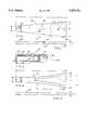
- FIG. 1is a working-side plan view of a micro-flexure structure (this figure being employed to depict three modifications) constructed in accordance with the present invention - such structure being intended for magnetic read/write applications, and thus including integrated read/write head and related electrical structure.
- FIG. 2is a side elevation taken from the upper side of FIG. 1.
- FIG. 3is an enlarged, longitudinal, lateral cross section of a fragment of the structure of FIGS. 1 and 2, illustrating integration therein of a probe-type head, and of an electrical coil and conductive traces connecting therewith, all of the latter being formed within the embedding, elongate, dielectric flexure body of the microflexure structure.
- FIG. 4is a working-side plan view of an alternative, curvilinearly configured embodiment of a micro-flexure structure (two more modifications being depicted here) constructed in accordance with the present invention.
- FIG. 5is a side elevation taken from the upper side of FIG. 4.
- FIGS. 1-3, inclusiveindicated generally at 20 is a micro-flexure structure, herein illustrated as a read/write head/flexure/conductor structure, which is constructed in accordance with the present invention.
- Structure 20 in this, and in all other embodiments disclosed herein,has an overall mass which is less than about 3.0-milligrams.
- FIG. 1is employed herein to illustrate, alternatively, three different modifications of one outline-type (rectilinear) embodiment of the invention.
- the fragmentary dash-triple-dot linesindicate a generally orthogonal rectilinear micro-flexure structure like the structure which is illustrated in the above-reference patent applications.
- the solid lines in this figureillustrate a solid-body, tapered modification. And, the fragmentary region shown in dash-double-dot lines is to be read, as will be explained shortly, to illustrate a tapered modification with a through-the-body void space.
- Structure 20in the form now being described as being illustrative, has an overall cantilever length A of about 10.2-millimeters, a width B, adjacent mounting end 20b, of about 1.0-millimeters, a width C, adjacent free end 20c, of about 0.5-millimeters, and a thickness D, throughout most of its length, of about 40-micrometers.
- the micro-flexure read/write structure now being describedis formed with a probe-type head for perpendicular recording, with this head including a main pole 22, a yoke 24, a back-gap stud 26, and a flux-return yoke 28.
- These componentsreferred to collectively as read/write pole structure, are magnetically coupled to form a low-reluctance path, terminating in a high-reluctance gap 30 between main pole 22 and the end of flux-return yoke 28.
- a probe-type headbe incorporated in the structure 20. More specifically, and as is plainly expressed in material elaborated in the referenced prior-filed applications, other kinds of read/write heads for specific use in conjunction with other-than-perpendicular kinds of recording may readily be used.
- Other types of magnetic head structurescould be employed, such as cross-field structures, like what is disclosed in U.S. Pat. No. 4,751,598, and magneto-resistive structures, such as disclosed in U.S. Pat. No. 4,878,140.
- inductively coupled to yoke 24 in structure 20is electrical structure including an electrically conductive helix coil 32, the ends of which coil connect through lead conductors, such as conductor 34, to suitable connective bonding pads (not shown) formed adjacent the mounting end of structure 20.
- the magnetic read/write pole structure, and the electrical coil and conductor structure (means), just generally described,are formed preferably in the manner set forth in detail in the referenced prior-application material as structure embedded within an elongate, dielectric flexure body which is made herein of a suitable metal oxide, such as, for example, aluminum oxide.
- a suitable metal oxidesuch as, for example, aluminum oxide.
- recognized, usable flexure-body materialsinclude silicon dioxide, diamond-like carbon, as well as others.
- the modification suggested by dash-double-dot lines which appear on flexure body 36 in FIG. 1is one wherein this body is formed with a through-the-body void space which both lightens the mass of the overall structure, and offers some slightly different mechanical dynamic/spring/resonance, etc., characteristics.
- a fragment of such a void spaceis shown generally at 38, and this fragment (were it fully shown in FIG. 1) represents a void space that has generally the same kind of appearance as the void space which appears in nearly complete solid-perimetraloutline form in the structural embodiment illustrated in FIG. 4. Referring to, and thus borrowing, letter designators for void-space dimensions that appear in FIG.
- space 38has a lateral dimension H, adjacent the mounting end of structure 20, of about 0.5-millimeters, a lateral width I, located toward its terminus roughly midway between opposite ends of structure 20, of about 0.13-millimeters, and an overall length G of about 7.6-millimeters.
- a trapezoidal flexure beam having a free-end width equal to the width of rectangular beamhas a dramatically increased lateral resonant frequency, a slightly increased vertical resonant frequency, and a moderately decreased torsional resonant frequency.
- the higher flexure structure masscan be tolerated so long as the "effective mass" of the head and flexure combination is less than about 1.5-milligrams, beyond which point it is believed that the effective mass or inertia of the head/flexure combination would create an unacceptable risk of catastrophic wear when the head operated in contact with a high speed rotating rigid disk.
- the "effective mass" of a head and flexure combinationis the equivalent free mass that would accelerate at the same rate as the head structure when subjected to a given net inertial force in a direction perpendicular to the disk surface.
- the resultant acceleration of the headis determined not only by the actual mass of the head structure, but also by the mass of a portion of the flexure beam, which necessarily moves along with the head.
- the effective mass of typical head/flexure combinationscan be approximated by adding one-fourth to one-third of the mass of the flexure structure to the mass of the head structure, and in present air-bearing "micro-slider" heads (also referred to as "seventy-percent slider”), the effective mass is about 26.5-milligrams.
- the effective mass of the head/flexure combination employed in a preferred embodiment of the present inventionis only about 1.0-milligrams (1/3 ⁇ 3-milligrams mass for the trapezoidal flexure beam--in this embodiment, the head structure adds only trivial mass contributions), which is below the threshold at which the risk of catastrophic wear or head crash arising from head/disk contact becomes a significant limiting factor on component reliability.
- head/flexure components having higher resonant frequenciespermit the servo electronics to be designed utilizing a higher bandwidth, which allows faster and more accurate positioning.
- the higher bandwidth servoprovides a stiffer servo response, which allows a disk drive utilizing such a servo to respond faster to externally applied disturbances, such as shock and vibration.
- the increased accuracy of the high bandwidth servo, coupled with the stiff mechanical componentspermits higher track densities to be achieved.
- the trapezoidal flexure structuremay employ a void space in order to control the vertical stiffness of the flexure without compromising the lateral stiffness. The void space would also reduce the effective mass of the head/flexure structure.
- the vertical stiffness of the flexuremust be carefully controlled because if the vertical stiffness is too high, the head/flexure structure will be overly sensitive to small changes in the height of the disk surface. Conversely, a low vertical stiffness may provide an insufficient force to maintain a uniform contact between the head and disk during operation.
- FIGS. 4 and 5show at 40 an additional embodiment of a read/write head/flexure/conductor structure, with structure 40 being substantially the same in all respects (two modifications being illustrated by these figures) as what is shown in FIGS. 1-3, inclusive, with the exception that the tapering outline of the integrated flexure body, from its mounting end toward its free end, is characterized by curvilinearity, and more particularly, by the slight concave curvilinearity clearly apparent in FIG. 4.
- Solid lines in the center of structure 40illustrate a through-the-body void space--fragmented at one end (the right end) to illustrate a body structure without such a void space.
- a curvilinear designcan be fabricated which further optimizes the resonant, mechanical, and dynamic characteristics of a flexure beam.
- Computer aided design and simulation toolscan be used to provide curvilinear flexure beam shapes that optimize lateral resonance while minimizing increases in mass and vertical stiffness.
- Designscan include optimized solid curvilinear flexure beams, as well as curvilinear beams having void spaces as shown in FIG. 4. Due to the novel flexure beam fabrication technique disclosed herein, these shapes can be made with a minimum increase in manufacturing complexity over rectangular and trapezoidal shapes.
- All of the embodiments of the micro-flexure structure of the inventionare formed utilizing a unique methodology wherein a metal oxide is patterned using thin film techniques and deposited on a suitable substrate structure to have a predefined general outline and topography.
- the substrateis prepared preferably with an etchable layer, and in certain instances, with a pair of commonly etchable lateral-dimension-boundary-defining walls/stripes which can be removed selectively by an ablation process, such as laser or chemical etching, or reactive-ion etching, or a combination thereof, to effect final lateral side definition for a unit, and to free the unit from the substrate.
- an ablation processsuch as laser or chemical etching, or reactive-ion etching, or a combination thereof.
- micro-flexure structure of the inventioncan be formed utilizing a commonly, chemically etchable substrate coating, or layer, and a pattern of walls/stripes that define the lateral topographical outlines of the various structures.
- etch-type processescan be used effectively to define the topographic outlines of structures like those described, and a pair of such additional techniques are now discussed.
- a laser approach to precision formation of microflexure body structuresinvolves preparation on a host substrate, through deposition and patterning steps like those expressed in the referenced patent applications, of what might be thought of as a generally continuous layer of dielectric flexure body-forming material, such as the several materials mentioned hereinabove, with appropriate read/write pole, etc. structures formed in an integrated fashion within this material and distributed throughout over the substrate at predetermined locations.
- a focused laser beam of high power densityfor example in the range of about 10 2 to about 10 6 watts/cm 2
- short pulse durationon the order of nanoseconds
- the requisite laser operating parameters, and the relative motion of the beam and of the deposit-carrying host substrate (the workpiece),are computer controlled.
- the output from the Nd:YAG or Nd:Glass lasermay be frequency doubled, tripled or quadrupled to obtain the required output from the visible to the ultraviolet region of the electromagnetic spectrum, if necessary.
- the beam spot sizeis controlled by an automated aperture.
- a mask stencilmay be used to define the desired pattern shape, recognizing that this latter method may require additional deposition steps.
- the ability of a laser beam thus to etch and ablate deposited material to form micro-flexure structures according to this inventiondepends upon the coupling which exists between the light and the material to be etched (i.e. optimum laser operating parameters may vary depending upon the absorptive capacity of the to-be-etched material). Frequencies in the ultraviolet range appear to be the most effective for defining accurate etch activity in aluminum oxide films of the thickness contemplated.
- a computer-controlled laser etch processcan be used effectively to define the shapes, boundaries, etc. of integrated, unitary head/flexure/conductor structures, and the like. Because of the fact that relative movement of the laser beam spot can be predictably repeatable and precisely guided under computer control, economical fabrication of small structures, having a wide variety of pre-selected shapes optimized for different ultimate operating environments, can easily be accomplished.
- an anisotropic etch, ablation processsuch as a reactive-ion (plasma)-etch-through-a-mask process, can be used as an alternative to either a chemical etch or a laser etch process. Because such a reactive plasma etch process is largely anisotropic, the lateral side wall definitions of individual etched components can be quite precise and uniform.
- a reactive-ion (plasma)-etch-through-a-mask processcan be used as an alternative to either a chemical etch or a laser etch process. Because such a reactive plasma etch process is largely anisotropic, the lateral side wall definitions of individual etched components can be quite precise and uniform.
- a microflexure structureand an ablation/etching methodology of making the same, which offer a very high degree of precision, infinitely variable control over the topology, and therefore the various performance characteristics, of a micro-flexure structure.
Landscapes
- Engineering & Computer Science (AREA)
- Manufacturing & Machinery (AREA)
- Supporting Of Heads In Record-Carrier Devices (AREA)
Abstract
Description
Claims (34)
Priority Applications (1)
| Application Number | Priority Date | Filing Date | Title |
|---|---|---|---|
| US07/992,886US5453315A (en) | 1989-11-27 | 1992-12-14 | Unitary micro-flexure structure and method of making same |
Applications Claiming Priority (4)
| Application Number | Priority Date | Filing Date | Title |
|---|---|---|---|
| US07/441,716US5041932A (en) | 1989-11-27 | 1989-11-27 | Integrated magnetic read/write head/flexure/conductor structure |
| US74691691A | 1991-08-19 | 1991-08-19 | |
| US91168092A | 1992-07-08 | 1992-07-08 | |
| US07/992,886US5453315A (en) | 1989-11-27 | 1992-12-14 | Unitary micro-flexure structure and method of making same |
Related Parent Applications (2)
| Application Number | Title | Priority Date | Filing Date |
|---|---|---|---|
| US74691691AContinuation-In-Part | 1989-11-27 | 1991-08-19 | |
| US91168092AContinuation-In-Part | 1989-11-27 | 1992-07-08 |
Publications (1)
| Publication Number | Publication Date |
|---|---|
| US5453315Atrue US5453315A (en) | 1995-09-26 |
Family
ID=27412099
Family Applications (1)
| Application Number | Title | Priority Date | Filing Date |
|---|---|---|---|
| US07/992,886Expired - LifetimeUS5453315A (en) | 1989-11-27 | 1992-12-14 | Unitary micro-flexure structure and method of making same |
Country Status (1)
| Country | Link |
|---|---|
| US (1) | US5453315A (en) |
Cited By (21)
| Publication number | Priority date | Publication date | Assignee | Title |
|---|---|---|---|---|
| US5593606A (en)* | 1994-07-18 | 1997-01-14 | Electro Scientific Industries, Inc. | Ultraviolet laser system and method for forming vias in multi-layered targets |
| US5632669A (en)* | 1995-05-26 | 1997-05-27 | Censtor Corporation | Interactive method for lapping transducers |
| US5701218A (en)* | 1996-07-03 | 1997-12-23 | Seagate Technology, Inc. | Flex on suspension design minimizing sensitivities to environmental stresses |
| US5942871A (en)* | 1994-04-01 | 1999-08-24 | Nikon Corporation | Double flexure support for stage drive coil |
| US6002550A (en)* | 1992-01-20 | 1999-12-14 | Fujitsu, Ltd. | Magnetic head assembly with ball member for electrically connecting the slider member and the suspension member |
| US6163953A (en)* | 1995-10-27 | 2000-12-26 | Tdk Corporation | Manufacturing method of a suspension |
| US6212042B1 (en) | 1997-06-27 | 2001-04-03 | Seagate Technology Llc | Slider having air bearing surface which includes pads for disk storage system |
| US6316901B2 (en) | 1995-04-04 | 2001-11-13 | Nikon Corporation | Exposure apparatus and method utilizing isolated reaction frame |
| US6341415B2 (en) | 1992-08-31 | 2002-01-29 | Fujitsu Limited | Method for assembling a magnetic head assembly and magnetic disk drive using bonding balls connecting magnetic head terminals to wiring terminals |
| US6373662B1 (en) | 1990-11-09 | 2002-04-16 | Hutchinson Technology Incorporated | Partially etched flexure arms in an integrated gimbal suspension |
| US20020057535A1 (en)* | 2000-09-19 | 2002-05-16 | Takehiro Kamigama | Head arm assembly, disk apparatus with head arm assembly and manufacturing method of head arm assembly |
| US6421207B1 (en)* | 1995-12-28 | 2002-07-16 | Nec Corporation | Contact type magnetic disk drive |
| US6536265B1 (en) | 1999-12-02 | 2003-03-25 | Seagate Technology Llc | Micro-textured glide sliders for super-smooth media |
| US6603639B1 (en) | 1998-07-21 | 2003-08-05 | Seagate Technology Llc | Slider for disc storage system |
| US6735049B1 (en) | 2002-03-28 | 2004-05-11 | Mark A. Lauer | Electromagnetic heads, flexures and gimbals formed on and from a wafer substrate |
| US6809899B1 (en) | 2001-08-20 | 2004-10-26 | Western Digital (Fremont), Inc. | Magnetic heads for perpendicular recording with trapezoidal pole tips |
| US20050002009A1 (en)* | 1994-04-01 | 2005-01-06 | Nikon Corporation | Positioning device having dynamically isolated frame, and lithographic device provided with such a positioning device |
| US20050141132A1 (en)* | 2003-12-31 | 2005-06-30 | Wayne Soderfelt | Data storage device with dampers |
| US20060117730A1 (en)* | 2000-09-05 | 2006-06-08 | Donaldson Company, Inc. | Polymer, polymer microfiber, polymer nanofiber and applications including filter structures |
| US7365513B1 (en) | 1994-04-01 | 2008-04-29 | Nikon Corporation | Positioning device having dynamically isolated frame, and lithographic device provided with such a positioning device |
| US7916427B1 (en)* | 2000-07-21 | 2011-03-29 | Lauer Mark A | Electromagnetic heads, flexures, gimbals and actuators formed on and from a wafer substrate |
Citations (19)
| Publication number | Priority date | Publication date | Assignee | Title |
|---|---|---|---|---|
| US4517616A (en)* | 1982-04-12 | 1985-05-14 | Memorex Corporation | Thin film magnetic recording transducer having embedded pole piece design |
| US4558385A (en)* | 1981-01-09 | 1985-12-10 | Matsushita Electric Industrial Co., Ltd. | Thin film magnetic head |
| US4703383A (en)* | 1984-10-05 | 1987-10-27 | Fuji Photo Film Co., Ltd. | Coil conductor structure in thin-film magnetic head |
| US4734802A (en)* | 1984-10-02 | 1988-03-29 | Hitachi, Ltd. | Film magnetic head slider having a contacting portion containing zirconia and carbon |
| US4739431A (en)* | 1984-10-22 | 1988-04-19 | Sharp Kabushiki Kaisha | Thin-film magnetic head |
| US4809103A (en)* | 1984-02-03 | 1989-02-28 | Commissariat A L'energie Atomique | Head slider with an integrated flat magnetic head |
| US4819091A (en)* | 1987-04-30 | 1989-04-04 | International Business Machines Corporation | High speed magnetic disk contact recording system |
| US4855854A (en)* | 1987-02-09 | 1989-08-08 | Sumitomo Special Metal Co., Ltd. | Thin-film magnetic head |
| US4860139A (en)* | 1987-06-19 | 1989-08-22 | Censtor Corporation | Planarized read/write head and method |
| US4876790A (en)* | 1983-11-11 | 1989-10-31 | Budapesti Radiotechnikai Gyar | Magnetic information recording and/or reading head with increased wear-resistant properties and a method for manufacturing the same |
| US4897747A (en)* | 1987-03-06 | 1990-01-30 | Thomson-Csf | Write/read head including monocrystalline magnetic thin films protected by a coating having hardened and lubricating zones |
| US4943882A (en)* | 1987-02-09 | 1990-07-24 | Toshiaki Wada | Thin-film, perpendicular magnetic recording and reproducing head |
| US4949207A (en)* | 1986-09-17 | 1990-08-14 | Commissariat A L'energie Atomique | Planar structure thin film magnetic head |
| US5041932A (en)* | 1989-11-27 | 1991-08-20 | Censtor Corp. | Integrated magnetic read/write head/flexure/conductor structure |
| US5065271A (en)* | 1989-02-28 | 1991-11-12 | Mitsubishi Denki Kabushiki Kaisha | Thin film magnetic head apparatus and method of manufacturing the same |
| US5073242A (en)* | 1989-11-27 | 1991-12-17 | Censtor Corp. | Method of making integrated magnetic read/write head/flexure/conductor structure |
| US5111351A (en)* | 1989-11-27 | 1992-05-05 | Censtor Corp. | Integrated magnetic read/write head/flexure/conductor structure |
| US5126903A (en)* | 1989-05-03 | 1992-06-30 | Tdk Corporation | Combination of a magnetic head and a magnetic head supporting device |
| US5174012A (en)* | 1989-11-27 | 1992-12-29 | Censtor Corp. | Method of making magnetic read/write head/flexure/conductor unit(s) |
- 1992
- 1992-12-14USUS07/992,886patent/US5453315A/ennot_activeExpired - Lifetime
Patent Citations (20)
| Publication number | Priority date | Publication date | Assignee | Title |
|---|---|---|---|---|
| US4558385A (en)* | 1981-01-09 | 1985-12-10 | Matsushita Electric Industrial Co., Ltd. | Thin film magnetic head |
| US4517616A (en)* | 1982-04-12 | 1985-05-14 | Memorex Corporation | Thin film magnetic recording transducer having embedded pole piece design |
| US4876790A (en)* | 1983-11-11 | 1989-10-31 | Budapesti Radiotechnikai Gyar | Magnetic information recording and/or reading head with increased wear-resistant properties and a method for manufacturing the same |
| US4809103A (en)* | 1984-02-03 | 1989-02-28 | Commissariat A L'energie Atomique | Head slider with an integrated flat magnetic head |
| US4734802A (en)* | 1984-10-02 | 1988-03-29 | Hitachi, Ltd. | Film magnetic head slider having a contacting portion containing zirconia and carbon |
| US4703383A (en)* | 1984-10-05 | 1987-10-27 | Fuji Photo Film Co., Ltd. | Coil conductor structure in thin-film magnetic head |
| US4739431A (en)* | 1984-10-22 | 1988-04-19 | Sharp Kabushiki Kaisha | Thin-film magnetic head |
| US4949207A (en)* | 1986-09-17 | 1990-08-14 | Commissariat A L'energie Atomique | Planar structure thin film magnetic head |
| US4855854A (en)* | 1987-02-09 | 1989-08-08 | Sumitomo Special Metal Co., Ltd. | Thin-film magnetic head |
| US4943882A (en)* | 1987-02-09 | 1990-07-24 | Toshiaki Wada | Thin-film, perpendicular magnetic recording and reproducing head |
| US4897747A (en)* | 1987-03-06 | 1990-01-30 | Thomson-Csf | Write/read head including monocrystalline magnetic thin films protected by a coating having hardened and lubricating zones |
| US4819091A (en)* | 1987-04-30 | 1989-04-04 | International Business Machines Corporation | High speed magnetic disk contact recording system |
| US4860139A (en)* | 1987-06-19 | 1989-08-22 | Censtor Corporation | Planarized read/write head and method |
| US5065271A (en)* | 1989-02-28 | 1991-11-12 | Mitsubishi Denki Kabushiki Kaisha | Thin film magnetic head apparatus and method of manufacturing the same |
| US5126903A (en)* | 1989-05-03 | 1992-06-30 | Tdk Corporation | Combination of a magnetic head and a magnetic head supporting device |
| US5041932A (en)* | 1989-11-27 | 1991-08-20 | Censtor Corp. | Integrated magnetic read/write head/flexure/conductor structure |
| US5073242A (en)* | 1989-11-27 | 1991-12-17 | Censtor Corp. | Method of making integrated magnetic read/write head/flexure/conductor structure |
| US5111351A (en)* | 1989-11-27 | 1992-05-05 | Censtor Corp. | Integrated magnetic read/write head/flexure/conductor structure |
| US5163218A (en)* | 1989-11-27 | 1992-11-17 | Censtor Corp. | Method of making integrated magnetic read/write head/flexure/conductor structure |
| US5174012A (en)* | 1989-11-27 | 1992-12-29 | Censtor Corp. | Method of making magnetic read/write head/flexure/conductor unit(s) |
Non-Patent Citations (8)
| Title |
|---|
| "A New Thin Film Head Generation IC Head," Lazzari, IEEE Transaction on Magnetics, vol. 25, No. 5, Sep. 1989, p. 3190. |
| "A Single Pole Type Thin Film Head With a Narrower Gap Length," Murata, Journal of The Magnetics Society of Japan, vol. 13, Supplement, No. S1, 1989, p. 517. |
| "An Active Slider for Practical Contact Recording," Yeack-Scranton, IEEE Transactions on Magnetics, vol. 26, No. 5, Sep. 1990, p. 2478. |
| "The High Speed Flexible Disk Using a Micro-Head," Yasuda, IEEE Translation Journal on Magnetics in Japan, vol. 3, No. 8, Aug. 1988, p. 624. |
| A New Thin Film Head Generation IC Head, Lazzari, IEEE Transaction on Magnetics, vol. 25, No. 5, Sep. 1989, p. 3190.* |
| A Single Pole Type Thin Film Head With a Narrower Gap Length, Murata, Journal of The Magnetics Society of Japan, vol. 13, Supplement, No. S1, 1989, p. 517.* |
| An Active Slider for Practical Contact Recording, Yeack Scranton, IEEE Transactions on Magnetics, vol. 26, No. 5, Sep. 1990, p. 2478.* |
| The High Speed Flexible Disk Using a Micro Head, Yasuda, IEEE Translation Journal on Magnetics in Japan, vol. 3, No. 8, Aug. 1988, p. 624.* |
Cited By (37)
| Publication number | Priority date | Publication date | Assignee | Title |
|---|---|---|---|---|
| US6373662B1 (en) | 1990-11-09 | 2002-04-16 | Hutchinson Technology Incorporated | Partially etched flexure arms in an integrated gimbal suspension |
| US6002550A (en)* | 1992-01-20 | 1999-12-14 | Fujitsu, Ltd. | Magnetic head assembly with ball member for electrically connecting the slider member and the suspension member |
| US6141182A (en)* | 1992-01-20 | 2000-10-31 | Fujitsu Limited | Magnetic head assembly with contact-type head chip mounting and electrically connecting arrangements |
| US6341415B2 (en) | 1992-08-31 | 2002-01-29 | Fujitsu Limited | Method for assembling a magnetic head assembly and magnetic disk drive using bonding balls connecting magnetic head terminals to wiring terminals |
| US6049186A (en)* | 1994-04-01 | 2000-04-11 | Nikon Corporation | Method for making and operating an exposure apparatus having a reaction frame |
| US5942871A (en)* | 1994-04-01 | 1999-08-24 | Nikon Corporation | Double flexure support for stage drive coil |
| US20050002009A1 (en)* | 1994-04-01 | 2005-01-06 | Nikon Corporation | Positioning device having dynamically isolated frame, and lithographic device provided with such a positioning device |
| US6927840B2 (en) | 1994-04-01 | 2005-08-09 | Nikon Corporation | Positioning device having dynamically isolated frame, and lithographic device provided with such a positioning device |
| US6989647B1 (en) | 1994-04-01 | 2006-01-24 | Nikon Corporation | Positioning device having dynamically isolated frame, and lithographic device provided with such a positioning device |
| US7365513B1 (en) | 1994-04-01 | 2008-04-29 | Nikon Corporation | Positioning device having dynamically isolated frame, and lithographic device provided with such a positioning device |
| US6271640B1 (en) | 1994-04-01 | 2001-08-07 | Nikon Corporation | Exposure apparatus having reaction frame |
| US6281654B1 (en) | 1994-04-01 | 2001-08-28 | Nikon Corporation | Method for making apparatus with dynamic support structure isolation and exposure method |
| US6841965B2 (en) | 1994-04-01 | 2005-01-11 | Nikon Corporation | Guideless stage with isolated reaction stage |
| US5593606A (en)* | 1994-07-18 | 1997-01-14 | Electro Scientific Industries, Inc. | Ultraviolet laser system and method for forming vias in multi-layered targets |
| US6316901B2 (en) | 1995-04-04 | 2001-11-13 | Nikon Corporation | Exposure apparatus and method utilizing isolated reaction frame |
| US6683433B2 (en) | 1995-04-04 | 2004-01-27 | Nikon Corporation | Exposure apparatus and method utilizing isolated reaction frame |
| US20040095085A1 (en)* | 1995-04-04 | 2004-05-20 | Nikon Corporation | Window frame-guided stage mechanism |
| US6747732B1 (en) | 1995-04-04 | 2004-06-08 | Nikon Corporation | Method of making exposure apparatus with dynamically isolated reaction frame |
| US5632669A (en)* | 1995-05-26 | 1997-05-27 | Censtor Corporation | Interactive method for lapping transducers |
| US6163953A (en)* | 1995-10-27 | 2000-12-26 | Tdk Corporation | Manufacturing method of a suspension |
| US6421207B1 (en)* | 1995-12-28 | 2002-07-16 | Nec Corporation | Contact type magnetic disk drive |
| US5796556A (en)* | 1996-07-03 | 1998-08-18 | Seagate Technology, Inc. | Flex on suspension design minimizing sensitivities to environmental stresses |
| US5701218A (en)* | 1996-07-03 | 1997-12-23 | Seagate Technology, Inc. | Flex on suspension design minimizing sensitivities to environmental stresses |
| US6212042B1 (en) | 1997-06-27 | 2001-04-03 | Seagate Technology Llc | Slider having air bearing surface which includes pads for disk storage system |
| US6603639B1 (en) | 1998-07-21 | 2003-08-05 | Seagate Technology Llc | Slider for disc storage system |
| US7617588B1 (en) | 1999-11-09 | 2009-11-17 | Lauer Mark A | Method for making a device |
| US6536265B1 (en) | 1999-12-02 | 2003-03-25 | Seagate Technology Llc | Micro-textured glide sliders for super-smooth media |
| US7916427B1 (en)* | 2000-07-21 | 2011-03-29 | Lauer Mark A | Electromagnetic heads, flexures, gimbals and actuators formed on and from a wafer substrate |
| US20110176242A1 (en)* | 2000-07-21 | 2011-07-21 | Lauer Mark A | Electromagnetic Heads, Flexures, Gimbals And Actuators Formed On And From A Wafer Substrate |
| US8111487B2 (en)* | 2000-07-21 | 2012-02-07 | Lauer Mark A | Electromagnetic heads, flexures, gimbals and actuators formed on and from a wafer substrate |
| US8432643B1 (en) | 2000-07-21 | 2013-04-30 | Mark A. Lauer | Electromagnetic heads, flexures, gimbals and actuators formed on and from a wafer substrate |
| US20060117730A1 (en)* | 2000-09-05 | 2006-06-08 | Donaldson Company, Inc. | Polymer, polymer microfiber, polymer nanofiber and applications including filter structures |
| US6680824B2 (en)* | 2000-09-19 | 2004-01-20 | Tdk Corporation | Head arm assembly, disk apparatus with head arm assembly and manufacturing method of head arm assembly |
| US20020057535A1 (en)* | 2000-09-19 | 2002-05-16 | Takehiro Kamigama | Head arm assembly, disk apparatus with head arm assembly and manufacturing method of head arm assembly |
| US6809899B1 (en) | 2001-08-20 | 2004-10-26 | Western Digital (Fremont), Inc. | Magnetic heads for perpendicular recording with trapezoidal pole tips |
| US6735049B1 (en) | 2002-03-28 | 2004-05-11 | Mark A. Lauer | Electromagnetic heads, flexures and gimbals formed on and from a wafer substrate |
| US20050141132A1 (en)* | 2003-12-31 | 2005-06-30 | Wayne Soderfelt | Data storage device with dampers |
Similar Documents
| Publication | Publication Date | Title |
|---|---|---|
| US5453315A (en) | Unitary micro-flexure structure and method of making same | |
| EP0458444B1 (en) | Air bearing disk head slider | |
| EP0558202A1 (en) | Magnetic head slider fabrication | |
| US5894655A (en) | Monocoque head suspension and its method of construction | |
| US6178064B1 (en) | Air bearing slider with shaped taper | |
| US6381104B1 (en) | Write/read head supporting mechanism, and write/read system | |
| US5737826A (en) | Method of making a thin-film transducer design for undershoot reduction | |
| US7023663B2 (en) | Method and apparatus for improved attachment of a micro-actuator to a slider device | |
| US7185440B2 (en) | Sensing contact probe | |
| US5815346A (en) | Textured slider surface | |
| JPS59132416A (en) | Magnetic head slider assembly | |
| US4921508A (en) | Method of manufacturing magnetic head | |
| US6556380B2 (en) | Silicon sliders with trapezoidal shape and drie process for fabrication | |
| US5718036A (en) | Method for manufacturing a magnetic head | |
| US5483025A (en) | Unitary micro-flexure structure | |
| JP2961667B2 (en) | Method of manufacturing write and / or read head for magnetic recording | |
| JP2002133813A (en) | Suspension for disk drive | |
| EP0601852B1 (en) | An information recording and reproducing apparatus and a method for manufacturing a slider used in the same | |
| US5476131A (en) | Unitary micro-flexure structure and method of making same | |
| US6784398B2 (en) | Apparatus for controlling twist curvature of a disc head slider | |
| JP3736656B2 (en) | Surface acoustic wave actuator | |
| KR100474028B1 (en) | Magnetic head, method for producing same, and magnetic recording and/or reproducing system | |
| KR19980079805A (en) | Magnetic head and its manufacturing method | |
| US7149060B2 (en) | Actuation device and method for high density hard disk drive head | |
| US6181518B1 (en) | Transverse pressurization contour slider |
Legal Events
| Date | Code | Title | Description |
|---|---|---|---|
| AS | Assignment | Owner name:CENSTOR CORP., CALIFORNIA Free format text:ASSIGNMENT OF ASSIGNORS INTEREST.;ASSIGNORS:HAMILTON, HAROLD J.;MARTIN, TIMOTHY W.;REEL/FRAME:006491/0521 Effective date:19930225 | |
| AS | Assignment | Owner name:TL PARTNERS, OREGON Free format text:SECURITY INTEREST;ASSIGNOR:CENSTOR CORP.;REEL/FRAME:006732/0542 Effective date:19930924 Owner name:MMC/GATX PARTNERSHIP NO. I C/O GATX CAPITAL CORPOR Free format text:SECURITY INTEREST;ASSIGNOR:CENSTOR CORP.;REEL/FRAME:006732/0542 Effective date:19930924 Owner name:COMDISCO, INC., ILLINOIS Free format text:SECURITY INTEREST;ASSIGNOR:CENSTOR CORP.;REEL/FRAME:006732/0542 Effective date:19930924 | |
| AS | Assignment | Owner name:BRENTWOOD ASSOCIATES III, CALIFORNIA Free format text:SECURITY INTEREST;ASSIGNOR:CENSTOR CORP.;REEL/FRAME:006773/0062 Effective date:19931117 | |
| STCF | Information on status: patent grant | Free format text:PATENTED CASE | |
| AS | Assignment | Owner name:SILICON VALLEY BANK, CALIFORNIA Free format text:SECURITY INTEREST;ASSIGNOR:CENSTOR CORP;REEL/FRAME:007722/0019 Effective date:19951017 | |
| CC | Certificate of correction | ||
| AS | Assignment | Owner name:SILICON VALLEY BANK, CALIFORNIA Free format text:SECURITY INTEREST;ASSIGNOR:CENSTOR CORP.;REEL/FRAME:007846/0011 Effective date:19960131 | |
| AS | Assignment | Owner name:COLE, JAMES A. (AS COLLATERAL AGENT FOR THE ATTACH Free format text:SECURITY INTEREST;ASSIGNOR:CENSTOR CORPORATION;REEL/FRAME:008412/0001 Effective date:19960102 | |
| AS | Assignment | Owner name:CENSTOR CORP., CALIFORNIA Free format text:RELEASE OF SECURITY INTEREST;ASSIGNOR:HOWARD, RANDY;REEL/FRAME:008085/0102 Effective date:19960710 Owner name:CENSTOR CORP., CALIFORNIA Free format text:RELEASE OF SECURITY INTEREST;ASSIGNOR:J.P. MORGAN INVESTMENT CORP.;REEL/FRAME:008077/0855 Effective date:19960715 | |
| AS | Assignment | Owner name:CENSTOR CORP., CALIFORNIA Free format text:RELEASE OF SECURITY INTEREST WHICH WAS EXECUTED AS OF JULY 15, 1996.;ASSIGNORS:BRENTWOOD ASSOCIATES II LIQUIDATING TRUST;BRENTWOOD ASSOCIATES III LIQUIDATING TRUST;BRENTWOOD ASSOCIATES IV LIQUIDATING TRUST;AND OTHERS;REEL/FRAME:008113/0845 Effective date:19960715 Owner name:CENSTOR CORP., CALIFORNIA Free format text:RELEASE OF SECURITY INTEREST;ASSIGNOR:WOLFENSOHN ASSOCIATES L.P.;REEL/FRAME:008113/0285 Effective date:19960712 Owner name:CENSTOR CORP., CALIFORNIA Free format text:RELEASE BY SECURED PARTY;ASSIGNORS:MMC/GATX PARTNERSHIP NO. I;TL PARTNERS;COMDISCO, INC.;REEL/FRAME:008119/0097 Effective date:19960712 Owner name:CENSTOR CORP., CALIFORNIA Free format text:RELEASE OF SECURITY INTEREST;ASSIGNOR:SILICON VALLEY BANK OF SANTA CLARA, CALIFORNIA;REEL/FRAME:008119/0115 Effective date:19960716 Owner name:CENSTOR CORP., CALIFORNIA Free format text:RELEASE BY SECURED PARTY;ASSIGNORS:MORGENTHALER VENTURE PARTNERS;MORGENTHALER VENTURE PARTNERS II;REEL/FRAME:008119/0323 Effective date:19960715 | |
| AS | Assignment | Owner name:CENSTOR CORP., CALIFORNIA Free format text:ASSIGNMENT OF ASSIGNORS INTEREST;ASSIGNORS:COLE, JAMES A. (AS COLLATERAL AGENT FOR THE ATTACHED SECURED PARTIES);ADVANCED TECHNOLOGY VENTURES III;AENEAS VENTURE CORPORATION;AND OTHERS;REEL/FRAME:008447/0365 Effective date:19970418 | |
| FEPP | Fee payment procedure | Free format text:PAT HLDR NO LONGER CLAIMS SMALL ENT STAT AS SMALL BUSINESS (ORIGINAL EVENT CODE: LSM2); ENTITY STATUS OF PATENT OWNER: LARGE ENTITY | |
| FPAY | Fee payment | Year of fee payment:4 | |
| FPAY | Fee payment | Year of fee payment:8 | |
| FEPP | Fee payment procedure | Free format text:PAYOR NUMBER ASSIGNED (ORIGINAL EVENT CODE: ASPN); ENTITY STATUS OF PATENT OWNER: LARGE ENTITY | |
| AS | Assignment | Owner name:SEAGATE TECHNOLOGY LLC, CALIFORNIA Free format text:PATENT ASSIGNMENT AGREEMENT;ASSIGNOR:CENSTOR CORPORATION;REEL/FRAME:014289/0177 Effective date:20030711 | |
| FPAY | Fee payment | Year of fee payment:12 | |
| AS | Assignment | Owner name:WELLS FARGO BANK, NATIONAL ASSOCIATION, AS COLLATERAL AGENT AND SECOND PRIORITY REPRESENTATIVE, CALIFORNIA Free format text:SECURITY AGREEMENT;ASSIGNORS:MAXTOR CORPORATION;SEAGATE TECHNOLOGY LLC;SEAGATE TECHNOLOGY INTERNATIONAL;REEL/FRAME:022757/0017 Effective date:20090507 Owner name:JPMORGAN CHASE BANK, N.A., AS ADMINISTRATIVE AGENT AND FIRST PRIORITY REPRESENTATIVE, NEW YORK Free format text:SECURITY AGREEMENT;ASSIGNORS:MAXTOR CORPORATION;SEAGATE TECHNOLOGY LLC;SEAGATE TECHNOLOGY INTERNATIONAL;REEL/FRAME:022757/0017 Effective date:20090507 Owner name:JPMORGAN CHASE BANK, N.A., AS ADMINISTRATIVE AGENT Free format text:SECURITY AGREEMENT;ASSIGNORS:MAXTOR CORPORATION;SEAGATE TECHNOLOGY LLC;SEAGATE TECHNOLOGY INTERNATIONAL;REEL/FRAME:022757/0017 Effective date:20090507 Owner name:WELLS FARGO BANK, NATIONAL ASSOCIATION, AS COLLATE Free format text:SECURITY AGREEMENT;ASSIGNORS:MAXTOR CORPORATION;SEAGATE TECHNOLOGY LLC;SEAGATE TECHNOLOGY INTERNATIONAL;REEL/FRAME:022757/0017 Effective date:20090507 | |
| AS | Assignment | Owner name:SEAGATE TECHNOLOGY INTERNATIONAL, CALIFORNIA Free format text:RELEASE;ASSIGNOR:JPMORGAN CHASE BANK, N.A., AS ADMINISTRATIVE AGENT;REEL/FRAME:025662/0001 Effective date:20110114 Owner name:MAXTOR CORPORATION, CALIFORNIA Free format text:RELEASE;ASSIGNOR:JPMORGAN CHASE BANK, N.A., AS ADMINISTRATIVE AGENT;REEL/FRAME:025662/0001 Effective date:20110114 Owner name:SEAGATE TECHNOLOGY HDD HOLDINGS, CALIFORNIA Free format text:RELEASE;ASSIGNOR:JPMORGAN CHASE BANK, N.A., AS ADMINISTRATIVE AGENT;REEL/FRAME:025662/0001 Effective date:20110114 Owner name:SEAGATE TECHNOLOGY LLC, CALIFORNIA Free format text:RELEASE;ASSIGNOR:JPMORGAN CHASE BANK, N.A., AS ADMINISTRATIVE AGENT;REEL/FRAME:025662/0001 Effective date:20110114 | |
| AS | Assignment | Owner name:THE BANK OF NOVA SCOTIA, AS ADMINISTRATIVE AGENT, CANADA Free format text:SECURITY AGREEMENT;ASSIGNOR:SEAGATE TECHNOLOGY LLC;REEL/FRAME:026010/0350 Effective date:20110118 Owner name:THE BANK OF NOVA SCOTIA, AS ADMINISTRATIVE AGENT, Free format text:SECURITY AGREEMENT;ASSIGNOR:SEAGATE TECHNOLOGY LLC;REEL/FRAME:026010/0350 Effective date:20110118 | |
| AS | Assignment | Owner name:SEAGATE TECHNOLOGY INTERNATIONAL, CAYMAN ISLANDS Free format text:TERMINATION AND RELEASE OF SECURITY INTEREST IN PATENT RIGHTS;ASSIGNOR:WELLS FARGO BANK, NATIONAL ASSOCIATION, AS COLLATERAL AGENT AND SECOND PRIORITY REPRESENTATIVE;REEL/FRAME:030833/0001 Effective date:20130312 Owner name:EVAULT INC. (F/K/A I365 INC.), CALIFORNIA Free format text:TERMINATION AND RELEASE OF SECURITY INTEREST IN PATENT RIGHTS;ASSIGNOR:WELLS FARGO BANK, NATIONAL ASSOCIATION, AS COLLATERAL AGENT AND SECOND PRIORITY REPRESENTATIVE;REEL/FRAME:030833/0001 Effective date:20130312 Owner name:SEAGATE TECHNOLOGY LLC, CALIFORNIA Free format text:TERMINATION AND RELEASE OF SECURITY INTEREST IN PATENT RIGHTS;ASSIGNOR:WELLS FARGO BANK, NATIONAL ASSOCIATION, AS COLLATERAL AGENT AND SECOND PRIORITY REPRESENTATIVE;REEL/FRAME:030833/0001 Effective date:20130312 Owner name:SEAGATE TECHNOLOGY US HOLDINGS, INC., CALIFORNIA Free format text:TERMINATION AND RELEASE OF SECURITY INTEREST IN PATENT RIGHTS;ASSIGNOR:WELLS FARGO BANK, NATIONAL ASSOCIATION, AS COLLATERAL AGENT AND SECOND PRIORITY REPRESENTATIVE;REEL/FRAME:030833/0001 Effective date:20130312 | |
| AS | Assignment | Owner name:SEAGATE TECHNOLOGY PUBLIC LIMITED COMPANY, CALIFORNIA Free format text:RELEASE BY SECURED PARTY;ASSIGNOR:THE BANK OF NOVA SCOTIA;REEL/FRAME:072193/0001 Effective date:20250303 Owner name:SEAGATE TECHNOLOGY, CALIFORNIA Free format text:RELEASE BY SECURED PARTY;ASSIGNOR:THE BANK OF NOVA SCOTIA;REEL/FRAME:072193/0001 Effective date:20250303 Owner name:SEAGATE TECHNOLOGY HDD HOLDINGS, CALIFORNIA Free format text:RELEASE BY SECURED PARTY;ASSIGNOR:THE BANK OF NOVA SCOTIA;REEL/FRAME:072193/0001 Effective date:20250303 Owner name:I365 INC., CALIFORNIA Free format text:RELEASE BY SECURED PARTY;ASSIGNOR:THE BANK OF NOVA SCOTIA;REEL/FRAME:072193/0001 Effective date:20250303 Owner name:SEAGATE TECHNOLOGY LLC, CALIFORNIA Free format text:RELEASE BY SECURED PARTY;ASSIGNOR:THE BANK OF NOVA SCOTIA;REEL/FRAME:072193/0001 Effective date:20250303 Owner name:SEAGATE TECHNOLOGY INTERNATIONAL, CAYMAN ISLANDS Free format text:RELEASE BY SECURED PARTY;ASSIGNOR:THE BANK OF NOVA SCOTIA;REEL/FRAME:072193/0001 Effective date:20250303 Owner name:SEAGATE HDD CAYMAN, CAYMAN ISLANDS Free format text:RELEASE BY SECURED PARTY;ASSIGNOR:THE BANK OF NOVA SCOTIA;REEL/FRAME:072193/0001 Effective date:20250303 Owner name:SEAGATE TECHNOLOGY (US) HOLDINGS, INC., CALIFORNIA Free format text:RELEASE BY SECURED PARTY;ASSIGNOR:THE BANK OF NOVA SCOTIA;REEL/FRAME:072193/0001 Effective date:20250303 |