US5453098A - Two step IV fluid flow stop - Google Patents
Two step IV fluid flow stopDownload PDFInfo
- Publication number
- US5453098A US5453098AUS08/241,041US24104194AUS5453098AUS 5453098 AUS5453098 AUS 5453098AUS 24104194 AUS24104194 AUS 24104194AUS 5453098 AUS5453098 AUS 5453098A
- Authority
- US
- United States
- Prior art keywords
- tube
- slide clamp
- occluding
- locking
- aperture
- Prior art date
- Legal status (The legal status is an assumption and is not a legal conclusion. Google has not performed a legal analysis and makes no representation as to the accuracy of the status listed.)
- Expired - Lifetime
Links
Images


Classifications
- A—HUMAN NECESSITIES
- A61—MEDICAL OR VETERINARY SCIENCE; HYGIENE
- A61M—DEVICES FOR INTRODUCING MEDIA INTO, OR ONTO, THE BODY; DEVICES FOR TRANSDUCING BODY MEDIA OR FOR TAKING MEDIA FROM THE BODY; DEVICES FOR PRODUCING OR ENDING SLEEP OR STUPOR
- A61M39/00—Tubes, tube connectors, tube couplings, valves, access sites or the like, specially adapted for medical use
- A61M39/22—Valves or arrangement of valves
- A61M39/28—Clamping means for squeezing flexible tubes, e.g. roller clamps
- A61M39/286—Wedge clamps, e.g. roller clamps with inclined guides
- A61M39/287—Wedge formed by a slot having varying width, e.g. slide clamps
- A—HUMAN NECESSITIES
- A61—MEDICAL OR VETERINARY SCIENCE; HYGIENE
- A61M—DEVICES FOR INTRODUCING MEDIA INTO, OR ONTO, THE BODY; DEVICES FOR TRANSDUCING BODY MEDIA OR FOR TAKING MEDIA FROM THE BODY; DEVICES FOR PRODUCING OR ENDING SLEEP OR STUPOR
- A61M39/00—Tubes, tube connectors, tube couplings, valves, access sites or the like, specially adapted for medical use
- A61M39/22—Valves or arrangement of valves
- A61M39/28—Clamping means for squeezing flexible tubes, e.g. roller clamps
- A61M39/281—Automatic tube cut-off devices, e.g. squeezing tube on detection of air
- F—MECHANICAL ENGINEERING; LIGHTING; HEATING; WEAPONS; BLASTING
- F16—ENGINEERING ELEMENTS AND UNITS; GENERAL MEASURES FOR PRODUCING AND MAINTAINING EFFECTIVE FUNCTIONING OF MACHINES OR INSTALLATIONS; THERMAL INSULATION IN GENERAL
- F16L—PIPES; JOINTS OR FITTINGS FOR PIPES; SUPPORTS FOR PIPES, CABLES OR PROTECTIVE TUBING; MEANS FOR THERMAL INSULATION IN GENERAL
- F16L55/00—Devices or appurtenances for use in, or in connection with, pipes or pipe systems
- F16L55/10—Means for stopping flow in pipes or hoses
Definitions
- This inventionis in the field of intravenous (IV) infusion devices such as peristaltic pumps and the associated flexible IV tubing and other related devices. Specifically, this invention pertains to devices used to prevent free flow in an IV tube when the infusion pump is disengaged from the IV tube.
- IVintravenous
- a pumping devicesuch as a peristaltic pump.
- Such pumpsare useful because they can deliver the medication in a highly controlled fashion, and because they do so without coming in contact with the medication.
- the fluidis moved through a flexible IV tube by pressing a pumping member against the tube sufficiently to occlude the tube, and then moving the pumping member along the tube to advance the fluid which is trapped downstream of the occlusion.
- a second pumping memberrepeats the process by occluding the tube and moving a second captured quantity of fluid along behind the first.
- the distance between occlusions and the speed of movement of the pumping memberscan be precisely controlled to effectively control the rate of infusion of the fluid into the patient.
- the IV tubeis at all times occluded by one of the pumping members, thereby preventing "free flow" of fluid, by means other than the action of the pumping members.
- the peristaltic pumping mechanismIt is common for the peristaltic pumping mechanism to be housed in a housing with a hinged door.
- the tube through which the fluid is to be movedis placed in contact with the pumping mechanism inside the door, with the ends of the tubing typically extending out the top and bottom of the door opening.
- a platen on the inside of the doorpresses against the IV tube to provide a backing surface against which the pumping members can occlude the tube.
- the manual devicesrequire some manipulation skill on the part of the attending technician, and there is always the chance that the technician will forget to properly time the occlusion of the tube relative to the opening of the door on the pumping device. Furthermore, the door may be accidentally opened, resulting in free flow in the tube.
- the known automatic devices mounted on the infusion pumpare not uniformly reliable in timing the occlusion and release of the tube with the disengagement and engagement, respectively, of the pumping members.
- the action of opening the dooris relied on to initiate the occlusion of the IV tube
- the action of closing the dooris relied on to initiate the release of the IV tube. Therefore, at least momentary free flow of fluid can occur in some of these devices, or very accurate and repetitive alignment of the operative surfaces of the occlusion mechanism can be required.
- Some known devicesalso will allow the occluding device in the pump to be independently disengaged, whether by accident or on purpose, without the door being closed. This obviously results in the free flow of fluid.
- the object of the present inventionis to provide an apparatus which will automatically and positively occlude an IV tube before the pumping mechanism is disengaged from the tube.
- a further object of the present inventionis to provide an apparatus which will automatically and positively maintain the IV tube in an occluded state until after the pumping mechanism is engaged with the tube.
- a still further objectis to provide an apparatus which will reliably occlude the IV tube, which is inexpensive to manufacture and easy to use.
- the present inventionin its preferred embodiment, by way of example, consists of a base member to which the IV tube is stationarily attached, and a slide clamp which slides relative to the base member and relative to the IV tube.
- a tubular toweris mounted on the base member to provide an attachment point for the IV tube.
- the toweris mounted with its longitudinal axis perpendicular to the main body of the base member, and the tower is hollow and open at both ends.
- the open bottom end of the towerwhich is the end attached to the base member, is sized to receive the IV tube within, in a liquid tight, structurally secure fit. Attachment of the tube within the tower can be by an interference fit or compression fit, and the attachment can be facilitated by gluing or other types of bonding.
- the IV tubeexits the bottom of the tower and continues on toward the patient.
- a pumping tubeis attached to the top of the tower, and the pumping tube extends through the pump mechanism, such as a peristaltic pump.
- the slide clampis slidingly mounted to the main body of the base member, with the relative sliding motion being in a direction oblique or perpendicular to the longitudinal axis of the tower. Therefore, the sliding motion is also oblique or perpendicular to the axis of the IV tube.
- the tubepasses through an elongated aperture in the slide clamp, with the elongated dimension of the aperture being arranged parallel to the direction of the sliding motion.
- One end of the elongated apertureis a relatively open hole sized to receive the IV tube without constricting it, while the other end of the aperture is a relatively narrow slot sized to sufficiently constrict the IV tube to cause complete occlusion.
- the exact location of the tube within the apertureis determined by the position of the slide clamp relative to the base member.
- the slide clamphas two functional positions in this respect.
- An occluding positionis defined when the slide clamp is partially slidingly withdrawn from the base member.
- An open position of the slide clampis defined when the slide clamp does not fully occlude the tube.
- the slide clampis positioned in the full open position, the IV tube passes through the end of the aperture which has the relatively open hole.
- At least one flexible cantilevered locking armis formed on the base member, to interlock with a locking projection on the slide clamp.
- the locking armis formed to lie generally parallel to the main body of the base member, and generally parallel to the direction of the siding motion.
- the free cantilevered end of the locking armis biased toward the slide clamp.
- the slide clampWhen the slide clamp is moved to its occluding position, the free end of the locking arm snaps in behind the locking projection on the slide clamp as it slides past, causing the locking arm to interlock with the locking projection. This prevents the slide clamp from returning from the occluding position to the open position, until the locking arm is released from the locking projection.
- a release tabprojects from the locking arm to facilitate releasing the locking arm from the locking projection by pressing the tab toward the tower, thereby flexing the free end of the locking arm away from the slide clamp.
- the flow stopis installed in a pumping apparatus so as to interact with a door or other moving mechanism on the pumping apparatus to move the slide clamp from its open position to its occluding position, or vice versa.
- the doorcan have a boss or other feature positioned to contact the release tab as the door is shut, thereby releasing the locking arm from the locking projection.
- the doorcan also have a latching mechanism which is activated after the door is shut, to push the slide clamp into full engagement with the base member after the boss on the door has released the locking arm.
- the doorcan have a hook or other means to hook onto a second projection on the slide clamp, to pull the slide clamp partially out of engagement with the base member before the door is opened, thereby occluding the IV tube.
- This hookcan also be formed on the latching mechanism, so that as the latch is set, the slide clamp is moved to the open position, and as the latch is released, the slide clamp is moved to the occluding position. Both movements of the slide clamp are therefore achieved while the door is shut, and while the pumping mechanism is engaged with the pumping tube.
- the hook on the latchcontacts a projection on the slide clamp and pulls the slide clamp partially out of the base member, thereby occluding the IV tube. This prevents free flow of fluid in the IV tube when the door is subsequently opened and the pump is disabled.
- the boss on the doorpresses on the release tab, followed by the latch mechanism being engaged to push the slide clamp into engagement with the base member, thereby allowing the tube to open. This allows flow of fluid in the IV tube as the pump operates.
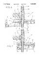
- FIG. 1is a perspective view of the flow stop of the present invention, showing the slide clamp fully withdrawn from the base;
- FIG. 2is a plan view of the top of the slide clamp shown in FIG. 1;
- FIG. 3is a section view of the slide clamp shown in FIG. 1, taken along the line 3--3;
- FIG. 4is a section view of the base shown in FIG. 1, taken along the line 4--4;
- FIG. 5is a section view of the base shown in FIG. 1, taken along the same line as FIG. 4, showing the release tab pressed against the tower;
- FIG. 6is a section view of the device shown in FIG. 1, showing the slide clamp locked in the occluding position;
- FIG. 7is a section view of the device shown in FIG. 1, with the slide clamp in the open position.
- the flow stop 10consists generally of a relatively open, box shaped base 12 and a mating slide clamp 14. Both parts can be formed by injection molding from various plastic materials.
- the solid rectangular body 15 of the slide clamp 14is shaped and sized to fit slidingly within the base 12.
- the base 12has a tower 16 formed on the top surface 25 of the base 12, with the tower 16 extending upwardly from the base 12, substantially perpendicular to the base 12.
- the top end 21 of the tower 16is formed as a male tube connector 18 over which a pumping tube can be attached.
- the pumping tubecan be attached by other means if desired.
- the open bottom end 23 of the tower 16is attached to the base 12, and it is formed as a female tube connector into which an IV tube can be attached.
- the IV tube and the pumping tubecan be the same tube if desired, simply passing through the tower.
- the body 15 of the slide clamp 14is penetrated from its top surface 17 to its bottom surface 19 by an elongated aperture 20.
- the elongated dimension of the aperture 20is arranged on the slide clamp 14 to be parallel to the direction of the relative sliding movement between the base 12 and the slide clamp 14.
- Two side edges of the body 15 of the slide clamp 14are fitted with rails 22 which lie parallel to the direction of the relative sliding movement.
- the rails 22fit in a sliding fashion up through two rail channels 27 in the top of the base 12 and over two frames 24 formed on the edge of the base 12. Alignment of the slide clamp 14 with the base 12 is accomplished by the fit of the rails 22 over the frames 24, and by the fit of the body 15 of the slide clamp 14 between the frames 24.
- Two flexible cantilevered locking arms 28are molded into the top of the base 12, with their distal free ends 26 biased downwardly below the top surface 25 of the base 12. Biasing of the free ends 26 downwardly is accomplished by molding the locking arms 28 in a downwardly sloped configuration, but the biasing could also be accomplished by the use of springs or other means.
- a release tab 32is formed on the locking arms 28, projecting upwardly from the locking arms 28 substantially parallel to the longitudinal axis of the tower 16. In the free state, when the locking arms 28 are sloped downwardly relative to the top surface 25 of the base 12, the release tab 32 is spaced away from the outer surface of the tower 16. The free ends 26 of the locking arms 28 can be flexed upwardly by pressing the release tab 32 toward the tower 16. Without departing from the spirit of the invention, one locking arm 28 can be used in place of the two shown, or each locking arm 28 can have a separate release tab 32.
- Two locking projections 30are molded on the top surface 17 of the body 15 of the slide clamp 14, with the projections 30 taking the form of ramps.
- the locking projections 30are transversely positioned on the slide clamp 14 to align with the free ends 26 of the locking arms 28 when the slide clamp 14 is inserted into the base 12.
- the locking projections 30are also longitudinally positioned to prevent the slide clamp 14 from being inserted into the base 12 far enough to move from its occluding position to its open position.
- the elongated aperture 20 through the slide clamp 14has an open end 34 shaped essentially as a round hole with a sufficiently large diameter to allow a selected IV tube to pass through the open end 34 without being occluded.
- the diameter of the open end 34is large enough to allow the IV tube to remain unrestricted.
- the other end of the aperture 20is a relatively narrow slot 36.
- the width of the slot 36is sufficiently small that a selected IV tube passing through the slot 36 would be completely occluded and would remain occluded against a foreseeable range of fluid pressures in the IV tube.
- the range of pressure against which the tube would remain occludedwould include at least the static head anticipated during normal use of the infusion apparatus.
- the locking projections 30project upwardly from the top surface 17 of the body 15 of the slide clamp 14, presenting a substantially vertical locking face 38 to engage the free ends 26 of the locking arms 28, when the slide clamp 14 is in its occluding position.
- One or more pulling projections 40project downwardly from the bottom surface 19 of the body 15.
- Each of the pulling projections 40presents a substantially vertical pulling face 42 which will interact with the latch on the door of the pump housing (not shown) to pull the slide clamp 14 partially out of engagement with the base 12 before the door is opened. Pulling the slide clamp 14 partially out of the base 12 moves the slide clamp 14 from its open position to its occluding position.
- the body 15 of the slide clamp 14also presents a substantially vertical pushing face 44 on one end, against which the door of the housing pushes to fully insert the slide clamp 14 into the base 12, after the door is closed. Pushing the slide clamp 14 into full insertion with the base 12 moves the slide clamp 14 from its occluding position to its open position.
- FIG. 4illustrates the downward slope of the locking arms 28 which is molded into the locking arms 28 to create the necessary downward bias to engage the free ends 26 of the locking arms 28 with the locking faces 38 on the locking projections 30.
- the separation between the release tab 32 and the side of the tower 16can also be seen, as it exists when the locking arms are unrestrained.
- FIG. 5shows the upwardly flexed position of the free ends 26 of the locking arms 28 which results from pressing the release tab 32 toward the tower 16. In this view, the release tab 32 is shown contacting the tower 16, but it should be understood that the free ends 26 can be flexed upwardly a sufficient amount to release the locking arms 28 from the locking projections 30, without actually causing the release tab 32 to contact the tower 16.
- FIGS. 6 and 7show in general how the flow stop 10 of the present invention interacts with the door of the pump housing.
- FIG. 6shows the slide clamp 14 in its occluding position relative to the base 12, with the slide clamp 14 partially withdrawn from the base 12 and the free ends 26 of the locking arms 28 engaging the locking projections 30 to hold the slide clamp 14 in its occluding position. This position of the slide clamp is achieved before the door is opened and maintained until after the door is closed.
- FIG. 7shows the slide clamp 14 in its open position, with the slide clamp 14 fully inserted within the base 12 and the free ends 26 of the locking arms 28 flexed upwardly a sufficient amount to clear the locking projections 30.
- a releasing boss Acan be formed on the door and positioned to contact the release tab 32 as the door is moved to the shut position, and to press the release tab 32 toward the tower 16.
- a pushing boss Bcan be formed on the latch mechanism and positioned to contact the pushing face 44 on the slide clamp 14 as the latch is engaged to push the slide clamp 14 from its occluding position to its open position,
- one or more pulling hooks Ccan be formed on the latch mechanism and positioned to contact the pulling projections 40 as the latch is disengaged to pull the slide clamp 14 from its open position to its occluding position.
- Element A of the doormoves generally to the right as seen in the Figures when the door is moved to the shut position.
- Elements B and C of the latch mechanismcan be made to move generally to the left as seen in the Figures when the latch is being disengaged, and to the right when the latch is being engaged, it being understood that other elements (not shown) of the latch mechanism perform the actual latching of the door in the shut position.
- pulling hooks Ccan rotate in the clockwise direction from the position shown, relative to the remainder of the latch mechanism, against a spring bias.
- the slide clamp 14is fully inserted into the base 12 until the open end 34 of the aperture 20 aligns with the longitudinal axis of the tower 16.
- the release tab 32is manually pressed toward the tower 16 as necessary to allow full insertion of the slide clamp.
- a pumping tube 46is selected for its appropriate size, flexibility, and durability.
- One end of the selected pumping tube 46is attached to the tube connector 18 at the top end 21 of the tower 16 by being fit over the tube connector 18.
- One end of a selected IV tube 48is threaded through the open end 34 of the aperture 20 and attached to the base 12 by being fit into the bottom end 23 of the tower 16.
- the slide clamp 14is then manually withdrawn from the base 12 to occlude the IV tube 48.
- the other end of the pumping tube 46is connected to a supply (not shown) of the chosen fluid to be pumped.
- the door of the pump housingis opened and the flow stop 10 is placed inside the door with the base 12 securely mounted to the pump housing and the free ends 26 of the locking arms 28 projecting outwardly from the pump housing.
- the pumping tube 46is placed in contact with the pumping mechanism, and the door is shut.
- FIG. 6shows the slide clamp 14 in its occluding position, with the release boss A about to contact the release tab 32 as the door is shut. As the door is completely shut, the releasing boss A presses the release tab 32 toward the tower 16, flexing the locking arms 28 upwardly.
- FIG. 7shows the slide clamp 14 in its open position, with the pulling hooks C having pivoted behind the pulling projections.
- the pumpcan then be operated in the conventional fashion to purge the IV tube 48 of air, and the IV tube 48 can be connected to a venous access site.
- the latching mechanismmust first be disengaged, which will move the elements B and C to the left, causing the pulling hooks C to contact the pulling projections 40 and pull the slide clamp 14 to the left, to its occluding position.
- the latching mechanismcan be constructed by known means so that only after this occlusion occurs will the door be unlatched. At this time, the door can be opened.
- the locking arms 28, having engaged the locking projections 30,maintain the slide clamp 14 in its occluding position, even if the slide clamp 14 is pushed toward the base 12 with considerable force.
- the latching mechanismcan also be constructed by known means so that when the door has been unlatched, the latching mechanism can not be moved back to its latched position until the door has been shut. Therefore, if the door is to be shut, the releasing boss A will press the release tab 32 toward the tower 16 to release the locking arms 28 from engagement with the locking projections 30, and the slide clamp 14 can be subsequently moved to the open position as explained before.
Landscapes
- Health & Medical Sciences (AREA)
- Engineering & Computer Science (AREA)
- Heart & Thoracic Surgery (AREA)
- Hematology (AREA)
- Animal Behavior & Ethology (AREA)
- Pulmonology (AREA)
- Anesthesiology (AREA)
- Biomedical Technology (AREA)
- General Engineering & Computer Science (AREA)
- Life Sciences & Earth Sciences (AREA)
- Veterinary Medicine (AREA)
- General Health & Medical Sciences (AREA)
- Public Health (AREA)
- Mechanical Engineering (AREA)
- Infusion, Injection, And Reservoir Apparatuses (AREA)
- Pipe Accessories (AREA)
- Reciprocating Pumps (AREA)
Abstract
Description
Claims (13)
Priority Applications (6)
| Application Number | Priority Date | Filing Date | Title |
|---|---|---|---|
| US08/241,041US5453098A (en) | 1994-05-09 | 1994-05-09 | Two step IV fluid flow stop |
| CA002145266ACA2145266C (en) | 1994-05-09 | 1995-03-22 | Two step iv fluid flow stop |
| DE69512464TDE69512464T2 (en) | 1994-05-09 | 1995-03-24 | Two-stage flow barrier for I.V. liquid |
| EP95301968AEP0686405B1 (en) | 1994-05-09 | 1995-03-24 | Two step IV fluid flow stop |
| AU17881/95AAU682789B2 (en) | 1994-05-09 | 1995-05-04 | Two step IV fluid flow stop |
| JP07109716AJP3133640B2 (en) | 1994-05-09 | 1995-05-08 | A mechanism for selectively stopping fluid flow through an elastic tube |
Applications Claiming Priority (1)
| Application Number | Priority Date | Filing Date | Title |
|---|---|---|---|
| US08/241,041US5453098A (en) | 1994-05-09 | 1994-05-09 | Two step IV fluid flow stop |
Publications (1)
| Publication Number | Publication Date |
|---|---|
| US5453098Atrue US5453098A (en) | 1995-09-26 |
Family
ID=22909004
Family Applications (1)
| Application Number | Title | Priority Date | Filing Date |
|---|---|---|---|
| US08/241,041Expired - LifetimeUS5453098A (en) | 1994-05-09 | 1994-05-09 | Two step IV fluid flow stop |
Country Status (6)
| Country | Link |
|---|---|
| US (1) | US5453098A (en) |
| EP (1) | EP0686405B1 (en) |
| JP (1) | JP3133640B2 (en) |
| AU (1) | AU682789B2 (en) |
| CA (1) | CA2145266C (en) |
| DE (1) | DE69512464T2 (en) |
Cited By (59)
| Publication number | Priority date | Publication date | Assignee | Title |
|---|---|---|---|---|
| WO1998013080A3 (en)* | 1996-08-14 | 1998-11-05 | Sims Deltec Inc | Free-flow protection devices and methods |
| US5853398A (en)* | 1997-12-19 | 1998-12-29 | Baxter International Inc. | Container with pivoting tube clamp |
| US5964738A (en)* | 1994-06-30 | 1999-10-12 | Sims Graseby Limited | Infusion set including a closure means |
| US5967484A (en)* | 1995-12-21 | 1999-10-19 | Alaris Medical Systems, Inc. | Intravenous tube occluder |
| US6261262B1 (en) | 1997-06-12 | 2001-07-17 | Abbott Laboratories | Pump with anti-free flow feature |
| EP1086715A3 (en)* | 1999-09-22 | 2002-01-02 | AuBEX CORPORATION | Flow control device |
| WO2002089876A1 (en)* | 2001-05-04 | 2002-11-14 | Alaris Medical Systems, Inc. | Improved medical instrument flow stop interface |
| US20030181866A1 (en)* | 2002-03-21 | 2003-09-25 | Kent Abrahamson | Pump and tube set thereof |
| US6722865B2 (en) | 2001-09-07 | 2004-04-20 | Terumorcardiovascular Systems Corporation | Universal tube clamp assembly |
| US20040111062A1 (en)* | 1998-07-02 | 2004-06-10 | Srinivas Nishtala | Low profile retention system |
| US20040186445A1 (en)* | 2003-02-18 | 2004-09-23 | Raulerson J. Daniel | Catheter sheath pinch clamp |
| US6840492B1 (en) | 2003-11-21 | 2005-01-11 | Alaris Medical Systems, Inc. | Slide clamp |
| US20050033245A1 (en)* | 2002-03-21 | 2005-02-10 | Kent Abrahamson | Pump and tube set thereof |
| US6985870B2 (en) | 2002-01-11 | 2006-01-10 | Baxter International Inc. | Medication delivery system |
| US20060011873A1 (en)* | 2004-07-16 | 2006-01-19 | Clarke Christopher J | Automatic clamp apparatus for IV infusion sets used in pump devices |
| US20060016478A1 (en)* | 2004-07-21 | 2006-01-26 | Vinit Chantalat | Bending sleeve clamp for controlling fluid flow in a flexible tube |
| US20060079849A1 (en)* | 1999-10-05 | 2006-04-13 | Fresenius Ag | Tube clamp, and tube clamp set for use with an infusion pump |
| US20060129110A1 (en)* | 2004-07-16 | 2006-06-15 | Cardinal Health U.K. 305, Limited | Automatic clamp apparatus having lateral motion resistance for IV infusion sets |
| US20070088259A1 (en)* | 2002-05-01 | 2007-04-19 | Chu Michael S | Medical catheter assembly and method of using the same |
| USD556904S1 (en) | 2004-07-16 | 2007-12-04 | Cardinal Health 303, Inc. | Automatic clamp device with offset release tab |
| US20080312578A1 (en)* | 2007-04-12 | 2008-12-18 | Defonzo Stephan A | Dialysis catheter |
| US20080319402A1 (en)* | 2007-06-21 | 2008-12-25 | Michael Wallace Howlett | Tubing slide clamp for infusion pumps with dual tubing apertures and ergonomic handle |
| US20090189390A1 (en)* | 2006-07-29 | 2009-07-30 | Festo Ag & Co. Kg | Hydraulically operated device |
| US20090254034A1 (en)* | 2008-04-01 | 2009-10-08 | Kent Beck | Safety occluder and method of use |
| USD635255S1 (en) | 2010-08-06 | 2011-03-29 | WalkMed Infusion LLC | Combination slide clamp and occlusion clamp actuator |
| US8062008B2 (en) | 2007-09-27 | 2011-11-22 | Curlin Medical Inc. | Peristaltic pump and removable cassette therefor |
| WO2012005802A3 (en)* | 2010-06-30 | 2012-03-29 | Carefusion 303, Inc. | Anti-flow device for an intravenous set |
| US8234128B2 (en) | 2002-04-30 | 2012-07-31 | Baxter International, Inc. | System and method for verifying medical device operational parameters |
| US20130131608A1 (en)* | 2011-11-23 | 2013-05-23 | Carefusion 303, Inc. | Positive bolus clamp |
| US8465464B2 (en) | 2010-08-06 | 2013-06-18 | WalkMed Infusion LLC | Infusion pump and slide clamp apparatus and method |
| US8469933B2 (en) | 2011-03-18 | 2013-06-25 | Zyno Medical Llc | Pump activated pinch clamp |
| US8591450B2 (en) | 2010-06-07 | 2013-11-26 | Rex Medical L.P. | Dialysis catheter |
| US8775196B2 (en) | 2002-01-29 | 2014-07-08 | Baxter International Inc. | System and method for notification and escalation of medical data |
| US20140364828A1 (en)* | 2013-06-05 | 2014-12-11 | Pro-Iv Medical Ltd. | Infusion tracker and related methods |
| US8974415B2 (en) | 2012-04-10 | 2015-03-10 | Smiths Medical Asd, Inc. | Flow stop insert apparatus and methods |
| US9017297B2 (en) | 2010-08-06 | 2015-04-28 | WalkMed Infusion LLC | Infusion pump and method which inhibits unintended tubing withdrawal |
| US9662437B2 (en) | 2014-04-28 | 2017-05-30 | Smiths Medical Asd, Inc. | Infusion pump pressure plate |
| CN107106760A (en)* | 2015-01-09 | 2017-08-29 | 福建省百仕韦医用高分子股份有限公司 | Jacket type fluid stopping device |
| US10016554B2 (en) | 2008-07-09 | 2018-07-10 | Baxter International Inc. | Dialysis system including wireless patient data |
| US10061899B2 (en) | 2008-07-09 | 2018-08-28 | Baxter International Inc. | Home therapy machine |
| US10143795B2 (en) | 2014-08-18 | 2018-12-04 | Icu Medical, Inc. | Intravenous pole integrated power, control, and communication system and method for an infusion pump |
| US10173008B2 (en) | 2002-01-29 | 2019-01-08 | Baxter International Inc. | System and method for communicating with a dialysis machine through a network |
| US10347374B2 (en) | 2008-10-13 | 2019-07-09 | Baxter Corporation Englewood | Medication preparation system |
| US10552577B2 (en) | 2012-08-31 | 2020-02-04 | Baxter Corporation Englewood | Medication requisition fulfillment system and method |
| US10646405B2 (en) | 2012-10-26 | 2020-05-12 | Baxter Corporation Englewood | Work station for medical dose preparation system |
| US10818387B2 (en) | 2014-12-05 | 2020-10-27 | Baxter Corporation Englewood | Dose preparation data analytics |
| US10918787B2 (en) | 2015-05-26 | 2021-02-16 | Icu Medical, Inc. | Disposable infusion fluid delivery device for programmable large volume drug delivery |
| US10971257B2 (en) | 2012-10-26 | 2021-04-06 | Baxter Corporation Englewood | Image acquisition for medical dose preparation system |
| US11107574B2 (en) | 2014-09-30 | 2021-08-31 | Baxter Corporation Englewood | Management of medication preparation with formulary management |
| WO2021242918A1 (en)* | 2020-05-26 | 2021-12-02 | Carefusion 303, Inc. | Integrated liquid flow closed loop sensing and control |
| USD939079S1 (en) | 2019-08-22 | 2021-12-21 | Icu Medical, Inc. | Infusion pump |
| US11213619B2 (en) | 2013-11-11 | 2022-01-04 | Icu Medical, Inc. | Thermal management system and method for medical devices |
| US11367533B2 (en) | 2014-06-30 | 2022-06-21 | Baxter Corporation Englewood | Managed medical information exchange |
| US11495334B2 (en) | 2015-06-25 | 2022-11-08 | Gambro Lundia Ab | Medical device system and method having a distributed database |
| US11516183B2 (en) | 2016-12-21 | 2022-11-29 | Gambro Lundia Ab | Medical device system including information technology infrastructure having secure cluster domain supporting external domain |
| US11575673B2 (en) | 2014-09-30 | 2023-02-07 | Baxter Corporation Englewood | Central user management in a distributed healthcare information management system |
| US11948112B2 (en) | 2015-03-03 | 2024-04-02 | Baxter Corporation Engelwood | Pharmacy workflow management with integrated alerts |
| USD1052728S1 (en) | 2021-11-12 | 2024-11-26 | Icu Medical, Inc. | Medical fluid infusion pump |
| US12412644B2 (en) | 2014-10-24 | 2025-09-09 | Baxter Corporation Englewood | Automated exchange of healthcare information for fulfillment of medication doses |
Citations (14)
| Publication number | Priority date | Publication date | Assignee | Title |
|---|---|---|---|---|
| US2889848A (en)* | 1955-12-22 | 1959-06-09 | Redmer Sons Company | Flow control clamp |
| US3189038A (en)* | 1962-06-08 | 1965-06-15 | Baxter Don Inc | Variable flow clamp for flexible tubing |
| US4460358A (en)* | 1980-11-07 | 1984-07-17 | Ivac Corporation | Combined load and latch mechanism for fluid flow control apparatus |
| US4586691A (en)* | 1985-05-13 | 1986-05-06 | Warner-Lambert Company | Safety slide clamp |
| US4689043A (en)* | 1986-03-19 | 1987-08-25 | Imed Corporation | IV tube activator |
| US4818190A (en)* | 1987-12-01 | 1989-04-04 | Pacesetter Infusion, Ltd. | Cassette loading and latching apparatus for a medication infusion system |
| US4857048A (en)* | 1987-05-29 | 1989-08-15 | Hewlett-Packard Company | IV pump and disposable flow chamber with flow control |
| US4925152A (en)* | 1988-01-21 | 1990-05-15 | Hueber Karl Alexander | Air trap for shutting off flexible plastic tubing |
| EP0423978A2 (en)* | 1989-10-20 | 1991-04-24 | Minnesota Mining And Manufacturing Company | Free flow prevention system for infusion pump |
| EP0510881A2 (en)* | 1991-04-23 | 1992-10-28 | Minnesota Mining And Manufacturing Company | Free flow prevention system for infusion pump |
| US5190527A (en)* | 1989-09-25 | 1993-03-02 | Baxter International Inc. | Intravenous metering device |
| WO1993005829A1 (en)* | 1991-09-26 | 1993-04-01 | Baxter International Inc. | Intravenous tube safety apparatus |
| US5219327A (en)* | 1990-10-31 | 1993-06-15 | Terumo Kabushiki Kaisha | Transfusion pump |
| US5257978A (en)* | 1992-07-14 | 1993-11-02 | Habley Medical Technology Corporation | IV safety module |
- 1994
- 1994-05-09USUS08/241,041patent/US5453098A/ennot_activeExpired - Lifetime
- 1995
- 1995-03-22CACA002145266Apatent/CA2145266C/ennot_activeExpired - Lifetime
- 1995-03-24EPEP95301968Apatent/EP0686405B1/ennot_activeExpired - Lifetime
- 1995-03-24DEDE69512464Tpatent/DE69512464T2/ennot_activeExpired - Lifetime
- 1995-05-04AUAU17881/95Apatent/AU682789B2/ennot_activeExpired
- 1995-05-08JPJP07109716Apatent/JP3133640B2/ennot_activeExpired - Lifetime
Patent Citations (15)
| Publication number | Priority date | Publication date | Assignee | Title |
|---|---|---|---|---|
| US2889848A (en)* | 1955-12-22 | 1959-06-09 | Redmer Sons Company | Flow control clamp |
| US3189038A (en)* | 1962-06-08 | 1965-06-15 | Baxter Don Inc | Variable flow clamp for flexible tubing |
| US4460358A (en)* | 1980-11-07 | 1984-07-17 | Ivac Corporation | Combined load and latch mechanism for fluid flow control apparatus |
| US4586691A (en)* | 1985-05-13 | 1986-05-06 | Warner-Lambert Company | Safety slide clamp |
| US4689043A (en)* | 1986-03-19 | 1987-08-25 | Imed Corporation | IV tube activator |
| US4857048A (en)* | 1987-05-29 | 1989-08-15 | Hewlett-Packard Company | IV pump and disposable flow chamber with flow control |
| US4818190A (en)* | 1987-12-01 | 1989-04-04 | Pacesetter Infusion, Ltd. | Cassette loading and latching apparatus for a medication infusion system |
| US4925152A (en)* | 1988-01-21 | 1990-05-15 | Hueber Karl Alexander | Air trap for shutting off flexible plastic tubing |
| US5190527A (en)* | 1989-09-25 | 1993-03-02 | Baxter International Inc. | Intravenous metering device |
| EP0423978A2 (en)* | 1989-10-20 | 1991-04-24 | Minnesota Mining And Manufacturing Company | Free flow prevention system for infusion pump |
| US5017192A (en)* | 1989-10-20 | 1991-05-21 | Minnesota Mining And Manufacturing Company | Free flow prevention system for infusion pump |
| US5219327A (en)* | 1990-10-31 | 1993-06-15 | Terumo Kabushiki Kaisha | Transfusion pump |
| EP0510881A2 (en)* | 1991-04-23 | 1992-10-28 | Minnesota Mining And Manufacturing Company | Free flow prevention system for infusion pump |
| WO1993005829A1 (en)* | 1991-09-26 | 1993-04-01 | Baxter International Inc. | Intravenous tube safety apparatus |
| US5257978A (en)* | 1992-07-14 | 1993-11-02 | Habley Medical Technology Corporation | IV safety module |
Cited By (107)
| Publication number | Priority date | Publication date | Assignee | Title |
|---|---|---|---|---|
| US5964738A (en)* | 1994-06-30 | 1999-10-12 | Sims Graseby Limited | Infusion set including a closure means |
| US5967484A (en)* | 1995-12-21 | 1999-10-19 | Alaris Medical Systems, Inc. | Intravenous tube occluder |
| WO1998013080A3 (en)* | 1996-08-14 | 1998-11-05 | Sims Deltec Inc | Free-flow protection devices and methods |
| US5954485A (en)* | 1996-08-14 | 1999-09-21 | Sims Deltec, Inc. | Free-flow protection devices and methods |
| US6261262B1 (en) | 1997-06-12 | 2001-07-17 | Abbott Laboratories | Pump with anti-free flow feature |
| US5853398A (en)* | 1997-12-19 | 1998-12-29 | Baxter International Inc. | Container with pivoting tube clamp |
| US7481796B2 (en)* | 1998-07-02 | 2009-01-27 | Boston Scientific Scimed, Inc. | Low profile retention system |
| US7854725B2 (en) | 1998-07-02 | 2010-12-21 | Boston Scientific Scimed, Inc. | Low profile retention system |
| US20040111062A1 (en)* | 1998-07-02 | 2004-06-10 | Srinivas Nishtala | Low profile retention system |
| US20090093770A1 (en)* | 1998-07-02 | 2009-04-09 | Srinivas Nishtala | Low profile retention system |
| US6367502B1 (en) | 1999-09-22 | 2002-04-09 | Aubex Corporation | Flow control device |
| EP1086715A3 (en)* | 1999-09-22 | 2002-01-02 | AuBEX CORPORATION | Flow control device |
| US20060079849A1 (en)* | 1999-10-05 | 2006-04-13 | Fresenius Ag | Tube clamp, and tube clamp set for use with an infusion pump |
| US7758552B2 (en)* | 1999-10-05 | 2010-07-20 | Fresenius Kabi Deutschland Gmbh | Tube clamp, and tube clamp set for use with an infusion pump |
| US6629955B2 (en)* | 2001-05-04 | 2003-10-07 | Alaris Medical Systems, Inc. | Medical instrument flow stop interface |
| KR100870228B1 (en)* | 2001-05-04 | 2008-11-24 | 카디널 헬스 303 인코포레이티드 | Improved medical device flow stopper interface |
| AU2002307242B2 (en)* | 2001-05-04 | 2006-10-12 | Carefusion 303, Inc. | Improved medical instrument flow stop interface |
| WO2002089876A1 (en)* | 2001-05-04 | 2002-11-14 | Alaris Medical Systems, Inc. | Improved medical instrument flow stop interface |
| RU2286179C2 (en)* | 2001-05-04 | 2006-10-27 | Кардинал Хелс 303, Инк. | Advanced conjugation of lock of flow for medical instruments |
| US6722865B2 (en) | 2001-09-07 | 2004-04-20 | Terumorcardiovascular Systems Corporation | Universal tube clamp assembly |
| US7668731B2 (en) | 2002-01-11 | 2010-02-23 | Baxter International Inc. | Medication delivery system |
| US6985870B2 (en) | 2002-01-11 | 2006-01-10 | Baxter International Inc. | Medication delivery system |
| US10173008B2 (en) | 2002-01-29 | 2019-01-08 | Baxter International Inc. | System and method for communicating with a dialysis machine through a network |
| US10556062B2 (en) | 2002-01-29 | 2020-02-11 | Baxter International Inc. | Electronic medication order transfer and processing methods and apparatus |
| US8775196B2 (en) | 2002-01-29 | 2014-07-08 | Baxter International Inc. | System and method for notification and escalation of medical data |
| US6942473B2 (en) | 2002-03-21 | 2005-09-13 | Hospira, Inc. | Pump and tube set thereof |
| US20050033245A1 (en)* | 2002-03-21 | 2005-02-10 | Kent Abrahamson | Pump and tube set thereof |
| US20030181866A1 (en)* | 2002-03-21 | 2003-09-25 | Kent Abrahamson | Pump and tube set thereof |
| US8234128B2 (en) | 2002-04-30 | 2012-07-31 | Baxter International, Inc. | System and method for verifying medical device operational parameters |
| US8029462B2 (en) | 2002-05-01 | 2011-10-04 | Boston Scientific Scimed, Inc. | Medical catheter assembly and method of using the same |
| US20070088259A1 (en)* | 2002-05-01 | 2007-04-19 | Chu Michael S | Medical catheter assembly and method of using the same |
| US20040186445A1 (en)* | 2003-02-18 | 2004-09-23 | Raulerson J. Daniel | Catheter sheath pinch clamp |
| US7806887B2 (en) | 2003-02-18 | 2010-10-05 | Medical Components, Inc. | Method of inserting a catheter into a sheath |
| US20070135794A1 (en)* | 2003-02-18 | 2007-06-14 | Medical Components, Inc. | Method of inserting a catheter into a sheath |
| US7329248B2 (en) | 2003-02-18 | 2008-02-12 | Medical Components, Inc. | Catheter sheath pinch clamp |
| US6840492B1 (en) | 2003-11-21 | 2005-01-11 | Alaris Medical Systems, Inc. | Slide clamp |
| US7419133B2 (en) | 2004-07-16 | 2008-09-02 | Cardinal Health 303, Inc. | Automatic clamp apparatus for IV infusion sets used in pump devices |
| USD556904S1 (en) | 2004-07-16 | 2007-12-04 | Cardinal Health 303, Inc. | Automatic clamp device with offset release tab |
| US20060011873A1 (en)* | 2004-07-16 | 2006-01-19 | Clarke Christopher J | Automatic clamp apparatus for IV infusion sets used in pump devices |
| US7303175B2 (en) | 2004-07-16 | 2007-12-04 | Cardinal Health 303, Inc. | Automatic clamp apparatus having lateral motion resistance for IV infusion sets |
| US20070102657A1 (en)* | 2004-07-16 | 2007-05-10 | Clarke Christopher J | Automatic clamp apparatus for IV infusion sets used in pump devices |
| US7124996B2 (en) | 2004-07-16 | 2006-10-24 | Cardinal Health 303, Inc. | Automatic clamp apparatus for IV infusion sets used in pump devices |
| AU2005275530B2 (en)* | 2004-07-16 | 2011-05-12 | Carefusion 303, Inc. | Automatic clamp apparatus for IV infusion sets used in pump devices |
| US20060129110A1 (en)* | 2004-07-16 | 2006-06-15 | Cardinal Health U.K. 305, Limited | Automatic clamp apparatus having lateral motion resistance for IV infusion sets |
| US20060016478A1 (en)* | 2004-07-21 | 2006-01-26 | Vinit Chantalat | Bending sleeve clamp for controlling fluid flow in a flexible tube |
| US20090189390A1 (en)* | 2006-07-29 | 2009-07-30 | Festo Ag & Co. Kg | Hydraulically operated device |
| US8075022B2 (en)* | 2006-07-29 | 2011-12-13 | Festo Ag & Co. Kg | Fluidically operated device |
| US8323228B2 (en) | 2007-04-12 | 2012-12-04 | Rex Medical L.P. | Dialysis catheter |
| US20080312578A1 (en)* | 2007-04-12 | 2008-12-18 | Defonzo Stephan A | Dialysis catheter |
| US20080319402A1 (en)* | 2007-06-21 | 2008-12-25 | Michael Wallace Howlett | Tubing slide clamp for infusion pumps with dual tubing apertures and ergonomic handle |
| US8403291B2 (en)* | 2007-06-21 | 2013-03-26 | Michael Wallace Howlett | Tube slide clamp with extending finger grips |
| US10086136B2 (en) | 2007-06-21 | 2018-10-02 | Carefusion Corporation | Method for controlling drug delivery through an infusion set |
| US9272129B2 (en) | 2007-06-21 | 2016-03-01 | Carefusion Corporation | Method for controlling drug delivery through an infusion set |
| US8062008B2 (en) | 2007-09-27 | 2011-11-22 | Curlin Medical Inc. | Peristaltic pump and removable cassette therefor |
| US20090254034A1 (en)* | 2008-04-01 | 2009-10-08 | Kent Beck | Safety occluder and method of use |
| US9017296B2 (en)* | 2008-04-01 | 2015-04-28 | Zevex, Inc. | Safety occluder and method of use |
| US10224117B2 (en) | 2008-07-09 | 2019-03-05 | Baxter International Inc. | Home therapy machine allowing patient device program selection |
| US10095840B2 (en) | 2008-07-09 | 2018-10-09 | Baxter International Inc. | System and method for performing renal therapy at a home or dwelling of a patient |
| US11918721B2 (en) | 2008-07-09 | 2024-03-05 | Baxter International Inc. | Dialysis system having adaptive prescription management |
| US11311658B2 (en) | 2008-07-09 | 2022-04-26 | Baxter International Inc. | Dialysis system having adaptive prescription generation |
| US10646634B2 (en) | 2008-07-09 | 2020-05-12 | Baxter International Inc. | Dialysis system and disposable set |
| US10016554B2 (en) | 2008-07-09 | 2018-07-10 | Baxter International Inc. | Dialysis system including wireless patient data |
| US10068061B2 (en) | 2008-07-09 | 2018-09-04 | Baxter International Inc. | Home therapy entry, modification, and reporting system |
| US10061899B2 (en) | 2008-07-09 | 2018-08-28 | Baxter International Inc. | Home therapy machine |
| US10272190B2 (en) | 2008-07-09 | 2019-04-30 | Baxter International Inc. | Renal therapy system including a blood pressure monitor |
| US10347374B2 (en) | 2008-10-13 | 2019-07-09 | Baxter Corporation Englewood | Medication preparation system |
| US9149601B2 (en) | 2010-06-07 | 2015-10-06 | Rex Medical, L.P. | Dialysis catheter |
| US8591450B2 (en) | 2010-06-07 | 2013-11-26 | Rex Medical L.P. | Dialysis catheter |
| WO2012005802A3 (en)* | 2010-06-30 | 2012-03-29 | Carefusion 303, Inc. | Anti-flow device for an intravenous set |
| EP2588161A4 (en)* | 2010-06-30 | 2014-08-27 | Carefusion 303 Inc | Anti-flow device for an intravenous set |
| USD635255S1 (en) | 2010-08-06 | 2011-03-29 | WalkMed Infusion LLC | Combination slide clamp and occlusion clamp actuator |
| US8465464B2 (en) | 2010-08-06 | 2013-06-18 | WalkMed Infusion LLC | Infusion pump and slide clamp apparatus and method |
| US9017297B2 (en) | 2010-08-06 | 2015-04-28 | WalkMed Infusion LLC | Infusion pump and method which inhibits unintended tubing withdrawal |
| US8469933B2 (en) | 2011-03-18 | 2013-06-25 | Zyno Medical Llc | Pump activated pinch clamp |
| US20130131608A1 (en)* | 2011-11-23 | 2013-05-23 | Carefusion 303, Inc. | Positive bolus clamp |
| US10124158B2 (en) | 2011-11-23 | 2018-11-13 | Carefusion 303, Inc. | Positive bolus clamp |
| US9050447B2 (en)* | 2011-11-23 | 2015-06-09 | Carefusion 303, Inc. | Positive bolus clamp |
| US9555232B2 (en) | 2011-11-23 | 2017-01-31 | Carefusion 303, Inc. | Positive bolus clamp |
| US8974415B2 (en) | 2012-04-10 | 2015-03-10 | Smiths Medical Asd, Inc. | Flow stop insert apparatus and methods |
| US9789251B2 (en) | 2012-04-10 | 2017-10-17 | Smiths Medical Asd, Inc. | Flow stop insert apparatus and methods |
| US10089443B2 (en) | 2012-05-15 | 2018-10-02 | Baxter International Inc. | Home medical device systems and methods for therapy prescription and tracking, servicing and inventory |
| US10552577B2 (en) | 2012-08-31 | 2020-02-04 | Baxter Corporation Englewood | Medication requisition fulfillment system and method |
| US10971257B2 (en) | 2012-10-26 | 2021-04-06 | Baxter Corporation Englewood | Image acquisition for medical dose preparation system |
| US10646405B2 (en) | 2012-10-26 | 2020-05-12 | Baxter Corporation Englewood | Work station for medical dose preparation system |
| US20140364828A1 (en)* | 2013-06-05 | 2014-12-11 | Pro-Iv Medical Ltd. | Infusion tracker and related methods |
| US12076525B2 (en) | 2013-11-11 | 2024-09-03 | Icu Medical, Inc. | Thermal management system and method for medical devices |
| US11213619B2 (en) | 2013-11-11 | 2022-01-04 | Icu Medical, Inc. | Thermal management system and method for medical devices |
| US9662437B2 (en) | 2014-04-28 | 2017-05-30 | Smiths Medical Asd, Inc. | Infusion pump pressure plate |
| US11367533B2 (en) | 2014-06-30 | 2022-06-21 | Baxter Corporation Englewood | Managed medical information exchange |
| US10143795B2 (en) | 2014-08-18 | 2018-12-04 | Icu Medical, Inc. | Intravenous pole integrated power, control, and communication system and method for an infusion pump |
| US11107574B2 (en) | 2014-09-30 | 2021-08-31 | Baxter Corporation Englewood | Management of medication preparation with formulary management |
| US11575673B2 (en) | 2014-09-30 | 2023-02-07 | Baxter Corporation Englewood | Central user management in a distributed healthcare information management system |
| US12412644B2 (en) | 2014-10-24 | 2025-09-09 | Baxter Corporation Englewood | Automated exchange of healthcare information for fulfillment of medication doses |
| US10818387B2 (en) | 2014-12-05 | 2020-10-27 | Baxter Corporation Englewood | Dose preparation data analytics |
| CN107106760A (en)* | 2015-01-09 | 2017-08-29 | 福建省百仕韦医用高分子股份有限公司 | Jacket type fluid stopping device |
| US11948112B2 (en) | 2015-03-03 | 2024-04-02 | Baxter Corporation Engelwood | Pharmacy workflow management with integrated alerts |
| US11660386B2 (en) | 2015-05-26 | 2023-05-30 | Icu Medical, Inc. | Disposable infusion fluid delivery device for programmable large volume drug delivery |
| US12156986B2 (en) | 2015-05-26 | 2024-12-03 | Icu Medical, Inc. | Disposable infusion fluid delivery device for programmable large volume drug delivery |
| US10918787B2 (en) | 2015-05-26 | 2021-02-16 | Icu Medical, Inc. | Disposable infusion fluid delivery device for programmable large volume drug delivery |
| US11495334B2 (en) | 2015-06-25 | 2022-11-08 | Gambro Lundia Ab | Medical device system and method having a distributed database |
| US11516183B2 (en) | 2016-12-21 | 2022-11-29 | Gambro Lundia Ab | Medical device system including information technology infrastructure having secure cluster domain supporting external domain |
| USD939079S1 (en) | 2019-08-22 | 2021-12-21 | Icu Medical, Inc. | Infusion pump |
| USD1076062S1 (en) | 2019-08-22 | 2025-05-20 | Icu Medical, Inc. | Infusion pump |
| CN115884802A (en)* | 2020-05-26 | 2023-03-31 | 康尔福盛303公司 | Integrated liquid flow closed loop sensing and control |
| US11857762B2 (en) | 2020-05-26 | 2024-01-02 | Carefusion 303, Inc. | Integrated liquid flow closed loop sensing and control |
| WO2021242918A1 (en)* | 2020-05-26 | 2021-12-02 | Carefusion 303, Inc. | Integrated liquid flow closed loop sensing and control |
| USD1052728S1 (en) | 2021-11-12 | 2024-11-26 | Icu Medical, Inc. | Medical fluid infusion pump |
Also Published As
| Publication number | Publication date |
|---|---|
| EP0686405B1 (en) | 1999-09-29 |
| AU682789B2 (en) | 1997-10-16 |
| DE69512464D1 (en) | 1999-11-04 |
| CA2145266C (en) | 1999-10-12 |
| EP0686405A3 (en) | 1996-04-03 |
| JP3133640B2 (en) | 2001-02-13 |
| JPH0880348A (en) | 1996-03-26 |
| DE69512464T2 (en) | 2000-05-04 |
| CA2145266A1 (en) | 1995-11-10 |
| EP0686405A2 (en) | 1995-12-13 |
| AU1788195A (en) | 1995-11-16 |
Similar Documents
| Publication | Publication Date | Title |
|---|---|---|
| US5453098A (en) | Two step IV fluid flow stop | |
| AU2005275530B2 (en) | Automatic clamp apparatus for IV infusion sets used in pump devices | |
| AU2002307242B2 (en) | Improved medical instrument flow stop interface | |
| EP1951362B1 (en) | Automatic clamp apparatus | |
| KR101676883B1 (en) | Safety occluder and method of use | |
| US20120004624A1 (en) | Enhanced anti-flow protection for an intravenous set | |
| AU2002307242A1 (en) | Improved medical instrument flow stop interface | |
| HK1110537B (en) | Automatic clamp apparatus for iv infusion sets used in pump devices | |
| HK1063163B (en) | Peristaltic infusion pump with flowstop and platen for the infusion tube | |
| HK1121077B (en) | Automatic clamp apparatus |
Legal Events
| Date | Code | Title | Description |
|---|---|---|---|
| AS | Assignment | Owner name:GENERAL ELECTRIC CAPITAL CORPORATION, GEORGIA Free format text:ASSIGNMENT OF ASSIGNORS INTEREST;ASSIGNOR:IMED CORPORATION;REEL/FRAME:007103/0533 Effective date:19940812 | |
| AS | Assignment | Owner name:IMED CORPORATION, CALIFORNIA Free format text:ASSIGNMENT OF ASSIGNORS INTEREST;ASSIGNORS:BOTTS, CHARLES R.;CUSHMAN, ROBERT B.;MOUBAYED, AHMAD-MAHER M.;AND OTHERS;REEL/FRAME:007145/0886;SIGNING DATES FROM 19940602 TO 19940627 | |
| STCF | Information on status: patent grant | Free format text:PATENTED CASE | |
| AS | Assignment | Owner name:BANKERS TRUST COMPANY, NEW YORK Free format text:SECURITY INTEREST;ASSIGNOR:IVAC HOLDINGS, INC.;REEL/FRAME:008568/0540 Effective date:19961126 | |
| AS | Assignment | Owner name:ALARIS MEDICAL SYSTEMS, INC, CALIFORNIA Free format text:CHANGE OF NAME;ASSIGNOR:IVAC HOLDINGS, INC.;REEL/FRAME:008628/0252 Effective date:19970429 Owner name:IVAC HOLDINGS, INC., CALIFORNIA Free format text:MERGER;ASSIGNOR:IMED CORPORATION;REEL/FRAME:008613/0837 Effective date:19961126 | |
| FPAY | Fee payment | Year of fee payment:4 | |
| AS | Assignment | Owner name:IISBC BANK USA, NEW YORK Free format text:SECURITY INTEREST;ASSIGNOR:ALARIS MEDICAL SYSTEMS, INC.;REEL/FRAME:013403/0338 Effective date:20011016 | |
| FPAY | Fee payment | Year of fee payment:8 | |
| AS | Assignment | Owner name:ALARIS MEDICAL SYSTEMS, INC., CALIFORNIA Free format text:CHANGE OF NAME;ASSIGNOR:ALARIS MEDICAL, INC.;REEL/FRAME:014201/0592 Effective date:20030630 Owner name:ALARIS MEDICAL SYSTEMS, INC., CALIFORNIA Free format text:SECURITY AGREEMENT;ASSIGNOR:HSBC BANK USA;REEL/FRAME:014220/0171 Effective date:20030630 Owner name:ALARIS MEDICAL, INC., CALIFORNIA Free format text:MERGER;ASSIGNOR:ALARIS MEDICAL SYSTEMS, INC.;REEL/FRAME:014220/0417 Effective date:20030630 Owner name:CITICORP NORTH AMERICA, INC., NEW YORK Free format text:SECURITY AGREEMENT;ASSIGNOR:ALARIS MEDICAL SYSTEMS, INC.;REEL/FRAME:014220/0315 Effective date:20030630 | |
| AS | Assignment | Owner name:ALARIS MEDICAL SYSTEMS, INC., CALIFORNIA Free format text:RELEASE OF SECURITY AGREEMENT;ASSIGNOR:CITICORP NORTH AMERICA, INC.;REEL/FRAME:015703/0127 Effective date:20040707 | |
| AS | Assignment | Owner name:CARDINAL HEALTH 303, INC., CALIFORNIA Free format text:CHANGE OF NAME;ASSIGNOR:ALARIS MEDICAL SYSTEMS, INC.;REEL/FRAME:016976/0269 Effective date:20041013 | |
| FPAY | Fee payment | Year of fee payment:12 | |
| AS | Assignment | Owner name:CAREFUSION 303, INC.,CALIFORNIA Free format text:CHANGE OF NAME;ASSIGNOR:CARDINAL HEALTH 303, INC.;REEL/FRAME:023800/0598 Effective date:20090801 Owner name:CAREFUSION 303, INC., CALIFORNIA Free format text:CHANGE OF NAME;ASSIGNOR:CARDINAL HEALTH 303, INC.;REEL/FRAME:023800/0598 Effective date:20090801 |