US5453091A - RF transmission module for wirelessly transmitting balloon catheter data in a syringe inflation system - Google Patents
RF transmission module for wirelessly transmitting balloon catheter data in a syringe inflation systemDownload PDFInfo
- Publication number
- US5453091A US5453091AUS08/223,514US22351494AUS5453091AUS 5453091 AUS5453091 AUS 5453091AUS 22351494 AUS22351494 AUS 22351494AUS 5453091 AUS5453091 AUS 5453091A
- Authority
- US
- United States
- Prior art keywords
- data
- inflation
- transmission
- syringe
- remote console
- Prior art date
- Legal status (The legal status is an assumption and is not a legal conclusion. Google has not performed a legal analysis and makes no representation as to the accuracy of the status listed.)
- Expired - Lifetime
Links
- 230000005540biological transmissionEffects0.000titleclaimsabstractdescription165
- 239000012530fluidSubstances0.000claimsabstractdescription47
- 238000012544monitoring processMethods0.000claimsabstractdescription19
- 238000004891communicationMethods0.000claimsabstractdescription11
- 239000004065semiconductorSubstances0.000claimsabstractdescription11
- 230000015654memoryEffects0.000claimsdescription48
- 238000012545processingMethods0.000claimsdescription19
- 230000006870functionEffects0.000claimsdescription18
- 230000003750conditioning effectEffects0.000claimsdescription6
- 239000007788liquidSubstances0.000claimsdescription5
- 230000000007visual effectEffects0.000claimsdescription4
- 230000037452primingEffects0.000claims1
- 238000000034methodMethods0.000abstractdescription73
- 230000008569processEffects0.000abstractdescription9
- 210000001367arteryAnatomy0.000description11
- 210000004351coronary vesselAnatomy0.000description11
- 238000010586diagramMethods0.000description11
- 208000029078coronary artery diseaseDiseases0.000description8
- 238000013461designMethods0.000description8
- 239000000758substrateSubstances0.000description7
- 238000001356surgical procedureMethods0.000description7
- 239000008280bloodSubstances0.000description6
- 210000004369bloodAnatomy0.000description6
- 239000002872contrast mediaSubstances0.000description6
- QVGXLLKOCUKJST-UHFFFAOYSA-Natomic oxygenChemical compound[O]QVGXLLKOCUKJST-UHFFFAOYSA-N0.000description5
- 239000000919ceramicSubstances0.000description5
- 229940039231contrast mediaDrugs0.000description5
- 239000000463materialSubstances0.000description5
- 229910052760oxygenInorganic materials0.000description5
- 239000001301oxygenSubstances0.000description5
- 238000001228spectrumMethods0.000description5
- 206010002383Angina PectorisDiseases0.000description4
- 241000721047Danaus plexippusSpecies0.000description4
- 230000005284excitationEffects0.000description4
- 229910001369BrassInorganic materials0.000description3
- 230000008901benefitEffects0.000description3
- 239000010951brassSubstances0.000description3
- 239000003814drugSubstances0.000description3
- 238000005516engineering processMethods0.000description3
- 230000036541healthEffects0.000description3
- 230000036512infertilityEffects0.000description3
- 238000003825pressingMethods0.000description3
- 230000004044responseEffects0.000description3
- 230000011664signalingEffects0.000description3
- 230000007480spreadingEffects0.000description3
- 239000003440toxic substanceSubstances0.000description3
- 230000000472traumatic effectEffects0.000description3
- 241000282668CebusSpecies0.000description2
- FAPWRFPIFSIZLT-UHFFFAOYSA-MSodium chlorideChemical compound[Na+].[Cl-]FAPWRFPIFSIZLT-UHFFFAOYSA-M0.000description2
- 230000017531blood circulationEffects0.000description2
- 210000004204blood vesselAnatomy0.000description2
- 238000007887coronary angioplastyMethods0.000description2
- 230000000994depressogenic effectEffects0.000description2
- 230000000694effectsEffects0.000description2
- 230000008030eliminationEffects0.000description2
- 238000003379elimination reactionMethods0.000description2
- 210000004013groinAnatomy0.000description2
- 229920003023plasticPolymers0.000description2
- 231100000614poisonToxicity0.000description2
- 229920001296polysiloxanePolymers0.000description2
- 238000012552reviewMethods0.000description2
- 208000024891symptomDiseases0.000description2
- 238000012546transferMethods0.000description2
- LAXBNTIAOJWAOP-UHFFFAOYSA-N2-chlorobiphenylChemical compoundClC1=CC=CC=C1C1=CC=CC=C1LAXBNTIAOJWAOP-UHFFFAOYSA-N0.000description1
- 201000001320AtherosclerosisDiseases0.000description1
- 206010008479Chest PainDiseases0.000description1
- 206010008469Chest discomfortDiseases0.000description1
- 241000283070Equus zebraSpecies0.000description1
- 208000010496Heart ArrestDiseases0.000description1
- 241001165050OcalaSpecies0.000description1
- 208000031481Pathologic ConstrictionDiseases0.000description1
- 101710149812Pyruvate carboxylase 1Proteins0.000description1
- 238000010420art techniqueMethods0.000description1
- 230000000712assemblyEffects0.000description1
- 238000000429assemblyMethods0.000description1
- 230000036772blood pressureEffects0.000description1
- 210000000748cardiovascular systemAnatomy0.000description1
- 230000008859changeEffects0.000description1
- 230000002301combined effectEffects0.000description1
- 150000001875compoundsChemical class0.000description1
- 230000006835compressionEffects0.000description1
- 238000007906compressionMethods0.000description1
- 238000010276constructionMethods0.000description1
- 229910000365copper sulfateInorganic materials0.000description1
- ARUVKPQLZAKDPS-UHFFFAOYSA-Lcopper(II) sulfateChemical compound[Cu+2].[O-][S+2]([O-])([O-])[O-]ARUVKPQLZAKDPS-UHFFFAOYSA-L0.000description1
- 230000008878couplingEffects0.000description1
- 238000010168coupling processMethods0.000description1
- 238000005859coupling reactionMethods0.000description1
- 238000002405diagnostic procedureMethods0.000description1
- 230000000916dilatatory effectEffects0.000description1
- 230000009365direct transmissionEffects0.000description1
- 229940079593drugDrugs0.000description1
- 210000001105femoral arteryAnatomy0.000description1
- 229910001385heavy metalInorganic materials0.000description1
- 230000009349indirect transmissionEffects0.000description1
- 238000013101initial testMethods0.000description1
- 238000003780insertionMethods0.000description1
- 230000037431insertionEffects0.000description1
- 238000007689inspectionMethods0.000description1
- 230000003993interactionEffects0.000description1
- 238000002690local anesthesiaMethods0.000description1
- 230000007257malfunctionEffects0.000description1
- 238000005259measurementMethods0.000description1
- 230000007246mechanismEffects0.000description1
- 239000002991molded plasticSubstances0.000description1
- 210000003205muscleAnatomy0.000description1
- 208000010125myocardial infarctionDiseases0.000description1
- 208000031225myocardial ischemiaDiseases0.000description1
- 210000004165myocardiumAnatomy0.000description1
- 239000004033plasticSubstances0.000description1
- 238000004382pottingMethods0.000description1
- 230000002035prolonged effectEffects0.000description1
- 238000011084recoveryMethods0.000description1
- 230000008054signal transmissionEffects0.000description1
- 239000011780sodium chlorideSubstances0.000description1
- 208000037804stenosisDiseases0.000description1
- 230000036262stenosisEffects0.000description1
- 239000000126substanceSubstances0.000description1
- 238000011477surgical interventionMethods0.000description1
- 238000012360testing methodMethods0.000description1
- 231100000167toxic agentToxicity0.000description1
- XLYOFNOQVPJJNP-UHFFFAOYSA-NwaterSubstancesOXLYOFNOQVPJJNP-UHFFFAOYSA-N0.000description1
Images


Classifications
- A—HUMAN NECESSITIES
- A61—MEDICAL OR VETERINARY SCIENCE; HYGIENE
- A61M—DEVICES FOR INTRODUCING MEDIA INTO, OR ONTO, THE BODY; DEVICES FOR TRANSDUCING BODY MEDIA OR FOR TAKING MEDIA FROM THE BODY; DEVICES FOR PRODUCING OR ENDING SLEEP OR STUPOR
- A61M25/00—Catheters; Hollow probes
- A61M25/10—Balloon catheters
- A61M25/1018—Balloon inflating or inflation-control devices
- A61M25/10181—Means for forcing inflation fluid into the balloon
- A61M25/10182—Injector syringes
- A—HUMAN NECESSITIES
- A61—MEDICAL OR VETERINARY SCIENCE; HYGIENE
- A61M—DEVICES FOR INTRODUCING MEDIA INTO, OR ONTO, THE BODY; DEVICES FOR TRANSDUCING BODY MEDIA OR FOR TAKING MEDIA FROM THE BODY; DEVICES FOR PRODUCING OR ENDING SLEEP OR STUPOR
- A61M25/00—Catheters; Hollow probes
- A61M25/10—Balloon catheters
- A61M25/1018—Balloon inflating or inflation-control devices
- A61M25/10184—Means for controlling or monitoring inflation or deflation
- A61M25/10187—Indicators for the level of inflation or deflation
- A61M25/10188—Inflation or deflation data displays
- G—PHYSICS
- G01—MEASURING; TESTING
- G01D—MEASURING NOT SPECIALLY ADAPTED FOR A SPECIFIC VARIABLE; ARRANGEMENTS FOR MEASURING TWO OR MORE VARIABLES NOT COVERED IN A SINGLE OTHER SUBCLASS; TARIFF METERING APPARATUS; MEASURING OR TESTING NOT OTHERWISE PROVIDED FOR
- G01D9/00—Recording measured values
- Y—GENERAL TAGGING OF NEW TECHNOLOGICAL DEVELOPMENTS; GENERAL TAGGING OF CROSS-SECTIONAL TECHNOLOGIES SPANNING OVER SEVERAL SECTIONS OF THE IPC; TECHNICAL SUBJECTS COVERED BY FORMER USPC CROSS-REFERENCE ART COLLECTIONS [XRACs] AND DIGESTS
- Y10—TECHNICAL SUBJECTS COVERED BY FORMER USPC
- Y10S—TECHNICAL SUBJECTS COVERED BY FORMER USPC CROSS-REFERENCE ART COLLECTIONS [XRACs] AND DIGESTS
- Y10S128/00—Surgery
- Y10S128/903—Radio telemetry
Definitions
- This inventionrelates to syringe systems that are used for controlling and monitoring conditions of inflation or deflation of a balloon-tipped catheter, and more particularly to a radio frequency (RF) transmission module that is used to electronically monitor an inflation syringe and to then wirelessly transmit electronic data representative of various inflation data to a remote console for processing and display.
- RFradio frequency
- Balloon-tipped catheter systemshave been known and used in the medical arts for a number of years in connection with a variety of different kinds of procedures which are used, for example, in various fields of medicine, such as urology, gynecology, cardiology and others. Particularly in connection with the treatment of coronary artery disease, the use of balloon-tipped catheters and their associated syringe systems have become widely used.
- Coronary artery diseaseis the narrowing of the arteries that feed oxygen-rich blood to the heart. Since the heart is a muscle whose primary job is to pump oxygenated blood throughout the body, the heart needs adequate amounts of oxygen to properly function. Thus, when the coronary arteries which are located on the top of the heart and through which oxygenated blood is returned to the heart become narrowed or blocked (a condition known as "stenosis"), angina can result.
- Anginais a symptom of coronary artery disease characterized by chest pain or pressure that can radiate to the arm or jaw, and is caused by a lack of oxygen-rich blood to the heart muscle.
- Coronary artery disease with its accompanying symptom of anginaresults from atherosclerosis, which is a build up of waxy material called plaque inside the arteries. When this happens, under exertion or stress, the heart demands more oxygen but the narrowed coronary arteries cannot supply enough oxygen-rich blood to meet the demand, resulting in angina. Unless corrected, this condition can lead to a fatal heart attack.
- coronary artery by-pass surgerya blood vessel from the chest or leg is grafted beyond the point of blockage so that the blood detours past the blockage in order to reach the heart. In some severe cases, multiple by-passes are performed. As is well known, coronary artery by-pass surgery is expensive, is a high risk procedure and often requires prolonged hospitalization and recovery periods.
- PTCApercutaneous transluminal coronary angioplasty
- an introducer sheathis inserted through an incision made in the groin or arm area into the corresponding artery, such as the femoral artery.
- An x-ray sensitive dyeis injected into the coronary artery through a catheter that is introduced through the sheath.
- the dyeenables the doctor, through the use of real time x-ray techniques, to clearly view the arteries on a television monitor and to thereby locate the artery blockage.
- a balloon-tipped catheter with a guide wire at the end of itis then advanced through the artery to the point of the blockage with the help of the x-ray monitor.
- the balloon catheter 10is advanced to the middle of the blockage 12.
- the catheter 10which is filled with a fluid and is coupled at its other end to an inflation syringe, is manipulated by the cardiologist.
- the balloon catheteris inflated for 20 to 60 seconds as shown in FIG. 2B.
- the balloonis then deflated and this procedure is repeated typically several times to compress the plaque on the arterial wall, as shown in FIG. 1C.
- the balloon catheter and guide wireare then removed.
- PTCAis a much less traumatic procedure than coronary artery by-pass surgery
- exacting control with respect to inflation pressure and duration of the inflation periodsis essential to the safety of the patient.
- the balloon catheteris completely inflated so as to begin compressing the plaque, blood flow to a region of the heart is thereby temporarily shut off. This creates a condition known as myocardial ischemia, which can initiate cardiac arrest.
- the pressure exerted on the artery by the balloon catheter as well as the duration of the blockage created by inflating the balloon cathetermust both be carefully controlled by the attending cardiologist and other personnel.
- the inflation pressures and duration of each inflationmust be based on the cardiologist's assessment of the health of the patient and the patient's ability to withstand such a temporary stoppage of blood flow to the heart.
- PTCA syringe systemshave been equipped with standard analog or Bourdon-tube gauges that are utilized to sense and read the pressure used for purposes of inflating a balloon catheter. Human observation of stop clocks and the like has been used to control the duration of the inflation.
- the Intellisystem® syringe inflation systemprovides an inflation syringe with an attached semiconductor transducer mounted to the syringe barrel.
- the transducer outputis connected by an electrical cable to a bedside monitor that digitally processes the transducer signal to provide a digital readout of various PTCA data, including magnitude of each inflation and duration of each inflation and deflation.
- the Monarch® syringe inflation systemprovides an inflation syringe that has a miniaturized digital monitor mounted to the syringe barrel in an integral fashion.
- the inflation syringe with its attached transduceris disposed of.
- the syringe with the attached miniature monitoris all completely disposed of.
- Another important object of the present inventionis to provide a system and method whereby state of the art electronic technology can be utilized to assist the cardiologist or clinician in accurately measuring and monitoring inflation pressures when utilizing a syringe system to inflate a balloon catheter or other balloon-type member, and which will at the same time automatically electronically record and store the inflation pressure and duration of the inflation so as to permit the data pertaining to the procedure to be later printed out and thus accurately documented and saved for later reference.
- Another important object of the present inventionis to provide an improved syringe system and electronic monitoring and recording system which increase the convenience and safe utilization of a balloon catheter or other balloon-type inflation member.
- Yet another important object of the present inventionis to provide an improved syringe system that utilizes an inflation syringe which is easy to use, and inexpensive enough in its construction as to be disposable.
- a further object of the present inventionis to provide an improved syringe system wherein the inflation or deflation data is electrically monitored, recorded and displayed at a remote system console, which wirelessly receives a radio frequency signal that is generated and transmitted by an RF transmission module mounted to the inflation syringe.
- an electronically monitored syringe systemthat is connected to a balloon catheter or other inflatable balloon-type device through tubing.
- the syringecomprises a barrel and a plunger selectively operable to increase fluid pressure applied to the balloon through the connecting tubing by sliding the plunger further into the barrel, and to then remove the applied pressure by returning the plunger to the rear of the barrel.
- a transducer for sensing fluid pressure applied by the syringeis placed in fluid communication with the syringe and the connecting tubing. The transducer thereby senses applied fluid pressure and outputs an electrical signal proportional to the sensed pressure.
- the electrical signal output by the transduceris then electronically processed so as to derive and record therefrom electronic data representing the magnitude of fluid pressure applied to the balloon or other balloon-type member, and so as also to derive the length of time that inflation pressure is applied to the balloon or other balloon-type member.
- the electronic data representing these parametersis then automatically displayed and/or recorded.
- the systemalso comprises a display for selectively outputting a visual display of the magnitude of the applied pressure and the corresponding length of time that inflation pressure is applied to the balloon or other balloon-type member.
- the electrical signal output by the transduceris received and electronically processed by a RF transmission module that is permanently mounted to the syringe.
- the RF transmission moduleprocesses the electrical signal into transmission data and then wirelessly transmits the transmission data via a radio frequency signal to a remote console.
- the electronic control system and displayis incorporated within the remote console, which receives and processes the transmission data, and thereby monitors, displays and/or records the associated inflation or deflation data.
- the usermay control the operations that are performed at the remote console and select the type of inflation data to be displayed on the display, via actuation of control switches that are conveniently located on a control panel that is disposed on the RF transmission module.
- a syringe systemthat utilizes an inflation syringe that is self-contained and sufficiently low in cost so as to be disposable is provided. Further, the system provides for the electronic monitoring of inflation data at a remote display without the need for a cable connection by utilizing low cost RF transmission circuitry, thereby resulting in increased convenience in terms of portability and in maintaining sterility.
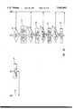
- FIGS. 1A-1Care partial cross-sectional views which schematically illustrate a conventional balloon catheter being placed within a vessel such as a coronary artery containing a blockage, and showing the manner in which the blockage is essentially removed by inflation of the balloon catheter.
- FIG. 2is a perspective illustration showing the system of the present invention, and in particular illustrating a syringe with tubing for connection to a balloon catheter, and a transducer means mounted on the syringe and electrically connected to an electronic controller.
- FIG. 3is a partial cross-sectional view of the syringe barrel that more particularly illustrates one presently preferred structure and method for placing the transducer means in fluid communication with the interior of the syringe and the tubing which is connected to the balloon catheter.
- FIG. 4is a functional block diagram which schematically illustrates the primary components of one presently preferred electronic circuit used in connection with the electronic controller.
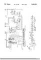
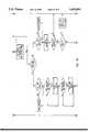
- FIGS. 5A and 5B taken togetherconstitute a detailed electrical schematic diagram which illustrate, as an example, the presently preferred embodiment and presently understood best mode for implementing the electronic circuit means of the system and method of the present invention.
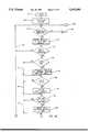
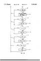
- FIGS. 6A through 6D taken togetherillustrate a flow chart showing one presently preferred method for programming the digital processor of the electronic circuit means in accordance with the method of the present invention.
- FIGS. 6E through 6Gtaken together illustrate a flow chart showing a second presently preferred method for programming the digital processor of the electronic circuit means utilized in the syringe system of FIGS. 2-5 in accordance with another method of the present invention.
- FIG. 7is a perspective illustration showing a second embodiment of the system of the present invention in which a transducer means together with an electronic controller are all mounted directly onto the syringe barrel so as to form a totally self-contained, disposable syringe system.
- FIG. 7Ais a perspective illustration of a portion of the syringe system of FIG. 7, with portions of the electronic controller shown in exploded perspective to more particularly illustrate certain details thereof.
- FIG. 7Bis an exploded perspective illustration which shows in greater detail some of the primary components and assembly constituting the electronic controller for the embodiment of the syringe system illustrated in FIG. 7.
- FIG. 7Cis an illustration of the digital readout display which particularly illustrates the nature of the information displayed thereon when utilizing the electronic control system and syringe of FIG. 7.
- FIG. 8is a functional block diagram which schematically illustrates the primary components of the digitally controlled electronic circuit used in connection with the syringe system of FIG. 7.
- FIGS. 9A and 9B taken togetherconstitute a detailed electrical schematic diagram which illustrate, as an example, the presently preferred embodiment and presently understood best mode for implementing the electronic circuit means of the syringe system of FIG. 7.
- FIG. 10illustrates a flow chart showing one presently preferred method for programming the digital processor of the electronic circuit means which is utilized for the syringe system in the embodiment of FIG. 7.
- FIG. 11is a perspective illustration showing yet another embodiment of the system of the present invention in which a RF transmission module is mounted to the syringe barrel.
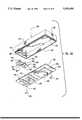
- FIG. 11ais a perspective illustration of a portion of the syringe system of FIG. 11, with portions of the RF transmission module shown in exploded perspective to more particularly illustrate certain details thereof.
- FIG. 11bis an exploded perspective illustration which shows in greater detail some of the primary components and assembly constituting the RF transmission module of the embodiment in FIG. 11.
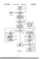
- FIG. 12is a functional block diagram which schematically illustrates the primary components of one presently preferred embodiment of the electronic circuit used in connection with the RF transmission module shown in FIG. 11.
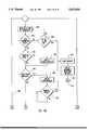
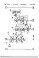
- FIG. 13is a functional block diagram which schematically illustrates the primary components of one presently preferred electronic circuit used in connection with the remote console shown in FIG. 11.
- FIGS. 14a through 14b taken togetherillustrate a flow chart showing one presently preferred method for programming the digital processor of the RF transmission module shown in FIG. 11.
- FIGS. 15a through 15f taken togetherillustrate a flow chart showing one presently preferred method for programming the digital processor of the remote console shown in FIG. 13.
- FIGS. 15g through 15j taken togetherillustrate a flow chart showing a second presently preferred method for programming the digital processor of the remote console shown in FIG. 13 in accordance with another method of the present invention.
- PTCAis a surgical procedure used for treating coronary artery disease wherein a balloon catheter 10 is inserted through an incision made in the groin or in the artery of an arm and is then advanced through the artery by means of a guide catheter and assisted by means of an x-ray sensitive dye. The balloon catheter 10 is advanced until it is located at the middle of the blockage 12. Once located at the middle of the blockage 12, the balloon of catheter 10 is then inflated (see FIG.
- the system and method of the present inventionare particularly useful in connection with the aforementioned PTCA procedure, the system and method of the invention are not intended to be necessarily limited to use in connection with PTCA. Rather, it is contemplated that the system and method of the invention will find useful application with respect to any procedure requiring the use of an inflatable balloon-type member.
- the inflation pressure which is applied to the balloon catheter 10is applied hydraulically by means of the syringe and connecting tubing which are all filled with a sterile liquid such as a solution of saline and contrast medium
- a sterile liquidsuch as a solution of saline and contrast medium
- the term "fluid pressure"is intended to apply either to a hydraulically or a pneumatically applied inflation pressure.
- FIGS. 2-5, 7-9 and 11-13The Presently Preferred Syringe System and Electronic Controller: FIGS. 2-5, 7-9 and 11-13.
- the system of the present inventionis comprised of a syringe that is connected to a balloon catheter or other balloon-type member through tubing.
- the syringeis used to apply fluid pressure to the balloon of the catheter or other balloon-type member through the tubing so as to inflate the balloon or balloon member when desired, and can also be used to deflate the balloon catheter or balloon member after it has been inflated for a selected duration.
- the systemis also comprised of a transducer means for sensing applied fluid pressure and for outputting an electrical signal proportional to the sensed fluid pressure.
- the transducer meansis thus preferably in fluid communication with the syringe and the tubing connected to the balloon catheter or other balloon-type member.
- the overall systemis generally designated at 14 and the syringe is generally designated at 16.
- the syringe 16is comprised of a barrel 22 typically molded from transparent plastic material to permit inspection of the contents thereof.
- a syringe plunger 24(FIG. 2) is slidably mounted within the barrel and is secured within the barrel 22 by means of a cap 34 which can be threaded onto or otherwise securely attached at the end of the barrel 22.
- the syringe plunger 24has a threaded portion 30 which mates with corresponding threads 32 (see FIG. 3) of end cap 34.
- plunger 24The proximal end of plunger 24 is provided with a soft rubber bulb 25 which engages the interior of barrel 22 in a fluid-tight fit such that by sliding the syringe plunger 24 further into the barrel 22, positive pressure exerted on the fluid contained within syringe 16 and connecting tubing 38 will be applied to the balloon catheter which is connected to the tubing 38 by means of a rotatable luer connector 39. Similarly, by withdrawing the syringe plunger 24 toward the rear of the barrel 22, the positive pressure exerted on the balloon catheter will be released.
- Rapid movement of the syringe plunger 24is accommodated by means of a trigger mechanism comprising a spring-activated trigger 28 which can be retracted into handle 29 so as to disengage the threads 30 from the corresponding threads 32 of cap 34.
- a trigger mechanismcomprising a spring-activated trigger 28 which can be retracted into handle 29 so as to disengage the threads 30 from the corresponding threads 32 of cap 34.
- Thispermits the plunger 24 to freely slide in either direction within the syringe barrel 22.
- the threads 30are then permitted to engage the corresponding threads 32 of cap 34 so that thereafter the syringe plunger 24 can only be advanced or retracted by screwing the plunger 24 either clockwise or counter clockwise, respectively.
- rapid application or release of pressure applied to the balloon cathetercan be accomplished by compressing the trigger 28 against handle 29 followed by movement of the syringe plunger 24 to the position desired for the approximate pressure to be applied. This can then be followed by release of the trigger 28 and screwing the plunger 24, which will permit a slow, gradual adjustment of the syringe plunger 24 to the exact pressure that is desired.
- the transducer means of the system of the present inventionis generally designated in FIGS. 2 and 3 at reference numeral 18.
- the body of syringe barrel 22has a small housing 40 formed at the leading end of the barrel as an integral part of the syringe barrel 22.
- the housing 40communicates through a small circular opening 50 formed in the sidewall of syringe barrel 22 with the interior of syringe barrel 22 for the purpose of providing fluid communication from the interior of barrel 22 and connecting tubing 38 to the transducer means, as hereinafter more fully described.
- fluid communicationis intended to mean the pneumatic or hydraulic transmission (direct or indirect) of fluid pressures exerted within the syringe barrel 22 and connecting tubing 38 to the transducer means so that such fluid pressures can be sensed by the transducer means.
- Direct transmission of such fluid pressureswould occur, for example, when a diaphragm of a piezoresistive semiconductor transducer is placed into contact (either pneumatically or hydraulically, or a combination of both) with a fluid contained in a closed system, as would be the case in the preferred embodiments illustrated and described herein.
- Indirect transmissioncould be said to occur, for example, where the transducer means is coupled to a diaphragm that in turn contacts the fluid contained in a closed system.
- the transduceris shown as preferably comprising a piezoresistive semiconductor integrated circuit 42 which provides a Wheatstone bridge, as shown in the detailed electrical schematics at FIGS. 5B and 9B at the corresponding reference numeral.
- Transducer 42is in turn attached to a small ceramic substrate 44 which contains additional circuitry for providing temperature compensation and calibration of the transducer 42, and to which is connected the electrical cable 46.
- the end of electrical cable 46, ceramic substrate 44 and piezoresistive semiconductor transducer 42are assembled as illustrated in FIG. 3 and placed within housing 40, and then secured by a suitable potting compound and permanently enclosed by means of the cap 48 placed on top of the housing 40. In this manner, the entire transducer assembly is formed as an integral attachment to the syringe barrel 22. Stops 26 (see FIG. 2) are formed on the syringe plunger 24 so as to prevent the bulb 25 of syringe plunger 24 from being inserted to the point where it would otherwise close off the circular opening 50.
- the small circular opening 50may be filled, for example, with a silicone gel which will permit transmission of the fluid pressures exerted by means of syringe 16 through the circular opening 50 so that such pressures can be sensed by transducer 42, while at the same time isolating the integrated circuit 42 and substrate 44 from coming into contact with fluid contained in the syringe barrel 22.
- Bourdon-tube gaugesare mounted to the syringe barrel. These types of gauges typically include brass fittings which are in direct contact with the contrast media in the syringe. As a result, highly toxic substances, such as copper sulfate and heavy metal residuals, such as lead, have been found to be present in the contrast media as a result of chemical interaction of the brass fitting with the contrast media. While this is not harmful so long as the balloon is not ruptured, if a rupture does occur this toxic substance is released into the patient's cardiovascular system.
- One advantage of the above-described syringe and transducer meansis the elimination of materials, such as brass, from which such toxic substances are derived. Furthermore, contact of any sort between the contrast media and the transducer and related circuitry is completely prevented, as noted above, by the silicone gel that isolates such from the contrast media while still providing effective fluidic coupling to the transducer diaphragm.
- the transducer meanshas been illustrated and described as a piezoresistive semiconductor which is integrally mounted to the syringe barrel 22, it should be appreciated that the preferred embodiment is illustrative only and is not to be construed as limiting the scope of the invention.
- the semiconductor transducercould be located at the end of connecting tubing attached through a T-connector to tubing 38 and could therefore be located at a position remote from the syringe 16, as for example on an I.V. stand or mounted as part of the electronic circuitry contained inside of controller 20.
- transducer meanscould also comprise transducer types other than the piezoresistive semiconductor type illustrated and described in the preferred embodiment, as for example conventional strain gauge transducers which have been known and used in the art for many kinds of different pressure monitoring applications, or fiberoptic transducers.
- the electronic circuit means and display means of the system of the present inventionare illustrated in the preferred embodiment as comprising part of controller 20.
- the specific electronic circuitry which is used for implementing the controller 20, and its method of use for monitoring, displaying and recording PTCA data as illustrated in FIGS. 2-5is set forth in U.S. Pat. No. 5,135,488 which is incorporated herein by reference, in its entirety.
- FIGS. 7-9are identical to FIGS. 7-9.
- FIG. 7illustrates an alternative embodiment of the syringe system of the present invention.
- the electronic circuit means and display means of the system of the present inventionare designed so as to comprise part of a miniaturized controller, which is generally designated at 20a, that is battery powered and is mounted directly onto the syringe 16 so as to form a totally self-contained, disposable syringe system 14a.
- the specific electronic circuitry which is used for implementing the controller 20a, and its method of use for monitoring, displaying and recording PTCA data as illustrated in FIGS. 7-10is set forth in U.S. Pat. No. 5,201,753, which is incorporated herein by reference, in its entirety.
- FIG. 11illustrates yet another alternative embodiment of the present invention that utilizes an RF transmission means to wirelessly transmit inflation data from the inflation syringe to a remote console means, where the data is then further processed, displayed and/or recorded.
- the syringe system of this embodimentdesignated generally at 14b, includes a syringe, generally designated at 16, that is essentially identical in all respects to the syringe 16 described above in connection with FIGS. 2 and 3 and therefore will not be described in further detail here.
- Syringe system 14balso includes a transducer means, as for example a piezoresistive semiconductor transducer 42 (described in connection with FIG. 11A below), for sensing a fluid pressure and for outputting an electrical pressure signal proportional to the sensed fluid pressure.
- a transducer meansas for example a piezoresistive semiconductor transducer 42 (described in connection with FIG. 11A below), for sensing a fluid pressure and for outputting an electrical pressure signal proportional to the sensed fluid pressure.
- the syringe system 14bincludes an RF transmission means, as for example an RF transmission module 400 mounted to the syringe 16, for receiving the electrical pressure signal and for wirelessly transmitting transmission data that is representative of the electrical pressure signal via a selected radio frequency signal.
- the RF transmission module 400is permanently mounted to the end of the syringe barrel 22.
- FIG. 11further illustrates how the syringe system 14b includes a remote console means, as for example remote console 402, that is positioned away from the syringe 16 and its attached RF transmission module 400.
- the remote console 402is capable of wirelessly receiving the transmission data that is transmitted by the RF transmission module 400, and is further capable of electronically processing the transmission data so as to derive and so as to display or record therefrom digital inflation or deflation data that is representative of the magnitude of the fluid pressure applied to the balloon member as well as the length of time the fluid pressure is applied to the balloon member.
- the syringe system 14balso includes a display means, such as graphics display 404, that is electrically connected to, and preferably formed as an integral part of, the remote console 402.
- the graphics display 404is capable of outputting a visual display of the digital inflation or deflation data derived by the remote console 402.
- the RF transmission module 400has a control panel 406 that is equipped with a switch means for selectively controlling the remote console 402 to perform at least one of a plurality of optionally selectable functions.
- the switch meansis comprised of a first switch means, as for example menu switch 408, and a second switch means, as for example select switch 410.
- the menu switch 408allows the syringe system 14b user to select a menu display for presentation on the graphics display 404.
- This menu displayhas a plurality of optionally selectable functions that can be performed by the remote console 402.
- the RF transmission module 400allows the system user to selectively monitor the data that corresponds to the inflation or deflation of the balloon catheter and to selectively record and display historical data corresponding to past inflations--by selectively operating the switches on the control panel 406.
- the RF transmission module 400is conveniently positioned on the syringe 16 so as to allow the user to control the remote console 402 and view inflation data while, at the same time operating the syringe 16. Further, the RF transmission module 400 provides the user with a greater level of freedom in how the syringe can be handled and positioned during an inflation procedure because there is no need for any bulky cable connections between the syringe and the remote console 402. Similarly, there is no need to sterilize (or maintain the sterility of) a cable and/or cable connectors that would otherwise be used to interconnect the syringe 16 and the remote console 402.
- the graphics display 404is illustrated as being integrated in the remote console 402.
- Remote console 402can be located on a stand 425 or similar device, and be positioned at any point where it can be seen by the cardiologist or clinician using the inflation syringe 16.
- the remote console 402can be switched on or off using a conventional switch located on the console (not shown).
- the remote console 402is plugged into a conventional AC wall outlet, and as will be discussed further, the remote console 402 is also equipped with a battery-backed memory which provides an internal clock and timer and which retains data in memory after the remote console 402 is switched off.
- the specific electronic circuitry which is used for purposes of receiving transmission data sent by the RF transmission module 400, and for processing the transmission data,is contained within the remote console 402 and is more particularly illustrated in FIG. 13, which is described in further detail below.
- the display meansis preferably comprised of a type of graphic display 404 that is capable of displaying, in an easy to read format, pressure information 412, and time information 414.
- the pressure portion 412 of the displayis also used for purposes of inputting selected control data, such as maximum positive pressure desired in connection with an inflation, and selection of pressure units.
- the time portion 414 of the displayis also used for inputting selected control data such as the maximum duration for an applied positive pressure.
- the remote console 402 and display 404, and the information displayed thereon,is controlled via the selective operation of the menu and select switches 408, 410 disposed on the RF transmission module 400.
- a second menu switch 416 and a second select switch 418are disposed on a second control panel designated generally at 420, that is positioned on the front panel portion of the remote console 402.
- These switches 416, 418operate identically to the corresponding switches 408, 410 that are disposed on the RF transmission module 400, and any function performed by the switches 408, 410 will also apply to switches 416, 418.
- the remote console 402may be optionally controlled by a user via the second control panel 420.
- the display 404may be configured in a variety of ways so as to display the information generated by the remote console 402. For instance, time and pressure information may optionally be displayed graphically and/or alphanumerically. Also, as is further illustrated in FIG. 11, remote console 402 is equipped with a conventional connector 422 for a printer cable 424 so that data which is recorded by the remote console 402 can be selectively (via the menu and select switches 408, 410) printed out for permanent documentation and later reference.
- the RF transmission module 400is preferably permanently mounted to the syringe barrel 22.
- the transmission module 400is comprised of an upper housing assembly, generally designated at 426, and a lower housing assembly, generally designated at 428.
- Upper housing assembly 426 and lower housing assembly 428are joined together, with the lower housing being mounted directly to the end of the syringe barrel 22.
- FIGS. 11A and 11Btaken together.
- the lower housing assembly generally designated at 428is preferably formed as a single molded plastic part.
- the lower housing assembly 428is formed with a generally square shaped box portion 430 which is designed to dimensionally fit over the correspondingly shaped transducer housing 432 which is molded as part of the syringe barrel 22.
- the integrated circuit which includes the transducer 42is mounted directedly onto a ceramic substrate 44 and is electrically connected to conductive pads 436.
- a rectangular opening 438is provided in the square shaped member 430 which fits over the correspondingly shaped transducer housing 432.
- the rectangular opening 438in turn is intended to receive a conductive elastomeric or rubber member 442 such that when the member 442 is seated within the rectangular opening 438, the bottom of member 442 will contact the conductive pads 436.
- the conductive rubber member 442is comprised of a material that is known in the art as a "zebra" or "Z" strip.
- the conductive rubber Z strip 442serves as a means for providing an electrical interconnection between ceramic substrate 44 onto which the transducer 42 is mounted, and the other electronic components of the RF transmission module 400 which are carried on the printed circuit board 446. More particularly, the conductive rubber member 442 contacts and provides electrical interconnection between the conductive pads 436 on the ceramic substrate 44 and the corresponding conductive pads 444 that are provided on one side of the printed circuit board 446 (shown in FIG. 11B).
- FIG. 11Bit is shown how the upper housing assembly 426 of RF transmission module 400 carries the printed circuit board 446 onto which is mounted the microprocessor circuit 448, a battery 450, and other electronic components which are required for the circuitry of the RF transmission module 400, as illustrated and described in more detail in connection with FIG. 12.
- Power meanssuch as a battery 450, provides electrical power to the transducer 42 and the electronics contained within the RF transmission module 400.
- the upper housing assembly 426comprises a generally rectangular shaped molded piece 458 that is provided with a rim 452 that extends around its entire bottom periphery and, which is designed to fit into a corresponding channel 454 which is formed around the upper periphery of the lower housing assembly 428 (shown in FIG. 11A).
- the two housing assemblies 426 and 428can be firmly bonded together and the entire RF transmission module assembly 400 is then permanently mounted and bonded onto the syringe barrel 22 (as is illustrated in FIG. 11).
- the lower housing assembly 428is provided with a corresponding cylindrical shape 456 (best seen in FIG. 11A) on its underside so that the lower housing assembly 428 conforms to the cylindrical shape of the syringe barrel 22.
- the upper housing assembly 426 and the lower housing assembly 428are both molded from an opaque plastic material.
- the RF transmission module 400is preferably comprised with a menu switch 408 and a select switch 410 (shown in FIGS. 11 and 11A).
- FIG. 11Billustrates how the menu and select switches 408, 410 are each preferably comprised, for example, as elastomeric button switches.
- menu switch 408has an upper cylindrical extension 460 that extends through an opening in well 462 which is formed in the upper rectangular member 458 so that the cylindrical portion 460 can be finger-actuated by pressing.
- the menu switch 408also is comprised of a means for preventing entry of liquids at the switch 408, as for example an integral conically shaped skirt 464 which terminates in a generally square shaped base 466.
- Base 466entirely covers the base of well 462 so that when the entire assembly is completed, the switch 408 is fluid tight and will thus not permit water, saline solution or other liquids to enter the RF transmission module 400 through the location of the actuable button 460. Accordingly, the base 466 extends downwardly and rests again on the upper side of the printed circuit board 446 so that the actuable button 460 is held in a position which extends through the opening of well 462 into the position as shown in FIG. 11A but at the same time the base 466 also seals the well 462.
- the button 460When the button 460 is pushed downwardly, the circular base 468 of the button switch 460 is pushed into contact with the conductive pad (not shown) on the upper side of the printed circuit board 446 thereby making the necessary electrical contact to activate the electronic components, as hereinafter more fully described.
- the elastomeric properties of conical skirt 464will return the button 460 upwardly when it is released.
- the select switch 410is preferably constructed in a similar manner, and like parts are signified with like numbers having a prime sign.
- the microprocessor circuit 448is mounted to the underside of printed circuit board 446 and a battery 450 is mounted over the microprocessor 448 on the same side of the printed circuit board 446.
- the elastomeric button switch 460, 460' portions of the menu and select switches 408, 410are placed into the wells 462, 462' and then the printed circuit board 446 is placed over the square base portions 466, 466'.
- Pins or anchors 470are then inserted through corresponding holes 472 in the printed circuit board 446 and into corresponding receiving holes 474 in the top portion of the upper housing assembly 426.
- the pins 470are bonded or otherwise anchored into the holes 474 such as by a press fit, threaded fit, or other appropriate means.
- the electronic circuitry which comprises the RF transmission module 400is illustrated in further detail in the functional block diagram of FIG. 12.
- the RF transmission module 400comprises, by way of example, means for amplifying and conditioning the electrical pressure signal output by the transducer 42; means for converting the amplified pressure signal from an analog to a digital form; digital processor means for processing the digital form of the electrical pressure signal so as to derive therefrom transmission data; data memory means for storing the transmission data derived by the digital processor means; program memory means for storing machine-readable instructions utilized by the digital processor means to derive and store the transmission data for transmission; and RF transmission circuit means for wirelessly transmitting the transmission data as an RF signal having a predetermined radio frequency.
- the transducer 42is essentially the same as the transducer previously described in connection with the embodiment of FIGS. 2-5.
- Transducer 42is electrically connected as schematically shown at 500 (by means of the conductive rubber Z strip 442 described above) to the circuit components which serve as the amplifier and signal conditioning circuitry as generally designated at 502 in FIG. 12.
- the presently preferred embodiment of the amplifier and signal conditioning circuit 502, and the oscillator 449 and power circuit 450are essentially identical to the corresponding circuits contained in the functional block diagram of FIG. 8, and the accompanying electrical schematic diagram of FIGS. 5B and 9B (and more particularly, the circuit enclosed by dashed box 86 in FIGS. 5B and 9B). The detailed description directed to those circuits will not be repeated here.
- the amplified analog electrical pressure signalis then input as schematically represented at line 504 to a control port 506 which is internal to the microprocessor's 448 integrated circuitry.
- control port 506the signal is input as schematically indicated at line 510 to an analog to digital (A/D) convertor 512 which is also internal to the microprocessor's integrated circuitry.
- A/D convertor 512serves as a means for converting the amplified signal from the analog to a digital form.
- microprocessor 448The particular integrated circuit which is used for microprocessor 448 is the same as microprocessor 290 identified above in FIG. 9A as integrated circuit U1 and which is also further identified in Table II at the end of the detailed description. It should be appreciated that the particular circuit components and circuit design are intended merely as an example of the presently preferred embodiment and the presently understood best mode of implementing the overall functions which are represented by the block diagram of FIG. 12. Of course other circuit designs could be devised that would work satisfactorily, using either software-based digital processing circuitry or hardware-based circuit designs.
- the digitized signalis input as schematically indicated at line 514 to the digital processor 516.
- the digital processor 516is controlled by the programmed instructions stored in program memory (ROM) 518 and which are communicated as schematically illustrated at lines 522 through a latch 520 to the digital processor 516.
- the particular program instructions carried out by the digital processor 516are more particularly illustrated and described in reference to the flow chart of FIGS. 14A and 14B, as hereinafter more fully described in Section II.
- the program instructionsare addressed by the digital processor 516, as schematically represented by the lines 524 through latch 520.
- the instructions stored in program memory 518are utilized by the digital processor 516 to derive from the digitized transducer signal transmission data which represents the applied inflation pressure which is being exerted by the syringe 16 on the balloon of the catheter. This is designed to occur in real time as the pressures are being applied. At the same time, the duration of the applied inflation pressure is timed, and transmission data representative of the duration is generated. The digital processor 516 then causes the transmission data, representative of pressure and time magnitudes and other control and status information (discussed below in connection with FIGS. 14A and 14B), to be transmitted wirelessly via an RF transmission signal to the remote console 402.
- the data memory means of the RF transmission module 400is provided, in the embodiment of FIG. 12, by a scratch pad random access memory (RAM) 526 which is also accessed through latch 520 by digital processor 516.
- the digital data memory 526is used to record and store the various transmission data derived from the electrical pressure signal.
- the transmission datais queued in memory 526 so as to assemble data packets which are subsequently transmitted as transmission data to the remote console 402.
- a timer 530also communicates as schematically indicated by line 532 with the digital processor 516, and is internal to the integrated circuitry contained on the microprocessor circuit 448.
- Serial data receivers and drivers 534also communicate as schematically illustrated at lines 536 and 538 with the digital processor 516, and are internal to the integrated circuitry of the microprocessor 440.
- the serial data receivers and drivers 534can be used for outputting a variety of data through a serial communication output/input line as schematically indicated at lines 540, 542 and 544.
- the microprocessor circuit 448monitors the status of the menu switch 408 and the select switch 410 via the control port 506, as is schematically illustrated at lines 546 and 548. In this manner, the microprocessor 448 can detect when a user has depressed either of the switches 408, 410 and then transmit that status information to the remote console 402 via a transmission data packet. As discussed generally, the functions associated with the menu and select switches 408, 410 allow the user to control the operation of the remote console 402, which is described in further detail below in connection with FIG. 13.
- the microprocessor 448is programmed to output pressure and time values, the status of the menu and select switches 408, 410, and other control and status information to the control port 506, as is schematically illustrated at line 550.
- This transmission datais then sent to the RF transmission circuit means, as for example circuitry that is schematically illustrated within the dotted box 552, via line 554.
- the circuitry contained within box 552takes the transmission data and transmits it to the remote console 402 via an RF signal.
- the RF transmission circuit meansis comprised of RF transceiver circuitry 556 capable of implementing the EIA CEBus (IS-60) Radio Frequency (RF) physical layer utilizing a spread spectrum technology which conforms with Federal Communications Commission Part 15 rules.
- the RF transceiver circuitry 556is comprised of a Spread Spectrum CarrierTM RF Transceiver integrated circuit having the tradename of CELinx rf, which is manufactured and sold by Intellon Corporation of Ocala, Fla. This Spread Spectrum CarrierTM circuit, covered in U.S. Pat. No. 5,090,024, is based on a direct sequence method of spreading the digital data into a broad spectrum or band.
- Each bit of the digital signalis spread into a unit symbol using a forward or reverse sequence of seven substrates each consisting of a 360 bit chipping sequence.
- the bit chipping sequenceapproximates a forward or reverse frequency sweep from 4.2 to 6.3 Megahertz.
- This sequenceis further modified by a 15-bit phase modulation function.
- the combined effect of the 360 bit chipping sequence, the 7 substate sequence and the 15-bit phase modulation functionis an even spreading of the digital information across a 2.1 Megahertz band.
- the use of a spread spectrum methodallows the system to benefit from increased signal gain inherent in processing the signal using spreading and despreading algorithms to encode the transmitted signal. This processing gain allows the system reliability to increase without increasing the power output from the transmitter.
- the microprocessor circuit 448encodes and formats the transmission data and then passes the transmission data to the RF transceiver module 556 via line 554.
- Microprocessor circuit 448also monitors and controls the operation of the RF transceiver module 556, as is schematically shown at line 558.
- RF transceiver module 556under the control of microprocessor circuit 448, will then transmit the transmission data to the remote console 402 via the predetermined radio frequency, as discussed above.
- power for the microprocessor 448 and other circuit componentsis supplied by the battery 450 which is also illustrated in connection with the upper housing assembly 426 of FIG. 11B.
- the battery 450permits elimination of any connecting cables or the like so that the syringe system 14b is totally self-contained and does not require outside connection to any other power source. This advantageously simplifies the overall system 14b and makes maintaining sterility of the syringe system 14b an easier task throughout the entire procedure.
- the remote console 402comprises, by way of example, RF receiver circuit means for receiving the transmission data transmitted by the RF transmission module; second digital processor means for monitoring the transmission data transmitted by the RF transmission module 400 and for processing the received transmission data so as to derive, store and display digital inflation or deflation data which represents the magnitude of the applied pressure and the duration of time the pressure is applied to the member; second data memory means for storing the digital inflation or deflation data derived by the second digital processor means; and second program memory means for storing machine-readable instructions utilized by the second digital processor means to monitor the transmission data and to derive, store, retrieve and display the digital inflation or deflation data.
- the RF receiver circuit meansis comprised of RF receiver circuitry contained within the dotted box generally designated at 560.
- the RF receiver circuitryis capable of receiving a signal that is transmitted by the RF transmission circuitry 556 of the RF transmission module 400, and thus is capable of implementing the EIA CEBus (IS-60) Radio Frequency (RF) physical layer utilizing a spread spectrum technology conforming with the FCC Part 15 rules.
- the RF receiving circuitryis comprised of the same CELinx rf transceiver 556 manufactured by Intellon Corporation previously described.
- the RF receiver circuit 562receives the transmission data, demodulates the transmission data, and then passes the transmission data to second digital processor 564, via line 566.
- the digital processor 564in addition to accepting the received transmission data, also monitors and controls the RF receiver circuit 562, as is shown at line 568.
- the second digital processor 564is controlled by machine-readable instructions stored in second program memory means, as for example program memory 570, which are communicated by a data bus, schematically illustrated as 572, running between digital processor 564 and program memory 570.
- program memory 570which are communicated by a data bus, schematically illustrated as 572, running between digital processor 564 and program memory 570.
- the particular program instructions carried out by the digital processorare more particularly illustrated and described in reference to the flow chart of FIGS. 15A-15J which will be described in greater detail below in Section II.
- the program instructionsare addressed by the digital processor 564 through latch circuit 574 and the address bus represented at line 576.
- the instructions stored in program memory 570are utilized by the second digital processor 564 to derive from the transmission data transmitted from the RF transmission module 400 the fluid pressures applied by the syringe 16 to the balloon catheter and to display the sensed pressures, and the durations of the pressure, on the graphic display 404.
- the applied fluid pressuresare also automatically recorded by second digital processor 564 and stored in the second data memory means, as for example the battery-backed data memory and timer 580.
- the output of the digital data to the graphic display 404is transmitted by way of a data bus which is used to drive the graphic display 404.
- the second digital processor 564can also be programmed to display the positive inflation pressure which is output on the graphic display 404 in units of either atmospheres or pounds per square inch as selected by the system user by means of the menu and select switches that are disposed on the RF transmission module 400 (408, 410) or on the remote console 402 (416, 418).
- Second digital processor 564can also be utilized, according to the programmed instructions contained in program memory 570, to monitor and thus assist in the control of the maximum positive inflation pressure to be applied to the balloon catheter by inputting on the graphic display 404 a maximum positive pressure using the menu and select switches 408, 410. Once the maximum positive inflation pressure is reached, the second digital processor 564 will cause a portion of the graphic display 404 to flash, thereby signaling the system user that the maximum positive inflation pressure has been reached. This advantageously assists the system user in more carefully controlling and identifying the procedure used with respect to each inflation event.
- a selected duration for which positive inflation pressure is to be applied to the balloon cathetercan also be input on the graphic display 404, again by using the menu and select switches 408, 410. Accordingly, the programmed instructions contained in program memory 570 will thereafter cause the second digital processor 564 to begin counting the duration once positive inflation pressure begins to be applied. The count will be output by processor 564 on the graphic display 404 which will flash once the selected duration has been reached, thereby signaling the system user that positive inflation pressure has been applied for the desired length of time. Again, this significantly enhances the ability of the overall system to carefully assist in controlling the inflation procedures according to the selected parameters.
- Data memory 580is battery-backed so as to retain all data stored therein even when the remote console 402 is switched off, and so as to provide an internal timer for the date and time data and for clocking any selected maximum duration times input as described above.
- Each of the control parameters which are input on the graphic display 404are input and stored in the data memory 580. In this manner, the appropriate control parameters are utilized by the program stored in the data memory 580 for later reference.
- the second digital processor 564will automatically time the duration of the positive pressures and this information will likewise be recorded and stored in the data memory 580 for later reference, along with a numerical identification input to the graphic display 404 which identifies whether the particular inflation event is the first time the balloon catheter has been inflated or whether the inflation is a subsequent inflation. In this manner, each time the balloon catheter is inflated it is discretely identified and the maximum inflation pressure and time duration data corresponding to that inflation event are not only displayed but are also automatically recorded and stored in the data memory 580.
- a latch circuit 574is used to control the gating of address data from second digital processor 564 to the respective memories 570 and 580 and graphic display 404 as is conventional in the art.
- system of the present inventionalso provides for output of the recorded data from second digital processor 564 through serial data lines 582 and 584 to a serial data receiver and driver circuit 586, which in turn is connected to a printer port 422 to which printer cable 424 (shown in FIG. 11) is connected.
- serial data receiver and driver circuit 586which in turn is connected to a printer port 422 to which printer cable 424 (shown in FIG. 11) is connected.
- the supply voltage used for driving the circuitry contained within the remote console 402is supplied by means of a transformer (not shown) which is connected at its output to a full wave bridge rectifier (not shown) in a manner similar to that illustrated and described for controller 20 in FIG. 4.
- FIGS. 6A-6G and FIG. 10illustrate the presently preferred embodiments of the instructions which may be utilized to control the processor means 90 or 290, respectively.
- FIGS. 14A through 14B, and FIGS. 15A through 15Jillustrate the presently preferred embodiments of the instructions which may be utilized to control the digital processors 448 and 564 respectively.
- FIGS. 6A-6G1.
- controller 20is programmed to carry out monitoring, display and recording of PTCA data as illustrated in FIGS. 6A through 6G is described in detail in U.S. Pat. No. 5,135,488, incorporated herein by reference in its entirety.
- miniaturized controller 20ais programmed to carry out monitoring, display and recording of PTCA data as illustrated in FIG. 10 is described in detail in U.S. Pat. No. 5,201,753, incorporated herein by reference in its entirety.
- the embodiment of the program instructions as illustrated in the flow chart of FIGS. 14A and 14Bis particularly designed for programming the microprocessor 448 described in connection with the RF transmission module 400 of the syringe system 14b previously discussed in conjunction with FIGS. 11 through 13.
- step 650the system is initialized and the appropriate program instructions are loaded into the microprocessor 448.
- the microprocessor 448then moves to step 652 at which time a status flag indicating that the RF transmission module 400 has been powered on is transmitted as transmission data to the remote console 402.
- the microprocessor 448then performs a series of diagnostic steps so as to insure that both the RF transmission module 400 and the transducer 42 are properly interfaced and functioning correctly.
- the microprocessor 448checks to make certain that the transducer 42 is properly connected to the rest of the circuitry contained on the RF transmission module 400. If not, a status flag indicating "no transducer" is transmitted to the remote console 402 at step 656. If transducer 42 is properly connected, microprocessor 448 proceeds to step 658 and checks the excitation voltage of the transducer 42. If the excitation voltage is incorrect, a status flag indicating "excitation error" is transmitted to the remote console 402 at 660.
- step 662the N-Leg voltage of the transducer 42 is checked. If incorrect, a status flag indicating "N-Leg error" is transmitted to the remote console 402 at 664. If N-Leg voltage is correct, microprocessor 448 proceeds to step 666 and checks the P-Leg voltage of the transducer 42. Again, if incorrect, a status flag indicating the error is transmitted to the remote console 402 at step 668. If correct, the microprocessor 448 proceeds to step 670.
- the microprocessor 448determines the zero pressure reading of the transducer 42 and compares that value to a predetermined offset range. If the value falls outside of that range, a status flag indicating an "open system error" is transmitted to the remote console 402 at step 672. If the value falls within the range, the microprocessor 448 proceeds to step 676, shown on FIG. 14B. At step 676, the microprocessor 448 checks the battery 450 voltage level. If the voltage level is sufficient, the microprocessor 448 proceeds to step 680. If the voltage level is below a selected point, the microprocessor 448 warns the user by setting a "low battery status" flag at step 678, which will subsequently be transmitted to the remote console 402 as transmission data, before continuing to 680.
- the microprocessor 448begins to monitor the electrical pressure signal generated by the transducer 42, which signal has been digitized and input to the microprocessor 448 as previously described in connection with FIG. 12. Thus, the microprocessor 448 proceeds to step 682.
- This portion of the program instructionsmonitors the status of the switches (menu 408 and select 410) that are disposed on the control panel 406 of the RF transmission module 400.
- the microprocessor 448checks to see if the menu button 408 is being pressed by the user. If not, the processor proceeds directly to step 686. If menu button 408 is pressed, the processor 448 sets the "menu button” flag at step 684 and then proceeds to step 686.
- microprocessor 448determines whether the select button 410 is being pressed by the user. If not, the processor proceeds to step 690. If select button 410 is pressed, processor sets the "select button” flag at step 688 before proceeding to step 690.
- the microprocessor 448determines if the menu button and select button 408, 410 are being pressed simultaneously. Pressing both buttons simultaneously causes the RF transmission module 400 to power off. In that case, the processor 448 proceeds to step 698 and transmits a "powering off" transmission data packet to the remote console 402. The processor 448 will then delay for a period of time, as is indicated at step 700, and will then halt and await a new power-on signal at step 702.
- the processor 448will proceed to step 692 and queue up the transmission data (i.e., pressure value, time value and/or status data).
- the processor 448then, at step 694, assembles a data packet containing the transmission data, and proceeds to transmit the data packet at step 696 to the remote console 402.
- the data packetwill include the current pressure value as well as pressure values from the previous two or three transmissions. This insures that pressure values are not inadvertently lost if, for instance, a particular transmission fails.
- the processor 448returns to step 676 and continues to process, as described above.
- the RF transmission module 400will, once it has powered on and run through a diagnostic procedure, continuously transmit transmission data to the remote console 402. This will continue until the user simultaneously presses the menu and select buttons 408, 410 and thereby powers off the RF transmission module 400.
- FIGS. 15A-15Fillustrate the presently preferred embodiment of the instructions which may be utilized to control the second digital processor 564 contained within the remote console 402 discussed above in conjunction with FIG. 13.
- step 710when the remote console 402 is powered on, the program starts as indicated at step 710 and then moves to step 712 which causes the system to initialize.
- the appropriate program instructionsare loaded from program memory 570 into the digital processor 564 (shown in FIG. 13).
- the systemthen moves to step 716 which causes the processor 564 to read the data contents of the RF transceiver circuit (562 in FIG. 13).
- the processor 564then, in step 718, checks whether the contents of the RF transceiver 562 constitutes valid transmission data that has been transmitted by the RF transmission module 400. If the transmission data is not valid, the process will move as indicated at flag 736 to the portion of programmed instructions illustrated in FIG. 15B.
- the processor 564will move to step 722, and check whether the RF transmission module 400 has transmitted a "power on" signal. If so, the processor will cause a message to be output on the graphic display 404 signifying that the syringe has been activated at step 724, and then proceed to step 726. If a power on signal has not been transmitted, the processor 564 will proceed directly to step 726, where it will check to see if any other errors have been detected and transmitted by the RF transmission module 400. If there are not any other errors indicated, the processor moves as indicated at flag 728 to the portion of the programmed instructions illustrated in FIG. 15D, described in further detail below.
- the processor 564will cause a corresponding message to be displayed on the graphic display 404 indicating that a particular error has occurred at step 730.
- the processorwill then await acknowledgement from the user by waiting for the user to press the menu switch 408 or 416, as is indicated at step 732. Once the user has depressed the menu switch 408 or 416, the process will move, as is indicated at flag 736, to the portion of the programmed instructions illustrated in FIG. 15B.
- the processor 564will cause a message to be displayed on the graphic display 404 signifying that the RF transmission module 400 is not communicating with the transducer 42 and instruct the user to press the menu switch 408.
- the processorthen moves to step 742 to check whether the menu switch 408 has been activated and if not returns to step 716 as schematically illustrated at 738 and continues in that loop until the menu switch 408 or 416 is activated by the user.
- step 742the processor then moves to step 744 and causes the graphic display 404 to display a message inquiring whether the inflation data previously recorded by the system 14b is to be scrolled at the graphic display 404. If the system user desires to review the previously recorded inflation data, the select switch 410 or 418 is activated and the processor 564 then proceeds to step 746 which causes all of the previously recorded inflation data for each inflation event to be retrieved in sequence and displayed. If at step 744 the system user does not wish to scroll the previously recorded inflation data, the menu switch 408 or 416 is activated which causes the processor 564 to skip step 746 as schematically illustrated at line 745 so as to proceed with the next inquiry as represented at step 748.
- the systemcauses a message to be displayed on the graphic display 404 inquiring whether previously recorded inflation data which has been previously stored in the data memory 580 is to be cleared. If the select switch 410 or 418 is activated this causes the processor 564 to clear the previously recorded inflation data from data memory 580, as indicated at step 750. If the previously recorded inflation data is not to be cleared from data memory 580, the menu switch 408 or 416 is activated which causes the system to skip step 750 and to move to the next inquiry as represented at step 752.
- the systemcauses the graphic display 404 to display an inquiry with respect to whether an upper limit is to be set with respect to the maximum positive inflation pressure to be applied with respect to the next inflation event. If so, the select switch 410 or 418 is activated and is used to input the selected maximum positive inflation pressure through the data transfer bus 572 (FIG. 13), to the data memory 580 for later reference, at step 754. If a maximum inflation pressure is not selected at step 752, the menu switch 408 or 416 is activated which causes the system to skip step 754 and move to the next inquiry, via flag 756, as represented at step 758 (FIG. 15C).
- step 758the system displays a message at the graphic display 404 inquiring whether the maximum duration for application of positive pressure is to be selected. If so, the select switch 410 or 418 is again activated which causes the system to move to step 760 and the select switch 410 or 418 is then used to input at the graphic display 404 the selected duration. This selected duration is input by means of the corresponding graphic display circuitry 578 (see FIG. 13) through the data transfer bus 572 to the data memory 580 for later reference.
- the systemcontinues to inquire whether the current time and date are to be displayed, as represented at steps 762 and 766, respectively. If so, by utilizing the select switch 410 or 418 as described above, the current date and time may be entered at the graphic display 404. However, the internal clock that is part of the circuitry in processor 564 will typically make it unnecessary to enter these parameters. The system then moves through the series of steps represented at 770, 772, 774, and 776 where it determines the pressure units to be displayed at the graphic display 404 as well as determining whether data is to be printed. After the print inquiry has been responded to by utilization of the appropriate menu or select switch 408, 416 or 410, 418 respectively, the system returns as illustrated at line 778 to step 716.
- the portion of the program instructions which are carried out according to the flow chart of FIGS. 15A-15Cpertains to that part of the program which permits a series of optionally selectable functions to be sequentially displayed for purposes of inputting various control parameters which are later utilized in displaying and automatically recording the data, as well as utilizing these control parameters to alert the system user when selected limits are reached with respect to maximum positive inflation pressure and duration of positive inflation pressures.
- processor 564moves to that portion of the program illustrated in FIGS. 15D-15F, as is indicated at Flag 728 (FIG. 15E), where it then starts as schematically indicated at step 812. At this portion of the program, processor 564 begins to monitor the pressure values transmitted by the RF transmission module 400.
- step 826the system first determines whether it is in the first pass through of the loop started by step 826 and if so moves to step 828 where the data memory 580 is updated.
- the effect of updating the data memory 580 at step 828is that the time with respect to termination of the last inflation is recorded and stored in the data memory 580.
- step 830the system determines that it is not the first pass through this loop of the program, the system moves directly to step 830 and displays the current data with respect to the inflation number, duration time, and pressure.
- step 832the processor 564 checks the status of the menu switch 408 or 416.
- step 834the last inflation data can be marked as an initial test or not, as desired by the system user. If the initial inflation is merely a test it is marked at step 836 prior to returning to step 786 (via line 838), otherwise the system moves to step 840 (FIG. 15F) to determine whether any previously recorded inflation data is to be scrolled. If the data is scrolled the system moves to step 842 and retrieves and displays in sequence all previously recorded inflation data for each prior inflation event, otherwise the system jumps to step 844.
- the systemcan also proceed through steps 844, 848, and 852 which will permit the transducer 42 to again be zeroed (step 846), or to set a new maximum positive inflation pressure (step 850) or to change the pressure units (step 854) by entering any of these selections using the select switch 410 or 418.
- the systemthen returns to step 786 via line 856.
- step 812the system moves from step 812 to the program step 814 (FIG. 15E).
- step 814the system determines whether this is the first time through the part of the program loop which begins with step 814 and if so updates the data memory 580 at step 816.
- the effect of updating the data memory 580 at step 816is that the processor 564 causes the duration of the previous inflation to be recorded.
- step 818the system checks to determine whether the inflation pressure has reached any selected maximum positive inflation pressure input for this inflation event.
- step 820causes a pressure display readout portion on the graphic display 404 to begin flashing so as to signal the system user that the selected maximum inflation pressure has been reached. If the selected maximum inflation pressure has not been reached or if none was selected, the system then jumps to step 822.
- step 822the system checks to determine whether any selected duration has yet been clocked with respect to a selected duration for application of positive pressure and if so then moves to step 824 so as to cause a time display portion on the graphic display 404 to begin flashing, thereby signalling the system user that the selected duration has been achieved. If no duration is input or if the selected duration has not been reached the system moves to step 858 (FIG. 15F) which causes the system to display the current data with respect to the inflation pressure being applied and the length of time that positive inflation pressure has been applied. The system then returns to the beginning of the loop at step 786.
- processor 564reads the new contents of the RF transceiver 562 (FIG. 13). The system then checks whether this newly read data is valid transmission data at step 788. If the data is not valid, the system will continue to read the contents of the RF transceiver 562 for a predetermined number of iterations, as is indicated at step 800. Having exhausted the predetermined number of iterations, which indicates the communication link between the RF module 400 and the remote console 402 has been lost, the system will proceed to step 802 where data memory 580 will be updated so as to mark the time of disconnection. The system will then cause the graphic display 404 to display a "disconnect" message to the user and instruct the user to press the menu switch 408 or 416, and then will return to step 716, as is indicated at flag 806.
- step 790If data read from the RF transceiver 562 is valid at step 788, the system will proceed to step 790. There, the system checks the "power on" flag generated by the RF transmission module 400. If the flag is set, the system will cause the graphic display 404 to display a "syringe activated" message before proceeding to step 794. If the power on flag is not set, the system will proceed directly to step 794.
- the systemwill continue checking the status flags transmitted by the RF transmission module 400, as discussed above in connection with FIGS. 14A and 14B. If those flags indicate any error conditions, the system will cause the graphic display 404 to display an appropriate error message and will then wait for the user to acknowledge by pressing the menu key 408 or 416 at step 798. When the menu key is pressed, the system will update memory 580 at step 802 (so as to mark the time of disconnection), display a "disconnect" message on the graphic display 404 and instruct the user to press the menu switch 408 or 416 at step 804, and then return to step 716, as is indicated at flag 806. If no errors are indicated, the system will proceed to step 812 (FIG. 15E) and continue to monitor and process the inflation data transmitted by the RF transmission module 400, in the same manner as described above.
- FIGS. 15G-15JAn alternative embodiment for programming and controlling the remote console 402 is illustrated in FIGS. 15G-15J. This portion of the program instructions can be used in the place of those instructions illustrated in FIGS. 15D-15F. As with those sets of instructions, once the transducer 42 is properly connected to the RF transmission module 400, the remote console 402 processor 564 moves to the portion of the program illustrated in FIGS. 15G-15J as indicated at Flag 728 (FIG. 15H).
- the microprocessor 564proceeds to read the offset value of the connected transducer 42.
- the transducer offset valueis the actual pressure which is read by the transducer 42 when there is no pressure applied by the syringe system 14b.
- This offsetis then compared to a plurality of offset values which have previously been stored in the program memory 570 of the microprocessor 564. By taking the difference between the actual offset value and the other previously stored offset values which have been programmed into the microprocessor 564, it can be determined whether the actual measured offset value is within any one of a number of preselected ranges for the offset value.
- the systemdetermines whether the measured offset is within a first range, range A. If so, the system then displays a message at step 894 to the system user which identifies to the user the particular offset range which was identified and the type of syringe which corresponds to that range of offset values.
- the transducer 42may be designed so that it has a selected value of offset at the time the transducer circuit is manufactured.
- step 890determines at step 890 that the measured offset value is not within a first range, range A
- the systemthen moves to step 892 where a similar determination is made for the next range of offset values, range B.
- steps 1002, 1004 and 1006the system follows the same type of program steps previously described in connection with steps 894, 896 and 1000. In this fashion the system continues to check until it determines which selected range of offset values corresponds to the type of transducer 42 which is contained on the syringe that has been connected for use, identifies the user of this and then awaits for the user to confirm that this is the proper type of transducer with the appropriate parameters for the selected procedure or type of patient.
- this methodcan advantageously be used to identify different types of syringes that may be useful for different types of applications or patients.
- the systemcan identify whether the correct type of syringe has been placed into use for the intended application or the type of patient for which the procedure is being conducted.
- the systemproceeds to identify the type of syringe attached in a manner identical to the method of FIG. 6E. Having identified the syringe type, the remaining digital processing steps, which are illustrated at FIGS. 151-15J starting at step 1008 (FIG. 15I) are the same as those which have previously been described in connection with the embodiment of FIGS. 15A-15F.
- step 864data is read from the RF transceiver 562 and it is determined whether the transmission data is valid (step 874), in the same manner as previously described in conjunction with the embodiment of FIG. 15D. Also, in the same manner as described above for FIG. 15D, the system proceeds to check for the power on signal (step 876) and for other errors detected by the RF transmission module (step 880). If no errors are indicated, the system will proceed to step 888 (FIG. 15H) and continue to monitor and process the inflation data transmitted by the RF transmission module 400, in the same manner as described above.
- the second digital processor(564 in FIG. 13), is preferably a 8032 microprocessor (as in controller 20 discussed above) as identified in Table I, and could be programmed so as to implement the above-described method using any one of a variety of different programming languages and programming techniques.
Landscapes
- Health & Medical Sciences (AREA)
- Life Sciences & Earth Sciences (AREA)
- Heart & Thoracic Surgery (AREA)
- Biomedical Technology (AREA)
- Animal Behavior & Ethology (AREA)
- Pulmonology (AREA)
- Engineering & Computer Science (AREA)
- Anesthesiology (AREA)
- Child & Adolescent Psychology (AREA)
- Hematology (AREA)
- Biophysics (AREA)
- General Health & Medical Sciences (AREA)
- Public Health (AREA)
- Veterinary Medicine (AREA)
- Physics & Mathematics (AREA)
- General Physics & Mathematics (AREA)
- Infusion, Injection, And Reservoir Apparatuses (AREA)
Abstract
Description
TABLE I ______________________________________ Schematic Reference Part ______________________________________ X1 11.059MHZ C3 10 Mfd R1 8.2K U1 8032 U2 74HC573 C5, C7, C14 .01 Mfd C1,C2 33 pf P1 CONNECTOR DB25F AMP 745389-1 U4 DS1243 U5, U6, U7 DL3416 SIEMENS U8 ADC0834 TI U9 MAX233 D1 IN5291 U3 27256 U11 UA7805UC FAIRCHILD C4 4700 Mfd PCB 1 Printed circuit board JP3 Female RJ-11 (6 pos- 4 wire)JP1 HEADER 4 AC line cord R17 MMSI TRANSDUCERU10 LM324 R5 10K DIP R7, R9, R10,R11 10K DIP K6 10K-15T VRN 752-208- 103 R12,10K C6, C8, C9, C10, C11, C12, .01 Mfd C13 C15, C16 .2 Mfd T1 Toltek Custom transformer D2 GI 2KBP04 F1 .25 AMP SW1 Micro Switch & Cover ______________________________________ R13 100K R2
TABLE II ______________________________________ Schematic Reference Part ______________________________________ Y1 CST 4.19 MHZ (KYOCERA) U2 LM324DT (SGS) B1, B2 CR20162HM (Panasonic)RN1 100K (CTS) R1, R3, R4, R6, R8 NRC12100KFTR (NIC) R2 NRC127.32KFTR (NIC) R5 NRC121MEGFTR (NIC) U1 NEC75328GC173/3B9 (NEC) D1, D2, D3, D4 MTBL3410 (MARKTECH) ______________________________________
Claims (19)
Priority Applications (1)
| Application Number | Priority Date | Filing Date | Title |
|---|---|---|---|
| US08/223,514US5453091A (en) | 1989-03-17 | 1994-04-05 | RF transmission module for wirelessly transmitting balloon catheter data in a syringe inflation system |
Applications Claiming Priority (4)
| Application Number | Priority Date | Filing Date | Title |
|---|---|---|---|
| US07/324,938US5135488A (en) | 1989-03-17 | 1989-03-17 | System and method for monitoring, displaying and recording balloon catheter inflation data |
| US07/664,587US5201753A (en) | 1989-03-17 | 1991-03-04 | Totally self-contained, digitally controlled, disposable syringe inflation system, and method for monitoring, displaying and recording balloon catheter inflation data |
| US08/026,431US5385549A (en) | 1989-03-17 | 1993-03-04 | Digitally controlled, disposable syringe inflation system, and method for monitoring, displaying balloon catheter inflation data |
| US08/223,514US5453091A (en) | 1989-03-17 | 1994-04-05 | RF transmission module for wirelessly transmitting balloon catheter data in a syringe inflation system |
Related Parent Applications (1)
| Application Number | Title | Priority Date | Filing Date |
|---|---|---|---|
| US08/026,431Continuation-In-PartUS5385549A (en) | 1989-03-17 | 1993-03-04 | Digitally controlled, disposable syringe inflation system, and method for monitoring, displaying balloon catheter inflation data |
Publications (1)
| Publication Number | Publication Date |
|---|---|
| US5453091Atrue US5453091A (en) | 1995-09-26 |
Family
ID=27362771
Family Applications (1)
| Application Number | Title | Priority Date | Filing Date |
|---|---|---|---|
| US08/223,514Expired - LifetimeUS5453091A (en) | 1989-03-17 | 1994-04-05 | RF transmission module for wirelessly transmitting balloon catheter data in a syringe inflation system |
Country Status (1)
| Country | Link |
|---|---|
| US (1) | US5453091A (en) |
Cited By (118)
| Publication number | Priority date | Publication date | Assignee | Title |
|---|---|---|---|---|
| US5916179A (en)* | 1997-04-18 | 1999-06-29 | Sharrock; Nigel | System and method for reducing iatrogenic damage to nerves |
| US6034988A (en)* | 1997-08-04 | 2000-03-07 | Intellon Corporation | Spread spectrum apparatus and method for network RF data communications having extended communication channels |
| US6083762A (en)* | 1996-05-31 | 2000-07-04 | Packard Instruments Company | Microvolume liquid handling system |
| US6203759B1 (en) | 1996-05-31 | 2001-03-20 | Packard Instrument Company | Microvolume liquid handling system |
| US6521187B1 (en) | 1996-05-31 | 2003-02-18 | Packard Instrument Company | Dispensing liquid drops onto porous brittle substrates |
| US6533757B1 (en)* | 2000-06-08 | 2003-03-18 | Merit Medical Systems, Inc. | Monitoring and displaying pressurization data |
| US6537817B1 (en) | 1993-05-31 | 2003-03-25 | Packard Instrument Company | Piezoelectric-drop-on-demand technology |
| US20040193045A1 (en)* | 2003-02-21 | 2004-09-30 | Nelson Scarborough | Spinal fluid introduction |
| WO2004103449A1 (en)* | 2003-05-16 | 2004-12-02 | Boston Scientific Limited | Fluid delivery system and related methods of use |
| US20040260238A1 (en)* | 2003-05-05 | 2004-12-23 | Call Evan W. | Infusion syringe |
| US20050004518A1 (en)* | 2003-05-05 | 2005-01-06 | Call Evan W. | Infusion syringe |
| US20050096647A1 (en)* | 2003-09-12 | 2005-05-05 | Minnow Medical, Inc. | Selectable eccentric remodeling and/or ablation of atherosclerotic material |
| US20050251116A1 (en)* | 2004-05-05 | 2005-11-10 | Minnow Medical, Llc | Imaging and eccentric atherosclerotic material laser remodeling and/or ablation catheter |
| US20070139924A1 (en)* | 2004-07-27 | 2007-06-21 | Easley James C | Coaxial illuminated laser endoscopic probe and active numerical aperture control |
| US20070213656A1 (en)* | 2006-03-08 | 2007-09-13 | Arthur Ferdinand | Device for outputting a qualitative indication associated with the inflation of an expandable member |
| USD562447S1 (en) | 2004-01-30 | 2008-02-19 | Physician Industries, Inc. | Portion of a syringe |
| USD579561S1 (en) | 2004-01-30 | 2008-10-28 | Physician Industries, Inc. | Portion of a syringe |
| US20100094209A1 (en)* | 2008-10-10 | 2010-04-15 | Intervalve, Inc. | Valvuloplasty Catheter And Methods |
| US7742795B2 (en) | 2005-03-28 | 2010-06-22 | Minnow Medical, Inc. | Tuned RF energy for selective treatment of atheroma and other target tissues and/or structures |
| US20100217188A1 (en)* | 2008-12-15 | 2010-08-26 | Merit Medical Systems, Inc. | System and method for inflation syringe with improved display and modularized component assembly |
| US20100228277A1 (en)* | 2003-07-18 | 2010-09-09 | Wesley Pedersen | Valvuloplasty Catheter |
| US20110082450A1 (en)* | 2009-10-02 | 2011-04-07 | Cardiofocus, Inc. | Cardiac ablation system with inflatable member having multiple inflation settings |
| WO2012154539A1 (en)* | 2011-05-06 | 2012-11-15 | Merit Medical Systems, Inc. | Mechanically assisted inflation device handle and method of use |
| US8396548B2 (en) | 2008-11-14 | 2013-03-12 | Vessix Vascular, Inc. | Selective drug delivery in a lumen |
| US8401667B2 (en) | 2008-11-17 | 2013-03-19 | Vessix Vascular, Inc. | Selective accumulation of energy with or without knowledge of tissue topography |
| US8496653B2 (en) | 2007-04-23 | 2013-07-30 | Boston Scientific Scimed, Inc. | Thrombus removal |
| US8551096B2 (en) | 2009-05-13 | 2013-10-08 | Boston Scientific Scimed, Inc. | Directional delivery of energy and bioactives |
| US8608665B2 (en)* | 2008-09-17 | 2013-12-17 | Vijay Vad | Methods for pressure detection |
| US8672886B2 (en) | 2005-05-27 | 2014-03-18 | Stryker Corporation | System for use during discography to wirelessly transmit data from hand-held fluid delivery device inside sterile field to device outside sterile field |
| US8684964B2 (en) | 2012-06-14 | 2014-04-01 | Merit Medical Systems, Inc. | Inflation sensor mount and method of assembly |
| USD710496S1 (en) | 2011-10-27 | 2014-08-05 | Merit Medical Systems, Inc. | Mechanically assisted device handle |
| US8880185B2 (en) | 2010-06-11 | 2014-11-04 | Boston Scientific Scimed, Inc. | Renal denervation and stimulation employing wireless vascular energy transfer arrangement |
| US8920414B2 (en) | 2004-09-10 | 2014-12-30 | Vessix Vascular, Inc. | Tuned RF energy and electrical tissue characterization for selective treatment of target tissues |
| US8951251B2 (en) | 2011-11-08 | 2015-02-10 | Boston Scientific Scimed, Inc. | Ostial renal nerve ablation |
| WO2015020895A1 (en) | 2013-08-03 | 2015-02-12 | Merit Medical Systems, Inc. | Inflation devices with remote displays, methods and kits related thereto |
| US8974451B2 (en) | 2010-10-25 | 2015-03-10 | Boston Scientific Scimed, Inc. | Renal nerve ablation using conductive fluid jet and RF energy |
| USD726311S1 (en) | 2012-06-13 | 2015-04-07 | Fred Lampropoulos | Mechanically assisted device handle |
| US9023034B2 (en) | 2010-11-22 | 2015-05-05 | Boston Scientific Scimed, Inc. | Renal ablation electrode with force-activatable conduction apparatus |
| US9028472B2 (en) | 2011-12-23 | 2015-05-12 | Vessix Vascular, Inc. | Methods and apparatuses for remodeling tissue of or adjacent to a body passage |
| US9028485B2 (en) | 2010-11-15 | 2015-05-12 | Boston Scientific Scimed, Inc. | Self-expanding cooling electrode for renal nerve ablation |
| US20150141915A1 (en)* | 2013-08-03 | 2015-05-21 | Merit Medical Systems, Inc. | Methods of resetting inflation devices |
| USD731054S1 (en) | 2012-08-21 | 2015-06-02 | Merit Medical Systems, Inc. | Graduated inflation device |
| US9050106B2 (en) | 2011-12-29 | 2015-06-09 | Boston Scientific Scimed, Inc. | Off-wall electrode device and methods for nerve modulation |
| US9060761B2 (en) | 2010-11-18 | 2015-06-23 | Boston Scientific Scime, Inc. | Catheter-focused magnetic field induced renal nerve ablation |
| US9079000B2 (en) | 2011-10-18 | 2015-07-14 | Boston Scientific Scimed, Inc. | Integrated crossing balloon catheter |
| US9084609B2 (en) | 2010-07-30 | 2015-07-21 | Boston Scientific Scime, Inc. | Spiral balloon catheter for renal nerve ablation |
| US9089350B2 (en) | 2010-11-16 | 2015-07-28 | Boston Scientific Scimed, Inc. | Renal denervation catheter with RF electrode and integral contrast dye injection arrangement |
| US9119632B2 (en) | 2011-11-21 | 2015-09-01 | Boston Scientific Scimed, Inc. | Deflectable renal nerve ablation catheter |
| US9119600B2 (en) | 2011-11-15 | 2015-09-01 | Boston Scientific Scimed, Inc. | Device and methods for renal nerve modulation monitoring |
| US9125667B2 (en) | 2004-09-10 | 2015-09-08 | Vessix Vascular, Inc. | System for inducing desirable temperature effects on body tissue |
| US9155589B2 (en) | 2010-07-30 | 2015-10-13 | Boston Scientific Scimed, Inc. | Sequential activation RF electrode set for renal nerve ablation |
| US9162046B2 (en) | 2011-10-18 | 2015-10-20 | Boston Scientific Scimed, Inc. | Deflectable medical devices |
| US9173696B2 (en) | 2012-09-17 | 2015-11-03 | Boston Scientific Scimed, Inc. | Self-positioning electrode system and method for renal nerve modulation |
| US9186210B2 (en) | 2011-10-10 | 2015-11-17 | Boston Scientific Scimed, Inc. | Medical devices including ablation electrodes |
| US9186209B2 (en) | 2011-07-22 | 2015-11-17 | Boston Scientific Scimed, Inc. | Nerve modulation system having helical guide |
| US9192790B2 (en) | 2010-04-14 | 2015-11-24 | Boston Scientific Scimed, Inc. | Focused ultrasonic renal denervation |
| US9192435B2 (en) | 2010-11-22 | 2015-11-24 | Boston Scientific Scimed, Inc. | Renal denervation catheter with cooled RF electrode |
| US9220561B2 (en) | 2011-01-19 | 2015-12-29 | Boston Scientific Scimed, Inc. | Guide-compatible large-electrode catheter for renal nerve ablation with reduced arterial injury |
| US9220558B2 (en) | 2010-10-27 | 2015-12-29 | Boston Scientific Scimed, Inc. | RF renal denervation catheter with multiple independent electrodes |
| US9242081B2 (en) | 2010-09-13 | 2016-01-26 | Intervalve, Inc. | Positionable valvuloplasty catheter |
| US20160022939A1 (en)* | 2012-05-01 | 2016-01-28 | Covidien Lp | Cuff pressure measurement device for a tracheal tube |
| US9265969B2 (en) | 2011-12-21 | 2016-02-23 | Cardiac Pacemakers, Inc. | Methods for modulating cell function |
| US9277955B2 (en) | 2010-04-09 | 2016-03-08 | Vessix Vascular, Inc. | Power generating and control apparatus for the treatment of tissue |
| US9297845B2 (en) | 2013-03-15 | 2016-03-29 | Boston Scientific Scimed, Inc. | Medical devices and methods for treatment of hypertension that utilize impedance compensation |
| US9326751B2 (en) | 2010-11-17 | 2016-05-03 | Boston Scientific Scimed, Inc. | Catheter guidance of external energy for renal denervation |
| US9358365B2 (en) | 2010-07-30 | 2016-06-07 | Boston Scientific Scimed, Inc. | Precision electrode movement control for renal nerve ablation |
| US9364284B2 (en) | 2011-10-12 | 2016-06-14 | Boston Scientific Scimed, Inc. | Method of making an off-wall spacer cage |
| US9408661B2 (en) | 2010-07-30 | 2016-08-09 | Patrick A. Haverkost | RF electrodes on multiple flexible wires for renal nerve ablation |
| US9420955B2 (en) | 2011-10-11 | 2016-08-23 | Boston Scientific Scimed, Inc. | Intravascular temperature monitoring system and method |
| US9433760B2 (en) | 2011-12-28 | 2016-09-06 | Boston Scientific Scimed, Inc. | Device and methods for nerve modulation using a novel ablation catheter with polymeric ablative elements |
| US9463062B2 (en) | 2010-07-30 | 2016-10-11 | Boston Scientific Scimed, Inc. | Cooled conductive balloon RF catheter for renal nerve ablation |
| US9579030B2 (en) | 2011-07-20 | 2017-02-28 | Boston Scientific Scimed, Inc. | Percutaneous devices and methods to visualize, target and ablate nerves |
| US9649156B2 (en) | 2010-12-15 | 2017-05-16 | Boston Scientific Scimed, Inc. | Bipolar off-wall electrode device for renal nerve ablation |
| US9668811B2 (en) | 2010-11-16 | 2017-06-06 | Boston Scientific Scimed, Inc. | Minimally invasive access for renal nerve ablation |
| US9687166B2 (en) | 2013-10-14 | 2017-06-27 | Boston Scientific Scimed, Inc. | High resolution cardiac mapping electrode array catheter |
| US9693821B2 (en) | 2013-03-11 | 2017-07-04 | Boston Scientific Scimed, Inc. | Medical devices for modulating nerves |
| US9707036B2 (en) | 2013-06-25 | 2017-07-18 | Boston Scientific Scimed, Inc. | Devices and methods for nerve modulation using localized indifferent electrodes |
| US9713730B2 (en) | 2004-09-10 | 2017-07-25 | Boston Scientific Scimed, Inc. | Apparatus and method for treatment of in-stent restenosis |
| US9757193B2 (en) | 2002-04-08 | 2017-09-12 | Medtronic Ardian Luxembourg S.A.R.L. | Balloon catheter apparatus for renal neuromodulation |
| US9770606B2 (en) | 2013-10-15 | 2017-09-26 | Boston Scientific Scimed, Inc. | Ultrasound ablation catheter with cooling infusion and centering basket |
| US9808311B2 (en) | 2013-03-13 | 2017-11-07 | Boston Scientific Scimed, Inc. | Deflectable medical devices |
| US9808300B2 (en) | 2006-05-02 | 2017-11-07 | Boston Scientific Scimed, Inc. | Control of arterial smooth muscle tone |
| US9827040B2 (en) | 2002-04-08 | 2017-11-28 | Medtronic Adrian Luxembourg S.a.r.l. | Methods and apparatus for intravascularly-induced neuromodulation |
| US9827039B2 (en) | 2013-03-15 | 2017-11-28 | Boston Scientific Scimed, Inc. | Methods and apparatuses for remodeling tissue of or adjacent to a body passage |
| US9833283B2 (en) | 2013-07-01 | 2017-12-05 | Boston Scientific Scimed, Inc. | Medical devices for renal nerve ablation |
| US9895194B2 (en) | 2013-09-04 | 2018-02-20 | Boston Scientific Scimed, Inc. | Radio frequency (RF) balloon catheter having flushing and cooling capability |
| US9907609B2 (en) | 2014-02-04 | 2018-03-06 | Boston Scientific Scimed, Inc. | Alternative placement of thermal sensors on bipolar electrode |
| US9919144B2 (en) | 2011-04-08 | 2018-03-20 | Medtronic Adrian Luxembourg S.a.r.l. | Iontophoresis drug delivery system and method for denervation of the renal sympathetic nerve and iontophoretic drug delivery |
| US9925001B2 (en) | 2013-07-19 | 2018-03-27 | Boston Scientific Scimed, Inc. | Spiral bipolar electrode renal denervation balloon |
| US9943365B2 (en) | 2013-06-21 | 2018-04-17 | Boston Scientific Scimed, Inc. | Renal denervation balloon catheter with ride along electrode support |
| US9956033B2 (en) | 2013-03-11 | 2018-05-01 | Boston Scientific Scimed, Inc. | Medical devices for modulating nerves |
| US9962223B2 (en) | 2013-10-15 | 2018-05-08 | Boston Scientific Scimed, Inc. | Medical device balloon |
| US9974607B2 (en) | 2006-10-18 | 2018-05-22 | Vessix Vascular, Inc. | Inducing desirable temperature effects on body tissue |
| US10022182B2 (en) | 2013-06-21 | 2018-07-17 | Boston Scientific Scimed, Inc. | Medical devices for renal nerve ablation having rotatable shafts |
| US10033027B2 (en) | 2015-03-04 | 2018-07-24 | Merit Medical Systems, Inc. | Pull tab assemblies for transitionally interrupting an electrical connection with a battery |
| EP3250281A4 (en)* | 2015-01-29 | 2018-09-26 | Merit Medical Systems, Inc. | Methods of resetting inflation devices |
| US10085799B2 (en) | 2011-10-11 | 2018-10-02 | Boston Scientific Scimed, Inc. | Off-wall electrode device and methods for nerve modulation |
| US10265122B2 (en) | 2013-03-15 | 2019-04-23 | Boston Scientific Scimed, Inc. | Nerve ablation devices and related methods of use |
| US10271898B2 (en) | 2013-10-25 | 2019-04-30 | Boston Scientific Scimed, Inc. | Embedded thermocouple in denervation flex circuit |
| US10321946B2 (en) | 2012-08-24 | 2019-06-18 | Boston Scientific Scimed, Inc. | Renal nerve modulation devices with weeping RF ablation balloons |
| US10342609B2 (en) | 2013-07-22 | 2019-07-09 | Boston Scientific Scimed, Inc. | Medical devices for renal nerve ablation |
| US10398464B2 (en) | 2012-09-21 | 2019-09-03 | Boston Scientific Scimed, Inc. | System for nerve modulation and innocuous thermal gradient nerve block |
| US10413357B2 (en) | 2013-07-11 | 2019-09-17 | Boston Scientific Scimed, Inc. | Medical device with stretchable electrode assemblies |
| US10549127B2 (en) | 2012-09-21 | 2020-02-04 | Boston Scientific Scimed, Inc. | Self-cooling ultrasound ablation catheter |
| USD876622S1 (en) | 2016-09-19 | 2020-02-25 | Merit Medical Systems, Inc. | High pressure mechanically assisted device handle |
| US10588682B2 (en) | 2011-04-25 | 2020-03-17 | Medtronic Ardian Luxembourg S.A.R.L. | Apparatus and methods related to constrained deployment of cryogenic balloons for limited cryogenic ablation of vessel walls |
| US10660698B2 (en) | 2013-07-11 | 2020-05-26 | Boston Scientific Scimed, Inc. | Devices and methods for nerve modulation |
| US10660703B2 (en) | 2012-05-08 | 2020-05-26 | Boston Scientific Scimed, Inc. | Renal nerve modulation devices |
| US10695124B2 (en) | 2013-07-22 | 2020-06-30 | Boston Scientific Scimed, Inc. | Renal nerve ablation catheter having twist balloon |
| US10709490B2 (en) | 2014-05-07 | 2020-07-14 | Medtronic Ardian Luxembourg S.A.R.L. | Catheter assemblies comprising a direct heating element for renal neuromodulation and associated systems and methods |
| US10722300B2 (en) | 2013-08-22 | 2020-07-28 | Boston Scientific Scimed, Inc. | Flexible circuit having improved adhesion to a renal nerve modulation balloon |
| US10835305B2 (en) | 2012-10-10 | 2020-11-17 | Boston Scientific Scimed, Inc. | Renal nerve modulation devices and methods |
| US10945786B2 (en) | 2013-10-18 | 2021-03-16 | Boston Scientific Scimed, Inc. | Balloon catheters with flexible conducting wires and related methods of use and manufacture |
| US10952790B2 (en) | 2013-09-13 | 2021-03-23 | Boston Scientific Scimed, Inc. | Ablation balloon with vapor deposited cover layer |
| US11000679B2 (en) | 2014-02-04 | 2021-05-11 | Boston Scientific Scimed, Inc. | Balloon protection and rewrapping devices and related methods of use |
| US11202671B2 (en) | 2014-01-06 | 2021-12-21 | Boston Scientific Scimed, Inc. | Tear resistant flex circuit assembly |
| US11246654B2 (en) | 2013-10-14 | 2022-02-15 | Boston Scientific Scimed, Inc. | Flexible renal nerve ablation devices and related methods of use and manufacture |
| US11439796B2 (en) | 2018-04-26 | 2022-09-13 | Merit Medical Systems, Inc. | Inflation devices with proximity pairing and methods and systems related thereto |
Citations (117)
| Publication number | Priority date | Publication date | Assignee | Title |
|---|---|---|---|---|
| US383940A (en)* | 1888-06-05 | Milfoed h | ||
| US404105A (en)* | 1889-05-28 | Martin overlaci-i | ||
| US446125A (en)* | 1891-02-10 | Syringe | ||
| US577682A (en)* | 1897-02-23 | Frederick eissnee | ||
| US730054A (en)* | 1903-03-11 | 1903-06-02 | John H Sheets | Syringe. |
| US1661818A (en)* | 1922-03-02 | 1928-03-06 | Cook Lab Inc | Hypodermic syringe and cartridge therefor |
| US1707880A (en)* | 1927-07-22 | 1929-04-02 | John H Sheets | Syringe |
| US2656836A (en)* | 1950-09-26 | 1953-10-27 | Bishop & Co Platinum Works J | Hypodermic syringe |
| US2672866A (en)* | 1951-03-31 | 1954-03-23 | Kater Hermann | Medical syringe |
| US2699168A (en)* | 1953-01-28 | 1955-01-11 | Lewis Olive Edith Creaske | Syringe |
| US2724385A (en)* | 1953-01-19 | 1955-11-22 | Compule Corp | Ointment depositors |
| US2736315A (en)* | 1954-03-23 | 1956-02-28 | James F Feeney | Hypodermic syringe piston and actuating stem assembly |
| US2764978A (en)* | 1953-11-13 | 1956-10-02 | S & R J Everett & Co Ltd | Locking device for hypodermic needles |
| CA545415A (en) | 1957-08-27 | S. And R. J. Everett And Company Limited | Hypodermic needles | |
| FR1242737A (en) | 1958-12-16 | 1960-09-30 | S & R J Everett & Co Ltd | Hypodermic syringe |
| US3080866A (en)* | 1961-07-07 | 1963-03-12 | Friedman Benjamin | Hypodermic needle |
| US3388941A (en)* | 1966-09-16 | 1968-06-18 | Joel A. Marcus | Syringe hand gripping device |
| US3478937A (en)* | 1968-01-22 | 1969-11-18 | Ida Solowey | Disposable single unit-dose syringe with locking plunger |
| US3491757A (en)* | 1966-12-30 | 1970-01-27 | Raul Olvera Arce | Hypodermic syringe with non-turning tip connector |
| US3529596A (en)* | 1968-04-03 | 1970-09-22 | Charles G Garner | Automatic intermittent tracheotomy tube cuff inflator-deflator |
| US3698381A (en)* | 1970-12-30 | 1972-10-17 | Avco Corp | Monitoring system for physiological support systems |
| US3720199A (en)* | 1971-05-14 | 1973-03-13 | Avco Corp | Safety connector for balloon pump |
| US3884229A (en)* | 1973-11-29 | 1975-05-20 | Burron Medical Prod Inc | Hypodermic syringe and needle assembly |
| US3931822A (en)* | 1974-02-26 | 1976-01-13 | Marici Frank N | Automatic alternating cuff endo tracheal tube inflator |
| US3966358A (en)* | 1973-11-09 | 1976-06-29 | Medac Gesellschaft Fur Klinische Spezialpraparate Mbh | Pump assembly |
| US3985123A (en)* | 1975-07-17 | 1976-10-12 | Avco Everett Research Laboratory, Inc. | Method and means for monitoring cardiac output |
| US3992926A (en)* | 1975-07-28 | 1976-11-23 | Ber-Tek, Inc. | Pressure measuring method and apparatus with digital readout |
| US4016871A (en)* | 1975-03-06 | 1977-04-12 | Peter Schiff | Electronic synchronizer-monitor system for controlling the timing of mechanical assistance and pacing of the heart |
| US4057050A (en)* | 1974-11-29 | 1977-11-08 | Sarstedt W | Devices for extracting blood |
| US4063662A (en)* | 1976-07-08 | 1977-12-20 | Drummond Scientific Company | Calibrating means for a microdispenser |
| US4086653A (en)* | 1976-01-09 | 1978-04-25 | Thermo Electron Corporation | Pneumatic pump monitor |
| US4106002A (en)* | 1976-12-06 | 1978-08-08 | Hogue Jr Robert J | Tourniquet pressure monitor |
| US4182344A (en)* | 1977-08-19 | 1980-01-08 | G. D. Searle & Co., Limited | Pressure control tracheal device |
| US4254773A (en)* | 1978-11-24 | 1981-03-10 | Medex Inc. | Swivel coupling for a catheterization system |
| US4261360A (en)* | 1979-11-05 | 1981-04-14 | Urethral Devices Research, Inc. | Transurethral irrigation pressure controller |
| US4266550A (en)* | 1977-01-10 | 1981-05-12 | Bruner James D | Pressure indicators for inflatable cuff-type catheters |
| US4267846A (en)* | 1979-01-29 | 1981-05-19 | Critikon, Inc. | Controlled volume blood sampling syringe |
| US4285340A (en)* | 1979-03-16 | 1981-08-25 | Gezari Walter A | Apparatus for controlling the pressure in a tracheal cuff |
| US4323071A (en)* | 1978-04-24 | 1982-04-06 | Advanced Catheter Systems, Inc. | Vascular guiding catheter assembly and vascular dilating catheter assembly and a combination thereof and methods of making the same |
| US4332254A (en)* | 1980-11-17 | 1982-06-01 | Advanced Catheter Systems, Inc. | System for filling and inflating and deflating a vascular dilating cathether assembly |
| US4370982A (en)* | 1980-09-10 | 1983-02-01 | Medrad, Inc. | Method and apparatus for injecting and for controlling the pressure of fluid being injected into a catheter |
| US4384470A (en)* | 1981-04-13 | 1983-05-24 | Joseph Fiore | Method and apparatus for testing blood vessel catheters |
| US4404974A (en)* | 1981-08-07 | 1983-09-20 | Possis Medical, Inc. | Method and apparatus for monitoring and displaying heart rate and blood pressure product information |
| US4418392A (en)* | 1980-06-26 | 1983-11-29 | Tokyo Shibaura Denki Kabushiki Kaisha | Measuring device |
| US4439185A (en)* | 1981-10-21 | 1984-03-27 | Advanced Cardiovascular Systems, Inc. | Inflating and deflating device for vascular dilating catheter assembly |
| US4444335A (en)* | 1981-09-14 | 1984-04-24 | Merck & Co., Inc. | Delivery of adjustable quantities of materials |
| US4446715A (en)* | 1982-06-07 | 1984-05-08 | Camino Laboratories, Inc. | Transducer calibration system |
| US4446867A (en)* | 1981-12-31 | 1984-05-08 | Leveen Robert F | Fluid-driven balloon catheter for intima fracture |
| US4460355A (en)* | 1982-06-11 | 1984-07-17 | Ivac Corporation | Fluid pressure monitoring system |
| GB2083364B (en) | 1980-09-12 | 1984-07-25 | Evans John M | Inserting needles into body spaces |
| US4466426A (en)* | 1981-06-29 | 1984-08-21 | Blackman Seymour N | Syringe with actinic ray blocking stripe |
| US4504268A (en)* | 1981-11-10 | 1985-03-12 | Intermedicate Gmbh | Stiffening core for a catheter tube |
| US4522194A (en)* | 1983-02-18 | 1985-06-11 | Baylor College Of Medicine | Method and an apparatus for intra-aortic balloon monitoring and leak detection |
| US4526196A (en)* | 1983-01-26 | 1985-07-02 | Nayan S. Shah | Gas pressure measuring and regulating device and method |
| US4546760A (en)* | 1982-03-30 | 1985-10-15 | Aisin Seiki Kabushiki Kaisha | Artificial heart driving apparatus |
| US4557269A (en)* | 1983-06-22 | 1985-12-10 | Abbott Laboratories | Disposable transducer apparatus for an electromanometry system |
| US4568335A (en)* | 1981-08-28 | 1986-02-04 | Markwell Medical Institute, Inc. | Device for the controlled infusion of medications |
| US4573978A (en)* | 1984-03-15 | 1986-03-04 | Medrad, Inc. | Angiographic syringe and connector for joining a catheter thereto |
| US4583974A (en)* | 1984-04-04 | 1986-04-22 | Kokernak Denis T | Syringe for balloon dilation catheters |
| US4583917A (en)* | 1983-06-17 | 1986-04-22 | Shah Nayan S | Pressure regulating and monitoring device |
| US4585010A (en)* | 1984-07-02 | 1986-04-29 | Enrico Ascer | Process and apparatus for measurement of outflow resistance |
| US4596255A (en)* | 1982-11-08 | 1986-06-24 | Snell Jeffery D | Apparatus for interpreting and displaying cardiac events of a heart connected to a cardiac pacing means |
| US4597381A (en)* | 1983-11-14 | 1986-07-01 | Aisin Seiki Kabushiki Kaisha | Apparatus for monitoring an artificial internal organ |
| US4600015A (en)* | 1980-10-28 | 1986-07-15 | Antec Systems Limited | Patient monitoring apparatus and method |
| US4601701A (en)* | 1985-02-25 | 1986-07-22 | Argon Medical Corp. | Multi-purpose multi-lumen catheter |
| US4610256A (en)* | 1984-09-25 | 1986-09-09 | Utah Medical Products, Inc. | Pressure transducer |
| US4621646A (en)* | 1983-12-15 | 1986-11-11 | The United States Of America As Represented By The Secretary Of The Army | Blood flow measuring method |
| US4651738A (en)* | 1985-08-02 | 1987-03-24 | Baylor College Of Medicine | Method and device for performing transluminal angioplasty |
| US4658829A (en)* | 1985-10-10 | 1987-04-21 | Utah Medical Products, Inc. | Method and apparatus for pressure transducer calibration and simulation |
| US4662355A (en)* | 1983-08-08 | 1987-05-05 | Alain Pieronne | Pump regulation device |
| US4672974A (en)* | 1985-06-14 | 1987-06-16 | Lee Arnold St J | Method and apparatus for "zeroing" and calibrating a catheter-tip gauge-pressure transducer |
| US4710179A (en)* | 1986-10-27 | 1987-12-01 | Habley Medical Technology Corporation | Snap-on vernier syringe |
| US4715854A (en)* | 1986-07-17 | 1987-12-29 | Vaillancourt Vincent L | Multidose disposable syringe and method of filling same |
| US4723938A (en)* | 1986-12-24 | 1988-02-09 | Schneider-Shiley (Usa) Inc. | Single plunger inflation device for angioplasty catheter |
| US4743230A (en)* | 1985-09-05 | 1988-05-10 | Advanced Cardiovascular Systems, Inc. | Inflating and deflating device for balloon dilatation catheters |
| US4756706A (en)* | 1985-01-23 | 1988-07-12 | American Hospital Supply Corporation | Centrally managed modular infusion pump system |
| US4758223A (en)* | 1986-07-02 | 1988-07-19 | Schneider-Shiley (Usa) Inc. | Inflation device for angioplasty catheter |
| US4770189A (en)* | 1986-09-02 | 1988-09-13 | Industrial Technology Research Institute | Real time multitask electronic stethoscopy system |
| US4781192A (en)* | 1986-12-22 | 1988-11-01 | Baylor College Of Medicine | Balloon dilation apparatus |
| US4787368A (en)* | 1985-07-08 | 1988-11-29 | Aisin Seiki Kabushiki Kaisha | Medical device driving system |
| US4787429A (en)* | 1986-07-25 | 1988-11-29 | Farmitalia Carlo Erba S.P.A. | Device for coupling a small tube to an apparatus adapted for fitting a syringe to a drug holding bottle |
| US4796606A (en)* | 1986-08-27 | 1989-01-10 | Aisin Seiki Kabushiki Kaisha | Drive unit for medical pump |
| US4799491A (en)* | 1986-11-06 | 1989-01-24 | Sri International | Blood pressure monitoring method and apparatus |
| US4817629A (en)* | 1986-01-03 | 1989-04-04 | Stryker Corporation | Process and apparatus for measurement and monitoring of muscle compartment pressure |
| US4819637A (en)* | 1987-09-01 | 1989-04-11 | Interventional Therapeutics Corporation | System for artificial vessel embolization and devices for use therewith |
| US4820271A (en)* | 1986-03-17 | 1989-04-11 | Deutsch Larry Stuart | Guiding catheter system |
| EP0149866B1 (en) | 1980-10-28 | 1989-04-19 | Antec Systems Limited | Oesophageal probes for anaesthesia monitoring |
| US4825876A (en)* | 1988-02-23 | 1989-05-02 | Abbott Laboratories | Encapsulated blood pressure transducer |
| US4830013A (en)* | 1987-01-30 | 1989-05-16 | Minnesota Mining And Manufacturing Co. | Intravascular blood parameter measurement system |
| US4832692A (en)* | 1986-10-14 | 1989-05-23 | Cordis Corporation | Inflation syringe assembly for percutaneous transluminal angioplasty |
| US4838864A (en)* | 1987-11-13 | 1989-06-13 | Mansfield Scientific, Inc. | Pressure controller |
| US4858615A (en)* | 1981-11-10 | 1989-08-22 | Sentron V.O.F. | Catheter sensor and memory unit |
| US4865581A (en)* | 1987-05-29 | 1989-09-12 | Retroperfusion Systems, Inc. | Retroperfusion control apparatus, system and method |
| US4872483A (en)* | 1987-12-31 | 1989-10-10 | International Medical Products, Inc. | Conveniently hand held self-contained electronic manometer and pressure modulating device |
| US4877035A (en)* | 1988-10-12 | 1989-10-31 | Trustees Of The University Of Pennsylvania | Measurement of the end-systolic pressure-volume relation using intraaortic balloon occlusion |
| US4896671A (en)* | 1988-08-01 | 1990-01-30 | C. R. Bard, Inc. | Catheter with contoured ablation electrode |
| US4901731A (en)* | 1988-04-27 | 1990-02-20 | Millar Instruments, Inc. | Single sensor pressure differential device |
| US4906244A (en)* | 1988-10-04 | 1990-03-06 | Cordis Corporation | Balloons for medical devices and fabrication thereof |
| US4907596A (en)* | 1985-09-23 | 1990-03-13 | Walter Schmid | Blood pressure measuring appliance |
| US4919121A (en)* | 1989-02-06 | 1990-04-24 | Schneider (Usa) Inc., A Pfizer Company | Inflation device for angioplasty catheter |
| US4940459A (en)* | 1988-10-12 | 1990-07-10 | Mallinckrodt, Inc. | Inflation device for balloon catheter |
| US4974774A (en)* | 1986-03-26 | 1990-12-04 | Aisin Seiki Kabushiki Kaisha | Medical appliance driving apparatus |
| US5004472A (en)* | 1988-08-10 | 1991-04-02 | Wallace William D | Medical pressure sensing and display system |
| US5011468A (en) | 1987-05-29 | 1991-04-30 | Retroperfusion Systems, Inc. | Retroperfusion and retroinfusion control apparatus, system and method |
| US5019041A (en) | 1988-03-08 | 1991-05-28 | Scimed Life Systems, Inc. | Balloon catheter inflation device |
| US5024668A (en) | 1987-01-20 | 1991-06-18 | Rocky Mountain Research, Inc. | Retrograde perfusion system, components and method |
| US5059167A (en) | 1987-05-29 | 1991-10-22 | Retroperfusion Systems, Inc. | Retroperfusion and retroinfusion control apparatus, system and method |
| US5084060A (en) | 1989-02-15 | 1992-01-28 | Freund Precision, Inc. | Apparatus for enlarging a vessel or clearing obstructive tissue from a vessel according to vessel compliance |
| US5086777A (en) | 1989-05-02 | 1992-02-11 | Nec Corporation | Small-sized disposable pressure transducer apparatus with a temperature compensating circuit disposed adjacent a passageway coupled with a catheter |
| US5135488A (en) | 1989-03-17 | 1992-08-04 | Merit Medical Systems, Inc. | System and method for monitoring, displaying and recording balloon catheter inflation data |
| US5215523A (en) | 1991-05-30 | 1993-06-01 | Eli Williams | Balloon catheter inflation syringe with remote display |
| US5259838A (en) | 1992-06-18 | 1993-11-09 | Merit Medical Systems, Inc. | Syringe apparatus with attached pressure gauge and timer |
| US5279563A (en) | 1990-10-29 | 1994-01-18 | B. Braun Medical, Inc. | Digital display for an inflation system for a balloon catheter |
| US5318533A (en) | 1992-02-21 | 1994-06-07 | Scimed Life Systems, Inc. | Balloon catheter inflation device including apparatus for monitoring and wireless transmission of inflation data, and system |
| US5368565A (en) | 1992-09-28 | 1994-11-29 | Medex, Inc. | Balloon catheter pressure monitor for local and remote display |
| US5383855A (en) | 1992-08-20 | 1995-01-24 | Medex, Inc. | Electronically monitored angioplasty system |
| EP0396353B1 (en) | 1989-05-02 | 1995-03-15 | Schneider (Usa) Inc. | Inflation/deflation device for angioplasty catheter including a housing mounted digital display |
- 1994
- 1994-04-05USUS08/223,514patent/US5453091A/ennot_activeExpired - Lifetime
Patent Citations (126)
| Publication number | Priority date | Publication date | Assignee | Title |
|---|---|---|---|---|
| US383940A (en)* | 1888-06-05 | Milfoed h | ||
| US404105A (en)* | 1889-05-28 | Martin overlaci-i | ||
| US446125A (en)* | 1891-02-10 | Syringe | ||
| US577682A (en)* | 1897-02-23 | Frederick eissnee | ||
| CA545415A (en) | 1957-08-27 | S. And R. J. Everett And Company Limited | Hypodermic needles | |
| US730054A (en)* | 1903-03-11 | 1903-06-02 | John H Sheets | Syringe. |
| US1661818A (en)* | 1922-03-02 | 1928-03-06 | Cook Lab Inc | Hypodermic syringe and cartridge therefor |
| US1707880A (en)* | 1927-07-22 | 1929-04-02 | John H Sheets | Syringe |
| US2656836A (en)* | 1950-09-26 | 1953-10-27 | Bishop & Co Platinum Works J | Hypodermic syringe |
| US2672866A (en)* | 1951-03-31 | 1954-03-23 | Kater Hermann | Medical syringe |
| US2724385A (en)* | 1953-01-19 | 1955-11-22 | Compule Corp | Ointment depositors |
| US2699168A (en)* | 1953-01-28 | 1955-01-11 | Lewis Olive Edith Creaske | Syringe |
| US2764978A (en)* | 1953-11-13 | 1956-10-02 | S & R J Everett & Co Ltd | Locking device for hypodermic needles |
| US2736315A (en)* | 1954-03-23 | 1956-02-28 | James F Feeney | Hypodermic syringe piston and actuating stem assembly |
| FR1242737A (en) | 1958-12-16 | 1960-09-30 | S & R J Everett & Co Ltd | Hypodermic syringe |
| US3080866A (en)* | 1961-07-07 | 1963-03-12 | Friedman Benjamin | Hypodermic needle |
| US3388941A (en)* | 1966-09-16 | 1968-06-18 | Joel A. Marcus | Syringe hand gripping device |
| US3491757A (en)* | 1966-12-30 | 1970-01-27 | Raul Olvera Arce | Hypodermic syringe with non-turning tip connector |
| US3478937A (en)* | 1968-01-22 | 1969-11-18 | Ida Solowey | Disposable single unit-dose syringe with locking plunger |
| US3529596A (en)* | 1968-04-03 | 1970-09-22 | Charles G Garner | Automatic intermittent tracheotomy tube cuff inflator-deflator |
| US3698381A (en)* | 1970-12-30 | 1972-10-17 | Avco Corp | Monitoring system for physiological support systems |
| US3720199A (en)* | 1971-05-14 | 1973-03-13 | Avco Corp | Safety connector for balloon pump |
| US3966358A (en)* | 1973-11-09 | 1976-06-29 | Medac Gesellschaft Fur Klinische Spezialpraparate Mbh | Pump assembly |
| US3884229A (en)* | 1973-11-29 | 1975-05-20 | Burron Medical Prod Inc | Hypodermic syringe and needle assembly |
| US3931822A (en)* | 1974-02-26 | 1976-01-13 | Marici Frank N | Automatic alternating cuff endo tracheal tube inflator |
| US4057050A (en)* | 1974-11-29 | 1977-11-08 | Sarstedt W | Devices for extracting blood |
| US4016871A (en)* | 1975-03-06 | 1977-04-12 | Peter Schiff | Electronic synchronizer-monitor system for controlling the timing of mechanical assistance and pacing of the heart |
| US3985123A (en)* | 1975-07-17 | 1976-10-12 | Avco Everett Research Laboratory, Inc. | Method and means for monitoring cardiac output |
| US3992926A (en)* | 1975-07-28 | 1976-11-23 | Ber-Tek, Inc. | Pressure measuring method and apparatus with digital readout |
| US4086653A (en)* | 1976-01-09 | 1978-04-25 | Thermo Electron Corporation | Pneumatic pump monitor |
| US4063662A (en)* | 1976-07-08 | 1977-12-20 | Drummond Scientific Company | Calibrating means for a microdispenser |
| US4106002A (en)* | 1976-12-06 | 1978-08-08 | Hogue Jr Robert J | Tourniquet pressure monitor |
| US4266550A (en)* | 1977-01-10 | 1981-05-12 | Bruner James D | Pressure indicators for inflatable cuff-type catheters |
| US4182344A (en)* | 1977-08-19 | 1980-01-08 | G. D. Searle & Co., Limited | Pressure control tracheal device |
| US4323071A (en)* | 1978-04-24 | 1982-04-06 | Advanced Catheter Systems, Inc. | Vascular guiding catheter assembly and vascular dilating catheter assembly and a combination thereof and methods of making the same |
| US4323071B1 (en)* | 1978-04-24 | 1990-05-29 | Advanced Cardiovascular System | |
| US4254773A (en)* | 1978-11-24 | 1981-03-10 | Medex Inc. | Swivel coupling for a catheterization system |
| US4267846A (en)* | 1979-01-29 | 1981-05-19 | Critikon, Inc. | Controlled volume blood sampling syringe |
| US4285340A (en)* | 1979-03-16 | 1981-08-25 | Gezari Walter A | Apparatus for controlling the pressure in a tracheal cuff |
| US4261360A (en)* | 1979-11-05 | 1981-04-14 | Urethral Devices Research, Inc. | Transurethral irrigation pressure controller |
| US4418392A (en)* | 1980-06-26 | 1983-11-29 | Tokyo Shibaura Denki Kabushiki Kaisha | Measuring device |
| US4370982A (en)* | 1980-09-10 | 1983-02-01 | Medrad, Inc. | Method and apparatus for injecting and for controlling the pressure of fluid being injected into a catheter |
| GB2083364B (en) | 1980-09-12 | 1984-07-25 | Evans John M | Inserting needles into body spaces |
| US4600015A (en)* | 1980-10-28 | 1986-07-15 | Antec Systems Limited | Patient monitoring apparatus and method |
| EP0149866B1 (en) | 1980-10-28 | 1989-04-19 | Antec Systems Limited | Oesophageal probes for anaesthesia monitoring |
| US4332254A (en)* | 1980-11-17 | 1982-06-01 | Advanced Catheter Systems, Inc. | System for filling and inflating and deflating a vascular dilating cathether assembly |
| US4384470A (en)* | 1981-04-13 | 1983-05-24 | Joseph Fiore | Method and apparatus for testing blood vessel catheters |
| US4466426A (en)* | 1981-06-29 | 1984-08-21 | Blackman Seymour N | Syringe with actinic ray blocking stripe |
| US4404974A (en)* | 1981-08-07 | 1983-09-20 | Possis Medical, Inc. | Method and apparatus for monitoring and displaying heart rate and blood pressure product information |
| US4568335A (en)* | 1981-08-28 | 1986-02-04 | Markwell Medical Institute, Inc. | Device for the controlled infusion of medications |
| US4444335A (en)* | 1981-09-14 | 1984-04-24 | Merck & Co., Inc. | Delivery of adjustable quantities of materials |
| US4439185A (en)* | 1981-10-21 | 1984-03-27 | Advanced Cardiovascular Systems, Inc. | Inflating and deflating device for vascular dilating catheter assembly |
| US4858615A (en)* | 1981-11-10 | 1989-08-22 | Sentron V.O.F. | Catheter sensor and memory unit |
| US4504268A (en)* | 1981-11-10 | 1985-03-12 | Intermedicate Gmbh | Stiffening core for a catheter tube |
| US4446867A (en)* | 1981-12-31 | 1984-05-08 | Leveen Robert F | Fluid-driven balloon catheter for intima fracture |
| US4546760A (en)* | 1982-03-30 | 1985-10-15 | Aisin Seiki Kabushiki Kaisha | Artificial heart driving apparatus |
| US4446715B1 (en)* | 1982-06-07 | 1991-09-17 | Camino Lab Inc | |
| US4446715A (en)* | 1982-06-07 | 1984-05-08 | Camino Laboratories, Inc. | Transducer calibration system |
| US4460355A (en)* | 1982-06-11 | 1984-07-17 | Ivac Corporation | Fluid pressure monitoring system |
| US4596255A (en)* | 1982-11-08 | 1986-06-24 | Snell Jeffery D | Apparatus for interpreting and displaying cardiac events of a heart connected to a cardiac pacing means |
| US4526196A (en)* | 1983-01-26 | 1985-07-02 | Nayan S. Shah | Gas pressure measuring and regulating device and method |
| EP0119296B1 (en) | 1983-02-18 | 1987-12-23 | Baylor College of Medicine | An apparatus for intra-aortic balloon monitoring and leak detection |
| US4522194A (en)* | 1983-02-18 | 1985-06-11 | Baylor College Of Medicine | Method and an apparatus for intra-aortic balloon monitoring and leak detection |
| US4583917A (en)* | 1983-06-17 | 1986-04-22 | Shah Nayan S | Pressure regulating and monitoring device |
| US4557269A (en)* | 1983-06-22 | 1985-12-10 | Abbott Laboratories | Disposable transducer apparatus for an electromanometry system |
| US4662355A (en)* | 1983-08-08 | 1987-05-05 | Alain Pieronne | Pump regulation device |
| US4597381A (en)* | 1983-11-14 | 1986-07-01 | Aisin Seiki Kabushiki Kaisha | Apparatus for monitoring an artificial internal organ |
| US4621646A (en)* | 1983-12-15 | 1986-11-11 | The United States Of America As Represented By The Secretary Of The Army | Blood flow measuring method |
| US4573978A (en)* | 1984-03-15 | 1986-03-04 | Medrad, Inc. | Angiographic syringe and connector for joining a catheter thereto |
| US4583974A (en)* | 1984-04-04 | 1986-04-22 | Kokernak Denis T | Syringe for balloon dilation catheters |
| US4585010A (en)* | 1984-07-02 | 1986-04-29 | Enrico Ascer | Process and apparatus for measurement of outflow resistance |
| US4610256A (en)* | 1984-09-25 | 1986-09-09 | Utah Medical Products, Inc. | Pressure transducer |
| US4610256B1 (en)* | 1984-09-25 | 1988-06-21 | ||
| US4756706A (en)* | 1985-01-23 | 1988-07-12 | American Hospital Supply Corporation | Centrally managed modular infusion pump system |
| US4601701A (en)* | 1985-02-25 | 1986-07-22 | Argon Medical Corp. | Multi-purpose multi-lumen catheter |
| US4672974A (en)* | 1985-06-14 | 1987-06-16 | Lee Arnold St J | Method and apparatus for "zeroing" and calibrating a catheter-tip gauge-pressure transducer |
| US4787368A (en)* | 1985-07-08 | 1988-11-29 | Aisin Seiki Kabushiki Kaisha | Medical device driving system |
| US4651738A (en)* | 1985-08-02 | 1987-03-24 | Baylor College Of Medicine | Method and device for performing transluminal angioplasty |
| US4743230A (en)* | 1985-09-05 | 1988-05-10 | Advanced Cardiovascular Systems, Inc. | Inflating and deflating device for balloon dilatation catheters |
| US4907596A (en)* | 1985-09-23 | 1990-03-13 | Walter Schmid | Blood pressure measuring appliance |
| US4658829A (en)* | 1985-10-10 | 1987-04-21 | Utah Medical Products, Inc. | Method and apparatus for pressure transducer calibration and simulation |
| US4817629A (en)* | 1986-01-03 | 1989-04-04 | Stryker Corporation | Process and apparatus for measurement and monitoring of muscle compartment pressure |
| US4820271A (en)* | 1986-03-17 | 1989-04-11 | Deutsch Larry Stuart | Guiding catheter system |
| US4974774A (en)* | 1986-03-26 | 1990-12-04 | Aisin Seiki Kabushiki Kaisha | Medical appliance driving apparatus |
| US4758223A (en)* | 1986-07-02 | 1988-07-19 | Schneider-Shiley (Usa) Inc. | Inflation device for angioplasty catheter |
| US4715854A (en)* | 1986-07-17 | 1987-12-29 | Vaillancourt Vincent L | Multidose disposable syringe and method of filling same |
| US4787429A (en)* | 1986-07-25 | 1988-11-29 | Farmitalia Carlo Erba S.P.A. | Device for coupling a small tube to an apparatus adapted for fitting a syringe to a drug holding bottle |
| US4796606A (en)* | 1986-08-27 | 1989-01-10 | Aisin Seiki Kabushiki Kaisha | Drive unit for medical pump |
| US4770189A (en)* | 1986-09-02 | 1988-09-13 | Industrial Technology Research Institute | Real time multitask electronic stethoscopy system |
| US4832692A (en)* | 1986-10-14 | 1989-05-23 | Cordis Corporation | Inflation syringe assembly for percutaneous transluminal angioplasty |
| US4710179A (en)* | 1986-10-27 | 1987-12-01 | Habley Medical Technology Corporation | Snap-on vernier syringe |
| US4799491A (en)* | 1986-11-06 | 1989-01-24 | Sri International | Blood pressure monitoring method and apparatus |
| US4781192A (en)* | 1986-12-22 | 1988-11-01 | Baylor College Of Medicine | Balloon dilation apparatus |
| US4723938A (en)* | 1986-12-24 | 1988-02-09 | Schneider-Shiley (Usa) Inc. | Single plunger inflation device for angioplasty catheter |
| US5024668A (en) | 1987-01-20 | 1991-06-18 | Rocky Mountain Research, Inc. | Retrograde perfusion system, components and method |
| US4830013A (en)* | 1987-01-30 | 1989-05-16 | Minnesota Mining And Manufacturing Co. | Intravascular blood parameter measurement system |
| US4865581A (en)* | 1987-05-29 | 1989-09-12 | Retroperfusion Systems, Inc. | Retroperfusion control apparatus, system and method |
| US5059167A (en) | 1987-05-29 | 1991-10-22 | Retroperfusion Systems, Inc. | Retroperfusion and retroinfusion control apparatus, system and method |
| US5011468A (en) | 1987-05-29 | 1991-04-30 | Retroperfusion Systems, Inc. | Retroperfusion and retroinfusion control apparatus, system and method |
| US4819637A (en)* | 1987-09-01 | 1989-04-11 | Interventional Therapeutics Corporation | System for artificial vessel embolization and devices for use therewith |
| US4838864A (en)* | 1987-11-13 | 1989-06-13 | Mansfield Scientific, Inc. | Pressure controller |
| US4872483A (en)* | 1987-12-31 | 1989-10-10 | International Medical Products, Inc. | Conveniently hand held self-contained electronic manometer and pressure modulating device |
| US4872483B1 (en)* | 1987-12-31 | 1993-01-26 | Int Medical Products Inc | |
| US4825876A (en)* | 1988-02-23 | 1989-05-02 | Abbott Laboratories | Encapsulated blood pressure transducer |
| US5019041A (en) | 1988-03-08 | 1991-05-28 | Scimed Life Systems, Inc. | Balloon catheter inflation device |
| US4901731A (en)* | 1988-04-27 | 1990-02-20 | Millar Instruments, Inc. | Single sensor pressure differential device |
| US4896671A (en)* | 1988-08-01 | 1990-01-30 | C. R. Bard, Inc. | Catheter with contoured ablation electrode |
| US5009662B1 (en)* | 1988-08-10 | 1995-02-14 | Utah Medical Products | Medical pressure sensing and display system |
| US5004472A (en)* | 1988-08-10 | 1991-04-02 | Wallace William D | Medical pressure sensing and display system |
| US5009662A (en)* | 1988-08-10 | 1991-04-23 | Wallace William D | Medical pressure sensing and display system |
| US5021046A (en) | 1988-08-10 | 1991-06-04 | Utah Medical Products, Inc. | Medical pressure sensing and display system |
| US5004472B1 (en)* | 1988-08-10 | 1995-02-28 | Utah Medical Products Inc | Medical pressure sensing and display system |
| US4906244A (en)* | 1988-10-04 | 1990-03-06 | Cordis Corporation | Balloons for medical devices and fabrication thereof |
| US4940459A (en)* | 1988-10-12 | 1990-07-10 | Mallinckrodt, Inc. | Inflation device for balloon catheter |
| US4877035A (en)* | 1988-10-12 | 1989-10-31 | Trustees Of The University Of Pennsylvania | Measurement of the end-systolic pressure-volume relation using intraaortic balloon occlusion |
| US4919121A (en)* | 1989-02-06 | 1990-04-24 | Schneider (Usa) Inc., A Pfizer Company | Inflation device for angioplasty catheter |
| US5084060A (en) | 1989-02-15 | 1992-01-28 | Freund Precision, Inc. | Apparatus for enlarging a vessel or clearing obstructive tissue from a vessel according to vessel compliance |
| US5135488A (en) | 1989-03-17 | 1992-08-04 | Merit Medical Systems, Inc. | System and method for monitoring, displaying and recording balloon catheter inflation data |
| US5086777A (en) | 1989-05-02 | 1992-02-11 | Nec Corporation | Small-sized disposable pressure transducer apparatus with a temperature compensating circuit disposed adjacent a passageway coupled with a catheter |
| EP0396353B1 (en) | 1989-05-02 | 1995-03-15 | Schneider (Usa) Inc. | Inflation/deflation device for angioplasty catheter including a housing mounted digital display |
| US5279563A (en) | 1990-10-29 | 1994-01-18 | B. Braun Medical, Inc. | Digital display for an inflation system for a balloon catheter |
| US5215523A (en) | 1991-05-30 | 1993-06-01 | Eli Williams | Balloon catheter inflation syringe with remote display |
| US5318533A (en) | 1992-02-21 | 1994-06-07 | Scimed Life Systems, Inc. | Balloon catheter inflation device including apparatus for monitoring and wireless transmission of inflation data, and system |
| US5259838A (en) | 1992-06-18 | 1993-11-09 | Merit Medical Systems, Inc. | Syringe apparatus with attached pressure gauge and timer |
| US5383855A (en) | 1992-08-20 | 1995-01-24 | Medex, Inc. | Electronically monitored angioplasty system |
| US5368565A (en) | 1992-09-28 | 1994-11-29 | Medex, Inc. | Balloon catheter pressure monitor for local and remote display |
Non-Patent Citations (25)
| Title |
|---|
| "Health-Critics of Angioplasty Worry About Inflated Success Claims," U.S. News & World Report, Jul. 25, 1988, p. 65. |
| "Inflation PRO: A New Dual-Support System for Angioplasty," Baxter Healthcare Corporation (Undated). |
| ACS Accessories Offer Optimum Efficiency in Your Angioplasty Procedures, Eli Lilly and Company (Undated).* |
| Advertisement brochure of Condor Medical for Transflator Infrared System. (Undated).* |
| Advertisement brochure of Mansfield entitled: "Tha Mansfield Trak Series." (1987). |
| Advertisement brochure of Mansfield entitled: "The Mansfield Series 3000 Intra-Aortic Balloon Pump". (1988). |
| Advertisement brochure of Mansfield entitled: The Mansfield Series 3000 Intra Aortic Balloon Pump . (1988).* |
| Advertisement brochure of Mansfield entitled: The Mansfield Trak Series. (1987).* |
| Advertisement brochure of Mansfield for Digiflator inflation syringe with an attached digital pressure gauge. (Undated).* |
| Advertisement brochure of Medex, Inc. for Medflator inflation system. (1991).* |
| Advertisement brochure of VasTek for the Inter/Com Inflation System Computer. (Undated).* |
| Advertising brochure of North American Instrument Corporation entitled The NAMIC 10cc Angiographic Syringe Features. (Jul. 1988).* |
| Advertising brochure of Spectramed, Inc.; produce prochure for "CONTROLEASE Disposable Control Syringe"; and product brochure for control syringe of COEUR Laboratories, Inc. (Undated). |
| Advertising brochure of Spectramed, Inc.; product brochure for CONTROLEASE Disposable Control Syringe ; and product brochure for control syringe of COEUR Laboratories, Inc. (Undated).* |
| Brochure of VasTek disclosing Inter/Com and inflation syringe entitled: "Reach Out and Touch the Future". (Undated). |
| Brochure of VasTek disclosing Inter/Com and inflation syringe entitled: Reach Out and Touch the Future . (Undated).* |
| Clearing the Path for a Healthy Heart, Tristate: The Cincinnati Enquirier Magazine, Oct. 23, 1988.* |
| Coronary Angioplasty, Krames Communications, 1985.* |
| Good News for People with Only Two Hands, SciMed Life Systems, Inc. (Undated).* |
| Health Critics of Angioplasty Worry About Inflated Success Claims, U.S. News & World Report, Jul. 25, 1988, p. 65.* |
| Inflation PRO: A New Dual Support System for Angioplasty, Baxter Healthcare Corporation (Undated).* |
| Mansfield instruction brochure for the Digiflator. (1991).* |
| Product catalog of Mansfield (1988).* |
| PTCA Safe and Efficacious Performed Together With Diagnostic Angiography in Selected Cases, Cardiovascular News, May 1988, p. 8.* |
| USCI Wizard Disposable Inflation Device, C.R. Bard, Inc. (1987).* |
Cited By (173)
| Publication number | Priority date | Publication date | Assignee | Title |
|---|---|---|---|---|
| US6537817B1 (en) | 1993-05-31 | 2003-03-25 | Packard Instrument Company | Piezoelectric-drop-on-demand technology |
| US6083762A (en)* | 1996-05-31 | 2000-07-04 | Packard Instruments Company | Microvolume liquid handling system |
| US6203759B1 (en) | 1996-05-31 | 2001-03-20 | Packard Instrument Company | Microvolume liquid handling system |
| US6422431B2 (en) | 1996-05-31 | 2002-07-23 | Packard Instrument Company, Inc. | Microvolume liquid handling system |
| US6521187B1 (en) | 1996-05-31 | 2003-02-18 | Packard Instrument Company | Dispensing liquid drops onto porous brittle substrates |
| US5916179A (en)* | 1997-04-18 | 1999-06-29 | Sharrock; Nigel | System and method for reducing iatrogenic damage to nerves |
| US6034988A (en)* | 1997-08-04 | 2000-03-07 | Intellon Corporation | Spread spectrum apparatus and method for network RF data communications having extended communication channels |
| US6533757B1 (en)* | 2000-06-08 | 2003-03-18 | Merit Medical Systems, Inc. | Monitoring and displaying pressurization data |
| US10105180B2 (en) | 2002-04-08 | 2018-10-23 | Medtronic Ardian Luxembourg S.A.R.L. | Methods and apparatus for intravascularly-induced neuromodulation |
| US9757193B2 (en) | 2002-04-08 | 2017-09-12 | Medtronic Ardian Luxembourg S.A.R.L. | Balloon catheter apparatus for renal neuromodulation |
| US9827041B2 (en) | 2002-04-08 | 2017-11-28 | Medtronic Ardian Luxembourg S.A.R.L. | Balloon catheter apparatuses for renal denervation |
| US9827040B2 (en) | 2002-04-08 | 2017-11-28 | Medtronic Adrian Luxembourg S.a.r.l. | Methods and apparatus for intravascularly-induced neuromodulation |
| US10376311B2 (en) | 2002-04-08 | 2019-08-13 | Medtronic Ardian Luxembourg S.A.R.L. | Methods and apparatus for intravascularly-induced neuromodulation |
| US10420606B2 (en) | 2002-04-08 | 2019-09-24 | Medtronic Ardian Luxembourg S.A.R.L. | Methods and apparatus for performing a non-continuous circumferential treatment of a body lumen |
| US20040193045A1 (en)* | 2003-02-21 | 2004-09-30 | Nelson Scarborough | Spinal fluid introduction |
| US7662133B2 (en) | 2003-02-21 | 2010-02-16 | Smith & Nephew, Inc. | Spinal fluid introduction |
| US20100094229A1 (en)* | 2003-02-21 | 2010-04-15 | Smith & Nephew, Inc. | Spinal fluid introduction |
| US20040260238A1 (en)* | 2003-05-05 | 2004-12-23 | Call Evan W. | Infusion syringe |
| US20050004518A1 (en)* | 2003-05-05 | 2005-01-06 | Call Evan W. | Infusion syringe |
| US7291131B2 (en)* | 2003-05-05 | 2007-11-06 | Physicians Industries, Inc. | Infusion syringe |
| US7351223B2 (en) | 2003-05-05 | 2008-04-01 | Physicians Industries, Inc. | Infusion syringe with integrated pressure transducer |
| US8628555B2 (en) | 2003-05-16 | 2014-01-14 | Boston Scientific Scimed, Inc. | Fluid delivery system and related methods of use |
| US7641668B2 (en) | 2003-05-16 | 2010-01-05 | Scimed Life Systems, Inc. | Fluid delivery system and related methods of use |
| US8147511B2 (en) | 2003-05-16 | 2012-04-03 | Boston Scientific Scimed, Inc. | Fluid delivery system and related methods of use |
| WO2004103449A1 (en)* | 2003-05-16 | 2004-12-02 | Boston Scientific Limited | Fluid delivery system and related methods of use |
| US20100228277A1 (en)* | 2003-07-18 | 2010-09-09 | Wesley Pedersen | Valvuloplasty Catheter |
| US8486102B2 (en) | 2003-07-18 | 2013-07-16 | Intervalve, Inc. | Valvuloplasty catheter |
| US9375555B2 (en) | 2003-07-18 | 2016-06-28 | Intervalve, Inc. | Valvuloplasty catheter |
| US9510901B2 (en) | 2003-09-12 | 2016-12-06 | Vessix Vascular, Inc. | Selectable eccentric remodeling and/or ablation |
| US10188457B2 (en) | 2003-09-12 | 2019-01-29 | Vessix Vascular, Inc. | Selectable eccentric remodeling and/or ablation |
| US9125666B2 (en) | 2003-09-12 | 2015-09-08 | Vessix Vascular, Inc. | Selectable eccentric remodeling and/or ablation of atherosclerotic material |
| US7291146B2 (en) | 2003-09-12 | 2007-11-06 | Minnow Medical, Inc. | Selectable eccentric remodeling and/or ablation of atherosclerotic material |
| US20050096647A1 (en)* | 2003-09-12 | 2005-05-05 | Minnow Medical, Inc. | Selectable eccentric remodeling and/or ablation of atherosclerotic material |
| USD579561S1 (en) | 2004-01-30 | 2008-10-28 | Physician Industries, Inc. | Portion of a syringe |
| USD562447S1 (en) | 2004-01-30 | 2008-02-19 | Physician Industries, Inc. | Portion of a syringe |
| US20050251116A1 (en)* | 2004-05-05 | 2005-11-10 | Minnow Medical, Llc | Imaging and eccentric atherosclerotic material laser remodeling and/or ablation catheter |
| US20070139924A1 (en)* | 2004-07-27 | 2007-06-21 | Easley James C | Coaxial illuminated laser endoscopic probe and active numerical aperture control |
| US8939970B2 (en) | 2004-09-10 | 2015-01-27 | Vessix Vascular, Inc. | Tuned RF energy and electrical tissue characterization for selective treatment of target tissues |
| US9713730B2 (en) | 2004-09-10 | 2017-07-25 | Boston Scientific Scimed, Inc. | Apparatus and method for treatment of in-stent restenosis |
| US9125667B2 (en) | 2004-09-10 | 2015-09-08 | Vessix Vascular, Inc. | System for inducing desirable temperature effects on body tissue |
| US8920414B2 (en) | 2004-09-10 | 2014-12-30 | Vessix Vascular, Inc. | Tuned RF energy and electrical tissue characterization for selective treatment of target tissues |
| US7742795B2 (en) | 2005-03-28 | 2010-06-22 | Minnow Medical, Inc. | Tuned RF energy for selective treatment of atheroma and other target tissues and/or structures |
| US8364237B2 (en)* | 2005-03-28 | 2013-01-29 | Vessix Vascular, Inc. | Tuned RF energy for selective treatment of atheroma and other target tissues and/or structures |
| US20100168743A1 (en)* | 2005-03-28 | 2010-07-01 | Minnow Medical, Inc. | Tuned RF energy for selective treatment of atheroma and other target tissues and/or structures |
| US9486355B2 (en) | 2005-05-03 | 2016-11-08 | Vessix Vascular, Inc. | Selective accumulation of energy with or without knowledge of tissue topography |
| US8672886B2 (en) | 2005-05-27 | 2014-03-18 | Stryker Corporation | System for use during discography to wirelessly transmit data from hand-held fluid delivery device inside sterile field to device outside sterile field |
| US20140200546A1 (en)* | 2005-05-27 | 2014-07-17 | Stryker Corporation | Fluid Delivery Device And A Method of Delivering Fluid |
| WO2007103681A3 (en)* | 2006-03-08 | 2008-01-03 | Kyphon Inc | Device for outputting a qualitative indication associated with the inflation of an expandable member |
| US20070213656A1 (en)* | 2006-03-08 | 2007-09-13 | Arthur Ferdinand | Device for outputting a qualitative indication associated with the inflation of an expandable member |
| US9808300B2 (en) | 2006-05-02 | 2017-11-07 | Boston Scientific Scimed, Inc. | Control of arterial smooth muscle tone |
| US10213252B2 (en) | 2006-10-18 | 2019-02-26 | Vessix, Inc. | Inducing desirable temperature effects on body tissue |
| US12161392B2 (en) | 2006-10-18 | 2024-12-10 | Boston Scientific Scimed, Inc. | System for inducing desirable temperature effects on body tissue |
| US10413356B2 (en) | 2006-10-18 | 2019-09-17 | Boston Scientific Scimed, Inc. | System for inducing desirable temperature effects on body tissue |
| US9974607B2 (en) | 2006-10-18 | 2018-05-22 | Vessix Vascular, Inc. | Inducing desirable temperature effects on body tissue |
| US12336752B2 (en) | 2006-10-18 | 2025-06-24 | Boston Scientific Scimed, Inc. | Tuned RF energy and electrical tissue characterization for selective treatment of target tissues |
| US8496653B2 (en) | 2007-04-23 | 2013-07-30 | Boston Scientific Scimed, Inc. | Thrombus removal |
| US8608665B2 (en)* | 2008-09-17 | 2013-12-17 | Vijay Vad | Methods for pressure detection |
| US8900264B2 (en) | 2008-10-10 | 2014-12-02 | Intervalve, Inc. | Valvuloplasty catheter and methods |
| US9504807B2 (en) | 2008-10-10 | 2016-11-29 | Intervalve, Inc. | Valvuloplasty catheter and methods |
| JP2012505050A (en)* | 2008-10-10 | 2012-03-01 | インターバルブ, インコーポレイテッド | Valvuloplasty catheter and method |
| US20110218564A1 (en)* | 2008-10-10 | 2011-09-08 | William Drasler | Valvuloplasty Catheter And Methods |
| US7951111B2 (en)* | 2008-10-10 | 2011-05-31 | Intervalve, Inc. | Valvuloplasty catheter and methods |
| US20100094209A1 (en)* | 2008-10-10 | 2010-04-15 | Intervalve, Inc. | Valvuloplasty Catheter And Methods |
| US8396548B2 (en) | 2008-11-14 | 2013-03-12 | Vessix Vascular, Inc. | Selective drug delivery in a lumen |
| US9327100B2 (en) | 2008-11-14 | 2016-05-03 | Vessix Vascular, Inc. | Selective drug delivery in a lumen |
| US8401667B2 (en) | 2008-11-17 | 2013-03-19 | Vessix Vascular, Inc. | Selective accumulation of energy with or without knowledge of tissue topography |
| US20100217188A1 (en)* | 2008-12-15 | 2010-08-26 | Merit Medical Systems, Inc. | System and method for inflation syringe with improved display and modularized component assembly |
| US8118776B2 (en)* | 2008-12-15 | 2012-02-21 | Merit Medical Systems, Inc. | System and method for inflation syringe with improved display and modularized component assembly |
| US8398588B1 (en)* | 2008-12-15 | 2013-03-19 | Merit Medical Systems, Inc. | System and method for inflation syringe with improved display and modularized component assembly |
| US8551096B2 (en) | 2009-05-13 | 2013-10-08 | Boston Scientific Scimed, Inc. | Directional delivery of energy and bioactives |
| US20110082450A1 (en)* | 2009-10-02 | 2011-04-07 | Cardiofocus, Inc. | Cardiac ablation system with inflatable member having multiple inflation settings |
| US9277955B2 (en) | 2010-04-09 | 2016-03-08 | Vessix Vascular, Inc. | Power generating and control apparatus for the treatment of tissue |
| US9192790B2 (en) | 2010-04-14 | 2015-11-24 | Boston Scientific Scimed, Inc. | Focused ultrasonic renal denervation |
| US8880185B2 (en) | 2010-06-11 | 2014-11-04 | Boston Scientific Scimed, Inc. | Renal denervation and stimulation employing wireless vascular energy transfer arrangement |
| US9463062B2 (en) | 2010-07-30 | 2016-10-11 | Boston Scientific Scimed, Inc. | Cooled conductive balloon RF catheter for renal nerve ablation |
| US9408661B2 (en) | 2010-07-30 | 2016-08-09 | Patrick A. Haverkost | RF electrodes on multiple flexible wires for renal nerve ablation |
| US9155589B2 (en) | 2010-07-30 | 2015-10-13 | Boston Scientific Scimed, Inc. | Sequential activation RF electrode set for renal nerve ablation |
| US9084609B2 (en) | 2010-07-30 | 2015-07-21 | Boston Scientific Scime, Inc. | Spiral balloon catheter for renal nerve ablation |
| US9358365B2 (en) | 2010-07-30 | 2016-06-07 | Boston Scientific Scimed, Inc. | Precision electrode movement control for renal nerve ablation |
| US10245419B2 (en) | 2010-09-13 | 2019-04-02 | Intervalve Medical, Inc. | Positionable valvuloplasty catheter |
| US9242081B2 (en) | 2010-09-13 | 2016-01-26 | Intervalve, Inc. | Positionable valvuloplasty catheter |
| US8974451B2 (en) | 2010-10-25 | 2015-03-10 | Boston Scientific Scimed, Inc. | Renal nerve ablation using conductive fluid jet and RF energy |
| US9220558B2 (en) | 2010-10-27 | 2015-12-29 | Boston Scientific Scimed, Inc. | RF renal denervation catheter with multiple independent electrodes |
| US9848946B2 (en) | 2010-11-15 | 2017-12-26 | Boston Scientific Scimed, Inc. | Self-expanding cooling electrode for renal nerve ablation |
| US9028485B2 (en) | 2010-11-15 | 2015-05-12 | Boston Scientific Scimed, Inc. | Self-expanding cooling electrode for renal nerve ablation |
| US9668811B2 (en) | 2010-11-16 | 2017-06-06 | Boston Scientific Scimed, Inc. | Minimally invasive access for renal nerve ablation |
| US9089350B2 (en) | 2010-11-16 | 2015-07-28 | Boston Scientific Scimed, Inc. | Renal denervation catheter with RF electrode and integral contrast dye injection arrangement |
| US9326751B2 (en) | 2010-11-17 | 2016-05-03 | Boston Scientific Scimed, Inc. | Catheter guidance of external energy for renal denervation |
| US9060761B2 (en) | 2010-11-18 | 2015-06-23 | Boston Scientific Scime, Inc. | Catheter-focused magnetic field induced renal nerve ablation |
| US9023034B2 (en) | 2010-11-22 | 2015-05-05 | Boston Scientific Scimed, Inc. | Renal ablation electrode with force-activatable conduction apparatus |
| US9192435B2 (en) | 2010-11-22 | 2015-11-24 | Boston Scientific Scimed, Inc. | Renal denervation catheter with cooled RF electrode |
| US9649156B2 (en) | 2010-12-15 | 2017-05-16 | Boston Scientific Scimed, Inc. | Bipolar off-wall electrode device for renal nerve ablation |
| US9220561B2 (en) | 2011-01-19 | 2015-12-29 | Boston Scientific Scimed, Inc. | Guide-compatible large-electrode catheter for renal nerve ablation with reduced arterial injury |
| US9919144B2 (en) | 2011-04-08 | 2018-03-20 | Medtronic Adrian Luxembourg S.a.r.l. | Iontophoresis drug delivery system and method for denervation of the renal sympathetic nerve and iontophoretic drug delivery |
| US10588682B2 (en) | 2011-04-25 | 2020-03-17 | Medtronic Ardian Luxembourg S.A.R.L. | Apparatus and methods related to constrained deployment of cryogenic balloons for limited cryogenic ablation of vessel walls |
| WO2012154539A1 (en)* | 2011-05-06 | 2012-11-15 | Merit Medical Systems, Inc. | Mechanically assisted inflation device handle and method of use |
| JP2014521374A (en)* | 2011-05-06 | 2014-08-28 | メリット・メディカル・システムズ・インコーポレーテッド | Mechanically assisted inflation device handle and method of use |
| US9987471B2 (en) | 2011-05-06 | 2018-06-05 | Merit Medical Systems, Inc. | Mechanically assisted inflation device handle and method of use |
| CN103547305B (en)* | 2011-05-06 | 2015-11-25 | 美国医疗设备有限公司 | Mechanically assisted expansion device handle and method of use |
| CN103547305A (en)* | 2011-05-06 | 2014-01-29 | 美国医疗设备有限公司 | Mechanically assisted expansion device handle and method of use |
| US10842973B2 (en) | 2011-05-06 | 2020-11-24 | Merit Medical Systems, Inc. | Mechanically assisted inflation device handle and method of use |
| US8545442B2 (en) | 2011-05-06 | 2013-10-01 | Merit Medical Systems, Inc. | Mechanically assisted inflation device handle |
| US9579030B2 (en) | 2011-07-20 | 2017-02-28 | Boston Scientific Scimed, Inc. | Percutaneous devices and methods to visualize, target and ablate nerves |
| US9186209B2 (en) | 2011-07-22 | 2015-11-17 | Boston Scientific Scimed, Inc. | Nerve modulation system having helical guide |
| US9186210B2 (en) | 2011-10-10 | 2015-11-17 | Boston Scientific Scimed, Inc. | Medical devices including ablation electrodes |
| US9420955B2 (en) | 2011-10-11 | 2016-08-23 | Boston Scientific Scimed, Inc. | Intravascular temperature monitoring system and method |
| US10085799B2 (en) | 2011-10-11 | 2018-10-02 | Boston Scientific Scimed, Inc. | Off-wall electrode device and methods for nerve modulation |
| US9364284B2 (en) | 2011-10-12 | 2016-06-14 | Boston Scientific Scimed, Inc. | Method of making an off-wall spacer cage |
| US9162046B2 (en) | 2011-10-18 | 2015-10-20 | Boston Scientific Scimed, Inc. | Deflectable medical devices |
| US9079000B2 (en) | 2011-10-18 | 2015-07-14 | Boston Scientific Scimed, Inc. | Integrated crossing balloon catheter |
| USD710496S1 (en) | 2011-10-27 | 2014-08-05 | Merit Medical Systems, Inc. | Mechanically assisted device handle |
| US8951251B2 (en) | 2011-11-08 | 2015-02-10 | Boston Scientific Scimed, Inc. | Ostial renal nerve ablation |
| US9119600B2 (en) | 2011-11-15 | 2015-09-01 | Boston Scientific Scimed, Inc. | Device and methods for renal nerve modulation monitoring |
| US9119632B2 (en) | 2011-11-21 | 2015-09-01 | Boston Scientific Scimed, Inc. | Deflectable renal nerve ablation catheter |
| US9265969B2 (en) | 2011-12-21 | 2016-02-23 | Cardiac Pacemakers, Inc. | Methods for modulating cell function |
| US9028472B2 (en) | 2011-12-23 | 2015-05-12 | Vessix Vascular, Inc. | Methods and apparatuses for remodeling tissue of or adjacent to a body passage |
| US9402684B2 (en) | 2011-12-23 | 2016-08-02 | Boston Scientific Scimed, Inc. | Methods and apparatuses for remodeling tissue of or adjacent to a body passage |
| US9592386B2 (en) | 2011-12-23 | 2017-03-14 | Vessix Vascular, Inc. | Methods and apparatuses for remodeling tissue of or adjacent to a body passage |
| US9072902B2 (en) | 2011-12-23 | 2015-07-07 | Vessix Vascular, Inc. | Methods and apparatuses for remodeling tissue of or adjacent to a body passage |
| US9186211B2 (en) | 2011-12-23 | 2015-11-17 | Boston Scientific Scimed, Inc. | Methods and apparatuses for remodeling tissue of or adjacent to a body passage |
| US9174050B2 (en) | 2011-12-23 | 2015-11-03 | Vessix Vascular, Inc. | Methods and apparatuses for remodeling tissue of or adjacent to a body passage |
| US9037259B2 (en) | 2011-12-23 | 2015-05-19 | Vessix Vascular, Inc. | Methods and apparatuses for remodeling tissue of or adjacent to a body passage |
| US9433760B2 (en) | 2011-12-28 | 2016-09-06 | Boston Scientific Scimed, Inc. | Device and methods for nerve modulation using a novel ablation catheter with polymeric ablative elements |
| US9050106B2 (en) | 2011-12-29 | 2015-06-09 | Boston Scientific Scimed, Inc. | Off-wall electrode device and methods for nerve modulation |
| US20160022939A1 (en)* | 2012-05-01 | 2016-01-28 | Covidien Lp | Cuff pressure measurement device for a tracheal tube |
| US10660703B2 (en) | 2012-05-08 | 2020-05-26 | Boston Scientific Scimed, Inc. | Renal nerve modulation devices |
| USD726311S1 (en) | 2012-06-13 | 2015-04-07 | Fred Lampropoulos | Mechanically assisted device handle |
| US8684964B2 (en) | 2012-06-14 | 2014-04-01 | Merit Medical Systems, Inc. | Inflation sensor mount and method of assembly |
| USD731054S1 (en) | 2012-08-21 | 2015-06-02 | Merit Medical Systems, Inc. | Graduated inflation device |
| US10321946B2 (en) | 2012-08-24 | 2019-06-18 | Boston Scientific Scimed, Inc. | Renal nerve modulation devices with weeping RF ablation balloons |
| US9173696B2 (en) | 2012-09-17 | 2015-11-03 | Boston Scientific Scimed, Inc. | Self-positioning electrode system and method for renal nerve modulation |
| US10549127B2 (en) | 2012-09-21 | 2020-02-04 | Boston Scientific Scimed, Inc. | Self-cooling ultrasound ablation catheter |
| US10398464B2 (en) | 2012-09-21 | 2019-09-03 | Boston Scientific Scimed, Inc. | System for nerve modulation and innocuous thermal gradient nerve block |
| US10835305B2 (en) | 2012-10-10 | 2020-11-17 | Boston Scientific Scimed, Inc. | Renal nerve modulation devices and methods |
| US9956033B2 (en) | 2013-03-11 | 2018-05-01 | Boston Scientific Scimed, Inc. | Medical devices for modulating nerves |
| US9693821B2 (en) | 2013-03-11 | 2017-07-04 | Boston Scientific Scimed, Inc. | Medical devices for modulating nerves |
| US9808311B2 (en) | 2013-03-13 | 2017-11-07 | Boston Scientific Scimed, Inc. | Deflectable medical devices |
| US9297845B2 (en) | 2013-03-15 | 2016-03-29 | Boston Scientific Scimed, Inc. | Medical devices and methods for treatment of hypertension that utilize impedance compensation |
| US9827039B2 (en) | 2013-03-15 | 2017-11-28 | Boston Scientific Scimed, Inc. | Methods and apparatuses for remodeling tissue of or adjacent to a body passage |
| US10265122B2 (en) | 2013-03-15 | 2019-04-23 | Boston Scientific Scimed, Inc. | Nerve ablation devices and related methods of use |
| US9943365B2 (en) | 2013-06-21 | 2018-04-17 | Boston Scientific Scimed, Inc. | Renal denervation balloon catheter with ride along electrode support |
| US10022182B2 (en) | 2013-06-21 | 2018-07-17 | Boston Scientific Scimed, Inc. | Medical devices for renal nerve ablation having rotatable shafts |
| US9707036B2 (en) | 2013-06-25 | 2017-07-18 | Boston Scientific Scimed, Inc. | Devices and methods for nerve modulation using localized indifferent electrodes |
| US9833283B2 (en) | 2013-07-01 | 2017-12-05 | Boston Scientific Scimed, Inc. | Medical devices for renal nerve ablation |
| US10660698B2 (en) | 2013-07-11 | 2020-05-26 | Boston Scientific Scimed, Inc. | Devices and methods for nerve modulation |
| US10413357B2 (en) | 2013-07-11 | 2019-09-17 | Boston Scientific Scimed, Inc. | Medical device with stretchable electrode assemblies |
| US9925001B2 (en) | 2013-07-19 | 2018-03-27 | Boston Scientific Scimed, Inc. | Spiral bipolar electrode renal denervation balloon |
| US10342609B2 (en) | 2013-07-22 | 2019-07-09 | Boston Scientific Scimed, Inc. | Medical devices for renal nerve ablation |
| US10695124B2 (en) | 2013-07-22 | 2020-06-30 | Boston Scientific Scimed, Inc. | Renal nerve ablation catheter having twist balloon |
| EP3027245A4 (en)* | 2013-08-03 | 2017-04-12 | Merit Medical Systems, Inc. | Inflation devices with remote displays, methods and kits related thereto |
| WO2015020895A1 (en) | 2013-08-03 | 2015-02-12 | Merit Medical Systems, Inc. | Inflation devices with remote displays, methods and kits related thereto |
| US10398881B2 (en) | 2013-08-03 | 2019-09-03 | Merit Medical Systems, Inc. | Inflation devices with remote displays, methods and kits related thereto |
| US10046144B2 (en)* | 2013-08-03 | 2018-08-14 | Merit Medical Systems, Inc. | Methods of resetting inflation devices |
| US20150141915A1 (en)* | 2013-08-03 | 2015-05-21 | Merit Medical Systems, Inc. | Methods of resetting inflation devices |
| US11266816B2 (en)* | 2013-08-03 | 2022-03-08 | Merit Medical Systems, Inc. | Inflation devices with remote displays, methods and kits related thereto |
| US12167889B2 (en) | 2013-08-22 | 2024-12-17 | Boston Scientific Scimed, Inc. | Flexible circuit having improved adhesion to a renal nerve modulation balloon |
| US10722300B2 (en) | 2013-08-22 | 2020-07-28 | Boston Scientific Scimed, Inc. | Flexible circuit having improved adhesion to a renal nerve modulation balloon |
| US9895194B2 (en) | 2013-09-04 | 2018-02-20 | Boston Scientific Scimed, Inc. | Radio frequency (RF) balloon catheter having flushing and cooling capability |
| US10952790B2 (en) | 2013-09-13 | 2021-03-23 | Boston Scientific Scimed, Inc. | Ablation balloon with vapor deposited cover layer |
| US9687166B2 (en) | 2013-10-14 | 2017-06-27 | Boston Scientific Scimed, Inc. | High resolution cardiac mapping electrode array catheter |
| US11246654B2 (en) | 2013-10-14 | 2022-02-15 | Boston Scientific Scimed, Inc. | Flexible renal nerve ablation devices and related methods of use and manufacture |
| US9962223B2 (en) | 2013-10-15 | 2018-05-08 | Boston Scientific Scimed, Inc. | Medical device balloon |
| US9770606B2 (en) | 2013-10-15 | 2017-09-26 | Boston Scientific Scimed, Inc. | Ultrasound ablation catheter with cooling infusion and centering basket |
| US10945786B2 (en) | 2013-10-18 | 2021-03-16 | Boston Scientific Scimed, Inc. | Balloon catheters with flexible conducting wires and related methods of use and manufacture |
| US10271898B2 (en) | 2013-10-25 | 2019-04-30 | Boston Scientific Scimed, Inc. | Embedded thermocouple in denervation flex circuit |
| US11202671B2 (en) | 2014-01-06 | 2021-12-21 | Boston Scientific Scimed, Inc. | Tear resistant flex circuit assembly |
| US11000679B2 (en) | 2014-02-04 | 2021-05-11 | Boston Scientific Scimed, Inc. | Balloon protection and rewrapping devices and related methods of use |
| US9907609B2 (en) | 2014-02-04 | 2018-03-06 | Boston Scientific Scimed, Inc. | Alternative placement of thermal sensors on bipolar electrode |
| US10709490B2 (en) | 2014-05-07 | 2020-07-14 | Medtronic Ardian Luxembourg S.A.R.L. | Catheter assemblies comprising a direct heating element for renal neuromodulation and associated systems and methods |
| EP3250281A4 (en)* | 2015-01-29 | 2018-09-26 | Merit Medical Systems, Inc. | Methods of resetting inflation devices |
| US10033027B2 (en) | 2015-03-04 | 2018-07-24 | Merit Medical Systems, Inc. | Pull tab assemblies for transitionally interrupting an electrical connection with a battery |
| USD876622S1 (en) | 2016-09-19 | 2020-02-25 | Merit Medical Systems, Inc. | High pressure mechanically assisted device handle |
| US11439796B2 (en) | 2018-04-26 | 2022-09-13 | Merit Medical Systems, Inc. | Inflation devices with proximity pairing and methods and systems related thereto |
Similar Documents
| Publication | Publication Date | Title |
|---|---|---|
| US5453091A (en) | RF transmission module for wirelessly transmitting balloon catheter data in a syringe inflation system | |
| US5449345A (en) | Detachable and reusable digital control unit for monitoring balloon catheter data in a syringe inflation system | |
| US5425713A (en) | System and method for monitoring, displaying and recording balloon catheter condition interval and inflation location data | |
| US5431629A (en) | System and method for monitoring, displaying and recording balloon catheter condition interval data | |
| US5201753A (en) | Totally self-contained, digitally controlled, disposable syringe inflation system, and method for monitoring, displaying and recording balloon catheter inflation data | |
| US5458571A (en) | System and method for monitoring, displaying and recording balloon catheter condition interval data | |
| US5135488A (en) | System and method for monitoring, displaying and recording balloon catheter inflation data | |
| US5318533A (en) | Balloon catheter inflation device including apparatus for monitoring and wireless transmission of inflation data, and system | |
| US5449344A (en) | Syringe apparatus with pressure gauge and detachable timer | |
| EP2358423B1 (en) | System and method for inflation syringe display and modularized component assembly | |
| US6394977B1 (en) | Pressure gauge with digital stepping motor and reusable transfer plug | |
| US5387194A (en) | Remote display of patient monitored data | |
| US7892202B2 (en) | System and method for inflation syringe with improved display | |
| US5171299A (en) | Balloon catheter inflation pressure and diameter display apparatus and method | |
| US5810738A (en) | Miniaturized blood pressure monitor kit | |
| EP0396353B1 (en) | Inflation/deflation device for angioplasty catheter including a housing mounted digital display | |
| AU641918C (en) | System and method for monitoring, displaying and recording balloon catheter inflation data |
Legal Events
| Date | Code | Title | Description |
|---|---|---|---|
| AS | Assignment | Owner name:MERIT MEDICAL SYSTEMS, INC., UTAH Free format text:ASSIGNMENT OF ASSIGNORS INTEREST;ASSIGNORS:TAYLOR, STEVEN R.;LAMPROPOULOS, FRED P.;DURHAM, CHRISTOPHER L.;REEL/FRAME:006951/0323 Effective date:19940331 | |
| STCF | Information on status: patent grant | Free format text:PATENTED CASE | |
| CC | Certificate of correction | ||
| FEPP | Fee payment procedure | Free format text:PAYOR NUMBER ASSIGNED (ORIGINAL EVENT CODE: ASPN); ENTITY STATUS OF PATENT OWNER: LARGE ENTITY | |
| FPAY | Fee payment | Year of fee payment:4 | |
| AS | Assignment | Owner name:ZIONS FIRST NATIONAL BANK, UTAH Free format text:SECURITY INTEREST;ASSIGNOR:MERIT MEDICAL SYSTEMS, INC.;REEL/FRAME:010281/0668 Effective date:19990811 | |
| FEPP | Fee payment procedure | Free format text:PAYOR NUMBER ASSIGNED (ORIGINAL EVENT CODE: ASPN); ENTITY STATUS OF PATENT OWNER: LARGE ENTITY Free format text:PAYER NUMBER DE-ASSIGNED (ORIGINAL EVENT CODE: RMPN); ENTITY STATUS OF PATENT OWNER: LARGE ENTITY | |
| FPAY | Fee payment | Year of fee payment:8 | |
| FPAY | Fee payment | Year of fee payment:12 |