US5452928A - Sliding door self-latching apparatus - Google Patents
Sliding door self-latching apparatusDownload PDFInfo
- Publication number
- US5452928A US5452928AUS08/210,694US21069494AUS5452928AUS 5452928 AUS5452928 AUS 5452928AUS 21069494 AUS21069494 AUS 21069494AUS 5452928 AUS5452928 AUS 5452928A
- Authority
- US
- United States
- Prior art keywords
- lever
- deadbolt
- strike plate
- pivoting
- channel
- Prior art date
- Legal status (The legal status is an assumption and is not a legal conclusion. Google has not performed a legal analysis and makes no representation as to the accuracy of the status listed.)
- Expired - Lifetime
Links
- 230000007246mechanismEffects0.000abstractdescription8
- 230000008878couplingEffects0.000description1
- 238000010168coupling processMethods0.000description1
- 238000005859coupling reactionMethods0.000description1
- 238000004519manufacturing processMethods0.000description1
- 238000012986modificationMethods0.000description1
- 230000004048modificationEffects0.000description1
Images


Classifications
- E—FIXED CONSTRUCTIONS
- E05—LOCKS; KEYS; WINDOW OR DOOR FITTINGS; SAFES
- E05B—LOCKS; ACCESSORIES THEREFOR; HANDCUFFS
- E05B15/00—Other details of locks; Parts for engagement by bolts of fastening devices
- E05B15/10—Bolts of locks or night latches
- E05B15/102—Bolts having movable elements
- E—FIXED CONSTRUCTIONS
- E05—LOCKS; KEYS; WINDOW OR DOOR FITTINGS; SAFES
- E05B—LOCKS; ACCESSORIES THEREFOR; HANDCUFFS
- E05B63/00—Locks or fastenings with special structural characteristics
- E05B63/12—Locks or fastenings with special structural characteristics with means carried by the bolt for interlocking with the keeper
- E05B63/127—Locks or fastenings with special structural characteristics with means carried by the bolt for interlocking with the keeper the bolt having an additional rotating bolt or movement
- E—FIXED CONSTRUCTIONS
- E05—LOCKS; KEYS; WINDOW OR DOOR FITTINGS; SAFES
- E05C—BOLTS OR FASTENING DEVICES FOR WINGS, SPECIALLY FOR DOORS OR WINDOWS
- E05C1/00—Fastening devices with bolts moving rectilinearly
- E05C1/08—Fastening devices with bolts moving rectilinearly with latching action
- E05C1/12—Fastening devices with bolts moving rectilinearly with latching action with operating handle or equivalent member moving otherwise than rigidly with the latch
- E05C1/16—Fastening devices with bolts moving rectilinearly with latching action with operating handle or equivalent member moving otherwise than rigidly with the latch the handle or member moving essentially in a plane substantially parallel to the wing or frame
- E05C1/163—Cylindrical or tubular latches
- E—FIXED CONSTRUCTIONS
- E05—LOCKS; KEYS; WINDOW OR DOOR FITTINGS; SAFES
- E05B—LOCKS; ACCESSORIES THEREFOR; HANDCUFFS
- E05B65/00—Locks or fastenings for special use
- E05B65/08—Locks or fastenings for special use for sliding wings
- Y—GENERAL TAGGING OF NEW TECHNOLOGICAL DEVELOPMENTS; GENERAL TAGGING OF CROSS-SECTIONAL TECHNOLOGIES SPANNING OVER SEVERAL SECTIONS OF THE IPC; TECHNICAL SUBJECTS COVERED BY FORMER USPC CROSS-REFERENCE ART COLLECTIONS [XRACs] AND DIGESTS
- Y10—TECHNICAL SUBJECTS COVERED BY FORMER USPC
- Y10T—TECHNICAL SUBJECTS COVERED BY FORMER US CLASSIFICATION
- Y10T292/00—Closure fasteners
- Y10T292/08—Bolts
- Y10T292/096—Sliding
- Y10T292/0969—Spring projected
- Y10T292/097—Operating means
- Y10T292/0977—Cam
- Y10T292/098—Auxiliary bolt
- Y—GENERAL TAGGING OF NEW TECHNOLOGICAL DEVELOPMENTS; GENERAL TAGGING OF CROSS-SECTIONAL TECHNOLOGIES SPANNING OVER SEVERAL SECTIONS OF THE IPC; TECHNICAL SUBJECTS COVERED BY FORMER USPC CROSS-REFERENCE ART COLLECTIONS [XRACs] AND DIGESTS
- Y10—TECHNICAL SUBJECTS COVERED BY FORMER USPC
- Y10T—TECHNICAL SUBJECTS COVERED BY FORMER US CLASSIFICATION
- Y10T292/00—Closure fasteners
- Y10T292/08—Bolts
- Y10T292/096—Sliding
- Y10T292/1036—End lever
- Y—GENERAL TAGGING OF NEW TECHNOLOGICAL DEVELOPMENTS; GENERAL TAGGING OF CROSS-SECTIONAL TECHNOLOGIES SPANNING OVER SEVERAL SECTIONS OF THE IPC; TECHNICAL SUBJECTS COVERED BY FORMER USPC CROSS-REFERENCE ART COLLECTIONS [XRACs] AND DIGESTS
- Y10—TECHNICAL SUBJECTS COVERED BY FORMER USPC
- Y10T—TECHNICAL SUBJECTS COVERED BY FORMER US CLASSIFICATION
- Y10T292/00—Closure fasteners
- Y10T292/175—Bolt releasers
- Y10T292/18—Free-end-engaging means
Definitions
- a self-latching mechanism for a sliding dooris provided. More specifically, a latch device for a sliding door is disclosed that includes a deadbolt having with a single lever adapted with resilient means for engaging a strike plate. The latching mechanism functions to engage the strike plate both when the deadbolt is extended before or after closing the door.
- Door latches for pocket or sliding doorsexist in various forms. Many of these latching means have some form of sliding deadbolt that extends, when the door is in a closed position, from within the door and into a receiving strike plate in the door frame. However, the current latching means lack the ability to self-latch if the deadbolt mechanism is extended first and then the door slid into the closed position.
- U.S. Pat. No. 4,566,725relates a deadlock mechanism for a sliding door that comprises a pair of levers, each with an ear and a projecting lug. No ability for self-latching is present in this device. As the deadbolt is thrown into the strike plate, the pair of levers extend and lock behind the edges of the strike plate. Should the deadbolt be extended before the door is closed, the projecting levers prevent the deadbolt from entering the strike plate.
- An object of the present inventionis to disclose a self-latching mechanism for a sliding door.
- Another object of the present inventionis to provide a sliding door latch that securely holds a sliding door closed against a strike plate mounted in a door frame.
- a further object of the present inventionis to disclose a simple self-latching pocket door mechanism that utilizes only a single latching lever that engages with a receiving strike plate mounted in a door frame.
- Still another object of the present inventionis to describe a self-latching sliding door mechanism that employs a single spring associated lever within a deadbolt for engaging and latching with a receiving strike plate mounted in a door frame.
- a latch assemblyfor mounting to a sliding door to engagingly latch with a strike plate means.
- the assemblycomprises a housing for fitting within the sliding door.
- a deadbolt assemblycomprising a sliding deadbolt member having first and second ends, a lever having first and second ends, hooking means associated with the lever for engaging the strike plate wherein the hooking means comprises a hook formed in the lever proximate the lever first end, a channel formed within the lever extending from proximate the lever second end towards the lever first end, pivoting means for connecting the lever by the channel to the deadbolt member, and biasing means for providing a variable point of pivoting within the channel whereby the pivoting varies from proximate the lever second end toward the lever first end wherein the biasing means comprises a spring fitted within the channel that cooperates with the pivoting means.
- a deadbolt extension meansfor sliding the deadbolt assembly between a nonengaging position and an engaging position for latching with the strike plate means.
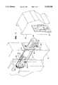
- FIG. 1is a perspective view of the subject invention with the deadbolt in an extended position.
- FIG. 2is a perspective view of the subject invention with the deadbolt in a retracted position.
- FIG. 3is a perspective view of the subject invention with the deadbolt in a partially extended position showing the partial pivoting of the lever.
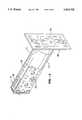
- FIG. 4is an exploded view of the subject invention.
- FIG. 5is a cross-sectional view of the deadbolt assembly, minus the front mounting plate.
- FIGS. 1-5there is shown a preferred embodiment of self-activating spring latch for a sliding door.
- the subject deviceis utilized in connection with a typical sliding door.
- the sliding dooritself is mounted in a pocket frame or equivalent structure that fits within a wall.
- the dooris slid out of the pocket.
- the subject inventionprovides the user with a means for locking the closed door (slid out of pocket) against a strike plate S mounted on the frame.
- the subject apparatuscomprises a housing constructed from a first side plate 5, a second side plate 10, a back plate 15, and a front mounting plate 20.
- the four housing components(5, 10, 15, and 20) cooperate to hold or encase the remaining elements of the subject apparatus.
- Other equivalent configurationsare contemplated to be within the realm of this disclosure and include fabrication designs that incorporate combined or additional similar elements.
- the housingfits within the sliding door D.
- the front mounting plateis secured to the door D by standard means such as screws, bolts, and the like.
- FIG. 1illustrates the deadbolt 25 in an extended and strike plate S engaging position.
- FIG. 2depicts the deadbolt 25 in a retracted and strike plate S nonengaging position.
- FIG. 3depicts the deadbolt 25 in an intermediate or partially extended position.
- FIGS. 4 and 5show a typical structure for the deadbolt 25.
- the deadbolt 25has a first end that enters the strike plate S and a second end that slides within the housing.
- a longitudinal aperture 30is formed in the deadbolt 25 and extends to proximate the deadbolt first end.
- a notch 35utilized in sliding the deadbolt 25 between open and closed positions, is formed proximate the deadbolt second end.
- a deadbolt guide 32fits within the housing to stabilize the sliding of the deadbolt 25 and securing the two halves of the housing 5 and 10 together.
- a lever 40has first and second ends. When assembled, the lever 40 is fitted within the longitudinal aperture 30 and held by pivoting means that permit pivoting such as a pin 45 mounted in a receiving aperture 50 in the deadbolt 25.
- Hooking meansare associated with the lever first end and are utilized for engaging or hooking within or to the strike plate S when the deadbolt 25 is extended.
- the hooking meanscomprises a hook 55 formed proximate the lever first end.
- a critical element of the present inventionis the ability of the device to latch the hook 55 into the strike plate S even if the deadbolt 25 is extended when the sliding door D is closed and the deadbolt 25 inserted into the strike plate S.
- This hooking or latching abilityis provided, in part, by a channel 60 shaped into the lever 40.
- the channel 60extends from proximate the lever second end towards the lever first end.
- a biasing meansthat is typically a spring 65.
- the spring 65fits within the channel 60 and provides a moving pivot point within the channel 60 for the pin 45. If the deadbolt 25 is partially or completely extended when the door is slid shut onto the strike plate S, the hook 55 and associated lever 40 merely compress the spring 65.
- the lever 40pivots into the longitudinal aperture 30. Since the lever 40 and hook 55 are within the longitudinal aperture 30 the deadbolt 25 passes into the strike plate S and the hook 55 snaps out of the longitudinal aperture 30 and behind the strike plate S to secure or latch the sliding door closed.
- Deadbolt extension meansare provided to actuate the sliding of the deadbolt assembly between a nonengaging position and an engaging position for latching the hook 55 with the strike plate S.
- the extension meanscomprises a cam-lever 70 that fits within the deadbolt notch 35.
- the cam-lever 70is pivoted within the housing to slide the deadbolt 25 in and out by rotating with suitable means such as a standard handle attached to the coupling region 75.
- suitable meanssuch as a standard handle attached to the coupling region 75.
- the cam-lever 70is configured to fit within the deadbolt notch 35 and upon appropriate rotation the cam-lever 70 forces the deadbolt 25 out of and into the housing.
- FIGS. 1-3the top of the cam-lever 70 is seen in three positions partially extending above the deadbolt notch 35.
- resilient meansusually a spring 80, is supplied.
- a useremploys the subject device by mounting in a suitable sliding door D.
- the userdoes not need to be concerned about whether or not the deadbolt 25 is extended when the door D is closed onto the strike plate S.
- the deadbolt 25will pass into the receiving strike plate S opening.
- the lever 40 and associated hook 55deflect into the deadbolt longitudinal aperture 30 via the variable pivot point within the lever channel 60.
- the lever 40cooperates with the housing structure to pivot the lever 40 back .into the longitudinal aperture to release the strike plate S.
- a nub 85 on the lever 40catches within a slot 90 in the housing and initiates pivoting of the lever 40 and associated hook 55 into the longitudinal aperture 30.
Landscapes
- Engineering & Computer Science (AREA)
- Structural Engineering (AREA)
- Mechanical Engineering (AREA)
- Securing Of Glass Panes Or The Like (AREA)
Abstract
Description
Claims (8)
Priority Applications (4)
| Application Number | Priority Date | Filing Date | Title |
|---|---|---|---|
| US08/210,694US5452928A (en) | 1994-03-17 | 1994-03-17 | Sliding door self-latching apparatus |
| US08/396,557US5529351A (en) | 1994-03-17 | 1995-03-01 | Sliding door self-latching apparatus |
| US08/585,430US5816629A (en) | 1994-03-17 | 1996-01-11 | Sliding door latch with self-retracting finger pull |
| US09/680,816USRE38693E1 (en) | 1994-03-17 | 2000-10-05 | Sliding door latch with self-retracting finger pull |
Applications Claiming Priority (1)
| Application Number | Priority Date | Filing Date | Title |
|---|---|---|---|
| US08/210,694US5452928A (en) | 1994-03-17 | 1994-03-17 | Sliding door self-latching apparatus |
Related Child Applications (1)
| Application Number | Title | Priority Date | Filing Date |
|---|---|---|---|
| US08/396,557Continuation-In-PartUS5529351A (en) | 1994-03-17 | 1995-03-01 | Sliding door self-latching apparatus |
Publications (1)
| Publication Number | Publication Date |
|---|---|
| US5452928Atrue US5452928A (en) | 1995-09-26 |
Family
ID=22783898
Family Applications (1)
| Application Number | Title | Priority Date | Filing Date |
|---|---|---|---|
| US08/210,694Expired - LifetimeUS5452928A (en) | 1994-03-17 | 1994-03-17 | Sliding door self-latching apparatus |
Country Status (1)
| Country | Link |
|---|---|
| US (1) | US5452928A (en) |
Cited By (19)
| Publication number | Priority date | Publication date | Assignee | Title |
|---|---|---|---|---|
| US5529351A (en)* | 1994-03-17 | 1996-06-25 | Donald; Joseph G. | Sliding door self-latching apparatus |
| US5611581A (en)* | 1995-03-13 | 1997-03-18 | Emhart Inc. | Latch assembly |
| US5676407A (en)* | 1996-06-03 | 1997-10-14 | Schlage Lock Company | Dead bolt actuating assembly |
| US5794991A (en)* | 1996-06-03 | 1998-08-18 | Schlage Lock Company | Interlocking dead bolt with projecting pins |
| US5816629A (en)* | 1994-03-17 | 1998-10-06 | Grodon Lock Inc. | Sliding door latch with self-retracting finger pull |
| US6361087B1 (en)* | 1998-01-09 | 2002-03-26 | Ferco International Ferrures Et Serrures De Batiment Sa | Locking fitting for a door, French window or the like provided with a spring-bolt elastically restored into locking position |
| US6443504B1 (en) | 2000-02-09 | 2002-09-03 | Emhart Llc | Sliding door latch with finger pull lever |
| AU782549B2 (en)* | 2000-02-09 | 2005-08-11 | Allegion (Australia) Pty Ltd | A lock for a sliding door |
| EP1717390A3 (en)* | 2005-04-28 | 2010-01-13 | Lehmann Vertriebsgesellschaft mbH | Dead bolt lock with a striker |
| US7942457B1 (en)* | 2007-04-02 | 2011-05-17 | Donald Bell | Lever-handled pocket door latching system |
| US20120061974A1 (en)* | 2010-09-09 | 2012-03-15 | Laverty Edward T | Cavity door end pull latch set and lock set |
| EP2525027A2 (en) | 2011-05-18 | 2012-11-21 | Jacou Industry Zhongshan Limited | Privacy latch |
| WO2016024274A3 (en)* | 2014-08-12 | 2016-04-21 | Rav Bariach (08) Industries Ltd. | Fortified deadbolt latch |
| DE202015102261U1 (en)* | 2015-05-04 | 2016-08-08 | Burg-Wächter Kg | Device for receiving consignments, door unit and locking system |
| CN107100455A (en)* | 2017-04-27 | 2017-08-29 | 程倩雁 | Sliding door door lock |
| US20220064998A9 (en)* | 2019-08-17 | 2022-03-03 | Travis Brett Creighton | Securable deadbolt, hinge , and sliding assemblies |
| FR3139590A1 (en)* | 2022-09-08 | 2024-03-15 | F.T.F.M. La Toulousaine | Sectional door with manual lateral movement incorporating a gate and a closing/locking system on the discharge side |
| US11965363B2 (en)* | 2018-03-31 | 2024-04-23 | Triangle Brass Manufacturing Co., Inc. | Barn door handle assembly, strike assembly, and lock system |
| USD1026613S1 (en)* | 2017-01-19 | 2024-05-14 | Endura Products, Llc | Locking device |
Citations (6)
| Publication number | Priority date | Publication date | Assignee | Title |
|---|---|---|---|---|
| US195270A (en)* | 1877-09-18 | Improvement in reversible latches | ||
| US205041A (en)* | 1878-06-18 | Improvement in latches | ||
| US2230096A (en)* | 1940-01-08 | 1941-01-28 | Sargent & Co | Door latch |
| US2793894A (en)* | 1954-12-31 | 1957-05-28 | Edward S Modes | Door latch |
| US3600021A (en)* | 1969-09-15 | 1971-08-17 | Minnesota Mining & Mfg | Lock structure |
| US4566725A (en)* | 1984-01-30 | 1986-01-28 | Almet Hardware Limited | Deadlock mechanism |
- 1994
- 1994-03-17USUS08/210,694patent/US5452928A/ennot_activeExpired - Lifetime
Patent Citations (6)
| Publication number | Priority date | Publication date | Assignee | Title |
|---|---|---|---|---|
| US195270A (en)* | 1877-09-18 | Improvement in reversible latches | ||
| US205041A (en)* | 1878-06-18 | Improvement in latches | ||
| US2230096A (en)* | 1940-01-08 | 1941-01-28 | Sargent & Co | Door latch |
| US2793894A (en)* | 1954-12-31 | 1957-05-28 | Edward S Modes | Door latch |
| US3600021A (en)* | 1969-09-15 | 1971-08-17 | Minnesota Mining & Mfg | Lock structure |
| US4566725A (en)* | 1984-01-30 | 1986-01-28 | Almet Hardware Limited | Deadlock mechanism |
Cited By (30)
| Publication number | Priority date | Publication date | Assignee | Title |
|---|---|---|---|---|
| USRE38693E1 (en)* | 1994-03-17 | 2005-02-01 | Newfrey Llc | Sliding door latch with self-retracting finger pull |
| US5816629A (en)* | 1994-03-17 | 1998-10-06 | Grodon Lock Inc. | Sliding door latch with self-retracting finger pull |
| US5529351A (en)* | 1994-03-17 | 1996-06-25 | Donald; Joseph G. | Sliding door self-latching apparatus |
| US5611581A (en)* | 1995-03-13 | 1997-03-18 | Emhart Inc. | Latch assembly |
| ES2144894A1 (en)* | 1995-03-13 | 2000-06-16 | Emhart Inc | Latch assembly |
| US5676407A (en)* | 1996-06-03 | 1997-10-14 | Schlage Lock Company | Dead bolt actuating assembly |
| US5794991A (en)* | 1996-06-03 | 1998-08-18 | Schlage Lock Company | Interlocking dead bolt with projecting pins |
| US6361087B1 (en)* | 1998-01-09 | 2002-03-26 | Ferco International Ferrures Et Serrures De Batiment Sa | Locking fitting for a door, French window or the like provided with a spring-bolt elastically restored into locking position |
| US6443504B1 (en) | 2000-02-09 | 2002-09-03 | Emhart Llc | Sliding door latch with finger pull lever |
| AU782549B2 (en)* | 2000-02-09 | 2005-08-11 | Allegion (Australia) Pty Ltd | A lock for a sliding door |
| EP1717390A3 (en)* | 2005-04-28 | 2010-01-13 | Lehmann Vertriebsgesellschaft mbH | Dead bolt lock with a striker |
| DE102005020194B4 (en)* | 2005-04-28 | 2017-08-31 | Lehmann Vertriebsgesellschaft Mbh | Arrangement of a bolt lock with a closure counterpart on a furniture door |
| US7942457B1 (en)* | 2007-04-02 | 2011-05-17 | Donald Bell | Lever-handled pocket door latching system |
| US20120061974A1 (en)* | 2010-09-09 | 2012-03-15 | Laverty Edward T | Cavity door end pull latch set and lock set |
| US9151080B2 (en) | 2011-05-18 | 2015-10-06 | Jacou Industry Zhongshan Limited | Privacy latch |
| EP2525027A2 (en) | 2011-05-18 | 2012-11-21 | Jacou Industry Zhongshan Limited | Privacy latch |
| US20170226776A1 (en)* | 2014-08-12 | 2017-08-10 | Rav Bariach (08) Industries Ltd | Fortified Deadbolt Latch |
| US10837201B2 (en)* | 2014-08-12 | 2020-11-17 | Rav Bariach (08) Industries Ltd. | Fortified deadbolt latch |
| WO2016024274A3 (en)* | 2014-08-12 | 2016-04-21 | Rav Bariach (08) Industries Ltd. | Fortified deadbolt latch |
| DE202015102261U1 (en)* | 2015-05-04 | 2016-08-08 | Burg-Wächter Kg | Device for receiving consignments, door unit and locking system |
| US12146344B2 (en) | 2017-01-19 | 2024-11-19 | Endura Products, Llc | Multipoint lock |
| US12104409B2 (en) | 2017-01-19 | 2024-10-01 | Endura Products, Llc | Multipoint lock |
| USD1026613S1 (en)* | 2017-01-19 | 2024-05-14 | Endura Products, Llc | Locking device |
| CN107100455A (en)* | 2017-04-27 | 2017-08-29 | 程倩雁 | Sliding door door lock |
| CN107100455B (en)* | 2017-04-27 | 2022-06-21 | 程倩雁 | Door lock for sliding door |
| US11965363B2 (en)* | 2018-03-31 | 2024-04-23 | Triangle Brass Manufacturing Co., Inc. | Barn door handle assembly, strike assembly, and lock system |
| US20220064998A9 (en)* | 2019-08-17 | 2022-03-03 | Travis Brett Creighton | Securable deadbolt, hinge , and sliding assemblies |
| US11598119B2 (en)* | 2019-08-17 | 2023-03-07 | Travis Brett Creighton | Securable deadbolt, hinge, and sliding assemblies |
| US20230203840A1 (en)* | 2020-05-14 | 2023-06-29 | Travis Brett Creighton | Securable deadbolt, hinge, and sliding assemblies |
| FR3139590A1 (en)* | 2022-09-08 | 2024-03-15 | F.T.F.M. La Toulousaine | Sectional door with manual lateral movement incorporating a gate and a closing/locking system on the discharge side |
Similar Documents
| Publication | Publication Date | Title |
|---|---|---|
| US5452928A (en) | Sliding door self-latching apparatus | |
| US4693503A (en) | Lever latch | |
| US4438964A (en) | Paddle operated vehicle latch | |
| US5529351A (en) | Sliding door self-latching apparatus | |
| US5901501A (en) | Window fastener | |
| US5090754A (en) | Restrictor device with a releasable latch member | |
| US4676081A (en) | Snap-in semi-flush mounted panel lock | |
| US5516162A (en) | Hook-bolt lock assembly | |
| US5816629A (en) | Sliding door latch with self-retracting finger pull | |
| US5865480A (en) | Sliding door security and child safety latch | |
| US6009932A (en) | Push to exit, pull to enter latch assembly for screen door | |
| CA2161041C (en) | Pocket door latch | |
| US3439948A (en) | Door latch assembly | |
| US4031725A (en) | Door lock | |
| JPH10151254A (en) | Locking device for pachinko machine | |
| JPH0332213Y2 (en) | ||
| WO1999050517A1 (en) | Door lock | |
| US3401968A (en) | Cam actuated latch | |
| US6419287B1 (en) | Fastening mechanism for a cover, door or the like | |
| JP4195127B2 (en) | Door lock | |
| US4784416A (en) | Door latch | |
| US5106131A (en) | Self-closing gate latch | |
| JPH0339585Y2 (en) | ||
| JP2533391Y2 (en) | Locking device | |
| US3811301A (en) | Multiple purpose latch mechanism |
Legal Events
| Date | Code | Title | Description |
|---|---|---|---|
| STCF | Information on status: patent grant | Free format text:PATENTED CASE | |
| AS | Assignment | Owner name:GRODON LOCK INC., CALIFORNIA Free format text:ASSIGNMENT OF ASSIGNORS INTEREST;ASSIGNOR:DONALD, JOSEPH G.;REEL/FRAME:007908/0279 Effective date:19960411 | |
| REMI | Maintenance fee reminder mailed | ||
| FPAY | Fee payment | Year of fee payment:4 | |
| SULP | Surcharge for late payment | ||
| AS | Assignment | Owner name:DONALD, JOSEPH G., CALIFORNIA Free format text:ASSIGNMENT OF ASSIGNORS INTEREST;ASSIGNOR:GROTON LOCK, INC.;REEL/FRAME:010977/0733 Effective date:20000223 | |
| AS | Assignment | Owner name:EMHART INC., DELAWARE Free format text:ASSIGNMENT OF ASSIGNORS INTEREST;ASSIGNOR:DONALD, JOSEPH G.;REEL/FRAME:011333/0431 Effective date:20001005 | |
| AS | Assignment | Owner name:EMHART LLC, DELAWARE Free format text:CHANGE OF NAME - CONVERSION TO LLC;ASSIGNOR:EMHART INC.;REEL/FRAME:012967/0624 Effective date:20011029 | |
| FEPP | Fee payment procedure | Free format text:PAYOR NUMBER ASSIGNED (ORIGINAL EVENT CODE: ASPN); ENTITY STATUS OF PATENT OWNER: LARGE ENTITY | |
| FEPP | Fee payment procedure | Free format text:PAT HOLDER NO LONGER CLAIMS SMALL ENTITY STATUS, ENTITY STATUS SET TO UNDISCOUNTED (ORIGINAL EVENT CODE: STOL); ENTITY STATUS OF PATENT OWNER: LARGE ENTITY | |
| REFU | Refund | Free format text:REFUND - PAYMENT OF MAINTENANCE FEE, 8TH YR, SMALL ENTITY (ORIGINAL EVENT CODE: R2552); ENTITY STATUS OF PATENT OWNER: LARGE ENTITY | |
| AS | Assignment | Owner name:NEWFREY LLC, DELAWARE Free format text:CHANGE OF NAME;ASSIGNOR:EMHART LLC;REEL/FRAME:013678/0528 Effective date:20021030 | |
| FPAY | Fee payment | Year of fee payment:8 | |
| FPAY | Fee payment | Year of fee payment:12 | |
| AS | Assignment | Owner name:SPECTRUM BRANDS, INC., WISCONSIN Free format text:ASSIGNMENT OF ASSIGNORS INTEREST;ASSIGNOR:NEWFREY LLC;REEL/FRAME:029510/0820 Effective date:20121217 | |
| AS | Assignment | Owner name:KWIKSET CORPORATION, CALIFORNIA Free format text:PATENT ASSIGNMENT AGREEMENT;ASSIGNOR:SPECTRUM BRANDS, INC.;REEL/FRAME:029537/0001 Effective date:20121217 Owner name:WELLS FARGO BANK, NATIONAL ASSOCIATION, GEORGIA Free format text:PATENT SECURITY AGREEMENT;ASSIGNORS:PRICE PFISTER, INC.;KWIKSET CORPORATION;NATIONAL MANUFACTURING CO.;REEL/FRAME:029538/0186 Effective date:20121217 | |
| AS | Assignment | Owner name:BANK OF AMERICA, N.A., AS AGENT, CONNECTICUT Free format text:SECURITY AGREEMENT;ASSIGNORS:PRICE PFISTER, INC.;KWIKSET CORPORATION;NATIONAL MANUFACTURING CO.;REEL/FRAME:029731/0589 Effective date:20121217 | |
| AS | Assignment | Owner name:APPLICA CONSUMER PRODUCTS, INC., FLORIDA Free format text:RELEASE BY SECURED PARTY;ASSIGNOR:BANK OF AMERICA, N.A., AS AGENT;REEL/FRAME:036052/0845 Effective date:20150623 Owner name:TETRA HOLDING (US), INC., WISCONSIN Free format text:RELEASE BY SECURED PARTY;ASSIGNOR:BANK OF AMERICA, N.A., AS AGENT;REEL/FRAME:036052/0845 Effective date:20150623 Owner name:TOASTMASTER INC., FLORIDA Free format text:RELEASE BY SECURED PARTY;ASSIGNOR:BANK OF AMERICA, N.A., AS AGENT;REEL/FRAME:036052/0845 Effective date:20150623 Owner name:TELL MANUFACTURING, INC., PENNSYLVANIA Free format text:RELEASE BY SECURED PARTY;ASSIGNOR:BANK OF AMERICA, N.A., AS AGENT;REEL/FRAME:036052/0845 Effective date:20150623 Owner name:RUSSELL HOBBS, INC., FLORIDA Free format text:RELEASE BY SECURED PARTY;ASSIGNOR:BANK OF AMERICA, N.A., AS AGENT;REEL/FRAME:036052/0845 Effective date:20150623 Owner name:NATIONAL MANUFACTURING CO., CALIFORNIA Free format text:RELEASE BY SECURED PARTY;ASSIGNOR:BANK OF AMERICA, N.A., AS AGENT;REEL/FRAME:036052/0845 Effective date:20150623 Owner name:KWIKSET CORPORATION, CALIFORNIA Free format text:RELEASE BY SECURED PARTY;ASSIGNOR:BANK OF AMERICA, N.A., AS AGENT;REEL/FRAME:036052/0845 Effective date:20150623 Owner name:UNITED PET GROUP, INC., WISCONSIN Free format text:RELEASE BY SECURED PARTY;ASSIGNOR:BANK OF AMERICA, N.A., AS AGENT;REEL/FRAME:036052/0845 Effective date:20150623 Owner name:PRICE PFISTER, INC., CALIFORNIA Free format text:RELEASE BY SECURED PARTY;ASSIGNOR:BANK OF AMERICA, N.A., AS AGENT;REEL/FRAME:036052/0845 Effective date:20150623 Owner name:SEED RESOURCES, L.L.C., MICHIGAN Free format text:RELEASE BY SECURED PARTY;ASSIGNOR:BANK OF AMERICA, N.A., AS AGENT;REEL/FRAME:036052/0845 Effective date:20150623 Owner name:LIQUID HOLDING COMPANY, INC., PENNSYLVANIA Free format text:RELEASE BY SECURED PARTY;ASSIGNOR:BANK OF AMERICA, N.A., AS AGENT;REEL/FRAME:036052/0845 Effective date:20150623 Owner name:SPECTRUM BRANDS, INC., WISCONSIN Free format text:RELEASE BY SECURED PARTY;ASSIGNOR:BANK OF AMERICA, N.A., AS AGENT;REEL/FRAME:036052/0845 Effective date:20150623 Owner name:ROVCAL, INC., WISCONSIN Free format text:RELEASE BY SECURED PARTY;ASSIGNOR:BANK OF AMERICA, N.A., AS AGENT;REEL/FRAME:036052/0845 Effective date:20150623 Owner name:SALIX ANIMAL HEALTH, LLC, FLORIDA Free format text:RELEASE BY SECURED PARTY;ASSIGNOR:BANK OF AMERICA, N.A., AS AGENT;REEL/FRAME:036052/0845 Effective date:20150623 |