US5452480A - Ski goggles - Google Patents
Ski gogglesDownload PDFInfo
- Publication number
- US5452480A US5452480AUS08/227,451US22745194AUS5452480AUS 5452480 AUS5452480 AUS 5452480AUS 22745194 AUS22745194 AUS 22745194AUS 5452480 AUS5452480 AUS 5452480A
- Authority
- US
- United States
- Prior art keywords
- frame member
- goggle
- air
- fan blade
- user
- Prior art date
- Legal status (The legal status is an assumption and is not a legal conclusion. Google has not performed a legal analysis and makes no representation as to the accuracy of the status listed.)
- Expired - Lifetime
Links
- 238000009423ventilationMethods0.000claimsabstractdescription32
- 230000000712assemblyEffects0.000claimsdescription3
- 238000000429assemblyMethods0.000claimsdescription3
- 239000003570airSubstances0.000claims45
- 239000012080ambient airSubstances0.000claims6
- 230000001154acute effectEffects0.000claims1
- 210000005069earsAnatomy0.000claims1
- 210000001747pupilAnatomy0.000claims1
- 238000000034methodMethods0.000abstractdescription25
- 238000013461designMethods0.000abstractdescription8
- 230000005494condensationEffects0.000abstract1
- 238000009833condensationMethods0.000abstract1
- XLYOFNOQVPJJNP-UHFFFAOYSA-NwaterChemical compoundOXLYOFNOQVPJJNP-UHFFFAOYSA-N0.000description19
- 230000000694effectsEffects0.000description18
- 238000012360testing methodMethods0.000description10
- 238000005259measurementMethods0.000description9
- 230000002265preventionEffects0.000description7
- 230000007423decreaseEffects0.000description5
- 239000006260foamSubstances0.000description5
- 210000003128headAnatomy0.000description5
- 230000001965increasing effectEffects0.000description4
- 230000007246mechanismEffects0.000description4
- 230000009467reductionEffects0.000description4
- 101150091813shfl geneProteins0.000description4
- 238000013459approachMethods0.000description3
- 230000008859changeEffects0.000description3
- 230000001419dependent effectEffects0.000description3
- 230000008030eliminationEffects0.000description3
- 238000003379elimination reactionMethods0.000description3
- 238000010438heat treatmentMethods0.000description3
- 238000010998test methodMethods0.000description3
- 238000009825accumulationMethods0.000description2
- 230000008901benefitEffects0.000description2
- 230000015572biosynthetic processEffects0.000description2
- 230000003993interactionEffects0.000description2
- 238000012986modificationMethods0.000description2
- 230000004048modificationEffects0.000description2
- 210000004279orbitAnatomy0.000description2
- 239000000523sampleSubstances0.000description2
- 241000272517AnseriformesSpecies0.000description1
- 230000004075alterationEffects0.000description1
- 230000009286beneficial effectEffects0.000description1
- 230000003247decreasing effectEffects0.000description1
- 230000007812deficiencyEffects0.000description1
- 230000009977dual effectEffects0.000description1
- 230000002708enhancing effectEffects0.000description1
- 238000011156evaluationMethods0.000description1
- 230000007717exclusionEffects0.000description1
- 239000006261foam materialSubstances0.000description1
- 238000003780insertionMethods0.000description1
- 230000037431insertionEffects0.000description1
- 238000012886linear functionMethods0.000description1
- 238000012423maintenanceMethods0.000description1
- 239000000463materialSubstances0.000description1
- 230000002085persistent effectEffects0.000description1
- 230000001681protective effectEffects0.000description1
- 238000012887quadratic functionMethods0.000description1
- 230000005855radiationEffects0.000description1
- 230000004044responseEffects0.000description1
- 230000002441reversible effectEffects0.000description1
- 238000005070samplingMethods0.000description1
- 238000000926separation methodMethods0.000description1
- 238000006467substitution reactionMethods0.000description1
- 230000000007visual effectEffects0.000description1
- 238000004804windingMethods0.000description1
- 210000000216zygomaAnatomy0.000description1
Images


Classifications
- G—PHYSICS
- G02—OPTICS
- G02C—SPECTACLES; SUNGLASSES OR GOGGLES INSOFAR AS THEY HAVE THE SAME FEATURES AS SPECTACLES; CONTACT LENSES
- G02C11/00—Non-optical adjuncts; Attachment thereof
- G02C11/08—Anti-misting means, e.g. ventilating, heating; Wipers
- A—HUMAN NECESSITIES
- A61—MEDICAL OR VETERINARY SCIENCE; HYGIENE
- A61F—FILTERS IMPLANTABLE INTO BLOOD VESSELS; PROSTHESES; DEVICES PROVIDING PATENCY TO, OR PREVENTING COLLAPSING OF, TUBULAR STRUCTURES OF THE BODY, e.g. STENTS; ORTHOPAEDIC, NURSING OR CONTRACEPTIVE DEVICES; FOMENTATION; TREATMENT OR PROTECTION OF EYES OR EARS; BANDAGES, DRESSINGS OR ABSORBENT PADS; FIRST-AID KITS
- A61F9/00—Methods or devices for treatment of the eyes; Devices for putting in contact-lenses; Devices to correct squinting; Apparatus to guide the blind; Protective devices for the eyes, carried on the body or in the hand
- A61F9/02—Goggles
- A61F9/028—Ventilation means
Definitions
- This inventionrelates to an improved ski goggle which is comfortable to wear, prevents goggle lens fogging, prevents lens fogging of eyeglasses worn under the goggle, and avoids audible noises from a fan used to prevent lens fogging.
- Modern ski gogglesattempt to achieve a number of design goals dictated by operation in a harsh winter environment. These design goals include attenuation of bright outside visible light, elimination of ultraviolet solar radiation, maximizing visual recognition of snow pack features in both high and low light levels, prevention of goggle lens fogging, prevention of fogging of eyeglasses worn under a goggle, and exclusion of various other outside harsh weather environments. These goals need to be achieved via means which do not generally impede motion of a skier, which do not detract from positive aspects of the skiing environment, and which can be offered commercially at reasonable prices.
- Modern ski gogglesas are widely available commercially and as are further described in the prior art (see U.S. Pat. Nos. 3,377,626 to Smith and 4,150,443 to McNeilly) employ a design compromise characterized by over ventilation when a skier is in motion and under ventilation when the skier is at rest. This over ventilation results in uncomfortable wind chill effects on the skier's face and eyes, rapid temperature decrease of goggle and eyeglass lenses, and lens fogging when the skier's exhaled breath enters the goggle air space.
- under ventilationcauses the dew point of the goggle air space to rise rapidly via expiration of water vapor from the skier's eyes, and intake of skier's exhaled breath. This elevated dew point, if it exceeds the decreased lens temperature, results in lens fogging.
- U.S. Pat. No. 2,526,737 to Farinadiscloses the use of a breath powered exhaust fan; Smith discloses an insulated goggle lens; McNeilly and U.S. Pat. No. 3,825,953 to Hunter disclose the use of an electric fan; U.S. Pat. No. 4,868,929 to Curcio discloses an electrically heated goggle lens; U.S. Ser. No. 07/947,740, filed by Ryden, the applicant herein, discloses electrically heated eyeglasses.
- Farinadiscloses use of exhaust fans to remove moist air from the goggle space in front of the eyes.
- the shaft of this fanis shared with a turbine which is made to rotate by constraining the exhaled skier's breath to flow through the turbine and thereby rotate the fan shaft.
- This fan meansis quite inconvenient to use on a continuous basis and is also impractical for operation at predetermined fan speeds.
- Farinadoes not address the use of eyeglasses under a goggle.
- Smithdiscloses a multi-component lens goggle to increase the temperature of the innermost lens. This practice reduces goggle lens fogging, but is ineffective in preventing fogging of an eyeglass worn under a goggle. Smith also discloses an improved ski goggle that uses an air permeable goggle frame, so that the goggle air space is in slow but controlled air exchange with the outside air, thereby keeping the air inside the goggle and the skier's face warm but also preventing moisture accumulation. It is readily understood that such an air permeable frame may be advantageous over an open frame, such as that of an eyeglass; and advantageous over a closed frame that would allow moisture accumulation. Such an air permeable frame shows significant goggle air space temperature variation depending on the rate of skier motion. Use of an eyeglass under such a goggle will result in eyeglass lens fogging due to this temperature variation and intake of exhaled skier breath through the air permeable frame.
- McNeilly and Hunterare both effective at preventing goggle fogging and McNeilly specifically discloses features intended to defog an eyeglass worn under a goggle.
- McNeillyrelies on open goggle ventilation as disclosed by Smith for effective defogging of the McNeilly goggle. Consequently, McNeilly suffers from the over ventilation problem discussed above.
- the electric fans used in both McNeilly and Hunterproduce sound levels which are very annoying to the skier and, consequently, in practice, the fans are only operated to defog lenses as opposed to preventing fogging from occurring. This annoying sound level (estimated at 35 decibels) is due to the high fan blade rotational speed required to produce the desired defogging effect when using small fans of the type appropriate for mounting on or near a goggle.
- An object of this inventionis to provide a generally improved ski goggle which can be used in winter sports without fogging the lenses of the goggle or the lenses of eyeglasses worn under the goggle.
- Another object of this inventionis to provide such an improved goggle which continuously uses an electric fan to prevent fogging, without creating distracting noise.
- Yet another object of this inventionis to provide such an improved goggle with a fog prevention mechanism which is self-contained on the goggle and operable for at least a full day of winter sports activity without intervention by the goggle wearer.
- a still further object of this inventionis to provide a uniform level of comfort to a skier's face and eyes, irrespective of whether the skier is in rapid motion, while the goggle is worn.
- the improved ski goggle disclosed hererelies on a new method of electric fan operation to prevent goggle fogging.
- This new fan operation methodallows for continuous and silent fan operation.
- Use of the fan, as disclosed herealso advantageously allows use of a much restricted goggle ventilation design, thereby resulting in higher goggle air space temperatures and reduced wind chill effects when the skier is in motion.
- This new fan operation methodconsumes 1/10 to 1/100 the electrical power of heated eyeglasses, and thereby allows needed batteries to be self-contained on a goggle.
- This method of preventing lens foggingis generally understood from an examination of the causes of goggle lens fogging and of eyeglass lens fogging when such eyeglass is worn under a goggle (referred to herein as a "related eyeglass"), and detailed measurements presented herein.
- Any surfacewill accumulate water vapor when the temperature of the surface is lower than the dew point temperature of the adjacent air.
- lens temperature and dew pointare both subject to frequent change which may result in lens fogging.
- Two sources of water vaporincrease the goggle air space dew point temperature (the "Dew Point") above that generally prevailing in the skier's absence: the skier's face, including the eyes, tears therefrom, and skin; and the exhaled breath of the skier. Ventilation of the goggle air space by rapid skier motion causes lens temperatures to fall.
- the invention disclosed hereineliminates water vapor produced inside the goggle air space by using a new goggle ventilation technique which is understood based on data reported here and obtained using an electronic instrument (Fisher Scientific digital hygrometer/thermometer, catalog number 11-661-7B) which measures air temperature, and air water vapor content (given as dew point and relative humidity).
- the water vapor sensor of this instrumentis capable of fast response time (2 seconds) and is small enough that it can be placed in the air space between the eye and an eyeglass.
- the temperature and water vapor content measurements of this instrumenthave a calibration traceable to the National Institute of Standards and Tests.
- Goggle and eyeglass lens temperatureshave been measured for tests reported herein using a digital thermometer with two thermocouple probes (Simpson, Model 383).
- Table 1summarizes test results conducted during the design of the improved goggle claimed herein.
- Table 1gives the time in seconds for the relative humidity within a small fan ventilated inclosure to change from a value of 100% to 60%.
- This inclosurehas an air volume roughly equivalent to that of a ski goggle and has various access ports to accommodate introduction of water vapor, mounting of ventilation fans, outside air access, and insertion of various measurement probes.
- the data of Table 1was obtained with a water vapor source (water) having an exposed circular area of 2.5 centimeters diameter and 130° F. temperature.
- Data for two types of fan ventilation configurationsare shown, one being in accordance with McNeilly and the other being direct air exhaust.
- the datais shown as a function of fan volumetric capacity, measured in cubic feet per minute (CFM).
- the data of Table 1suggests that direct air exhaust is more effective at fog prevention and removal than the air circulation technique of McNeilly. This is confirmed using a test described below in which an operative example of McNeilly and a
- Another test procedure employed in developing the invention claimed hereinis to observe fogging of related eyeglasses using various goggle embodiments under closely controlled conditions.
- the related eyeglassis slowly cooled in a refrigerated chamber to 12° F. above the ambient dew point.
- the cooled eyeglassis then positioned normally over the eyes, and the experimental goggle embodiment is placed over the related eyeglass.
- This latter procedureis carried out at about 70° .F, with ambient dew point at 30° F. ⁇ 5° F.
- Fogging of the related eyeglass lensesis then observed, either to determine the ability of the experimental goggle embodiment to prevent related eyeglass fogging or, if the related eyeglass is allowed to fog, to determine the ability of the experimental goggle to clear fogging.
- McNeillyAn operative embodiment of McNeilly is available commercially from Smith Sport Optics, Inc., and is referred to herein as the "Smith Fan Goggle".
- the fan of this gogglehas an annoying sound level, estimated at 35 decibels (db), which is largely attributable to sound produced by fan blade rotation of 17,000 RPM. This sound level could be reduced significantly by use of lower fan RPM, but such reduction results in a reduction of fan volumetric capacity.
- the Smith Fan Gogglebecomes ineffective at either preventing lens fogging or defogging lenses. This is illustrated in the data of Table 2, where results of the Fogging Test (described in the paragraph above) for the Smith Fan Goggle are presented. The time (in seconds) to clear both related eyeglass lenses, and whether fan operation prevented fogging are indicated.
- the defogging performance of the Smith Fan Goggle at 0.93 CFMis marginal and becomes ineffective at 0.62 CFM.
- the motor type used in the Smith Fan Goggleis loud at any motor speed, but use of appropriate fan motors will not produce quiet operation at the fan capacities required for McNeilly to be effective.
- direct exhausthas proven more effective than circulation for dehumidifying, I reversed the direction of rotation of the motor of the Smith Fan Goggle and provided direct access of the fan exhaust to outside of the goggle. This direct exhaust gives superior performance to that of the Smith Fan Goggle as seen by comparing the defogging results for these two goggles given in Table 2. However, it is seen from the results of Table 2 that this method of defogging becomes ineffective at fan capacities below 0.5 CFM.
- the Uvex and Swan commercial fan gogglesalso exhibit annoying sound levels similar to the Smith Fan Goggle.
- the former gogglesoperate in the direct exhaust mode.
- the Swan gogglehas the additional feature that the fan can be turned on or off by a mechanism which is controlled by a sensor of relative humidity level within the goggle.
- a key feature of the invention disclosed hereinis that the ventilation technique disclosed achieves fog-free lenses with reduced fan blade rotational speed, thereby resulting in inaudible fan blade sound emission levels.
- one embodiment of this inventionusing a fan of similar physical size to that used in the Smith Fan Goggle, can operate at 3000 RPM (0.3 CFM) and be inaudible and effective in defogging a related eyeglass. Results of the Fogging Test on this embodiment of the present invention show fog clearing in 45 seconds. Moreover, fogging is prevented while the inaudible fan is in use.
- the present inventionutilizes goggle air replacement rates slightly higher than that needed to effect the above described sudden drop in dew point temperature. Air replacement rates higher or lower than this are less desirable. Higher rates, although effective at fog prevention as indicated by the data of Table 2, lower the goggle internal temperature, making the goggle less comfortable, and produce wind chill effects and sound levels that are annoying to the skier. Lower rates, although generally capable of fog-free performance, may result in occasional fogging which may persist.
- a major cause of air flow nonuniformityis the interaction between the circularly symmetric air flow pattern of an isolated fan and the restrictive boundaries of the goggle and related eyeglass.
- this interactionresults in air flow from one side of the goggle being drawn into the forward side of the fan, while air from the other side of the goggle is drawn into the rear side of the fan.
- This asymmetric air flowcauses the right and left air spaces behind the lenses of a related eyeglass to be exhausted at different rates.
- This nonuniform air flowcan be counteracted by suitable asymmetric placement, modification, or orientation of the fan.
- movement of the fan laterally to one side of the goggle centeris effective in equalizing the air flow behind each related eyeglass lens.
- Another technique which has been found to be effective in this regardis rotation of the fan axis by about 45 degrees about a second axis which passes through the fan from right to left.
- Electric motors of the type used in presently available commercial fan gogglesare inexpensive, but generate considerable sound levels from armature winding electrical contacts (brushes), even at low fan RPM. This noise source can be minimized in more expensive versions of this motor type, but not eliminated.
- Two types of brushless fansare widely available. The first type uses electronic commutators and the second type uses electronic generation of three phase drive voltages and a brushless three phase ac motor.
- a significant advantage of the fan forced ventilation technique used in the present inventionis that the size of ventilation ports along the goggle frame can be significantly reduced. Elimination of all ports in the top of the goggle frame except the fan exhaust is particularly advantageous. Small ports in the frame bottom near the cheek bone allow good air flow when related eyeglasses are worn. These ports, however, may allow exhaled breath to enter the goggle and cause brief fogging. When the instant fan forced defogging method is utilized, these bottom ports can also be eliminated. In this case, the two frame ports used to allow passage of eyeglass temple pieces through the goggle frame are relied on as the only air intake ports. The temple ports allow excellent air flow into the goggle along the face where good access is afforded to the space between and eyeglass lens and the eye socket.
- the improved goggle ventilation techniques disclosed hereincan advantageously use various electronic means to obtain a high level of power use efficiency.
- One such electronic techniqueis pulse width modulation, in which drive voltage is only applied to the motor for a fraction of a repeating duty cycle. In this way variable fan speed is obtainable from a fixed battery voltage with nearly 100% power efficiency.
- Another embodiment of the invention described hereinadvantageously uses electronic fan controls and both temperature sensors and water vapor sensors to effect a predetermined difference between the goggle or related eyeglass lens temperature and the Dew Point. That temperature difference can be minimized in this situation compared to one in which only manual fan controls are used. Placement of the sensors near the fan intake would allow effective sampling of inside air space conditions.
- the sensorscould be mounted on the goggle frame or the fan assembly, or mounted on extensions attached at one end to either the frame or the fan assembly and extending into the area where temperature or water vapor measurement is desired.
- fan speedcould be automatically increased to lower the Dew Point. Such fan operation could significantly lower the power needed to drive the fan while still providing fog-free operation.
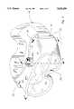
- FIG. 1is a perspective view of a goggle according this invention, depicted on the head of a user.
- FIG. 2is a graph of data obtained using an embodiment of this invention in which optimum fan operation range is indicated.
- FIG. 3is a perspective view of the goggle of this invention.
- FIG. 4is a horizontal cross-sectional view of the goggle of this invention, at the level of the top of a related eyeglass, taken generally in the plane of line 4--4 of FIG. 3.
- FIG. 5is a mid-cross sectional view of an embodiment of this invention, taken generally in the plane of line 5--5 of FIG. 3.
- FIG. 6is an end view of the side of the frame and temple port of an embodiment of this invention.
- FIG. 7is a horizontal cross-section view of the goggle of this invention, taken generally in the plane of line 4--4 of FIG. 3, showing an embodiment utilizing dual fans.
- FIG. 1The general operation and appearance of an improved ski goggle according to the present invention can best be understood by reference to FIG. 1.
- This improved goggle 10is comprised of the following structural elements: lens 12, frame 13, and strap 14.
- Goggle lens 12is held in place in front of the wearer's eyes 17 by frame 13.
- the spacing of lens 12 away from face 16allows related eyeglass 23 to be worn with goggle 10.
- Frame 13is comfortably held in place against the wearer's head 15 by use of strap 14, which may advantageously be made of elastic or other flexible material.
- Goggle air space 21has access to air outside the above boundaries through frame ports 22 and exhaust fan 11.
- fan 11exhausts air from within the goggle air space 21 directly to the outside of the goggle 10, with exhausted air being replaced by outside air 26 entering the goggle air space 21 through the frame ports 22. It is generally intended that this fan forced ventilation by outside air will reduce the dew point temperature of the goggle air space 21, thereby preventing fogging of the goggle lens 12.
- a primary feature of the present inventionis the specification of fan operation to minimize fogging of related eyeglass lenses 24,25 while also minimizing fan induced sound and wind chill effects.
- Two temperaturesare found to be important in this regard.
- the first temperatureis the dew point temperature of that portion of goggle air space 21 between lenses 24 or 25 and face 16. This first temperature is referred to herein as dew point T1.
- the second temperatureis the respective temperature of lens 24 or 25. This second temperature is referred to herein as lens temperature T2.
- dew point T1 and lens temperature T2in an embodiment of the present invention as illustrated in FIG. 1, is shown in FIG. 2 as a function of fan volumetric capacity measured in cubic feet per minute (CFM).
- the measurements of dew point T1were obtained with the digital hygrometer/thermometer referenced in section 2.1.
- the measurements of lens temperature T2were obtained with the digital thermocouple thermometer also identified in section 2.1.
- Measurements of dew point T1were obtained with the dew point of outside air 26 at 30° F.
- Measurements of lens temperature T2were obtained with the temperature of outside air 26 at 25° F.
- Dew point T1is seen to fall rapidly at low fan capacity (i.e., less than 0.5 CFM) and then slowly approach the dew point of outside air 26.
- Lens temperature T2shows a uniform, but slower decrease.
- Eyeglass lenses 24, 25will fog only if dew point T1 equals or exceeds respective lens temperature T2.
- dew point T1is not shown to exceed lens temperature T2.
- dew point T1would rise to the temperature (not shown) of the air space between the face 16 and related eyeglass lens 24,25. This temperature is usually above lens temperature T2. Therefore, lens 24 or 25 may fog if adequate water vapor were present in goggle space 21 to cause the necessary rise in dew point T1.
- Ventilation at low fan capacityis seen to result in a significant drop in dew point T1 to a point well below lens temperature T2. This large difference between lens temperature T2 and dew point T1 allows related eyeglass lens 24,25 to remain clear during events which would otherwise have caused lenses 24,25 to fog without fan operation.
- the effects of operation of fan 11 at various volumetric capacitiesis further described below.
- a fan 11may be equipped with a motor control means (not shown) for controlling the fan motor to drive the fan at one of multiple possible speeds.
- the motor control meanscan be utilized to automatically set the fan to the lowest possible speed which will accomplish defogging. In this manner, a speed which is most advantageous from the standpoint of reduced noise and reduced power usage can be automatically chosen as conditions effecting fogging change. To automate this selection of an appropriate fan speed, certain information must be determined on a continuing basis.
- a lens temperature sensormay be used to continually determine the temperature of the goggle lens 12.
- an air temperature sensor 54as shown in FIG. 5, may be used to determine the temperature of air adjacent to eyeglass lenses 24, 25. The temperature of the lens 24, 25 is approximately the same as the temperature of the air in the air space 33.
- a water vapor sensor 58may be attached to some portion of the frame 13 to detect the level of water vapor presence in the air space 33.
- the measured water vaporis indicative of the dew point temperature of air within the air space 33. Therefore, once the temperature of the lens 12 or the eyeglass lenses 24, 25 and the water vapor content of the air space 33 are determined, the appropriate fan speed can be calculated and automatically selected by the motor speed controller, to obtain the conditions needed to resist fogging, as shown in FIG. 2.
- FIG. 4is a top view of a horizontal cross section through the goggle 10 at the elevation of the top of the related eyeglasses 23, and shows the projection of the fan 11, including blade member 36, motor 37, and shroud 38 onto this cross-sectional plane. Air within the goggle air space 21 is drawn tangentially into the shroud 38. The angular extent over which such air intake occurs for the right inner goggle region 30 and the left inner goggle region 32 is shown by angular regions 41 and 42, respectively. The direction of rotation of blade member 36 is shown by rotation arrow 35.
- right inner goggle region 30has superior angular access to the fan intake than the left inner goggle region 32. It can then be understood that right inner air flow 39 is superior to left inner air flow 40, and therefore, right lens 25 will show less fogging than left lens 24. Conversely, if the fan blade pitch of blade member 36 is reversed and rotation arrow 35 is reversed, the lenses 24,25 would be expected to show the reverse fogging tendencies, as is observed.
- Nearly equal air flow for both inner goggle regions 30,32can be achieved by shifting the fan 11 from a position with midplane fan axis 43 to a position with shifted fan axis 44, as shown in FIG. 4. With the axis of fan 11 positioned at shifted fan axis 44, the right angular region 41 decreases slightly, and the left angular region 42 increases substantially. Shifted fan axis 44 is chosen to give equal defogging of both right lens 25 and left lens 24.
- FIGS. 1 and 3illustrate placement the fan on the top of the goggle frame, offset from the vertical plane which is centered between the right and left side of the goggle frame.
- FIG. 5is a vertical cross section of goggle 10 and face 16 in front of the eye 17, taken generally in the plane of line 5--5 of FIG. 3.
- the axis of fan 11is tilted rearward by angle 45 within the goggle midplane. This procedure relies on the same principle as that described in the paragraph above, namely, the angular region 42 for air intake into the fan shroud 38 is significantly increased.
- Uniform inner air flow 39 and 40can be beneficially maintained in part by insuring that the center of fan intake 46 is elevated above the top 29 of eyeglass 23. This distance is shown in FIG. 5 as intake elevation 48.
- An elevation 48 of 2 centimetersis effective in preventing fogging at fan capacity as low as 0.3 CFM, while an elevation 48 of zero centimeters has been observed to be ineffective at fan capacities as high as 1 CFM.
- This resultcan be understood, in that as the fan intake 46 approaches the top 29 of eyeglass 23, the air flow paths 39,40 are blocked.
- the use of air baffles and air ducts to divert air flow between goggle air space regions 30,31,32,33has been found to be ineffective at low air flows utilized to minimize noise.
- a further advantageous means to improve air flow at low rates when eyeglass 23 is worn in goggle air space 21is the use of a ventilation port 56 in the general vicinity of the rear side of the goggle 11 as shown in FIG. 6.
- Eyeglass temple piece 55generally passes through an opening 56 in goggle frame 13.
- opening 56is usually cushionably closed against the skier's head 15 by foam gasket 49 extending across opening 56.
- This foam gasket 49is air permeable, but is overly restrictive of air passage at the low fan rates necessary to avoid unpleasant noise.
- the unrestricted opening 56is particularly advantageous for the purposes of the present invention, as it allows outside air 26 to enter the goggle 10 at a point where eyeglass lenses 24,25 have maximum separation from face 16, and thereby allows unrestricted entry of outside air 26 into air spaces 30,31,32,33.
- outside air 26is efficiently heated in the space 57 between the goggle strap 14 and skier's head 15, just before entering goggle air space 21, and continues to be convectively heated as it passes along face 16. It may be helpful to place an air baffle (not shown) along the bottom of strap 14 to discourage entry of exhaled breath 27 into air space 30,31,32,33.
- fan 11has particular characteristics with respect to both effective defogging and the generation of sound.
- fan 11consists of a blade member 36, an electric motor 37, and shroud 38 having a diameter allowing free rotation of blade member 36. Movement of blade member 36 through the air is a major source of noise.
- the intensity of sound emitted due to blade member 36is a nonlinear function of the maximum velocity of blade member 36. This maximum velocity is given by the formula:
- Vmaxis the maximum velocity in meters per second of blade member 36
- Dmaxis the maximum diameter in millimeters of blade member 36
- RPMis the rotations per minute of blade member 36.
- the sound intensity due to rotation of blade member 36is found to be approximately proportional to the sixth power of Vmax.
- Vmax values less than 7 meters per secondproduce sound levels which are not distracting, while Vmax values of less than 4 meters per second are inaudible.
- selecting a diameter and rotational rate for blade member 36 such that the value of Vmax is less than 7 meters per secondis advantageous in achieving fan operation which is not distracting.
- reduction of either diameter or rotational rate of blade member 36reduces the air capacity of fan 11, and may allow goggle 10 or related eyeglasses 23 to fog.
- fan air capacityis a linear function of the rotational rate of blade member 36 and a quadratic function of the diameter of blade member 36, it is overall more advantageous to reduce RPM than to reduce Dmax.
- Diameters up to 25 millimeterscan be readily accommodated in an embodiment such as that shown in FIG. 1. Diameters up to 40 millimeters could be accommodated by mounting a fan on the side of frame 13, or on strap 14. Fans having 25 millimeter diameter shroud 38 can operate with Vmax values less than 7 meters per second and still provide air capacity in the optimum range between point (a) and point (b) of FIG. 2.
- Small motors useful in the present inventionshow a significant level of mechanical vibration and it is therefore advisable to compliantly mount such a motor using gasket 28, such a form gasket, as shown in FIG. 5.
- FIG. 7Such an embodiment of the present invention is shown in FIG. 7.
- the fan mechanismare generally located in the top of goggle frame 13, which are shown in FIG. 7 superimposed on the same horizontal cross section as shown in FIG. 4.
- the two fan mechanisms of FIG. 7consist of a right fan blade assembly 64 which rotates coaxially in the right shroud 63, and a left fan blade assembly 61 which rotates coaxially in the left shroud 60.
- Each blade assemblycould have its own drive motor, but the embodiment of FIG. 7 advantageously uses a single drive motor 68.
- Each fan blade assembly 61 and 64could operate at one-half the rotational speed of the single fan embodiment and produce the same volumetric capacity.
- Equal air flows in goggle space region 30 and 32can be obtained if fan blade assemblies 61 and 64 counter rotate.
- This counter rotation, shown as right fan blade rotation direction 70 and left fan blade rotation direction 71is achieved with the single drive motor 68 by means of a single drive belt 69 and a right blade pulley 65, a left blade pulley 62, a drive motor pulley 67, and a set of belt crossover pulleys 66.
- a power source for the two fan embodimentcan consist of a small electrical battery housed in a battery compartment 18, and an on/off switch 19 as shown in FIG. 1.
- the electric motor 37can be connected directly to the power source (not shown) through a switch means 19 for turning power on or off.
- the power sourceis most conveniently one or more electric batteries and are shown in FIG. 3 as being housed in a compartment 18 in frame 13. It may be beneficial to use a motor speed controller 20 to set the capacity of fan 11 within the optimum range of FIG. 2, between point (a) and point (b). It may also be advantageous to utilize a motor speed controller 20 which is capable of fan speed operation at several different speeds, so that fan operation can be adjusted for various weather conditions.
- the frame ports 22occupy nearly all of the area of the top and bottom of the goggle frame 13.
- Ports 22are generally covered with thin air permeable foam, which allows outside air 26 to enter the goggle air space 21, but prevents snow from entering space 21.
- outside air 26readily enters the goggle air space 21 causing the temperatures of lens 12 and lenses 24,25 to drop, causing wind chill effects on face 16, and allowing exhaled breath 27 to enter goggle air space 21. This reduces comfort of the skier and may cause lens 12 and lenses 24,25 to fog.
- the forced ventilation techniques disclosed in the present inventionallow frame ports 22 along the top of frame 13 to be eliminated.
- This operative embodimenthas a fan mounted in the top center of the goggle frame as illustrated in FIG. 1, tipped rearward as illustrated in FIG. 5.
- the fan motor 37 of this fan 11is an electronic commutation type and has a volumetric capacity of 1.3 CFM at 13,000 RPM with a shroud diameter of 25 mm.
- the fan air intakeis positioned 2 centimeters above the top of the eye socket.
- the goggle frameis generally closed and the air intake is as shown in FIG. 6 and is unobstructed by foam material.
- the goggledefogs in 20 seconds and prevents fog formation when operated at 0.6 CFM; and defogs in 45 seconds and prevents fog formation when operated at 0.3 CFM.
- the fan of this goggleis inaudible when the skier is in motion or on a chair lift, for example.
- the sound emission levelis estimated at zero decibels at a distance of one meter. When the skier is in motion, no noticeable wind chill effects on the eyes are observed.
- An embodiment with an offset fangave similar performance to the tipped fan.
Landscapes
- Health & Medical Sciences (AREA)
- Ophthalmology & Optometry (AREA)
- Physics & Mathematics (AREA)
- Life Sciences & Earth Sciences (AREA)
- Heart & Thoracic Surgery (AREA)
- Vascular Medicine (AREA)
- Biomedical Technology (AREA)
- Animal Behavior & Ethology (AREA)
- General Health & Medical Sciences (AREA)
- Public Health (AREA)
- Veterinary Medicine (AREA)
- Engineering & Computer Science (AREA)
- General Physics & Mathematics (AREA)
- Optics & Photonics (AREA)
- Eyeglasses (AREA)
Abstract
Description
TABLE 1 ______________________________________ Time (in seconds) required for fan ventilation to decrease the relative humidity of a small inclosure from 100% to 60%. FAN CAPACITY TIME VENTILATION TYPE (CFM) (SECONDS) ______________________________________ Direct Exhaust 1.3 3.0 0.97 5.5 0.74 6.8 0.49 8.0 0.18 42.0 Air Circulation 2.1 110.0 ______________________________________
TABLE 2 ______________________________________ Results of the Fogging Test on Different Goggles Fan Capacity Time to Clear Prevents Ventilation Type (CFM) (Seconds) Fogging ______________________________________ Smith Fan Goggle 2.1 70 yes 0.93 180 no 0.62 no clearing no Direct Exhaust 2.1 30 yes 0.93 35 yes 0.49 270 no ______________________________________
Vmax=π×(Dmax/1000)×(RPM/60),
Claims (11)
Priority Applications (1)
| Application Number | Priority Date | Filing Date | Title |
|---|---|---|---|
| US08/227,451US5452480A (en) | 1994-04-15 | 1994-04-15 | Ski goggles |
Applications Claiming Priority (1)
| Application Number | Priority Date | Filing Date | Title |
|---|---|---|---|
| US08/227,451US5452480A (en) | 1994-04-15 | 1994-04-15 | Ski goggles |
Publications (1)
| Publication Number | Publication Date |
|---|---|
| US5452480Atrue US5452480A (en) | 1995-09-26 |
Family
ID=22853166
Family Applications (1)
| Application Number | Title | Priority Date | Filing Date |
|---|---|---|---|
| US08/227,451Expired - LifetimeUS5452480A (en) | 1994-04-15 | 1994-04-15 | Ski goggles |
Country Status (1)
| Country | Link |
|---|---|
| US (1) | US5452480A (en) |
Cited By (94)
| Publication number | Priority date | Publication date | Assignee | Title |
|---|---|---|---|---|
| WO1999036014A1 (en) | 1998-01-16 | 1999-07-22 | Board Of Regents Of University Of Nebraska | Safety goggles with active ventilation system |
| EP0931526A3 (en)* | 1998-01-23 | 1999-09-22 | Smith Sport Optics, Inc., a corporation of Idaho | Air injection sports goggle |
| US6047411A (en)* | 1998-01-23 | 2000-04-11 | Smith Sport Optics | Power pack |
| KR20010092826A (en)* | 2000-03-27 | 2001-10-27 | 변기만 | A sealing apparatus of goggle |
| USD457910S1 (en) | 2001-01-24 | 2002-05-28 | Yamamoto Kogaku Co., Ltd. | Goggles |
| FR2824469A1 (en)* | 2001-05-08 | 2002-11-15 | Yamamoto Kogaku | SPORTS MASK |
| USD478111S1 (en) | 2001-08-20 | 2003-08-05 | Otos Optical Co., Ltd. | Protective goggle |
| US6637038B1 (en)* | 2001-03-19 | 2003-10-28 | Patrick P. Hussey | Sport goggle with improved ventilation |
| WO2003099384A1 (en)* | 2002-05-21 | 2003-12-04 | Cabot Safety Intermediate Corporation | Heat management system for industrial safety equipment |
| US20040082287A1 (en)* | 2002-10-28 | 2004-04-29 | Applied Materials, Inc. | Polishing pad with window |
| US20040103469A1 (en)* | 2002-03-15 | 2004-06-03 | K2, Inc. | Sport goggle with improved ventilation |
| US6772448B1 (en) | 2001-12-14 | 2004-08-10 | Energy Related Devices, Inc. | Non-fogging goggles |
| US20050078274A1 (en)* | 2003-04-15 | 2005-04-14 | Ipventure, Inc. | Tethered electrical components for eyeglasses |
| US6896366B2 (en) | 2003-08-14 | 2005-05-24 | Npf Limited | Goggles |
| US20050160521A1 (en)* | 2004-01-23 | 2005-07-28 | K2, Inc. | Sport goggle with side vent for improved ventilation |
| US20050183190A1 (en)* | 2002-03-15 | 2005-08-25 | Hussey Patrick P. | Goggle contoured for helmet engagement |
| US20050193478A1 (en)* | 2003-10-27 | 2005-09-08 | Hussey Patrick P. | Goggle attachment system |
| US20060059608A1 (en)* | 2004-08-26 | 2006-03-23 | The Burton Corporation | Ventilated eyewear |
| USD544012S1 (en)* | 2006-09-05 | 2007-06-05 | Sun Sight Glases Co., Ltd. | Inner frame for ski goggles |
| US7255437B2 (en) | 2003-10-09 | 2007-08-14 | Howell Thomas A | Eyeglasses with activity monitoring |
| US20070265505A1 (en)* | 2003-12-19 | 2007-11-15 | Michel Guillon | Apparatus and Method For Providing a Controlled Environment Around the Eyes |
| US7320261B1 (en) | 2004-01-15 | 2008-01-22 | Arena Industries, Llc | Animal skin and eye moisture and heat simulator |
| US7380936B2 (en) | 2003-10-09 | 2008-06-03 | Ipventure, Inc. | Eyeglasses with a clock or other electrical component |
| US7438410B1 (en) | 2003-10-09 | 2008-10-21 | Ip Venture, Inc. | Tethered electrical components for eyeglasses |
| US7500747B2 (en) | 2003-10-09 | 2009-03-10 | Ipventure, Inc. | Eyeglasses with electrical components |
| US7500746B1 (en) | 2004-04-15 | 2009-03-10 | Ip Venture, Inc. | Eyewear with radiation detection system |
| US7543934B2 (en) | 2006-09-20 | 2009-06-09 | Ipventures, Inc. | Eyeglasses with activity monitoring and acoustic dampening |
| US7581833B2 (en) | 2003-10-09 | 2009-09-01 | Ipventure, Inc. | Eyewear supporting after-market electrical components |
| FR2931061A1 (en)* | 2008-05-14 | 2009-11-20 | Thevenot Jean Francois Coutos | Safety spectacles system for use by skier during practicing of ski, has electric suction unit connected to frame and forming depression inside frame for avoiding formation of mist, where hole with filter is provided on periphery of frame |
| US20090303430A1 (en)* | 2008-06-09 | 2009-12-10 | Joseph Allen Gregory | Wind powered sport goggles |
| US20090300830A1 (en)* | 2008-06-05 | 2009-12-10 | Mage Jerome J M | Goggle with removable lens |
| EP1636635A4 (en)* | 2003-06-25 | 2009-12-30 | Dioptics Medical Products Inc | Light-blocking air vents for eyewear |
| US20100024099A1 (en)* | 2008-08-01 | 2010-02-04 | HaberVision LLC | Ventilation system for goggles |
| US7677723B2 (en) | 2003-10-09 | 2010-03-16 | Ipventure, Inc. | Eyeglasses with a heart rate monitor |
| US20100095439A1 (en)* | 2008-10-16 | 2010-04-22 | HaberVision LLC | Actively ventilated helmet systems and methods |
| US7760898B2 (en) | 2003-10-09 | 2010-07-20 | Ip Venture, Inc. | Eyeglasses with hearing enhanced and other audio signal-generating capabilities |
| US7792552B2 (en) | 2003-04-15 | 2010-09-07 | Ipventure, Inc. | Eyeglasses for wireless communications |
| US7806525B2 (en) | 2003-10-09 | 2010-10-05 | Ipventure, Inc. | Eyeglasses having a camera |
| US7922321B2 (en) | 2003-10-09 | 2011-04-12 | Ipventure, Inc. | Eyewear supporting after-market electrical components |
| GB2474265A (en)* | 2009-10-08 | 2011-04-13 | Clive Parker-Sharp | Goggles with integral battery powered fans |
| US20110285957A1 (en)* | 2010-05-24 | 2011-11-24 | William Mikulenka | Limited access and antifog protective eyewear for welding |
| US8109629B2 (en) | 2003-10-09 | 2012-02-07 | Ipventure, Inc. | Eyewear supporting electrical components and apparatus therefor |
| USD669113S1 (en) | 2012-04-10 | 2012-10-16 | Spy Optic Inc. | Sports goggle |
| US8337013B2 (en) | 2004-07-28 | 2012-12-25 | Ipventure, Inc. | Eyeglasses with RFID tags or with a strap |
| WO2013059257A1 (en) | 2011-10-18 | 2013-04-25 | David Mcculloch | Interchangeable lens goggle adaptable to prevent fogging |
| US8465151B2 (en) | 2003-04-15 | 2013-06-18 | Ipventure, Inc. | Eyewear with multi-part temple for supporting one or more electrical components |
| US20140197937A1 (en)* | 2011-08-17 | 2014-07-17 | The Regents Of The University Of California | Wearable device for noninvasive tactile stimulation |
| USD714378S1 (en) | 2012-04-04 | 2014-09-30 | Spy Optic Inc. | Sports goggle |
| US8910318B2 (en) | 2011-04-01 | 2014-12-16 | Mark Spiro | Induced draft anti fog device for goggles |
| JP2015511844A (en)* | 2012-02-16 | 2015-04-23 | アボミナブル ラブス、エルエルシー | PWM heating system for protective glasses |
| US9138026B2 (en) | 2011-09-15 | 2015-09-22 | Spy Optic Inc. | Facial cushion |
| US9149391B1 (en) | 2015-01-06 | 2015-10-06 | Kevin Paolinetti | Safety goggles with ventilating fans |
| US9158132B1 (en) | 2014-04-15 | 2015-10-13 | Doug Cole | Defogging eyewear accessory |
| US9405135B2 (en) | 2011-09-15 | 2016-08-02 | Ipventure, Inc. | Shutter eyewear |
| US9451068B2 (en) | 2001-06-21 | 2016-09-20 | Oakley, Inc. | Eyeglasses with electronic components |
| US9494807B2 (en) | 2006-12-14 | 2016-11-15 | Oakley, Inc. | Wearable high resolution audio visual interface |
| US9619201B2 (en) | 2000-06-02 | 2017-04-11 | Oakley, Inc. | Eyewear with detachable adjustable electronics module |
| US9649052B2 (en) | 2014-09-05 | 2017-05-16 | Vision Service Plan | Systems, apparatus, and methods for using eyewear, or other wearable item, to confirm the identity of an individual |
| US9678367B2 (en) | 2014-09-05 | 2017-06-13 | Abominable Labs, Llc | Multi-pane, multi-geometry goggle eye-shield |
| US9720260B2 (en) | 2013-06-12 | 2017-08-01 | Oakley, Inc. | Modular heads-up display system |
| US9720255B2 (en) | 2013-11-06 | 2017-08-01 | Spy Optic Inc. | Apparatus for removably attaching outer lenses to goggles |
| US9720258B2 (en) | 2013-03-15 | 2017-08-01 | Oakley, Inc. | Electronic ornamentation for eyewear |
| US20170239090A1 (en)* | 2016-02-24 | 2017-08-24 | Myung Il Han | Protective goggle |
| US9895266B2 (en) | 2014-10-16 | 2018-02-20 | Spy Optic Inc. | Goggle lens changing system |
| US9910298B1 (en) | 2017-04-17 | 2018-03-06 | Vision Service Plan | Systems and methods for a computerized temple for use with eyewear |
| US9999545B2 (en) | 2011-11-25 | 2018-06-19 | Abominable Labs, Llc | Modular anti-fog goggle system |
| US10042186B2 (en) | 2013-03-15 | 2018-08-07 | Ipventure, Inc. | Electronic eyewear and display |
| US20180338863A1 (en)* | 2016-01-08 | 2018-11-29 | Wenzhou Dongyi Optics Limited | Goggles |
| US10215568B2 (en) | 2015-01-30 | 2019-02-26 | Vision Service Plan | Systems and methods for tracking motion, performance, and other data for an individual such as a winter sports athlete |
| US10222617B2 (en) | 2004-12-22 | 2019-03-05 | Oakley, Inc. | Wearable electronically enabled interface system |
| US10310296B2 (en) | 2003-10-09 | 2019-06-04 | Ingeniospec, Llc | Eyewear with printed circuit board |
| US10345625B2 (en) | 2003-10-09 | 2019-07-09 | Ingeniospec, Llc | Eyewear with touch-sensitive input surface |
| US20190373978A1 (en)* | 2018-06-08 | 2019-12-12 | Aaron J. Bennett | Headworn Defogger |
| US10617342B2 (en) | 2014-09-05 | 2020-04-14 | Vision Service Plan | Systems, apparatus, and methods for using a wearable device to monitor operator alertness |
| US10624790B2 (en) | 2011-09-15 | 2020-04-21 | Ipventure, Inc. | Electronic eyewear therapy |
| CN111388192A (en)* | 2020-04-07 | 2020-07-10 | 湖南大学 | Goggles that contain isothermal dehumidification function |
| CN111407513A (en)* | 2020-04-09 | 2020-07-14 | 西南医科大学附属中医医院 | Medical electric positive-pressure antifog goggles |
| US10722128B2 (en) | 2018-08-01 | 2020-07-28 | Vision Service Plan | Heart rate detection system and method |
| US10777048B2 (en) | 2018-04-12 | 2020-09-15 | Ipventure, Inc. | Methods and apparatus regarding electronic eyewear applicable for seniors |
| CN111714282A (en)* | 2020-07-24 | 2020-09-29 | 湖北航天化学技术研究所 | Antifog protective glasses |
| US20200348539A1 (en)* | 2020-06-15 | 2020-11-05 | Qingbo XIE | Goggles and air filter combination |
| US11103383B2 (en) | 2019-12-31 | 2021-08-31 | Spy Optic Inc. | Magnetic goggle lens changing system |
| IT202000009517A1 (en)* | 2020-04-30 | 2021-10-30 | Tacchificio Zanzani S R L | Protective visor. |
| US11234867B2 (en) | 2017-08-01 | 2022-02-01 | Spy Optic Inc. | Goggle lens changing system |
| WO2022150544A1 (en)* | 2021-01-07 | 2022-07-14 | Polaris Industries Inc. | Goggle with anti-fog lens |
| US11513371B2 (en) | 2003-10-09 | 2022-11-29 | Ingeniospec, Llc | Eyewear with printed circuit board supporting messages |
| US11630331B2 (en) | 2003-10-09 | 2023-04-18 | Ingeniospec, Llc | Eyewear with touch-sensitive input surface |
| US11644693B2 (en) | 2004-07-28 | 2023-05-09 | Ingeniospec, Llc | Wearable audio system supporting enhanced hearing support |
| US11733549B2 (en) | 2005-10-11 | 2023-08-22 | Ingeniospec, Llc | Eyewear having removable temples that support electrical components |
| US11829518B1 (en) | 2004-07-28 | 2023-11-28 | Ingeniospec, Llc | Head-worn device with connection region |
| US11852901B2 (en) | 2004-10-12 | 2023-12-26 | Ingeniospec, Llc | Wireless headset supporting messages and hearing enhancement |
| US11918375B2 (en) | 2014-09-05 | 2024-03-05 | Beijing Zitiao Network Technology Co., Ltd. | Wearable environmental pollution monitor computer apparatus, systems, and related methods |
| US12044901B2 (en) | 2005-10-11 | 2024-07-23 | Ingeniospec, Llc | System for charging embedded battery in wireless head-worn personal electronic apparatus |
| WO2025133282A3 (en)* | 2023-12-21 | 2025-08-07 | Avon Polymer Products Limited | Protective goggles |
Citations (11)
| Publication number | Priority date | Publication date | Assignee | Title |
|---|---|---|---|---|
| US2526737A (en)* | 1948-04-08 | 1950-10-24 | Farina Alfred Joseph | Combined goggles and defogging device |
| US2539284A (en)* | 1945-10-18 | 1951-01-23 | Thomas Wilfred | Goggles |
| US3015987A (en)* | 1959-04-07 | 1962-01-09 | Walter H Harrison | Ventilated frame for lenses |
| US3377626A (en)* | 1966-04-01 | 1968-04-16 | Robert E. Smith | Insulated goggles |
| US3691565A (en)* | 1970-11-25 | 1972-09-19 | Omnitech Inc | Flight deck goggle |
| US3825953A (en)* | 1973-06-20 | 1974-07-30 | R Hunter | Anti-fogging device for eye shields |
| US4150443A (en)* | 1978-03-13 | 1979-04-24 | Robert E. Smith | Anti-fogging sports goggle |
| US4238857A (en)* | 1978-09-22 | 1980-12-16 | Waters William A | Self-contained air conditioning unit for persons |
| US4443893A (en)* | 1980-08-05 | 1984-04-24 | Yamamoto Kogaku Co., Ltd. | Goggles for ski use |
| US4575875A (en)* | 1984-06-18 | 1986-03-18 | John R. Gregory | Detachable visor for a motorcycle helmet |
| US4951662A (en)* | 1989-05-08 | 1990-08-28 | Townsend Jr Andrew L | Air circulating surgical mask unit |
- 1994
- 1994-04-15USUS08/227,451patent/US5452480A/ennot_activeExpired - Lifetime
Patent Citations (11)
| Publication number | Priority date | Publication date | Assignee | Title |
|---|---|---|---|---|
| US2539284A (en)* | 1945-10-18 | 1951-01-23 | Thomas Wilfred | Goggles |
| US2526737A (en)* | 1948-04-08 | 1950-10-24 | Farina Alfred Joseph | Combined goggles and defogging device |
| US3015987A (en)* | 1959-04-07 | 1962-01-09 | Walter H Harrison | Ventilated frame for lenses |
| US3377626A (en)* | 1966-04-01 | 1968-04-16 | Robert E. Smith | Insulated goggles |
| US3691565A (en)* | 1970-11-25 | 1972-09-19 | Omnitech Inc | Flight deck goggle |
| US3825953A (en)* | 1973-06-20 | 1974-07-30 | R Hunter | Anti-fogging device for eye shields |
| US4150443A (en)* | 1978-03-13 | 1979-04-24 | Robert E. Smith | Anti-fogging sports goggle |
| US4238857A (en)* | 1978-09-22 | 1980-12-16 | Waters William A | Self-contained air conditioning unit for persons |
| US4443893A (en)* | 1980-08-05 | 1984-04-24 | Yamamoto Kogaku Co., Ltd. | Goggles for ski use |
| US4575875A (en)* | 1984-06-18 | 1986-03-18 | John R. Gregory | Detachable visor for a motorcycle helmet |
| US4951662A (en)* | 1989-05-08 | 1990-08-28 | Townsend Jr Andrew L | Air circulating surgical mask unit |
Cited By (163)
| Publication number | Priority date | Publication date | Assignee | Title |
|---|---|---|---|---|
| WO1999036014A1 (en) | 1998-01-16 | 1999-07-22 | Board Of Regents Of University Of Nebraska | Safety goggles with active ventilation system |
| US5966746A (en)* | 1998-01-16 | 1999-10-19 | Board Of Regents Of University Of Nebraska | Safety goggles with active ventilation system |
| EP1051139A4 (en)* | 1998-01-16 | 2004-02-25 | Univ Nebraska | Safety goggles with active ventilation system |
| EP0931526A3 (en)* | 1998-01-23 | 1999-09-22 | Smith Sport Optics, Inc., a corporation of Idaho | Air injection sports goggle |
| US6047411A (en)* | 1998-01-23 | 2000-04-11 | Smith Sport Optics | Power pack |
| US6049917A (en)* | 1998-01-23 | 2000-04-18 | Smith Sport Optics | Air injection sports goggle and method |
| KR20010092826A (en)* | 2000-03-27 | 2001-10-27 | 변기만 | A sealing apparatus of goggle |
| US9619201B2 (en) | 2000-06-02 | 2017-04-11 | Oakley, Inc. | Eyewear with detachable adjustable electronics module |
| USD457910S1 (en) | 2001-01-24 | 2002-05-28 | Yamamoto Kogaku Co., Ltd. | Goggles |
| US6637038B1 (en)* | 2001-03-19 | 2003-10-28 | Patrick P. Hussey | Sport goggle with improved ventilation |
| FR2824469A1 (en)* | 2001-05-08 | 2002-11-15 | Yamamoto Kogaku | SPORTS MASK |
| US9451068B2 (en) | 2001-06-21 | 2016-09-20 | Oakley, Inc. | Eyeglasses with electronic components |
| USD478111S1 (en) | 2001-08-20 | 2003-08-05 | Otos Optical Co., Ltd. | Protective goggle |
| US6772448B1 (en) | 2001-12-14 | 2004-08-10 | Energy Related Devices, Inc. | Non-fogging goggles |
| US20050183190A1 (en)* | 2002-03-15 | 2005-08-25 | Hussey Patrick P. | Goggle contoured for helmet engagement |
| US7137153B2 (en) | 2002-03-15 | 2006-11-21 | K-2 Corporation | Sport goggle with improved ventilation |
| US20040103469A1 (en)* | 2002-03-15 | 2004-06-03 | K2, Inc. | Sport goggle with improved ventilation |
| WO2003099384A1 (en)* | 2002-05-21 | 2003-12-04 | Cabot Safety Intermediate Corporation | Heat management system for industrial safety equipment |
| US20040082287A1 (en)* | 2002-10-28 | 2004-04-29 | Applied Materials, Inc. | Polishing pad with window |
| US20050078274A1 (en)* | 2003-04-15 | 2005-04-14 | Ipventure, Inc. | Tethered electrical components for eyeglasses |
| US12078870B2 (en) | 2003-04-15 | 2024-09-03 | Ingeniospec, Llc | Eyewear housing for charging embedded battery in eyewear frame |
| US9690121B2 (en) | 2003-04-15 | 2017-06-27 | Ingeniospec, Llc | Eyewear supporting one or more electrical components |
| US8465151B2 (en) | 2003-04-15 | 2013-06-18 | Ipventure, Inc. | Eyewear with multi-part temple for supporting one or more electrical components |
| US7792552B2 (en) | 2003-04-15 | 2010-09-07 | Ipventure, Inc. | Eyeglasses for wireless communications |
| US7192136B2 (en) | 2003-04-15 | 2007-03-20 | Howell Thomas A | Tethered electrical components for eyeglasses |
| EP1636635A4 (en)* | 2003-06-25 | 2009-12-30 | Dioptics Medical Products Inc | Light-blocking air vents for eyewear |
| US6896366B2 (en) | 2003-08-14 | 2005-05-24 | Npf Limited | Goggles |
| US7401918B2 (en) | 2003-10-09 | 2008-07-22 | Ipventure, Inc. | Eyeglasses with activity monitoring |
| US11086147B2 (en) | 2003-10-09 | 2021-08-10 | Ingeniospec, Llc | Eyewear supporting electrical components and apparatus therefor |
| US7380936B2 (en) | 2003-10-09 | 2008-06-03 | Ipventure, Inc. | Eyeglasses with a clock or other electrical component |
| US8905542B2 (en) | 2003-10-09 | 2014-12-09 | Ingeniospec, Llc | Eyewear supporting bone conducting speaker |
| US7438410B1 (en) | 2003-10-09 | 2008-10-21 | Ip Venture, Inc. | Tethered electrical components for eyeglasses |
| US7481531B2 (en) | 2003-10-09 | 2009-01-27 | Ipventure, Inc. | Eyeglasses with user monitoring |
| US7500747B2 (en) | 2003-10-09 | 2009-03-10 | Ipventure, Inc. | Eyeglasses with electrical components |
| US20070279584A1 (en)* | 2003-10-09 | 2007-12-06 | Howell Thomas A | Eyeglasses with activity monitoring |
| US12164180B2 (en) | 2003-10-09 | 2024-12-10 | Ingeniospec, Llc | Eyewear supporting distributed and embedded electronic components |
| US7581833B2 (en) | 2003-10-09 | 2009-09-01 | Ipventure, Inc. | Eyewear supporting after-market electrical components |
| US7255437B2 (en) | 2003-10-09 | 2007-08-14 | Howell Thomas A | Eyeglasses with activity monitoring |
| US7621634B2 (en) | 2003-10-09 | 2009-11-24 | Ipventure, Inc. | Tethered electrical components for eyeglasses |
| US9547184B2 (en) | 2003-10-09 | 2017-01-17 | Ingeniospec, Llc | Eyewear supporting embedded electronic components |
| US10330956B2 (en) | 2003-10-09 | 2019-06-25 | Ingeniospec, Llc | Eyewear supporting electrical components and apparatus therefor |
| US10310296B2 (en) | 2003-10-09 | 2019-06-04 | Ingeniospec, Llc | Eyewear with printed circuit board |
| US9033493B2 (en) | 2003-10-09 | 2015-05-19 | Ingeniospec, Llc | Eyewear supporting electrical components and apparatus therefor |
| US7677723B2 (en) | 2003-10-09 | 2010-03-16 | Ipventure, Inc. | Eyeglasses with a heart rate monitor |
| US10345625B2 (en) | 2003-10-09 | 2019-07-09 | Ingeniospec, Llc | Eyewear with touch-sensitive input surface |
| US11243416B2 (en) | 2003-10-09 | 2022-02-08 | Ingeniospec, Llc | Eyewear supporting embedded electronic components |
| US7760898B2 (en) | 2003-10-09 | 2010-07-20 | Ip Venture, Inc. | Eyeglasses with hearing enhanced and other audio signal-generating capabilities |
| US7771046B2 (en) | 2003-10-09 | 2010-08-10 | I p Venture, Inc. | Eyewear with monitoring capability |
| US10061144B2 (en) | 2003-10-09 | 2018-08-28 | Ingeniospec, Llc | Eyewear supporting embedded electronic components |
| US7806525B2 (en) | 2003-10-09 | 2010-10-05 | Ipventure, Inc. | Eyeglasses having a camera |
| US7922321B2 (en) | 2003-10-09 | 2011-04-12 | Ipventure, Inc. | Eyewear supporting after-market electrical components |
| US11803069B2 (en) | 2003-10-09 | 2023-10-31 | Ingeniospec, Llc | Eyewear with connection region |
| US11513371B2 (en) | 2003-10-09 | 2022-11-29 | Ingeniospec, Llc | Eyewear with printed circuit board supporting messages |
| US8109629B2 (en) | 2003-10-09 | 2012-02-07 | Ipventure, Inc. | Eyewear supporting electrical components and apparatus therefor |
| US11536988B2 (en) | 2003-10-09 | 2022-12-27 | Ingeniospec, Llc | Eyewear supporting embedded electronic components for audio support |
| US11762224B2 (en) | 2003-10-09 | 2023-09-19 | Ingeniospec, Llc | Eyewear having extended endpieces to support electrical components |
| US11630331B2 (en) | 2003-10-09 | 2023-04-18 | Ingeniospec, Llc | Eyewear with touch-sensitive input surface |
| US8430507B2 (en) | 2003-10-09 | 2013-04-30 | Thomas A. Howell | Eyewear with touch-sensitive input surface |
| US8434863B2 (en) | 2003-10-09 | 2013-05-07 | Thomas A. Howell | Eyeglasses with a printed circuit board |
| US11204512B2 (en) | 2003-10-09 | 2021-12-21 | Ingeniospec, Llc | Eyewear supporting embedded and tethered electronic components |
| US8500271B2 (en) | 2003-10-09 | 2013-08-06 | Ipventure, Inc. | Eyewear supporting after-market electrical components |
| US20050193478A1 (en)* | 2003-10-27 | 2005-09-08 | Hussey Patrick P. | Goggle attachment system |
| US20070265505A1 (en)* | 2003-12-19 | 2007-11-15 | Michel Guillon | Apparatus and Method For Providing a Controlled Environment Around the Eyes |
| US7320261B1 (en) | 2004-01-15 | 2008-01-22 | Arena Industries, Llc | Animal skin and eye moisture and heat simulator |
| US20050160521A1 (en)* | 2004-01-23 | 2005-07-28 | K2, Inc. | Sport goggle with side vent for improved ventilation |
| US7181779B2 (en) | 2004-01-23 | 2007-02-27 | K-2 Corporation | Sport goggle with side vent for improved ventilation |
| US9488520B2 (en) | 2004-04-12 | 2016-11-08 | Ingeniospec, Llc | Eyewear with radiation detection system |
| US10060790B2 (en) | 2004-04-12 | 2018-08-28 | Ingeniospec, Llc | Eyewear with radiation detection system |
| US10359311B2 (en) | 2004-04-15 | 2019-07-23 | Ingeniospec, Llc | Eyewear with radiation detection system |
| US11644361B2 (en) | 2004-04-15 | 2023-05-09 | Ingeniospec, Llc | Eyewear with detection system |
| US7500746B1 (en) | 2004-04-15 | 2009-03-10 | Ip Venture, Inc. | Eyewear with radiation detection system |
| US11326941B2 (en) | 2004-04-15 | 2022-05-10 | Ingeniospec, Llc | Eyewear with detection system |
| US8770742B2 (en) | 2004-04-15 | 2014-07-08 | Ingeniospec, Llc | Eyewear with radiation detection system |
| US10539459B2 (en) | 2004-04-15 | 2020-01-21 | Ingeniospec, Llc | Eyewear with detection system |
| US12025855B2 (en) | 2004-07-28 | 2024-07-02 | Ingeniospec, Llc | Wearable audio system supporting enhanced hearing support |
| US11829518B1 (en) | 2004-07-28 | 2023-11-28 | Ingeniospec, Llc | Head-worn device with connection region |
| US12001599B2 (en) | 2004-07-28 | 2024-06-04 | Ingeniospec, Llc | Head-worn device with connection region |
| US12140819B1 (en) | 2004-07-28 | 2024-11-12 | Ingeniospec, Llc | Head-worn personal audio apparatus supporting enhanced audio output |
| US8337013B2 (en) | 2004-07-28 | 2012-12-25 | Ipventure, Inc. | Eyeglasses with RFID tags or with a strap |
| US11921355B2 (en) | 2004-07-28 | 2024-03-05 | Ingeniospec, Llc | Head-worn personal audio apparatus supporting enhanced hearing support |
| US11644693B2 (en) | 2004-07-28 | 2023-05-09 | Ingeniospec, Llc | Wearable audio system supporting enhanced hearing support |
| US12238494B1 (en) | 2004-07-28 | 2025-02-25 | Ingeniospec, Llc | Head-worn device with connection region |
| US20060059608A1 (en)* | 2004-08-26 | 2006-03-23 | The Burton Corporation | Ventilated eyewear |
| US11852901B2 (en) | 2004-10-12 | 2023-12-26 | Ingeniospec, Llc | Wireless headset supporting messages and hearing enhancement |
| US12242138B1 (en) | 2004-10-12 | 2025-03-04 | Ingeniospec, Llc | Wireless headset supporting messages and hearing enhancement |
| US10222617B2 (en) | 2004-12-22 | 2019-03-05 | Oakley, Inc. | Wearable electronically enabled interface system |
| US10120646B2 (en) | 2005-02-11 | 2018-11-06 | Oakley, Inc. | Eyewear with detachable adjustable electronics module |
| US12313913B1 (en) | 2005-10-11 | 2025-05-27 | Ingeniospec, Llc | System for powering head-worn personal electronic apparatus |
| US12345955B2 (en) | 2005-10-11 | 2025-07-01 | Ingeniospec, Llc | Head-worn eyewear structure with internal fan |
| US11733549B2 (en) | 2005-10-11 | 2023-08-22 | Ingeniospec, Llc | Eyewear having removable temples that support electrical components |
| US12044901B2 (en) | 2005-10-11 | 2024-07-23 | Ingeniospec, Llc | System for charging embedded battery in wireless head-worn personal electronic apparatus |
| US12248198B2 (en) | 2005-10-11 | 2025-03-11 | Ingeniospec, Llc | Eyewear having flexible printed circuit substrate supporting electrical components |
| USD544012S1 (en)* | 2006-09-05 | 2007-06-05 | Sun Sight Glases Co., Ltd. | Inner frame for ski goggles |
| US7543934B2 (en) | 2006-09-20 | 2009-06-09 | Ipventures, Inc. | Eyeglasses with activity monitoring and acoustic dampening |
| US9494807B2 (en) | 2006-12-14 | 2016-11-15 | Oakley, Inc. | Wearable high resolution audio visual interface |
| US10288886B2 (en) | 2006-12-14 | 2019-05-14 | Oakley, Inc. | Wearable high resolution audio visual interface |
| US9720240B2 (en) | 2006-12-14 | 2017-08-01 | Oakley, Inc. | Wearable high resolution audio visual interface |
| FR2931061A1 (en)* | 2008-05-14 | 2009-11-20 | Thevenot Jean Francois Coutos | Safety spectacles system for use by skier during practicing of ski, has electric suction unit connected to frame and forming depression inside frame for avoiding formation of mist, where hole with filter is provided on periphery of frame |
| US20090300830A1 (en)* | 2008-06-05 | 2009-12-10 | Mage Jerome J M | Goggle with removable lens |
| US20090303430A1 (en)* | 2008-06-09 | 2009-12-10 | Joseph Allen Gregory | Wind powered sport goggles |
| US9066791B2 (en)* | 2008-08-01 | 2015-06-30 | HaberVision LLC | Ventilation system for goggles |
| US20100024099A1 (en)* | 2008-08-01 | 2010-02-04 | HaberVision LLC | Ventilation system for goggles |
| EP2348907A4 (en)* | 2008-10-16 | 2014-03-12 | HaberVision LLC | Actively ventilated helmet systems and methods |
| US8695121B2 (en)* | 2008-10-16 | 2014-04-15 | HaberVision LLC | Actively ventilated helmet systems and methods |
| US20100095439A1 (en)* | 2008-10-16 | 2010-04-22 | HaberVision LLC | Actively ventilated helmet systems and methods |
| WO2010045496A2 (en) | 2008-10-16 | 2010-04-22 | HaberVision LLC | Actively ventilated helmet systems and methods |
| GB2474265A (en)* | 2009-10-08 | 2011-04-13 | Clive Parker-Sharp | Goggles with integral battery powered fans |
| US20110285957A1 (en)* | 2010-05-24 | 2011-11-24 | William Mikulenka | Limited access and antifog protective eyewear for welding |
| US8910318B2 (en) | 2011-04-01 | 2014-12-16 | Mark Spiro | Induced draft anti fog device for goggles |
| US20140197937A1 (en)* | 2011-08-17 | 2014-07-17 | The Regents Of The University Of California | Wearable device for noninvasive tactile stimulation |
| US9918501B2 (en) | 2011-09-15 | 2018-03-20 | Spy Optic Inc. | Goggle facial cushion |
| US9138026B2 (en) | 2011-09-15 | 2015-09-22 | Spy Optic Inc. | Facial cushion |
| US9405135B2 (en) | 2011-09-15 | 2016-08-02 | Ipventure, Inc. | Shutter eyewear |
| US10624790B2 (en) | 2011-09-15 | 2020-04-21 | Ipventure, Inc. | Electronic eyewear therapy |
| WO2013059257A1 (en) | 2011-10-18 | 2013-04-25 | David Mcculloch | Interchangeable lens goggle adaptable to prevent fogging |
| US9999545B2 (en) | 2011-11-25 | 2018-06-19 | Abominable Labs, Llc | Modular anti-fog goggle system |
| JP2015511844A (en)* | 2012-02-16 | 2015-04-23 | アボミナブル ラブス、エルエルシー | PWM heating system for protective glasses |
| USD714378S1 (en) | 2012-04-04 | 2014-09-30 | Spy Optic Inc. | Sports goggle |
| USD669113S1 (en) | 2012-04-10 | 2012-10-16 | Spy Optic Inc. | Sports goggle |
| US9720258B2 (en) | 2013-03-15 | 2017-08-01 | Oakley, Inc. | Electronic ornamentation for eyewear |
| US11042045B2 (en) | 2013-03-15 | 2021-06-22 | Ingeniospec, Llc | Electronic eyewear and display |
| US10042186B2 (en) | 2013-03-15 | 2018-08-07 | Ipventure, Inc. | Electronic eyewear and display |
| US10288908B2 (en) | 2013-06-12 | 2019-05-14 | Oakley, Inc. | Modular heads-up display system |
| US9720260B2 (en) | 2013-06-12 | 2017-08-01 | Oakley, Inc. | Modular heads-up display system |
| US9720255B2 (en) | 2013-11-06 | 2017-08-01 | Spy Optic Inc. | Apparatus for removably attaching outer lenses to goggles |
| US9158132B1 (en) | 2014-04-15 | 2015-10-13 | Doug Cole | Defogging eyewear accessory |
| US9649052B2 (en) | 2014-09-05 | 2017-05-16 | Vision Service Plan | Systems, apparatus, and methods for using eyewear, or other wearable item, to confirm the identity of an individual |
| US10694981B2 (en) | 2014-09-05 | 2020-06-30 | Vision Service Plan | Wearable physiology monitor computer apparatus, systems, and related methods |
| US10307085B2 (en) | 2014-09-05 | 2019-06-04 | Vision Service Plan | Wearable physiology monitor computer apparatus, systems, and related methods |
| US10188323B2 (en) | 2014-09-05 | 2019-01-29 | Vision Service Plan | Systems, apparatus, and methods for using eyewear, or other wearable item, to confirm the identity of an individual |
| US10617342B2 (en) | 2014-09-05 | 2020-04-14 | Vision Service Plan | Systems, apparatus, and methods for using a wearable device to monitor operator alertness |
| US9678367B2 (en) | 2014-09-05 | 2017-06-13 | Abominable Labs, Llc | Multi-pane, multi-geometry goggle eye-shield |
| US10542915B2 (en) | 2014-09-05 | 2020-01-28 | Vision Service Plan | Systems, apparatus, and methods for using a wearable device to confirm the identity of an individual |
| US10448867B2 (en) | 2014-09-05 | 2019-10-22 | Vision Service Plan | Wearable gait monitoring apparatus, systems, and related methods |
| US11918375B2 (en) | 2014-09-05 | 2024-03-05 | Beijing Zitiao Network Technology Co., Ltd. | Wearable environmental pollution monitor computer apparatus, systems, and related methods |
| US9795324B2 (en) | 2014-09-05 | 2017-10-24 | Vision Service Plan | System for monitoring individuals as they age in place |
| US9895266B2 (en) | 2014-10-16 | 2018-02-20 | Spy Optic Inc. | Goggle lens changing system |
| US9149391B1 (en) | 2015-01-06 | 2015-10-06 | Kevin Paolinetti | Safety goggles with ventilating fans |
| US10215568B2 (en) | 2015-01-30 | 2019-02-26 | Vision Service Plan | Systems and methods for tracking motion, performance, and other data for an individual such as a winter sports athlete |
| US10533855B2 (en) | 2015-01-30 | 2020-01-14 | Vision Service Plan | Systems and methods for tracking motion, performance, and other data for an individual such as a winter sports athlete |
| US20180338863A1 (en)* | 2016-01-08 | 2018-11-29 | Wenzhou Dongyi Optics Limited | Goggles |
| US10828199B2 (en)* | 2016-01-08 | 2020-11-10 | Wenzhou Dongyi Optics Limited | Goggles |
| US20170239090A1 (en)* | 2016-02-24 | 2017-08-24 | Myung Il Han | Protective goggle |
| CN107121792A (en)* | 2016-02-24 | 2017-09-01 | 韩明 | Goggles |
| US20240057708A1 (en)* | 2016-12-31 | 2024-02-22 | Aaron J. Bennett | Headworn defogger |
| US12376640B2 (en)* | 2016-12-31 | 2025-08-05 | Aaron J. Bennett | Headworn defogger |
| US9910298B1 (en) | 2017-04-17 | 2018-03-06 | Vision Service Plan | Systems and methods for a computerized temple for use with eyewear |
| US11234867B2 (en) | 2017-08-01 | 2022-02-01 | Spy Optic Inc. | Goggle lens changing system |
| US11721183B2 (en) | 2018-04-12 | 2023-08-08 | Ingeniospec, Llc | Methods and apparatus regarding electronic eyewear applicable for seniors |
| US10777048B2 (en) | 2018-04-12 | 2020-09-15 | Ipventure, Inc. | Methods and apparatus regarding electronic eyewear applicable for seniors |
| US20190373978A1 (en)* | 2018-06-08 | 2019-12-12 | Aaron J. Bennett | Headworn Defogger |
| US10722128B2 (en) | 2018-08-01 | 2020-07-28 | Vision Service Plan | Heart rate detection system and method |
| US11389330B2 (en) | 2019-12-31 | 2022-07-19 | Spy Optic Inc. | Magnetic goggle lens changing system |
| US11103383B2 (en) | 2019-12-31 | 2021-08-31 | Spy Optic Inc. | Magnetic goggle lens changing system |
| CN111388192A (en)* | 2020-04-07 | 2020-07-10 | 湖南大学 | Goggles that contain isothermal dehumidification function |
| CN111407513A (en)* | 2020-04-09 | 2020-07-14 | 西南医科大学附属中医医院 | Medical electric positive-pressure antifog goggles |
| IT202000009517A1 (en)* | 2020-04-30 | 2021-10-30 | Tacchificio Zanzani S R L | Protective visor. |
| US11906816B2 (en)* | 2020-06-15 | 2024-02-20 | Shenzhen Aurora Technology Limited | Goggles and air filter combination |
| US20200348539A1 (en)* | 2020-06-15 | 2020-11-05 | Qingbo XIE | Goggles and air filter combination |
| CN111714282A (en)* | 2020-07-24 | 2020-09-29 | 湖北航天化学技术研究所 | Antifog protective glasses |
| US11994750B2 (en) | 2021-01-07 | 2024-05-28 | Polaris Industries Inc. | Goggle with anti-fog lens |
| WO2022150544A1 (en)* | 2021-01-07 | 2022-07-14 | Polaris Industries Inc. | Goggle with anti-fog lens |
| WO2025133282A3 (en)* | 2023-12-21 | 2025-08-07 | Avon Polymer Products Limited | Protective goggles |
Similar Documents
| Publication | Publication Date | Title |
|---|---|---|
| US5452480A (en) | Ski goggles | |
| US6049917A (en) | Air injection sports goggle and method | |
| US6896366B2 (en) | Goggles | |
| CA2283413C (en) | Fog-resistant sunglasses incorporating ventilation channels | |
| CA1128252A (en) | Anti-fogging sports goggle | |
| US3825953A (en) | Anti-fogging device for eye shields | |
| US5801805A (en) | Sport sunglasses resistant to fogging | |
| US6038707A (en) | Sports goggle having a ventilating fan | |
| US4141083A (en) | Personal air conditioning unit | |
| US4238857A (en) | Self-contained air conditioning unit for persons | |
| JP4470085B2 (en) | Sports goggles | |
| JP4337071B2 (en) | goggles | |
| JPS60500161A (en) | goggles | |
| USRE33286E (en) | Personal air conditioner | |
| CA2171265A1 (en) | Motor cycle helmet | |
| JP2892992B2 (en) | Goggles with ventilator | |
| CN219435155U (en) | Novel anti-fog snow glasses | |
| CN211911963U (en) | Multifunctional protective glasses with moisturizing function | |
| CN223347154U (en) | Electric heating skiing mirror | |
| KR200281389Y1 (en) | An earplug | |
| CN215575945U (en) | VR head display equipment with heat dissipation function | |
| US20240398624A1 (en) | Goggles capable of automatically removing internal moisture | |
| CA2238832C (en) | Sport sunglasses resistant to fogging | |
| US20080158503A1 (en) | Eyewear with forehead-ventilating provisions | |
| CN113546340A (en) | Mask, control method and device thereof, and storage medium |
Legal Events
| Date | Code | Title | Description |
|---|---|---|---|
| AS | Assignment | Owner name:ELECTRIC EYEWEAR SYSTEMS, INC., COLORADO Free format text:ASSIGNMENT OF ASSIGNORS INTEREST;ASSIGNOR:RYDEN, WILLIAM DENNIS;REEL/FRAME:007524/0159 Effective date:19950427 | |
| STCF | Information on status: patent grant | Free format text:PATENTED CASE | |
| FPAY | Fee payment | Year of fee payment:4 | |
| FPAY | Fee payment | Year of fee payment:8 | |
| AS | Assignment | Owner name:UNICREDIT BANCA MOBILIARE S.P.A., ITALY Free format text:SECURITY INTEREST;ASSIGNOR:SMITH SPORT OPTICS, INC.;REEL/FRAME:013496/0193 Effective date:20030318 | |
| AS | Assignment | Owner name:UNICREDIT BANCA MOBILIARC S.P.A., ITALY Free format text:AMENDMENT TO SECURITY AGREEMENT RECORDED ON MARCH 20, 2003 AT REEL/FRAME 013496/0193.;ASSIGNOR:SMITH SPORT OPTICS, INC.;REEL/FRAME:013774/0272 Effective date:20030603 | |
| AS | Assignment | Owner name:SMITH SPORT OPTICS, INC., IDAHO Free format text:RELEASE BY SECURED PARTY;ASSIGNOR:UNICREDIT BANCA MOBILIARE S.P.A.;REEL/FRAME:017846/0126 Effective date:20060626 | |
| FPAY | Fee payment | Year of fee payment:12 |