US5451881A - Method and means for adjusting battery monitor based on rate of current drawn from the battery - Google Patents
Method and means for adjusting battery monitor based on rate of current drawn from the batteryDownload PDFInfo
- Publication number
- US5451881A US5451881AUS08/224,072US22407294AUS5451881AUS 5451881 AUS5451881 AUS 5451881AUS 22407294 AUS22407294 AUS 22407294AUS 5451881 AUS5451881 AUS 5451881A
- Authority
- US
- United States
- Prior art keywords
- battery
- current
- voltage signal
- voltage
- rate
- Prior art date
- Legal status (The legal status is an assumption and is not a legal conclusion. Google has not performed a legal analysis and makes no representation as to the accuracy of the status listed.)
- Expired - Lifetime
Links
Images


Classifications
- G—PHYSICS
- G01—MEASURING; TESTING
- G01N—INVESTIGATING OR ANALYSING MATERIALS BY DETERMINING THEIR CHEMICAL OR PHYSICAL PROPERTIES
- G01N27/00—Investigating or analysing materials by the use of electric, electrochemical, or magnetic means
- G01N27/26—Investigating or analysing materials by the use of electric, electrochemical, or magnetic means by investigating electrochemical variables; by using electrolysis or electrophoresis
- G01N27/416—Systems
- G—PHYSICS
- G01—MEASURING; TESTING
- G01R—MEASURING ELECTRIC VARIABLES; MEASURING MAGNETIC VARIABLES
- G01R31/00—Arrangements for testing electric properties; Arrangements for locating electric faults; Arrangements for electrical testing characterised by what is being tested not provided for elsewhere
- G01R31/36—Arrangements for testing, measuring or monitoring the electrical condition of accumulators or electric batteries, e.g. capacity or state of charge [SoC]
- G01R31/382—Arrangements for monitoring battery or accumulator variables, e.g. SoC
- G01R31/3842—Arrangements for monitoring battery or accumulator variables, e.g. SoC combining voltage and current measurements
- G—PHYSICS
- G01—MEASURING; TESTING
- G01N—INVESTIGATING OR ANALYSING MATERIALS BY DETERMINING THEIR CHEMICAL OR PHYSICAL PROPERTIES
- G01N27/00—Investigating or analysing materials by the use of electric, electrochemical, or magnetic means
- G01N27/92—Investigating or analysing materials by the use of electric, electrochemical, or magnetic means by investigating breakdown voltage
- G—PHYSICS
- G01—MEASURING; TESTING
- G01R—MEASURING ELECTRIC VARIABLES; MEASURING MAGNETIC VARIABLES
- G01R31/00—Arrangements for testing electric properties; Arrangements for locating electric faults; Arrangements for electrical testing characterised by what is being tested not provided for elsewhere
- G01R31/36—Arrangements for testing, measuring or monitoring the electrical condition of accumulators or electric batteries, e.g. capacity or state of charge [SoC]
- G01R31/374—Arrangements for testing, measuring or monitoring the electrical condition of accumulators or electric batteries, e.g. capacity or state of charge [SoC] with means for correcting the measurement for temperature or ageing
- G—PHYSICS
- G01—MEASURING; TESTING
- G01R—MEASURING ELECTRIC VARIABLES; MEASURING MAGNETIC VARIABLES
- G01R31/00—Arrangements for testing electric properties; Arrangements for locating electric faults; Arrangements for electrical testing characterised by what is being tested not provided for elsewhere
- G01R31/36—Arrangements for testing, measuring or monitoring the electrical condition of accumulators or electric batteries, e.g. capacity or state of charge [SoC]
- G01R31/385—Arrangements for measuring battery or accumulator variables
- G01R31/386—Arrangements for measuring battery or accumulator variables using test-loads
- Y—GENERAL TAGGING OF NEW TECHNOLOGICAL DEVELOPMENTS; GENERAL TAGGING OF CROSS-SECTIONAL TECHNOLOGIES SPANNING OVER SEVERAL SECTIONS OF THE IPC; TECHNICAL SUBJECTS COVERED BY FORMER USPC CROSS-REFERENCE ART COLLECTIONS [XRACs] AND DIGESTS
- Y10—TECHNICAL SUBJECTS COVERED BY FORMER USPC
- Y10S—TECHNICAL SUBJECTS COVERED BY FORMER USPC CROSS-REFERENCE ART COLLECTIONS [XRACs] AND DIGESTS
- Y10S320/00—Electricity: battery or capacitor charging or discharging
- Y10S320/18—Indicator or display
- Y10S320/21—State of charge of battery
Definitions
- the present inventionrelates to apparatus for monitoring the operation of a battery generally and, more particularly, but not by way of limitation, to novel method and means for adjusting a battery monitor based on the rate of current drawn from the battery.
- a metering systemfor measuring and indicating the state of charge of an electric storage battery which includes a digital integrator having a plurality of digital states operable to store a numerical value in binary digital form which is indicative of the state of charge, the integrator being operable to change the numerical value stored therein in one direction in response to detected decreases in state of charge as the battery is being discharged.
- the integratorgenerates a series of voltage pulses on a single output line, each pulse corresponding in length to the binary digital value stored in a predetermined number of the highest order binary stages of the digital integrator to provide a time-based resultant indication of the binary digital value.
- a filter circuitis provided for filtering the pulses to provide a substantially smooth analog output voltage signal having a voltage amplitude corresponding to the summation of the pulses.
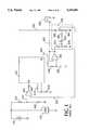
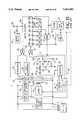
- FIG. 1The system of the above-referenced patent, including, in detail, aspects thereof particularly relevant to the present disclosure, is shown schematically on FIG. 1.
- the same reference numeralshave been used, except that, in the present FIG. 1, those reference numerals are preceded by the numeral "6".
- the present inventionis applicable to other battery monitoring systems, as will be described later, but the operation of the system of the above-referenced patent will be set forth in some detail for background on the operation of such systems generally.
- the metering systemis connected to an electric storage battery 610 and to a load 616.
- a fixed fraction of the battery voltageis supplied from a voltage divider consisting of resistors 626 and 628 through a connection 632 to a threshold comparator 634.
- the fixed fraction of the battery voltageis compared by comparator 634 with a reference voltage supplied through a connection 636 from a reference voltage slope network 638 which is described more fully below.
- comparator 634Whenever load is applied to battery 610, the resultant downward excursion in the battery terminal voltage is detected by comparator 634. If the downward excursion is below a threshold, as determined by the reference voltage on connection 636, a resultant signal is provided to a digital circuit unit 642 at "IN" through a resistor 640.
- Digital circuit unit 642generates a continuous series of voltage pulses at output terminal "FB" to output connection 646, the voltage pulses respectively corresponding in length to the binary digital value stored in the digital circuit unit.
- the pulsesare then filtered in a low pass filter combination consisting of a resistor 648 and a capacitor 650 to provide a substantially smooth analog output voltage signal having a voltage amplitude corresponding to the binary digital value stored in digital circuit unit 642. That voltage is amplified by an operational amplifier 652 connected as a voltage follower amplifier.
- the resultant amplified output voltageoptionally may be supplied through a connection 654 to a voltmeter 656 to thereby visually indicate the state of charge of battery 610.
- a resistor 6131 and a capacitor 6132 connected to a clock oscillator (not shown) within digital circuit unit 642determine the frequency of operation of the unit and, therefore, the integration rate thereof.
- the output from amplifier 652is also supplied to reference voltage slope network 638 so that the network may generate a variable reference signal which is a function of the analog output voltage signal.
- the reference voltageis also determined in part by a substantially constant reference voltage signal on input connection 658, the constant reference voltage signal being derived from other portions of the system (not shown).
- the reference voltage output on connection 636 which sets the voltage threshold for comparator 634would be a constant fraction of the substantially constant reference voltage on input connection 658, as determined by voltage divider resistors 682 and 684.
- the input from amplifier 652is operable to reduce the threshold voltage level at connection 636 as the discharge of battery 610 progresses, as recorded by the integrator (not shown) contained within digital circuit unit 642. This is appropriate, since the terminal voltage of battery 610 will decrease for each load current level as the discharge of the battery progresses.
- the variable reference voltagemay approximate a nominal loaded open circuit battery terminal voltage at the various states of discharge of the battery.
- the voltage supplied through amplifier 652 to network 638may be characterized as a feedback voltage.
- the voltage output from amplifier 652 supplied to network 638is at its highest when battery 610 is fully charged and when the system is registering a fully charged condition.
- the voltage relationshipsare such that the voltage at the circuit node between resistors 674 and 676 is always somewhat below the voltage at the node between the vertical leg resistors 682 and 684 so that the cross connection formed by resistors 678 and 680 causes a downward translation of the voltage at the node between resistors 682 and 684 which is the output voltage reference on connection 636.
- Adjustment of variable resistor 678changes this downward offset, with reducing the value of the variable resistor increasing the offset, and increasing the value of the variable resistor reducing the offset.
- the voltage output level of amplifier 652is reduced and the reference voltage is correspondingly reduced, producing a sloping characteristic, or transform.
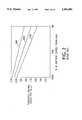
- This threshold reference voltage characteristicis illustrated on FIG. 2 as curve 686.
- Curve 686 on FIG. 2represents a plot of the threshold voltage output from network 638 on connection 636 versus the state of charge, as indicated by the numerical value stored in digital circuit unit 642. It will be seen that the voltage value slopes downwardly as the percent of charge remaining decreases, since the battery terminal voltage generally decreases as the charge is depleted and, therefore, the resulting lower voltage excursions on load look like heavier loads to the metering system.
- Curves 690 and 692 on FIG. 2illustrate the performance of network 638 with greater vertical displacements caused by successive reductions in the variable resistor 678. It is a very useful feature of network 638 that adjustments in the vertical displacement of the threshold voltage characteristic also provide an appropriate change in the slope of the characteristic. The main reason for providing the adjustments available from variable resistor 678 is to accommodate for different objectives of different users in terms of battery life versus maximum battery energy output per charge. For example, for a user who places the major emphasis on battery life, the battery must be considered as fully discharged at a higher specific gravity per cell, and at a higher final battery terminal voltage than would otherwise be attained. For that user, network 638 might be adjusted to provide for the voltage threshold curve 686. For another example, for a user who wishes to obtain more energy from the battery by discharging the battery more deeply, even though battery life may be compromised, one or the other of curves 690 and 692 might be selected by suitable adjustment of variable resistor 678.
- variable resistor 678It has been found that a "factory set" variable resistor 678 is quite satisfactory in most applications, where the factory setting takes into account anticipated usage of the battery. In other cases, however, setting of variable resistor 678 must be done in the field to account for unknown variables.
- the setting of variable resistor 678is a compromise in a single, simple adjustment to accommodate such variables as battery type, battery size, desired depth-of-discharge, and average loading.
- variable resistor 678is factory or field set
- variable resistor 678is quite satisfactory in applications in which batteries are used in a day's work with a "normal" statistical mix of loads and with a properly sized battery.
- providing variable resistor 678 with a "fixed” settingmay not be satisfactory when the types of use a battery encounters vary considerable from day to day.
- An example of such variable useis in a paper mill where, on one day, a battery-operated forklift truck might be used to relocate pallet loads of facial tissue, resulting in only light battery use and, on another day, the same forklift truck might be used to carry logs, requiring heavy battery use.
- Extreme variations in usecan also be compensated for by altering the integration rate, either with or without a change in threshold voltage.
- a metering systemfor measuring and indicating the state of charge of an electrical storage battery, comprising: means for storing a numerical value indicative of the state of charge of said battery and for providing an output voltage signal representative thereof; means for detecting the terminal voltage of said battery, coupled to said means for storing, and being operable to generate a function of said battery terminal voltage which is a substantially proportional fraction of said terminal voltage and to provide an input to said means for storing if said function is below a threshold variable reference voltage signal; means for receiving said output voltage signal and for generating said variable reference voltage signal therefrom, said variable reference voltage signal being lowered as a function of said output voltage signal as said output voltage signal indicates progressively lower states of charge; and means for measuring the level of current drawn from said battery and adjusting said means for receiving and generating, in proportion to said current level, such that said variable reference voltage signal will be greater or lesser depending on said current level.
- FIG. 1is schematic/block diagram illustrating one battery monitoring system to which the present invention may be applied.
- FIG. 2is a graphic representation of the threshold voltage locus at which battery discharge conditions are detected by the system of FIG. 1 during the course of a full battery discharge cycle, with different locus curves representing different feedback reference adjustments.
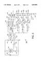
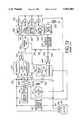
- FIG. 3is a schematic/block diagram illustrating one embodiment of the present invention.
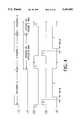
- FIGS. 4(A)-4(E)are waveform diagrams illustrating the operation of the embodiment of FIG. 3.
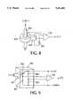
- FIGS. 5(A) and 5(B)are schematic/block and timing diagrams, respectively, illustrating another embodiment of the present invention.
- FIGS. 6(A) and 6(B)are waveform diagrams illustrating the operation of a portion of the embodiment of FIG. 5.
- FIGS. 7(A) and 7(B)are schematic/block and timing diagrams, respectively, illustrating an additional embodiment of the present invention.
- FIG. 8is a schematic/block diagram illustrating a further embodiment of the present invention, including a contactless (isolated) current related input.
- FIG. 9is a schematic/block diagram illustrating yet another embodiment of the present invention, including a pressure related input.
- FIG. 10is a schematic/block diagram illustrating yet an additional embodiment of the present invention, including a temperature related input.
- FIGS. 11(A) and 11(B)are schematic/block diagram and an operating matrix, respectively illustrating yet a further embodiment of the present invention, including a switch controlled input.
- FIGS. 12(A) and 12(B)are a schematic/block diagram and an operating matrix, respectively, illustrating another embodiment of the present invention.
- FIG. 13is a schematic/block diagram illustrating another battery monitoring system to which the present invention may be applied.
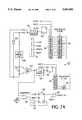
- FIG. 14is a schematic/block diagram illustrating the application of the present invention to the system of FIG. 13.
- FIG. 15is a schematic/block diagram illustrating an additional battery monitoring system to which the present invention may be applied.
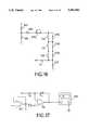
- FIG. 16is a schematic diagram illustrating an additional embodiment of the present invention.
- FIG. 17is a schematic diagram illustrating a further embodiment of the present invention.
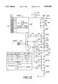
- FIG. 18is a block diagram illustrating the present invention controlled by a CPU.
- FIG. 19graphically illustrates a voltage signal conditioner transform for the system of FIG. 18.
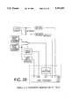
- FIG. 20is a single A/D converter modification of the system of FIG. 18.
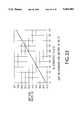
- FIG. 21graphically illustrates open circuit voltage stabilization for a hypothetical battery.
- FIG. 22graphically illustrates open circuit preset for the battery of FIG. 21.
- FIG. 23is a representation of error limits with the use of five threshold current levels.
- FIG. 24is a representation of integration thresholds and rates assigned to the six current zones defined by the threshold current levels of FIG. 23.
- FIG. 25graphically illustrates integration transforms for the six current zones of FIG. 24.
- FIG. 26is a representation of conversion intervals derived from the parameters of FIGS. 23-25.
- FIG. 27illustrates a wake up program for quiescent monitoring of a battery.
- FIG. 28graphically illustrates a quiescent integration threshold transform.
- FIGS. 1 and 2have been described above and, therefore, the description thereof is not repeated here.
- FIG. 3illustrates one system for adjusting the threshold voltage locus (FIG. 2) as a function of load current, the system being generally indicated by the reference numeral 600. Elements of system 600 common to the elements of the circuitry of FIG. 1 are given the same reference numerals. It will be seen that variable resistor 678 on FIG. 1 has been replaced with a series of switched resistors 678A, 678B, and 678C which are controlled as follows.
- a differential amplifier 700is connected across a low value shunt resistor 702 connected in series with load 616 which load may be assumed to be very variable, as described above.
- Shunt resistor 702may simply comprise a section of interconnecting cable with signal wires crimped into end terminations.
- the output of differential amplifier 700is inputted to a current integrator 704 which provides an output to comparators 706, 708, and 710, the comparators having high, medium, and low reference voltages, respectively, and the comparators providing data inputs to data flipflops 712, 714, and 716, respectively.
- Data flipflops 712, 714, and 716provide inputs to drivers 718, 720, and 722, respectively, which are operatively connected to switches 724, 726, and 728, respectively, the switches being connected, as shown, to selectively short out resistors 678C, 678B, and 678A, respectively.
- Current integrator 704is actually a voltage integrator which calculates the integral of current with respect to time by operating on the current-to-voltage conversation performed by shunt 702.
- the input to comparator 634(FIG. 1) has been removed from lead 632 and tied to an output from a sample/hold amplifier 740 which receives an input from a voltage integrator 742, the voltage integrator receiving an input from a voltage divider circuit comprising resistors 744 and 746 connected in series with battery 610.
- Sample/hold amplifier 740also receives a strobe signal from a sequencer circuit 750 which simultaneously strobes data flipflops 712, 714, and 716. Sequencer circuit 750 also provides reset signals to integrators 704 and 742.
- Switched resistors 678A-Chave four states: A+B+C, B+C, C, and short circuit, the states being set by the data values in data flipflops 712, 714, and 716, with the listing of the above states corresponding to increasing average current flow through shunt resistor 702 and lower average threshold voltage loci (FIG. 2).
- the main thrust of system 600is to roughly classify load regimes in which the system of FIG. 1 can operate normally and a high degree of precision is usually unnecessary. However, additional switching resistors could be provided for further refinement. As discussed earlier, the classifications are compromises to accommodate such battery statistics as battery type, battery size, average loading, and desired depth-of-discharge.
- Waveform (A)illustrates intervals of integration separated by very short intervals and waveform (B) illustrates the data which is being inputted to threshold comparator 634.
- Waveforms (C)-(D)are an enlargement of the short intervals between INTEGRATE A/INTEGRATE D and INTEGRATE B/INTEGRATE D on waveform (A), with waveform (C) showing portions of the integration periods, waveform (D) indicating the occurrences of strobes, and waveform (E) indicating periods of reset.
- integrators 742 and 704integrate current and voltage, respectively, during interval "A".
- sequencer 750strobes data ("B" on waveform (D) from sample/hold circuit 740 to comparator 634. Simultaneously, data flipflops 712, 714, and 716 are strobed and signals therein, if any, are transmitted to drivers 718, 720, and 722 to close switches 724, 726, and/or 728, respectively, providing a feedback reference voltage to threshold comparator 634. Integrators 742 and 704 are reset during interval “C” on waveform (E). Then, current and voltage are, again, integrated over interval "D” while digital circuit unit 642 operates normally using the "B" strobed information.
- the "B”, "E”, etc. strobescan be relatively short, on the order of about 10-100 microseconds, as they merely must command the current latches and the voltage samples prior to integrator resets during "C", "F”, etc. A short delay on the order of about 1-10 microseconds may separate the strobes and resets to preclude any error resulting from RESET starting before "hold” is fully established.
- Sample/hold amplifier 740samples and settles during the strobe pulse and holds during the zero interval.
- the total time allocated for STROBE, DELAY, and RESETshould be less than one percent of the full cycle; therefore, the reset should be less than 890 microseconds for a worst case consisting of a 100 millisecond cycle time, 100 microsecond strobe, and 10 microsecond delay.
- FIG. 5(A) and 5(B)illustrates a system, similar to system 600 on FIG. 3, but in which integration is digital, generally indicated by the reference numeral 50, where the input voltage integrator comprises a voltage-to-frequency converter 52 and a binary counter 54, the binary counter being connected to a latching register 56.
- the input current integratoris a voltage-to-frequency converter 60 and a binary counter 62, the binary counter being connected to a latching register 64.
- An AND gate 70receives a delay signal from voltage-to-frequency converter 52 and also receives a strobe signal from a sequencer 72.
- AND gate 70then outputs a strobe signal to transfer accumulated data from binary counter 54 to latching register 56, the strobe signal being synchronized with the "advance" pulses from the converter.
- the output of latching registers 56represents average battery voltage over the interval from the fall of RESET to the rise of STROBE presented in 12-bit binary form and may be received by a digital-to-analog converter (not shown) for use in system 600 (FIG. 3) or the output may be a direct digital input within a microprocessor based design (not shown), for the subsequent normal integration cycle of the system of FIG. 1.
- the output from latching register 64provides four levels of current defined in two-bit binary form and is used in a similar manner for the selection of feedback resistance in system 600 (FIG. 3). The intrusion into the input integration cycle is quite minimal, typically less than 0.01 percent (10 microseconds out of 100 milliseconds).
- Latching register 56must have relatively high resolution, usually all bits. Latching register 64 may have only two bits.
- System 50provides for omitting any cycle in which current drops to zero.
- a comparator 80is connected to receive the output of differential amplifier 700 and to receive a low current reference voltage. The output of comparator 80 is connected to flipflop 82 which provides inputs to AND gates 84 and 86 upon receiving a RECYCLE signal. Normally, upon receiving a RESET signal, AND gate 86 will output a RESET TO 0 signal to binary counter 54 which resets to zero. If, however, a low current condition is detected during a cycle, AND gate 84 will output a RESET TO 1 signal which drives the A counter to all "1"s, thus creating an impossibly high fictitious voltage, which causes digital circuit unit 642 (FIG. 3) to skip any cycle where the current has dropped to essentially zero sometime during the cycle. The current integral in the latter case is assumed to be corrupt.
- Creating synchronous strobesis required to prevent strobing data from the "A” or “C” binary counters into the "B” or “D” latching registers when the counters are in transition.
- the strobe signalis asynchronous with the advance pulses from the voltage-to-frequency converters and could occur while the counters are rippling through. This condition can be prevented by delaying the strobe slightly during such occurrences, as is described above.
- the voltage-to-frequency convertersgenerate a positive advance pulse precessed in time from a concurrent negative delay pulse.
- the timing diagram shown on FIGS. 6(A)-(D)describes five conditions. The first condition illustrates when ADVANCE and STROBE events are far apart.
- the remaining four conditionsshow accidental edge alignments and illustrate the salutary effect of the delay when accidental edge alignments occur.
- the delay and advanceare 1 microsecond wide each with 1/2 microsecond overlap.
- the strobeis 2 microseconds wide.
- the countersadvance on the leading edge of ADVANCE and strobing into latches occurs on leading edge of SYNCHRONOUS STROBE.
- FIGS. 7(A) and 7(B)illustrates a system similar to system 50 (FIGS. 5(A) and 5(B)), generally indicated by the reference numeral 50', in which synchronous strobes are generated by synchronizing the ADVANCE outputs to a clock precessed from STROBE.
- a data flipflop 90receives a input from voltage-to-frequency converter 52 and the data is transferred to binary counter 54 upon receipt of a precessed clock pulse.
- a data flipflop 92similarly transfers data to binary counter 62 from voltage-to-frequency converter 60.
- a low current conditionis again detected by comparator 80 which provides an input to an AND gate 94, coupled to a data flipflop 82', which AND gate also receives as an input the inverting output of the data flipflop.
- the output of data flipflop 82'is an input to an AND gate 84' which also receives a PRESET signal. If a low current condition exists during a cycle, the RESET signal to data flipflop 82' will output a signal to AND gate 84' which will output a PRESET TO 1 signal upon receipt of a PRESET signal.
- a 250 KHz clockruns continuously and all clock advances and strobing are on rising edges. PRESET and RESET occur during positive clock pulses. Voltage-to-frequency pulse width should be five microseconds minimum. Thus, the output of latching counters 56 is the average battery voltage integrated over 99.993 milliseconds (100 milliseconds-7 microseconds), less the digitizing error involved in synchronization.
- a Hall effect current sensormay be placed adjacent or surrounding a current carrying conductor without making physical contact therewith, and such is shown on FIG. 8.
- one end of a Hall effect sensor 800is inserted in a gap of a flux concentrating core 802 encircling a current carrying conductor 804 (with insulation intact), with the latter assumed to be a power cable connected to a battery being monitored (not shown).
- Hall effect sensor 800operates on Ampere's Law which states that the line integral of the magnetic field is proportional to the net current flow through the central aperture of core 802 and the sensor transduces the product of the perpendicular magnetic flux and the bias current generated by current generator 806 into a third, perpendicular Hall voltage. The latter, relatively low voltage is multiplied by differential amplifier 700 to the much higher level required by current integrator 704 (FIG. 3), for example.
- Such sensorsare quite inexpensive, but they suffer from poor accuracy in terms of both offset and gain. However, in a two or three classification zone system, their accuracy is sufficient. Current consumption of such sensors tends to be high, but this is of little importance in industrial vehicles such as forklift trucks.
- FIG. 9illustrates such an arrangement in which there is provided a pressure transducer 850 which includes a diaphragm 852 therein to flex in response to pressure "P" received from a hydraulic line (not shown).
- the flexureunbalances an arm of a piezoresistive bridge comprising four resistors 860-863 and the unbalance is measured and amplified differentially by differential amplifier 700 to produce an output proportional to the input pressure and, therefore, proportional to battery current.
- FIG. 10illustrates such an arrangement in which differential amplifier 700 receives inputs from a temperature sensing device 100 in proximity to a device heated by load current and from a temperature sensing device 102 sensing ambient temperature.
- This arrangementis particularly effective when loading is prolonged such that the thermal time constant falls well within the realm of the day's integration. These might be a two-minute time constant and two-hour integrals, for example.
- the situationcan be forced a bit by using an element with a fast time constant such as a fuse or a purposeful constriction.
- This arrangementis best used with a small number of classification zones, such as two or three.
- Thermal sensors 100 and 102can be band gap silicon sensors, silicon resistors, silicon P-N junctions, thermistors, thermocouples, or high temperature coefficient wires, for example.
- Resistors 156 and 158drop the battery voltage to about the level of a logical "1" for electronic logic components.
- a direct current signallogical "1” is applied directly to the inputs of AND gates 162 and 164 and a logical “0” is applied to AND gates 164 and 166 through an inverter 168.
- contactor 154is closed, a direct current signal, logical "1” is applied directly to AND gates 162 and 166 and a logical “0” is applied to AND gates 160 and 164 through an inverter 170.
- Shunt resistors 172 and 174are provided to create logical "0"s, respectively, when contactors 152 and/or 154 are open. Zener diodes 172 and 174 are provided to protect the logic circuitry against damage from voltage spikes.
- FIG. 12illustrates circuitry interfaced with systems 50 or 50' (FIGS. 5(A) and 5(B) and FIGS. 7(A) and 7(B) whereby the smoothing for any particular load regime can be improved by adjusting the integration rate commensurate with that regime, as well as the integration feedback transform.
- resistor 6131 (FIG. 1) of digital circuit unit 642has been replaced with switched resistors 6131A-C plus resistor 6131-D to provide selective adjustment of the master oscillator period over a range of interest, in the same manner as variable resistor 678 was replaced with switched resistors 678A-C.
- Resistors 6131A-Care operatively connected to drivers 764, 762, and 760, respectively, which drivers are connected to latching register 64 through an AND gate 770 and an OR gate 772 to provide the progression shown in the logic table.
- FIGS. 5(A) and 5(B) and FIGS. 7(A) and 7(B)A variation from systems 50 and 50' (FIGS. 5(A) and 5(B) and FIGS. 7(A) and 7(B) is that latching register 56 has been replaced with an analog-to-digital converter 56' having internal latches.
- the circuitry shown on FIGS. 12(A) and 12(B)smooths one- to two-hour work cycles with, say, 3/8- to 5/8-hour open loop integration times, whereas 5- to 8-hour work cycles are smoothed better at, say, 2- to 3-hour open loop integration times.
- the circuitrycan be tuned to a high degree of accuracy and linearity by adjusting feedback transform shape against real time rates.
- a drawback with altering the master oscillatoris that other functions such as reset routines and alarm signals will vary in frequency. In practice, this is compensated for by shifting the frequency internal to digital circuit unit 642 (FIG. 3) to a point where it impacts only the integration rate. A digital switching network can be employed for this function.
- FIGS. 12(A) and 12(B)illustrates an embodiment of the present invention in which both integration feedback transform and integration rate are adjusted with respect to load
- FIGS. 12(A) and 12(B)illustrates an embodiment of the present invention in which both integration feedback transform and integration rate are adjusted with respect to load
- FIGS. 12(A) and 12(B)illustrates an embodiment of the present invention in which both integration feedback transform and integration rate are adjusted with respect to load
- adjustment of integration rate onlyare adjusted with respect to load
- Such an arrangementcan be implemented especially easily in a microprocessor-based implementation.
- the 6131 statewould be varied, while the 678 state would remain constant.
- the apparatus therein describedcomprises means for sensing reductions in the output terminal voltage of a battery due to varying load conditions and producing a signal in response thereto during the time that the terminal voltage of the battery is below a threshold value.
- the apparatusfurther comprises integrator means such as an electronic counter or stepping motor for integrating the signal and means for displaying the integral accumulated by the integrating means.
- FIG. 13is a reproduction of FIG. 7 of the foregoing patent and includes a voltage controlled oscillator 235 which provides a signal to a stepper motor driver amplifier 237 which drives a stepper motor (not shown on FIG. 13) which is coupled to and rotates a "fuel gauge" from “full” to "empty” as a battery 201 is depleted.
- a comparator 241compares the output voltage of battery 201 with a reference voltage 227 and provides a voltage input to voltage controlled oscillator 235 through a resistor 243 when the output voltage of the battery drops below a predetermined threshold.
- resistor 243By replacing resistor 243 with a series of stepped resistors 243A-C plus resistor 243-D, and interfacing them with the integration circuitry of FIG. 12(A), as is indicated on FIG. 14, the rate of change in the fuel gauge reading can be selectively varied depending on the classification of load conditions, as is described in more detail above.
- the apparatus described thereincomprises threshold means for sensing reductions below a threshold level in the output terminal voltage of the battery and for producing a signal in response thereto and means for integrating the signal over a plurality of such reductions.
- FIG. 15 hereofis a reproduction of FIG. 2 of the foregoing patent and includes a tracking comparator 35' which compares the output level of a battery 1 to a reference voltage source 27.
- a self-resetting integrator 39'produces a train of pulses in response to tracking comparator 35', the rate of which is determined by variable resistor 63.
- Tracking comparator 35'also receives an input from feedback resistor 53'. It can be seen that variable resistor 63 and feedback resistor 53' are directly analogous to resistors 6131 and 678, respectively, of the system of FIG. 1 and, therefore, can be replaced with series of switched resistors 678A-C and 6131A-C plus resistor 6131-D in the manner shown on FIG. 12.
- a single adjustmentis used to accommodate both loading statistics (i.e., type of use) and desired depth-of-discharge. This is done for low cost and simplicity.
- the feedback transformtypically translates and rotates simultaneously via a single potentiometer adjustment, resistor 678.
- a second adjustment for use selection of depth-of-discharge independent of automatic rate correctionis shown on FIG. 16.
- a variable resistor 678Dis placed in series with switched resistors 678A-C as a modification to the arrangement shown on FIG. 3.
- Series/parallel combinations and variable adjustment of resistors 682 and/or 684are other possibilities depending upon specific loading statistics of the battery being modeled.
- these loading statisticsinclude battery type, battery size, and average loading, in addition to desired depth-of-discharge.
- the above embodiments of the present inventionare directed to operating on the main integrator to vary inputs thereto or to vary the integration rate thereof.
- a somewhat superior approachin some cases, would be to permit the main integrator to range over the full capacity of the battery, but to calibrate the output circuitry to display only the region which the user chooses to describe as the nominal capacity, e.g., 60%, 70%, 80%, or etc. of rated range/capacity.
- Broken line 654can be replaced with the circuitry shown on FIG. 17.
- a single variable gain amplifier 190is connected to the output of amplifier 652 to provide an input to voltmeter 656.
- the +5 voltsis conveniently derived from the DC input to digital circuit unit 642, as this voltage is precisely equal to the "FB" output when the main integrator is full.
- the gain of the amplifiermay vary from 1.0 to 2.0 by varying R Y from 0 to R X Ohms.
- FIGS. 1 and 13Each of the systems illustrated in FIGS. 1 and 13 is also referred to herein as a "933 system". These systems can be modified for automatic adjustment through use of the teachings set forth above which employ relatively imprecise (5 to 10% maximum error) load related signals as correction inputs according to the general method and a number of explicit apparatus modifications to the 933 systems. These and other composite systems are sometimes hereinafter referred to as the “AA933" (Automatic Adjustment 933).
- AA933Automatic Adjustment 933
- Sections 2.0 through 5.0further describe the AA933 method and Apparatus in terms of algorithms and procedures which permit direct implementation within a general purpose computer or microprocessor based central processing unit. They illustrate a practical example of load control where the load correction input is battery current.
- the Block Diagram shown in FIG. 18is at the most fundamental level required to accurately support all aspects of the AA933 method.
- the two critical signal paths through the voltage signal conditioning circuit and the current signal conditioning circuitrequire quality potentiometric input terminations.
- the voltage signal inputsshould come from vehicular system nodes as close to the battery connector as possible.
- the current signal inputsshould come from an integrated cable assembly with sufficient tolerancing controls on length, cross sectional area, and termination integrity to assure that the resultant voltage drop at the potentiometric signal wires is accurate to ⁇ 10% over the anticipated operational cable temperature range.
- the central processing unitis shown including the A-D converters and the output encoder. They could, of course, be separate elements.
- the signal conditioning and zero current detection functionsare shown in their most likely positions (external to the CPU).
- the signal levelsshould be on the order of 100 to 200 millivolts at peak current to minimize the effects of thermal voltages, noise, signal conditioning offset voltage, etc. Care should be taken to minimize the number of dissimilar metal connections, and if they must occur they should be isothermally paired within the potentiometric loop. Unbalanced Seebeck voltages on the order of tens of microvolts per differential degree Celsius may result, which can have a major effect on low current error and on zero current detection.
- the signal conditionermay also contain low pass filtering as determined by practical noise and A-D considerations.
- the zero current detectorcan also benefit from using the higher level output signal provided that filter requirements do not conflict with tracking (Refer to 2.3).
- the primary function of the zero current detectoris one or continuous zero (very low) current surveillance for the purpose of casting out corrupted A-D integration intervals.
- the only data the AA933 should act upon during its voltage-under-load operationis continuous load data.
- the zero current detectorshould be able to track reasonably fast relative to the A-D integration interval. If the current signal conditioner's filter precludes meeting this requirement the input(s) to the zero current detector will have to be moved forward to read the shunt directly, with the disadvantage of working from low levels.
- a secondary function of the zero current detectormay enter into a sub algorithm involving inactive battery monitoring (Refer to 5.0).
- the zero current detectorshould reliably detect the near-zero condition taking into account all offset and temperature dependent errors.
- a trigger level on the order of 500 microvolts to 1 millivolt referred to the shunt (approximately 25 to 50 millivolts referred to the output of the current signal conditioner)is practical.
- the primary function of the voltage signal conditioneris to precisely rescale the actual battery voltage range to an optimum voltage range for the A-D converter. Its secondary functions provide low pass filtration and transient protection. It is important that voltage measurements be made to a much higher precision than current measurements. As a goal voltage measurement error should be held to ⁇ 0.3% with a worst case error budget over the operating temperature regime on the order of ⁇ 0.7%. To this end, it is recommended that the voltage signal conditioner provide a clipped expanded scale input to the D-A converter, effectively increasing the D-A converter bit range relative to a zero based measurement.
- FIG. 19shows a typical transform restricting the output to the battery voltage range of interest to the AA933. It includes HVR (See 3.3) at the high voltage extreme and completed high rate discharge (See 4.0) at the low voltage extreme.
- A-D CONVERTERSANALOG-TO-DIGITAL CONVERTERS
- the A-D converter associated with the current signalcan operate with very few bits, as it is involved merely with a classification process. For this design example it will be assumed that it is a 6 bit converter operating on a 20 millisecond integration/conversion cycle.
- the voltage signal A-D convertermust, however, preserve the 0.3% error goal when working in conjunction with the expanded signal from the voltage signal conditioner. This is easy to achieve with a 10 bit converter, but may be achieved with an 8 bit converter by carefully treating all the elements within the temperature inclusive 0.7% overall error budget. For this design example it will be assumed that it is an 8 bit converter operating on a 20 millisecond integration/conversion cycle.
- the convertersmay be integrated within the CPU, as shown, or may be discrete external elements (or an 8 bit on-board and 10 bit off-board, etc.).
- the buffersare scaling and protection circuits which bring the unfiltered battery power down to safe limits for use by the core processor.
- the output encoderresponds to the computed state-of-charge stored in time core processor and translates it into whatever format is required externally.
- the state-of-chargewill typically be stored as a binary number, a binary coded decimal number or a hexadecimal number.
- the encoded outputwill typically be in a multiplexed seven segment format, a serial numeric code, a serial graphics code, or a serial address for a pointer display.
- the output encodermay be a separate function, but usually resides in the CPU as shown.
- the core processorcompletes the state-of-charge algorithm by operating on the voltage and current related inputs presented at the E, Z, and I ports (or the E/I and Z ports in the case of the single A-D converter) in conjunction with the power related inputs presented at the P and K ports.
- the functional descriptionappears in Sections 3.0, 4.0, and 5.0 of this document.
- the NVMholds the computed state-of-charge in memory whenever the power is disconnected.
- this memoryis an EEPROM integrated into the core processor as shown in FIGS. 18 and 20,
- the memorycould also be an off-board EEPROM or a battery back-up using, for example, a lithium manganese dioxide coin cell.
- the Standard 933contains two means for resetting the state-of-charge calculation to full, namely; OCR (open circuit reset) and HVR (high voltage reset). OCR functions after power is removed and reapplied. It is looking for a battery replacement or disconnected recharge. HVR is used with on-board charging where the 933 remains connected to the battery.
- the AA933When the power is removed and then a battery is reconnected the AA933 will test the open circuit voltage of that battery. If the voltage is above 2.09 VPC, or 50.16 volts for a 48 volt battery, the state-of-charge calculation is instructed to reset to full (100% S-0-C). If below, the S-0-C stored in memory will be recalled for use in the on-going calculations.
- the Standard 933allows for an adjustment of OCR from 2.00 VPC to 2.18 VPC for certain extraordinary applications. The vast majority of 933's are operated at the factory setting of 2.09 VPC. Almost all fixed calibration models (900 series) are set at 2.09 VPC. This voltage should be accurate to ⁇ 0.5% @ ⁇ 25° C. and ⁇ 0.7% over the operating temperature range.
- the OCR measurementis made once and only once upon power connect, usually within the time window of 1 to 5 seconds after first contact. If the delay is too short, contact bounce, slow connector engagement, and circuit non-stabilization will corrupt the measurement. If the time is too long the vehicle may be activated before the measurement is made.
- the HVR measurementlooks for a sustained high voltage condition in order to conclude that the battery has been substantially recharged.
- the Standard 933(factory setting) will reset to full if the battery voltage exceeds 2.35 VPC, or 56.4 volts for a 48 volt battery, for an uninterrupted 6 minute interval. These criteria are as strongly dependent upon the charger as they are upon the battery.
- the extreme practical voltage limitsare on the order of 2.30 VPC to 2.45 VPC.
- the upper time limitsmay extend to 2 or 3 hours to assure the last 20% of charge, but this is a severe operational restriction. Lower time limits are not recommended except in the case of pulse or reflex chargers, which have to be analyzed case-by-case. Voltage accuracy should be ⁇ 0.5% @25° C. and ⁇ 0.7% over the operating temperature range. Time accuracy is normally not critical, and an arbitrary control of ⁇ 25% is adequate.
- the advantage of an OCP initializationlies in its ability to interpolate intermediate charge states associated with the unknown battery.
- the major disadvantagelies in the need for a high degree of battery stabilization (hours to days). Until the battery stabilizes, the open circuit voltage will be high if last on charge and low if last on discharge.
- FIG. 21shows a hypothetical case for a relatively fast recovery lead acid traction battery.
- OCPa measurement of the battery voltage is made several seconds after connection (with the same considerations as OCR). This measurement is compared to the computed state-of-charge in accordance with the relationship shown in FIG. 22, The computed S-0-C is then incremented or decremented, as required, until the relationship reaches equilibrium. The loop is then locked out, and must not be reactivated until the next power down/power up cycle.
- the methodis described in detail above.
- This sectiondescribes the apparatus in terms of FIG. 18 with a 20 millisecond A-D integration/conversion cycle.
- the computed S-0-Cinvolves a form of integration which includes rate and differential voltage, but requires only addition and subtraction operations in the core processor.
- the current converterwill direct the use of one of six integration threshold transforms, the zero current detector will signal that only non-zero information was present throughout the interval (if current had flowed continuously), and the voltage converter will present the voltage for use within the algorithm being executed by the core processor.
- the Z port to the core processormonitors time activity from the zero current detector, and if any is found a flag is set. This flag instructs the processor to skip the interval, in essence it issues a zero (0) increment/decrement command. If the flag is not set the processor proceeds with the calculation.
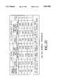
- thresholdsIn addition to instantaneous zero current detection there are five (5) short term integrated (via the 20 millisecond A-D conversion) current levels, or thresholds, recognized by the core processor. These are shown in FIG. 23 and are nominally 80, 170, 270, 380, and 500 amperes. The combined error of threshold detection, over the operating temperature range is held within ⁇ 11% to ⁇ 16% as shown in the table.
- the input voltage to the A-D convertercomes from the current signal conditioner operating with a gain of 48.4 as previously described in Section 2.2.
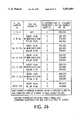
- the five (5) current thresholdsdefine six (6) integration zones. Each of these zones has an assigned integration threshold transform, a normal integration rate, and a fault detected integration rate, as shown in FIG. 24.
- the complete set of integration transforms converted to this 48 volt lead acid traction battery exampleis shown in FIG. 25 .Note that the transforms only cover the upper 80% of the battery's capacity in accordance with manufacturer's recommendations. The transforms could be extended to 100% depth-of-discharge, and then have the output encoder perform the desired range truncation, as described above. Truncation to depths-of-discharge less than 80% are best performed in the output encoder, thus preserving the full 80% range in the core processor.
- FIG. 26summarizes the eighteen possibilities for a conversion interval occurring at 50% computed state-of-charge where the integrator is storing the decimal number 360,000, and the A through F integration thresholds are 46.68, 46.08, 45.00, 43.92, 42.84, and 41.76 volts DC respectively.
- the zero current detectoris assumed to be set at 4 amperes.
- the core processorcontains the AA933's main integrator. This integrator is initialized by incrementing to the decimal number 720,000 via either OCR or HVR after "Full" battery detection. Alternatively, it can be initialized to any intermediate value by incrementing or decrementing, as required, via OCP.
- the integratorwill be allowed to decrement only, under control of the algorithm described in Section 4.3.
- This algorithmexamines the computed state-of-charge, the 20 millisecond integrated average battery voltage, the 20 millisecond integrated average battery current and the confirmation of continuous current flow after the completion of each 20 millisecond A-D conversion interval. This examination results in the identification of one-of-eighteen possibilities. Seven of these possibilities result in no subtraction. Two of the possibilities result in a subtraction of 1, one results in a subtraction of 2, one results in a subtraction of 4, two result in a subtraction of 6, three result in a subtraction of 8, and two result in a subtraction of 12.
- All batteriesself discharge. The differences are merely a matter of rate.
- the self discharge mechanismis primarily a function of electrochemistry, construction, temperature, age, and instantaneous state-of-charge. Large lead acid traction batteries might completely self discharge in 4 months when young and cool or 2 weeks when old and hot.
- the AA933can be configured to approximate the self-discharging charge state by using the stabilized open circuit voltage approximation. It is preferred that the integrator be allowed to decrement only after a long quiescent interval, say 8 to 24 hours. It is also important that the monitoring circuitry constitutes a negligible load on the battery. This can be accomplished by having a low power system, or a higher power system with periodic wake-ups from a low power quiescence detection time clock.
- the signal for quiescencemay come via the keyswitch or the zero current detector, after consideration is given to such practical aspects as power consumption, current detection resolution, standby loads, etc.
- FIG. 27shows a wake-up program for quiescent monitoring that allows the integrator to decrement by 1 for each 20 millisecond conversion during a 44 second wake-up interval.
- the first wake-upoccurs 8 hours after quiescence is first detected, and each subsequent wake-up is spaced at 1 hour intervals.
- FIG. 28shows a typical open circuit voltage transform which the integrator follows in its normal manner. This essentially introduces a seventh integration threshold transform, which is arbitrarily named Q. This Q transform assumes that the specific gravity of the battery varies from approximately 1.280 at full charge to approximately 1.150 at 80% depth-of-discharge.
Landscapes
- Chemical & Material Sciences (AREA)
- General Physics & Mathematics (AREA)
- Physics & Mathematics (AREA)
- Health & Medical Sciences (AREA)
- Life Sciences & Earth Sciences (AREA)
- Chemical Kinetics & Catalysis (AREA)
- Electrochemistry (AREA)
- Analytical Chemistry (AREA)
- Biochemistry (AREA)
- General Health & Medical Sciences (AREA)
- Immunology (AREA)
- Pathology (AREA)
- Molecular Biology (AREA)
- Tests Of Electric Status Of Batteries (AREA)
Abstract
Description
Claims (16)
Priority Applications (5)
| Application Number | Priority Date | Filing Date | Title |
|---|---|---|---|
| US08/224,072US5451881A (en) | 1993-12-10 | 1994-04-07 | Method and means for adjusting battery monitor based on rate of current drawn from the battery |
| KR1019960703092AKR960706635A (en) | 1993-12-10 | 1994-12-09 | BATTERY MONITOR ADJUSTED BY RATE OF CURRENT |
| EP95905962AEP0733203A4 (en) | 1993-12-10 | 1994-12-09 | BATTERY CONTROL DEVICE ADJUSTED BY THE CURRENT FLOW DRAWN THEREFROM |
| JP7516393AJPH09508968A (en) | 1993-12-10 | 1994-12-09 | Battery monitoring device adjusted by current rate |
| PCT/US1994/014492WO1995016200A1 (en) | 1993-12-10 | 1994-12-09 | Battery monitor adjusted by rate of current |
Applications Claiming Priority (2)
| Application Number | Priority Date | Filing Date | Title |
|---|---|---|---|
| US16608593A | 1993-12-10 | 1993-12-10 | |
| US08/224,072US5451881A (en) | 1993-12-10 | 1994-04-07 | Method and means for adjusting battery monitor based on rate of current drawn from the battery |
Related Parent Applications (1)
| Application Number | Title | Priority Date | Filing Date |
|---|---|---|---|
| US16608593AContinuation-In-Part | 1993-12-10 | 1993-12-10 |
Publications (1)
| Publication Number | Publication Date |
|---|---|
| US5451881Atrue US5451881A (en) | 1995-09-19 |
Family
ID=26861966
Family Applications (1)
| Application Number | Title | Priority Date | Filing Date |
|---|---|---|---|
| US08/224,072Expired - LifetimeUS5451881A (en) | 1993-12-10 | 1994-04-07 | Method and means for adjusting battery monitor based on rate of current drawn from the battery |
Country Status (5)
| Country | Link |
|---|---|
| US (1) | US5451881A (en) |
| EP (1) | EP0733203A4 (en) |
| JP (1) | JPH09508968A (en) |
| KR (1) | KR960706635A (en) |
| WO (1) | WO1995016200A1 (en) |
Cited By (205)
| Publication number | Priority date | Publication date | Assignee | Title |
|---|---|---|---|---|
| US5539318A (en)* | 1992-07-16 | 1996-07-23 | Toyota Jidosha Kabushiki Kaisha | Residual capacity meter for electric car battery |
| US5570025A (en)* | 1994-11-16 | 1996-10-29 | Lauritsen; Dan D. | Annunciator and battery supply measurement system for cellular telephones |
| WO1997024793A1 (en)* | 1995-12-29 | 1997-07-10 | H.E.F.O., Inc. | High efficiency dc motor with generator and flywheel characteristics |
| US5668465A (en)* | 1996-04-29 | 1997-09-16 | Operating Technical Electronics, Inc. | Battery voltage monitor and disconnection circuit |
| US5698965A (en)* | 1995-12-01 | 1997-12-16 | Flight Systems, Inc. | Apparatus and method for determining the current state of charge of a battery by monitoring battery voltage increases above and decreases below a threshold |
| US5726505A (en)* | 1995-01-13 | 1998-03-10 | Omron Corporation | Device to prevent reverse current flow, rectifier device and solar generator system |
| US5764034A (en)* | 1996-04-10 | 1998-06-09 | Baxter International Inc. | Battery gauge for a battery operated infusion pump |
| US5781013A (en)* | 1994-10-26 | 1998-07-14 | Fuji Jukogyo Kabushiki Kaisha | Battery management system for electric vehicle |
| US5841284A (en)* | 1994-11-11 | 1998-11-24 | Fujitsu Limited | Apparatus for monitoring power of battery to supply electric power to load |
| US5869951A (en)* | 1994-10-26 | 1999-02-09 | Fuji Jukogyo Kabushiki Kaisha | Battery management system for electric vehicle |
| US5929604A (en)* | 1997-06-18 | 1999-07-27 | Ericsson, Inc. | Battery-discharge-protection system for electronic accessories used in vehicles containing a battery |
| EP0845682A3 (en)* | 1996-11-29 | 1999-08-25 | Nec Corporation | Portable information terminal apparatus capable of correctly detecting power supply voltage |
| US5994876A (en)* | 1997-10-09 | 1999-11-30 | Abbott Laboratories | Battery capacity measurement circuit |
| US6011379A (en)* | 1997-03-12 | 2000-01-04 | U.S. Nanocorp, Inc. | Method for determining state-of-charge using an intelligent system |
| US6150823A (en)* | 1989-12-11 | 2000-11-21 | Canon Kabushiki Kaisha | Battery charge detecting variable loads |
| US6211653B1 (en) | 1999-12-20 | 2001-04-03 | Ford Global Technologies, Inc. | Method and apparatus for measuring the state-of-charge of a battery |
| US6222370B1 (en)* | 1998-03-13 | 2001-04-24 | Brian Walter Schousek | Universal battery monitor |
| US6225808B1 (en) | 2000-02-25 | 2001-05-01 | Midtronics, Inc. | Test counter for electronic battery tester |
| US6294897B1 (en) | 1999-09-01 | 2001-09-25 | Keith S. Champlin | Method and apparatus for electronically evaluating the internal temperature of an electrochemical cell or battery |
| US6294896B1 (en) | 1998-09-11 | 2001-09-25 | Keith S. Champlin | Method and apparatus for measuring complex self-immitance of a general electrical element |
| US6304087B1 (en)* | 2000-09-05 | 2001-10-16 | Midtronics, Inc. | Apparatus for calibrating electronic battery tester |
| US6313607B1 (en) | 1999-09-01 | 2001-11-06 | Keith S. Champlin | Method and apparatus for evaluating stored charge in an electrochemical cell or battery |
| US6313608B1 (en) | 1997-11-03 | 2001-11-06 | Midtronics, Inc. | Method and apparatus for charging a battery |
| US6316914B1 (en) | 1999-05-05 | 2001-11-13 | Midtronics, Inc. | Testing parallel strings of storage batteries |
| US6323650B1 (en) | 1999-04-08 | 2001-11-27 | Midtronics, Inc. | Electronic battery tester |
| US6329793B1 (en) | 1996-07-29 | 2001-12-11 | Midtronics, Inc. | Method and apparatus for charging a battery |
| US6332113B1 (en) | 1996-10-07 | 2001-12-18 | Midtronics, Inc. | Electronic battery tester |
| US6331762B1 (en) | 1997-11-03 | 2001-12-18 | Midtronics, Inc. | Energy management system for automotive vehicle |
| US6351102B1 (en) | 1999-04-16 | 2002-02-26 | Midtronics, Inc. | Automotive battery charging system tester |
| US6356083B1 (en)* | 2001-02-07 | 2002-03-12 | General Motors Corporation | State of charge algorithm for a battery |
| US6359441B1 (en) | 1999-04-30 | 2002-03-19 | Midtronics, Inc. | Electronic battery tester |
| US6363303B1 (en) | 1999-11-01 | 2002-03-26 | Midtronics, Inc. | Alternator diagnostic system |
| US6377053B1 (en)* | 1997-03-04 | 2002-04-23 | Sgs-Thomson Microelectronics S.R.L. | Device for detecting short-circuits |
| US6380716B1 (en)* | 2000-11-17 | 2002-04-30 | Curtis Instruments, Inc. | Condition monitoring of opportunity charged batteries |
| US6392414B2 (en) | 1997-01-13 | 2002-05-21 | Midtronics, Inc. | Electronic battery tester |
| US6417669B1 (en) | 2001-06-11 | 2002-07-09 | Keith S. Champlin | Suppressing interference in AC measurements of cells, batteries and other electrical elements |
| US6424158B2 (en) | 1998-07-27 | 2002-07-23 | Midtronics, Inc. | Apparatus and method for carrying out diagnostic tests on batteries and for rapidly charging batteries |
| US6441585B1 (en) | 1999-06-16 | 2002-08-27 | Midtronics, Inc. | Apparatus and method for testing rechargeable energy storage batteries |
| US6445158B1 (en) | 1996-07-29 | 2002-09-03 | Midtronics, Inc. | Vehicle electrical system tester with encoded output |
| US6456988B1 (en) | 1997-03-12 | 2002-09-24 | U.S. Nanocorp Inc. | Method for determining state-of-health using an intelligent system |
| US6456045B1 (en) | 1999-04-16 | 2002-09-24 | Midtronics, Inc. | Integrated conductance and load test based electronic battery tester |
| US6466025B1 (en) | 2000-01-13 | 2002-10-15 | Midtronics, Inc. | Alternator tester |
| US6466026B1 (en) | 2001-10-12 | 2002-10-15 | Keith S. Champlin | Programmable current exciter for measuring AC immittance of cells and batteries |
| US6469511B1 (en) | 2001-07-18 | 2002-10-22 | Midtronics, Inc. | Battery clamp with embedded environment sensor |
| US6489786B1 (en)* | 1999-10-25 | 2002-12-03 | Yazaki Corporation | Non-isolated type voltage sensor |
| US20030034770A1 (en)* | 2001-08-10 | 2003-02-20 | Shakti Systems, Inc. | Current derivative sensor |
| US6544078B2 (en) | 2001-07-18 | 2003-04-08 | Midtronics, Inc. | Battery clamp with integrated current sensor |
| US6566883B1 (en) | 1999-11-01 | 2003-05-20 | Midtronics, Inc. | Electronic battery tester |
| US6586941B2 (en) | 2000-03-27 | 2003-07-01 | Midtronics, Inc. | Battery tester with databus |
| US6633165B2 (en) | 1997-11-03 | 2003-10-14 | Midtronics, Inc. | In-vehicle battery monitor |
| US20030214268A1 (en)* | 2002-04-15 | 2003-11-20 | Friwo Geraetebau Gmbh | Device and method for the detection of a charging voltage |
| US20030231006A1 (en)* | 2002-06-12 | 2003-12-18 | Kazuo Tojima | Deterioration degree calculating apparatus and deterioration degree calculating method for a battery |
| US6696819B2 (en) | 2002-01-08 | 2004-02-24 | Midtronics, Inc. | Battery charge control device |
| US6701262B2 (en)* | 2000-08-23 | 2004-03-02 | Autonetworks Technologies, Ltd. | Current detecting circuit |
| US6737831B2 (en) | 1999-09-01 | 2004-05-18 | Keith S. Champlin | Method and apparatus using a circuit model to evaluate cell/battery parameters |
| US20040128089A1 (en)* | 2002-12-29 | 2004-07-01 | Evgenij Barsoukov | Circuit and method for determining battery impedance increase with aging |
| US6759849B2 (en) | 2000-03-27 | 2004-07-06 | Kevin I. Bertness | Battery tester configured to receive a removable digital module |
| US20040148111A1 (en)* | 2003-01-23 | 2004-07-29 | Gauthier Claude R. | Embedded integrated circuit aging sensor System |
| US6781382B2 (en) | 2002-12-05 | 2004-08-24 | Midtronics, Inc. | Electronic battery tester |
| US6788025B2 (en) | 2001-06-22 | 2004-09-07 | Midtronics, Inc. | Battery charger with booster pack |
| US6795782B2 (en) | 1999-04-08 | 2004-09-21 | Midtronics, Inc. | Battery test module |
| US20040189255A1 (en)* | 2002-08-31 | 2004-09-30 | Vb Autobatterie Gmbh | Method for determining the amount of charge which can be drawn on a storage battery, and monitoring device for a storage battery |
| US20040248001A1 (en)* | 2003-06-03 | 2004-12-09 | Hall David R. | Pressure-compensated downhole battery |
| US6850037B2 (en) | 1997-11-03 | 2005-02-01 | Midtronics, Inc. | In-vehicle battery monitor |
| US6871151B2 (en) | 1997-11-03 | 2005-03-22 | Midtronics, Inc. | Electronic battery tester with network communication |
| US6885195B2 (en) | 1996-07-29 | 2005-04-26 | Midtronics, Inc. | Method and apparatus for auditing a battery test |
| US6888468B2 (en) | 2003-01-22 | 2005-05-03 | Midtronics, Inc. | Apparatus and method for protecting a battery from overdischarge |
| US6891378B2 (en) | 2003-03-25 | 2005-05-10 | Midtronics, Inc. | Electronic battery tester |
| US6906522B2 (en) | 2002-03-29 | 2005-06-14 | Midtronics, Inc. | Battery tester with battery replacement output |
| US6906523B2 (en) | 2000-09-14 | 2005-06-14 | Midtronics, Inc. | Method and apparatus for testing cells and batteries embedded in series/parallel systems |
| US6914413B2 (en) | 1996-07-29 | 2005-07-05 | Midtronics, Inc. | Alternator tester with encoded output |
| US6913483B2 (en) | 2003-06-23 | 2005-07-05 | Midtronics, Inc. | Cable for electronic battery tester |
| US6919725B2 (en) | 2003-10-03 | 2005-07-19 | Midtronics, Inc. | Electronic battery tester/charger with integrated battery cell temperature measurement device |
| US6930485B2 (en) | 2002-03-14 | 2005-08-16 | Midtronics, Inc. | Electronic battery tester with battery failure temperature determination |
| US6941234B2 (en) | 2001-10-17 | 2005-09-06 | Midtronics, Inc. | Query based electronic battery tester |
| US6967484B2 (en) | 2000-03-27 | 2005-11-22 | Midtronics, Inc. | Electronic battery tester with automotive scan tool communication |
| EP1274991A4 (en)* | 2000-04-04 | 2005-12-07 | Microchip Tech Inc | Current measuring apparatus for battery |
| US7003410B2 (en) | 1996-07-29 | 2006-02-21 | Midtronics, Inc. | Electronic battery tester with relative test output |
| US7012433B2 (en) | 2002-09-18 | 2006-03-14 | Midtronics, Inc. | Battery tester upgrade using software key |
| US7015674B2 (en) | 2001-06-22 | 2006-03-21 | Midtronics, Inc. | Booster pack with storage capacitor |
| US7039533B2 (en) | 1999-04-08 | 2006-05-02 | Midtronics, Inc. | Battery test module |
| US20060113934A1 (en)* | 2004-12-01 | 2006-06-01 | Maeda Metal Industries, Ltd. | Electric tightening device |
| US7058525B2 (en) | 1999-04-08 | 2006-06-06 | Midtronics, Inc. | Battery test module |
| US20060125319A1 (en)* | 2004-12-15 | 2006-06-15 | King Robert D | System and method for providing power control of an energy storage system |
| US7081755B2 (en) | 2002-09-05 | 2006-07-25 | Midtronics, Inc. | Battery tester capable of predicting a discharge voltage/discharge current of a battery |
| US7106070B2 (en) | 2004-07-22 | 2006-09-12 | Midtronics, Inc. | Broad-band low-inductance cables for making Kelvin connections to electrochemical cells and batteries |
| US7116109B2 (en) | 2003-11-11 | 2006-10-03 | Midtronics, Inc. | Apparatus and method for simulating a battery tester with a fixed resistance load |
| US7119686B2 (en) | 2004-04-13 | 2006-10-10 | Midtronics, Inc. | Theft prevention device for automotive vehicle service centers |
| US20060226844A1 (en)* | 2005-03-30 | 2006-10-12 | Broad Alan S | Battery monitoring circuit and method |
| US7126341B2 (en) | 1997-11-03 | 2006-10-24 | Midtronics, Inc. | Automotive vehicle electrical system diagnostic device |
| US7154276B2 (en) | 2003-09-05 | 2006-12-26 | Midtronics, Inc. | Method and apparatus for measuring a parameter of a vehicle electrical system |
| US7198510B2 (en) | 2001-11-14 | 2007-04-03 | Midtronics, Inc. | Kelvin connector for a battery post |
| US7208914B2 (en) | 2002-12-31 | 2007-04-24 | Midtronics, Inc. | Apparatus and method for predicting the remaining discharge time of a battery |
| US7246015B2 (en) | 1996-07-29 | 2007-07-17 | Midtronics, Inc. | Alternator tester |
| US7276893B2 (en)* | 2005-02-28 | 2007-10-02 | Keithley Instruments, Inc. | Automatic ranging current shunt |
| US7319304B2 (en) | 2003-07-25 | 2008-01-15 | Midtronics, Inc. | Shunt connection to a PCB of an energy management system employed in an automotive vehicle |
| EP1876461A3 (en)* | 2000-04-04 | 2008-01-23 | Microchip Technology Incorporated | Current measuring apparatus for battery |
| US7398176B2 (en) | 2000-03-27 | 2008-07-08 | Midtronics, Inc. | Battery testers with secondary functionality |
| US7408358B2 (en) | 2003-06-16 | 2008-08-05 | Midtronics, Inc. | Electronic battery tester having a user interface to configure a printer |
| US7446536B2 (en) | 2000-03-27 | 2008-11-04 | Midtronics, Inc. | Scan tool for electronic battery tester |
| US7479763B2 (en) | 2001-06-22 | 2009-01-20 | Midtronics, Inc. | Apparatus and method for counteracting self discharge in a storage battery |
| US7498767B2 (en) | 2005-02-16 | 2009-03-03 | Midtronics, Inc. | Centralized data storage of condition of a storage battery at its point of sale |
| US7501795B2 (en) | 2001-06-22 | 2009-03-10 | Midtronics Inc. | Battery charger with booster pack |
| US7505856B2 (en) | 1999-04-08 | 2009-03-17 | Midtronics, Inc. | Battery test module |
| US7545146B2 (en) | 2004-12-09 | 2009-06-09 | Midtronics, Inc. | Apparatus and method for predicting battery capacity and fitness for service from a battery dynamic parameter and a recovery voltage differential |
| US7595643B2 (en) | 2003-11-11 | 2009-09-29 | Midtronics, Inc. | Apparatus and method for simulating a battery tester with a fixed resistance load |
| US7598743B2 (en) | 2000-03-27 | 2009-10-06 | Midtronics, Inc. | Battery maintenance device having databus connection |
| US7598699B2 (en) | 2004-02-20 | 2009-10-06 | Midtronics, Inc. | Replaceable clamp for electronic battery tester |
| US7598744B2 (en) | 2000-03-27 | 2009-10-06 | Midtronics, Inc. | Scan tool for electronic battery tester |
| US7642786B2 (en) | 2004-06-01 | 2010-01-05 | Midtronics, Inc. | Battery tester capable of identifying faulty battery post adapters |
| WO2010000536A1 (en)* | 2008-07-04 | 2010-01-07 | Robert Bosch Gmbh | Method and device for estimating battery charge state |
| US7688074B2 (en) | 1997-11-03 | 2010-03-30 | Midtronics, Inc. | Energy management system for automotive vehicle |
| US7706991B2 (en) | 1996-07-29 | 2010-04-27 | Midtronics, Inc. | Alternator tester |
| US7705602B2 (en) | 1997-11-03 | 2010-04-27 | Midtronics, Inc. | Automotive vehicle electrical system diagnostic device |
| US7710119B2 (en) | 2004-12-09 | 2010-05-04 | Midtronics, Inc. | Battery tester that calculates its own reference values |
| US7723993B2 (en) | 2002-09-05 | 2010-05-25 | Midtronics, Inc. | Electronic battery tester configured to predict a load test result based on open circuit voltage, temperature, cranking size rating, and a dynamic parameter |
| US7774151B2 (en) | 1997-11-03 | 2010-08-10 | Midtronics, Inc. | Wireless battery monitor |
| US7772850B2 (en) | 2004-07-12 | 2010-08-10 | Midtronics, Inc. | Wireless battery tester with information encryption means |
| US7777612B2 (en) | 2004-04-13 | 2010-08-17 | Midtronics, Inc. | Theft prevention device for automotive vehicle service centers |
| US7791348B2 (en) | 2007-02-27 | 2010-09-07 | Midtronics, Inc. | Battery tester with promotion feature to promote use of the battery tester by providing the user with codes having redeemable value |
| US7808375B2 (en) | 2007-04-16 | 2010-10-05 | Midtronics, Inc. | Battery run down indicator |
| US20100259242A1 (en)* | 2009-04-14 | 2010-10-14 | Ford Global Technologies, Llc | Method and system for monitoring temperatue of a power distribution circuit |
| US20100324847A1 (en)* | 2009-06-22 | 2010-12-23 | Quanta Computer Inc. | Battery gas-gauge circuit and method thereof |
| CN101957433A (en)* | 2009-07-15 | 2011-01-26 | 广达电脑股份有限公司 | Battery power measuring circuit and method thereof |
| US7977914B2 (en) | 2003-10-08 | 2011-07-12 | Midtronics, Inc. | Battery maintenance tool with probe light |
| US20110238341A1 (en)* | 2010-03-25 | 2011-09-29 | Mehdi Etezadi-Amoli | High Power DC Kilowatt Hour Meter |
| US8164343B2 (en) | 2003-09-05 | 2012-04-24 | Midtronics, Inc. | Method and apparatus for measuring a parameter of a vehicle electrical system |
| US8198900B2 (en) | 1996-07-29 | 2012-06-12 | Midtronics, Inc. | Automotive battery charging system tester |
| US8203345B2 (en) | 2007-12-06 | 2012-06-19 | Midtronics, Inc. | Storage battery and battery tester |
| US20120187916A1 (en)* | 2011-01-20 | 2012-07-26 | Gm Global Technology Operations, Inc. | Virtual Charge for Electric Vehicles |
| CN102680902A (en)* | 2012-05-11 | 2012-09-19 | 河南速达电动汽车科技有限公司 | Consistency on-line monitoring device and method for motive power battery pack for electric automobile |
| US8306690B2 (en) | 2007-07-17 | 2012-11-06 | Midtronics, Inc. | Battery tester for electric vehicle |
| US8344685B2 (en) | 2004-08-20 | 2013-01-01 | Midtronics, Inc. | System for automatically gathering battery information |
| US8436619B2 (en) | 2004-08-20 | 2013-05-07 | Midtronics, Inc. | Integrated tag reader and environment sensor |
| US8442877B2 (en) | 2004-08-20 | 2013-05-14 | Midtronics, Inc. | Simplification of inventory management |
| US8513949B2 (en) | 2000-03-27 | 2013-08-20 | Midtronics, Inc. | Electronic battery tester or charger with databus connection |
| US20130328567A1 (en)* | 2012-06-11 | 2013-12-12 | Casio Computer Co., Ltd. | Battery-type determination apparatus, battery-type determination method, and electronic apparatus |
| US8738309B2 (en) | 2010-09-30 | 2014-05-27 | Midtronics, Inc. | Battery pack maintenance for electric vehicles |
| US8810354B2 (en) | 2013-01-10 | 2014-08-19 | Eaton Corporation | Binary coded decimal resistive load and network |
| US20140239965A1 (en)* | 2013-02-22 | 2014-08-28 | GM Global Technology Operations LLC | Battery cell scanning systems and methods |
| US8872517B2 (en) | 1996-07-29 | 2014-10-28 | Midtronics, Inc. | Electronic battery tester with battery age input |
| US8958998B2 (en) | 1997-11-03 | 2015-02-17 | Midtronics, Inc. | Electronic battery tester with network communication |
| US8975898B2 (en)* | 2003-10-02 | 2015-03-10 | Kulite Semiconductor Products, Inc. | Shunt calibration for electronic pressure switches |
| US9018958B2 (en) | 2003-09-05 | 2015-04-28 | Midtronics, Inc. | Method and apparatus for measuring a parameter of a vehicle electrical system |
| CN104617617A (en)* | 2015-01-21 | 2015-05-13 | 衢州职业技术学院 | Self-adaptive storage battery charging device |
| US9201120B2 (en) | 2010-08-12 | 2015-12-01 | Midtronics, Inc. | Electronic battery tester for testing storage battery |
| US9229062B2 (en) | 2010-05-27 | 2016-01-05 | Midtronics, Inc. | Electronic storage battery diagnostic system |
| US9244100B2 (en) | 2013-03-15 | 2016-01-26 | Midtronics, Inc. | Current clamp with jaw closure detection |
| US9255955B2 (en) | 2003-09-05 | 2016-02-09 | Midtronics, Inc. | Method and apparatus for measuring a parameter of a vehicle electrical system |
| US9274157B2 (en) | 2007-07-17 | 2016-03-01 | Midtronics, Inc. | Battery tester for electric vehicle |
| US9312575B2 (en) | 2013-05-16 | 2016-04-12 | Midtronics, Inc. | Battery testing system and method |
| US9419311B2 (en) | 2010-06-18 | 2016-08-16 | Midtronics, Inc. | Battery maintenance device with thermal buffer |
| US9425487B2 (en) | 2010-03-03 | 2016-08-23 | Midtronics, Inc. | Monitor for front terminal batteries |
| US9475400B2 (en)* | 2010-12-10 | 2016-10-25 | General Electric Company | Charging device and methods for controlling a charging device |
| US9496720B2 (en) | 2004-08-20 | 2016-11-15 | Midtronics, Inc. | System for automatically gathering battery information |
| US9588185B2 (en) | 2010-02-25 | 2017-03-07 | Keith S. Champlin | Method and apparatus for detecting cell deterioration in an electrochemical cell or battery |
| US9851411B2 (en) | 2012-06-28 | 2017-12-26 | Keith S. Champlin | Suppressing HF cable oscillations during dynamic measurements of cells and batteries |
| US9923289B2 (en) | 2014-01-16 | 2018-03-20 | Midtronics, Inc. | Battery clamp with endoskeleton design |
| US9966676B2 (en) | 2015-09-28 | 2018-05-08 | Midtronics, Inc. | Kelvin connector adapter for storage battery |
| US9995611B2 (en) | 2012-03-30 | 2018-06-12 | Icu Medical, Inc. | Air detection system and method for detecting air in a pump of an infusion system |
| US10022498B2 (en) | 2011-12-16 | 2018-07-17 | Icu Medical, Inc. | System for monitoring and delivering medication to a patient and method of using the same to minimize the risks associated with automated therapy |
| US10046649B2 (en) | 2012-06-28 | 2018-08-14 | Midtronics, Inc. | Hybrid and electric vehicle battery pack maintenance device |
| US10046112B2 (en) | 2013-05-24 | 2018-08-14 | Icu Medical, Inc. | Multi-sensor infusion system for detecting air or an occlusion in the infusion system |
| US10166328B2 (en) | 2013-05-29 | 2019-01-01 | Icu Medical, Inc. | Infusion system which utilizes one or more sensors and additional information to make an air determination regarding the infusion system |
| US10222397B2 (en) | 2014-09-26 | 2019-03-05 | Midtronics, Inc. | Cable connector for electronic battery tester |
| US10317468B2 (en) | 2015-01-26 | 2019-06-11 | Midtronics, Inc. | Alternator tester |
| US10342917B2 (en) | 2014-02-28 | 2019-07-09 | Icu Medical, Inc. | Infusion system and method which utilizes dual wavelength optical air-in-line detection |
| US10430761B2 (en) | 2011-08-19 | 2019-10-01 | Icu Medical, Inc. | Systems and methods for a graphical interface including a graphical representation of medical data |
| US10429449B2 (en) | 2011-11-10 | 2019-10-01 | Midtronics, Inc. | Battery pack tester |
| US10463788B2 (en) | 2012-07-31 | 2019-11-05 | Icu Medical, Inc. | Patient care system for critical medications |
| US10473555B2 (en) | 2014-07-14 | 2019-11-12 | Midtronics, Inc. | Automotive maintenance system |
| US10596316B2 (en) | 2013-05-29 | 2020-03-24 | Icu Medical, Inc. | Infusion system and method of use which prevents over-saturation of an analog-to-digital converter |
| US10608353B2 (en) | 2016-06-28 | 2020-03-31 | Midtronics, Inc. | Battery clamp |
| US10635784B2 (en) | 2007-12-18 | 2020-04-28 | Icu Medical, Inc. | User interface improvements for medical devices |
| US10656894B2 (en) | 2017-12-27 | 2020-05-19 | Icu Medical, Inc. | Synchronized display of screen content on networked devices |
| US10707672B2 (en) | 2017-05-04 | 2020-07-07 | Intel Corporation | Methods and apparatus for battery current monitoring |
| US10843574B2 (en) | 2013-12-12 | 2020-11-24 | Midtronics, Inc. | Calibration and programming of in-vehicle battery sensors |
| US10850024B2 (en) | 2015-03-02 | 2020-12-01 | Icu Medical, Inc. | Infusion system, device, and method having advanced infusion features |
| US11054480B2 (en) | 2016-10-25 | 2021-07-06 | Midtronics, Inc. | Electrical load for electronic battery tester and electronic battery tester including such electrical load |
| US11135360B1 (en) | 2020-12-07 | 2021-10-05 | Icu Medical, Inc. | Concurrent infusion with common line auto flush |
| US11246985B2 (en) | 2016-05-13 | 2022-02-15 | Icu Medical, Inc. | Infusion pump system and method with common line auto flush |
| US11278671B2 (en) | 2019-12-04 | 2022-03-22 | Icu Medical, Inc. | Infusion pump with safety sequence keypad |
| US11325479B2 (en) | 2012-06-28 | 2022-05-10 | Midtronics, Inc. | Hybrid and electric vehicle battery maintenance device |
| US11324888B2 (en) | 2016-06-10 | 2022-05-10 | Icu Medical, Inc. | Acoustic flow sensor for continuous medication flow measurements and feedback control of infusion |
| US11344673B2 (en) | 2014-05-29 | 2022-05-31 | Icu Medical, Inc. | Infusion system and pump with configurable closed loop delivery rate catch-up |
| US11344668B2 (en) | 2014-12-19 | 2022-05-31 | Icu Medical, Inc. | Infusion system with concurrent TPN/insulin infusion |
| US11376973B2 (en) | 2009-04-14 | 2022-07-05 | Ford Global Technologies, Llc | Method and system for monitoring temperature of a power distribution circuit |
| US11474153B2 (en) | 2019-11-12 | 2022-10-18 | Midtronics, Inc. | Battery pack maintenance system |
| US11486930B2 (en) | 2020-01-23 | 2022-11-01 | Midtronics, Inc. | Electronic battery tester with battery clamp storage holsters |
| US11513160B2 (en) | 2018-11-29 | 2022-11-29 | Midtronics, Inc. | Vehicle battery maintenance device |
| US11545839B2 (en) | 2019-11-05 | 2023-01-03 | Midtronics, Inc. | System for charging a series of connected batteries |
| US11566972B2 (en) | 2019-07-31 | 2023-01-31 | Midtronics, Inc. | Tire tread gauge using visual indicator |
| EP4167457A1 (en)* | 2021-10-12 | 2023-04-19 | WAGO Verwaltungsgesellschaft mbH | Method and circuit arrangement for controlling a switched mode power supply |
| US11650259B2 (en) | 2010-06-03 | 2023-05-16 | Midtronics, Inc. | Battery pack maintenance for electric vehicle |
| US11668779B2 (en) | 2019-11-11 | 2023-06-06 | Midtronics, Inc. | Hybrid and electric vehicle battery pack maintenance device |
| US20230208179A1 (en)* | 2021-12-28 | 2023-06-29 | Makita Corporation | Battery charger |
| US11740294B2 (en) | 2010-06-03 | 2023-08-29 | Midtronics, Inc. | High use battery pack maintenance |
| US11883361B2 (en) | 2020-07-21 | 2024-01-30 | Icu Medical, Inc. | Fluid transfer devices and methods of use |
| US11973202B2 (en) | 2019-12-31 | 2024-04-30 | Midtronics, Inc. | Intelligent module interface for battery maintenance device |
| US12237482B2 (en) | 2019-12-31 | 2025-02-25 | Midtronics, Inc. | Intelligent module interface for battery maintenance device |
| US12320857B2 (en) | 2016-10-25 | 2025-06-03 | Midtronics, Inc. | Electrical load for electronic battery tester and electronic battery tester including such electrical load |
| US12330513B2 (en) | 2022-02-14 | 2025-06-17 | Midtronics, Inc. | Battery maintenance device with high voltage connector |
| US12350233B2 (en) | 2021-12-10 | 2025-07-08 | Icu Medical, Inc. | Medical fluid compounding systems with coordinated flow control |
| US12392833B2 (en) | 2022-05-09 | 2025-08-19 | Midtronics, Inc. | Electronic battery tester |
| USD1091564S1 (en) | 2021-10-13 | 2025-09-02 | Icu Medical, Inc. | Display screen or portion thereof with graphical user interface for a medical device |
Families Citing this family (10)
| Publication number | Priority date | Publication date | Assignee | Title |
|---|---|---|---|---|
| FR2754395B1 (en)* | 1996-10-03 | 1998-10-30 | Electricite De France | METHOD FOR DETERMINING THE ENERGY AVAILABLE IN A BATTERY, PARTICULARLY AN ELECTRIC VEHICLE AND GAUGE USING THE SAME |
| JP3508579B2 (en)* | 1998-10-27 | 2004-03-22 | 日本電気株式会社 | Charging circuit |
| JP4622119B2 (en)* | 2001-02-28 | 2011-02-02 | 富士電機システムズ株式会社 | Charge current detection circuit |
| KR100844806B1 (en)* | 2005-03-31 | 2008-07-07 | 주식회사 엘지화학 | Apparatus and method for measuring the amount of current in a battery cell using a plurality of detection resistors |
| JP2012018037A (en)* | 2010-07-07 | 2012-01-26 | Nec Energy Devices Ltd | Voltage measuring circuit and method |
| CN109991281B (en)* | 2018-01-02 | 2022-08-26 | 达尔生技股份有限公司 | Detection device and detection method |
| KR102266456B1 (en)* | 2019-07-24 | 2021-07-14 | 현대모비스 주식회사 | Lidar system and signal processing method thereof |
| DE102019125493B4 (en) | 2019-09-23 | 2025-03-20 | Infineon Technologies Ag | Slave device, bus system and procedure |
| US12095119B2 (en) | 2022-03-17 | 2024-09-17 | Infineon Technologies Ag | Error signaling on a separate output pin of a battery monitoring system |
| US11899516B1 (en) | 2023-07-13 | 2024-02-13 | T-Mobile Usa, Inc. | Creation of a digital twin for auto-discovery of hierarchy in power monitoring |
Citations (4)
| Publication number | Priority date | Publication date | Assignee | Title |
|---|---|---|---|---|
| US4017724A (en)* | 1975-06-27 | 1977-04-12 | Curtis Instruments, Inc. | Apparatus for measuring battery depletion by monitoring reductions in voltage |
| US4390841A (en)* | 1980-10-14 | 1983-06-28 | Purdue Research Foundation | Monitoring apparatus and method for battery power supply |
| US4453129A (en)* | 1980-01-14 | 1984-06-05 | Cristec Industries | Method for measuring the charge state of an accumulator and a device for implementing such method |
| US4560937A (en)* | 1981-11-16 | 1985-12-24 | Curtis Instruments, Inc. | Battery state of charge metering method and apparatus |
Family Cites Families (7)
| Publication number | Priority date | Publication date | Assignee | Title |
|---|---|---|---|---|
| US4320334A (en)* | 1980-10-01 | 1982-03-16 | General Electric Company | Battery state-of-charge indicator |
| JPS57206868A (en)* | 1981-06-12 | 1982-12-18 | Japan Storage Battery Co Ltd | Monitoring device for lead battery |
| JPS58501392A (en)* | 1981-08-26 | 1983-08-18 | キヤタピラ− インダストリアル インコ−ポレ−テツド | Potential monitoring display device |
| GB2121971B (en)* | 1982-06-12 | 1985-09-25 | Lucas Ind Plc | Battery state of charge evaluater |
| DE69218836T2 (en)* | 1991-06-20 | 1997-07-24 | Honda Motor Co Ltd | Device for determining the remaining capacity of a battery and as a warning when reducing this remaining capacity |
| JPH05203684A (en)* | 1992-01-24 | 1993-08-10 | Sharp Corp | Low battery detection circuit |
| US5321627A (en)* | 1992-03-11 | 1994-06-14 | Globe-Union, Inc. | Battery monitor and method for providing operating parameters |
- 1994
- 1994-04-07USUS08/224,072patent/US5451881A/ennot_activeExpired - Lifetime
- 1994-12-09KRKR1019960703092Apatent/KR960706635A/ennot_activeCeased
- 1994-12-09WOPCT/US1994/014492patent/WO1995016200A1/enactiveSearch and Examination
- 1994-12-09JPJP7516393Apatent/JPH09508968A/enactivePending
- 1994-12-09EPEP95905962Apatent/EP0733203A4/ennot_activeWithdrawn
Patent Citations (4)
| Publication number | Priority date | Publication date | Assignee | Title |
|---|---|---|---|---|
| US4017724A (en)* | 1975-06-27 | 1977-04-12 | Curtis Instruments, Inc. | Apparatus for measuring battery depletion by monitoring reductions in voltage |
| US4453129A (en)* | 1980-01-14 | 1984-06-05 | Cristec Industries | Method for measuring the charge state of an accumulator and a device for implementing such method |
| US4390841A (en)* | 1980-10-14 | 1983-06-28 | Purdue Research Foundation | Monitoring apparatus and method for battery power supply |
| US4560937A (en)* | 1981-11-16 | 1985-12-24 | Curtis Instruments, Inc. | Battery state of charge metering method and apparatus |
Cited By (291)
| Publication number | Priority date | Publication date | Assignee | Title |
|---|---|---|---|---|
| US6150823A (en)* | 1989-12-11 | 2000-11-21 | Canon Kabushiki Kaisha | Battery charge detecting variable loads |
| US5539318A (en)* | 1992-07-16 | 1996-07-23 | Toyota Jidosha Kabushiki Kaisha | Residual capacity meter for electric car battery |
| US5781013A (en)* | 1994-10-26 | 1998-07-14 | Fuji Jukogyo Kabushiki Kaisha | Battery management system for electric vehicle |
| US5869951A (en)* | 1994-10-26 | 1999-02-09 | Fuji Jukogyo Kabushiki Kaisha | Battery management system for electric vehicle |
| US6054861A (en)* | 1994-11-11 | 2000-04-25 | Fujitsu Limited | Apparatus for monitoring power of battery to supply electric power to load |
| US5841284A (en)* | 1994-11-11 | 1998-11-24 | Fujitsu Limited | Apparatus for monitoring power of battery to supply electric power to load |
| US5570025A (en)* | 1994-11-16 | 1996-10-29 | Lauritsen; Dan D. | Annunciator and battery supply measurement system for cellular telephones |
| US5726505A (en)* | 1995-01-13 | 1998-03-10 | Omron Corporation | Device to prevent reverse current flow, rectifier device and solar generator system |
| US5698965A (en)* | 1995-12-01 | 1997-12-16 | Flight Systems, Inc. | Apparatus and method for determining the current state of charge of a battery by monitoring battery voltage increases above and decreases below a threshold |
| WO1997024793A1 (en)* | 1995-12-29 | 1997-07-10 | H.E.F.O., Inc. | High efficiency dc motor with generator and flywheel characteristics |
| US5764034A (en)* | 1996-04-10 | 1998-06-09 | Baxter International Inc. | Battery gauge for a battery operated infusion pump |
| GB2312049B (en)* | 1996-04-10 | 2001-01-10 | Baxter Int | Battery gauge |
| US5668465A (en)* | 1996-04-29 | 1997-09-16 | Operating Technical Electronics, Inc. | Battery voltage monitor and disconnection circuit |
| US7295936B2 (en) | 1996-07-29 | 2007-11-13 | Midtronics, Inc. | Electronic battery tester with relative test output |
| US8198900B2 (en) | 1996-07-29 | 2012-06-12 | Midtronics, Inc. | Automotive battery charging system tester |
| US7706991B2 (en) | 1996-07-29 | 2010-04-27 | Midtronics, Inc. | Alternator tester |
| US6329793B1 (en) | 1996-07-29 | 2001-12-11 | Midtronics, Inc. | Method and apparatus for charging a battery |
| US7003410B2 (en) | 1996-07-29 | 2006-02-21 | Midtronics, Inc. | Electronic battery tester with relative test output |
| US7940052B2 (en) | 1996-07-29 | 2011-05-10 | Midtronics, Inc. | Electronic battery test based upon battery requirements |
| US6445158B1 (en) | 1996-07-29 | 2002-09-03 | Midtronics, Inc. | Vehicle electrical system tester with encoded output |
| US7246015B2 (en) | 1996-07-29 | 2007-07-17 | Midtronics, Inc. | Alternator tester |
| US8872517B2 (en) | 1996-07-29 | 2014-10-28 | Midtronics, Inc. | Electronic battery tester with battery age input |
| US6885195B2 (en) | 1996-07-29 | 2005-04-26 | Midtronics, Inc. | Method and apparatus for auditing a battery test |
| US7656162B2 (en) | 1996-07-29 | 2010-02-02 | Midtronics Inc. | Electronic battery tester with vehicle type input |
| US6914413B2 (en) | 1996-07-29 | 2005-07-05 | Midtronics, Inc. | Alternator tester with encoded output |
| US6332113B1 (en) | 1996-10-07 | 2001-12-18 | Midtronics, Inc. | Electronic battery tester |
| US6038515A (en)* | 1996-11-29 | 2000-03-14 | Nec Corporation | Portable information terminal apparatus capable of correctly detecting power supply voltage |
| EP0845682A3 (en)* | 1996-11-29 | 1999-08-25 | Nec Corporation | Portable information terminal apparatus capable of correctly detecting power supply voltage |
| US6392414B2 (en) | 1997-01-13 | 2002-05-21 | Midtronics, Inc. | Electronic battery tester |
| US6377053B1 (en)* | 1997-03-04 | 2002-04-23 | Sgs-Thomson Microelectronics S.R.L. | Device for detecting short-circuits |
| US6668247B2 (en) | 1997-03-12 | 2003-12-23 | U.S. Nanocorp | Method and system for determining state-of-health of a lead-acid defibrillator battery using an intelligent system |
| US7051008B2 (en) | 1997-03-12 | 2006-05-23 | U.S. Nanocorp | Method and system for determining state-of-health of a nickel-metal hydride battery using an intelligent system |
| US6691095B2 (en) | 1997-03-12 | 2004-02-10 | U.S. Nanocorp | Method and system to determine state-of-health of a fuel cell using an intelligent system |
| US6456988B1 (en) | 1997-03-12 | 2002-09-24 | U.S. Nanocorp Inc. | Method for determining state-of-health using an intelligent system |
| US6011379A (en)* | 1997-03-12 | 2000-01-04 | U.S. Nanocorp, Inc. | Method for determining state-of-charge using an intelligent system |
| US5929604A (en)* | 1997-06-18 | 1999-07-27 | Ericsson, Inc. | Battery-discharge-protection system for electronic accessories used in vehicles containing a battery |
| US5994876A (en)* | 1997-10-09 | 1999-11-30 | Abbott Laboratories | Battery capacity measurement circuit |
| US7688074B2 (en) | 1997-11-03 | 2010-03-30 | Midtronics, Inc. | Energy management system for automotive vehicle |
| US7999505B2 (en) | 1997-11-03 | 2011-08-16 | Midtronics, Inc. | In-vehicle battery monitor |
| US8958998B2 (en) | 1997-11-03 | 2015-02-17 | Midtronics, Inc. | Electronic battery tester with network communication |
| US6850037B2 (en) | 1997-11-03 | 2005-02-01 | Midtronics, Inc. | In-vehicle battery monitor |
| US6871151B2 (en) | 1997-11-03 | 2005-03-22 | Midtronics, Inc. | Electronic battery tester with network communication |
| US8674654B2 (en) | 1997-11-03 | 2014-03-18 | Midtronics, Inc. | In-vehicle battery monitor |
| US7126341B2 (en) | 1997-11-03 | 2006-10-24 | Midtronics, Inc. | Automotive vehicle electrical system diagnostic device |
| US7642787B2 (en) | 1997-11-03 | 2010-01-05 | Midtronics Inc. | Automotive vehicle electrical system diagnostic device |
| US7774151B2 (en) | 1997-11-03 | 2010-08-10 | Midtronics, Inc. | Wireless battery monitor |
| US6909287B2 (en) | 1997-11-03 | 2005-06-21 | Midtronics, Inc. | Energy management system for automotive vehicle |
| US6313608B1 (en) | 1997-11-03 | 2001-11-06 | Midtronics, Inc. | Method and apparatus for charging a battery |
| US6331762B1 (en) | 1997-11-03 | 2001-12-18 | Midtronics, Inc. | Energy management system for automotive vehicle |
| US7003411B2 (en) | 1997-11-03 | 2006-02-21 | Midtronics, Inc. | Electronic battery tester with network communication |
| US6633165B2 (en) | 1997-11-03 | 2003-10-14 | Midtronics, Inc. | In-vehicle battery monitor |
| US8493022B2 (en) | 1997-11-03 | 2013-07-23 | Midtronics, Inc. | Automotive vehicle electrical system diagnostic device |
| US7705602B2 (en) | 1997-11-03 | 2010-04-27 | Midtronics, Inc. | Automotive vehicle electrical system diagnostic device |
| US6222370B1 (en)* | 1998-03-13 | 2001-04-24 | Brian Walter Schousek | Universal battery monitor |
| US6424158B2 (en) | 1998-07-27 | 2002-07-23 | Midtronics, Inc. | Apparatus and method for carrying out diagnostic tests on batteries and for rapidly charging batteries |
| US6294896B1 (en) | 1998-09-11 | 2001-09-25 | Keith S. Champlin | Method and apparatus for measuring complex self-immitance of a general electrical element |
| US6806716B2 (en) | 1999-04-08 | 2004-10-19 | Kevin I. Bertness | Electronic battery tester |
| US7058525B2 (en) | 1999-04-08 | 2006-06-06 | Midtronics, Inc. | Battery test module |
| US7039533B2 (en) | 1999-04-08 | 2006-05-02 | Midtronics, Inc. | Battery test module |
| US6707303B2 (en) | 1999-04-08 | 2004-03-16 | Midtronics, Inc. | Electronic battery tester |
| US6795782B2 (en) | 1999-04-08 | 2004-09-21 | Midtronics, Inc. | Battery test module |
| US6323650B1 (en) | 1999-04-08 | 2001-11-27 | Midtronics, Inc. | Electronic battery tester |
| US7505856B2 (en) | 1999-04-08 | 2009-03-17 | Midtronics, Inc. | Battery test module |
| US6351102B1 (en) | 1999-04-16 | 2002-02-26 | Midtronics, Inc. | Automotive battery charging system tester |
| US6456045B1 (en) | 1999-04-16 | 2002-09-24 | Midtronics, Inc. | Integrated conductance and load test based electronic battery tester |
| US6359441B1 (en) | 1999-04-30 | 2002-03-19 | Midtronics, Inc. | Electronic battery tester |
| US6556019B2 (en) | 1999-04-30 | 2003-04-29 | Midtronics, Inc. | Electronic battery tester |
| US6316914B1 (en) | 1999-05-05 | 2001-11-13 | Midtronics, Inc. | Testing parallel strings of storage batteries |
| US6441585B1 (en) | 1999-06-16 | 2002-08-27 | Midtronics, Inc. | Apparatus and method for testing rechargeable energy storage batteries |
| US6737831B2 (en) | 1999-09-01 | 2004-05-18 | Keith S. Champlin | Method and apparatus using a circuit model to evaluate cell/battery parameters |
| US6294897B1 (en) | 1999-09-01 | 2001-09-25 | Keith S. Champlin | Method and apparatus for electronically evaluating the internal temperature of an electrochemical cell or battery |
| US6313607B1 (en) | 1999-09-01 | 2001-11-06 | Keith S. Champlin | Method and apparatus for evaluating stored charge in an electrochemical cell or battery |
| US6495990B2 (en) | 1999-09-01 | 2002-12-17 | Keith S. Champlin | Method and apparatus for evaluating stored charge in an electrochemical cell or battery |
| US6489786B1 (en)* | 1999-10-25 | 2002-12-03 | Yazaki Corporation | Non-isolated type voltage sensor |
| US7557586B1 (en) | 1999-11-01 | 2009-07-07 | Midtronics, Inc. | Electronic battery tester |
| US6363303B1 (en) | 1999-11-01 | 2002-03-26 | Midtronics, Inc. | Alternator diagnostic system |
| US6566883B1 (en) | 1999-11-01 | 2003-05-20 | Midtronics, Inc. | Electronic battery tester |
| US8754653B2 (en) | 1999-11-01 | 2014-06-17 | Midtronics, Inc. | Electronic battery tester |
| US6211653B1 (en) | 1999-12-20 | 2001-04-03 | Ford Global Technologies, Inc. | Method and apparatus for measuring the state-of-charge of a battery |
| US6466025B1 (en) | 2000-01-13 | 2002-10-15 | Midtronics, Inc. | Alternator tester |
| US6225808B1 (en) | 2000-02-25 | 2001-05-01 | Midtronics, Inc. | Test counter for electronic battery tester |
| US6759849B2 (en) | 2000-03-27 | 2004-07-06 | Kevin I. Bertness | Battery tester configured to receive a removable digital module |
| US6998847B2 (en) | 2000-03-27 | 2006-02-14 | Midtronics, Inc. | Electronic battery tester with data bus for removable module |
| US7398176B2 (en) | 2000-03-27 | 2008-07-08 | Midtronics, Inc. | Battery testers with secondary functionality |
| US7728597B2 (en) | 2000-03-27 | 2010-06-01 | Midtronics, Inc. | Electronic battery tester with databus |
| US8513949B2 (en) | 2000-03-27 | 2013-08-20 | Midtronics, Inc. | Electronic battery tester or charger with databus connection |
| US7446536B2 (en) | 2000-03-27 | 2008-11-04 | Midtronics, Inc. | Scan tool for electronic battery tester |
| US8237448B2 (en) | 2000-03-27 | 2012-08-07 | Midtronics, Inc. | Battery testers with secondary functionality |
| US9052366B2 (en) | 2000-03-27 | 2015-06-09 | Midtronics, Inc. | Battery testers with secondary functionality |
| US6586941B2 (en) | 2000-03-27 | 2003-07-01 | Midtronics, Inc. | Battery tester with databus |
| US7598743B2 (en) | 2000-03-27 | 2009-10-06 | Midtronics, Inc. | Battery maintenance device having databus connection |
| US8872516B2 (en) | 2000-03-27 | 2014-10-28 | Midtronics, Inc. | Electronic battery tester mounted in a vehicle |
| US6967484B2 (en) | 2000-03-27 | 2005-11-22 | Midtronics, Inc. | Electronic battery tester with automotive scan tool communication |
| US7598744B2 (en) | 2000-03-27 | 2009-10-06 | Midtronics, Inc. | Scan tool for electronic battery tester |
| US7924015B2 (en) | 2000-03-27 | 2011-04-12 | Midtronics, Inc. | Automotive vehicle battery test system |
| EP1274991A4 (en)* | 2000-04-04 | 2005-12-07 | Microchip Tech Inc | Current measuring apparatus for battery |
| EP1876461A3 (en)* | 2000-04-04 | 2008-01-23 | Microchip Technology Incorporated | Current measuring apparatus for battery |
| US6701262B2 (en)* | 2000-08-23 | 2004-03-02 | Autonetworks Technologies, Ltd. | Current detecting circuit |
| US6304087B1 (en)* | 2000-09-05 | 2001-10-16 | Midtronics, Inc. | Apparatus for calibrating electronic battery tester |
| US6906523B2 (en) | 2000-09-14 | 2005-06-14 | Midtronics, Inc. | Method and apparatus for testing cells and batteries embedded in series/parallel systems |
| US6380716B1 (en)* | 2000-11-17 | 2002-04-30 | Curtis Instruments, Inc. | Condition monitoring of opportunity charged batteries |
| US6356083B1 (en)* | 2001-02-07 | 2002-03-12 | General Motors Corporation | State of charge algorithm for a battery |
| US6417669B1 (en) | 2001-06-11 | 2002-07-09 | Keith S. Champlin | Suppressing interference in AC measurements of cells, batteries and other electrical elements |
| US6788025B2 (en) | 2001-06-22 | 2004-09-07 | Midtronics, Inc. | Battery charger with booster pack |
| US7015674B2 (en) | 2001-06-22 | 2006-03-21 | Midtronics, Inc. | Booster pack with storage capacitor |
| US7479763B2 (en) | 2001-06-22 | 2009-01-20 | Midtronics, Inc. | Apparatus and method for counteracting self discharge in a storage battery |
| US7501795B2 (en) | 2001-06-22 | 2009-03-10 | Midtronics Inc. | Battery charger with booster pack |
| US6544078B2 (en) | 2001-07-18 | 2003-04-08 | Midtronics, Inc. | Battery clamp with integrated current sensor |
| US6469511B1 (en) | 2001-07-18 | 2002-10-22 | Midtronics, Inc. | Battery clamp with embedded environment sensor |
| US20030034770A1 (en)* | 2001-08-10 | 2003-02-20 | Shakti Systems, Inc. | Current derivative sensor |
| US6791341B2 (en)* | 2001-08-10 | 2004-09-14 | Shakti Systems, Inc. | Current derivative sensor |
| US6621272B2 (en) | 2001-10-12 | 2003-09-16 | Keith S. Champlin | Programmable current exciter for measuring AC immittance of cells and batteries |
| US6466026B1 (en) | 2001-10-12 | 2002-10-15 | Keith S. Champlin | Programmable current exciter for measuring AC immittance of cells and batteries |
| US7034541B2 (en) | 2001-10-17 | 2006-04-25 | Midtronics, Inc. | Query based electronic battery tester |
| US6941234B2 (en) | 2001-10-17 | 2005-09-06 | Midtronics, Inc. | Query based electronic battery tester |
| US7363175B2 (en) | 2001-10-17 | 2008-04-22 | Midtronics, Inc. | Query based electronic battery tester |
| US7198510B2 (en) | 2001-11-14 | 2007-04-03 | Midtronics, Inc. | Kelvin connector for a battery post |
| US6696819B2 (en) | 2002-01-08 | 2004-02-24 | Midtronics, Inc. | Battery charge control device |
| US6930485B2 (en) | 2002-03-14 | 2005-08-16 | Midtronics, Inc. | Electronic battery tester with battery failure temperature determination |
| US6906522B2 (en) | 2002-03-29 | 2005-06-14 | Midtronics, Inc. | Battery tester with battery replacement output |
| US20030214268A1 (en)* | 2002-04-15 | 2003-11-20 | Friwo Geraetebau Gmbh | Device and method for the detection of a charging voltage |
| US6906498B2 (en)* | 2002-04-15 | 2005-06-14 | Friwo Geraetebau Gmbh | Device and method for the detection of a charging voltage |
| US20030231006A1 (en)* | 2002-06-12 | 2003-12-18 | Kazuo Tojima | Deterioration degree calculating apparatus and deterioration degree calculating method for a battery |
| US6836122B2 (en)* | 2002-06-12 | 2004-12-28 | Toyota Jidosha Kabushiki Kaisha | Deterioration degree calculating apparatus and deterioration degree calculating method for a battery |
| US20040189255A1 (en)* | 2002-08-31 | 2004-09-30 | Vb Autobatterie Gmbh | Method for determining the amount of charge which can be drawn on a storage battery, and monitoring device for a storage battery |
| US6967466B2 (en)* | 2002-08-31 | 2005-11-22 | Vb Autobatterie Gmbh | Method for determining the amount of charge which can be drawn on a storage battery, and monitoring device for a storage battery |
| US7081755B2 (en) | 2002-09-05 | 2006-07-25 | Midtronics, Inc. | Battery tester capable of predicting a discharge voltage/discharge current of a battery |
| US7723993B2 (en) | 2002-09-05 | 2010-05-25 | Midtronics, Inc. | Electronic battery tester configured to predict a load test result based on open circuit voltage, temperature, cranking size rating, and a dynamic parameter |
| US7012433B2 (en) | 2002-09-18 | 2006-03-14 | Midtronics, Inc. | Battery tester upgrade using software key |
| US6781382B2 (en) | 2002-12-05 | 2004-08-24 | Midtronics, Inc. | Electronic battery tester |
| US20040128089A1 (en)* | 2002-12-29 | 2004-07-01 | Evgenij Barsoukov | Circuit and method for determining battery impedance increase with aging |
| US6832171B2 (en)* | 2002-12-29 | 2004-12-14 | Texas Instruments Incorporated | Circuit and method for determining battery impedance increase with aging |
| US7619417B2 (en) | 2002-12-31 | 2009-11-17 | Midtronics, Inc. | Battery monitoring system |
| US7208914B2 (en) | 2002-12-31 | 2007-04-24 | Midtronics, Inc. | Apparatus and method for predicting the remaining discharge time of a battery |
| US6888468B2 (en) | 2003-01-22 | 2005-05-03 | Midtronics, Inc. | Apparatus and method for protecting a battery from overdischarge |
| US7054787B2 (en)* | 2003-01-23 | 2006-05-30 | Sun Microsystems, Inc. | Embedded integrated circuit aging sensor system |
| US20040148111A1 (en)* | 2003-01-23 | 2004-07-29 | Gauthier Claude R. | Embedded integrated circuit aging sensor System |
| US6933727B2 (en) | 2003-03-25 | 2005-08-23 | Midtronics, Inc. | Electronic battery tester cable |
| US6891378B2 (en) | 2003-03-25 | 2005-05-10 | Midtronics, Inc. | Electronic battery tester |
| US20040248001A1 (en)* | 2003-06-03 | 2004-12-09 | Hall David R. | Pressure-compensated downhole battery |
| US7105249B2 (en)* | 2003-06-03 | 2006-09-12 | Hall David R | Pressure-compensated downhole battery |
| US7408358B2 (en) | 2003-06-16 | 2008-08-05 | Midtronics, Inc. | Electronic battery tester having a user interface to configure a printer |
| US6913483B2 (en) | 2003-06-23 | 2005-07-05 | Midtronics, Inc. | Cable for electronic battery tester |
| US7319304B2 (en) | 2003-07-25 | 2008-01-15 | Midtronics, Inc. | Shunt connection to a PCB of an energy management system employed in an automotive vehicle |
| US9018958B2 (en) | 2003-09-05 | 2015-04-28 | Midtronics, Inc. | Method and apparatus for measuring a parameter of a vehicle electrical system |
| US7154276B2 (en) | 2003-09-05 | 2006-12-26 | Midtronics, Inc. | Method and apparatus for measuring a parameter of a vehicle electrical system |
| US8164343B2 (en) | 2003-09-05 | 2012-04-24 | Midtronics, Inc. | Method and apparatus for measuring a parameter of a vehicle electrical system |
| US9255955B2 (en) | 2003-09-05 | 2016-02-09 | Midtronics, Inc. | Method and apparatus for measuring a parameter of a vehicle electrical system |
| US8674711B2 (en) | 2003-09-05 | 2014-03-18 | Midtronics, Inc. | Method and apparatus for measuring a parameter of a vehicle electrical system |
| US8975898B2 (en)* | 2003-10-02 | 2015-03-10 | Kulite Semiconductor Products, Inc. | Shunt calibration for electronic pressure switches |
| US6919725B2 (en) | 2003-10-03 | 2005-07-19 | Midtronics, Inc. | Electronic battery tester/charger with integrated battery cell temperature measurement device |
| US7977914B2 (en) | 2003-10-08 | 2011-07-12 | Midtronics, Inc. | Battery maintenance tool with probe light |
| US7116109B2 (en) | 2003-11-11 | 2006-10-03 | Midtronics, Inc. | Apparatus and method for simulating a battery tester with a fixed resistance load |
| US7595643B2 (en) | 2003-11-11 | 2009-09-29 | Midtronics, Inc. | Apparatus and method for simulating a battery tester with a fixed resistance load |
| US7598699B2 (en) | 2004-02-20 | 2009-10-06 | Midtronics, Inc. | Replaceable clamp for electronic battery tester |
| US7777612B2 (en) | 2004-04-13 | 2010-08-17 | Midtronics, Inc. | Theft prevention device for automotive vehicle service centers |
| US7119686B2 (en) | 2004-04-13 | 2006-10-10 | Midtronics, Inc. | Theft prevention device for automotive vehicle service centers |
| US7642786B2 (en) | 2004-06-01 | 2010-01-05 | Midtronics, Inc. | Battery tester capable of identifying faulty battery post adapters |
| US7772850B2 (en) | 2004-07-12 | 2010-08-10 | Midtronics, Inc. | Wireless battery tester with information encryption means |
| US7425833B2 (en) | 2004-07-22 | 2008-09-16 | Midtronics, Inc. | Broad-band low-inductance cables for making Kelvin connections to electrochemical cells and batteries |
| US7106070B2 (en) | 2004-07-22 | 2006-09-12 | Midtronics, Inc. | Broad-band low-inductance cables for making Kelvin connections to electrochemical cells and batteries |
| US8442877B2 (en) | 2004-08-20 | 2013-05-14 | Midtronics, Inc. | Simplification of inventory management |
| US8963550B2 (en) | 2004-08-20 | 2015-02-24 | Midtronics, Inc. | System for automatically gathering battery information |
| US8436619B2 (en) | 2004-08-20 | 2013-05-07 | Midtronics, Inc. | Integrated tag reader and environment sensor |
| US8344685B2 (en) | 2004-08-20 | 2013-01-01 | Midtronics, Inc. | System for automatically gathering battery information |
| US9496720B2 (en) | 2004-08-20 | 2016-11-15 | Midtronics, Inc. | System for automatically gathering battery information |
| US8704483B2 (en) | 2004-08-20 | 2014-04-22 | Midtronics, Inc. | System for automatically gathering battery information |
| US20060113934A1 (en)* | 2004-12-01 | 2006-06-01 | Maeda Metal Industries, Ltd. | Electric tightening device |
| EP1666905B1 (en)* | 2004-12-01 | 2021-03-24 | Maeda Metal Industries, Ltd. | Electric tightening device |
| US7135791B2 (en)* | 2004-12-01 | 2006-11-14 | Maeda Metal Industries, Ltd. | Electric tightening device |
| US7710119B2 (en) | 2004-12-09 | 2010-05-04 | Midtronics, Inc. | Battery tester that calculates its own reference values |
| US7545146B2 (en) | 2004-12-09 | 2009-06-09 | Midtronics, Inc. | Apparatus and method for predicting battery capacity and fitness for service from a battery dynamic parameter and a recovery voltage differential |
| US7960855B2 (en)* | 2004-12-15 | 2011-06-14 | General Electric Company | System and method for providing power control of an energy storage system |
| US20060125319A1 (en)* | 2004-12-15 | 2006-06-15 | King Robert D | System and method for providing power control of an energy storage system |
| US7498767B2 (en) | 2005-02-16 | 2009-03-03 | Midtronics, Inc. | Centralized data storage of condition of a storage battery at its point of sale |
| US7276893B2 (en)* | 2005-02-28 | 2007-10-02 | Keithley Instruments, Inc. | Automatic ranging current shunt |
| US7554299B2 (en)* | 2005-03-30 | 2009-06-30 | Crossbow Technology, Inc. | Battery monitoring circuit and method |
| US20060226844A1 (en)* | 2005-03-30 | 2006-10-12 | Broad Alan S | Battery monitoring circuit and method |
| US7791348B2 (en) | 2007-02-27 | 2010-09-07 | Midtronics, Inc. | Battery tester with promotion feature to promote use of the battery tester by providing the user with codes having redeemable value |
| US7940053B2 (en) | 2007-02-27 | 2011-05-10 | Midtronics, Inc. | Battery tester with promotion feature |
| US7808375B2 (en) | 2007-04-16 | 2010-10-05 | Midtronics, Inc. | Battery run down indicator |
| US8306690B2 (en) | 2007-07-17 | 2012-11-06 | Midtronics, Inc. | Battery tester for electric vehicle |
| US9335362B2 (en) | 2007-07-17 | 2016-05-10 | Midtronics, Inc. | Battery tester for electric vehicle |
| US9274157B2 (en) | 2007-07-17 | 2016-03-01 | Midtronics, Inc. | Battery tester for electric vehicle |
| US8203345B2 (en) | 2007-12-06 | 2012-06-19 | Midtronics, Inc. | Storage battery and battery tester |
| US10635784B2 (en) | 2007-12-18 | 2020-04-28 | Icu Medical, Inc. | User interface improvements for medical devices |
| WO2010000536A1 (en)* | 2008-07-04 | 2010-01-07 | Robert Bosch Gmbh | Method and device for estimating battery charge state |
| US20100259242A1 (en)* | 2009-04-14 | 2010-10-14 | Ford Global Technologies, Llc | Method and system for monitoring temperatue of a power distribution circuit |
| US11376973B2 (en) | 2009-04-14 | 2022-07-05 | Ford Global Technologies, Llc | Method and system for monitoring temperature of a power distribution circuit |
| US9634516B2 (en)* | 2009-04-14 | 2017-04-25 | Ford Global Technologies, Llc | Method and system for monitoring temperature of a power distribution circuit |
| US20100324847A1 (en)* | 2009-06-22 | 2010-12-23 | Quanta Computer Inc. | Battery gas-gauge circuit and method thereof |
| US8606533B2 (en)* | 2009-06-22 | 2013-12-10 | Quanta Computer Inc. | Battery gas-gauge circuit and method thereof |
| CN101957433A (en)* | 2009-07-15 | 2011-01-26 | 广达电脑股份有限公司 | Battery power measuring circuit and method thereof |
| US9588185B2 (en) | 2010-02-25 | 2017-03-07 | Keith S. Champlin | Method and apparatus for detecting cell deterioration in an electrochemical cell or battery |
| US9425487B2 (en) | 2010-03-03 | 2016-08-23 | Midtronics, Inc. | Monitor for front terminal batteries |
| US20110238341A1 (en)* | 2010-03-25 | 2011-09-29 | Mehdi Etezadi-Amoli | High Power DC Kilowatt Hour Meter |
| US9229062B2 (en) | 2010-05-27 | 2016-01-05 | Midtronics, Inc. | Electronic storage battery diagnostic system |
| US12196813B2 (en) | 2010-06-03 | 2025-01-14 | Midtronics, Inc. | High use battery pack maintenance |
| US11740294B2 (en) | 2010-06-03 | 2023-08-29 | Midtronics, Inc. | High use battery pack maintenance |
| US11650259B2 (en) | 2010-06-03 | 2023-05-16 | Midtronics, Inc. | Battery pack maintenance for electric vehicle |
| US9419311B2 (en) | 2010-06-18 | 2016-08-16 | Midtronics, Inc. | Battery maintenance device with thermal buffer |
| US9201120B2 (en) | 2010-08-12 | 2015-12-01 | Midtronics, Inc. | Electronic battery tester for testing storage battery |
| US8738309B2 (en) | 2010-09-30 | 2014-05-27 | Midtronics, Inc. | Battery pack maintenance for electric vehicles |
| US9475400B2 (en)* | 2010-12-10 | 2016-10-25 | General Electric Company | Charging device and methods for controlling a charging device |
| US9527398B2 (en)* | 2011-01-20 | 2016-12-27 | General Motors Llc | Virtual charge for electric vehicles |
| US20120187916A1 (en)* | 2011-01-20 | 2012-07-26 | Gm Global Technology Operations, Inc. | Virtual Charge for Electric Vehicles |
| US11004035B2 (en) | 2011-08-19 | 2021-05-11 | Icu Medical, Inc. | Systems and methods for a graphical interface including a graphical representation of medical data |
| US11972395B2 (en) | 2011-08-19 | 2024-04-30 | Icu Medical, Inc. | Systems and methods for a graphical interface including a graphical representation of medical data |
| US12346879B2 (en) | 2011-08-19 | 2025-07-01 | Icu Medical, Inc. | Systems and methods for a graphical interface including a graphical representation of medical data |
| US10430761B2 (en) | 2011-08-19 | 2019-10-01 | Icu Medical, Inc. | Systems and methods for a graphical interface including a graphical representation of medical data |
| US11599854B2 (en) | 2011-08-19 | 2023-03-07 | Icu Medical, Inc. | Systems and methods for a graphical interface including a graphical representation of medical data |
| US10429449B2 (en) | 2011-11-10 | 2019-10-01 | Midtronics, Inc. | Battery pack tester |
| US11376361B2 (en) | 2011-12-16 | 2022-07-05 | Icu Medical, Inc. | System for monitoring and delivering medication to a patient and method of using the same to minimize the risks associated with automated therapy |
| US10022498B2 (en) | 2011-12-16 | 2018-07-17 | Icu Medical, Inc. | System for monitoring and delivering medication to a patient and method of using the same to minimize the risks associated with automated therapy |
| US9995611B2 (en) | 2012-03-30 | 2018-06-12 | Icu Medical, Inc. | Air detection system and method for detecting air in a pump of an infusion system |
| US11933650B2 (en) | 2012-03-30 | 2024-03-19 | Icu Medical, Inc. | Air detection system and method for detecting air in a pump of an infusion system |
| US10578474B2 (en) | 2012-03-30 | 2020-03-03 | Icu Medical, Inc. | Air detection system and method for detecting air in a pump of an infusion system |
| CN102680902B (en)* | 2012-05-11 | 2015-05-06 | 河南速达电动汽车科技有限公司 | Consistency on-line monitoring device and method for motive power battery pack for electric automobile |
| CN102680902A (en)* | 2012-05-11 | 2012-09-19 | 河南速达电动汽车科技有限公司 | Consistency on-line monitoring device and method for motive power battery pack for electric automobile |
| US20130328567A1 (en)* | 2012-06-11 | 2013-12-12 | Casio Computer Co., Ltd. | Battery-type determination apparatus, battery-type determination method, and electronic apparatus |
| US9239362B2 (en)* | 2012-06-11 | 2016-01-19 | Casio Computer Co., Ltd. | Battery-type determination apparatus, battery-type determination method, and electronic apparatus |
| US11926224B2 (en) | 2012-06-28 | 2024-03-12 | Midtronics, Inc. | Hybrid and electric vehicle battery pack maintenance device |
| US10046649B2 (en) | 2012-06-28 | 2018-08-14 | Midtronics, Inc. | Hybrid and electric vehicle battery pack maintenance device |
| US9851411B2 (en) | 2012-06-28 | 2017-12-26 | Keith S. Champlin | Suppressing HF cable oscillations during dynamic measurements of cells and batteries |
| US11548404B2 (en) | 2012-06-28 | 2023-01-10 | Midtronics, Inc. | Hybrid and electric vehicle battery pack maintenance device |
| US11325479B2 (en) | 2012-06-28 | 2022-05-10 | Midtronics, Inc. | Hybrid and electric vehicle battery maintenance device |
| US10463788B2 (en) | 2012-07-31 | 2019-11-05 | Icu Medical, Inc. | Patient care system for critical medications |
| US11623042B2 (en) | 2012-07-31 | 2023-04-11 | Icu Medical, Inc. | Patient care system for critical medications |
| US12280239B2 (en) | 2012-07-31 | 2025-04-22 | Icu Medical, Inc. | Patient care system for critical medications |
| US8810354B2 (en) | 2013-01-10 | 2014-08-19 | Eaton Corporation | Binary coded decimal resistive load and network |
| US20140239965A1 (en)* | 2013-02-22 | 2014-08-28 | GM Global Technology Operations LLC | Battery cell scanning systems and methods |
| US9459325B2 (en)* | 2013-02-22 | 2016-10-04 | GM Global Technology Operations LLC | Battery cell scanning systems and methods |
| US9244100B2 (en) | 2013-03-15 | 2016-01-26 | Midtronics, Inc. | Current clamp with jaw closure detection |
| US9312575B2 (en) | 2013-05-16 | 2016-04-12 | Midtronics, Inc. | Battery testing system and method |
| US10046112B2 (en) | 2013-05-24 | 2018-08-14 | Icu Medical, Inc. | Multi-sensor infusion system for detecting air or an occlusion in the infusion system |
| US10874793B2 (en) | 2013-05-24 | 2020-12-29 | Icu Medical, Inc. | Multi-sensor infusion system for detecting air or an occlusion in the infusion system |
| US12048831B2 (en) | 2013-05-24 | 2024-07-30 | Icu Medical, Inc. | Multi-sensor infusion system for detecting air or an occlusion in the infusion system |
| US10166328B2 (en) | 2013-05-29 | 2019-01-01 | Icu Medical, Inc. | Infusion system which utilizes one or more sensors and additional information to make an air determination regarding the infusion system |
| US11596737B2 (en) | 2013-05-29 | 2023-03-07 | Icu Medical, Inc. | Infusion system and method of use which prevents over-saturation of an analog-to-digital converter |
| US10596316B2 (en) | 2013-05-29 | 2020-03-24 | Icu Medical, Inc. | Infusion system and method of use which prevents over-saturation of an analog-to-digital converter |
| US11433177B2 (en) | 2013-05-29 | 2022-09-06 | Icu Medical, Inc. | Infusion system which utilizes one or more sensors and additional information to make an air determination regarding the infusion system |
| US12059551B2 (en) | 2013-05-29 | 2024-08-13 | Icu Medical, Inc. | Infusion system and method of use which prevents over-saturation of an analog-to-digital converter |
| US10843574B2 (en) | 2013-12-12 | 2020-11-24 | Midtronics, Inc. | Calibration and programming of in-vehicle battery sensors |
| US9923289B2 (en) | 2014-01-16 | 2018-03-20 | Midtronics, Inc. | Battery clamp with endoskeleton design |
| US10342917B2 (en) | 2014-02-28 | 2019-07-09 | Icu Medical, Inc. | Infusion system and method which utilizes dual wavelength optical air-in-line detection |
| US12083310B2 (en) | 2014-02-28 | 2024-09-10 | Icu Medical, Inc. | Infusion system and method which utilizes dual wavelength optical air-in-line detection |
| US11344673B2 (en) | 2014-05-29 | 2022-05-31 | Icu Medical, Inc. | Infusion system and pump with configurable closed loop delivery rate catch-up |
| US10473555B2 (en) | 2014-07-14 | 2019-11-12 | Midtronics, Inc. | Automotive maintenance system |
| US10222397B2 (en) | 2014-09-26 | 2019-03-05 | Midtronics, Inc. | Cable connector for electronic battery tester |
| US11344668B2 (en) | 2014-12-19 | 2022-05-31 | Icu Medical, Inc. | Infusion system with concurrent TPN/insulin infusion |
| CN104617617A (en)* | 2015-01-21 | 2015-05-13 | 衢州职业技术学院 | Self-adaptive storage battery charging device |
| US10317468B2 (en) | 2015-01-26 | 2019-06-11 | Midtronics, Inc. | Alternator tester |
| US12115337B2 (en) | 2015-03-02 | 2024-10-15 | Icu Medical, Inc. | Infusion system, device, and method having advanced infusion features |
| US10850024B2 (en) | 2015-03-02 | 2020-12-01 | Icu Medical, Inc. | Infusion system, device, and method having advanced infusion features |
| US9966676B2 (en) | 2015-09-28 | 2018-05-08 | Midtronics, Inc. | Kelvin connector adapter for storage battery |
| US11246985B2 (en) | 2016-05-13 | 2022-02-15 | Icu Medical, Inc. | Infusion pump system and method with common line auto flush |
| US12201811B2 (en) | 2016-05-13 | 2025-01-21 | Icu Medical, Inc. | Infusion pump system and method with common line auto flush |
| US12076531B2 (en) | 2016-06-10 | 2024-09-03 | Icu Medical, Inc. | Acoustic flow sensor for continuous medication flow measurements and feedback control of infusion |
| US11324888B2 (en) | 2016-06-10 | 2022-05-10 | Icu Medical, Inc. | Acoustic flow sensor for continuous medication flow measurements and feedback control of infusion |
| US10608353B2 (en) | 2016-06-28 | 2020-03-31 | Midtronics, Inc. | Battery clamp |
| US12320857B2 (en) | 2016-10-25 | 2025-06-03 | Midtronics, Inc. | Electrical load for electronic battery tester and electronic battery tester including such electrical load |
| US11054480B2 (en) | 2016-10-25 | 2021-07-06 | Midtronics, Inc. | Electrical load for electronic battery tester and electronic battery tester including such electrical load |
| US11594871B2 (en) | 2017-05-04 | 2023-02-28 | Tahoe Research, Ltd. | Methods and apparatus for battery current monitoring |
| US12136806B2 (en) | 2017-05-04 | 2024-11-05 | Tahoe Research, Ltd. | Methods and apparatus for battery current monitoring |
| US11901723B2 (en) | 2017-05-04 | 2024-02-13 | Tahoe Research, Ltd. | Methods and apparatus for battery current monitoring |
| US10707672B2 (en) | 2017-05-04 | 2020-07-07 | Intel Corporation | Methods and apparatus for battery current monitoring |
| US11868161B2 (en) | 2017-12-27 | 2024-01-09 | Icu Medical, Inc. | Synchronized display of screen content on networked devices |
| US11029911B2 (en) | 2017-12-27 | 2021-06-08 | Icu Medical, Inc. | Synchronized display of screen content on networked devices |
| US10656894B2 (en) | 2017-12-27 | 2020-05-19 | Icu Medical, Inc. | Synchronized display of screen content on networked devices |
| US12333201B2 (en) | 2017-12-27 | 2025-06-17 | Icu Medical, Inc. | Synchronized display of screen content on networked devices |
| US11513160B2 (en) | 2018-11-29 | 2022-11-29 | Midtronics, Inc. | Vehicle battery maintenance device |
| US11566972B2 (en) | 2019-07-31 | 2023-01-31 | Midtronics, Inc. | Tire tread gauge using visual indicator |
| US11545839B2 (en) | 2019-11-05 | 2023-01-03 | Midtronics, Inc. | System for charging a series of connected batteries |
| US11668779B2 (en) | 2019-11-11 | 2023-06-06 | Midtronics, Inc. | Hybrid and electric vehicle battery pack maintenance device |
| US11474153B2 (en) | 2019-11-12 | 2022-10-18 | Midtronics, Inc. | Battery pack maintenance system |
| US11278671B2 (en) | 2019-12-04 | 2022-03-22 | Icu Medical, Inc. | Infusion pump with safety sequence keypad |
| US12268843B2 (en) | 2019-12-04 | 2025-04-08 | Icu Medical, Inc. | Infusion pump with safety sequence keypad |
| US11973202B2 (en) | 2019-12-31 | 2024-04-30 | Midtronics, Inc. | Intelligent module interface for battery maintenance device |
| US12237482B2 (en) | 2019-12-31 | 2025-02-25 | Midtronics, Inc. | Intelligent module interface for battery maintenance device |
| US11486930B2 (en) | 2020-01-23 | 2022-11-01 | Midtronics, Inc. | Electronic battery tester with battery clamp storage holsters |
| US11883361B2 (en) | 2020-07-21 | 2024-01-30 | Icu Medical, Inc. | Fluid transfer devices and methods of use |
| US12310921B2 (en) | 2020-07-21 | 2025-05-27 | Icu Medical, Inc. | Fluid transfer devices and methods of use |
| US12390586B2 (en) | 2020-12-07 | 2025-08-19 | Icu Medical, Inc. | Concurrent infusion with common line auto flush |
| US11135360B1 (en) | 2020-12-07 | 2021-10-05 | Icu Medical, Inc. | Concurrent infusion with common line auto flush |
| US12244221B2 (en) | 2021-10-12 | 2025-03-04 | Wago Verwaltungsgesellschaft Mbh | Method and circuit arrangement for controlling a switched-mode power supply |
| EP4167457A1 (en)* | 2021-10-12 | 2023-04-19 | WAGO Verwaltungsgesellschaft mbH | Method and circuit arrangement for controlling a switched mode power supply |
| USD1091564S1 (en) | 2021-10-13 | 2025-09-02 | Icu Medical, Inc. | Display screen or portion thereof with graphical user interface for a medical device |
| US12350233B2 (en) | 2021-12-10 | 2025-07-08 | Icu Medical, Inc. | Medical fluid compounding systems with coordinated flow control |
| US20230208179A1 (en)* | 2021-12-28 | 2023-06-29 | Makita Corporation | Battery charger |
| US12330513B2 (en) | 2022-02-14 | 2025-06-17 | Midtronics, Inc. | Battery maintenance device with high voltage connector |
| US12392833B2 (en) | 2022-05-09 | 2025-08-19 | Midtronics, Inc. | Electronic battery tester |
Also Published As
| Publication number | Publication date |
|---|---|
| EP0733203A4 (en) | 1997-12-29 |
| KR960706635A (en) | 1996-12-09 |
| JPH09508968A (en) | 1997-09-09 |
| WO1995016200A1 (en) | 1995-06-15 |
| EP0733203A1 (en) | 1996-09-25 |
Similar Documents
| Publication | Publication Date | Title |
|---|---|---|
| US5451881A (en) | Method and means for adjusting battery monitor based on rate of current drawn from the battery | |
| US4021718A (en) | Battery monitoring apparatus | |
| US5574355A (en) | Method and apparatus for detection and control of thermal runaway in a battery under charge | |
| US5325041A (en) | Automatic rechargeable battery monitoring system | |
| US4377787A (en) | System for measuring state of charge of storage battery | |
| CA2142366C (en) | Method and apparatus for battery charging | |
| US6232747B1 (en) | Remaining-amount-of-battery detecting device | |
| EP1562048B1 (en) | Battery capacity calculating method, battery capacity calculating apparatus, and battery capacity calculating program | |
| US4413221A (en) | Method and circuit for determining battery capacity | |
| US4234840A (en) | Battery state-of-charge indicator | |
| US5998971A (en) | Apparatus and method for coulometric metering of battery state of charge | |
| EP1081499B1 (en) | Means for estimating charged state of battery and method for estimating degraded state of battery | |
| EP0444617B1 (en) | Method of charging secondary batteries | |
| EP0432690B1 (en) | Charging apparatus | |
| US5684386A (en) | Charging method of a secondary battery | |
| EP3828567A1 (en) | Battery management device, battery management method, and battery pack | |
| US4320334A (en) | Battery state-of-charge indicator | |
| EP3805768B1 (en) | Battery management apparatus, battery management method, and battery pack | |
| US4573126A (en) | Process and device for measuring the state of charge of an electrochemical generator while operating | |
| EP1333291B1 (en) | Method and device for detecting a current | |
| JP2001204141A (en) | Detector for cell voltage of set battery and detecting method therefor | |
| HU227141B1 (en) | Method and apparatus for sensing small and slow changing of voltage signals with proper sign | |
| JPH05341023A (en) | Remaining capacity calculation method for nickel-based batteries | |
| US6392399B1 (en) | Device for measurement of the electrical consumption of a portable data- or signal-processing terminal | |
| US20030102846A1 (en) | Battery charger |
Legal Events
| Date | Code | Title | Description |
|---|---|---|---|
| STCF | Information on status: patent grant | Free format text:PATENTED CASE | |
| FEPP | Fee payment procedure | Free format text:PAT HLDR NO LONGER CLAIMS SMALL ENT STAT AS INDIV INVENTOR (ORIGINAL EVENT CODE: LSM1); ENTITY STATUS OF PATENT OWNER: LARGE ENTITY | |
| FPAY | Fee payment | Year of fee payment:4 | |
| AS | Assignment | Owner name:BANK OF NEW YORK, THE, NEW YORK Free format text:SECURITY AGREEMENT;ASSIGNOR:CURTIS INSTRUMENTS, INC.;REEL/FRAME:011887/0746 Effective date:20010530 | |
| AS | Assignment | Owner name:BANK OF NEW YORK, THE, AS COLLATERAL AGENT, NEW YO Free format text:GRANT OF SECURITY INTEREST (PATENTS);ASSIGNOR:CURTIS INSTRUMENTS, INC.;REEL/FRAME:012391/0590 Effective date:20010914 | |
| FPAY | Fee payment | Year of fee payment:8 | |
| AS | Assignment | Owner name:BANK OF NEW YORK, AS ADMINISTRATIVE AGENT, THE, NE Free format text:GRANT OF SECURITY INTEREST;ASSIGNOR:CURTIS INSTRUMENTS, INC.;REEL/FRAME:017125/0460 Effective date:20051216 | |
| AS | Assignment | Owner name:THE BANK OF NEW YORK, NEW YORK Free format text:SECURITY INTEREST;ASSIGNOR:CURTIS INSTRUMENTS, INC.;REEL/FRAME:017230/0312 Effective date:20051216 | |
| FPAY | Fee payment | Year of fee payment:12 | |
| AS | Assignment | Owner name:TD BANK, N.A., NEW YORK Free format text:SECURITY AGREEMENT;ASSIGNOR:CURTIS INSTRUMENTS, INC.;REEL/FRAME:036151/0428 Effective date:20150707 | |
| AS | Assignment | Owner name:CURTIS INSTRUMENTS, INC., NEW YORK Free format text:TERMINATION AND RELEASE OF GRANT OF SECURITY INTEREST (PATENTS);ASSIGNOR:THE BANK OF NEW YORK MELLON (FORMERLY THE BANK OF NEW YORK);REEL/FRAME:036347/0406 Effective date:20150810 Owner name:CURTIS INSTRUMENTS, INC., NEW YORK Free format text:TERMINATION AND RELEASE OF GRANT OF SECURITY INTEREST (PATENTS);ASSIGNOR:THE BANK OF NEW YORK MELLON (FORMERLY THE BANK OF NEW YORK);REEL/FRAME:036355/0260 Effective date:20150810 | |
| AS | Assignment | Owner name:TD BANK, N.A., NEW YORK Free format text:AMENDED AND RESTATED SECURITY AGREEMENT;ASSIGNOR:CURTIS INSTRUMENTS, INC.;REEL/FRAME:050048/0354 Effective date:20190812 | |
| AS | Assignment | Owner name:CURTIS INSTRUMENTS, INC., NEW YORK Free format text:RELEASE BY SECURED PARTY;ASSIGNOR:TD BANK, N.A.;REEL/FRAME:058597/0776 Effective date:20211222 |