US5451843A - Apparatus and method for providing bilevel illumination - Google Patents
Apparatus and method for providing bilevel illuminationDownload PDFInfo
- Publication number
- US5451843A US5451843AUS08/231,181US23118194AUS5451843AUS 5451843 AUS5451843 AUS 5451843AUS 23118194 AUS23118194 AUS 23118194AUS 5451843 AUS5451843 AUS 5451843A
- Authority
- US
- United States
- Prior art keywords
- fixture
- relay
- power
- module
- conductor
- Prior art date
- Legal status (The legal status is an assumption and is not a legal conclusion. Google has not performed a legal analysis and makes no representation as to the accuracy of the status listed.)
- Expired - Fee Related
Links
- 238000005286illuminationMethods0.000titleclaimsabstractdescription21
- 238000000034methodMethods0.000titleclaimsabstractdescription16
- 239000004020conductorSubstances0.000claimsdescription30
- 238000009826distributionMethods0.000claimsdescription8
- 230000008878couplingEffects0.000claimsdescription3
- 238000010168coupling processMethods0.000claimsdescription3
- 238000005859coupling reactionMethods0.000claimsdescription3
- 239000003990capacitorSubstances0.000abstractdescription43
- 230000009977dual effectEffects0.000abstractdescription4
- 229910001507metal halideInorganic materials0.000description14
- 150000005309metal halidesChemical class0.000description14
- 238000010586diagramMethods0.000description11
- DGAQECJNVWCQMB-PUAWFVPOSA-MIlexoside XXIXChemical compoundC[C@@H]1CC[C@@]2(CC[C@@]3(C(=CC[C@H]4[C@]3(CC[C@@H]5[C@@]4(CC[C@@H](C5(C)C)OS(=O)(=O)[O-])C)C)[C@@H]2[C@]1(C)O)C)C(=O)O[C@H]6[C@@H]([C@H]([C@@H]([C@H](O6)CO)O)O)O.[Na+]DGAQECJNVWCQMB-PUAWFVPOSA-M0.000description7
- 229910052708sodiumInorganic materials0.000description7
- 239000011734sodiumSubstances0.000description7
- 238000004804windingMethods0.000description4
- 230000000694effectsEffects0.000description3
- 238000009434installationMethods0.000description3
- 230000007246mechanismEffects0.000description3
- QSHDDOUJBYECFT-UHFFFAOYSA-NmercuryChemical compound[Hg]QSHDDOUJBYECFT-UHFFFAOYSA-N0.000description2
- 230000007935neutral effectEffects0.000description2
- XUIMIQQOPSSXEZ-UHFFFAOYSA-NSiliconChemical compound[Si]XUIMIQQOPSSXEZ-UHFFFAOYSA-N0.000description1
- 230000008901benefitEffects0.000description1
- 230000008859changeEffects0.000description1
- 230000002860competitive effectEffects0.000description1
- 239000002131composite materialSubstances0.000description1
- 238000001514detection methodMethods0.000description1
- 238000004134energy conservationMethods0.000description1
- 238000004146energy storageMethods0.000description1
- 238000007689inspectionMethods0.000description1
- 230000007257malfunctionEffects0.000description1
- 238000004519manufacturing processMethods0.000description1
- 229910052753mercuryInorganic materials0.000description1
- 230000000644propagated effectEffects0.000description1
- 230000035945sensitivityEffects0.000description1
- 229910052710siliconInorganic materials0.000description1
- 239000010703siliconSubstances0.000description1
- 239000007787solidSubstances0.000description1
Images


Classifications
- H—ELECTRICITY
- H05—ELECTRIC TECHNIQUES NOT OTHERWISE PROVIDED FOR
- H05B—ELECTRIC HEATING; ELECTRIC LIGHT SOURCES NOT OTHERWISE PROVIDED FOR; CIRCUIT ARRANGEMENTS FOR ELECTRIC LIGHT SOURCES, IN GENERAL
- H05B41/00—Circuit arrangements or apparatus for igniting or operating discharge lamps
- H05B41/14—Circuit arrangements
- H05B41/36—Controlling
- H05B41/38—Controlling the intensity of light
- H05B41/40—Controlling the intensity of light discontinuously
- H05B41/42—Controlling the intensity of light discontinuously in two steps only
- Y—GENERAL TAGGING OF NEW TECHNOLOGICAL DEVELOPMENTS; GENERAL TAGGING OF CROSS-SECTIONAL TECHNOLOGIES SPANNING OVER SEVERAL SECTIONS OF THE IPC; TECHNICAL SUBJECTS COVERED BY FORMER USPC CROSS-REFERENCE ART COLLECTIONS [XRACs] AND DIGESTS
- Y10—TECHNICAL SUBJECTS COVERED BY FORMER USPC
- Y10S—TECHNICAL SUBJECTS COVERED BY FORMER USPC CROSS-REFERENCE ART COLLECTIONS [XRACs] AND DIGESTS
- Y10S315/00—Electric lamp and discharge devices: systems
- Y10S315/04—Dimming circuit for fluorescent lamps
Definitions
- This inventionrelates generally to illumination and, more particularly, to bilevel illumination.
- bilevel lighting systemshave been in use at least since the early 1970's. Earlier systems involved dimming devices which were preset at a desired reduced level of power and then the control was manually switched between full power and the pre-selected level of reduced power. A later refinement involved more automatic control and took ambient light level into account.
- dimming deviceswhich were preset at a desired reduced level of power and then the control was manually switched between full power and the pre-selected level of reduced power.
- a later refinementinvolved more automatic control and took ambient light level into account.
- Various patents and trade literature relating to bilevel lighting systemsare discussed below.
- the 1990 Wide-Lite Buyer's Guidedepicts a bilevel lighting system. In such system, switching between power levels is by a two-wire control circuit.
- Such Guideindicates that luminaires can be provided with factory-installed ballasts and switching devices; for retrofits, a remote ballast and, presumably, a remote switching device are used. And the ballast and switching device are described as being in a housing "for heat transfer.”
- the photos accompanying the descriptionsuggest that for a luminaire-mounted ballast and switching device, the mentioned housing is separate from and in addition to any housing which is part of the luminaire.
- the ballast used in bilevel lighting systemsdiffers in some way from ballasts used in conventional "on-off" systems.
- U.S. Pat. Nos. 4,147,962 (Engel); 4,344,701 (Allen) and 4,431,948 (Elder et al.)also depict systems for providing two levels of light output from a lamp. And other systems have emerged, among them a bilevel lighting system shown in U.S. Pat. No. 4,931,701 (Carl). The system depicted in the Carl patent uses a zero crossing relay.
- a system described in trade literature by Day-Brite/Benjaminuses a power line carrier (PLC), a higher-frequency signal superimposed on the 60 Hz AC lines to transmit control signals between a transmitter (which is often coupled with an occupancy detector) and a receiver.
- PLCpower line carrier
- the receiveris on the fixture and there is a phase coupler between the transmitter and receiver to assure that the propagated signal is applied to all three phases of a three-phase system.
- PLC systemsneed no extra control wire, the inclusion of the transmitter, receiver and phase coupler makes then inherently complex.
- Another object of the inventionis to provide an improved lighting fixture suitable for use in a bilevel lighting system.
- Yet another object of the inventionis to provide an improved bilevel lighting system utilizing the new fixture.
- Still another object of the inventionis to provide a lighting system which can dramatically reduce the overall level of electrical power consumed thereby.
- Another object of the inventionis to provide a bilevel lighting fixture using many standard off-the-shelf housing components.
- Still another object of the inventionis to provide a bilevel lighting system which is typically easier and less expensive to install that current competitive systems.
- Another object of the inventionis to provide a bilevel lighting system adapted to operate on a voltage within a wide range of control voltages.
- Another object of the inventionis to provide a bilevel lighting system which is contactor-free, even with metal halide lamps.
- Yet another object of the inventionis to provide an improved bilevel lighting system which is highly reliable.
- Another object of the inventionis to provide an improved bilevel lighting system which is less expensive to purchase than some other types of such systems.
- Another object of the inventionis to provide an improved method for operating a bilevel lighting system.
- the inventionrelates to what is known generally as a bilevel lighting system which provides two different levels of illumination, depending upon the level of electrical power consumed by fixtures within such system.
- the inventive systemWhen operated at the lower illumination level, the inventive system reduces the level of power to the fixtures to a level as low as 37% of rated power, depending upon the type and wattage of lamp being used. The resulting opportunity for energy saving is apparent.
- the fundamental approach of the inventive systeminvolves using two capacitors with a particular lamp and ballast.
- a switching arrangement for high pressure sodium lampsplaces the capacitors in parallel for high level power (and illumination) and removes one of the capacitors from the lamp circuit for reduced power.
- a switching arrangement for metal halide lampsone of the two capacitors is short circuited for high level power and the capacitors are connected in series for reduced power. Very significant amounts of electrical energy can be conserved by using such systems.
- An aspect of the inventioninvolves a lighting fixture having a lamp and a housing for a lamp ballast.
- the housingalso contains a control device connected to the lamp.
- a control deviceincludes a relay and a pair of capacitors.
- a single electrical control conductoris attached to the control device and extends from the housing for remotely controlling the electrical power to the fixture.
- the fixtureWhen a signal is present on the conductor, the fixture is in a high power mode and when such signal is removed, the fixture changes to a lower power mode.
- the control conductorhas a binary signal applied thereto.
- the signalis at one "state,” i.e., "high,” the fixture is in a full power mode.
- the binary signalis at the other state, i.e., low (at or near zero voltage)
- the fixtureis in a reduced power mode.
- the binary signal used for controlhas a high value in the range of about 100-380 VAC (a very wide range) and a low value of zero or thereabouts.
- such binary signalis said to be "applied” to the control conductor even though the value of the signal is zero essentially so when the fixture is in the reduced power mode.
- control deviceincludes a switching relay of the random crossing type.
- the relayis connected to and switches one of the capacitors into or out of the circuit. Such switching is irrespective of the instantaneous value of voltage across the switched terminals of the relay.
- the control devicealso includes an inductor, a terminal of which is connected to a capacitor.
- Such inductorattenuates voltage "spikes" that can occur when the relay is switched and voltage attenuation has the effect of limiting surge current.
- control conductorextends from the housing to a remotely-mounted switching control module.
- a remotely-mounted switching control moduleselectively applies a signal (preferably a binary voltage signal) to the conductor and thence to the housing-contained control device, thereby controlling the power consumed by the fixture.
- the control modulemay be of the "timekeeping" type (which causes the system to switch between power modes at predetermined times) or it may be of the occupancy-detecting type. In the latter type, the system fixtures are “powered up” to full power only when an occupant is detected (by an infrared sensor or the like) in the illuminated space.
- control moduleexamples include illumination-detection whereby a fixture switches to full brilliance only when ambient illumination (from sunlight or the like) diminishes to a predetermined level and an occupant is detected in the zone.
- control modulemay include only an ambient illumination detecting photocell.
- control modulecan be configured to interface with a building energy management system or even a manual switch can be used to control fixture power on demand.
- a systememploying a plurality of lighting fixtures and a control module coupled to the fixtures for providing two levels of electrical power to the fixture.
- the modulehas a main control unit and a power pack connected together by quick-disconnect coupling, thus adding to the ease with which the system can be installed.
- Another aspect of the inventioninvolves a method for providing two levels of power to a system illuminating an area.
- Such systemuses an electrical distribution network having a common line, at least one phase line or, often, three phase lines.
- the methodincludes the steps of connecting an electrical conductor between the control module and the fixture and applying a binary signal to the control conductor.
- control moduleis of the occupancy-sensing type and the signal-applying step is preceded by the step of detecting an occupant within the area.
- control modulekeeps actual time and has at least one setpoint time entered in it, i.e., a time at which the user has predetermined that the system should be operated at full power or at reduced power.
- the systemmay be configured using a photocell illumination detector to energize the lamps at reduced power at dusk.
- a timerswitches the lamps to full power between, say, 5:00 PM-8:00 PM, and back to reduced power (as security lighting) until, say, dawn when increasing ambient illumination is detected and the fixtures are subsequently switched off.
- the control signalis applied to the conductor (or removed from the conductor if the lights are to be "powered down" at the setpoint time) when the actual time is coincident with the setpoint time.
- the control moduleincludes a switch and the state-changing step includes manually operating the switch.
- the distribution systemprovides sinusoidal AC voltage.
- the signal-applying stepis followed by the step of changing the state of the relay independently of the instantaneous value of the voltage at the switched relay terminals.
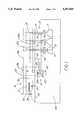
- FIG. 1is a pictorial schematic circuit diagram of a bilevel lighting system incorporating inventive features.
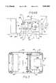
- FIG. 2is a perspective view of a high bay lighting fixture, an exemplary type of fixture useful with the system of FIG. 1.
- FIG. 3is a top plan view of a portion of the housing shown in FIG. 2 taken along the viewing plane 3--3 thereof.
- FIG. 4is a perspective view of a floodlight lighting fixture, another exemplary type of fixture useful with the system of FIG. 1.
- FIG. 5is a view of the floodlight housing shown in FIG. 4 taken along the viewing axis VA5 thereof with cover, reflector and lamp removed.
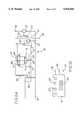
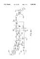
- FIG. 6Ais a schematic circuit diagram of the control device of the system of FIG. 1 shown in conjunction with a ballast and a lamp. The diagram applies to systems used with metal halide lamps.
- FIG. 6Bis a schematic circuit diagram of the control device of the system of FIG. 1 shown in conjunction with a ballast, an igniter and a lamp. The diagram applies to systems used with high pressure sodium lamps.
- FIG. 7is a simplified diagram of the relay portion of the control device of FIG. 6.
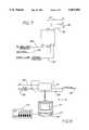
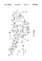
- FIG. 8Ais a schematic circuit diagram of one embodiment of the relay portion shown in FIG. 7 as applied to systems used with metal halide lamps.
- FIG. 8Bis a schematic circuit diagram of another embodiment of the relay portion shown in FIG. 7 as applied to systems used with high pressure sodium lamps.
- FIG. 9is a pictorial schematic diagram of a control module of the occupancy-sensing type.
- FIG. 10is a pictorial schematic diagram of a control module of the timekeeping type.
- FIG. 11is a composite pictorial diagram illustrating a control module interfaced with a photocell and/or an energy management system.
- the inventioninvolves a unique lighting system 10 of the type generally referred to as a bilevel lighting system.
- Systems of this typeprovide two different levels of illumination, depending upon the level of electrical power consumed by the system lighting fixtures 11.
- the inventionis particularly well suited for fixtures 11 equipped with lamps 13 of the high intensity discharge (HID) type, e.g., mercury, metal halide (MH) or high pressure sodium (HPS) lamps.
- HIDhigh intensity discharge
- MHmetal halide
- HPShigh pressure sodium
- the system 10 of FIG. 1is supplied by an electrical distribution network 15 with an exemplary three-phase transformer having a wye-connected winding 17 at its output side.
- Such winding 17has A, B and C phases 19, 21 and 23, respectively, a grounded neutral 25, a ground lead 27 and a common lead 29 extending from the neutral 25.
- Exemplary phase-to-neutral voltagesmay be 120 V, 277 V, 347 V (all at 60 Hz) or 230 V at 50 Hz. (It is to be appreciated that the new fixtures 11 and systems 10 using such fixtures 11 need not be applied exclusively to polyphase distribution networks. They are equally applicable to single phase networks.)
- Each of a plurality of lighting fixtures 11is connected to phase lines 19a, 21a, 23a of the distribution network 15 by a phase input lead 31, a common input lead 33 and a ground input lead 35. It should be appreciated that each of the three illustrated fixtures 11 has its phase input lead 31 connected to a different phase line 19a, 21a, 23a and, thus, to a different phase 19, 21, 23 of the winding 17. This is not a requirement of the inventive system 10 in which fixtures 11 can be connected randomly to phase lines 19a, 21a, 23a. Rather, FIG. 1 merely illustrates the accepted practice of approximately balancing the load imposed upon each phase of a transformer.
- a disconnect panel 37Interposed between the winding 17 and the fixtures 11 is a disconnect panel 37 having one pole of a switching mechanism 39, e.g., a circuit breaker, in series with each phase line 19a, 21a, 23a.
- the mechanism 39is opened to disconnect all power from the fixtures 11 and closed when illumination (whether high or low level) is desired.
- the system 10also includes a control module 41 having a common lead 43 connected to the common lead 29 of the distribution network 15. There is also one lead 45 connected to a phase line on the load side of the mechanism 39 (e.g., connected to line 23a in the drawing) for providing voltage to the module power pack 47, the latter used only for a sensor-controlled system 10. (The particular phase line 19a, 21a, 23a selected for the purpose is usually immaterial since the control module 41 consumes very little power.)
- a single control wire 49extends between each fixture 11 and the module 41 and as described in more detail below, such wire 49 is used to control the level of electrical power consumed by each fixture 11. All fixtures 11 connected to a particular module 41 are controlled in unison and will operate at the same power level, i.e., high or low.
- two or more such systems 10are often employed to illuminate a particular area, especially a larger area such as a warehouse.
- Each such system 10is independently controlled by its own control module 41 and can be used to provide bilevel illumination within any one of several smaller "zones" where people may be working within the larger area.
- the inventionis particularly advantageous where persons are moving from zone to zone--the installation can be configured and controlled so that only the occupied zone is illuminated.
- FIGS. 2, 3, 4 and 5show aspects of standard fixture housings made by Ruud Lighting, Inc., Racine, Wis., the leading manufacturer of industrial and commercial lighting fixtures and the assignee of the invention.
- FIGS. 2 and 3depict what is known as a high bay fixture 11.
- Such fixture 11includes the main housing 51, a neck housing 53 and a reflector 55 attached to and suspended from the neck housing 53.
- the main housing 51has two identical housing portions, namely, an upper portion 57a inverted atop the lower portion 57b to define an enclosed space.
- a conventional ballast 59is installed in the cell 61 and, in a non-bilevel fixture, a single capacitor is installed in the cell 63.
- cell 63has a control device 65 which includes a relay 67 bracket-mounted adjacent to a dual capacitor 69, i.e., two separate capacitors 71, 73 having one common terminal 75 and assembled within a cylinder-like common container 77.
- the dual capacitor 69is much more convenient to use than two separate capacitors as used in known systems.
- the capacitor 71also identified as C1
- the capacitor 73also identified as C2
- the capacitor 71is 24 microfarads
- the capacitor 73is 38 microfarads.
- other capacitor combinationsmay be used with other lamp wattages and other types of lamps, e.g., mercury vapor lamps.
- the housing 83 shown in FIGS. 4 and 5is used for floodlights.
- a conventional ballast 59is installed in the cell 85 and, in a non-bilevel fixture, a single capacitor is installed in the cell 87.
- the cell 87has a control device 65 which, as with the portion 57b of FIG. 3, includes a relay 67 bracket-mounted adjacent to a dual capacitor 69.
- the exterior arrangement of the relay 67is shown generally in FIG. 7 and the relay internal circuits 79, 81 (for metal halide and high pressure sodium lamps, respectively) are shown in FIGS. 8A and 8B, respectively.
- line 89is connected to the ballast primary 91, line 93 to common 29 of the supply, line 95 to capacitor terminal 82, line 97 to capacitor terminal 84 and (in the circuit 79 of FIG. 8A for metal halide lamps) line 99 to the lamp 13.
- the control conductor 101is connected to the control wire 49 and is used for relay switching as described below.
- the circuit of FIG. 8B(for high pressure sodium lamps) has no line corresponding to line 99 and such omission should be appreciated when considering FIG. 7.
- the relay 67is of the solid state type having a pair of silicon-controlled rectifiers 103 which can be switched between a conducting and a non-conducting state.
- the new system 10involves using two capacitors 71, 73 with a particular fixture lamp 13. As is apparent from an inspection of FIGS. 6A or 6B, when the relay 67 is in a conducting state, the capacitors 71, 73 are connected in parallel and the power consumed by the lamp 13 is at rated value. When the relay 67 is in a non-conducting state, capacitor 71 is disconnected from the lamp circuit.
- the single electrical control conductor 101is attached to the control device 65, extends from the housing 51 or 83 and is coupled to the control wire 49 of the module 41 for remotely controlling the voltage applied to the relay 67 via conductor 101.
- the relay 67controls the power consumed by the fixture 11.
- the relay 67is of the random crossing type. That is, the relay 67 is switched without regard for the instantaneous value of AC voltage across its switched or output terminals.
- the arrangement depicted in the Carl patentuses a zero crossing relay. Insofar as is known, a random crossing relay 67 in a bilevel lighting system is new.
- control device 65also includes an inductor 109 or "choke,” a terminal of which is connected to the capacitor 73.
- inductor 109attenuates voltage “spikes” that can occur when the relay 67 is switched; voltage attenuation has the effect of limiting relay surge current.
- Capacitorsare electrical energy storage devices and over time (and when used in the inventive system 10) such capacitors tend to lose their stored energy or "charge.” However, if the system 10 is switched rather rapidly between high and low power modes, there may not be time for capacitor stored energy to dissipate. Therefore, it is advisable to equip at least one capacitor (capacitor 71) with a bleed resistor 111 connected in parallel therewith for more quickly dissipating energy stored in such capacitor 71. This arrangement enhances reliability.
- an ignitor 113is included and functions as a bleed resistor with respect to the capacitor 73. Therefore, only a single bleed resistor 111 is used and it is connected across capacitor 71. On the other hand, when the circuit is used with an MH lamp, no ignitor is used. In that instance, a second bleed resistor 115 is connected across capacitor 73.
- one embodiment of the control module 41has a passive infrared sensor panel 117 which scans substantially continuously and detects changes in infrared heat radiated within the area 118 being monitored. For example, if a human enters such area 118, the panel 117 detects body heat. When heat is detected, the control module 41 causes the binary signal to be high and voltage (preferably in the range of 100-380 VAC) is applied to the control wire 49 and, therefore, to each fixture 11 connected to that module 41. The fixtures 11 are thereby brought to their rated power and illumination levels.
- an ultrasonic sensorcan be used.
- a six-position DIP switch 119is provided to permit introducing a time delay between the time at which a change in heat is last detected and the time at which the fixtures 11 are returned to their low power level.
- time delayis adjustable between a few seconds and about 30 minutes. To put it another way, the time delay maintains the fixtures 11 at rated power for anywhere from a few seconds to 30 minutes after the last scan on which a person is detected.
- the sensor module 41also has an ambient light level adjustment 121 and a sensitivity adjustment 123.
- the formercan be used to prevent fixtures 11 controlled by that module 41 from being switched to full power if natural light levels are above a user-specified level. In a specific embodiment, this level is adjustable from about 2.5 to over 400 footcandles. Significantly, no wiring changes are required to utilize this function.
- An override switch 129is manually operable to bring the fixture(s) 11 to full power on demand.
- control module 41may also be of the "timekeeping" type which causes the system 10 to switch between power modes at predetermined times and/or during predetermined days of the week.
- the module 41 of FIG. 10has a display panel 125 and buttons 127 or the like for programming the module 41 for the time period(s) during which the fixtures 11 will be at rated power and provide rated illumination.
- FIG. 11shows how the module 41 may be used with a photocell 131 and/or an energy management system 133 as mentioned above.
- the photocell 131is that device used to detect an ambient light level while the energy management system 133 is computerized for illumination, HVAC control, security and other functions. Photocells and energy management systems, per se, are known.
- the inventionalso involves a method for controlling two levels of power to a system 10 illuminating an area.
- the methodincluding the steps of connecting an electrical conductor 101 between the control module 41 and the fixture 11 and changing the state of the binary signal on the conductor 101.
- the control module 41is of the occupancy-sensing type (as shown in FIG. 9) and the state-changing step is preceded by the step of detecting an occupant within the area 118.
- control module 41keeps actual time and has at least one setpoint time entered therein.
- the state of the conductor 101 binary signalis changed when the actual time is coincident with the setpoint time.
- the distribution network 15provides sinusoidal AC voltage and the fixture 11 includes the relay 67 shown in FIGS. 6-8 which is switched between a non-conducting state and a conducting state.
- the state-changing stepis followed by the step of changing the state of the relay 67 independently of the instantaneous value of the voltage at the switched relay terminals.
- timing circuitry which causes such rated power startingis incorporated into the fixture-mounted relay 67 rather than into a remotely mounted, multi-fixture "master" timing circuit as with prior art arrangements.
- the inventive arrangementprovides a subtle but very important advantage.
- the timing circuit 135is shown in FIGS. 8A and 8B and includes the capacitor C5, initially at zero charge. While the capacitor C5 is charging, the output pin of U1B is effectively grounded, the optocoupler conducts and the fixture is operated at rated power.
- the rate at which the capacitor C5 chargesis governed by the resistor R3 and a value is selected so that the charging time is about 8-14 minutes.
Landscapes
- Circuit Arrangement For Electric Light Sources In General (AREA)
Abstract
Description
______________________________________ COMPONENT VALUE/TYPE ______________________________________ R1 510 C1, C2, C3 047 mf D1, D2, D3, D4, D6, D7 1N4007 D8, D9, D10 AND D11 R11, R5 10K R8 2.2K D5 1N4762 C4 22 mf R6 6.2K R3 1M R7 1K C5 220 mf R10 100 R2 330K C6 .1 mf R4 560K ______________________________________
______________________________________ COMPONENT VALUE/TYPE ______________________________________ R1 510 C1, C2, C3, C7 AND C9 0.47 mf D1, D2, D3, D4, D6, 1N4007 D7, D8, D9, D10, D11, D12 AND D13 D5 1N4762 C4 22 mf R11 10K R12 10K R8 2.2K R10 100 R6 6.2K R3 1.2M R7 1K C5 220 mf R13 27K R2, R18 AND R19 330K C6 .1 mf R14 4.7M R15 550K R16 1M C8 4.7 mf R17 4.7M C10 22 mf ______________________________________
Claims (13)
Priority Applications (3)
| Application Number | Priority Date | Filing Date | Title |
|---|---|---|---|
| US08/231,181US5451843A (en) | 1994-04-22 | 1994-04-22 | Apparatus and method for providing bilevel illumination |
| NZ264961ANZ264961A (en) | 1994-04-22 | 1994-11-21 | Lighting with remote binary power level control |
| AU81509/94AAU673641B2 (en) | 1994-04-22 | 1994-12-16 | Improved apparatus and method for providing bilevel illumination |
Applications Claiming Priority (1)
| Application Number | Priority Date | Filing Date | Title |
|---|---|---|---|
| US08/231,181US5451843A (en) | 1994-04-22 | 1994-04-22 | Apparatus and method for providing bilevel illumination |
Publications (1)
| Publication Number | Publication Date |
|---|---|
| US5451843Atrue US5451843A (en) | 1995-09-19 |
Family
ID=22868079
Family Applications (1)
| Application Number | Title | Priority Date | Filing Date |
|---|---|---|---|
| US08/231,181Expired - Fee RelatedUS5451843A (en) | 1994-04-22 | 1994-04-22 | Apparatus and method for providing bilevel illumination |
Country Status (3)
| Country | Link |
|---|---|
| US (1) | US5451843A (en) |
| AU (1) | AU673641B2 (en) |
| NZ (1) | NZ264961A (en) |
Cited By (37)
| Publication number | Priority date | Publication date | Assignee | Title |
|---|---|---|---|---|
| US5633540A (en)* | 1996-06-25 | 1997-05-27 | Lutron Electronics Co., Inc. | Surge-resistant relay switching circuit |
| US5637964A (en)* | 1995-03-21 | 1997-06-10 | Lutron Electronics Co., Inc. | Remote control system for individual control of spaced lighting fixtures |
| US5987205A (en)* | 1996-09-13 | 1999-11-16 | Lutron Electronics Co., Inc. | Infrared energy transmissive member and radiation receiver |
| US6000810A (en)* | 1998-03-10 | 1999-12-14 | Eagle Energy Systems, Ltd. | Low voltage storage warehouse lighting system |
| US6031340A (en)* | 1998-07-31 | 2000-02-29 | Magnetek, Inc. | Device and method for capacitive bi-level switching of high intensity discharge lighting |
| US6037721A (en)* | 1996-01-11 | 2000-03-14 | Lutron Electronics, Co., Inc. | System for individual and remote control of spaced lighting fixtures |
| US6305602B1 (en) | 1997-12-01 | 2001-10-23 | Diebold, Incorporated | Light monitoring system and method for automated transaction machine |
| US6393608B1 (en) | 2000-11-16 | 2002-05-28 | William Miles Pulford | Self-powered modification kit for hid luminaire installations |
| US6545429B1 (en)* | 2000-06-08 | 2003-04-08 | Hubbell Incorporated | Lighting assembly having regulating transformer distally located from ballast |
| US6563255B1 (en) | 2000-10-19 | 2003-05-13 | General Electric Company | Luminaire incorporating arc tube preheater |
| US6597133B2 (en) | 2001-08-31 | 2003-07-22 | Hubbell Incorporated | Two-wire lighting control system with indicator for imminent time out period expiration |
| US6856101B1 (en)* | 2002-07-24 | 2005-02-15 | Acuity Brands, Inc. | Method and apparatus for switching of parallel capacitors in an HID bi-level dimming system using voltage suppression |
| US6940230B2 (en)* | 2002-05-30 | 2005-09-06 | Hubbell Incorporated | Modular lamp controller |
| US20070043541A1 (en)* | 2005-06-30 | 2007-02-22 | Cleland Donald A | Method and system for controling a luminaire |
| US20070040513A1 (en)* | 2005-06-30 | 2007-02-22 | Cleland Donald A | Method and system for luminance characterization |
| US20090066540A1 (en)* | 2007-09-07 | 2009-03-12 | Dimitri Marinakis | Centralized route calculation for a multi-hop streetlight network |
| US20090066258A1 (en)* | 2007-09-07 | 2009-03-12 | Streetlight Intelligence, Inc. | Streelight monitoring and control |
| US20090230887A1 (en)* | 2008-03-13 | 2009-09-17 | Wei Xiong | Electronic ballast for a gas discharge lamp with controlled filament heating during dimming |
| US20090261735A1 (en)* | 2008-04-17 | 2009-10-22 | Heathco Llc | Lighting System to Facilitate Remote Modification of a Light Fixture Modifiable Operating Parameter |
| US20100070099A1 (en)* | 2008-09-15 | 2010-03-18 | General Electric Company | Demand side management module |
| US20100207728A1 (en)* | 2009-02-18 | 2010-08-19 | General Electric Corporation | Energy management |
| US20100301781A1 (en)* | 2006-11-15 | 2010-12-02 | Budike Jr Lothar E S | Modular wireless lighting control system using a common ballast control interface |
| US20110061177A1 (en)* | 2009-09-15 | 2011-03-17 | General Electric Company | Clothes washer demand response with at least one additional spin cycle |
| US20110061176A1 (en)* | 2009-09-15 | 2011-03-17 | General Electric Company | Clothes washer demand response by duty cycling the heater and/or the mechanical action |
| US20110062142A1 (en)* | 2008-09-15 | 2011-03-17 | General Electric Company | Load shedding for surface heating units on electromechanically controlled cooking appliances |
| US20110061175A1 (en)* | 2009-09-15 | 2011-03-17 | General Electric Company | Clothes washer demand response with dual wattage or auxiliary heater |
| US20110095017A1 (en)* | 2008-09-15 | 2011-04-28 | General Electric Company | System for reduced peak power consumption by a cooking appliance |
| US20110114627A1 (en)* | 2008-09-15 | 2011-05-19 | General Electric Company | System and method for minimizing consumer impact during demand responses |
| US20120217899A1 (en)* | 2011-02-25 | 2012-08-30 | Toshiba Lighting & Technology Corporation | Lighting device and luminaire |
| US8433426B2 (en) | 2005-06-30 | 2013-04-30 | Led Roadway Lighting Ltd | Adaptive energy performance monitoring and control system |
| US8801862B2 (en) | 2010-09-27 | 2014-08-12 | General Electric Company | Dishwasher auto hot start and DSM |
| US8943845B2 (en) | 2009-09-15 | 2015-02-03 | General Electric Company | Window air conditioner demand supply management response |
| US20150296586A1 (en)* | 2011-03-31 | 2015-10-15 | Litonics Limited | Lighting device |
| US9303878B2 (en) | 2008-09-15 | 2016-04-05 | General Electric Company | Hybrid range and method of use thereof |
| US9357609B2 (en) | 2011-03-31 | 2016-05-31 | Litonics Limited | Lighting device |
| US9363871B2 (en) | 2012-05-04 | 2016-06-07 | Litonics Limited | Lighting device |
| US9525306B1 (en)* | 2013-03-13 | 2016-12-20 | Cooper Technologies Company | Automatic emergency lighting load control |
Citations (15)
| Publication number | Priority date | Publication date | Assignee | Title |
|---|---|---|---|---|
| US3433887A (en)* | 1966-06-06 | 1969-03-18 | Thomas Industries Inc | Lighting fixture with quickly removable ballast assembly |
| US3872350A (en)* | 1973-03-20 | 1975-03-18 | Gen Electric | Ballast having integral time delay relay |
| US3919459A (en)* | 1975-02-04 | 1975-11-11 | Westinghouse Electric Corp | Luminaire ballast mounting system |
| US4000406A (en)* | 1974-11-29 | 1976-12-28 | Esquire, Inc. | Light fixture |
| US4054790A (en)* | 1976-05-17 | 1977-10-18 | Esquire, Inc. | Light fixture |
| US4144462A (en)* | 1977-04-28 | 1979-03-13 | Dual-Lite, Inc. | Emergency lighting fluorescent pack |
| US4147962A (en)* | 1977-12-19 | 1979-04-03 | Westinghouse Electric Corp. | Energy-conserving illumination system |
| US4258293A (en)* | 1978-08-11 | 1981-03-24 | Cosmos Energy Innovation S.A. | High intensity discharge lighting system |
| US4344071A (en)* | 1980-07-10 | 1982-08-10 | Roger A. Heller | Light switching mechanism |
| US4431948A (en)* | 1982-08-09 | 1984-02-14 | Standun Controls, Inc. | Apparatus for control of load power consumption |
| US4739188A (en)* | 1986-06-23 | 1988-04-19 | Fl Industries, Inc. | Starting circuit enclosure |
| US4873469A (en)* | 1987-05-21 | 1989-10-10 | Pittway Corporation | Infrared actuated control switch assembly |
| US4931701A (en)* | 1988-07-06 | 1990-06-05 | Wide-Lite International Corporation | Bi-level ballast circuit for operating HID lamps |
| US5050042A (en)* | 1990-08-08 | 1991-09-17 | Emerson Electric Co. | Housing assembly for electrical components with window for viewing electrical components, sealing rings, and sleeves accepting different sizes of conduit |
| US5138528A (en)* | 1991-02-06 | 1992-08-11 | Amp Incorporated | Electrical packaging system and components therefor |
- 1994
- 1994-04-22USUS08/231,181patent/US5451843A/ennot_activeExpired - Fee Related
- 1994-11-21NZNZ264961Apatent/NZ264961A/enunknown
- 1994-12-16AUAU81509/94Apatent/AU673641B2/ennot_activeCeased
Patent Citations (15)
| Publication number | Priority date | Publication date | Assignee | Title |
|---|---|---|---|---|
| US3433887A (en)* | 1966-06-06 | 1969-03-18 | Thomas Industries Inc | Lighting fixture with quickly removable ballast assembly |
| US3872350A (en)* | 1973-03-20 | 1975-03-18 | Gen Electric | Ballast having integral time delay relay |
| US4000406A (en)* | 1974-11-29 | 1976-12-28 | Esquire, Inc. | Light fixture |
| US3919459A (en)* | 1975-02-04 | 1975-11-11 | Westinghouse Electric Corp | Luminaire ballast mounting system |
| US4054790A (en)* | 1976-05-17 | 1977-10-18 | Esquire, Inc. | Light fixture |
| US4144462A (en)* | 1977-04-28 | 1979-03-13 | Dual-Lite, Inc. | Emergency lighting fluorescent pack |
| US4147962A (en)* | 1977-12-19 | 1979-04-03 | Westinghouse Electric Corp. | Energy-conserving illumination system |
| US4258293A (en)* | 1978-08-11 | 1981-03-24 | Cosmos Energy Innovation S.A. | High intensity discharge lighting system |
| US4344071A (en)* | 1980-07-10 | 1982-08-10 | Roger A. Heller | Light switching mechanism |
| US4431948A (en)* | 1982-08-09 | 1984-02-14 | Standun Controls, Inc. | Apparatus for control of load power consumption |
| US4739188A (en)* | 1986-06-23 | 1988-04-19 | Fl Industries, Inc. | Starting circuit enclosure |
| US4873469A (en)* | 1987-05-21 | 1989-10-10 | Pittway Corporation | Infrared actuated control switch assembly |
| US4931701A (en)* | 1988-07-06 | 1990-06-05 | Wide-Lite International Corporation | Bi-level ballast circuit for operating HID lamps |
| US5050042A (en)* | 1990-08-08 | 1991-09-17 | Emerson Electric Co. | Housing assembly for electrical components with window for viewing electrical components, sealing rings, and sleeves accepting different sizes of conduit |
| US5138528A (en)* | 1991-02-06 | 1992-08-11 | Amp Incorporated | Electrical packaging system and components therefor |
Non-Patent Citations (12)
| Title |
|---|
| Hi/Lo Lighting Systems by Day Brite/Benjamin Thomas Industries, Inc. 8 pages Feb., 1992.* |
| Hi/Lo Lighting Systems by Day-Brite/Benjamin Thomas Industries, Inc.-8 pages -Feb., 1992. |
| The Watt Soptter CI Passive Infrared Sensor 4 pages Jun., 1993.* |
| The Watt Soptter-CI Passive Infrared Sensor-4 pages -Jun., 1993. |
| Wide Light Buyers Guide Specification Grade HID Lighting and Controls 15 pages Sep. 1988.* |
| Wide Lite Bi Level Lighting Control 15 pages Jan. 1989.* |
| Wide Lite Spectra Lyte High Performance Lighting for Parking Garages 12 pages May, 1990.* |
| Wide Lite Zone Mate HID Dimming/Bi Level Switching Design Manual 21 pages Apr., 1986.* |
| Wide-Light Buyers Guide Specification-Grade HID Lighting and Controls-15 pages -Sep. 1988. |
| Wide-Lite Bi-Level Lighting Control-15 pages -Jan. 1989. |
| Wide-Lite Spectra-Lyte High Performance Lighting for Parking Garages-12 pages -May, 1990. |
| Wide-Lite Zone Mate HID Dimming/Bi-Level Switching Design Manual-21 pages -Apr., 1986. |
Cited By (81)
| Publication number | Priority date | Publication date | Assignee | Title |
|---|---|---|---|---|
| US5637964A (en)* | 1995-03-21 | 1997-06-10 | Lutron Electronics Co., Inc. | Remote control system for individual control of spaced lighting fixtures |
| US6037721A (en)* | 1996-01-11 | 2000-03-14 | Lutron Electronics, Co., Inc. | System for individual and remote control of spaced lighting fixtures |
| US6310440B1 (en) | 1996-01-11 | 2001-10-30 | Lutron Electronics Company, Inc. | System for individual and remote control of spaced lighting fixtures |
| US5633540A (en)* | 1996-06-25 | 1997-05-27 | Lutron Electronics Co., Inc. | Surge-resistant relay switching circuit |
| US5987205A (en)* | 1996-09-13 | 1999-11-16 | Lutron Electronics Co., Inc. | Infrared energy transmissive member and radiation receiver |
| US6305602B1 (en) | 1997-12-01 | 2001-10-23 | Diebold, Incorporated | Light monitoring system and method for automated transaction machine |
| US6000810A (en)* | 1998-03-10 | 1999-12-14 | Eagle Energy Systems, Ltd. | Low voltage storage warehouse lighting system |
| US6031340A (en)* | 1998-07-31 | 2000-02-29 | Magnetek, Inc. | Device and method for capacitive bi-level switching of high intensity discharge lighting |
| US6545429B1 (en)* | 2000-06-08 | 2003-04-08 | Hubbell Incorporated | Lighting assembly having regulating transformer distally located from ballast |
| US6563255B1 (en) | 2000-10-19 | 2003-05-13 | General Electric Company | Luminaire incorporating arc tube preheater |
| US6393608B1 (en) | 2000-11-16 | 2002-05-28 | William Miles Pulford | Self-powered modification kit for hid luminaire installations |
| US6597133B2 (en) | 2001-08-31 | 2003-07-22 | Hubbell Incorporated | Two-wire lighting control system with indicator for imminent time out period expiration |
| US6940230B2 (en)* | 2002-05-30 | 2005-09-06 | Hubbell Incorporated | Modular lamp controller |
| US6856101B1 (en)* | 2002-07-24 | 2005-02-15 | Acuity Brands, Inc. | Method and apparatus for switching of parallel capacitors in an HID bi-level dimming system using voltage suppression |
| US20070043541A1 (en)* | 2005-06-30 | 2007-02-22 | Cleland Donald A | Method and system for controling a luminaire |
| US20070040513A1 (en)* | 2005-06-30 | 2007-02-22 | Cleland Donald A | Method and system for luminance characterization |
| US7429828B2 (en) | 2005-06-30 | 2008-09-30 | Streetlight Intelligence, Inc. | Method and system for luminance characterization |
| US20090001893A1 (en)* | 2005-06-30 | 2009-01-01 | Streetlight Intelligence, Inc. | Method and system for luminance characterization |
| US20110057570A1 (en)* | 2005-06-30 | 2011-03-10 | Streetlight Intelligence, Inc. | Method and System for Luminance Characterization |
| US7734356B2 (en) | 2005-06-30 | 2010-06-08 | Streetlight Intelligence, Inc. | Method and system for controlling a luminaire |
| US7834555B2 (en) | 2005-06-30 | 2010-11-16 | Streetlight Intelligence, Inc. | Method and system for luminance characterization |
| US8264156B2 (en) | 2005-06-30 | 2012-09-11 | Led Roadway Lighting Ltd. | Method and system for luminance characterization |
| US9144135B2 (en) | 2005-06-30 | 2015-09-22 | Led Roadway Lighting Ltd. | Adaptive energy performance monitoring and control system |
| US8433426B2 (en) | 2005-06-30 | 2013-04-30 | Led Roadway Lighting Ltd | Adaptive energy performance monitoring and control system |
| US8110996B2 (en)* | 2006-11-15 | 2012-02-07 | Budike Jr Lothar E S | Modular wireless lighting control system using a common ballast control interface |
| US20100301781A1 (en)* | 2006-11-15 | 2010-12-02 | Budike Jr Lothar E S | Modular wireless lighting control system using a common ballast control interface |
| US8570190B2 (en) | 2007-09-07 | 2013-10-29 | Led Roadway Lighting Ltd. | Centralized route calculation for a multi-hop streetlight network |
| US8694256B2 (en) | 2007-09-07 | 2014-04-08 | Led Roadway Lighting Ltd. | Streetlight monitoring and control |
| US8290710B2 (en) | 2007-09-07 | 2012-10-16 | Led Roadway Lighting Ltd. | Streetlight monitoring and control |
| US20090066258A1 (en)* | 2007-09-07 | 2009-03-12 | Streetlight Intelligence, Inc. | Streelight monitoring and control |
| US20090066540A1 (en)* | 2007-09-07 | 2009-03-12 | Dimitri Marinakis | Centralized route calculation for a multi-hop streetlight network |
| US20090230887A1 (en)* | 2008-03-13 | 2009-09-17 | Wei Xiong | Electronic ballast for a gas discharge lamp with controlled filament heating during dimming |
| US7952303B2 (en)* | 2008-03-13 | 2011-05-31 | Universal Lighting Technologies, Inc. | Electronic ballast for a gas discharge lamp with controlled filament heating during dimming |
| US20090261735A1 (en)* | 2008-04-17 | 2009-10-22 | Heathco Llc | Lighting System to Facilitate Remote Modification of a Light Fixture Modifiable Operating Parameter |
| US7880394B2 (en)* | 2008-04-17 | 2011-02-01 | Heathco Llc | Lighting system to facilitate remote modification of a light fixture modifiable operating parameter |
| US8617316B2 (en) | 2008-09-15 | 2013-12-31 | General Electric Company | Energy management of dishwasher appliance |
| US20100092625A1 (en)* | 2008-09-15 | 2010-04-15 | General Electric Company | Energy management of household appliances |
| US20100187219A1 (en)* | 2008-09-15 | 2010-07-29 | General Electric Company | Energy management of household appliances |
| US20100175719A1 (en)* | 2008-09-15 | 2010-07-15 | General Electric Company | Energy management of dishwasher appliance |
| US20100179708A1 (en)* | 2008-09-15 | 2010-07-15 | General Electric Company | Energy management of household appliances |
| US9303878B2 (en) | 2008-09-15 | 2016-04-05 | General Electric Company | Hybrid range and method of use thereof |
| US20100070099A1 (en)* | 2008-09-15 | 2010-03-18 | General Electric Company | Demand side management module |
| US20110062142A1 (en)* | 2008-09-15 | 2011-03-17 | General Electric Company | Load shedding for surface heating units on electromechanically controlled cooking appliances |
| US8843242B2 (en) | 2008-09-15 | 2014-09-23 | General Electric Company | System and method for minimizing consumer impact during demand responses |
| US20110095017A1 (en)* | 2008-09-15 | 2011-04-28 | General Electric Company | System for reduced peak power consumption by a cooking appliance |
| US20110114627A1 (en)* | 2008-09-15 | 2011-05-19 | General Electric Company | System and method for minimizing consumer impact during demand responses |
| US20100146712A1 (en)* | 2008-09-15 | 2010-06-17 | General Electric Company | Energy management of clothes washer appliance |
| US20100121499A1 (en)* | 2008-09-15 | 2010-05-13 | General Electric Company | Management control of household appliances using continuous tone-coded dsm signalling |
| US8803040B2 (en) | 2008-09-15 | 2014-08-12 | General Electric Company | Load shedding for surface heating units on electromechanically controlled cooking appliances |
| US20100101254A1 (en)* | 2008-09-15 | 2010-04-29 | General Electric Company | Energy management of household appliances |
| US20100094470A1 (en)* | 2008-09-15 | 2010-04-15 | General Electric Company | Demand side management of household appliances beyond electrical |
| US8355826B2 (en) | 2008-09-15 | 2013-01-15 | General Electric Company | Demand side management module |
| US8367984B2 (en) | 2008-09-15 | 2013-02-05 | General Electric Company | Energy management of household appliances |
| US20100089909A1 (en)* | 2008-09-15 | 2010-04-15 | General Electric Company | Energy management of household appliances |
| US8474279B2 (en) | 2008-09-15 | 2013-07-02 | General Electric Company | Energy management of household appliances |
| US8793021B2 (en) | 2008-09-15 | 2014-07-29 | General Electric Company | Energy management of household appliances |
| US8541719B2 (en) | 2008-09-15 | 2013-09-24 | General Electric Company | System for reduced peak power consumption by a cooking appliance |
| US8548635B2 (en) | 2008-09-15 | 2013-10-01 | General Electric Company | Energy management of household appliances |
| US8730018B2 (en) | 2008-09-15 | 2014-05-20 | General Electric Company | Management control of household appliances using continuous tone-coded DSM signalling |
| US8618452B2 (en) | 2008-09-15 | 2013-12-31 | General Electric Company | Energy management of household appliances |
| US20100090806A1 (en)* | 2008-09-15 | 2010-04-15 | General Electric Company | Management control of household appliances using rfid communication |
| US8626347B2 (en) | 2008-09-15 | 2014-01-07 | General Electric Company | Demand side management module |
| US8627689B2 (en) | 2008-09-15 | 2014-01-14 | General Electric Company | Energy management of clothes washer appliance |
| US8704639B2 (en) | 2008-09-15 | 2014-04-22 | General Electric Company | Management control of household appliances using RFID communication |
| US20100070091A1 (en)* | 2008-09-15 | 2010-03-18 | General Electric Company | Energy management of household appliances |
| US20100207728A1 (en)* | 2009-02-18 | 2010-08-19 | General Electric Corporation | Energy management |
| US20110061177A1 (en)* | 2009-09-15 | 2011-03-17 | General Electric Company | Clothes washer demand response with at least one additional spin cycle |
| US8943845B2 (en) | 2009-09-15 | 2015-02-03 | General Electric Company | Window air conditioner demand supply management response |
| US20110061176A1 (en)* | 2009-09-15 | 2011-03-17 | General Electric Company | Clothes washer demand response by duty cycling the heater and/or the mechanical action |
| US8943857B2 (en) | 2009-09-15 | 2015-02-03 | General Electric Company | Clothes washer demand response by duty cycling the heater and/or the mechanical action |
| US20110061175A1 (en)* | 2009-09-15 | 2011-03-17 | General Electric Company | Clothes washer demand response with dual wattage or auxiliary heater |
| US8869569B2 (en) | 2009-09-15 | 2014-10-28 | General Electric Company | Clothes washer demand response with at least one additional spin cycle |
| US8522579B2 (en) | 2009-09-15 | 2013-09-03 | General Electric Company | Clothes washer demand response with dual wattage or auxiliary heater |
| US8801862B2 (en) | 2010-09-27 | 2014-08-12 | General Electric Company | Dishwasher auto hot start and DSM |
| US20120217899A1 (en)* | 2011-02-25 | 2012-08-30 | Toshiba Lighting & Technology Corporation | Lighting device and luminaire |
| US8643307B2 (en)* | 2011-02-25 | 2014-02-04 | Toshiba Lighting & Technology Corporation | Lighting device and luminaire |
| US9307599B2 (en)* | 2011-03-31 | 2016-04-05 | Litonics Limited | Lighting device |
| US20150296586A1 (en)* | 2011-03-31 | 2015-10-15 | Litonics Limited | Lighting device |
| US9357609B2 (en) | 2011-03-31 | 2016-05-31 | Litonics Limited | Lighting device |
| US9363871B2 (en) | 2012-05-04 | 2016-06-07 | Litonics Limited | Lighting device |
| US9525306B1 (en)* | 2013-03-13 | 2016-12-20 | Cooper Technologies Company | Automatic emergency lighting load control |
Also Published As
| Publication number | Publication date |
|---|---|
| AU673641B2 (en) | 1996-11-14 |
| AU8150994A (en) | 1995-11-02 |
| NZ264961A (en) | 1998-01-26 |
Similar Documents
| Publication | Publication Date | Title |
|---|---|---|
| US5451843A (en) | Apparatus and method for providing bilevel illumination | |
| EP0613328B1 (en) | Bi-level lighting control system for HID lamps | |
| EP0542425B1 (en) | Step-dimming magnetic regulator for discharge lamps | |
| US6031340A (en) | Device and method for capacitive bi-level switching of high intensity discharge lighting | |
| US6114816A (en) | Lighting control system for discharge lamps | |
| US5450302A (en) | Exterior high intensity discharge illumination system and method for use | |
| AU683188B2 (en) | Fluorescent tube control | |
| EP0447136B1 (en) | A method for automatic switching and control of lighting | |
| US5508589A (en) | Power saving voltage reduction system for high intensity discharge lighting systems | |
| CN100595713C (en) | Improved apparatus and method for hid lamp control | |
| CA2162889A1 (en) | System and method for distributing power to gas discharge lamps | |
| CA1064097A (en) | Apparatus and method for sustaining the operation of hid lamps | |
| US6271635B1 (en) | Dimming system and method for magnetically ballasted gaseous discharge lamps | |
| JP2600595Y2 (en) | Vending machine power supply | |
| RU2813838C1 (en) | Intelligent multi-lamp lighting device with high-pressure sodium lamps using one power supply | |
| JPH0266882A (en) | lighting system | |
| CA1320247C (en) | Back-up electrical system for lamps | |
| US20080048590A1 (en) | Voltage Regulator | |
| JP3312776B2 (en) | Remote monitoring and control system | |
| WO1998020520A1 (en) | Light producing device and control thereof | |
| GB2144002A (en) | Domestic electrical wiring system | |
| EP0868709A1 (en) | Control circuit and switch for controlling electrical devices | |
| JPH11317294A (en) | Lighting control device and lighting device | |
| AU1109601A (en) | Power saving control circuit for supplying power to a load | |
| JPH05258866A (en) | Lighting equipment |
Legal Events
| Date | Code | Title | Description |
|---|---|---|---|
| AS | Assignment | Owner name:RUUD LIGHTING, INC., WISCONSIN Free format text:ASSIGNMENT OF ASSIGNORS INTEREST;ASSIGNORS:KAHN, MICHAEL J.;KOHANSKI, BERNARD;REEL/FRAME:006963/0758;SIGNING DATES FROM 19940405 TO 19940412 | |
| AS | Assignment | Owner name:NATIONAL CITY BANK, OHIO Free format text:COLLATERAL ASSIGNMENT OF PATENTS AND SECURITY AGREEMENT;ASSIGNOR:RUUD LIGHTING, INC.;REEL/FRAME:008995/0460 Effective date:19980102 | |
| FEPP | Fee payment procedure | Free format text:PAT HLDR NO LONGER CLAIMS SMALL ENT STAT AS SMALL BUSINESS (ORIGINAL EVENT CODE: LSM2); ENTITY STATUS OF PATENT OWNER: LARGE ENTITY | |
| FPAY | Fee payment | Year of fee payment:4 | |
| AS | Assignment | Owner name:PNC BANK, NATIONAL ASSOCIATION, AS AGENT, OHIO Free format text:ASSIGNMENT OF ASSIGNORS INTEREST;ASSIGNOR:ADVANCED LIGHTING TECHNOLOGIES, INC.;REEL/FRAME:010238/0231 Effective date:19990521 | |
| AS | Assignment | Owner name:JOHNSON BANK, WISCONSIN Free format text:ASSIGNMENT OF ASSIGNORS INTEREST;ASSIGNOR:RUUD LIGHTING, INC.;REEL/FRAME:012683/0603 Effective date:20011212 Owner name:RUUD LIGHTING, INC., WISCONSIN Free format text:TERMINATION OF ASSIGNMENT;ASSIGNOR:PNC BANK, NATIONAL ASSOCIATION, AS AGENT;REEL/FRAME:012691/0379 Effective date:20011212 | |
| REMI | Maintenance fee reminder mailed | ||
| LAPS | Lapse for failure to pay maintenance fees | ||
| STCH | Information on status: patent discontinuation | Free format text:PATENT EXPIRED DUE TO NONPAYMENT OF MAINTENANCE FEES UNDER 37 CFR 1.362 | |
| FP | Lapsed due to failure to pay maintenance fee | Effective date:20030919 | |
| AS | Assignment | Owner name:RUUD LIGHTING, INC., WISCONSIN Free format text:RELEASE BY SECURED PARTY;ASSIGNOR:JOHNSON BANK;REEL/FRAME:026798/0746 Effective date:20110817 | |
| AS | Assignment | Owner name:FGI WORLDWIDE LLC, NEW YORK Free format text:SECURITY INTEREST;ASSIGNOR:IDEAL INDUSTRIES LIGHTING LLC;REEL/FRAME:064897/0413 Effective date:20230908 |