US5451823A - Vehicular thermoconductive lead frame rectifier assembly - Google Patents
Vehicular thermoconductive lead frame rectifier assemblyDownload PDFInfo
- Publication number
- US5451823A US5451823AUS08/016,504US1650493AUS5451823AUS 5451823 AUS5451823 AUS 5451823AUS 1650493 AUS1650493 AUS 1650493AUS 5451823 AUS5451823 AUS 5451823A
- Authority
- US
- United States
- Prior art keywords
- cooling member
- diode
- assembly
- lead
- rectifier assembly
- Prior art date
- Legal status (The legal status is an assumption and is not a legal conclusion. Google has not performed a legal analysis and makes no representation as to the accuracy of the status listed.)
- Expired - Lifetime
Links
Images


Classifications
- H—ELECTRICITY
- H01—ELECTRIC ELEMENTS
- H01L—SEMICONDUCTOR DEVICES NOT COVERED BY CLASS H10
- H01L25/00—Assemblies consisting of a plurality of semiconductor or other solid state devices
- H01L25/03—Assemblies consisting of a plurality of semiconductor or other solid state devices all the devices being of a type provided for in a single subclass of subclasses H10B, H10D, H10F, H10H, H10K or H10N, e.g. assemblies of rectifier diodes
- H01L25/10—Assemblies consisting of a plurality of semiconductor or other solid state devices all the devices being of a type provided for in a single subclass of subclasses H10B, H10D, H10F, H10H, H10K or H10N, e.g. assemblies of rectifier diodes the devices having separate containers
- H01L25/11—Assemblies consisting of a plurality of semiconductor or other solid state devices all the devices being of a type provided for in a single subclass of subclasses H10B, H10D, H10F, H10H, H10K or H10N, e.g. assemblies of rectifier diodes the devices having separate containers the devices being of a type provided for in subclass H10D
- H01L25/112—Mixed assemblies
- H—ELECTRICITY
- H02—GENERATION; CONVERSION OR DISTRIBUTION OF ELECTRIC POWER
- H02K—DYNAMO-ELECTRIC MACHINES
- H02K11/00—Structural association of dynamo-electric machines with electric components or with devices for shielding, monitoring or protection
- H02K11/04—Structural association of dynamo-electric machines with electric components or with devices for shielding, monitoring or protection for rectification
- H02K11/049—Rectifiers associated with stationary parts, e.g. stator cores
- H02K11/05—Rectifiers associated with casings, enclosures or brackets
- H—ELECTRICITY
- H02—GENERATION; CONVERSION OR DISTRIBUTION OF ELECTRIC POWER
- H02M—APPARATUS FOR CONVERSION BETWEEN AC AND AC, BETWEEN AC AND DC, OR BETWEEN DC AND DC, AND FOR USE WITH MAINS OR SIMILAR POWER SUPPLY SYSTEMS; CONVERSION OF DC OR AC INPUT POWER INTO SURGE OUTPUT POWER; CONTROL OR REGULATION THEREOF
- H02M7/00—Conversion of AC power input into DC power output; Conversion of DC power input into AC power output
- H02M7/003—Constructional details, e.g. physical layout, assembly, wiring or busbar connections
- H—ELECTRICITY
- H01—ELECTRIC ELEMENTS
- H01L—SEMICONDUCTOR DEVICES NOT COVERED BY CLASS H10
- H01L2924/00—Indexing scheme for arrangements or methods for connecting or disconnecting semiconductor or solid-state bodies as covered by H01L24/00
- H01L2924/0001—Technical content checked by a classifier
- H01L2924/0002—Not covered by any one of groups H01L24/00, H01L24/00 and H01L2224/00
Definitions
- This inventionis directed to constructions for rectifier assemblies for engine-driven alternating current generators that can be manually assembled in either a semi-automatic manufacturing operation with minimum error and a high degree of precision, thereby reducing the manufacturing cost of the rectifier assembly.
- Steele et al.presents a method of embedding preformed leads in a wedge block configuration that is inserted in a dovetail receptacle extruded into an aluminum cooling member.
- the preformed leadsare manufactured of a soft metal that is easily deformed in physical shape by ordinary handling. Precautionary steps must be taken to assure the integrity of the preferred configuration when using Steele's technique.
- the diode chipis sandwiched between two larger header plates of square geometry, requiring additional steps to accomplish the centering requirement.
- the Steele et al. techniquealso requires extraneous means to position the diode-header assemblies on the essentially flat surfaces of the cooling-conductive members.
- the cooling of the insulated cooling member in a rectifier assemblyhas been largely dependent on convection or forced air cooling.
- This method of coolingis adequate, provided that the ventilation apertures are kept clean and free of any debris or foreign matter.
- an adhering filmis often deposited on the cooling members and within the walls of the ventilating apertures from emitted engine lubricants. This film attracts and holds botanical debris, insects and other undesirable matter.
- the greatly attenuated rate of heat exchange due to aperture blockageresults in excessive heat build-up in the thermo generating diodes, which shortens the life expectancy of the diodes and leads to premature failure.
- preformed leadsare cast directly into an integument that is so fashioned to prevent alteration of key alignment points in a manner consistent with normal handling.
- the preformed leadsare cast in such a manner whereby their electric contact point is permitted to flex to ease mechanical and thermal stress to the diodes to which they are connected.
- the present inventionalso provides a diode header which, in a preferred form, is similar in shape to a four leaf clover, with the innermost dimensions of the header corresponding with the outermost dimensions of the diode chip.
- the headercan be dropped into a simple four sided tapered fixture followed by the diode chip and then the second header, which will rest in near perfect alignment. Cavities are pressed into the diode assembly locations as part of the overall stamping process to provide precise diode alignment.
- the second embodiment of this inventionis a rectifier assembly which shifts the burden of heat removal from the insulated cooling member from forced cooling medium convection to thermo-conductivity.
- the shifting of the burden of heat removalis implemented by first maximizing the area of the generator endplate which directly contacts the cooling member. In a specific form, the increase of area is approximately 23%.
- a plate type cooling memberis used, and has a peripheral outline similar to the direct contacting cooling member with the second cooling member placed in-line and parallel to the direct cooling member.
- the two cooling membersare electrically insulated from each other by a highly heat conductive silicon insulating material coated on each side with a thermal conductive compound.
- Each cooling memberis fabricated with ventilating apertures geometrically similar and concentric to existing ventilating apertures pre-existing in the parent generator end frame.
- the combined total area of the plate cooling memberis nearly twice that of the slotted area in the extruded cooling member.
- the average area of each end frame imageis approximately eight times greater than the area of each slot, in order to greatly lessen the possibly of aperture blockage.
- This second embodiment of this inventionkeeps the first and second cooling members at nearly the same temperature, the temperature being nearly equal to the temperature of the end frame.
- the additional cooling medium flow due to the end frame image aperturesfurther reduces the temperature rise of the cooling members.
- a side-effect advantageis correspondingly gained as the isolated cooling member resides in the shadow of the direct or grounded cooling member as viewed from the rear of the end frame. The possibility of a battery to ground short is greatly alleviated due to an inadvertent slip of a metal tool.
- a diode headeris shaped so that it can be dropped into a mating fixture for alignment; preformed leads can be molded into an integument to provide mechanical and thermal stress relief; the preformed leads can be structured to provide a conductivity path in a compact manner; the preformed leads can be structured to provide a conductivity path from one external circuit element to a second external circuit element; cooling member indentations can be used to align the diode assemblies and component terminals in a specific and beneficial way; direct and indirect cooling members can be assembled in a quick and precise way; a rectifier assembly can be made to shift the burden of heat dissipation from convection cooling, which is subject to blockage resulting in permanent failure, to a more reliable thermo-conductive method which is not victimized by coolant flow blockage; a rectifier assembly can be made to be less subject to coolant flow blockage; and a rectifier assembly can be made to rectify
- FIGS. 1-9, inclusive,illustrate a first embodiment and FIGS. 10-15 illustrate a second embodiment.
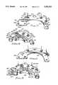
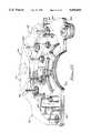
- FIG. 1is an exploded three-dimensional view depicting each of the components constituting the rectifier assembly of the first embodiment.
- FIGS. 1a1 to 1a6are views of the integral preformed leads integument assembly of FIG. 1.
- FIGS. 1b1 to 1b3are views of the extruded isolated cooling member of FIG. 1.
- FIG. 1cis a plan view of the heat conductive electrical insulating gasket of FIG. 1.
- FIGS. 1d and 1d1 to 1d3are views of the direct contacting cooling member of FIG. 1.
- FIG. 1eis a plan view of the four-leaf clover shaped diode header assembly of FIG. 1.
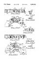
- FIGS. 2a to 2care three-dimensional views depicting the assembly of the four-leaf clover shaped diode header assembly.
- FIG. 3is a three-dimensional view of the direct contacting cooling member assembly of FIG. 1.
- FIG. 4is a three-dimensional view of the insulated cooling member sub-assembly of FIG. 1.
- FIG. 5is a three-dimensional view showing the placement of the gasket unto the direct cooling member sub-assembly in the first embodiment.
- FIG. 6is a three-dimensional view showing placement of the insulated cooling member sub-assembly onto the gasket-direct cooling member sub-assembly in the first embodiment.
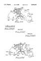
- FIG. 7is a three-dimensional view of the preformed leads before placement into the integument.
- FIG. 8is a three-dimensional view of the integrated preformed lead integument rotated 180 degrees from the viewing plane of FIG. 1.
- FIG. 9is a three-dimensional partial x-ray assembled view of the components of FIG. 1.
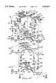
- FIG. 10is an exploded three-dimensional view depicting each of the components constituting the rectifier assembly in the second embodiment.
- FIGS. 10a1 to 10a6are views of the integral preformed leads integument assembly of FIG. 10.
- FIGS. 10b1 to 10b3are views of the isolated cooling member of FIG. 10.
- FIG. 10cis a plan view of the heat conductive electrical insulating gasket of FIG. 10.
- FIGS. 10d and 10d1 to 10d3are views of the direct contacting cooling member of FIG. 10.
- FIG. 11is a three-dimensional view of the direct contacting cooling member assembly of FIG. 10.
- FIG. 12is a three-dimensional view of the insulated cooling member sub-assembly of FIG. 10.
- FIG. 13is a three-dimensional view showing placement of the insulated cooling member sub-assembly of the second embodiment on the direct cooling member sub-assembly with the gasket sandwiched between the two.
- FIG. 14is a three-dimensional view of the integrated preformed lead integument rotated 180 degrees from the viewing plane of FIG. 10.
- FIG. 15is a three-dimensional partial x-ray assembled view of the components of FIG. 10.
- FIG. 1depicts each of the components that constitute the rectifier assembly as the first embodiment of this invention. Each of the components are rotated 45 degrees toward the viewer from a plane projected at the eye level of the viewer.
- FIG. 1depicts the following major sub-assemblies: preformed lead integument 100; insulated cooling member 200; capacitor 300; heat conducting insulator 400; and direct contact cooling member 500.
- Cooling member 500refers to a direct contact cooling member which is also shown in plan view in FIG. 1d.
- Cooling member 500is of either plated aluminum for solderabilty or copper construction, and is dimensioned for mounting in direct contact with a generator.
- Indentations 513, 514, 509, and the unmarked indentation under diode assembly 504are impressed deep enough to provide horizontal placement of their respective components.
- Holes 511 and 515are countersunk underneath so that rivets 507 and 508, once inserted in the holes, do not interfere with the flat surface under the cooling member 500.
- Holes 510 and 512are clearance holes for the rectifier assembly to generator end frame attaching screws (not shown).
- Hole 516is a clearance hole to permit non-conducting passage of an electrode bolt (not shown) which makes contact with insulated cooling member 200 and hole 218.
- FIG. 2depicts the assembly steps for one of the diode-clover shaped header assemblies 504, and FIG. 1e is the plan view of the clover shaped header 204A with the diode chip 204B shown in outline as a dotted line.
- Diode chip 204Bcharacterized by specified impurity doping, is cut to precise dimensions, is metalized, pretinned, and passivated.
- the lower diode header 204A(FIG. 2) of nickel plated copper construction is dropped into a corresponding fixture 204F that has four tines 204T that mate with the four inner surfaces 204I of 204D.
- the tines 204Tare tapered to redirect the header 204A to rest in a repeatable position in the fixture 204F.
- a solder preformis followed by diode chip 204B, is followed by a second solder preform and is followed by a cloverleaf top header 204A into the fixture.
- Slight pressureis exerted on the assembly 504, and the assembly is held together by the adhesive property of the solder preform and is ejected from the tinned fixture and passed into a reflow oven.
- the diode assembly 504consisting of two identical headers 204A, and a diode chip 204B both of FIG. 2 is assembled in a fast and repeatable fashion. It will be appreciated that the outer surfaces 204S of the headers 204A are dimensioned to snugly fit within the holes 512 and 514.
- Extruded insulated cooling member 200 of FIG. 1is shown in plan view in FIG. 1b is fabricated with similar indentations 210, 212, 214, and 215 to provide repeatable horizontal placement of respective diode assemblies 204, 205, and 206 and capacitor terminal 302. Cooling member 200 is extruded aluminum cut to a predetermined thickness, notch by hole 218 is machined to a predetermined thickness and completed insulated cooling member 200 is electroplated with a solderable metal.
- Integral preformed lead integument 100 of FIG. 1is shown in plan view in FIG. 1a and is moreover shown in an inverted position in the three-dimensional view in FIG. 8, with preformed leads shown in proper orientation independent of the integument in FIG. 7.
- Compound holes 106 and 110 of FIG. 1, which are detailed in Detail "B" of FIG. 1a,are made to attach to rivets 507 and 508.
- Preformed leads 101, 102, and 103are of half-hard copper construction and molded into the integument 100 in the fabrication process.
- crimp ends 103, 102, and 101provide a means to connect to the generator stator leads (not shown).
- the height of the crimp ends 103, 102 and 101is made taller so that the stator leads can be cut off an original defective rectifier, leaving ample contact area for a replacement rectifier assembly.
- sections 101D, 101E, 102D 102E, 103D, and 101Eare anchored firmly into the integument.
- terminal ends 101B, 101C, 102B, 102C, 103B, and 103Care free to flex to provide thermal and mechanical stress relief.
- the terminal endsare also formed in a domed shaped configuration with a punched hole in the center of each dome to guide the passage of diode terminals 501, 502, 503, 201, 202, and 203 of FIG. 1.
- Crimp end 103Gprovides passage of stator crimp 103A to external circuitry (not shown).
- Protrusions 108B and 105B of integument 100 of FIG. 8provide an insulated attaching member that fits through holes 213 and 209 of the insulated cooling member 200 of FIG. 1.
- the protrusion 108Bis detailed in Detail "A" of FIG. 1a.
- FIG. 3depicts the completed direct contacting cooling member sub-assembly 500.
- Solder preforms(not shown) of predetermined size are placed into indentations 509, 517, 513, and 514, and then the diode assemblies 504, 505, 506, and capacitor terminal 509 are placed respectively unto the solder preforms.
- the diode assemblies 504-506are tested for polarity and then inverted if necessary before located above respective solder preforms.
- the diode assemblies and the capacitor terminal 301are placed over the solder preforms with a predetermined amount of pressure to compress the solder preform in such a manner to be adhered to the cooling member.
- each diode assembly 504-506has a second solder preform of predetermined size centered, whereby the diode terminals 501, 502, and 503 are pressed on in a similar fashion and held reasonably secure by the compressed solder preform.
- the completed sub-assembly 500is then passed through a time and temperature controlled oven to reflow the preforms in such a manner as to provide an electrically and mechanically sound assembly.
- each diode assembly-lower diode terminal unit 500is sealed with a silicon based substance for addition protection.
- Each diode terminal 501-503has the magnified configuration clearly shown on the right-hand side of FIG. 3, whereby the diode assembly connecting point is of a "S" shaped configuration for additional mechanical and thermal stress relief.
- FIG. 4details the sub-assembly 200 of the insulated cooling member, with procedure of manufacturing being identical as that of the direct contacting cooling member explained with reference to FIG. 3 above.
- FIG. 5depicts the direct cooling member assembly 500 of FIG. 3 with heat conducting insulator 400 in proper position.
- the insulator 400 of FIG. 5is shown retrospective in FIG. 1 and in plan view in FIG. 1c.
- Holes 402 and 404permit passage of rivets 507 and 508.
- Holes 401 and 403permit passage of the protrusions 105B and 108B of the integument, as previously explained.
- Hole 405is made smaller than aligned hole 516 of the direct contacting cooling member, to prevent contact of an insulated cooling member electrode screw (not shown) positioned into hole 218 of the cooling member, hence into hole 405 of the insulator, and thereafter, through hole 516 where the hole 516 does not contact the electrode screw.
- the insulator 400is coated on each side with a thermal conductive compound to further aid in heat transfer before it is positioned on direct cooling member 500 as shown in FIG. 5.
- FIG. 6shows the placement of the insulated cooling member of FIG. 4 onto the direct cooling member-insulator of FIG. 5.
- Pushnuts 207 and 208are pressed onto respective rivets 507 and 508 to unitize the sub-assembly.
- Capacitor 300is then wired onto capacitor terminals 301 and 302 of FIG. 1 and soldered by conventional means.
- FIG. 9depicts in an "x-ray" format the completed rectifier assembly, where all of the components of FIG. 1 are shown in proper position.
- diode terminals 201, 202, 203, 501, 502, and 503 of FIG. 1are soldered to the domes of preformed leads 101B, 101C, 102B, 102C, 103B, and 103C by conventional means.
- each rectifier assembly as shown in FIG. 9undergoes a series of quality and electrical checks, and then individually packaged for shipment.
- FIGS. 10 through 15depict the second embodiment of this invention as previously explained above, and uses like reference numerals followed by a "prime" symbol to indicate a corresponding assembly component or feature.
- numeral 500refers to the cooling member
- numeral 500'refers to the cooling member.
- FIGS. 10-15thus complement FIGS. 1-9.
- cooling member 500' of FIG. 10As to direct contact cooling member 500' of FIG. 10, it will be noted that indentations for diode assemblies and a capacitor terminal in addition to the two countersunk rivet holes share the same geometric positions in each of the cooling members 500 and 500'. However, cooling member 500' of FIG. 10 is expanded in its lateral dimension relative to cooling member 500 by the addition of an extended area 500A' to maximize the contact area with the generator end frame. Area 500A includes arc segment apertures 518', 519', and 520' which correspond to and are dimensioned to overlie similar segments located in the generator end frame when the assembly 500 is installed.
- FIG. 10dis a plan view of the cooling member 500' of FIG. 10.
- the area of the cooling member 500' with the addition of area 500A'is approximately 25% greater than the similar cooling member 500 of FIG. 1. In this manner, each square unit of the cooling member 500 is expected to transfer 20% less of the heat of an equivalent cooling member.
- FIG. 11depicts the completed direct cooling member sub-assembly 500' whereby the assembly is essentially identical after completion as explained under FIG. 3.
- Insulator 400' of FIG. 10complements the insulator 400 of FIG. 1 with added diode assembly and capacitor terminal clearance holes 404', 405', 406', and 402' in addition to arc segment apertures 410', 411', and 412' in extended area 400A'.
- Insulator 400' of FIG. 10is shown in plan view in FIG. 10c and sandwiched between the insulated and direct cooling members in FIG. 13.
- Insulated cooling member 200' of FIG. 10is similar in function to the insulated cooling member 200 of FIG. 1, except that it is not dependent on convection cooling.
- FIG. 10bis a plan view of the insulated cooling member 200', which can either be fabricated of copper or plated aluminum and includes extended area 200A'.
- Direct cooling member diode assemblies and capacitor clearance holesare added to the insulated member 200' at locations 219', 220', 221', and 225'.
- Arc segment ventilation apertures in line with the insulator, direct cooling member, and the generator end frameare located at 222', 223', and 224'.
- Washer 218'is added in line with electrode hole 217' to maintain the same thickness as the similar hole of complementary cooling member 200 of FIG. 1.
- FIG. 11depicts the insulated cooling member sub-assembly which share an identical assembly process as explained under FIG. 4 above.
- FIG. 13depicts the joining of the insulated and direct cooling members of FIGS. 11 and 12, which is assembled identically as discussed above with reference to FIG. 6.
- FIG. 14shares the same preformed leads of FIG. 7, and is identical in attachment and function to complement the integral preformed lead integument shown in FIG. 8.
- FIG. 10ais a plan view of the integument depicting the variations to maintain the same overall outline as the integument in FIG. 1a.
- FIG. 15shows a partial "x-ray view" of the completed rectifier assembly of the second embodiment.
- FIGS. 9 and 15depict a rectifier assembly that is interchangeable; however, the rectifier assembly of FIG. 15 has a greater ability to transfer a far greater portion of the diode-generated heat to the direct cooling member and sequentially to the end frame.
- the arc segment aperturesare far less susceptible to blockage or environmental paraphernalia that occurs naturally due to the far greater area of the segments. Furthermore, the increased area of the arc segment apertures permits a far greater flow of the cooling medium.
- the voltage regulatorshares a common end frame with the rectifier assembly. Since the voltage regulator consists of a common diode thermal shut-down circuit, then the rectifier assembly of this invention will transfer a far greater percentage of heat to the generator end frame. The voltage regulator will also shut down the generator by interrupting the flow of field current, and the voltage regulator will then activate a warning lamp to indicate to the vehicle operator that a malfunction has occurred. This permits the rectifier assembly to cool before permanent destruction occurs. If the operator is instructed to check for a generator ventilation blockage, the blockage results in a minor inconvenience as opposed to prior art rectifier assemblies, where a blockage often causes permanent damage to the rectifier assembly.
- the limit of current outputis dependent on not exceeding a predetermined diode junction temperature, and is as such that if means were taken to remove the diode self-generated heat in a more efficient manner, that the diode assembly would be capable of outputting a greater current in a similar size package, such is the case of the second embodiment of FIGS. 10-15.
Landscapes
- Engineering & Computer Science (AREA)
- Power Engineering (AREA)
- Microelectronics & Electronic Packaging (AREA)
- Physics & Mathematics (AREA)
- Condensed Matter Physics & Semiconductors (AREA)
- General Physics & Mathematics (AREA)
- Computer Hardware Design (AREA)
- Rectifiers (AREA)
- Synchronous Machinery (AREA)
Abstract
Description
Claims (21)
Priority Applications (1)
| Application Number | Priority Date | Filing Date | Title |
|---|---|---|---|
| US08/016,504US5451823A (en) | 1993-02-11 | 1993-02-11 | Vehicular thermoconductive lead frame rectifier assembly |
Applications Claiming Priority (1)
| Application Number | Priority Date | Filing Date | Title |
|---|---|---|---|
| US08/016,504US5451823A (en) | 1993-02-11 | 1993-02-11 | Vehicular thermoconductive lead frame rectifier assembly |
Publications (1)
| Publication Number | Publication Date |
|---|---|
| US5451823Atrue US5451823A (en) | 1995-09-19 |
Family
ID=21777464
Family Applications (1)
| Application Number | Title | Priority Date | Filing Date |
|---|---|---|---|
| US08/016,504Expired - LifetimeUS5451823A (en) | 1993-02-11 | 1993-02-11 | Vehicular thermoconductive lead frame rectifier assembly |
Country Status (1)
| Country | Link |
|---|---|
| US (1) | US5451823A (en) |
Cited By (48)
| Publication number | Priority date | Publication date | Assignee | Title |
|---|---|---|---|---|
| WO1996019032A1 (en)* | 1994-12-16 | 1996-06-20 | Depetris Peter S | Rectifier assembly for automotive alternator |
| US5640062A (en)* | 1994-03-10 | 1997-06-17 | Ford Motor Company | Alternator with internal rectifier bridge assembly |
| US5646838A (en)* | 1995-12-13 | 1997-07-08 | Integral Automotive S.A. | Bridge rectifier for diode-rectified alternating current generator |
| US5682070A (en)* | 1995-06-28 | 1997-10-28 | Mitsubishi Denki Kabushiki Kaisha | Vehicle-mounted alternator |
| US5705867A (en)* | 1995-06-13 | 1998-01-06 | Mando Machinery Corporation | Insulating plate with support for terminal plate of an alternator |
| US5723936A (en)* | 1995-06-19 | 1998-03-03 | Wagner Product Co. | Battery isolator bracket heat sink |
| US5777407A (en)* | 1994-03-11 | 1998-07-07 | Nippondenso Co., Ltd. | Alternator for vehicle |
| DE19705228A1 (en)* | 1997-02-12 | 1998-08-13 | Bosch Gmbh Robert | Electrical machine, preferably a three-phase generator with a rectifier unit |
| US5812388A (en)* | 1995-12-13 | 1998-09-22 | Integral Automotive S.A. | Bridge rectifier for diode-rectified alternating current generator |
| US5866963A (en)* | 1997-01-30 | 1999-02-02 | Renard Manufacturing Co., Inc. | Bridge rectifier with insulating support having expandable legs |
| US5883450A (en)* | 1995-05-17 | 1999-03-16 | Valeo Equipements Electriques Moteur | Alternator, in particular for a motor vehicle including an improved arrangement of rectifier diodes |
| US5892308A (en)* | 1996-07-30 | 1999-04-06 | Valeo Equipements Electriques Moteur | Rectifier assembly of a motor vehicle alternator with a thermal dissipator |
| US5991184A (en)* | 1999-03-02 | 1999-11-23 | Transpo Electronics, Inc. | Vehicular extended thermal cycle minimal part robust rectifier assembly |
| US6081054A (en)* | 1998-09-04 | 2000-06-27 | Mitsubishi Denki Kabushiki Kaisha | Automotive alternator |
| US6204581B1 (en)* | 1999-05-24 | 2001-03-20 | Shih-Kaung Lo | Commutator heat dissipating device for alternators |
| US6278206B1 (en) | 2000-06-28 | 2001-08-21 | Visteon Global Technologies, Inc. | Electrical connection apparatus and method for connecting an alternator stator |
| US6291913B1 (en)* | 1999-06-29 | 2001-09-18 | Mitsubishi Denki Kabushiki Kaisha | Automotive alternator |
| US6307289B1 (en) | 1998-06-26 | 2001-10-23 | Robert Bosch Gmbh | Electrical machine with rectifier unit and plus and minus heat sinks with improved lost heat dissipation |
| EP1184960A1 (en)* | 2000-09-01 | 2002-03-06 | Mitsubishi Denki Kabushiki Kaisha | Vehicle-onboard AC generator |
| US6429556B1 (en)* | 1999-06-01 | 2002-08-06 | Denso Corporation | AC generator for vehicle |
| US6528911B1 (en) | 1998-10-07 | 2003-03-04 | Electro-Dyn Electronics Corporation | Rectifier assembly for automotive alternators |
| US6552908B2 (en) | 2001-02-21 | 2003-04-22 | Transpo Electronics, Inc. | Vehicular modular design multiple application rectifier assembly having outer lead integument |
| US6621703B2 (en) | 1998-10-07 | 2003-09-16 | Electro-Dyn Electronics Corporation | Automotive bridge rectifier assembly with thermal protection |
| US20030197437A1 (en)* | 2002-04-19 | 2003-10-23 | Hitachi, Ltd. | Alternator for vehicle |
| US6642078B2 (en) | 2000-08-28 | 2003-11-04 | Transpo Electronics, Inc. | Method for manufacturing diode subassemblies used in rectifier assemblies of engine driven generators |
| US6661662B2 (en) | 2001-02-21 | 2003-12-09 | Transpo Electronics, Inc. | Vehicular modular design multiple application rectifier assembly |
| US20040256925A1 (en)* | 2003-06-18 | 2004-12-23 | Transpo Electronics, Inc. | Rectifier for a vehicle alternator |
| US20050001492A1 (en)* | 2003-07-03 | 2005-01-06 | Bradfield Michael D. | Electronic package for electrical machine |
| US6882069B1 (en)* | 2000-06-08 | 2005-04-19 | Mitsubishi Denki Kabushiki Kaisha | Vehicle AC generator with rectifier diode package disposed between cooling plates |
| US20050127763A1 (en)* | 2003-12-16 | 2005-06-16 | Wetherill Associates, Inc. | Bridge rectifier for charging system alternator |
| US6949849B1 (en)* | 1998-06-30 | 2005-09-27 | General Electric Company | Motor endshield assembly for an electronically commutated motor |
| US20060017337A1 (en)* | 2004-07-20 | 2006-01-26 | Wetherill Associates, Inc. | Rectifier with extended stator lead connector used for charging system alternator |
| US20060043805A1 (en)* | 2004-09-01 | 2006-03-02 | Bradfield Michael D | Electronic package for electrical machine |
| US20060131970A1 (en)* | 2003-12-01 | 2006-06-22 | Karam Roy N | Slip ring end frame |
| US20060131969A1 (en)* | 2004-12-21 | 2006-06-22 | Electro-Dyn Choke Corporation | Rectifier assembly with enhanced air cooling |
| FR2886476A1 (en)* | 2005-05-31 | 2006-12-01 | Valeo Equip Electr Moteur | POWER INTERCONNECTION PIECE FOR ROTATING ELECTRIC MACHINE |
| US20070103012A1 (en)* | 2005-11-10 | 2007-05-10 | Korea Delphi Automotive Systems Corporation | Method of manufacturing terminal assembly of alternator for vehicles and terminal assembly manufactured by the method |
| US20070182023A1 (en)* | 2006-02-08 | 2007-08-09 | Hitachi, Ltd. | Semiconductor device |
| US20080018186A1 (en)* | 2006-07-14 | 2008-01-24 | Justin Lybbert | Rectifier bridge assembly for an automotive application |
| US20080191588A1 (en)* | 2005-05-31 | 2008-08-14 | Valeo Equipements Electriques Moteur | Signal Interconnecting Part for Electrical Rotating Machine |
| US20080197727A1 (en)* | 2005-05-31 | 2008-08-21 | Valeo Equipements Electriques Moteur | Heat Sink For Electronic Components of a Rotating Electric Machine |
| US20080197726A1 (en)* | 2005-05-31 | 2008-08-21 | Valeo Equipements Electriques Moteur | Assembly of Electronic Components for Electrical Rotating Machine |
| US20080211331A1 (en)* | 2005-05-31 | 2008-09-04 | Valeo Equipements Electriques Moteur | Electronic Module for Rotating Electrical Machine |
| CN100477452C (en)* | 2003-07-03 | 2009-04-08 | 雷米国际公司 | Electronic packaging device for motor |
| US20130155635A1 (en)* | 2010-10-19 | 2013-06-20 | Mitsubishi Electric Corporation | Automotive alternator rectifying apparatus |
| US8745847B2 (en) | 2011-11-17 | 2014-06-10 | Remy Technologies, L.L.C. | Method of P-forming a continuous conductor having a rectangular cross section and a stator including a stator winding formed from a P-formed conductor having a rectangular cross-section |
| US8789259B2 (en) | 2011-11-17 | 2014-07-29 | Remy Technologies, L.L.C. | Method of winding a stator core with a continuous conductor having a rectangular cross-section and a stator core |
| US9467010B2 (en) | 2011-11-17 | 2016-10-11 | Remy Technologies, L.L.C. | Method of winding a stator core with a continuous conductor having a rectangular cross-section and a stator core |
Citations (11)
| Publication number | Priority date | Publication date | Assignee | Title |
|---|---|---|---|---|
| US3629631A (en)* | 1969-06-09 | 1971-12-21 | Herbert John Thomas Cotton | Full wave rectifier assemblies |
| US3641374A (en)* | 1970-03-11 | 1972-02-08 | Nippon Denso Co | Rectifying means for three-phase alternating generators for use in vehicles and other transport facilities |
| US3812390A (en)* | 1973-07-13 | 1974-05-21 | Wagner Electric Corp | Alternator rectifier |
| US3927338A (en)* | 1975-01-02 | 1975-12-16 | Motorola Inc | Automotive bridge assembly |
| US3959676A (en)* | 1974-12-23 | 1976-05-25 | Ford Motor Company | Alternator rectifier bridge and method of assembly |
| US4189653A (en)* | 1977-03-19 | 1980-02-19 | Hitachi, Ltd. | Rectifier assembly for rectifying output of alternator for internal combustion engine |
| US4419597A (en)* | 1980-05-09 | 1983-12-06 | Nippondenso Co., Ltd. | Alternator assembly having a rectifier device in thermal contact with case and cover |
| US4604538A (en)* | 1985-02-19 | 1986-08-05 | General Motors Corporation | Air cooling for diode-rectified alternating current generators |
| US4606000A (en)* | 1985-03-27 | 1986-08-12 | General Motors Corporation | Bridge rectifier |
| US5043614A (en)* | 1990-02-02 | 1991-08-27 | Ford Motor Company | Alternator rectifier bridge assembly |
| US5233246A (en)* | 1992-08-13 | 1993-08-03 | Ford Motor Company | Insert molded terminal for alternator |
- 1993
- 1993-02-11USUS08/016,504patent/US5451823A/ennot_activeExpired - Lifetime
Patent Citations (11)
| Publication number | Priority date | Publication date | Assignee | Title |
|---|---|---|---|---|
| US3629631A (en)* | 1969-06-09 | 1971-12-21 | Herbert John Thomas Cotton | Full wave rectifier assemblies |
| US3641374A (en)* | 1970-03-11 | 1972-02-08 | Nippon Denso Co | Rectifying means for three-phase alternating generators for use in vehicles and other transport facilities |
| US3812390A (en)* | 1973-07-13 | 1974-05-21 | Wagner Electric Corp | Alternator rectifier |
| US3959676A (en)* | 1974-12-23 | 1976-05-25 | Ford Motor Company | Alternator rectifier bridge and method of assembly |
| US3927338A (en)* | 1975-01-02 | 1975-12-16 | Motorola Inc | Automotive bridge assembly |
| US4189653A (en)* | 1977-03-19 | 1980-02-19 | Hitachi, Ltd. | Rectifier assembly for rectifying output of alternator for internal combustion engine |
| US4419597A (en)* | 1980-05-09 | 1983-12-06 | Nippondenso Co., Ltd. | Alternator assembly having a rectifier device in thermal contact with case and cover |
| US4604538A (en)* | 1985-02-19 | 1986-08-05 | General Motors Corporation | Air cooling for diode-rectified alternating current generators |
| US4606000A (en)* | 1985-03-27 | 1986-08-12 | General Motors Corporation | Bridge rectifier |
| US5043614A (en)* | 1990-02-02 | 1991-08-27 | Ford Motor Company | Alternator rectifier bridge assembly |
| US5233246A (en)* | 1992-08-13 | 1993-08-03 | Ford Motor Company | Insert molded terminal for alternator |
Cited By (79)
| Publication number | Priority date | Publication date | Assignee | Title |
|---|---|---|---|---|
| US5640062A (en)* | 1994-03-10 | 1997-06-17 | Ford Motor Company | Alternator with internal rectifier bridge assembly |
| US5777407A (en)* | 1994-03-11 | 1998-07-07 | Nippondenso Co., Ltd. | Alternator for vehicle |
| WO1996019032A1 (en)* | 1994-12-16 | 1996-06-20 | Depetris Peter S | Rectifier assembly for automotive alternator |
| US5659212A (en)* | 1994-12-16 | 1997-08-19 | Electro-Dyn Choke Corporation | Rectifier assembly for automotive alternator |
| US5883450A (en)* | 1995-05-17 | 1999-03-16 | Valeo Equipements Electriques Moteur | Alternator, in particular for a motor vehicle including an improved arrangement of rectifier diodes |
| US5705867A (en)* | 1995-06-13 | 1998-01-06 | Mando Machinery Corporation | Insulating plate with support for terminal plate of an alternator |
| US5723936A (en)* | 1995-06-19 | 1998-03-03 | Wagner Product Co. | Battery isolator bracket heat sink |
| US5682070A (en)* | 1995-06-28 | 1997-10-28 | Mitsubishi Denki Kabushiki Kaisha | Vehicle-mounted alternator |
| US5812388A (en)* | 1995-12-13 | 1998-09-22 | Integral Automotive S.A. | Bridge rectifier for diode-rectified alternating current generator |
| US5646838A (en)* | 1995-12-13 | 1997-07-08 | Integral Automotive S.A. | Bridge rectifier for diode-rectified alternating current generator |
| US5892308A (en)* | 1996-07-30 | 1999-04-06 | Valeo Equipements Electriques Moteur | Rectifier assembly of a motor vehicle alternator with a thermal dissipator |
| US5866963A (en)* | 1997-01-30 | 1999-02-02 | Renard Manufacturing Co., Inc. | Bridge rectifier with insulating support having expandable legs |
| AU723927B2 (en)* | 1997-02-12 | 2000-09-07 | Robert Bosch Gmbh | Electric machine, preferably an alternator with a rectifier component |
| DE19705228A1 (en)* | 1997-02-12 | 1998-08-13 | Bosch Gmbh Robert | Electrical machine, preferably a three-phase generator with a rectifier unit |
| WO1998036486A1 (en)* | 1997-02-12 | 1998-08-20 | Robert Bosch Gmbh | Electric machine, preferably a three-phase generator with rectifier unit |
| US6307289B1 (en) | 1998-06-26 | 2001-10-23 | Robert Bosch Gmbh | Electrical machine with rectifier unit and plus and minus heat sinks with improved lost heat dissipation |
| US6949849B1 (en)* | 1998-06-30 | 2005-09-27 | General Electric Company | Motor endshield assembly for an electronically commutated motor |
| US6081054A (en)* | 1998-09-04 | 2000-06-27 | Mitsubishi Denki Kabushiki Kaisha | Automotive alternator |
| US6621703B2 (en) | 1998-10-07 | 2003-09-16 | Electro-Dyn Electronics Corporation | Automotive bridge rectifier assembly with thermal protection |
| US6528911B1 (en) | 1998-10-07 | 2003-03-04 | Electro-Dyn Electronics Corporation | Rectifier assembly for automotive alternators |
| US20040092147A1 (en)* | 1998-10-07 | 2004-05-13 | De Petris Peter S. | Connector for automotive bridge rectifier assembly |
| US5991184A (en)* | 1999-03-02 | 1999-11-23 | Transpo Electronics, Inc. | Vehicular extended thermal cycle minimal part robust rectifier assembly |
| US6204581B1 (en)* | 1999-05-24 | 2001-03-20 | Shih-Kaung Lo | Commutator heat dissipating device for alternators |
| US6429556B1 (en)* | 1999-06-01 | 2002-08-06 | Denso Corporation | AC generator for vehicle |
| US6291913B1 (en)* | 1999-06-29 | 2001-09-18 | Mitsubishi Denki Kabushiki Kaisha | Automotive alternator |
| US6882069B1 (en)* | 2000-06-08 | 2005-04-19 | Mitsubishi Denki Kabushiki Kaisha | Vehicle AC generator with rectifier diode package disposed between cooling plates |
| US6278206B1 (en) | 2000-06-28 | 2001-08-21 | Visteon Global Technologies, Inc. | Electrical connection apparatus and method for connecting an alternator stator |
| US6642078B2 (en) | 2000-08-28 | 2003-11-04 | Transpo Electronics, Inc. | Method for manufacturing diode subassemblies used in rectifier assemblies of engine driven generators |
| US20040014256A1 (en)* | 2000-08-28 | 2004-01-22 | Transpo Electronics, Inc. | Method for manufacturing diode subassemblies used in rectifier assemblies of engine driven generators |
| US7060533B2 (en) | 2000-08-28 | 2006-06-13 | Wetherill Associates, Inc. | Method for manufacturing diode subassemblies used in rectifier assemblies of engine driven generators |
| US6664677B2 (en)* | 2000-09-01 | 2003-12-16 | Mitsubishi Denki Kabushiki Kaisha | Vehicle-onboard AC generator |
| US20020033646A1 (en)* | 2000-09-01 | 2002-03-21 | Kazunori Tanaka | Vehicle-onboard AC generator |
| EP1184960A1 (en)* | 2000-09-01 | 2002-03-06 | Mitsubishi Denki Kabushiki Kaisha | Vehicle-onboard AC generator |
| US6661662B2 (en) | 2001-02-21 | 2003-12-09 | Transpo Electronics, Inc. | Vehicular modular design multiple application rectifier assembly |
| US6552908B2 (en) | 2001-02-21 | 2003-04-22 | Transpo Electronics, Inc. | Vehicular modular design multiple application rectifier assembly having outer lead integument |
| US20030197437A1 (en)* | 2002-04-19 | 2003-10-23 | Hitachi, Ltd. | Alternator for vehicle |
| US7336008B2 (en)* | 2002-04-19 | 2008-02-26 | Hitachi, Ltd. | Weld joining portion of a vehicle alternator |
| US20040256925A1 (en)* | 2003-06-18 | 2004-12-23 | Transpo Electronics, Inc. | Rectifier for a vehicle alternator |
| WO2005001936A1 (en)* | 2003-06-18 | 2005-01-06 | Wetherill Associates, Inc. | Rectifier for a vehicle alternator |
| US6911750B2 (en)* | 2003-07-03 | 2005-06-28 | Delco Remy International, Inc. | Electronic package for electrical machine |
| CN100477452C (en)* | 2003-07-03 | 2009-04-08 | 雷米国际公司 | Electronic packaging device for motor |
| US6995486B2 (en) | 2003-07-03 | 2006-02-07 | Remy International, Inc. | Electronic package for electrical machine |
| US20050001492A1 (en)* | 2003-07-03 | 2005-01-06 | Bradfield Michael D. | Electronic package for electrical machine |
| WO2005011090A1 (en)* | 2003-07-03 | 2005-02-03 | Remy International, Inc. | Electronic package for electrical machine |
| US20050194850A1 (en)* | 2003-07-03 | 2005-09-08 | Bradfield Michael D. | Electronic package for electrical machine |
| US20060131970A1 (en)* | 2003-12-01 | 2006-06-22 | Karam Roy N | Slip ring end frame |
| US7368839B2 (en)* | 2003-12-01 | 2008-05-06 | Karam Roy N | Slip ring end frame |
| US20050127763A1 (en)* | 2003-12-16 | 2005-06-16 | Wetherill Associates, Inc. | Bridge rectifier for charging system alternator |
| US7116021B2 (en) | 2003-12-16 | 2006-10-03 | Wetherill Associates, Inc. | Bridge rectifier for charging system alternator |
| US20060017337A1 (en)* | 2004-07-20 | 2006-01-26 | Wetherill Associates, Inc. | Rectifier with extended stator lead connector used for charging system alternator |
| US20060043805A1 (en)* | 2004-09-01 | 2006-03-02 | Bradfield Michael D | Electronic package for electrical machine |
| US7417344B2 (en) | 2004-09-01 | 2008-08-26 | Remy International, Inc. | Electronic package for electrical machine |
| US20070210662A1 (en)* | 2004-09-01 | 2007-09-13 | Remy International, Inc. | Electronic package for electrical machine |
| WO2006028981A3 (en)* | 2004-09-01 | 2008-01-24 | Remy Int Inc | Electronic package for electrical machine |
| US7352091B2 (en)* | 2004-09-01 | 2008-04-01 | Remy International, Inc. | Electronic package for electrical machine |
| US7612474B2 (en)* | 2004-12-21 | 2009-11-03 | Electric-Dyn Choke Corporation | Rectifier assembly with enhanced air cooling |
| US20060131969A1 (en)* | 2004-12-21 | 2006-06-22 | Electro-Dyn Choke Corporation | Rectifier assembly with enhanced air cooling |
| FR2886476A1 (en)* | 2005-05-31 | 2006-12-01 | Valeo Equip Electr Moteur | POWER INTERCONNECTION PIECE FOR ROTATING ELECTRIC MACHINE |
| US7763997B2 (en) | 2005-05-31 | 2010-07-27 | Valeo Equipements Electriques Moteur | Heat sink for electronic components of a rotating electric machine |
| US20080191588A1 (en)* | 2005-05-31 | 2008-08-14 | Valeo Equipements Electriques Moteur | Signal Interconnecting Part for Electrical Rotating Machine |
| US20080197727A1 (en)* | 2005-05-31 | 2008-08-21 | Valeo Equipements Electriques Moteur | Heat Sink For Electronic Components of a Rotating Electric Machine |
| US20080197726A1 (en)* | 2005-05-31 | 2008-08-21 | Valeo Equipements Electriques Moteur | Assembly of Electronic Components for Electrical Rotating Machine |
| US7932649B2 (en) | 2005-05-31 | 2011-04-26 | Valeo Equipements Electriques Moteur | Signal interconnecting part for electrical rotating machine |
| US20080211331A1 (en)* | 2005-05-31 | 2008-09-04 | Valeo Equipements Electriques Moteur | Electronic Module for Rotating Electrical Machine |
| US20080311763A1 (en)* | 2005-05-31 | 2008-12-18 | Valeo Equipements Electriques Moteur | Power Interconnecting Part for Electrical Rotating Machine |
| US7872383B2 (en) | 2005-05-31 | 2011-01-18 | Valeo Equipements Electriques Moteur | Power interconnecting part for electrical rotating machine |
| WO2006129031A1 (en)* | 2005-05-31 | 2006-12-07 | Valeo Equipements Electriques Moteur | Power interconnecting part for electrical rotating machine |
| US7859147B2 (en) | 2005-05-31 | 2010-12-28 | Valeo Equipements Electriques Moteur | Electronic module for rotating electrical machine |
| US7800264B2 (en) | 2005-05-31 | 2010-09-21 | Valeo Equipements Electriques Moteur | Assembly of electronic components for electrical rotating machine |
| US7728471B2 (en)* | 2005-11-10 | 2010-06-01 | Korea Delphi Automotive Systems Corporation | Method of manufacturing terminal assembly of alternator for vehicles and terminal assembly manufactured by the method |
| US20070103012A1 (en)* | 2005-11-10 | 2007-05-10 | Korea Delphi Automotive Systems Corporation | Method of manufacturing terminal assembly of alternator for vehicles and terminal assembly manufactured by the method |
| US20070182023A1 (en)* | 2006-02-08 | 2007-08-09 | Hitachi, Ltd. | Semiconductor device |
| US20080018186A1 (en)* | 2006-07-14 | 2008-01-24 | Justin Lybbert | Rectifier bridge assembly for an automotive application |
| US7876007B2 (en)* | 2006-07-14 | 2011-01-25 | Lybbert Justin B | Rectifier bridge assembly for an automotive application |
| US20130155635A1 (en)* | 2010-10-19 | 2013-06-20 | Mitsubishi Electric Corporation | Automotive alternator rectifying apparatus |
| US9131612B2 (en)* | 2010-10-19 | 2015-09-08 | Mitsubishi Electric Corporation | Automotive alternator rectifying apparatus |
| US8745847B2 (en) | 2011-11-17 | 2014-06-10 | Remy Technologies, L.L.C. | Method of P-forming a continuous conductor having a rectangular cross section and a stator including a stator winding formed from a P-formed conductor having a rectangular cross-section |
| US8789259B2 (en) | 2011-11-17 | 2014-07-29 | Remy Technologies, L.L.C. | Method of winding a stator core with a continuous conductor having a rectangular cross-section and a stator core |
| US9467010B2 (en) | 2011-11-17 | 2016-10-11 | Remy Technologies, L.L.C. | Method of winding a stator core with a continuous conductor having a rectangular cross-section and a stator core |
Similar Documents
| Publication | Publication Date | Title |
|---|---|---|
| US5451823A (en) | Vehicular thermoconductive lead frame rectifier assembly | |
| US5991184A (en) | Vehicular extended thermal cycle minimal part robust rectifier assembly | |
| US5659212A (en) | Rectifier assembly for automotive alternator | |
| US5640062A (en) | Alternator with internal rectifier bridge assembly | |
| EP0440395B1 (en) | Alternator rectifier bridge assembly | |
| US4689597A (en) | Electrical fuse component and method of using same | |
| EP0936400B1 (en) | Multiple light emitting diode module | |
| US3959676A (en) | Alternator rectifier bridge and method of assembly | |
| EP0097782B1 (en) | Thermal conduction bridge element for semiconductor device packages | |
| US5109320A (en) | System for connecting integrated circuit dies to a printed wiring board | |
| CN100499177C (en) | Solar cell module connector and method of producing solar cell module panel | |
| EP0420413B1 (en) | Means and method of securing an insert in a shell | |
| EP0088246B1 (en) | Telescopic thermal conduction element for semiconductor devices | |
| US6750535B2 (en) | Package for enclosing a laser diode module | |
| US6552908B2 (en) | Vehicular modular design multiple application rectifier assembly having outer lead integument | |
| WO1996024943A1 (en) | Battery pack having a ruggedized thermal fuse | |
| EP0110452B1 (en) | Integrated alternator bridge heat sink | |
| JP2001143805A (en) | Electrical connector having continuous thin leaf terminals | |
| US20030198068A1 (en) | Compact rectifier bridge and method for manufacturing the same | |
| US6661662B2 (en) | Vehicular modular design multiple application rectifier assembly | |
| US20020158320A1 (en) | Light-emitting diode and a method for its manufacture | |
| JPH088396A (en) | Rectifier device | |
| US3059157A (en) | Semiconductor rectifier | |
| EP0499109A1 (en) | Fused chip-type solid electrolytic capacitor and method of manufacturing the same | |
| CA1291236C (en) | Electrical connector fabricated with unitary frame |
Legal Events
| Date | Code | Title | Description |
|---|---|---|---|
| AS | Assignment | Owner name:TRANSPO ELECTRONICS, INC., FLORIDA Free format text:ASSIGNMENT OF ASSIGNORS INTEREST.;ASSIGNORS:DEVERALL, ROBERT M.;DENARDIS, NICHOLAS F.;SIMMONS, MICHAEL C.;REEL/FRAME:006438/0212;SIGNING DATES FROM 19930209 TO 19930211 | |
| STCF | Information on status: patent grant | Free format text:PATENTED CASE | |
| FEPP | Fee payment procedure | Free format text:PAT HLDR NO LONGER CLAIMS SMALL ENT STAT AS SMALL BUSINESS (ORIGINAL EVENT CODE: LSM2); ENTITY STATUS OF PATENT OWNER: LARGE ENTITY | |
| FPAY | Fee payment | Year of fee payment:4 | |
| REMI | Maintenance fee reminder mailed | ||
| FPAY | Fee payment | Year of fee payment:8 | |
| SULP | Surcharge for late payment | Year of fee payment:7 | |
| AS | Assignment | Owner name:PNC BANK NATIONAL ASSOCIATION, NEW JERSEY Free format text:ASSIGNMENT OF ASSIGNORS INTEREST;ASSIGNOR:TRANSPO ELECTRONICS, INC.;REEL/FRAME:014491/0753 Effective date:20021017 | |
| AS | Assignment | Owner name:GENERAL ELECTRIC CAPITAL CORPORATION, AS AGENT, CO Free format text:SECURITY AGREEMENT;ASSIGNOR:WETHERILL ASSOCIATES, INC., A DELAWARE CORPORATION;REEL/FRAME:014446/0228 Effective date:20040308 | |
| AS | Assignment | Owner name:WETHERILL ASSOCIATES, INC., PENNSYLVANIA Free format text:ASSIGNMENT OF ASSIGNORS INTEREST;ASSIGNOR:TRANSPO ELECTRONICS, INC.;REEL/FRAME:014462/0694 Effective date:20040308 | |
| REMI | Maintenance fee reminder mailed | ||
| FPAY | Fee payment | Year of fee payment:12 | |
| SULP | Surcharge for late payment | Year of fee payment:11 | |
| AS | Assignment | Owner name:WETHERILL ASSOCIATES, INC., PENNSYLVANIA Free format text:TERMINATION AND RELEASE OF PATENT SECURITY AGREEMENT;ASSIGNOR:GENERAL ELECTRIC CAPITAL CORPORATION, AS AGENT;REEL/FRAME:025528/0325 Effective date:20101217 Owner name:WETHERILL REBUILDERS SUPPLY, INC, PENNSYLVANIA Free format text:TERMINATION AND RELEASE OF PATENT SECURITY AGREEMENT;ASSIGNOR:GENERAL ELECTRIC CAPITAL CORPORATION, AS AGENT;REEL/FRAME:025528/0325 Effective date:20101217 Owner name:WETHERILL PROPERTIES, LTD., PENNSYLVANIA Free format text:TERMINATION AND RELEASE OF PATENT SECURITY AGREEMENT;ASSIGNOR:GENERAL ELECTRIC CAPITAL CORPORATION, AS AGENT;REEL/FRAME:025528/0325 Effective date:20101217 Owner name:WETHERILL ENTERPRISES, INC., PENNSYLVANIA Free format text:TERMINATION AND RELEASE OF PATENT SECURITY AGREEMENT;ASSIGNOR:GENERAL ELECTRIC CAPITAL CORPORATION, AS AGENT;REEL/FRAME:025528/0325 Effective date:20101217 Owner name:WETHERILL CYMA, INC., PENNSYLVANIA Free format text:TERMINATION AND RELEASE OF PATENT SECURITY AGREEMENT;ASSIGNOR:GENERAL ELECTRIC CAPITAL CORPORATION, AS AGENT;REEL/FRAME:025528/0325 Effective date:20101217 | |
| AS | Assignment | Owner name:PNC BANK, NATIONAL ASSOCIATION, PENNSYLVANIA Free format text:SECURITY AGREEMENT;ASSIGNOR:WETHERILL ASSOCIATES, INC;REEL/FRAME:025573/0307 Effective date:20101202 | |
| AS | Assignment | Owner name:WETHERILL ASSOCIATES INC, PENNSYLVANIA Free format text:RELEASE BY SECURED PARTY;ASSIGNOR:PNC BANK NATIONAL ASSOCIATION;REEL/FRAME:055633/0691 Effective date:20210317 |