US5450203A - Method and apparatus for determining an objects position, topography and for imaging - Google Patents
Method and apparatus for determining an objects position, topography and for imagingDownload PDFInfo
- Publication number
- US5450203A US5450203AUS08/172,426US17242693AUS5450203AUS 5450203 AUS5450203 AUS 5450203AUS 17242693 AUS17242693 AUS 17242693AUS 5450203 AUS5450203 AUS 5450203A
- Authority
- US
- United States
- Prior art keywords
- radiation
- site
- point
- focusing
- reflected radiation
- Prior art date
- Legal status (The legal status is an assumption and is not a legal conclusion. Google has not performed a legal analysis and makes no representation as to the accuracy of the status listed.)
- Expired - Lifetime
Links
- 238000000034methodMethods0.000titleclaimsabstractdescription47
- 238000012876topographyMethods0.000titleabstractdescription8
- 238000003384imaging methodMethods0.000titledescription6
- 239000000523sampleSubstances0.000claimsabstractdescription126
- 239000013307optical fiberSubstances0.000claimsabstractdescription71
- 230000005855radiationEffects0.000claimsdescription126
- 230000003287optical effectEffects0.000claimsdescription10
- 239000004065semiconductorSubstances0.000claimsdescription10
- 239000000758substrateSubstances0.000claimsdescription7
- 230000004044responseEffects0.000abstractdescription5
- 238000002310reflectometryMethods0.000abstractdescription3
- 239000000835fiberSubstances0.000description88
- 235000012431wafersNutrition0.000description70
- 238000012360testing methodMethods0.000description10
- 238000013480data collectionMethods0.000description6
- 230000003247decreasing effectEffects0.000description6
- 239000012528membraneSubstances0.000description5
- 238000005253claddingMethods0.000description4
- 238000009826distributionMethods0.000description4
- 230000035945sensitivityEffects0.000description4
- 241000270295SerpentesSpecies0.000description3
- 238000003491arrayMethods0.000description3
- 230000000694effectsEffects0.000description3
- 239000000463materialSubstances0.000description3
- 230000008569processEffects0.000description3
- 230000000007visual effectEffects0.000description3
- XUIMIQQOPSSXEZ-UHFFFAOYSA-NSiliconChemical compound[Si]XUIMIQQOPSSXEZ-UHFFFAOYSA-N0.000description2
- XAGFODPZIPBFFR-UHFFFAOYSA-NaluminiumChemical compound[Al]XAGFODPZIPBFFR-UHFFFAOYSA-N0.000description2
- 229910052782aluminiumInorganic materials0.000description2
- 230000005540biological transmissionEffects0.000description2
- 230000007423decreaseEffects0.000description2
- 238000001514detection methodMethods0.000description2
- 238000001914filtrationMethods0.000description2
- 238000005286illuminationMethods0.000description2
- 238000005259measurementMethods0.000description2
- 230000009467reductionEffects0.000description2
- 229910052710siliconInorganic materials0.000description2
- 239000010703siliconSubstances0.000description2
- 239000004642PolyimideSubstances0.000description1
- 238000013459approachMethods0.000description1
- 230000002301combined effectEffects0.000description1
- 238000011109contaminationMethods0.000description1
- 230000008878couplingEffects0.000description1
- 238000010168coupling processMethods0.000description1
- 238000005859coupling reactionMethods0.000description1
- 238000005520cutting processMethods0.000description1
- 230000003993interactionEffects0.000description1
- 238000004519manufacturing processMethods0.000description1
- 238000013507mappingMethods0.000description1
- 238000013178mathematical modelMethods0.000description1
- 238000012986modificationMethods0.000description1
- 230000004048modificationEffects0.000description1
- 238000004806packaging method and processMethods0.000description1
- 238000012856packingMethods0.000description1
- 229920001721polyimidePolymers0.000description1
- 238000005070samplingMethods0.000description1
- 229910000679solderInorganic materials0.000description1
Images


Classifications
- G—PHYSICS
- G01—MEASURING; TESTING
- G01B—MEASURING LENGTH, THICKNESS OR SIMILAR LINEAR DIMENSIONS; MEASURING ANGLES; MEASURING AREAS; MEASURING IRREGULARITIES OF SURFACES OR CONTOURS
- G01B11/00—Measuring arrangements characterised by the use of optical techniques
Definitions
- the present inventionrelates to a method and apparatus for determining the position and topography of an object, and for imaging the surface of the object, and more specifically to a method and apparatus for automatically aligning probe tips to probe pads on a semiconductor wafer.
- test machinesthat manipulate wafers and arrange for electrical contact to be made with the devices on a wafer are called probers. Electrical signals that test the device are then provided by a separate tester, sometimes referred to as the Automatic Test Equipment or ATE. Probers allow test engineers to precisely contact pads within a device with test probes. The probes come on probe cards that are inserted into the prober machine. The probe card is the interface between the die under test (DUT) and the device tester or ATE. Before contact can be made, an operator must first align the first die to the probes.
- DUTdie under test
- the probercan then step across the wafer automatically from die to die.
- probe cardsThere are several types of probe cards. The most popular are cantilever probe cards in which the probes are needles that are nearly horizontal except at the tip where they are bent sharply downward to contact the device under test.
- the cantilever probe cardsare typically limited to a maximum of approximately 500 probes and testing frequencies under approximately 100 MHz.
- the cantilever probetypically has a probe tip having a diameter of approximately 1-3 mils (i.e., 1-3 thousandths of an inch), depending upon the size and type of pad to be contacted.
- Another newer type of probe cardis the membrane card that uses a flexible membrane, such as a polyimide membrane, with deposited electrical traces and contact bumps which make contact to the DUT. The electrical traces carry signals to and from the DUT.
- This type of probe cardcan have 1200 bumps or more and can be used at testing frequencies well into the GHz region.
- the membrane probe card contact bumptypically has a diameter of approximately 3 mils.
- a third type of probe cardis the IBM COBRATM probe.
- the COBRA probeuses vertical spring loaded pins to contact the DUT.
- the COBRA probe cardcan have over 2000 probes and can be used at testing frequencies well into the GHz regions. Pointed tips having a diameter of approximately 1 mil are used to probe, for example, aluminum or silicon pads, while a flatter probe tip having a diameter of approximately 5 mils is used to probe solder bumps.
- ATPAautomatic probe to pad alignment
- This methodutilizes a camera to take a picture of a region having the probe tips.
- the pictureproduces an image of several probe tips in two dimensions, thus allowing for determination of the position of the probe tips in a plane (e.g., the x-y plane),typically parallel to the plane of the prober stage holding the wafer.
- the position of the camera relative to the prober's stageis known, so that the x and y coordinates of the probe tips relative to the stage can be determined.
- Auto-align opticscomprised in a separate imaging system, determine the position of the probe pads on the wafer relative to the stage, so that the position of the probes relative to the pads can be determined, and the stage can be moved by a controller such that the probes are in alignment with the pads in x and y.
- One drawback with this methodis that an additional system is necessary to determine accurately the z coordinate of the probe tips relative to the DUT, so that the pad can be contacted with sufficient force to provide for good electrical contact, without using excessive force that will damage the DUT.
- a further disadvantage of this methodis that the camera system is relatively expensive, greatly adding to the overall cost of the prober.
- APTPAAnother method of APTPA is the use of a dummy wafer in conjunction with auto-align optics.
- the z position of the prober relative to the dummy waferis determined using a separate system.
- the dummy wafer, having a soft, markable surface such as an aluminum layeris probed.
- the marks left by the probe tips on the dummy waferare examined by the auto-align optics.
- the x-y position of the probe tips relative to the stagecan be determined.
- This methodlike the previous method, has the drawback that a separate system to determine the z position of the probe tips is required. Additionally, this method requires the production, inventorying, and tracking of dummy wafers. Additionally, an operator is usually required to load the dummy wafer into the system. Finally, scratches, contamination, and other stray markings can cause the system to fail to determine the positions of the markings.
- the method and apparatusshould be able to determine the position in all three dimensions, x, y, and z. Further the method and apparatus should be fully automatic, so that the alignment can be performed automatically, without operator intervention. Finally, the method and apparatus should be relatively inexpensive to implement on a wide variety of systems such as, for example, semiconductor wafer probers.
- the present inventioncomprises a method and apparatus for determining the three dimensional position of a point on an object by providing a beam of radiation, focusing the beam to a focal point, focusing reflected radiation from the object to a detector and measuring the intensity of the reflected radiation at a plurality of locations of the object relative to the focal point.
- a confocal arrangementis used, wherein a single optical fiber provides the source radiation to the probe head, and transmits the reflected radiation back to the detector.
- a high point in the intensityis detected when the object is at the focal point.
- a quasi-confocal arrangementwherein a first optical fiber transmits the source radiation, and one or more sense optical fibers located proximate to the source optical fiber transmit the reflected signal back to the detector.
- a null pointis detected at the focal point, with peaks in intensity immediately in front of and behind the null point.
- both the confocal probe and quasi-confocal probeare provided, with a first optical fiber providing the source radiation for both probes.
- arrays of optical fibersare utilized to provide for increased data collection, increased speed, decreased sensitivity to noise, and any number of either or both of the confocal and quasi-confocal probes.
- An illustrative use of the present inventionis to find the location in x, y, and z of probe tips on a wafer prober. Further illustrative uses of the method and apparatus of the present invention to profile the wafer surface, to provide a topographical map of the wafer's surface, and to locate the wafer's edge, are also disclosed.
- FIG. 1shows a currently preferred embodiment of the microprobe of the present invention.
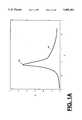
- FIG. 1Ashows an intensity distribution curve obtained from the embodiment of FIG. 1.
- FIG. 2shows a further currently preferred embodiment of the microprobe of the present invention.
- FIG. 3illustrates the principle of operation of the embodiment of FIG. 2.
- FIG. 4shows a cross-sectional view of a portion of FIG. 3.
- FIG. 5shows an intensity distribution curve obtained from the embodiment of FIG. 2.
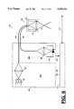
- FIG. 6shows the embodiment of FIG. 2 incorporated into a system having data collection and drive electronics.
- FIGS. 7A-7Cillustrate an embodiment of the present invention used in the probing of a semiconductor wafer.
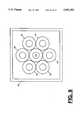
- FIG. 8illustrates a further currently preferred embodiment of the present invention utilizing several sense fibers.
- FIG. 9illustrates a system incorporating the embodiments shown in FIGS. 1 and 2.
- FIGS. 10A and 10Bshow two packing arrangements for a plurality of fibers.
- FIG. 11shows an array such as that shown in FIG. 10A wherein several source fibers are used at one time.
- FIG. 1shows a first preferred embodiment of confocal microprobe 100 of the present invention.
- Confocal microprobe 100comprises light source 105, lenses 107, 115, and 125, beam splitter 114, optical fiber 110, detector 130, reference detector 135, and chopper wheel 140.
- Light from source 105is focused by lens 107 to the first end 110a of optical fiber 110.
- Light exiting a second end 110b of optical fiber 110is focused by lens 115 to focal point 101.
- Source 105, detector 130, reference detector 135, and the associated optical componentstogether make up source/detector module 103.
- the term lensis not restricted to a single optical lens, but encompasses any one or more components used to focus radiation.
- each of the lenses 107, 115, and 124comprise a pair of identical doublet lenses arranged back to back to provide for a magnification of unity, so that the spot size of the focused light is the same as the size of end 110b of optical fiber 110.
- Other lens arrangements and magnificationsmay obviously be used.
- each lensis achromatic. With an achromatic lens all light from a polychromatic source such as an incandescent bulb, will be focused in nearly the same plane. If a source with a narrow wavelength band is used, an achromatic lens may not be necessary.
- Optical fiber 110has a core diameter in the range of approximately 100 ⁇ m, and a total diameter (core plus cladding) in the range of approximately 140 ⁇ m in a currently preferred embodiment. Additionally, optical fiber 110 may comprise a jacket and an additional hard covering. Also, in a currently preferred embodiment, light source 105 is a 71/2 watt incandescent light bulb, so that in a preferred embodiment optical fiber 110 operates in the transmission mode. Alternatively, other light sources, such as LEDs, laser diodes or gas lasers can be used. Additionally, although the present invention is described in conjunction with light, it will be appreciated that radiation outside of the visible range can also be used. In the embodiment of FIG. 1, focal point 101 is approximately 12 mm in front of lens 115.
- a portion of probe 102is present in the vicinity of focal point 101.
- a portion of the light reflected by any object to the right of lens 115will be reflected back through lens 115.
- Light which appears to come from focal point 101will be focused onto end 110b of fiber 110.
- Reflected light which does not appear to come from focal point 101will not be focused onto end 110b.
- the reflected light focused onto end 110bwill exit the first end 110a where it is reflected off of beam splitter 114 as shown by dashed line 116.
- the reflected lightis then focused by lens 125 into detector 130, which is shown as a photodetector in the figure.
- detector 130which is shown as a photodetector in the figure.
- detector 130is shown as a photodetector in the figure.
- detector 130is shown as a photodetector in the figure.
- detector 130is shown as a photodetector in the figure.
- CCD arrayfor example, can be used.
- Reference detector 135is used to eliminate the effect of any variations in light source 105 from the measurement of the reflected light from object 102.
- the use of reference detector 135is optional, and is not necessary in many cases.
- the reference detector 135is helpful for measurements which take place over a sufficiently long period of time such that draft in the output of light source 105 is a concern.
- Light exiting end 110b of optical fiber 110is approximately cone shaped as shown by dashed line 111. After passing through lens 115, the light resembles a converging cone 112a up to focal point 101 and then a diverging cone 112b. As an object or surface moves along the optical axis in the direction shown by arrow 113, for example, from right to left in the figure, light will be reflected back into the lens. Reflected light which appears to be emanating from the focal point will be refocused onto end 110b of the fiber. The closer an object is to focal point 101, the greater is the proportion of light reflected by it which appears to emanate from the focal point 101. Therefore, as the object moves from the right toward focal point 101, the intensity will increase.
- the intensity of the reflected light refocused onto end 110bwill be a maximum when the object is at focal point 101. As the object is moved further to the left, the intensity of reflected light refocused onto fiber end 110b will drop.
- the position of the objectcan be determined by noting the point at which a maximum intensity of reflected light occurs. This maximum intensity occurs when the object is at the focal point 101, which can readily be determined by a calibration routine. Assuming the position of confocal microprobe 100 is known relative to a reference position, the position of object 102 can thus be determined relative to the reference position.
- FIG. 1Ashows a graph of the intensity of light detected by detector 130 of FIG. 1 as an object or surface is moved as described above.
- Curve 150shows the intensity as a function of the object's distance from the lens. Peak 152 occurs when the object is positioned at focal point 101 of FIG. 1.
- One way of cutting down on this scattered lightis to first focus the light to a pinhole at the position where source 105 is shown and then focus the light from the pinhole via lens 107 to fiber end 110a. This eliminates scattered light from the area surrounding the fiber end 110a, i.e., from the fiber chuck or ferrule and surrounding housing material. This arrangement has the drawback that precise alignment of all components is necessary. Additionally, there may still be some scattered light from, for example. reflection from fiber end 110a as well as light scattered off of other components such as reference detector 135.
- a method of reducing the effect of noise from background lightis to chop the reflected light signal by means of chopper wheel 140. In this way, the light reflected from object 102 is an AC signal, whereas the background light is DC and can be filtered out.
- FIG. 2shows a further currently preferred embodiment of the present invention.
- Quasi-confocal microprobe 200comprises light source 205, lenses 207, 215, and 225, optical fibers 210 and 220, and detector 230. In general, these components are the same as the corresponding components of confocal microprobe 100 of FIG. 1.
- light from source 205is focused by lens 207 into the first end 210a of a first optical fiber 210, also referred to as the source fiber herein.
- the lightexits the second end 210b and is focused by lens 215 to a focal point.
- light reflected from an object to the right side of lens of 215is then focused by lens 215 to end 220b of a second optical fiber 220, also referred to as the sense fiber herein.
- the reflected lightthen exits end 220a of optical fiber 220 and is focused by lens 225 into detector 230.
- the true shape of the light distributionis not perfectly conical, since the light exiting 210b is not a perfect point source, but has a finite diameter.
- the various cone shapes shown in FIG. 3approximate the actual light distribution.
- the source lightwill be mostly confined within the cones 310b and 310c, with the greatest intensity at focal point 311 and decreasing intensity to either the left or the right-hand side.
- the cones 310b and 310cwill be referred to as the source cones herein.
- Focal point 321represents the focal point of sense fiber 220. In essence, focal point 321 is the position an object must be placed in order to be focused onto end 220b of sense fiber 220.
- any light passing through focal point 321 and passing through lens 215is focused to sense fiber end 220b.
- any radiation originating from a point to the left of focal point 321 and traveling left, through lens 215will also be focused on end 220b if its path, when extended to the right, would cross through focal point 321.
- cones 320b and 320crepresent areas of space in which all light meeting this criteria is focused onto end 220b of sense fiber 220.
- the cones 320b and 320cwill be referred to as the acceptance cones of sense fiber 220.
- FIG. 4shows a cross-sectional view of the source cone 310b and acceptance cone 320b taken through the portion marked in FIG. 3.
- FIG. 5shows a graph of the intensity of light detected by detector 230 of FIG. 2 as an object is moved in the direction indicated by arrow 313 of FIG. 3. This direction is denoted as the z-direction herein, as shown on the abscissa.
- the intensity of light as a function of the position in z of the object as it is moved from a distance towards the lens, I zis plotted along the ordinate. For example, assume object or surface 302, marked by an X, is moved from the position denoted 302a to position 302b. As the object or surface proceeds from right to left relative to the position of lens 215, the intensity of light increases from nearly zero intensity to a first peak 501.
- the intensity of radiationdrops off sharply, as the object exits the common volume 315b, traveling along line 303.
- the intensityreaches null point 502, and then increases as the object enters common volume 315a.
- the signalrises to a second peak 503.
- the intensitydecreases to the zero level.
- the null point 502occurs when the object is at the position labeled 301 in FIG. 3, referred to as the null position, which is in the focal plane of focal points 311 and 321.
- the objectwill be in neither the source cone 310 nor the acceptance cone 320.
- the regions denoted by the various conesare not perfectly conical, so that some light may be present in the region outside of the denoted source cone 310, and some reflected radiation outside of acceptance cone 320 may reach end 220b of sense fiber 220. Therefore, the intensity is not at a minimum for the entire length 303. Rather, the null point 502 occurs when the object is at null position 301 because null position 301 is in the focal plane of focal points 311 and 321, where the source and acceptance cones are narrowest.
- peak 501occurs when the object is approximately 11.2 mm from lens 215 and results in a photocurrent of approximately 5 ⁇ 10 -9 Amps.
- Null point 502occurs when the object is at a distance of approximately 11.7 mm.
- Peak 503occurs at approximately 11.9 mm, and results in a photocurrent of approximately 10 ⁇ 10 -9 Amps.
- the location of null point 502will depend upon the magnification and focal length of the lens.
- quasi-confocal microprobe 200is able to determine the position of an object with an accuracy of approximately ⁇ 5 ⁇ m or better.
- the null position 301occurs approximately at the focal point of the lens 215 using the current embodiment of back-to-back achromatic paired lens.
- the exact null position 301 of a quasi-confocal microprobe 200may vary depending on variations in the components such as lens variations, variations in optical fiber size, variations in system geometry, etc. However, the exact distance of null position 301 from a reference position can easily be determined by appropriate calibration.
- the position of an object relative to the reference positioncan readily be determined by moving the object relative to the lens along a portion of the distance between positions 302a and 302b, that is, along a line perpendicular to the focal plane of lens 215, and noting the position at which null point 502 occurs. This will be true regardless of the optical properties of The object.
- An object which is highly reflectivemay have higher peaks 501 and 503, for example, while an object which is relatively dark will have lower peaks 501 and 503. However, in all cases the central null 502 will always occur when an object is at the same distance from lens 215.
- the intensitycan be measured continuously as the object is moved, as described above, along a line perpendicular to the focal plane, i.e., at every position along the line, or the intensity can be measured at several discrete positions along the line.
- the method of the present inventionessentially determines position based upon the measured intensity at a plurality of positions along the line. Note that no image of the object needs to be formed in order to determine its position. Rather, in the present invention, only the intensity of reflected light is measured in order to detect null point 502.
- FIG. 6shows quasi-confocal microprobe 200 incorporated in system 600.
- System 600includes head unit 601 which comprises housing 602, lens 215, and the ends of optical fibers 210 and 220.
- Source/detector module 603includes light source 205, lens 207, lens 225, and detector 230.
- Source/detector module 603is coupled by connections 605 and 606 to the data collection/drive electronics unit 610.
- Note that light source 205is placed in compartment 603a of module 603, while detector 230 is placed in compartment 603b.
- the compartment 603bis designed so that no light from source 205, or from any other outside source such as room lighting, can reach detector 230.
- the ability to separate these componentseliminates the problem of background noise due to source light scattered from the various components as discussed earlier in relationship to confocal microprobe 100.
- head 601is moved back and forth relative to the object to be probed.
- a signal as described previously in relation to FIGS. 3 and 5is received by detector 230.
- the analog signalis converted to a digital signal by an analog to digital (A/D) converter and sent via connection 605 to data collection/drive unit 610.
- A/Danalog to digital
- head 601can be mounted in a fixed position, with the object to be probed mounted on a stage having, for example, a stepper motor to control the motion of the stage.
- head unit 601may be mounted such that it is movable. In the following discussion, the later embodiment will be described.
- Electronics unit 610is coupled via connection 612 to the motor drive (not shown) controlling the motion of head 601.
- electronics unit 610As electronics unit 610 receives the converted signal from detector 230, it will move head 601 up and down to collect data such as that shown in FIG. 5. Once the null point 502 of FIG. 5 is reached, the system will know the position of the object being probed in relation to head 601 since the position of head 601 relative to null position 301 will have been calibrated previously, as described above.
- quasi-confocal microprobe 200can be used to find the position of an object in relation to, for example, probe head 601 of FIG. 6.
- quasi-confocal microprobe 200can be used to form a topographical map of a substrate.
- a point-by-point searchcan be performed, to find the position of each point on the surface. For example, after finding the z position of a first point, either the substrate and/or head 601 can be moved in the x-y plane to another point, and the process repeated.
- the resolution of the topographical image thus formedwould depend upon the sampling rate in x and y which would be a matter of user choice.
- the resolutionis a function of the core and cladding size of the optical fibers, with a thin cladding in relation to the core preferred, and magnification of lens 215.
- a resolution of approximately ⁇ 2.51 ⁇ mis easily achievable in quasi-confocal microprobe 200 of the present invention.
- the microprobe of the present inventioncan also be used to form an image of a surface.
- head 601is set to a height above the surface so that the return signal through sense fiber 220 is at peak 501 of FIG. 5.
- the head 601then scans across the surface, with its z height position constantly adjusted so that it is always the same distance above the surface, i.e., always at the same point on peak 501.
- the return signalwill vary according to the reflectivity of the surface.
- a point-by-point map of the surface reflectivityis created to produce a surface image. It will be appreciated that the surface may not be planar.
- FIGS. 7A-7Cillustrate system 600 incorporated in wafer prober 700 for use in the probing of semiconductor wafer 701, as described in the background section.
- Wafer 701is placed on chuck 702 which sits atop Z stage 703.
- Z stage 703controls the z (up-down) motion of chuck 702.
- Z stage 703sits atop X-Y stage 704 which controls motion of the entire assembly in the x-y plane.
- Chuck 702, Z-stage 703, and X-Y stage 704will be referred to collectively as stage assembly 706.
- the modules 603 and 610are shown in a single enclosure.
- system 700comprises two microprobes having heads 601a and 601b, source cables 210a and 210b, and sense cables 220a and 220b. Either one or two light sources 205 and one or two detectors 230 are required, depending upon the configuration.
- the electronics unit 610controls the drive motors for the stages 703 and 704 via signals sent through coupling 612. Electronics unit 610 receives a signal from these stages indicating their position.
- Prober 700comprises probe card 705 having an array of probes 102.
- wafer 701is to be brought up to the tips 102a of probes 102 to allow probing of a die's probe pads.
- cantilever type probes 102are shown, it will be understood that the following applies to any type and number of probes for probing any one or more device die.
- the system 700will know in advance the approximate location of the probes 102 relative to stage assembly 706. As noted earlier, it is necessary to know precisely the location of the array of probes 102 in x and y, in order to align the probes 102 over the probe pads on wafer 701. It is also necessary to know precisely the z location of probes 102 in order to ensure that the wafer 701 is brought in contact with probes 120 to ensure electrical contact, without damaging wafer 701.
- X-Y stage 704is moved such that probe head 601a is underneath a reference surface, for example, the surface of the probe card 705 which is at a known location in z in relation to the probe 102.
- Z stage 703is moved in the z direction to find the null point as described previously. With this information, the system will know the approximate location in z of the probe tips 102a.
- Z stage 703is moved such that the expected z position of the tips 102a is in common volume 315b of FIG.
- X-Y stage 704is moved to a starting position based on the known configuration of the probe card such that the focal point 301a is in line with the approximate location of the first tip to be probed.
- X-Y stage 704is moved, for example, in a spiral type search, from the starting position, until the probe tip 102a enters common volume 315b, such that a return signal is detected.
- a probe tipwill cause a return signal even if focal point 301 a is not positioned at the x-y coordinates of the center of probe tip 102a.
- X-Y stage 704then scans in x and y at constant z, similar to the imaging mode described previously, except that this scan is carried out at a point to the left of peak 501, since the common volume 315b is wider, and a greater volume of space can be explored. By noting the points in the x, y scan where a return signal is detected, a rough image of the tip is produced, from which its x-y coordinates can be determined. Next, X-Y stage 704 is moved such that the focal point 301a is at the x, y coordinates of the center of probe tip 102a.
- Z stage 703is moved up to find null point 502, to determine the z-position of the probe tip 102a.
- the position of probe tip 102ahas been determined in x, y, and z.
- a further x-y scan in the imaging modecan be performed (i.e., microprobe 601a positioned such that the probe tip 102a is at the peak 501) to obtain more precise x-y data.
- numerous different computerized search routines using the signals received from the microprobe of the present inventioncan be used in conjunction with approximate starting locations to search for the probes in succession. Intelligent routines which learn as data are collected can be used to minimize search time.
- the location of an additional one or more probe tips 102amust be determined to determine the position of the array as a whole sufficient to ensure successful first die touch down. To achieve this, it is important to note that as an average over many probe locations the location of the array as a whole will be known more accurately than the location of an individual probe 102.
- probe head 601bis mounted above assembly 706, pointing downward.
- Microprobe 600bcan be used as an edge detector to find the edge of wafer 701, and as a surface profiler to profile the surface of wafer 701.
- the position of wafer 701 on chuck 702will be known approximately to within approximately ⁇ 150 ⁇ m depending upon the accuracy of the mechanical handling system which places wafer 701 on chuck 702.
- X-Y stage 704moves to assembly 706 to a position such that probe head 601b is above wafer 701 near its edge.
- Z stage 703positions chuck 702 such that the surface of wafer 702 is at the null position 301b, determined by detecting the null point 502 as described previously.
- the stage assembly 706 and therefore wafer 702is next moved to the left by X-Y stage 704.
- the null signal 502 of FIG. 5is returned, so long as the position of wafer 701 is such that the null position 301b is at the wafer surface.
- the edge of the waferwill cause a return signal to be detected (i.e., the z position of the wafer edge will be along the right peak 502 of FIG. 5), since the edge of wafer 701 is at a z position beyond the null position 301b.
- the return signalwill be caused by wafer chuck 702.
- the location of the edge of wafer 701can be determined to an accuracy of approximately within 8 ⁇ m.
- a profile of the wafer surfacei.e., the z location of the wafer surface, is needed in order to ensure proper contact between the probe tip and probe pad, as described earlier.
- assembly 706is moved such that wafer 701 is positioned underneath scan head 601b.
- the waferis moved up and down by z stage 703 until the null position 301b is at the wafer surface, determined by detecting the null point 502 of FIG. 5.
- the waferis then moved to subsequent positions by X-Y stage 704 and the process repeated.
- This profiling functionis essentially the same as the topographical mapping described earlier, except that typically, fewer points need be probed in order to obtain a profile compared with a topographical map. Typically, approximately 4-6 points of data at several spaced apart points on the wafer surface are sufficient to characterize the z position of the surface of the wafer.
- the position of the probe pads on wafer 701must now be determined.
- Each padis typically approximately 100 ⁇ m ⁇ 100 ⁇ m or smaller.
- the position of the probe padsis determined by machine vision system 710. This system utilizes a camera to provide an image of the probe pads. From this image, the position of the pads is determined in relation to machine vision system 710, which is known in relation to other system components and/or an arbitrary reference position. Thus, with the image obtained the position of the pads relative to the stage assembly 706 can be determined. Finally, the position of the probes 102 has been determined as described above. Electronics unit 610 then directs stage assembly 706 to a first die to be probed.
- X-Y stage 704positions the wafer in x-y, next, stage 703 moves chuck 702 and wafer 701 up to bring the first die to be probed into contact with probe tips 102a.
- stage 703moves chuck 702 and wafer 701 up to bring the first die to be probed into contact with probe tips 102a.
- the systemcan automatically move to the next die to be probed and continue the process.
- the position of the wafer's edgehas been determined with microprobe 600b. With this information, the system can be instructed to skip non-functional die near the wafer's edge, to minimize probing time.
- all die on wafer 701can be probed without requiring human alignment or other interaction with prober 700.
- probe card 705since visual alignment is not required, there is no need to maintain an opening in probe card 705 to allow for visual observation of the probing or to provide for some other means of alignment.
- the density of probes 102 on probe card 705is not limited to allow for alignment in the present invention.
- FIG. 8shows an end-on view of a portion of probe head 801, which is similar to probe head 601 except as described below. The view shown in FIG. 8 is looking into the probe head toward the ends of the optical fibers. As shown in FIG.
- six sense optical fibers 220are arranged hexagonally around source optical fiber 210. As shown, all of the fibers comprise a core and a cladding, as described earlier. In one embodiment the outputs of all six sense fibers 220 are fed into a single detector. Referring to FIG. 6, this embodiment essentially comprises a source module 603a and a detector module 603b, with the output of all six sense fibers 220 fed into the source detector module 603b. It has been found that this arrangement provides for a return signal that is essentially insensitive to direction. For example, in finding an edge of a wafer, the return signal is nearly identical regardless of the direction from which the wafer is approached. Additionally, on average, the return signal is increased in magnitude by approximately six times.
- this increased signal strengthwill provide for faster data collection, decreased noise sensitivity, and better detection of dark surfaces. It will be appreciated that other embodiments can be used using more or fewer sense cables 220. When a plurality of sense cables 220 are used, it is preferable to place them in a radially symmetric spacing.
- a plurality of sense fibers 220are provided wherein the output of each is fed into a separate detector.
- this embodimentcomprises a source module 603a, and six detector modules 603b, the output of each sense fiber 220 being fed into a separate one of the detector modules 603b.
- the individual detector modules 603bneed not be housed in physically separate compartments.
- each probe head 801can explore a much greater volume of space, and in essence is equivalent to six individual microprobes. Therefore, the amount of data collected at a time is increased approximately six fold. As described in conjunction with FIG.
- microprobe 600when a probe is searched for using a single source fiber 210 and a single sense fiber 220, microprobe 600 is positioned such that the probe tip 102a is beyond the null point i.e., in common volume 315b of FIG. 3.
- probe head 801Using probe head 801, a volume of space approximately six times greater than a single common volume 315b is explored at one time. This increased volume of space explored leads to a decreased time to find an object whose position is unknown.
- the signal from each of the six fibersis analyzed separately, and since each provides distinct information about the x-y location of the object causing a return signal, the object's location can be determined much more rapidly.
- probe head 80i having each sense fiber 220 coupled to a separate detectorcan, if desired, function as the earlier described embodiment wherein all sense fibers 220 are coupled to a single detector, by combining the signals together in the electronics.
- FIG. 9shows a further embodiment of the present invention having both a confocal and quasi-confocal probe.
- the embodiment in FIG. 9comprises a source/detector module 103, as shown in FIG. 1, having a light source, detector, lenses, and optionally a reference detector as described in relation to FIG. 1.
- Source fiber 110provides the illumination to probe head 601 and carries a return signal back to source/detector module 103. As shown, this fiber also serves as source fiber 210 as described previously for the quasi-confocal arrangement.
- sense fiber 220provides a return signal to detector module 603b.
- detector module 103will detect a return signal according to FIG.
- detector module 603bwill detect a return signal as shown in FIG. 5.
- the peak 152 of FIG. 1Awill occur at the same point as the null point 502 of FIG. 5.
- the combined confocal/quasi-confocal microprobe 900all the data collected with the microprobe 100 and all the data obtained with the microprobe 200 is obtained simultaneously, thus increasing the amount of information gathered. Additionally, since the peak of the confocal microprobe occurs at the same point as the null point of the quasi-confocal microprobe, a crosscheck of the data is obtained.
- the combined confocal/quasi-confocal microprobe 900can be utilized in conjunction with the microprobe described in relation to FIG. 8 having a plurality of sense fibers 220.
- a single source fiberacts as a source for plurality of sense fibers as described earlier.
- the sense fibers 220may be combined into a single detector, or may be coupled to separate detectors as described previously. Therefore, the embodiment where each of the sense fibers 220 is coupled to a separate detector, one set of data corresponding to that shown in FIG. 1 A, and six sets of data corresponding to that shown in FIG. 5, are obtained simultaneously.
- the number, arrangement, and functionalityare not limited to the embodiments shown and described above.
- the fiberscan be arranged in an array containing any number of fibers.
- the arrays in FIGS. 10A, 10B, and 11are not limited to the number of fibers shown.
- the fibershave not been labeled as each fiber may be any one of the types of fibers described herein.
- FIG. 10Ashows as an example, a hexagonal array, while FIG. 10B shows a rectangular array.
- each fiberis coupled to a source/detector module 103.
- any single fibercan act as a confocal microprobe.
- any one fibercan act as a source fiber 210 for one or more nearby sense fibers 20.
- any fibercan be used as a confocal microprobe, while any two or more fibers can be used as a quasi-confocal microprobe or a combined confocal and quasi-confocal microprobe as desired.
- arrayit is not necessary for each fiber to be coupled to a source or for each fiber to be coupled to a detector.
- arrayscan be configured with any combination of fibers of different functionality. For example, an array may have some fibers which function as source fibers only and some which function as sense fibers only, or an array may have some fibers which function as combined source/sense fibers and some which function as sense fibers only, etc.
- the probe headneed not be scanned in x and y as described previously. Rather, a surface can be profiled, or imaged, for example, by addressing the array electronically, turning on and off source fibers and detecting the return signals either in the confocal mode or quasi-confocal mode using one or more nearby fibers.
- a single source fiber in one area of the arrayis used at any one time so that illumination from several source fibers does not interfere with neighboring microprobes.
- several fiberscan be turned on simultaneously if they are separated by a sufficient distance.
- mathematical modelscan be used to deconvolve the signals from neighboring source fibers. For example, FIG.
- any sense fiber/detector 220/230can usefully detect signals from several nearby source fibers simultaneously by filtering the resulting signal, such as by frequency filtering when the source is pulse frequency encoded, for example.
- the lens of the present inventionfor example, lens 215 of probe head 601 produces a 1:1 magnification.
- the lenscould either magnify or reduce the source and reflected light.
- a reductionresults in a smaller spot size and a shallower depth of focus, resulting in a finer resolution.
- the tradeoffis that more data must be taken to determine z position and to produce an image.
- a magnificationresults in the opposite effects of a reduction.
- Other modificationscould be made by one of skill in the art, for example, substituting different types or combinations of lenses for those described herein. For example, it has been found that the lens in front of the detector (lens 125 of FIG. 1 and lens 225 of FIG.
- the light source and the detectormay be placed directly in the microprobe head.
- a light emitting diodefor example, can be placed at the position of end 210b of optical fiber 210.
- a photo detectorcould be placed at the position of optical fiber of end 220b to detect the return signal.
- a light emitting diodecould take the place of the end of source cable 210. With a plurality of detectors taking the place of the surrounding sense optical fibers 220.
- One drawback of this alternativeis that the source LED and the photo detectors are typically much larger than the respective ends of the optical fibers, thus limiting the resolution of the system.
- microprobe of the present inventionallows for automatic determination of, for example, probe tips, wafer, and pad position, thus allowing operator-free probing of a semiconductor wafer.
Landscapes
- Physics & Mathematics (AREA)
- General Physics & Mathematics (AREA)
- Length Measuring Devices By Optical Means (AREA)
Abstract
Description
Claims (24)
Priority Applications (1)
| Application Number | Priority Date | Filing Date | Title |
|---|---|---|---|
| US08/172,426US5450203A (en) | 1993-12-22 | 1993-12-22 | Method and apparatus for determining an objects position, topography and for imaging |
Applications Claiming Priority (1)
| Application Number | Priority Date | Filing Date | Title |
|---|---|---|---|
| US08/172,426US5450203A (en) | 1993-12-22 | 1993-12-22 | Method and apparatus for determining an objects position, topography and for imaging |
Publications (1)
| Publication Number | Publication Date |
|---|---|
| US5450203Atrue US5450203A (en) | 1995-09-12 |
Family
ID=22627645
Family Applications (1)
| Application Number | Title | Priority Date | Filing Date |
|---|---|---|---|
| US08/172,426Expired - LifetimeUS5450203A (en) | 1993-12-22 | 1993-12-22 | Method and apparatus for determining an objects position, topography and for imaging |
Country Status (1)
| Country | Link |
|---|---|
| US (1) | US5450203A (en) |
Cited By (130)
| Publication number | Priority date | Publication date | Assignee | Title |
|---|---|---|---|---|
| DE19537586A1 (en)* | 1995-10-09 | 1997-04-10 | Schleifmittelwerk P Lapport & | Surface and volume measuring instrument using confocal image |
| US5771091A (en)* | 1994-12-07 | 1998-06-23 | Phone-Or Ltd | Sensor and a method for measuring distances to, and/or physical properties of, a medium |
| US5831797A (en)* | 1997-07-23 | 1998-11-03 | Seagate Technology, Inc. | Slider with mesa for optical disc data storage system |
| DE19722607A1 (en)* | 1997-05-30 | 1998-12-03 | Michael F Braun | Surface measurement of esp. textile fabrics to determine weave density |
| US5870362A (en)* | 1997-06-20 | 1999-02-09 | Seagate Technology, Inc. | Slider for optical disc data storage system |
| US5917788A (en)* | 1997-03-10 | 1999-06-29 | Seagate Technology, Inc. | Lens for optical data storage system |
| US5930434A (en)* | 1997-05-15 | 1999-07-27 | Seagate Technology,. Inc. | Optical disc data storage system using optical waveguide |
| WO1999044089A1 (en)* | 1998-02-26 | 1999-09-02 | The General Hospital Corporation | Confocal microscopy with multi-spectral encoding |
| US6023378A (en)* | 1998-01-20 | 2000-02-08 | Seagate Technology, Inc. | Optical data storage system with improved head lens assembly |
| US6084846A (en)* | 1998-06-03 | 2000-07-04 | Seagate Technology, Inc. | Liquid immersion lens for optical data storage |
| US6096567A (en)* | 1997-12-01 | 2000-08-01 | Electroglas, Inc. | Method and apparatus for direct probe sensing |
| US6101155A (en)* | 1997-08-14 | 2000-08-08 | Seagate Technology, Inc. | Lens for optical data storage system |
| US6181474B1 (en) | 1999-03-22 | 2001-01-30 | Kovex Corporation | Scanning confocal microscope with objective lens position tracking |
| US6211532B1 (en)* | 1997-01-13 | 2001-04-03 | Canon Kabushiki Kaisha | Microprobe chip for detecting evanescent waves probe provided with the microprobe chip and evanescent wave detector, nearfield scanning optical microscope, and information regenerator provided with the microprobe chip |
| US6249621B1 (en)* | 1995-05-08 | 2001-06-19 | Intest Sunnyvale Corporation | Optical fiber interface for integrated circuit test system |
| US6301004B1 (en)* | 2000-05-31 | 2001-10-09 | Lj Laboratories, L.L.C. | Apparatus and method for measuring optical characteristics of an object |
| US6327241B1 (en) | 1997-04-08 | 2001-12-04 | Seagate Technology Llc | Optical data storage system with lens mount |
| US6357330B1 (en)* | 1999-01-07 | 2002-03-19 | Intel Corporation | Method and apparatus for cutting a wafer |
| US6362888B1 (en) | 1999-12-23 | 2002-03-26 | Lj Laboratories, L.L.C. | Spectrometer assembly |
| US6373573B1 (en) | 2000-03-13 | 2002-04-16 | Lj Laboratories L.L.C. | Apparatus for measuring optical characteristics of a substrate and pigments applied thereto |
| US6414750B2 (en) | 2000-01-10 | 2002-07-02 | Lj Laboratories, L.L.C. | Spectrometric apparatus and method for measuring optical characteristics of an object |
| US6417917B1 (en) | 1996-01-02 | 2002-07-09 | Lj Laboratories, Llc | Apparatus and method for measuring optical characteristics of an object |
| US6445447B1 (en) | 1997-10-27 | 2002-09-03 | Seagate Technology Llc | Near field optical certifying head for disc asperity mapping |
| US6449041B1 (en) | 1997-07-01 | 2002-09-10 | Lj Laboratories, Llc | Apparatus and method for measuring optical characteristics of an object |
| US6490038B1 (en) | 1996-01-02 | 2002-12-03 | Lj Laboratories Llc | Apparatus and method for measuring optical characteristics of an object |
| US6501542B2 (en) | 1998-06-30 | 2002-12-31 | Lj Laboratories, Llc | Apparatus and method for measuring optical characteristics of an object |
| US20030028100A1 (en)* | 2001-05-01 | 2003-02-06 | Tearney Guillermo J. | Method and apparatus for determination of atherosclerotic plaque type by measurement of tissue optical properties |
| US6519037B2 (en) | 1999-12-23 | 2003-02-11 | Lj Laboratories, Llc | Spectrometer having optical unit including a randomized fiber optic implement |
| US6538726B2 (en) | 1998-07-10 | 2003-03-25 | Lj Laboratories, Llc | Apparatus and method for measuring optical characteristics of an object |
| US6573984B2 (en) | 1998-06-30 | 2003-06-03 | Lj Laboratories Llc | Apparatus and method for measuring optical characteristics of teeth |
| US6688743B1 (en) | 1998-02-17 | 2004-02-10 | Seagate Technology | Method and apparatus to determine fly height of a recording head |
| US6726476B2 (en) | 1997-01-02 | 2004-04-27 | Jjl Technologies Llc | Apparatus and method for measuring optical characteristics of teeth |
| US20040081625A1 (en)* | 2002-10-21 | 2004-04-29 | Schering Corporation | Nasal formulations for the treatment of allergies |
| US6747795B2 (en) | 2000-06-30 | 2004-06-08 | The General Hospital Corporation | Fiber-coupled multiplexed confocal microscope |
| US6831781B2 (en) | 1998-02-26 | 2004-12-14 | The General Hospital Corporation | Confocal microscopy with multi-spectral encoding and system and apparatus for spectroscopically encoded confocal microscopy |
| WO2005022130A1 (en) | 2003-08-27 | 2005-03-10 | Teraview Limited | Method and apparatus for investigating a non-planar sample |
| US6870616B2 (en) | 1998-06-30 | 2005-03-22 | Jjl Technologies Llc | Spectrometer apparatus for determining an optical characteristic of an object or material having one or more sensors for determining a physical position or non-color property |
| WO2005080947A1 (en)* | 2004-02-13 | 2005-09-01 | Teraview Limited | Terahertz probe array imaging system |
| US20050280828A1 (en)* | 2001-10-16 | 2005-12-22 | The General Hospital Corporation | Systems and methods for imaging a sample |
| US7018204B2 (en) | 1996-01-02 | 2006-03-28 | Jjl Technologies Llc | Methods for determining optical characteristics of dental objects using an imaging element and a spectrometer apparatus |
| US7069186B2 (en) | 1998-07-09 | 2006-06-27 | Jung Wayne D | Method for remotely controlling a spectral measurement device utilizing predicted service life or a remotely provided software upgrade including color reference or shade guide data |
| DE102005052743A1 (en)* | 2005-11-04 | 2007-05-10 | Precitec Optronik Gmbh | Measuring system for the measurement of boundary surfaces or surfaces of workpieces |
| US7231243B2 (en) | 2000-10-30 | 2007-06-12 | The General Hospital Corporation | Optical methods for tissue analysis |
| US7298483B2 (en) | 2002-02-21 | 2007-11-20 | Vita Zahnfabrik H. Rauter Gmbh & Co. Kg | Miniaturized system and method for measuring optical characteristics |
| US7310150B2 (en) | 2002-01-11 | 2007-12-18 | The General Hospital Corporation | Apparatus and method for low coherence ranging |
| US7355716B2 (en) | 2002-01-24 | 2008-04-08 | The General Hospital Corporation | Apparatus and method for ranging and noise reduction of low coherence interferometry LCI and optical coherence tomography OCT signals by parallel detection of spectral bands |
| US7362116B1 (en) | 2005-11-09 | 2008-04-22 | Electroglas, Inc. | Method for probing impact sensitive and thin layered substrate |
| US20080097225A1 (en)* | 2006-10-19 | 2008-04-24 | The General Hospital Corporation | Apparatus and method for obtaining and providing imaging information associated with at least one portion of a sample, and effecting such portion(s) |
| US7366376B2 (en) | 2004-09-29 | 2008-04-29 | The General Hospital Corporation | System and method for optical coherence imaging |
| US7365859B2 (en) | 2004-09-10 | 2008-04-29 | The General Hospital Corporation | System and method for optical coherence imaging |
| US7382949B2 (en) | 2004-11-02 | 2008-06-03 | The General Hospital Corporation | Fiber-optic rotational device, optical system and method for imaging a sample |
| US7418169B2 (en) | 2006-02-01 | 2008-08-26 | The General Hospital Corporation | Apparatus for controlling at least one of at least two sections of at least one fiber |
| US7447408B2 (en) | 2004-07-02 | 2008-11-04 | The General Hospital Corproation | Imaging system and related techniques |
| DE10161486B4 (en)* | 2001-12-14 | 2008-11-13 | Carl Mahr Holding Gmbh | Confocal line sensor |
| US7519096B2 (en) | 2003-06-06 | 2009-04-14 | The General Hospital Corporation | Process and apparatus for a wavelength tuning source |
| US7538859B2 (en) | 2006-02-01 | 2009-05-26 | The General Hospital Corporation | Methods and systems for monitoring and obtaining information of at least one portion of a sample using conformal laser therapy procedures, and providing electromagnetic radiation thereto |
| US7551293B2 (en) | 2003-11-28 | 2009-06-23 | The General Hospital Corporation | Method and apparatus for three-dimensional spectrally encoded imaging |
| US7567349B2 (en) | 2003-03-31 | 2009-07-28 | The General Hospital Corporation | Speckle reduction in optical coherence tomography by path length encoded angular compounding |
| US7586608B1 (en)* | 2003-04-07 | 2009-09-08 | Luxtera, Inc. | Wafer-level testing of optical and optoelectronic chips |
| US7643153B2 (en) | 2003-01-24 | 2010-01-05 | The General Hospital Corporation | Apparatus and method for ranging and noise reduction of low coherence interferometry LCI and optical coherence tomography OCT signals by parallel detection of spectral bands |
| US7733497B2 (en) | 2003-10-27 | 2010-06-08 | The General Hospital Corporation | Method and apparatus for performing optical imaging using frequency-domain interferometry |
| US7742173B2 (en) | 2006-04-05 | 2010-06-22 | The General Hospital Corporation | Methods, arrangements and systems for polarization-sensitive optical frequency domain imaging of a sample |
| US7761139B2 (en) | 2003-01-24 | 2010-07-20 | The General Hospital Corporation | System and method for identifying tissue using low-coherence interferometry |
| US7782464B2 (en) | 2006-05-12 | 2010-08-24 | The General Hospital Corporation | Processes, arrangements and systems for providing a fiber layer thickness map based on optical coherence tomography images |
| US7796270B2 (en) | 2006-01-10 | 2010-09-14 | The General Hospital Corporation | Systems and methods for generating data based on one or more spectrally-encoded endoscopy techniques |
| US7843572B2 (en) | 2005-09-29 | 2010-11-30 | The General Hospital Corporation | Method and apparatus for optical imaging via spectral encoding |
| US7859679B2 (en) | 2005-05-31 | 2010-12-28 | The General Hospital Corporation | System, method and arrangement which can use spectral encoding heterodyne interferometry techniques for imaging |
| US7889348B2 (en) | 2005-10-14 | 2011-02-15 | The General Hospital Corporation | Arrangements and methods for facilitating photoluminescence imaging |
| US7911621B2 (en) | 2007-01-19 | 2011-03-22 | The General Hospital Corporation | Apparatus and method for controlling ranging depth in optical frequency domain imaging |
| US7920271B2 (en) | 2006-08-25 | 2011-04-05 | The General Hospital Corporation | Apparatus and methods for enhancing optical coherence tomography imaging using volumetric filtering techniques |
| US7933021B2 (en) | 2007-10-30 | 2011-04-26 | The General Hospital Corporation | System and method for cladding mode detection |
| US7949019B2 (en) | 2007-01-19 | 2011-05-24 | The General Hospital | Wavelength tuning source based on a rotatable reflector |
| US7982879B2 (en) | 2006-02-24 | 2011-07-19 | The General Hospital Corporation | Methods and systems for performing angle-resolved fourier-domain optical coherence tomography |
| US7995210B2 (en) | 2004-11-24 | 2011-08-09 | The General Hospital Corporation | Devices and arrangements for performing coherence range imaging using a common path interferometer |
| US8018598B2 (en) | 2004-05-29 | 2011-09-13 | The General Hospital Corporation | Process, system and software arrangement for a chromatic dispersion compensation using reflective layers in optical coherence tomography (OCT) imaging |
| US8040608B2 (en) | 2007-08-31 | 2011-10-18 | The General Hospital Corporation | System and method for self-interference fluorescence microscopy, and computer-accessible medium associated therewith |
| US8045177B2 (en) | 2007-04-17 | 2011-10-25 | The General Hospital Corporation | Apparatus and methods for measuring vibrations using spectrally-encoded endoscopy |
| US8081316B2 (en) | 2004-08-06 | 2011-12-20 | The General Hospital Corporation | Process, system and software arrangement for determining at least one location in a sample using an optical coherence tomography |
| US8097864B2 (en) | 2009-01-26 | 2012-01-17 | The General Hospital Corporation | System, method and computer-accessible medium for providing wide-field superresolution microscopy |
| US8115919B2 (en) | 2007-05-04 | 2012-02-14 | The General Hospital Corporation | Methods, arrangements and systems for obtaining information associated with a sample using optical microscopy |
| US8145018B2 (en) | 2006-01-19 | 2012-03-27 | The General Hospital Corporation | Apparatus for obtaining information for a structure using spectrally-encoded endoscopy techniques and methods for producing one or more optical arrangements |
| US8175685B2 (en) | 2006-05-10 | 2012-05-08 | The General Hospital Corporation | Process, arrangements and systems for providing frequency domain imaging of a sample |
| US8208995B2 (en) | 2004-08-24 | 2012-06-26 | The General Hospital Corporation | Method and apparatus for imaging of vessel segments |
| US8351665B2 (en) | 2005-04-28 | 2013-01-08 | The General Hospital Corporation | Systems, processes and software arrangements for evaluating information associated with an anatomical structure by an optical coherence ranging technique |
| US8593619B2 (en) | 2008-05-07 | 2013-11-26 | The General Hospital Corporation | System, method and computer-accessible medium for tracking vessel motion during three-dimensional coronary artery microscopy |
| US8721077B2 (en) | 2011-04-29 | 2014-05-13 | The General Hospital Corporation | Systems, methods and computer-readable medium for determining depth-resolved physical and/or optical properties of scattering media by analyzing measured data over a range of depths |
| US8804126B2 (en) | 2010-03-05 | 2014-08-12 | The General Hospital Corporation | Systems, methods and computer-accessible medium which provide microscopic images of at least one anatomical structure at a particular resolution |
| US8861910B2 (en) | 2008-06-20 | 2014-10-14 | The General Hospital Corporation | Fused fiber optic coupler arrangement and method for use thereof |
| US8922781B2 (en) | 2004-11-29 | 2014-12-30 | The General Hospital Corporation | Arrangements, devices, endoscopes, catheters and methods for performing optical imaging by simultaneously illuminating and detecting multiple points on a sample |
| US8937724B2 (en) | 2008-12-10 | 2015-01-20 | The General Hospital Corporation | Systems and methods for extending imaging depth range of optical coherence tomography through optical sub-sampling |
| US8965487B2 (en) | 2004-08-24 | 2015-02-24 | The General Hospital Corporation | Process, system and software arrangement for measuring a mechanical strain and elastic properties of a sample |
| US9060689B2 (en) | 2005-06-01 | 2015-06-23 | The General Hospital Corporation | Apparatus, method and system for performing phase-resolved optical frequency domain imaging |
| US9069130B2 (en) | 2010-05-03 | 2015-06-30 | The General Hospital Corporation | Apparatus, method and system for generating optical radiation from biological gain media |
| US9087368B2 (en) | 2006-01-19 | 2015-07-21 | The General Hospital Corporation | Methods and systems for optical imaging or epithelial luminal organs by beam scanning thereof |
| US9178330B2 (en) | 2009-02-04 | 2015-11-03 | The General Hospital Corporation | Apparatus and method for utilization of a high-speed optical wavelength tuning source |
| US9176319B2 (en) | 2007-03-23 | 2015-11-03 | The General Hospital Corporation | Methods, arrangements and apparatus for utilizing a wavelength-swept laser using angular scanning and dispersion procedures |
| US9254089B2 (en) | 2008-07-14 | 2016-02-09 | The General Hospital Corporation | Apparatus and methods for facilitating at least partial overlap of dispersed ration on at least one sample |
| US9295391B1 (en) | 2000-11-10 | 2016-03-29 | The General Hospital Corporation | Spectrally encoded miniature endoscopic imaging probe |
| US9330092B2 (en) | 2011-07-19 | 2016-05-03 | The General Hospital Corporation | Systems, methods, apparatus and computer-accessible-medium for providing polarization-mode dispersion compensation in optical coherence tomography |
| US9332942B2 (en) | 2008-01-28 | 2016-05-10 | The General Hospital Corporation | Systems, processes and computer-accessible medium for providing hybrid flourescence and optical coherence tomography imaging |
| US9341783B2 (en) | 2011-10-18 | 2016-05-17 | The General Hospital Corporation | Apparatus and methods for producing and/or providing recirculating optical delay(s) |
| US9351642B2 (en) | 2009-03-12 | 2016-05-31 | The General Hospital Corporation | Non-contact optical system, computer-accessible medium and method for measurement at least one mechanical property of tissue using coherent speckle technique(s) |
| US9375158B2 (en) | 2007-07-31 | 2016-06-28 | The General Hospital Corporation | Systems and methods for providing beam scan patterns for high speed doppler optical frequency domain imaging |
| US9415550B2 (en) | 2012-08-22 | 2016-08-16 | The General Hospital Corporation | System, method, and computer-accessible medium for fabrication miniature endoscope using soft lithography |
| US9441948B2 (en) | 2005-08-09 | 2016-09-13 | The General Hospital Corporation | Apparatus, methods and storage medium for performing polarization-based quadrature demodulation in optical coherence tomography |
| US9510758B2 (en) | 2010-10-27 | 2016-12-06 | The General Hospital Corporation | Apparatus, systems and methods for measuring blood pressure within at least one vessel |
| US9557154B2 (en) | 2010-05-25 | 2017-01-31 | The General Hospital Corporation | Systems, devices, methods, apparatus and computer-accessible media for providing optical imaging of structures and compositions |
| US9629528B2 (en) | 2012-03-30 | 2017-04-25 | The General Hospital Corporation | Imaging system, method and distal attachment for multidirectional field of view endoscopy |
| US9668652B2 (en) | 2013-07-26 | 2017-06-06 | The General Hospital Corporation | System, apparatus and method for utilizing optical dispersion for fourier-domain optical coherence tomography |
| US9733460B2 (en) | 2014-01-08 | 2017-08-15 | The General Hospital Corporation | Method and apparatus for microscopic imaging |
| US9777053B2 (en) | 2006-02-08 | 2017-10-03 | The General Hospital Corporation | Methods, arrangements and systems for obtaining information associated with an anatomical sample using optical microscopy |
| US9784681B2 (en) | 2013-05-13 | 2017-10-10 | The General Hospital Corporation | System and method for efficient detection of the phase and amplitude of a periodic modulation associated with self-interfering fluorescence |
| US9795301B2 (en) | 2010-05-25 | 2017-10-24 | The General Hospital Corporation | Apparatus, systems, methods and computer-accessible medium for spectral analysis of optical coherence tomography images |
| US9897538B2 (en) | 2001-04-30 | 2018-02-20 | The General Hospital Corporation | Method and apparatus for improving image clarity and sensitivity in optical coherence tomography using dynamic feedback to control focal properties and coherence gating |
| US10117576B2 (en) | 2013-07-19 | 2018-11-06 | The General Hospital Corporation | System, method and computer accessible medium for determining eye motion by imaging retina and providing feedback for acquisition of signals from the retina |
| US10228556B2 (en) | 2014-04-04 | 2019-03-12 | The General Hospital Corporation | Apparatus and method for controlling propagation and/or transmission of electromagnetic radiation in flexible waveguide(s) |
| US10241028B2 (en) | 2011-08-25 | 2019-03-26 | The General Hospital Corporation | Methods, systems, arrangements and computer-accessible medium for providing micro-optical coherence tomography procedures |
| US10285568B2 (en) | 2010-06-03 | 2019-05-14 | The General Hospital Corporation | Apparatus and method for devices for imaging structures in or at one or more luminal organs |
| US10426548B2 (en) | 2006-02-01 | 2019-10-01 | The General Hosppital Corporation | Methods and systems for providing electromagnetic radiation to at least one portion of a sample using conformal laser therapy procedures |
| US10478072B2 (en) | 2013-03-15 | 2019-11-19 | The General Hospital Corporation | Methods and system for characterizing an object |
| US10534129B2 (en) | 2007-03-30 | 2020-01-14 | The General Hospital Corporation | System and method providing intracoronary laser speckle imaging for the detection of vulnerable plaque |
| US10736494B2 (en) | 2014-01-31 | 2020-08-11 | The General Hospital Corporation | System and method for facilitating manual and/or automatic volumetric imaging with real-time tension or force feedback using a tethered imaging device |
| US20200326224A1 (en)* | 2019-04-10 | 2020-10-15 | The Boeing Company | Non-Contact Time-of-Flight Fuel Level Sensor Using Plastic Optical Fiber |
| US10893806B2 (en) | 2013-01-29 | 2021-01-19 | The General Hospital Corporation | Apparatus, systems and methods for providing information regarding the aortic valve |
| US10912462B2 (en) | 2014-07-25 | 2021-02-09 | The General Hospital Corporation | Apparatus, devices and methods for in vivo imaging and diagnosis |
| US11123047B2 (en) | 2008-01-28 | 2021-09-21 | The General Hospital Corporation | Hybrid systems and methods for multi-modal acquisition of intravascular imaging data and counteracting the effects of signal absorption in blood |
| US11179028B2 (en) | 2013-02-01 | 2021-11-23 | The General Hospital Corporation | Objective lens arrangement for confocal endomicroscopy |
| US11452433B2 (en) | 2013-07-19 | 2022-09-27 | The General Hospital Corporation | Imaging apparatus and method which utilizes multidirectional field of view endoscopy |
| US11490826B2 (en) | 2009-07-14 | 2022-11-08 | The General Hospital Corporation | Apparatus, systems and methods for measuring flow and pressure within a vessel |
| US11490797B2 (en) | 2012-05-21 | 2022-11-08 | The General Hospital Corporation | Apparatus, device and method for capsule microscopy |
Citations (9)
| Publication number | Priority date | Publication date | Assignee | Title |
|---|---|---|---|---|
| US4325638A (en)* | 1979-04-27 | 1982-04-20 | Tokyo Kogaku Kikai Kabushiki Kaisha | Electro-optical distance measuring apparatus |
| US4581529A (en)* | 1983-08-15 | 1986-04-08 | At&T Bell Laboratories | Read/write system for optical disc apparatus with fiber optics |
| US4692023A (en)* | 1983-07-30 | 1987-09-08 | Tokyo Kagaku Kikai Kabushiki Kaisha | Optical adapter for a light-wave rangefinder |
| US4806016A (en)* | 1987-05-15 | 1989-02-21 | Rosemount Inc. | Optical displacement sensor |
| US4812003A (en)* | 1987-11-10 | 1989-03-14 | Molex Incorporated | Optic sensing assembly |
| US4991971A (en)* | 1989-02-13 | 1991-02-12 | United Technologies Corporation | Fiber optic scatterometer for measuring optical surface roughness |
| NL9001202A (en)* | 1990-05-25 | 1991-12-16 | Philips Nv | Confocal detector scanning system for compact disc player - uses fibre=optic assembly in place of conventional pinhole diaphragm |
| US5120953A (en)* | 1988-07-13 | 1992-06-09 | Harris Martin R | Scanning confocal microscope including a single fibre for transmitting light to and receiving light from an object |
| US5319442A (en)* | 1991-08-20 | 1994-06-07 | Renishaw Metrology Limited | Optical inspection probe |
- 1993
- 1993-12-22USUS08/172,426patent/US5450203A/ennot_activeExpired - Lifetime
Patent Citations (9)
| Publication number | Priority date | Publication date | Assignee | Title |
|---|---|---|---|---|
| US4325638A (en)* | 1979-04-27 | 1982-04-20 | Tokyo Kogaku Kikai Kabushiki Kaisha | Electro-optical distance measuring apparatus |
| US4692023A (en)* | 1983-07-30 | 1987-09-08 | Tokyo Kagaku Kikai Kabushiki Kaisha | Optical adapter for a light-wave rangefinder |
| US4581529A (en)* | 1983-08-15 | 1986-04-08 | At&T Bell Laboratories | Read/write system for optical disc apparatus with fiber optics |
| US4806016A (en)* | 1987-05-15 | 1989-02-21 | Rosemount Inc. | Optical displacement sensor |
| US4812003A (en)* | 1987-11-10 | 1989-03-14 | Molex Incorporated | Optic sensing assembly |
| US5120953A (en)* | 1988-07-13 | 1992-06-09 | Harris Martin R | Scanning confocal microscope including a single fibre for transmitting light to and receiving light from an object |
| US4991971A (en)* | 1989-02-13 | 1991-02-12 | United Technologies Corporation | Fiber optic scatterometer for measuring optical surface roughness |
| NL9001202A (en)* | 1990-05-25 | 1991-12-16 | Philips Nv | Confocal detector scanning system for compact disc player - uses fibre=optic assembly in place of conventional pinhole diaphragm |
| US5319442A (en)* | 1991-08-20 | 1994-06-07 | Renishaw Metrology Limited | Optical inspection probe |
Non-Patent Citations (4)
| Title |
|---|
| Article, "Cataract Fiber Optic Probe," Applied Optics, 32, 21, pp. 3823-3824. Jul. 20, 1993. |
| Article, Cataract Fiber Optic Probe, Applied Optics, 32, 21, pp. 3823 3824. Jul. 20, 1993.* |
| Daoning Su, Denis R. Hall and Julian D. C. Jones, "Workpeice Position Sensing By Means Of A Fiber Optical Beam Delivery System", Optical Engineering, Aug. 1993, vol. 32 No. 8, pp. 1923-1826. |
| Daoning Su, Denis R. Hall and Julian D. C. Jones, Workpeice Position Sensing By Means Of A Fiber Optical Beam Delivery System , Optical Engineering, Aug. 1993, vol. 32 No. 8, pp. 1923 1826.* |
Cited By (251)
| Publication number | Priority date | Publication date | Assignee | Title |
|---|---|---|---|---|
| US5771091A (en)* | 1994-12-07 | 1998-06-23 | Phone-Or Ltd | Sensor and a method for measuring distances to, and/or physical properties of, a medium |
| US6249621B1 (en)* | 1995-05-08 | 2001-06-19 | Intest Sunnyvale Corporation | Optical fiber interface for integrated circuit test system |
| DE19537586A1 (en)* | 1995-10-09 | 1997-04-10 | Schleifmittelwerk P Lapport & | Surface and volume measuring instrument using confocal image |
| DE19537586C2 (en)* | 1995-10-09 | 2002-03-28 | Schleifmittelwerk P Lapport & | Measuring device for determining surfaces, surface profiles and volumes |
| US7400404B2 (en) | 1996-01-02 | 2008-07-15 | Jjl Technologies Llc | Apparatus and method for measuring color |
| US7538878B2 (en) | 1996-01-02 | 2009-05-26 | Jjl Technologies Llc | Apparatus and method for measuring optical characteristics of an object |
| US7240839B2 (en) | 1996-01-02 | 2007-07-10 | Jjl Technologies Llc | Color measurement apparatus operable as a pointing device, a computer display measurement device and a printer output measurement device |
| US6417917B1 (en) | 1996-01-02 | 2002-07-09 | Lj Laboratories, Llc | Apparatus and method for measuring optical characteristics of an object |
| US6490038B1 (en) | 1996-01-02 | 2002-12-03 | Lj Laboratories Llc | Apparatus and method for measuring optical characteristics of an object |
| US6915955B2 (en) | 1996-01-02 | 2005-07-12 | Jjl Technologies Llc | Apparatus for determining multi-bit data via light received by a light receiver and coupled to spectral sensors that measure light in spectral bands |
| US7244122B2 (en) | 1996-01-02 | 2007-07-17 | Jjl Technologies Llc | Methods for determining optical characteristics of dental objects |
| US7018204B2 (en) | 1996-01-02 | 2006-03-28 | Jjl Technologies Llc | Methods for determining optical characteristics of dental objects using an imaging element and a spectrometer apparatus |
| US8159666B2 (en) | 1996-01-02 | 2012-04-17 | Jjl Technologies Llc | Apparatus and method for measuring color |
| US7682150B2 (en) | 1996-01-02 | 2010-03-23 | Jjl Technologies Llc | Method for preparing a dental prosthesis based on electronically determined image and color/shade data and based on telephone communication |
| US7113283B2 (en) | 1996-01-02 | 2006-09-26 | Jjl Technologies Llc | Apparatus and method for measuring color |
| US8817243B2 (en) | 1996-01-02 | 2014-08-26 | 511 Innovations, Inc. | Apparatus and method for measuring color |
| US7097450B2 (en) | 1996-01-02 | 2006-08-29 | Jjl Technologies Llc | Methods for determining color or shade information of a dental object using an image generation device without operator identification of the position of a reference implement in the field of view of the image generation device |
| US8792097B2 (en) | 1996-01-02 | 2014-07-29 | 511 Innovations, Inc. | Systems for applying pigment to a substrate with a spectrophotometer integral to the system |
| US20030202184A1 (en)* | 1997-01-02 | 2003-10-30 | Jung Wayne D. | Apparatus and method for measuring optical characteristics of an object |
| US6726476B2 (en) | 1997-01-02 | 2004-04-27 | Jjl Technologies Llc | Apparatus and method for measuring optical characteristics of teeth |
| US20060017929A1 (en)* | 1997-01-02 | 2006-01-26 | Jung Wayne D | Apparatus and method for measuring optical characteristics of an object |
| US8472012B2 (en) | 1997-01-02 | 2013-06-25 | Jjl Technologies Llc | Apparatus having a first optical sensor making a first measurement to detect position and a second optical sensor making a second measurement |
| US7110096B2 (en) | 1997-01-02 | 2006-09-19 | Jjl Technologies Llc | Method for determing optical characteristics through a protective barrier |
| US6570654B2 (en) | 1997-01-02 | 2003-05-27 | Lj Laboratories Llc | Apparatus and method for measuring optical characteristics of an object |
| US6381017B2 (en) | 1997-01-02 | 2002-04-30 | Lj Laboratories, L.L.C. | Apparatus and method for measuring optical characteristics of an object |
| US7397541B2 (en) | 1997-01-02 | 2008-07-08 | Ssl Technologies Llc | Apparatus and method for measuring optical characteristics of an object |
| US6950189B2 (en) | 1997-01-02 | 2005-09-27 | Jjl Technologies Llc | Apparatus and method for measuring optical characteristics of an object |
| US8998613B2 (en) | 1997-01-02 | 2015-04-07 | 511 Innovations Inc. | Apparatus and method for measuring optical characteristics using a camera and a calibration chart imaged with the camera |
| US6211532B1 (en)* | 1997-01-13 | 2001-04-03 | Canon Kabushiki Kaisha | Microprobe chip for detecting evanescent waves probe provided with the microprobe chip and evanescent wave detector, nearfield scanning optical microscope, and information regenerator provided with the microprobe chip |
| US6157598A (en)* | 1997-03-10 | 2000-12-05 | Seagate Technology Llc | Lens for optical data storage system |
| US5917788A (en)* | 1997-03-10 | 1999-06-29 | Seagate Technology, Inc. | Lens for optical data storage system |
| US6327241B1 (en) | 1997-04-08 | 2001-12-04 | Seagate Technology Llc | Optical data storage system with lens mount |
| US5930434A (en)* | 1997-05-15 | 1999-07-27 | Seagate Technology,. Inc. | Optical disc data storage system using optical waveguide |
| DE19722607A1 (en)* | 1997-05-30 | 1998-12-03 | Michael F Braun | Surface measurement of esp. textile fabrics to determine weave density |
| US6219332B1 (en) | 1997-06-20 | 2001-04-17 | Seagate Technology Llc | Slider for optical disc data storage system |
| US5870362A (en)* | 1997-06-20 | 1999-02-09 | Seagate Technology, Inc. | Slider for optical disc data storage system |
| US7403285B2 (en) | 1997-07-01 | 2008-07-22 | Jjl Technologies Llc | Apparatus and method for measuring optical characteristics of an object |
| US6449041B1 (en) | 1997-07-01 | 2002-09-10 | Lj Laboratories, Llc | Apparatus and method for measuring optical characteristics of an object |
| US6888634B2 (en) | 1997-07-01 | 2005-05-03 | Jjl Technologies Llc | Apparatus and method for measuring optical characteristics of an object |
| US5831797A (en)* | 1997-07-23 | 1998-11-03 | Seagate Technology, Inc. | Slider with mesa for optical disc data storage system |
| US6101155A (en)* | 1997-08-14 | 2000-08-08 | Seagate Technology, Inc. | Lens for optical data storage system |
| US6445447B1 (en) | 1997-10-27 | 2002-09-03 | Seagate Technology Llc | Near field optical certifying head for disc asperity mapping |
| US6096567A (en)* | 1997-12-01 | 2000-08-01 | Electroglas, Inc. | Method and apparatus for direct probe sensing |
| US6023378A (en)* | 1998-01-20 | 2000-02-08 | Seagate Technology, Inc. | Optical data storage system with improved head lens assembly |
| US6688743B1 (en) | 1998-02-17 | 2004-02-10 | Seagate Technology | Method and apparatus to determine fly height of a recording head |
| AU758078B2 (en)* | 1998-02-26 | 2003-03-13 | General Hospital Corporation, The | Confocal microscopy with multi-spectral encoding |
| US6831781B2 (en) | 1998-02-26 | 2004-12-14 | The General Hospital Corporation | Confocal microscopy with multi-spectral encoding and system and apparatus for spectroscopically encoded confocal microscopy |
| US6341036B1 (en) | 1998-02-26 | 2002-01-22 | The General Hospital Corporation | Confocal microscopy with multi-spectral encoding |
| WO1999044089A1 (en)* | 1998-02-26 | 1999-09-02 | The General Hospital Corporation | Confocal microscopy with multi-spectral encoding |
| US6084846A (en)* | 1998-06-03 | 2000-07-04 | Seagate Technology, Inc. | Liquid immersion lens for optical data storage |
| US6573984B2 (en) | 1998-06-30 | 2003-06-03 | Lj Laboratories Llc | Apparatus and method for measuring optical characteristics of teeth |
| US6870616B2 (en) | 1998-06-30 | 2005-03-22 | Jjl Technologies Llc | Spectrometer apparatus for determining an optical characteristic of an object or material having one or more sensors for determining a physical position or non-color property |
| US6958810B2 (en) | 1998-06-30 | 2005-10-25 | Jjl Technologies Llc | Methods for characterizing gems or precious stones using a probe having a plurality of light receivers |
| US8786844B2 (en) | 1998-06-30 | 2014-07-22 | 511 Innovations, Inc. | Apparatus for measuring optical characteristics including position detection |
| US7785103B2 (en) | 1998-06-30 | 2010-08-31 | Jjl Technologies Llc | Apparatus and method for measuring optical characteristics of teeth |
| US6501542B2 (en) | 1998-06-30 | 2002-12-31 | Lj Laboratories, Llc | Apparatus and method for measuring optical characteristics of an object |
| US7397562B2 (en) | 1998-07-09 | 2008-07-08 | Jjl Technologies Llc | Apparatus and method for measuring optical characteristics of an object |
| US7069186B2 (en) | 1998-07-09 | 2006-06-27 | Jung Wayne D | Method for remotely controlling a spectral measurement device utilizing predicted service life or a remotely provided software upgrade including color reference or shade guide data |
| US6538726B2 (en) | 1998-07-10 | 2003-03-25 | Lj Laboratories, Llc | Apparatus and method for measuring optical characteristics of an object |
| US6357330B1 (en)* | 1999-01-07 | 2002-03-19 | Intel Corporation | Method and apparatus for cutting a wafer |
| US6181474B1 (en) | 1999-03-22 | 2001-01-30 | Kovex Corporation | Scanning confocal microscope with objective lens position tracking |
| US6590660B2 (en) | 1999-12-23 | 2003-07-08 | Lj Laboratories Llc | Apparatus and method for measuring optical characteristics of an object |
| US6362888B1 (en) | 1999-12-23 | 2002-03-26 | Lj Laboratories, L.L.C. | Spectrometer assembly |
| US6519037B2 (en) | 1999-12-23 | 2003-02-11 | Lj Laboratories, Llc | Spectrometer having optical unit including a randomized fiber optic implement |
| US6414750B2 (en) | 2000-01-10 | 2002-07-02 | Lj Laboratories, L.L.C. | Spectrometric apparatus and method for measuring optical characteristics of an object |
| US6583866B2 (en) | 2000-01-10 | 2003-06-24 | Lj Laboratories Llc | Spectrometric apparatus and method for measuring optical characteristics of an object |
| US6373573B1 (en) | 2000-03-13 | 2002-04-16 | Lj Laboratories L.L.C. | Apparatus for measuring optical characteristics of a substrate and pigments applied thereto |
| US6301004B1 (en)* | 2000-05-31 | 2001-10-09 | Lj Laboratories, L.L.C. | Apparatus and method for measuring optical characteristics of an object |
| US6747795B2 (en) | 2000-06-30 | 2004-06-08 | The General Hospital Corporation | Fiber-coupled multiplexed confocal microscope |
| US7292390B2 (en) | 2000-06-30 | 2007-11-06 | The General Hospital Corporation | Fiber-coupled multiplexed confocal microscope |
| US20040264897A1 (en)* | 2000-06-30 | 2004-12-30 | Lin Charles P. | Fiber-coupled multiplexed confocal microscope |
| US9282931B2 (en) | 2000-10-30 | 2016-03-15 | The General Hospital Corporation | Methods for tissue analysis |
| US8032200B2 (en) | 2000-10-30 | 2011-10-04 | The General Hospital Corporation | Methods and systems for tissue analysis |
| US7231243B2 (en) | 2000-10-30 | 2007-06-12 | The General Hospital Corporation | Optical methods for tissue analysis |
| US9295391B1 (en) | 2000-11-10 | 2016-03-29 | The General Hospital Corporation | Spectrally encoded miniature endoscopic imaging probe |
| US9897538B2 (en) | 2001-04-30 | 2018-02-20 | The General Hospital Corporation | Method and apparatus for improving image clarity and sensitivity in optical coherence tomography using dynamic feedback to control focal properties and coherence gating |
| US20030028100A1 (en)* | 2001-05-01 | 2003-02-06 | Tearney Guillermo J. | Method and apparatus for determination of atherosclerotic plaque type by measurement of tissue optical properties |
| US7865231B2 (en) | 2001-05-01 | 2011-01-04 | The General Hospital Corporation | Method and apparatus for determination of atherosclerotic plaque type by measurement of tissue optical properties |
| US8150496B2 (en) | 2001-05-01 | 2012-04-03 | The General Hospital Corporation | Method and apparatus for determination of atherosclerotic plaque type by measurement of tissue optical properties |
| US8050747B2 (en) | 2001-05-01 | 2011-11-01 | The General Hospital Corporation | Method and apparatus for determination of atherosclerotic plaque type by measurement of tissue optical properties |
| US20050280828A1 (en)* | 2001-10-16 | 2005-12-22 | The General Hospital Corporation | Systems and methods for imaging a sample |
| US7148970B2 (en) | 2001-10-16 | 2006-12-12 | The General Hospital Corporation | Systems and methods for imaging a sample |
| DE10161486B4 (en)* | 2001-12-14 | 2008-11-13 | Carl Mahr Holding Gmbh | Confocal line sensor |
| US7310150B2 (en) | 2002-01-11 | 2007-12-18 | The General Hospital Corporation | Apparatus and method for low coherence ranging |
| US7872757B2 (en) | 2002-01-24 | 2011-01-18 | The General Hospital Corporation | Apparatus and method for ranging and noise reduction of low coherence interferometry LCI and optical coherence tomography OCT signals by parallel detection of spectral bands |
| US7630083B2 (en) | 2002-01-24 | 2009-12-08 | The General Hospital Corporation | Apparatus and method for ranging and noise reduction of low coherence interferometry LCI and optical coherence tomography OCT signals by parallel detection of spectral bands |
| US7903257B2 (en) | 2002-01-24 | 2011-03-08 | The General Hospital Corporation | Apparatus and method for ranging and noise reduction of low coherence interferometry (LCI) and optical coherence tomography (OCT) signals by parallel detection of spectral bands |
| US7797119B2 (en) | 2002-01-24 | 2010-09-14 | The General Hospital Corporation | Apparatus and method for rangings and noise reduction of low coherence interferometry LCI and optical coherence tomography OCT signals by parallel detection of spectral bands |
| US7355716B2 (en) | 2002-01-24 | 2008-04-08 | The General Hospital Corporation | Apparatus and method for ranging and noise reduction of low coherence interferometry LCI and optical coherence tomography OCT signals by parallel detection of spectral bands |
| US7643152B2 (en) | 2002-01-24 | 2010-01-05 | The General Hospital Corporation | Apparatus and method for ranging and noise reduction of low coherence interferometry LCI and optical coherence tomography OCT signals by parallel detection of spectral bands |
| US8934095B2 (en) | 2002-02-21 | 2015-01-13 | Vita Zahnfabrik H. Rauter Gmbh & Co. Kg | Miniaturized system and method for measuring optical characteristics |
| US8027038B2 (en) | 2002-02-21 | 2011-09-27 | Vita Zahnfabrik H. Rauter Gmbh & Co. Kg | System and method for calibrating optical characteristics |
| US7528956B2 (en) | 2002-02-21 | 2009-05-05 | Vita Zahnfabrik H. Rauter Gmbh & Co. Kg | Miniaturized system and method for measuring optical characteristics |
| US7907281B2 (en) | 2002-02-21 | 2011-03-15 | Vita Zahnfabrik H. Rauter Gmbh & Co. Kg | System and method for calibrating optical characteristics |
| US7298483B2 (en) | 2002-02-21 | 2007-11-20 | Vita Zahnfabrik H. Rauter Gmbh & Co. Kg | Miniaturized system and method for measuring optical characteristics |
| US7978317B2 (en) | 2002-02-21 | 2011-07-12 | Vita Zahnfabrik H. Rauter Gmbh & Co. Kg | Miniaturized system and method for measuring optical characteristics |
| US7477364B2 (en) | 2002-02-21 | 2009-01-13 | Vita Zahnfabrik H. Rauter Gmbh & Co. Kg | Miniaturized system and method for measuring optical characteristics |
| US8164743B2 (en) | 2002-02-21 | 2012-04-24 | Vita Zahnfabrik H. Rauter Gmbh & Co. Kg | Miniaturized system and method for measuring optical characteristics |
| US8373857B2 (en) | 2002-02-21 | 2013-02-12 | Vita Zahnfabrik H. Rauter Gmbh & Co. Kg | Miniaturized system and method for measuring optical characteristics |
| US8300222B2 (en) | 2002-02-21 | 2012-10-30 | Vita Zahnfabrik H. Rauter Gmbh & Co. Kg | System and method for calibrating optical characteristics |
| US7768644B2 (en) | 2002-02-21 | 2010-08-03 | Vita Zahnfabrik H. Rauter Gmbh & Co. Kg | Miniaturized system and method for measuring optical characteristics |
| US20040081625A1 (en)* | 2002-10-21 | 2004-04-29 | Schering Corporation | Nasal formulations for the treatment of allergies |
| US7761139B2 (en) | 2003-01-24 | 2010-07-20 | The General Hospital Corporation | System and method for identifying tissue using low-coherence interferometry |
| US8054468B2 (en) | 2003-01-24 | 2011-11-08 | The General Hospital Corporation | Apparatus and method for ranging and noise reduction of low coherence interferometry LCI and optical coherence tomography OCT signals by parallel detection of spectral bands |
| US8174702B2 (en) | 2003-01-24 | 2012-05-08 | The General Hospital Corporation | Speckle reduction in optical coherence tomography by path length encoded angular compounding |
| US8559012B2 (en) | 2003-01-24 | 2013-10-15 | The General Hospital Corporation | Speckle reduction in optical coherence tomography by path length encoded angular compounding |
| US7643153B2 (en) | 2003-01-24 | 2010-01-05 | The General Hospital Corporation | Apparatus and method for ranging and noise reduction of low coherence interferometry LCI and optical coherence tomography OCT signals by parallel detection of spectral bands |
| US9226665B2 (en) | 2003-01-24 | 2016-01-05 | The General Hospital Corporation | Speckle reduction in optical coherence tomography by path length encoded angular compounding |
| US7567349B2 (en) | 2003-03-31 | 2009-07-28 | The General Hospital Corporation | Speckle reduction in optical coherence tomography by path length encoded angular compounding |
| US7586608B1 (en)* | 2003-04-07 | 2009-09-08 | Luxtera, Inc. | Wafer-level testing of optical and optoelectronic chips |
| US7519096B2 (en) | 2003-06-06 | 2009-04-14 | The General Hospital Corporation | Process and apparatus for a wavelength tuning source |
| USRE47675E1 (en) | 2003-06-06 | 2019-10-29 | The General Hospital Corporation | Process and apparatus for a wavelength tuning source |
| US8416818B2 (en) | 2003-06-06 | 2013-04-09 | The General Hospital Corporation | Process and apparatus for a wavelength tuning source |
| US7995627B2 (en) | 2003-06-06 | 2011-08-09 | The General Hospital Corporation | Process and apparatus for a wavelength tuning source |
| US7724786B2 (en) | 2003-06-06 | 2010-05-25 | The General Hospital Corporation | Process and apparatus for a wavelength tuning source |
| US8665423B2 (en) | 2003-08-27 | 2014-03-04 | Teraview Limited | Method and apparatus for investigating a non-planar sample |
| WO2005022130A1 (en) | 2003-08-27 | 2005-03-10 | Teraview Limited | Method and apparatus for investigating a non-planar sample |
| US20070257216A1 (en)* | 2003-08-27 | 2007-11-08 | Withers Michael J | Method and Apparatus for Investigating a Non-Planar Sample |
| US9812846B2 (en) | 2003-10-27 | 2017-11-07 | The General Hospital Corporation | Method and apparatus for performing optical imaging using frequency-domain interferometry |
| US7733497B2 (en) | 2003-10-27 | 2010-06-08 | The General Hospital Corporation | Method and apparatus for performing optical imaging using frequency-domain interferometry |
| US7969578B2 (en) | 2003-10-27 | 2011-06-28 | The General Hospital Corporation | Method and apparatus for performing optical imaging using frequency-domain interferometry |
| US8355138B2 (en) | 2003-10-27 | 2013-01-15 | The General Hospital Corporation | Method and apparatus for performing optical imaging using frequency-domain interferometry |
| US8384909B2 (en) | 2003-10-27 | 2013-02-26 | The General Hospital Corporation | Method and apparatus for performing optical imaging using frequency-domain interferometry |
| US9377290B2 (en) | 2003-10-27 | 2016-06-28 | The General Hospital Corporation | Method and apparatus for performing optical imaging using frequency-domain interferometry |
| US8705046B2 (en) | 2003-10-27 | 2014-04-22 | The General Hospital Corporation | Method and apparatus for performing optical imaging using frequency-domain interferometry |
| US7551293B2 (en) | 2003-11-28 | 2009-06-23 | The General Hospital Corporation | Method and apparatus for three-dimensional spectrally encoded imaging |
| WO2005080947A1 (en)* | 2004-02-13 | 2005-09-01 | Teraview Limited | Terahertz probe array imaging system |
| US9075002B2 (en) | 2004-02-13 | 2015-07-07 | Teraview Limited | TeraHertz probe array imaging system |
| US20070158571A1 (en)* | 2004-02-13 | 2007-07-12 | Cole Bryan E | Terahertz probe array imaging system |
| US8018598B2 (en) | 2004-05-29 | 2011-09-13 | The General Hospital Corporation | Process, system and software arrangement for a chromatic dispersion compensation using reflective layers in optical coherence tomography (OCT) imaging |
| US7925133B2 (en) | 2004-07-02 | 2011-04-12 | The General Hospital Corporation | Imaging system and related techniques |
| US7809226B2 (en) | 2004-07-02 | 2010-10-05 | The General Hospital Corporation | Imaging system and related techniques |
| US7447408B2 (en) | 2004-07-02 | 2008-11-04 | The General Hospital Corproation | Imaging system and related techniques |
| US9664615B2 (en) | 2004-07-02 | 2017-05-30 | The General Hospital Corporation | Imaging system and related techniques |
| US8676013B2 (en) | 2004-07-02 | 2014-03-18 | The General Hospital Corporation | Imaging system using and related techniques |
| US8369669B2 (en) | 2004-07-02 | 2013-02-05 | The General Hospital Corporation | Imaging system and related techniques |
| US7809225B2 (en) | 2004-07-02 | 2010-10-05 | The General Hospital Corporation | Imaging system and related techniques |
| US8081316B2 (en) | 2004-08-06 | 2011-12-20 | The General Hospital Corporation | Process, system and software arrangement for determining at least one location in a sample using an optical coherence tomography |
| US9226660B2 (en) | 2004-08-06 | 2016-01-05 | The General Hospital Corporation | Process, system and software arrangement for determining at least one location in a sample using an optical coherence tomography |
| US8208995B2 (en) | 2004-08-24 | 2012-06-26 | The General Hospital Corporation | Method and apparatus for imaging of vessel segments |
| US9254102B2 (en) | 2004-08-24 | 2016-02-09 | The General Hospital Corporation | Method and apparatus for imaging of vessel segments |
| US9763623B2 (en) | 2004-08-24 | 2017-09-19 | The General Hospital Corporation | Method and apparatus for imaging of vessel segments |
| US8965487B2 (en) | 2004-08-24 | 2015-02-24 | The General Hospital Corporation | Process, system and software arrangement for measuring a mechanical strain and elastic properties of a sample |
| US7365859B2 (en) | 2004-09-10 | 2008-04-29 | The General Hospital Corporation | System and method for optical coherence imaging |
| USRE44042E1 (en) | 2004-09-10 | 2013-03-05 | The General Hospital Corporation | System and method for optical coherence imaging |
| USRE45512E1 (en) | 2004-09-29 | 2015-05-12 | The General Hospital Corporation | System and method for optical coherence imaging |
| USRE43875E1 (en) | 2004-09-29 | 2012-12-25 | The General Hospital Corporation | System and method for optical coherence imaging |
| US7366376B2 (en) | 2004-09-29 | 2008-04-29 | The General Hospital Corporation | System and method for optical coherence imaging |
| US7382949B2 (en) | 2004-11-02 | 2008-06-03 | The General Hospital Corporation | Fiber-optic rotational device, optical system and method for imaging a sample |
| US7995210B2 (en) | 2004-11-24 | 2011-08-09 | The General Hospital Corporation | Devices and arrangements for performing coherence range imaging using a common path interferometer |
| US8922781B2 (en) | 2004-11-29 | 2014-12-30 | The General Hospital Corporation | Arrangements, devices, endoscopes, catheters and methods for performing optical imaging by simultaneously illuminating and detecting multiple points on a sample |
| US9326682B2 (en) | 2005-04-28 | 2016-05-03 | The General Hospital Corporation | Systems, processes and software arrangements for evaluating information associated with an anatomical structure by an optical coherence ranging technique |
| US8351665B2 (en) | 2005-04-28 | 2013-01-08 | The General Hospital Corporation | Systems, processes and software arrangements for evaluating information associated with an anatomical structure by an optical coherence ranging technique |
| US7859679B2 (en) | 2005-05-31 | 2010-12-28 | The General Hospital Corporation | System, method and arrangement which can use spectral encoding heterodyne interferometry techniques for imaging |
| US9060689B2 (en) | 2005-06-01 | 2015-06-23 | The General Hospital Corporation | Apparatus, method and system for performing phase-resolved optical frequency domain imaging |
| US9441948B2 (en) | 2005-08-09 | 2016-09-13 | The General Hospital Corporation | Apparatus, methods and storage medium for performing polarization-based quadrature demodulation in optical coherence tomography |
| US9304121B2 (en) | 2005-09-29 | 2016-04-05 | The General Hospital Corporation | Method and apparatus for optical imaging via spectral encoding |
| US9513276B2 (en) | 2005-09-29 | 2016-12-06 | The General Hospital Corporation | Method and apparatus for optical imaging via spectral encoding |
| US8149418B2 (en) | 2005-09-29 | 2012-04-03 | The General Hospital Corporation | Method and apparatus for optical imaging via spectral encoding |
| US7843572B2 (en) | 2005-09-29 | 2010-11-30 | The General Hospital Corporation | Method and apparatus for optical imaging via spectral encoding |
| US7847949B2 (en) | 2005-09-29 | 2010-12-07 | The General Hospital Corporation | Method and apparatus for optical imaging via spectral encoding |
| US8384907B2 (en) | 2005-09-29 | 2013-02-26 | The General Hospital Corporation | Method and apparatus for optical imaging via spectral encoding |
| US8760663B2 (en) | 2005-09-29 | 2014-06-24 | The General Hospital Corporation | Method and apparatus for optical imaging via spectral encoding |
| US8289522B2 (en) | 2005-09-29 | 2012-10-16 | The General Hospital Corporation | Arrangements and methods for providing multimodality microscopic imaging of one or more biological structures |
| US7872759B2 (en) | 2005-09-29 | 2011-01-18 | The General Hospital Corporation | Arrangements and methods for providing multimodality microscopic imaging of one or more biological structures |
| US8928889B2 (en) | 2005-09-29 | 2015-01-06 | The General Hospital Corporation | Arrangements and methods for providing multimodality microscopic imaging of one or more biological structures |
| US7889348B2 (en) | 2005-10-14 | 2011-02-15 | The General Hospital Corporation | Arrangements and methods for facilitating photoluminescence imaging |
| DE102005052743A1 (en)* | 2005-11-04 | 2007-05-10 | Precitec Optronik Gmbh | Measuring system for the measurement of boundary surfaces or surfaces of workpieces |
| DE102005052743B4 (en) | 2005-11-04 | 2021-08-19 | Precitec Optronik Gmbh | Measuring system for measuring boundary or surfaces of workpieces |
| US20080150559A1 (en)* | 2005-11-09 | 2008-06-26 | Uday Nayak | Method for probing impact sensitve and thin layered substrate |
| US7362116B1 (en) | 2005-11-09 | 2008-04-22 | Electroglas, Inc. | Method for probing impact sensitive and thin layered substrate |
| US7796270B2 (en) | 2006-01-10 | 2010-09-14 | The General Hospital Corporation | Systems and methods for generating data based on one or more spectrally-encoded endoscopy techniques |
| US8818149B2 (en) | 2006-01-19 | 2014-08-26 | The General Hospital Corporation | Spectrally-encoded endoscopy techniques, apparatus and methods |
| US9646377B2 (en) | 2006-01-19 | 2017-05-09 | The General Hospital Corporation | Methods and systems for optical imaging or epithelial luminal organs by beam scanning thereof |
| US10987000B2 (en) | 2006-01-19 | 2021-04-27 | The General Hospital Corporation | Methods and systems for optical imaging or epithelial luminal organs by beam scanning thereof |
| US9791317B2 (en) | 2006-01-19 | 2017-10-17 | The General Hospital Corporation | Spectrally-encoded endoscopy techniques and methods |
| US9516997B2 (en) | 2006-01-19 | 2016-12-13 | The General Hospital Corporation | Spectrally-encoded endoscopy techniques, apparatus and methods |
| US9087368B2 (en) | 2006-01-19 | 2015-07-21 | The General Hospital Corporation | Methods and systems for optical imaging or epithelial luminal organs by beam scanning thereof |
| US8145018B2 (en) | 2006-01-19 | 2012-03-27 | The General Hospital Corporation | Apparatus for obtaining information for a structure using spectrally-encoded endoscopy techniques and methods for producing one or more optical arrangements |
| US9186066B2 (en) | 2006-02-01 | 2015-11-17 | The General Hospital Corporation | Apparatus for applying a plurality of electro-magnetic radiations to a sample |
| US7538859B2 (en) | 2006-02-01 | 2009-05-26 | The General Hospital Corporation | Methods and systems for monitoring and obtaining information of at least one portion of a sample using conformal laser therapy procedures, and providing electromagnetic radiation thereto |
| US10426548B2 (en) | 2006-02-01 | 2019-10-01 | The General Hosppital Corporation | Methods and systems for providing electromagnetic radiation to at least one portion of a sample using conformal laser therapy procedures |
| US9186067B2 (en) | 2006-02-01 | 2015-11-17 | The General Hospital Corporation | Apparatus for applying a plurality of electro-magnetic radiations to a sample |
| US7418169B2 (en) | 2006-02-01 | 2008-08-26 | The General Hospital Corporation | Apparatus for controlling at least one of at least two sections of at least one fiber |
| US9777053B2 (en) | 2006-02-08 | 2017-10-03 | The General Hospital Corporation | Methods, arrangements and systems for obtaining information associated with an anatomical sample using optical microscopy |
| USRE46412E1 (en) | 2006-02-24 | 2017-05-23 | The General Hospital Corporation | Methods and systems for performing angle-resolved Fourier-domain optical coherence tomography |
| US7982879B2 (en) | 2006-02-24 | 2011-07-19 | The General Hospital Corporation | Methods and systems for performing angle-resolved fourier-domain optical coherence tomography |
| US7742173B2 (en) | 2006-04-05 | 2010-06-22 | The General Hospital Corporation | Methods, arrangements and systems for polarization-sensitive optical frequency domain imaging of a sample |
| US10413175B2 (en) | 2006-05-10 | 2019-09-17 | The General Hospital Corporation | Process, arrangements and systems for providing frequency domain imaging of a sample |
| US8175685B2 (en) | 2006-05-10 | 2012-05-08 | The General Hospital Corporation | Process, arrangements and systems for providing frequency domain imaging of a sample |
| US9364143B2 (en) | 2006-05-10 | 2016-06-14 | The General Hospital Corporation | Process, arrangements and systems for providing frequency domain imaging of a sample |
| US7782464B2 (en) | 2006-05-12 | 2010-08-24 | The General Hospital Corporation | Processes, arrangements and systems for providing a fiber layer thickness map based on optical coherence tomography images |
| US7920271B2 (en) | 2006-08-25 | 2011-04-05 | The General Hospital Corporation | Apparatus and methods for enhancing optical coherence tomography imaging using volumetric filtering techniques |
| US8838213B2 (en) | 2006-10-19 | 2014-09-16 | The General Hospital Corporation | Apparatus and method for obtaining and providing imaging information associated with at least one portion of a sample, and effecting such portion(s) |
| US9968245B2 (en) | 2006-10-19 | 2018-05-15 | The General Hospital Corporation | Apparatus and method for obtaining and providing imaging information associated with at least one portion of a sample, and effecting such portion(s) |
| US20080097225A1 (en)* | 2006-10-19 | 2008-04-24 | The General Hospital Corporation | Apparatus and method for obtaining and providing imaging information associated with at least one portion of a sample, and effecting such portion(s) |
| US7949019B2 (en) | 2007-01-19 | 2011-05-24 | The General Hospital | Wavelength tuning source based on a rotatable reflector |
| US7911621B2 (en) | 2007-01-19 | 2011-03-22 | The General Hospital Corporation | Apparatus and method for controlling ranging depth in optical frequency domain imaging |
| US9176319B2 (en) | 2007-03-23 | 2015-11-03 | The General Hospital Corporation | Methods, arrangements and apparatus for utilizing a wavelength-swept laser using angular scanning and dispersion procedures |
| US10534129B2 (en) | 2007-03-30 | 2020-01-14 | The General Hospital Corporation | System and method providing intracoronary laser speckle imaging for the detection of vulnerable plaque |
| US8045177B2 (en) | 2007-04-17 | 2011-10-25 | The General Hospital Corporation | Apparatus and methods for measuring vibrations using spectrally-encoded endoscopy |
| US8115919B2 (en) | 2007-05-04 | 2012-02-14 | The General Hospital Corporation | Methods, arrangements and systems for obtaining information associated with a sample using optical microscopy |
| US9375158B2 (en) | 2007-07-31 | 2016-06-28 | The General Hospital Corporation | Systems and methods for providing beam scan patterns for high speed doppler optical frequency domain imaging |
| US8040608B2 (en) | 2007-08-31 | 2011-10-18 | The General Hospital Corporation | System and method for self-interference fluorescence microscopy, and computer-accessible medium associated therewith |
| US7933021B2 (en) | 2007-10-30 | 2011-04-26 | The General Hospital Corporation | System and method for cladding mode detection |
| US11123047B2 (en) | 2008-01-28 | 2021-09-21 | The General Hospital Corporation | Hybrid systems and methods for multi-modal acquisition of intravascular imaging data and counteracting the effects of signal absorption in blood |
| US9332942B2 (en) | 2008-01-28 | 2016-05-10 | The General Hospital Corporation | Systems, processes and computer-accessible medium for providing hybrid flourescence and optical coherence tomography imaging |
| US9173572B2 (en) | 2008-05-07 | 2015-11-03 | The General Hospital Corporation | System, method and computer-accessible medium for tracking vessel motion during three-dimensional coronary artery microscopy |
| US8593619B2 (en) | 2008-05-07 | 2013-11-26 | The General Hospital Corporation | System, method and computer-accessible medium for tracking vessel motion during three-dimensional coronary artery microscopy |
| US8861910B2 (en) | 2008-06-20 | 2014-10-14 | The General Hospital Corporation | Fused fiber optic coupler arrangement and method for use thereof |
| US9254089B2 (en) | 2008-07-14 | 2016-02-09 | The General Hospital Corporation | Apparatus and methods for facilitating at least partial overlap of dispersed ration on at least one sample |
| US10835110B2 (en) | 2008-07-14 | 2020-11-17 | The General Hospital Corporation | Apparatus and method for facilitating at least partial overlap of dispersed ration on at least one sample |
| US8937724B2 (en) | 2008-12-10 | 2015-01-20 | The General Hospital Corporation | Systems and methods for extending imaging depth range of optical coherence tomography through optical sub-sampling |
| US8097864B2 (en) | 2009-01-26 | 2012-01-17 | The General Hospital Corporation | System, method and computer-accessible medium for providing wide-field superresolution microscopy |
| US9178330B2 (en) | 2009-02-04 | 2015-11-03 | The General Hospital Corporation | Apparatus and method for utilization of a high-speed optical wavelength tuning source |
| US9351642B2 (en) | 2009-03-12 | 2016-05-31 | The General Hospital Corporation | Non-contact optical system, computer-accessible medium and method for measurement at least one mechanical property of tissue using coherent speckle technique(s) |
| US11490826B2 (en) | 2009-07-14 | 2022-11-08 | The General Hospital Corporation | Apparatus, systems and methods for measuring flow and pressure within a vessel |
| US8804126B2 (en) | 2010-03-05 | 2014-08-12 | The General Hospital Corporation | Systems, methods and computer-accessible medium which provide microscopic images of at least one anatomical structure at a particular resolution |
| US9081148B2 (en) | 2010-03-05 | 2015-07-14 | The General Hospital Corporation | Systems, methods and computer-accessible medium which provide microscopic images of at least one anatomical structure at a particular resolution |
| US10463254B2 (en) | 2010-03-05 | 2019-11-05 | The General Hospital Corporation | Light tunnel and lens which provide extended focal depth of at least one anatomical structure at a particular resolution |
| US9408539B2 (en) | 2010-03-05 | 2016-08-09 | The General Hospital Corporation | Systems, methods and computer-accessible medium which provide microscopic images of at least one anatomical structure at a particular resolution |
| US9642531B2 (en) | 2010-03-05 | 2017-05-09 | The General Hospital Corporation | Systems, methods and computer-accessible medium which provide microscopic images of at least one anatomical structure at a particular resolution |
| US8896838B2 (en) | 2010-03-05 | 2014-11-25 | The General Hospital Corporation | Systems, methods and computer-accessible medium which provide microscopic images of at least one anatomical structure at a particular resolution |
| US9069130B2 (en) | 2010-05-03 | 2015-06-30 | The General Hospital Corporation | Apparatus, method and system for generating optical radiation from biological gain media |
| US9951269B2 (en) | 2010-05-03 | 2018-04-24 | The General Hospital Corporation | Apparatus, method and system for generating optical radiation from biological gain media |
| US9795301B2 (en) | 2010-05-25 | 2017-10-24 | The General Hospital Corporation | Apparatus, systems, methods and computer-accessible medium for spectral analysis of optical coherence tomography images |
| US10939825B2 (en) | 2010-05-25 | 2021-03-09 | The General Hospital Corporation | Systems, devices, methods, apparatus and computer-accessible media for providing optical imaging of structures and compositions |
| US9557154B2 (en) | 2010-05-25 | 2017-01-31 | The General Hospital Corporation | Systems, devices, methods, apparatus and computer-accessible media for providing optical imaging of structures and compositions |
| US10285568B2 (en) | 2010-06-03 | 2019-05-14 | The General Hospital Corporation | Apparatus and method for devices for imaging structures in or at one or more luminal organs |
| US9510758B2 (en) | 2010-10-27 | 2016-12-06 | The General Hospital Corporation | Apparatus, systems and methods for measuring blood pressure within at least one vessel |
| US8721077B2 (en) | 2011-04-29 | 2014-05-13 | The General Hospital Corporation | Systems, methods and computer-readable medium for determining depth-resolved physical and/or optical properties of scattering media by analyzing measured data over a range of depths |
| US9330092B2 (en) | 2011-07-19 | 2016-05-03 | The General Hospital Corporation | Systems, methods, apparatus and computer-accessible-medium for providing polarization-mode dispersion compensation in optical coherence tomography |
| US10241028B2 (en) | 2011-08-25 | 2019-03-26 | The General Hospital Corporation | Methods, systems, arrangements and computer-accessible medium for providing micro-optical coherence tomography procedures |
| US9341783B2 (en) | 2011-10-18 | 2016-05-17 | The General Hospital Corporation | Apparatus and methods for producing and/or providing recirculating optical delay(s) |
| US9629528B2 (en) | 2012-03-30 | 2017-04-25 | The General Hospital Corporation | Imaging system, method and distal attachment for multidirectional field of view endoscopy |
| US11490797B2 (en) | 2012-05-21 | 2022-11-08 | The General Hospital Corporation | Apparatus, device and method for capsule microscopy |
| US9415550B2 (en) | 2012-08-22 | 2016-08-16 | The General Hospital Corporation | System, method, and computer-accessible medium for fabrication miniature endoscope using soft lithography |
| US10893806B2 (en) | 2013-01-29 | 2021-01-19 | The General Hospital Corporation | Apparatus, systems and methods for providing information regarding the aortic valve |
| US11179028B2 (en) | 2013-02-01 | 2021-11-23 | The General Hospital Corporation | Objective lens arrangement for confocal endomicroscopy |
| US10478072B2 (en) | 2013-03-15 | 2019-11-19 | The General Hospital Corporation | Methods and system for characterizing an object |
| US9784681B2 (en) | 2013-05-13 | 2017-10-10 | The General Hospital Corporation | System and method for efficient detection of the phase and amplitude of a periodic modulation associated with self-interfering fluorescence |
| US10117576B2 (en) | 2013-07-19 | 2018-11-06 | The General Hospital Corporation | System, method and computer accessible medium for determining eye motion by imaging retina and providing feedback for acquisition of signals from the retina |
| US11452433B2 (en) | 2013-07-19 | 2022-09-27 | The General Hospital Corporation | Imaging apparatus and method which utilizes multidirectional field of view endoscopy |
| US10058250B2 (en) | 2013-07-26 | 2018-08-28 | The General Hospital Corporation | System, apparatus and method for utilizing optical dispersion for fourier-domain optical coherence tomography |
| US9668652B2 (en) | 2013-07-26 | 2017-06-06 | The General Hospital Corporation | System, apparatus and method for utilizing optical dispersion for fourier-domain optical coherence tomography |
| US9733460B2 (en) | 2014-01-08 | 2017-08-15 | The General Hospital Corporation | Method and apparatus for microscopic imaging |
| US10736494B2 (en) | 2014-01-31 | 2020-08-11 | The General Hospital Corporation | System and method for facilitating manual and/or automatic volumetric imaging with real-time tension or force feedback using a tethered imaging device |
| US10228556B2 (en) | 2014-04-04 | 2019-03-12 | The General Hospital Corporation | Apparatus and method for controlling propagation and/or transmission of electromagnetic radiation in flexible waveguide(s) |
| US10912462B2 (en) | 2014-07-25 | 2021-02-09 | The General Hospital Corporation | Apparatus, devices and methods for in vivo imaging and diagnosis |
| US10935413B2 (en)* | 2019-04-10 | 2021-03-02 | The Boeing Company | Non-contact time-of-flight fuel level sensor using plastic optical fiber |
| US20200326224A1 (en)* | 2019-04-10 | 2020-10-15 | The Boeing Company | Non-Contact Time-of-Flight Fuel Level Sensor Using Plastic Optical Fiber |
Similar Documents
| Publication | Publication Date | Title |
|---|---|---|
| US5450203A (en) | Method and apparatus for determining an objects position, topography and for imaging | |
| US5030008A (en) | Method and apparatus for the automated analysis of three-dimensional objects | |
| US12392820B2 (en) | Test system with adjustable delay line and radiation feedback control | |
| US6917421B1 (en) | Systems and methods for multi-dimensional inspection and/or metrology of a specimen | |
| US4929893A (en) | Wafer prober | |
| TWI432698B (en) | System and method for probe mark analysis | |
| US6806966B1 (en) | Copper CMP flatness monitor using grazing incidence interferometry | |
| US20020054299A1 (en) | Three dimensional scanning camera | |
| TW201802434A (en) | Method for 2D/3D inspection of an object such as a wafer | |
| US7123035B2 (en) | Optics landing system and method therefor | |
| CN118424655A (en) | Silicon optical chip coupling test device and test method | |
| US6052197A (en) | Apparatus for wafer level testing of a micromachined device | |
| JP3129935B2 (en) | Wafer inspection equipment | |
| US6930769B1 (en) | Optical sensor module tester | |
| US4917497A (en) | Method of and apparatus for the positional detection of objects | |
| JPH08110212A (en) | Three-dimensional measuring apparatus for electronic part | |
| Penkethman | Family of fiber based confocal and quasi-confocal microprobes | |
| US6914237B2 (en) | Auto-alignment system with focused light beam | |
| GB2387489A (en) | Probe for testing an optoelectronic device | |
| GB2579752A (en) | A test system | |
| GB2194353A (en) | Holographic positional detection of objects | |
| JP2003303866A (en) | Prober device and method for obtaining height of target point of object |
Legal Events
| Date | Code | Title | Description |
|---|---|---|---|
| AS | Assignment | Owner name:ELECTROGLAS, INC., CALIFORNIA Free format text:ASSIGNMENT OF ASSIGNORS INTEREST;ASSIGNOR:PENKETHMAN, JOHN A.;REEL/FRAME:006841/0493 Effective date:19931221 | |
| FEPP | Fee payment procedure | Free format text:PAYOR NUMBER ASSIGNED (ORIGINAL EVENT CODE: ASPN); ENTITY STATUS OF PATENT OWNER: LARGE ENTITY | |
| FPAY | Fee payment | Year of fee payment:4 | |
| FEPP | Fee payment procedure | Free format text:PETITION RELATED TO MAINTENANCE FEES GRANTED (ORIGINAL EVENT CODE: PMFG); ENTITY STATUS OF PATENT OWNER: LARGE ENTITY | |
| REMI | Maintenance fee reminder mailed | ||
| REIN | Reinstatement after maintenance fee payment confirmed | ||
| LAPS | Lapse for failure to pay maintenance fees | Free format text:PATENT EXPIRED FOR FAILURE TO PAY MAINTENANCE FEES (ORIGINAL EVENT CODE: EXP.); ENTITY STATUS OF PATENT OWNER: LARGE ENTITY | |
| FP | Lapsed due to failure to pay maintenance fee | Effective date:20030912 | |
| FPAY | Fee payment | Year of fee payment:8 | |
| SULP | Surcharge for late payment | ||
| PRDP | Patent reinstated due to the acceptance of a late maintenance fee | Effective date:20031126 | |
| STCF | Information on status: patent grant | Free format text:PATENTED CASE | |
| FPAY | Fee payment | Year of fee payment:12 | |
| AS | Assignment | Owner name:THE BANK OF NEW YORK TRUST COMPANY, N.A., NEW YORK Free format text:SECURITY AGREEMENT;ASSIGNOR:ELECTROGLAS, INC.;REEL/FRAME:019069/0479 Effective date:20070326 | |
| AS | Assignment | Owner name:COMERICA BANK, CALIFORNIA Free format text:SECURITY AGREEMENT;ASSIGNOR:ELECTROGLAS, INC.;REEL/FRAME:021316/0835 Effective date:20070326 | |
| AS | Assignment | Owner name:MARTEK, INC., ARIZONA Free format text:ASSIGNMENT OF ASSIGNORS INTEREST;ASSIGNOR:FORMFACTOR, INC.;REEL/FRAME:039117/0281 Effective date:20150713 |