US5450134A - Video facility management system for encoding and decoding video signals to facilitate identification of the video signals - Google Patents
Video facility management system for encoding and decoding video signals to facilitate identification of the video signalsDownload PDFInfo
- Publication number
- US5450134A US5450134AUS08/003,481US348193AUS5450134AUS 5450134 AUS5450134 AUS 5450134AUS 348193 AUS348193 AUS 348193AUS 5450134 AUS5450134 AUS 5450134A
- Authority
- US
- United States
- Prior art keywords
- program
- signal
- information
- video signal
- television
- Prior art date
- Legal status (The legal status is an assumption and is not a legal conclusion. Google has not performed a legal analysis and makes no representation as to the accuracy of the status listed.)
- Expired - Lifetime
Links
Images


Classifications
- H—ELECTRICITY
- H04—ELECTRIC COMMUNICATION TECHNIQUE
- H04H—BROADCAST COMMUNICATION
- H04H20/00—Arrangements for broadcast or for distribution combined with broadcast
- H04H20/12—Arrangements for observation, testing or troubleshooting
- H04H20/14—Arrangements for observation, testing or troubleshooting for monitoring programmes
- H—ELECTRICITY
- H04—ELECTRIC COMMUNICATION TECHNIQUE
- H04N—PICTORIAL COMMUNICATION, e.g. TELEVISION
- H04N17/00—Diagnosis, testing or measuring for television systems or their details
- H—ELECTRICITY
- H04—ELECTRIC COMMUNICATION TECHNIQUE
- H04N—PICTORIAL COMMUNICATION, e.g. TELEVISION
- H04N5/00—Details of television systems
- H04N5/222—Studio circuitry; Studio devices; Studio equipment
- H04N5/262—Studio circuits, e.g. for mixing, switching-over, change of character of image, other special effects ; Cameras specially adapted for the electronic generation of special effects
- H04N5/268—Signal distribution or switching
- H—ELECTRICITY
- H04—ELECTRIC COMMUNICATION TECHNIQUE
- H04N—PICTORIAL COMMUNICATION, e.g. TELEVISION
- H04N5/00—Details of television systems
- H04N5/76—Television signal recording
- H04N5/765—Interface circuits between an apparatus for recording and another apparatus
- H—ELECTRICITY
- H04—ELECTRIC COMMUNICATION TECHNIQUE
- H04N—PICTORIAL COMMUNICATION, e.g. TELEVISION
- H04N7/00—Television systems
- H04N7/08—Systems for the simultaneous or sequential transmission of more than one television signal, e.g. additional information signals, the signals occupying wholly or partially the same frequency band, e.g. by time division
Definitions
- the present inventionrelates to the management of television facilities, particularly for the purpose of tracking television programs stored, in recorded form, and being transmitted within, the facility, as well as programs being received and transmitted by the facility.
- the television industryhas implemented several different computer systems and associated software designed to achieve specific objectives, such as the preparation of a log of programs to be broadcast or distributed.
- Some accounting programshave been developed which make use of manually entered data derived from the log of the programs intended to be broadcast as well as discrepancy reports from operators on duty at the time of broadcast and the viewing of off air recordings.
- some limited automation of on air programshas been attempted.
- the capability of such systemsis limited because, generally, they are not capable of automatically identifying the programs which are being routed through, or are stored in, a facility.
- the timely distribution of television programs to consumersis for the most part, if not entirely, dependent on, and in most instances can only be verified by, the responsible operating personnel.
- a more specific object of the inventionis to provide the video signals of each program with information which identifies the program and which can be decoded in a manner to be supplied to a computer system, thereby allowing real time management of a television facility.
- Another specific object of the inventionis to provide such program identifying information in the region of a video signal which contains picture information, but which does not interfere with viewing of the associated program on a home receiver.
- apparatusfor tracking the flow of television programs within a program distribution system, each program including a video signal which contains information to generate a television picture, the distribution system including a plurality of units through which the television programs flow, the apparatus comprising: first signal processing means connected within the system for adding signal elements to the video signal of a program in order to add patterns of symbols, referred to hereafter as icons, to the television picture such that the symbols are disposed at predetermined locations of the television picture and a plurality of successive patterns constitute a code uniquely identifying the program; and second signal processing means connected within the system for detecting signal elements previously added to a video signal and for producing, in response to such detection, an identification of the program which included the video signal.
- Objects according to the inventionare further achieved by a method for tracking the flow of television programs within a program distribution system, each program including a video signal which contains information to generate a television picture, the distribution system including a plurality of units through which the television programs flow, the method comprising: adding, in first signal processing means connected within the system, signal elements to the video signal of a program in order to add patterns of symbols, referred to hereafter as icons, to the television picture such that the symbols are disposed at predetermined locations of the television picture and a plurality of successive patterns constitute a code uniquely identifying the program; and detecting, in second signal processing means connected within the system, signal elements previously added to a video signal and producing, in response to such detection, an identification of the program which included the video signal.
- One major problem associated with using the active picture areais that the information may be inserted at a location which is objectional to the viewer.
- the present inventionobviates, or at least substantially ameliorates, the first of these problems by utilizing icons which are relatively small compared to the picture as a whole, and by inserting these icons into video signals so that, in a picture produced by those signals, these icons will be located in an area of the picture which will not be seen on a properly adjusted home television receiver.
- This areawill be referred to hereafter as the icon area.
- the outer boundary of the icon areacoincides with the boundary of the above-mentioned scattered image area and the inner boundary of the icon area preferably coincides with the boundary of an area known in the art as the safe title area, and more preferably with the boundary of an area known in the art as the safe action area, which is slightly larger than the safe title area.
- the picture width and height adjustmentsare set to cause electron beam scanning to correspond to an area slightly larger than the picture tube usable area. Ideally, the adjustments are set so that the safe action area of the picture corresponds to the picture tube usable area.
- a second problemis that distortions and artifacts exist when the program is viewed by the consumer. While these distortions may not be objectionable to the consumer, they may still cause unreliability in digital systems.
- each picture frameincludes, in a defined area, a specific reference icon having regions which represent picture black, white and gray levels. The difference between the known values of these levels and the pixel values encountered when reading the reference icon gives an indication of the magnitude of gain and linearity errors which occurred subsequent to encoding. This information can be used as offsets in reading the icons recovered from the other three icon areas of a picture frame.
- the inventionenables the problems relating to picture element position shifts and analog signal distortion to be overcome by using icon patterns which can be reliably detected and identified with the aid of currently available technology, employing fuzzy logic, even in the presence of high levels of noise or distortion.
- fuzzy logiccan associate each signal element with a value in a substantially continuous range between 0 and 1. Therefore, fuzzy logic pattern recovery does not rely on a perfect match. It returns a value as to the closeness of a match.
- Reasonable amounts of noise or distortiondo not hamper symbol recovery when the icons are constituted by patterns within parameters contemplated by the present invention, giving the system a robustness not found in Boolean based information systems.
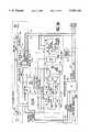
- FIG. 1is a block diagram showing a conventional television facility equipped with components for implementing the present invention.
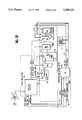
- FIG. 2is a block diagram showing one of the components according to the invention provided in the system of FIG. 1.
- FIG. 3Ais a block diagram of one unit of the component of FIG. 2.
- FIG. 3Bis a block diagram showing those portions of the unit of FIG. 3 for inserting icons into a video signal
- FIG. 3Cis a block diagram showing those portions of the unit of FIG. 3 for reading icons from a video signal
- FIG. 3Dis a block diagram showing those portions of the unit of FIG. 3 for identifying icons read from a video signal
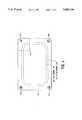
- FIG. 4is a pictorial view of a television picture screen, showing the location of identifying elements in accordance with the present invention.
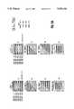
- FIGS. 5A and 5Bare pictorial views of portions of a variety of identifying patterns which can be employed in the practice of the present invention.
- FIGS. 6A, 6B and 6Care timing diagrams illustrating the operation of the device of FIG. 3.
- FIG. 1is a block diagram of a typical television distribution system which can be constructed in accordance with the present invention.
- the configuration of the exemplary systemhas been selected arbitrarily, simply for purposes of illustration. It is to be understood that any television program distribution system, regardless of its complexity and/or geographic extent, could serve as a basis for implementation of the invention.
- any television program distribution systemregardless of its complexity and/or geographic extent, could serve as a basis for implementation of the invention.
- the illustrated embodimentis described in connection with the N.T.S.C. standard, it should be appreciated that the present invention is applicable to all video formats, both those in present use as well as those formats which will be developed in the future.
- the system illustrated in FIG. 1includes television signal processing components, such as a satellite receiver 102, a video tape recorder 104 and a television signal processing and control area, known in the industry as a break studio, 106.
- Satellite receiver 102is connected to a receiving antenna 112 for receiving programs which are downloaded from a satellite and programs arriving at receiver 102 are conducted via a router 114 to other components of the system, such as the components 104 and 106.
- a program arriving via a downlink at receiver 102can be recorded by recorder 104 or immediately sent out over the air via control unit 106.
- a tape carrying a program which has previously been recordedcan be conducted from VTR 104 to control unit 106 via router 114.
- nodes 120are connected at each junction where television program signals enter, leave, or can be routed within, the station. As will be explained in greater detail below, each of these nodes 120 can be controlled to identify each television program, or transmission, which passes therethrough, and/or to insert identifying indicia into each such transmission.
- the system shown in FIG. 1is completed by units which are provided to utilize information provided in a video signal in accordance with the present invention, and which are coupled to nodes 120 by a cable 122.
- These additional unitsinclude a supervisory computer system composed of, for example, a unit 130 which maintains a schedule of the daily work to be performed at the station, a unit 132 which provides a log of programming which will be broadcast by the station, a unit 134 performing accounting functions, and one or more units 136 performing miscellaneous tasks requiring information provided in accordance with the present invention.
- the supervisory computer systemmay also store information identifying the desired broadcast time of a program and use that information in conjunction with information indicating the location, i.e. the tape recorder, where the program is stored to issue control signals which begin playback and route the recorded output to the station transmitter.
- the stationfurther includes an engineering network composed of a unit 140 which stores the identification of each program handled by the station, a unit 142 which stores data relating to the technical quality of the picture and sound content of programming received and sent, a unit 144 which may perform miscellaneous tasks, a unit 146 which constitutes a file server that maintains an updated record of relevant data relating to the programming received and broadcast by the station and a unit 148 which permits exchange of information between units 130-136, on the one hand, and units 140-146, on the other hand.
- an engineering networkcomposed of a unit 140 which stores the identification of each program handled by the station, a unit 142 which stores data relating to the technical quality of the picture and sound content of programming received and sent, a unit 144 which may perform miscellaneous tasks, a unit 146 which constitutes a file server that maintains an updated record of relevant data relating to the programming received and broadcast by the station and a unit 148 which permits exchange of information between units 130-136, on the one hand, and units 140-146, on
- programappearing in various legends in FIG. 1, and elsewhere herein, is employed to mean an identifiable television program element, i.e. a completed TV show or production, including commercials or public service announcements, which have been assembled for broadcast over the air or via a cable system.
- a programmay also be a live broadcast, such as of a news story or a sporting event.
- NABNational Association of Broadcasters
- FIG. 2is a block diagram showing one embodiment of a node 120 according to the present invention.
- the nodeincludes an interface 202 which connects the node to cable 122.
- Interface 202may be a local area network controller such as an interface marketed by Standard Microsystems Corp. under the model designation COM20020.
- Interface 202is connected via a control bus 204 and an address/data bus 206 to a CPU 210, a system memory 212 and a real time clock 214.
- CPU 210is connected via a master/slave control bus 220 to one or more modules 222, 224, 226 and 228.
- Module 222is constructed and controlled for inserting identifying indicia such as "icons" into a video signal or to read icons which have previously been inserted into the video signal.
- Module 222includes an analog portion and a digital portion which can derive digital signals representative of icons in a video signal processed in the analog portion. The time at which a set of icons passes a particular node can be read from clock 214 and stored with data identifying the program and the node which it passed.
- Module 224is a machine control module which can be configured to control the operation of a component of the television distribution system in response to information derived from the video signal by module 222.
- components which are adapted for machine controlinclude character generators, routers and video tape recorders such as the Ampex VPR-2B and the Ampex VPR-250 and other addressable components.
- Module 226is a digital audio icon interface which can modify the audio portion of a television program in response to information which has been added to the video signal thereof and decoded in module 222.
- Module 228is a station time reader which receives an input representing the current time and associates a time indication, or stamp, with each set of data obtained from module 222.
- Machine control 224 and interface 226are optional components which can be provided when desired. Certain of the capabilities which will be created by provision of such components will be described below, after the device and procedure for inserting information into a video signal and reading such information have been described.
- FIG. 3is a schematic block diagram of the icon encode/decode module 222.
- FIGS. 3.1-3.3depict various portions of the module 222 in accordance with the function performed.
- FIGS. 6.1-6.3are timing diagrams showing the waveforms of signals at certain points in the circuits of FIGS. 3.1-3.3, respectively. The locations in the circuits of FIGS. 3.1-3.3 where the signals of FIGS. 6.1-6.3 appear are indicated by letters corresponding to those identifying the corresponding waveforms of FIGS. 6.1-6.3.
- FIG. 3.1there is illustrated one preferred embodiment of the portion of module 222 which interacts with a video signal in order to insert information into the signal.
- the circuit shown in FIG. 3.1includes a video buffer 302 and a key amplifier 304 which are connected together in series in the associated television signal path.
- the video signal applied to the input of amplifier 302, waveforms a and a' in FIG. 6.1,is conducted without modification to a first signal input of amplifier 304.
- Key Amplifier 304is a conventional element used in television signal processing systems. It is basically a high speed video switch that passes, in this case, either the unmodified input video or video in which identifying information has been inserted after a D/A conversion process.
- this identifying informationis preferably in the form of graphic symbols or "icons” as explained below.
- Selection of the input signal to amplifier 304is controlled by the signal "Insert" waveform s of FIG. 6 1 , which is generated by a sync stripper/clock generator circuit 306.
- the video signal leaving buffer amplifier 302is conducted to the sync stripper/clock generator 306 which has a basic timing element.
- the circuit 306includes a type LM1881 video sync separator chip marketed by National Semiconductor, the output of which (designated INSERT) is connected to a subsidiary clock generator 310 as well as the key amplifier 304.
- the amplifier 304has a second video input which receives one or more icons which can be added to the video signal.
- the icon datais provided to the second video input of amplifier 304 by circuitry which includes a FIFO memory 320 and a digital/analog converter 322. Signals representing the desired icon patterns are read from memory 320, are converted to analog form in converter 322 and are added to the video signal at the appropriate points in time.
- Devices 306 and 320are controlled by a microprocessor 330 which has an associated memory 332.
- Microprocessor 330is connected to clock generator 306 via a control bus 340.
- Microprocessor 330is connected to memory 332 and memory 320 via a data bus 342 and an address bus 344.
- a signal up -- insert -- enable(waveform r in FIG. 6.1) is generated in device 306 and supplied to microprocessor 330 via control bus 340. This signal alerts the microprocessor to load FIFO memory 320 with appropriate icon patterns stored in the microprocessor's associated memory 332. Microprocessor 330 does not have to load memory 320 with all icons to be stored into a frame at one time since the FIFO memory 320 can be read from and written to at the same time. In the illustrated embodiment, the data for only the first line of icons to be inserted into the frame is loaded into the FIFO memory at a time.
- the clock generator 306under the control of the microprocessor 330, activates the timing signal INSERT which causes the clock generator 310 to issue a series of rapid clock pulses to the FIFO memory 320 and the D/A converter 322.
- the FIFO memory 320in response to these clock pulses, outputs the previously stored icon information, a pixel at a time, which is converted to analog form by the converter 322 and is then inserted into the video signal by the key amplifier 304.
- information identifying a programmay be added to the video signal of the program.
- the informationis in the form of signal components which will appear at selected locations in the resulting television picture as icons, or graphic symbols. These icons can appear in a variety of patterns; each pattern represents a specific information unit, or datum; and a succession of these patterns provides the desired information.
- a first set of pixelsis inserted in successive lines of Field 1 of the frame as shown for example in FIG. 5.1.
- a second set of pixelsis inserted in associated successive lines of Field 2 of the same frame.
- the video signals in the preselected areas reserved for iconsare converted into digital pixel signals and are then stored in memory 314 of FIG. 3.2 at locations such that all pixels of Fields 1 and 2 for a given icon can be read out together in a selected order.
- FIG. 4shows an example of four such icon areas 404a-404d of a video frame. It is recognized that the icons may be placed in other areas of the frame.
- the vertical positions and extents of icon areas 404are determined by counting the horizontal sync pulses from the start of each field and producing vertical gate pulses in response to selected horizontal sync pulses.
- two iconsare inserted into lines 22-27 and two are inserted into lines 257-262 of each frame for a total of four icons per frame, as shown in FIG. 4. Since each frame has two interleaved fields, each icon has a vertical height of 12 lines as shown in FIG. 5.1. It should be appreciated of course that various numbers of icons can be inserted into a particular frame. For example, three icons can be stacked in the same horizontal position in each corner of the frame for a total of 12 icons per frame.
- the horizontal positions and extents of icon areas 404are determined by producing a train of pixel clock pulses which divide each scan line into a plurality of pixel locations, counting these pixel clock pulses and producing horizontal gate pulses in response to selected pixel clock pulses.
- the coincidence of vertical and horizontal gate pulsescorrespond to an icon area.
- FIG. 6.2contains timing diagrams showing the waveforms of signals at certain points in the circuit of FIG. 3.2.
- waveforms a and a'show two successive parts of one field of a color television signal which starts with a vertical blanking interval, to the left of waveform a of FIG. 6.2 during which equalizing pulses and sync pulses are provided, followed by eleven picture lines (picture lines 10-20) which will not appear on the television screen.
- the vertical blanking intervalis followed by an active video period composed of 2421/2 picture lines.
- each picture lineincludes a horizontal sync pulse 610, a color burst 612 and a picture information region 614.
- the region 614 containing picture informationis depicted as a pulse in picture line 21 but is not depicted for the other picture lines.
- FIG. 6.2shows, at waveform g, the field identification pulse, odd -- even, extracted from each field signal by device 306 of FIG. 3.2.
- the odd -- even signalis conducted to the reset input RST of a counter 309, the output of which is a ten bit parallel digital signal that represents the pixel address within the frame.
- the counter 309resets and generates sequential ten bit pixel addresses when the field changes from odd to even and vice versa.
- the pixel frame addresses of each icon pixelwill not be contiguous from line to line. Consequently, the ten bit pixel address generated by the counter 309 is conducted to a PROM device 312 which re-maps the pixel frame address to contiguous memory addresses of the memory 314.
- the pixels of each read icon entering memory 314is stored into contiguous memory locations.
- waveform brepresents horizontal sync pulses, separated h -- sync, extracted from the video signal of waveforms a and a'.
- This signalis generated within device 306 of FIG. 3.2.
- a signal line -- gateas shown in waveform c of FIG. 6.2, is produced which provides a first gate pulse synchronized with picture lines 22-27 at the top of the picture frame and a second gate pulse synchronized with picture lines 257-262 at the bottom of the picture frame.
- This signalis also produced in device 306 of FIG. 3.2.
- each gate pulse line -- gatethe generator 306 produces a series of pulses identified as pixel -- gate pulses, which are shown in waveform d of FIG. 6.2.
- Each pixel -- gate pulsecoincides with one horizontal row of a respective icon area.
- the frames of the illustrated embodimenthave four icon areas, one icon area at each corner of the frame. Because each picture line passing through an icon area passes through two icon areas in the illustrated embodiment, alternate ones of these pixel -- gate pulses coincide with a defined part of the beginning and end, respectively, of each picture line.
- Each of these gate pulsesis used to gate two series of gated -- pixel -- clocks generated by the generator 306, which are shown in waveforms e and f of FIGS. 6.2.
- the gated -- pixel -- clocks e(phase 1) clock an A/D converter 308 so that only that portion of the video signal corresponding to a preselected icon area is converted into digital pixel data.
- the gated -- pixel -- clocks f(phase 2) clock the counter 309 which generates the pixel frame addresses described above which are mapped by the PROM 312 to contiguous memory addresses.
- Each pixel written into memory 314is constituted by an eight-bit word written into memory 314 in parallel.
- iconsare identified by comparing icon pixel data stored in addressable digital memory 314 during a previous icon read operation with icon pixel data stored in a pattern RAM 318.
- the pixel data read from the picture frame and stored in memory 314are outputted to a shift register 315 which delivers the pixel data a bit at a time to a pattern recognition unit.
- the pattern recognition unitis implemented with a fuzzy pattern comparator 316 and pattern RAM 318.
- comparator 316is a device marketed by American NeuraLogix, Inc., of Sanford, Fla., under model designation NLX 110. This device has eight pattern data inputs, so that RAM 318 may be provided with eight data outputs for simultaneously supplying up to eight selected patterns to comparator 316.
- the NLX110 integrated circuitallows for simultaneous comparison of up to eight known patterns with one unknown pattern.
- the illustrated embodiment of the present inventionutilizes eight different icon patterns.
- One icon patternis designated as a reference icon pattern and is located in the upper left hand corner of the active picture window, as indicated at 404a in FIG. 4. This reference icon pattern is used by control microprocessor 330 to set the error threshold of the NLX110 pattern comparator 316 for the next three icons, present in areas 404b, c and d, thereby tracking out noise or distortion on the incoming icons.
- the other seven selected icon patternsconstitute an icon primitive set.
- N7
- R3
- the first 128 permutationscan be assigned to correspond to the seven bit ASCII code for plain text transmission.
- the remaining valuescan be assigned to special purposes.
- the types of icon patterns employed in the illustrated embodiment of the present inventionhave characteristics which enable them to be identified, or decoded, by a fuzzy logic comparator with a high degree of reliability even when the video signal contains noise or distortion or when an error in the timing of the video signal prevents one or two rows or columns of icon pixels from reaching comparator 316.
- these icon pattern characteristicsinclude the following: there are only eight different icon patterns to be recognized, while each pattern is composed of 144 pixels; each pattern consists of pixels having only two or three different values spaced relatively far apart on the gray scale; each pattern has no more than four changes in gray level value in both the horizontal and vertical directions; and, with the exception of two corners of each triangle pattern, a given gray level value is present at at least two successive pixel locations in both the horizontal and vertical directions. Therefore, the eight different patterns can be made to represent relatively simple geometric shapes which differ sufficiently from one another to permit reliable identification of each pattern with comparator 316 set to a relatively low recognition threshold.
- the icon information stored for a particular frameis identified, or decoded, within a period equal to 12 picture lines with 18.2 MHz shift clocks.
- waveform gis the signal odd -- even produced in device 306 to identify the current field of each frame. The state of this signal is inverted by the leading edge of each v -- sync pulse (FIG. 6.1).
- device 306At each positive transition of the signal odd -- even, corresponding to the vertical blanking interval at the start of each odd field, device 306 generates a pulse compare -- enable having a period of 12 picture lines, as represented by waveform h.
- each pulse compare -- enabledevice 306 generates a train of four spaced pulses read winner, represented by waveform i, and four spaced pulses compare -- gate, represented by waveform j. Each pulse compare -- gate immediately precedes an associated pulse read -- winner.
- device 306generates a train of 144 pulses of gated -- clocks, shown in generalized form as waveform k. As shown by waveforms l and m, each pulse of gated -- clocks is composed of two trains of eight clock pulses, each at a pulse rate of 18.2 MHz.
- device 306generates a pulse mem -- read, shown by waveform m, for each pulse of gated -- clocks.
- Counter 319, FIG. 3.3is reset by the odd -- even pulse, waveform g, at the start of every frame. Mem -- read is supplied to the input of counter 319 which provides a ten bit pixel read address for memory 314 via mux 311, FIG. 3.3.
- One of the trains of eight clock pulsesis supplied to shift register 315 to shift pixel bits serially into comparator 316 and the other train, identified as waveform m (phase 2), is supplied to comparator 316 to trigger a comparison operation.
- Each pulse of phase 1shifts a single pixel bit and each pulse of phase 2 triggers a comparison with respect to the previously shifted bit.
- the bits of phase 2are shifted in phase by 180° from the bits of phase 1.
- Each bit arriving from shift register 315is compared with an associated bit of each of the eight patterns supplied by RAM 318.
- a corresponding read -- winner pulseis delivered to microprocessor 330, and in response to that pulse, microprocessor 330 reads the comparison result out of comparator 316.
- This comparison resultis in the form of a signal identifying the reference pattern which most closely matches the pattern represented by the bits delivered from register 315. This signal is supplied to memory 332 along with identification of the associated icon location in the active picture window.
- compare -- enablegenerates, in microprocessor 330, a done signal indicating that all four icons of a frame have been individually identified as to pattern and location.
- the information, i.e. the character, which they representcan be identified, for example, by means of a look-up table in memory 332.
- a node in accordance with one aspect of the inventionis disposed at the input side of the transmitter to read the identifying information stored in the television signal so as to provide the central data processing system of the facility with a contemporaneous and reliable indication that broadcast of the identified program has begun. This information will be stored together with an indication of the time that transmission began.
- the stored informationmay be deleted from the television signal prior to transmission.
- the identifying informationi.e. the icons, may remain in the television signal at the time it is broadcast or transmitted for use in order to determine viewing patterns at individual television receivers, for example in order to derive program viewership.
- each television receiver which is to be monitoredwould be equipped with a decoder containing appropriate portions of the node of FIG. 2 connected to the output of the receiver tuner or forming part of an external tuner. Identification data contained in each program to which the receiver is tuned could then be stored together with a time indication or could be transmitted, possibly immediately, via a telephone line to a control data collection point. As a consequence, program viewing ratings can be determined on a virtually instantaneous basis.
- identification data according to the inventionWhen the identification data according to the invention is used to determine viewing patterns, it may be desirable to transmit such data at fixed intervals of, for example, five minutes during each program, as well as at the start of each commercial, and after each commercial, in order to monitor patterns of channel switching in the middle of programs.
- Such a technique for monitoring viewing patternswould eliminate ratings errors that result from incorrect reporting by viewers of the programs which they watched.
- FIG. 4shows an active picture window having an outer border, or boundary, 402 delimiting the area of a video image formed by all picture information contained in a video signal, i.e. all portions of the video signal other than the horizontal and vertical blanking portions.
- an outer border, or boundary, 406Within the active picture window there is a safe action area enclosed by an outer border, or boundary, 406, and within the safe action area there is a safe title area enclosed by an outer border, or boundary, 408.
- the safe action areawill contain that part of the picture which it is desired to present to the viewer, i.e. all significant action in a television program, and the safe title area will contain all of the more important information, such as titles, to ensure that this information will be visible on the majority of home television receivers.
- FIG. 4further shows four small rectangular icon areas 404 located at the four corners of the active picture window, outside of the safe action area enclosed by border 406.
- icon areas 404are confined to corner regions each delimited by horizontal and vertical radial lines 410 originating at the center of curvature of the respective corners. These regions provide adequate space for the icons while assuring that they will not be seen by home viewers.
- icon areas 404can be located wholly or partly within border 406, but preferably outside of border 408. In this case, icons in areas 404 will create no more than minimal viewer distractions, particularly since, as will be described below, icons will normally be present in a program element for only a period of several seconds.
- icon areas 404are located in the active picture window, they can be visually observed by personnel at a television station and, if played from tape in sufficiently slow motion, can be visually interpreted.
- One icon area 404amay be reserved for a reference icon which may have a special shape and which is present in each television picture frame that contains identifying information.
- the information contained in the framecan be represented by the presence or absence of icons at the other three locations and/or by the shape of the icon or icons at one or more of the other three locations.
- FIG. 4A simple example of an icon scheme according to the invention is shown in FIG. 4, where all of the icons have a square or rectangular outline. Such outlines can be produced in a relatively easy manner by gating circuitry as described above.
- the reference icon area 404ais located at the upper left corner and has the form in the illustrated embodiment of a hollow black rectangle enclosing a hollow gray rectangle, with a white square at the center.
- the other three icons 404b-dare divided diagonally into a black triangle and a white triangle; to facilitate differentiation, the black triangles of icons in areas 404b and c point down and to the right; that of the icon in area 404d points up and to the left.
- FIGS. 5.1-5.2show a number of possible icon patterns which may be used in the practice of the present invention.
- Icon field patterns 5a-5h of FIGS. 5.1-5.2show the icon pixels present in Field 1 of a television picture frame for eight unique icons
- icon field patterns 5i-5pshow the corresponding icon pixels present in Field 2 of the same picture frame for the same eight icons.
- the lines of the associated icon field patternsare interlaced to depict a complete icon pattern.
- the field patterns 5a and 5iare combined to form the reference icon pattern in area 404a of FIG. 4, while the icon field patterns 5b and 5j form the icon pattern in area 404d of FIG.
- Icon field patterns 5d and 5l, 5e and 5m, 5f and 5n, 5g and 5o, and 5h and 5pmay be respectively combined to form five other icon patterns which may be employed.
- white pixelsare depicted without hatching, gray pixels with wide hatching and black pixels with close hatching.
- each iconcomprises a plurality of pixels having different gray levels or other colors.
- each icon patternis relatively simple and has a relatively large number of pixels so as to provide a high degree of redundancy and imperviousness to signal degradation.
- Program information provided according to the present inventioncan be put to a variety of beneficial uses.
- the information provided by icons according to the inventioncan be employed to assist analysis of edited program material.
- the source of the original materiali.e. the tape on which the original video information is stored, is sometimes difficult to determine.
- Re-editing of such a programwould be facilitated by using icons to label every frame on a given reel of tape with a unique symbol or set of symbols.
- an icon decoderan accurate shot list can be assembled.
- Machine readable commercial position informationis also readily provided.
- live broadcastssuch as sporting events
- commercialsare not transmitted at specific times, but float within the body of the program. Icons can be inserted at the originating point of the program to arm, or trigger, automatic commercial insertion equipment at every station which carries the program. In this manner, all local affiliates of a network or cable originator would remain in sync with the live programming.
- Iconscan be employed to embed identification into programs and/or commercials. By embedding icons in finished programs or commercials, they can be monitored by off air receivers to make a log of actual vs. intended program material broadcast. In addition, bills to advertisers can be automatically generated.
- Selected icon patternscould be reserved to serve as smart test signals, or test signal identification patterns which would allow measurement equipment in television facilities to automatically make appropriate measurements on test signals as they pass through the measurement device.
- the information derived in this mannercan be relayed to a node and then to the station control computer for use to control various processes in the station and to generate task lists and a database.
- iconscan be employed as reel and take identifiers.
- the icon encoding circuitry described abovecan be adapted to operate in conjunction with portable video tape recorders either as stand alone equipment or as part of a video camera.
- a portable data entry devicesuch as a hand held computer
- a directorcan enter reel, scene and take numbers into the video taping equipment just prior to shooting the scene.
- This informationwould go to an embedded icon encoder within the video recorder or camera so that all recorded frames would be labeled with the appropriate information.
- This informationwould be of great value in post production of the finished program and would constitute a machine readable equivalent of the clapboard and slate which are presently used.
- Iconscan be employed to provide cross country routing information. Special instructions can be encoded in the icon format in accordance with the present invention, in the leader information of a program or commercial. This information would then be usable in real time by automatic switching equipment located in different parts of the country to route the signal to its destination without it being necessary for personnel at the various switching points to have prior knowledge of the specific route.
Landscapes
- Engineering & Computer Science (AREA)
- Signal Processing (AREA)
- Multimedia (AREA)
- Health & Medical Sciences (AREA)
- Biomedical Technology (AREA)
- General Health & Medical Sciences (AREA)
- Television Systems (AREA)
- Television Signal Processing For Recording (AREA)
- Two-Way Televisions, Distribution Of Moving Picture Or The Like (AREA)
Abstract
Description
Claims (12)
Priority Applications (15)
| Application Number | Priority Date | Filing Date | Title |
|---|---|---|---|
| US08/003,481US5450134A (en) | 1993-01-12 | 1993-01-12 | Video facility management system for encoding and decoding video signals to facilitate identification of the video signals |
| CA002157483ACA2157483C (en) | 1993-01-12 | 1994-01-06 | Video facility management system_for encoding and decoding video signals to facilitate identification of the video signals |
| AU59650/94AAU5965094A (en) | 1993-01-12 | 1994-01-06 | Video facility management system |
| CN94190933ACN1051194C (en) | 1993-01-12 | 1994-01-06 | Apparatus for tracking television program delivery and method of use thereof |
| JP6516213AJPH08505500A (en) | 1993-01-12 | 1994-01-06 | Television facility management device |
| CNB991193067ACN1169363C (en) | 1993-01-12 | 1994-01-06 | Apparatus for tracing transmission condition of TV performance and method used thereof |
| DE69430299TDE69430299T2 (en) | 1993-01-12 | 1994-01-06 | CONTROL SYSTEM FOR A VIDEO SETUP |
| BR9405655ABR9405655A (en) | 1993-01-12 | 1994-01-06 | Video installation management system |
| ES94905598TES2174869T3 (en) | 1993-01-12 | 1994-01-06 | VIDEO FACILITIES MANAGEMENT SYSTEM. |
| PCT/US1994/000206WO1994016525A1 (en) | 1993-01-12 | 1994-01-06 | Video facility management system |
| KR1019950702872AKR100309023B1 (en) | 1993-01-12 | 1994-01-06 | Television program flow track device and method |
| EP94905598AEP0679315B1 (en) | 1993-01-12 | 1994-01-06 | Video facility management system |
| US08/388,422US5557334A (en) | 1993-01-12 | 1995-02-14 | Apparatus for tracking the flow of video signals by incorporating patterns of machine readable signals which will appear at predetermined locations of a television picture |
| US09/154,389USRE37991E1 (en) | 1993-01-12 | 1998-09-16 | Apparatus for tracking the flow of video signals by incorportating patterns of machine readable signals which will appear at predetermined locations of a television picture |
| CN99119305ACN1258994A (en) | 1993-01-12 | 1999-09-08 | Equipment for tracking television programme transmission situation and its using method |
Applications Claiming Priority (1)
| Application Number | Priority Date | Filing Date | Title |
|---|---|---|---|
| US08/003,481US5450134A (en) | 1993-01-12 | 1993-01-12 | Video facility management system for encoding and decoding video signals to facilitate identification of the video signals |
Related Child Applications (1)
| Application Number | Title | Priority Date | Filing Date |
|---|---|---|---|
| US08/388,422Continuation-In-PartUS5557334A (en) | 1993-01-12 | 1995-02-14 | Apparatus for tracking the flow of video signals by incorporating patterns of machine readable signals which will appear at predetermined locations of a television picture |
Publications (1)
| Publication Number | Publication Date |
|---|---|
| US5450134Atrue US5450134A (en) | 1995-09-12 |
Family
ID=21706072
Family Applications (1)
| Application Number | Title | Priority Date | Filing Date |
|---|---|---|---|
| US08/003,481Expired - LifetimeUS5450134A (en) | 1993-01-12 | 1993-01-12 | Video facility management system for encoding and decoding video signals to facilitate identification of the video signals |
Country Status (11)
| Country | Link |
|---|---|
| US (1) | US5450134A (en) |
| EP (1) | EP0679315B1 (en) |
| JP (1) | JPH08505500A (en) |
| KR (1) | KR100309023B1 (en) |
| CN (3) | CN1169363C (en) |
| AU (1) | AU5965094A (en) |
| BR (1) | BR9405655A (en) |
| CA (1) | CA2157483C (en) |
| DE (1) | DE69430299T2 (en) |
| ES (1) | ES2174869T3 (en) |
| WO (1) | WO1994016525A1 (en) |
Cited By (104)
| Publication number | Priority date | Publication date | Assignee | Title |
|---|---|---|---|---|
| US5602580A (en)* | 1993-09-17 | 1997-02-11 | Tseng; Ling-Yuan | Video communication controller using FM sideband transmission |
| US5652626A (en)* | 1993-09-03 | 1997-07-29 | Kabushiki Kaisha Toshiba | Image processing apparatus using pattern generating circuits to process a color image |
| US5760838A (en)* | 1994-09-30 | 1998-06-02 | Intel Corporation | Method and system for configuring a display |
| EP0789497A3 (en)* | 1996-02-12 | 1998-07-08 | Tektronix, Inc. | Progammable instrument for automatic measurement of compressed video quality |
| US5826165A (en)* | 1997-01-21 | 1998-10-20 | Hughes Electronics Corporation | Advertisement reconciliation system |
| EP0888019A1 (en)* | 1997-06-23 | 1998-12-30 | Hewlett-Packard Company | Method and apparatus for measuring the quality of a video transmission |
| WO1998026529A3 (en)* | 1996-12-11 | 1999-01-07 | Nielsen Media Res Inc | Interactive service device metering systems |
| US5929942A (en)* | 1997-04-04 | 1999-07-27 | Avid Technology, Inc. | Computer system and computer implemented process for editing video fields |
| US5987150A (en)* | 1996-08-30 | 1999-11-16 | Intel Corporation | Video capturing using on-screen graphics |
| US6091407A (en)* | 1996-10-07 | 2000-07-18 | Sony Corporation | Method and apparatus for manifesting representations of scheduled elements in a broadcast environment |
| US6128001A (en)* | 1997-04-04 | 2000-10-03 | Avid Technology, Inc. | Methods and apparatus for changing a color of an image |
| US6141693A (en)* | 1996-06-03 | 2000-10-31 | Webtv Networks, Inc. | Method and apparatus for extracting digital data from a video stream and using the digital data to configure the video stream for display on a television set |
| US6173271B1 (en)* | 1997-11-26 | 2001-01-09 | California Institute Of Technology | Television advertising automated billing system |
| US6269195B1 (en) | 1997-04-04 | 2001-07-31 | Avid Technology, Inc. | Apparatus and methods for selectively feathering a composite image |
| US6292216B1 (en)* | 1998-04-14 | 2001-09-18 | Sony Corporation | Control signal generating circuit |
| US6327619B1 (en) | 1998-07-08 | 2001-12-04 | Nielsen Media Research, Inc. | Metering of internet content using a control |
| US6330033B1 (en) | 1995-12-07 | 2001-12-11 | James Carl Cooper | Pulse detector for ascertaining the processing delay of a signal |
| US6351557B1 (en) | 1998-04-03 | 2002-02-26 | Avid Technology, Inc. | Method and apparatus for color manipulation |
| US6392710B1 (en) | 1998-04-03 | 2002-05-21 | Avid Technology, Inc. | Graphical user interface for field-based definition of special effects in a video editing system |
| US6417891B1 (en) | 1999-04-16 | 2002-07-09 | Avid Technology, Inc. | Color modification on a digital nonlinear editing system |
| US6460079B1 (en) | 1999-03-04 | 2002-10-01 | Nielsen Media Research, Inc. | Method and system for the discovery of cookies and other client information |
| US6477271B1 (en) | 2000-04-07 | 2002-11-05 | Avid Technology, Inc. | Secondary color modification of a digital image |
| US20030014363A1 (en)* | 2001-06-25 | 2003-01-16 | Vincent Sethi | Electronic vouchers and a system and method for issuing the same |
| WO2003009591A1 (en)* | 2001-07-16 | 2003-01-30 | See-Rt Ltd. | Methods for data transmission |
| USRE37991E1 (en)* | 1993-01-12 | 2003-02-18 | Visual Automation Systems, Inc. | Apparatus for tracking the flow of video signals by incorportating patterns of machine readable signals which will appear at predetermined locations of a television picture |
| US20030055722A1 (en)* | 2001-09-19 | 2003-03-20 | Jagtec, Inc. | Method and apparatus for control of advertisements |
| US20030070174A1 (en)* | 2001-10-09 | 2003-04-10 | Merrill Solomon | Wireless video-on-demand system |
| US20030071824A1 (en)* | 1999-04-16 | 2003-04-17 | Robert Gonsalves | Multi-tone representation of a digital image on a digital nonlinear editing system |
| US6556247B1 (en)* | 1999-12-30 | 2003-04-29 | Microsoft Corporation | Method and system for decoding data in the horizontal overscan portion of a video signal |
| US6571255B1 (en) | 1999-04-16 | 2003-05-27 | Robert Gonsalves | Modification of media with common attributes on a digital nonlinear editing system |
| US6597405B1 (en)* | 1996-11-01 | 2003-07-22 | Jerry Iggulden | Method and apparatus for automatically identifying and selectively altering segments of a television broadcast signal in real-time |
| US6674481B1 (en)* | 1997-10-20 | 2004-01-06 | Sony Corporation | Display apparatus, marker signal making process, marker signal detector circuit, and control signal generator circuit |
| US20040044961A1 (en)* | 2002-08-28 | 2004-03-04 | Leonid Pesenson | Method and system for transformation of an extensible markup language document |
| US6704058B2 (en) | 1999-12-30 | 2004-03-09 | Microsoft Corporation | System and method of adaptive timing estimation for horizontal overscan data |
| US6735776B1 (en) | 1999-02-01 | 2004-05-11 | Kim R. Legate | Motion picture editing and distribution |
| US6742188B1 (en) | 1997-02-04 | 2004-05-25 | Microsoft Corporation | Method and system for encoding data in the horizontal overscan portion of a video signal |
| US20040240729A1 (en)* | 2000-04-07 | 2004-12-02 | Cooper Brian C. | Secondary color modification of a digital image |
| US20050015795A1 (en)* | 1996-11-01 | 2005-01-20 | Jerry Iggulden | Method and apparatus for selectively altering a televised video signal in real-time |
| US6847373B1 (en) | 1999-04-16 | 2005-01-25 | Avid Technology, Inc. | Natural color matching in a video editing system |
| US6867789B1 (en) | 2000-02-15 | 2005-03-15 | Bank One, Delaware, National Association | System and method for generating graphical user interfaces |
| US20050137902A1 (en)* | 2003-12-22 | 2005-06-23 | Simon Bowie-Britton | Methods and systems for managing successful completion of a network of processes |
| US6937289B1 (en) | 1999-12-30 | 2005-08-30 | Microsoft Corporation | Method and system for downloading and storing interactive device content using the horizontal overscan portion of a video signal |
| US20050216581A1 (en)* | 1998-06-23 | 2005-09-29 | Blumenau Trevor I | Use of browser history file to determine web site reach |
| US7058817B1 (en) | 1999-07-02 | 2006-06-06 | The Chase Manhattan Bank | System and method for single sign on process for websites with multiple applications and services |
| US7143174B2 (en) | 2002-06-12 | 2006-11-28 | The Jpmorgan Chase Bank, N.A. | Method and system for delayed cookie transmission in a client-server architecture |
| US7150028B1 (en) | 1999-12-30 | 2006-12-12 | Microsoft Corporation | Method and system for downloading, storing and displaying coupon data using the horizontal overscan portion of a video signal |
| US7203663B1 (en) | 2000-02-15 | 2007-04-10 | Jpmorgan Chase Bank, N.A. | System and method for converting information on paper forms to electronic data |
| US7246263B2 (en) | 2000-09-20 | 2007-07-17 | Jpmorgan Chase Bank | System and method for portal infrastructure tracking |
| US7246324B2 (en) | 2002-05-23 | 2007-07-17 | Jpmorgan Chase Bank | Method and system for data capture with hidden applets |
| US7266839B2 (en) | 2001-07-12 | 2007-09-04 | J P Morgan Chase Bank | System and method for providing discriminated content to network users |
| US7321864B1 (en) | 1999-11-04 | 2008-01-22 | Jpmorgan Chase Bank, N.A. | System and method for providing funding approval associated with a project based on a document collection |
| US7353383B2 (en) | 2002-03-18 | 2008-04-01 | Jpmorgan Chase Bank, N.A. | System and method for single session sign-on with cryptography |
| US7376838B2 (en) | 2003-07-17 | 2008-05-20 | Jp Morgan Chase Bank | Method for controlled and audited access to privileged accounts on computer systems |
| US7392386B2 (en) | 2004-01-28 | 2008-06-24 | J P Morgan Chase Bank | Setuid-filter method for providing secure access to a credentials store for computer systems |
| US20080166057A1 (en)* | 2004-12-24 | 2008-07-10 | Nec Corporation | Video Structuring Device and Method |
| US7426530B1 (en) | 2000-06-12 | 2008-09-16 | Jpmorgan Chase Bank, N.A. | System and method for providing customers with seamless entry to a remote server |
| US7472171B2 (en) | 2002-06-21 | 2008-12-30 | Jpmorgan Chase Bank, National Association | Method and system for determining receipt of a delayed cookie in a client-server architecture |
| US7593876B2 (en) | 2003-10-15 | 2009-09-22 | Jp Morgan Chase Bank | System and method for processing partially unstructured data |
| US20090251600A1 (en)* | 1995-12-07 | 2009-10-08 | Cooper J Carl | AV Timing Measurement for MPEG Type Television |
| US7685013B2 (en) | 1999-11-04 | 2010-03-23 | Jpmorgan Chase Bank | System and method for automatic financial project management |
| US7689504B2 (en) | 2001-11-01 | 2010-03-30 | Jpmorgan Chase Bank, N.A. | System and method for establishing or modifying an account with user selectable terms |
| US7747866B1 (en) | 2000-08-24 | 2010-06-29 | Jpmorgan Chase Bank, N.A. | System and method providing improved error detection related to transmission of data over a communication link |
| US7756816B2 (en) | 2002-10-02 | 2010-07-13 | Jpmorgan Chase Bank, N.A. | System and method for network-based project management |
| US7783578B2 (en) | 2001-09-21 | 2010-08-24 | Jpmorgan Chase Bank, N.A. | System for providing cardless payment |
| US7792068B2 (en) | 1998-04-03 | 2010-09-07 | Robert Iii Roswell | Satellite receiver/router, system, and method of use |
| US20100332399A1 (en)* | 2009-06-29 | 2010-12-30 | Glenn Benson | System and method for partner key management |
| US7941533B2 (en) | 2002-02-19 | 2011-05-10 | Jpmorgan Chase Bank, N.A. | System and method for single sign-on session management without central server |
| US7987501B2 (en) | 2001-12-04 | 2011-07-26 | Jpmorgan Chase Bank, N.A. | System and method for single session sign-on |
| US8160960B1 (en) | 2001-06-07 | 2012-04-17 | Jpmorgan Chase Bank, N.A. | System and method for rapid updating of credit information |
| US8185877B1 (en) | 2005-06-22 | 2012-05-22 | Jpmorgan Chase Bank, N.A. | System and method for testing applications |
| US8190893B2 (en) | 2003-10-27 | 2012-05-29 | Jp Morgan Chase Bank | Portable security transaction protocol |
| US8284774B2 (en)* | 1998-04-03 | 2012-10-09 | Megawave Audio Llc | Ethernet digital storage (EDS) card and satellite transmission system |
| US8301493B2 (en) | 2002-11-05 | 2012-10-30 | Jpmorgan Chase Bank, N.A. | System and method for providing incentives to consumers to share information |
| US8321682B1 (en) | 2008-01-24 | 2012-11-27 | Jpmorgan Chase Bank, N.A. | System and method for generating and managing administrator passwords |
| US8335855B2 (en) | 2001-09-19 | 2012-12-18 | Jpmorgan Chase Bank, N.A. | System and method for portal infrastructure tracking |
| US8473735B1 (en) | 2007-05-17 | 2013-06-25 | Jpmorgan Chase | Systems and methods for managing digital certificates |
| US8571975B1 (en) | 1999-11-24 | 2013-10-29 | Jpmorgan Chase Bank, N.A. | System and method for sending money via E-mail over the internet |
| US8583926B1 (en) | 2005-09-19 | 2013-11-12 | Jpmorgan Chase Bank, N.A. | System and method for anti-phishing authentication |
| US8713168B2 (en) | 2010-09-22 | 2014-04-29 | The Nielsen Company (Us), Llc | Methods and apparatus to determine impressions using distributed demographic information |
| US8793490B1 (en) | 2006-07-14 | 2014-07-29 | Jpmorgan Chase Bank, N.A. | Systems and methods for multifactor authentication |
| US8849716B1 (en) | 2001-04-20 | 2014-09-30 | Jpmorgan Chase Bank, N.A. | System and method for preventing identity theft or misuse by restricting access |
| US8930701B2 (en) | 2012-08-30 | 2015-01-06 | The Nielsen Company (Us), Llc | Methods and apparatus to collect distributed user information for media impressions and search terms |
| US8954536B2 (en) | 2010-12-20 | 2015-02-10 | The Nielsen Company (Us), Llc | Methods and apparatus to determine media impressions using distributed demographic information |
| US9015255B2 (en) | 2012-02-14 | 2015-04-21 | The Nielsen Company (Us), Llc | Methods and apparatus to identify session users with cookie information |
| US9100132B2 (en) | 2002-07-26 | 2015-08-04 | The Nielsen Company (Us), Llc | Systems and methods for gathering audience measurement data |
| US9118542B2 (en) | 2011-03-18 | 2015-08-25 | The Nielsen Company (Us), Llc | Methods and apparatus to determine an adjustment factor for media impressions |
| US9124769B2 (en) | 2008-10-31 | 2015-09-01 | The Nielsen Company (Us), Llc | Methods and apparatus to verify presentation of media content |
| US9209917B2 (en) | 2005-09-26 | 2015-12-08 | The Nielsen Company (Us), Llc | Methods and apparatus for metering computer-based media presentation |
| US9332035B2 (en) | 2013-10-10 | 2016-05-03 | The Nielsen Company (Us), Llc | Methods and apparatus to measure exposure to streaming media |
| US9355138B2 (en) | 2010-06-30 | 2016-05-31 | The Nielsen Company (Us), Llc | Methods and apparatus to obtain anonymous audience measurement data from network server data for particular demographic and usage profiles |
| US9386111B2 (en) | 2011-12-16 | 2016-07-05 | The Nielsen Company (Us), Llc | Monitoring media exposure using wireless communications |
| US9419957B1 (en) | 2013-03-15 | 2016-08-16 | Jpmorgan Chase Bank, N.A. | Confidence-based authentication |
| US9641336B2 (en) | 2013-12-31 | 2017-05-02 | The Nielsen Company (Us), Llc | Methods and apparatus to collect distributed user information for media impressions and search terms |
| US10068246B2 (en) | 2013-07-12 | 2018-09-04 | The Nielsen Company (Us), Llc | Methods and apparatus to collect distributed user information for media impressions |
| US10148726B1 (en) | 2014-01-24 | 2018-12-04 | Jpmorgan Chase Bank, N.A. | Initiating operating system commands based on browser cookies |
| US10185936B2 (en) | 2000-06-22 | 2019-01-22 | Jpmorgan Chase Bank, N.A. | Method and system for processing internet payments |
| US10205994B2 (en) | 2015-12-17 | 2019-02-12 | The Nielsen Company (Us), Llc | Methods and apparatus to collect distributed user information for media impressions |
| US10275780B1 (en) | 1999-11-24 | 2019-04-30 | Jpmorgan Chase Bank, N.A. | Method and apparatus for sending a rebate via electronic mail over the internet |
| US10332190B1 (en) | 2004-01-30 | 2019-06-25 | Jpmorgan Chase Bank, N.A. | System and method for trade payment exchange |
| US10440239B1 (en)* | 2018-10-01 | 2019-10-08 | Interra Systems | System and method for detecting presence of a living hold in a video stream |
| US10652127B2 (en) | 2014-10-03 | 2020-05-12 | The Nielsen Company (Us), Llc | Fusing online media monitoring data with secondary online data feeds to generate ratings data for online media exposure |
| US10956947B2 (en) | 2013-12-23 | 2021-03-23 | The Nielsen Company (Us), Llc | Methods and apparatus to measure media using media object characteristics |
| US11562394B2 (en) | 2014-08-29 | 2023-01-24 | The Nielsen Company (Us), Llc | Methods and apparatus to associate transactions with media impressions |
| US12010191B2 (en) | 2012-06-11 | 2024-06-11 | The Nielsen Company (Us), Llc | Methods and apparatus to share online media impressions data |
Families Citing this family (4)
| Publication number | Priority date | Publication date | Assignee | Title |
|---|---|---|---|---|
| JPH10164525A (en)* | 1996-11-29 | 1998-06-19 | Sony Corp | Data-broadcasting system |
| JP4277377B2 (en) | 1999-08-31 | 2009-06-10 | パナソニック株式会社 | Video switching device |
| CA2562412C (en)* | 2004-04-27 | 2013-01-15 | Thomson Licensing | Film fingerprinting |
| KR100686080B1 (en)* | 2005-01-31 | 2007-02-23 | 엘지전자 주식회사 | Current time display device and method of video equipment |
Citations (19)
| Publication number | Priority date | Publication date | Assignee | Title |
|---|---|---|---|---|
| US3848082A (en)* | 1973-01-16 | 1974-11-12 | Atlantic Res Corp | System for transmitting and utilizing supplemental data via television systems |
| US3900887A (en)* | 1973-01-18 | 1975-08-19 | Nippon Steel Corp | Method of simultaneous multiplex recording of picture and data and of regenerating such record and apparatus therefor |
| US4230990A (en)* | 1979-03-16 | 1980-10-28 | Lert John G Jr | Broadcast program identification method and system |
| US4368486A (en)* | 1980-03-04 | 1983-01-11 | Etablissement Public De Diffusion Dit "Telediffusion De France" | Television system using a marking code superimposed on the picture |
| GB2172119A (en)* | 1985-03-08 | 1986-09-10 | British Broadcasting Corp | Editing video tape |
| US4805020A (en)* | 1983-03-21 | 1989-02-14 | Greenberg Burton L | Television program transmission verification method and apparatus |
| US4807031A (en)* | 1987-10-20 | 1989-02-21 | Interactive Systems, Incorporated | Interactive video method and apparatus |
| US4846693A (en)* | 1987-01-08 | 1989-07-11 | Smith Engineering | Video based instructional and entertainment system using animated figure |
| US4855827A (en)* | 1987-07-21 | 1989-08-08 | Worlds Of Wonder, Inc. | Method of providing identification, other digital data and multiple audio tracks in video systems |
| US4857999A (en)* | 1988-12-20 | 1989-08-15 | Peac Media Research, Inc. | Video monitoring system |
| EP0338753A2 (en)* | 1988-04-16 | 1989-10-25 | Sony Corporation | Method of effecting a television program transmission |
| US4931871A (en)* | 1988-06-14 | 1990-06-05 | Kramer Robert A | Method of and system for identification and verification of broadcasted program segments |
| US5019899A (en)* | 1988-11-01 | 1991-05-28 | Control Data Corporation | Electronic data encoding and recognition system |
| US5063493A (en)* | 1989-05-22 | 1991-11-05 | Somar Corporation | Method of preparing broadcast sequence control data and apparatus for implementing said method |
| US5063523A (en)* | 1989-11-16 | 1991-11-05 | Racal Data Communications Inc. | Network management system with event rule handling |
| US5099319A (en)* | 1989-10-23 | 1992-03-24 | Esch Arthur G | Video information delivery method and apparatus |
| JPH04188964A (en)* | 1990-11-22 | 1992-07-07 | Hitachi Ltd | Broadcast video system |
| US5133022A (en)* | 1991-02-06 | 1992-07-21 | Recognition Equipment Incorporated | Normalizing correlator for video processing |
| US5200822A (en)* | 1991-04-23 | 1993-04-06 | National Broadcasting Company, Inc. | Arrangement for and method of processing data, especially for identifying and verifying airing of television broadcast programs |
Family Cites Families (1)
| Publication number | Priority date | Publication date | Assignee | Title |
|---|---|---|---|---|
| US5450122A (en)* | 1991-11-22 | 1995-09-12 | A.C. Nielsen Company | In-station television program encoding and monitoring system and method |
- 1993
- 1993-01-12USUS08/003,481patent/US5450134A/ennot_activeExpired - Lifetime
- 1994
- 1994-01-06CACA002157483Apatent/CA2157483C/ennot_activeExpired - Fee Related
- 1994-01-06ESES94905598Tpatent/ES2174869T3/ennot_activeExpired - Lifetime
- 1994-01-06AUAU59650/94Apatent/AU5965094A/ennot_activeAbandoned
- 1994-01-06CNCNB991193067Apatent/CN1169363C/ennot_activeExpired - Fee Related
- 1994-01-06WOPCT/US1994/000206patent/WO1994016525A1/enactiveIP Right Grant
- 1994-01-06JPJP6516213Apatent/JPH08505500A/ennot_activeCeased
- 1994-01-06BRBR9405655Apatent/BR9405655A/ennot_activeIP Right Cessation
- 1994-01-06EPEP94905598Apatent/EP0679315B1/ennot_activeExpired - Lifetime
- 1994-01-06KRKR1019950702872Apatent/KR100309023B1/ennot_activeExpired - Fee Related
- 1994-01-06CNCN94190933Apatent/CN1051194C/ennot_activeExpired - Fee Related
- 1994-01-06DEDE69430299Tpatent/DE69430299T2/ennot_activeExpired - Fee Related
- 1999
- 1999-09-08CNCN99119305Apatent/CN1258994A/enactivePending
Patent Citations (20)
| Publication number | Priority date | Publication date | Assignee | Title |
|---|---|---|---|---|
| US3848082A (en)* | 1973-01-16 | 1974-11-12 | Atlantic Res Corp | System for transmitting and utilizing supplemental data via television systems |
| US3900887A (en)* | 1973-01-18 | 1975-08-19 | Nippon Steel Corp | Method of simultaneous multiplex recording of picture and data and of regenerating such record and apparatus therefor |
| US4230990A (en)* | 1979-03-16 | 1980-10-28 | Lert John G Jr | Broadcast program identification method and system |
| US4230990C1 (en)* | 1979-03-16 | 2002-04-09 | John G Lert Jr | Broadcast program identification method and system |
| US4368486A (en)* | 1980-03-04 | 1983-01-11 | Etablissement Public De Diffusion Dit "Telediffusion De France" | Television system using a marking code superimposed on the picture |
| US4805020A (en)* | 1983-03-21 | 1989-02-14 | Greenberg Burton L | Television program transmission verification method and apparatus |
| GB2172119A (en)* | 1985-03-08 | 1986-09-10 | British Broadcasting Corp | Editing video tape |
| US4846693A (en)* | 1987-01-08 | 1989-07-11 | Smith Engineering | Video based instructional and entertainment system using animated figure |
| US4855827A (en)* | 1987-07-21 | 1989-08-08 | Worlds Of Wonder, Inc. | Method of providing identification, other digital data and multiple audio tracks in video systems |
| US4807031A (en)* | 1987-10-20 | 1989-02-21 | Interactive Systems, Incorporated | Interactive video method and apparatus |
| EP0338753A2 (en)* | 1988-04-16 | 1989-10-25 | Sony Corporation | Method of effecting a television program transmission |
| US4931871A (en)* | 1988-06-14 | 1990-06-05 | Kramer Robert A | Method of and system for identification and verification of broadcasted program segments |
| US5019899A (en)* | 1988-11-01 | 1991-05-28 | Control Data Corporation | Electronic data encoding and recognition system |
| US4857999A (en)* | 1988-12-20 | 1989-08-15 | Peac Media Research, Inc. | Video monitoring system |
| US5063493A (en)* | 1989-05-22 | 1991-11-05 | Somar Corporation | Method of preparing broadcast sequence control data and apparatus for implementing said method |
| US5099319A (en)* | 1989-10-23 | 1992-03-24 | Esch Arthur G | Video information delivery method and apparatus |
| US5063523A (en)* | 1989-11-16 | 1991-11-05 | Racal Data Communications Inc. | Network management system with event rule handling |
| JPH04188964A (en)* | 1990-11-22 | 1992-07-07 | Hitachi Ltd | Broadcast video system |
| US5133022A (en)* | 1991-02-06 | 1992-07-21 | Recognition Equipment Incorporated | Normalizing correlator for video processing |
| US5200822A (en)* | 1991-04-23 | 1993-04-06 | National Broadcasting Company, Inc. | Arrangement for and method of processing data, especially for identifying and verifying airing of television broadcast programs |
Cited By (213)
| Publication number | Priority date | Publication date | Assignee | Title |
|---|---|---|---|---|
| USRE37991E1 (en)* | 1993-01-12 | 2003-02-18 | Visual Automation Systems, Inc. | Apparatus for tracking the flow of video signals by incorportating patterns of machine readable signals which will appear at predetermined locations of a television picture |
| US5652626A (en)* | 1993-09-03 | 1997-07-29 | Kabushiki Kaisha Toshiba | Image processing apparatus using pattern generating circuits to process a color image |
| US5602580A (en)* | 1993-09-17 | 1997-02-11 | Tseng; Ling-Yuan | Video communication controller using FM sideband transmission |
| US7526786B1 (en) | 1994-09-30 | 2009-04-28 | Intel Corporation | Content programmer control of video and data display using associated data |
| US5760838A (en)* | 1994-09-30 | 1998-06-02 | Intel Corporation | Method and system for configuring a display |
| US6108042A (en)* | 1994-09-30 | 2000-08-22 | Intel Corporation | Method and system for configuring a display |
| US8159610B2 (en) | 1995-12-07 | 2012-04-17 | Cooper J Carl | AV timing measurement for MPEG type television |
| US9386192B2 (en) | 1995-12-07 | 2016-07-05 | Cascades Av Llc | AV timing measurement and correction for digital television |
| US20090251600A1 (en)* | 1995-12-07 | 2009-10-08 | Cooper J Carl | AV Timing Measurement for MPEG Type Television |
| US9071723B2 (en) | 1995-12-07 | 2015-06-30 | Cascades Av Llc | AV timing measurement and correction for digital television |
| US6330033B1 (en) | 1995-12-07 | 2001-12-11 | James Carl Cooper | Pulse detector for ascertaining the processing delay of a signal |
| US9692945B2 (en) | 1995-12-07 | 2017-06-27 | Cascades Av Llc | AV timing measurement and correction for digital television |
| US8810659B2 (en) | 1995-12-07 | 2014-08-19 | Cascades Av Llc | Delay and lip sync tracker |
| EP0789497A3 (en)* | 1996-02-12 | 1998-07-08 | Tektronix, Inc. | Progammable instrument for automatic measurement of compressed video quality |
| US6141693A (en)* | 1996-06-03 | 2000-10-31 | Webtv Networks, Inc. | Method and apparatus for extracting digital data from a video stream and using the digital data to configure the video stream for display on a television set |
| US5987150A (en)* | 1996-08-30 | 1999-11-16 | Intel Corporation | Video capturing using on-screen graphics |
| US6091407A (en)* | 1996-10-07 | 2000-07-18 | Sony Corporation | Method and apparatus for manifesting representations of scheduled elements in a broadcast environment |
| US20050015795A1 (en)* | 1996-11-01 | 2005-01-20 | Jerry Iggulden | Method and apparatus for selectively altering a televised video signal in real-time |
| US6597405B1 (en)* | 1996-11-01 | 2003-07-22 | Jerry Iggulden | Method and apparatus for automatically identifying and selectively altering segments of a television broadcast signal in real-time |
| US7644422B2 (en) | 1996-12-11 | 2010-01-05 | The Nielsen Company (Us), Llc | Interactive service device metering systems |
| WO1998026529A3 (en)* | 1996-12-11 | 1999-01-07 | Nielsen Media Res Inc | Interactive service device metering systems |
| US8776103B2 (en) | 1996-12-11 | 2014-07-08 | The Nielsen Company (Us), Llc | Interactive service device metering systems |
| US20030110485A1 (en)* | 1996-12-11 | 2003-06-12 | Daozheng Lu | Interactive service device metering systems |
| US7607147B1 (en) | 1996-12-11 | 2009-10-20 | The Nielsen Company (Us), Llc | Interactive service device metering systems |
| US5826165A (en)* | 1997-01-21 | 1998-10-20 | Hughes Electronics Corporation | Advertisement reconciliation system |
| US6742188B1 (en) | 1997-02-04 | 2004-05-25 | Microsoft Corporation | Method and system for encoding data in the horizontal overscan portion of a video signal |
| US6269195B1 (en) | 1997-04-04 | 2001-07-31 | Avid Technology, Inc. | Apparatus and methods for selectively feathering a composite image |
| US6128001A (en)* | 1997-04-04 | 2000-10-03 | Avid Technology, Inc. | Methods and apparatus for changing a color of an image |
| US5929942A (en)* | 1997-04-04 | 1999-07-27 | Avid Technology, Inc. | Computer system and computer implemented process for editing video fields |
| US6141042A (en)* | 1997-06-23 | 2000-10-31 | Hewlett-Packard Company | Method and apparatus for measuring quality of a video transmission |
| EP0888019A1 (en)* | 1997-06-23 | 1998-12-30 | Hewlett-Packard Company | Method and apparatus for measuring the quality of a video transmission |
| US6674481B1 (en)* | 1997-10-20 | 2004-01-06 | Sony Corporation | Display apparatus, marker signal making process, marker signal detector circuit, and control signal generator circuit |
| US7039930B1 (en) | 1997-11-26 | 2006-05-02 | California Institute Of Technology | Television advertising automated billing system |
| US6173271B1 (en)* | 1997-11-26 | 2001-01-09 | California Institute Of Technology | Television advertising automated billing system |
| USRE45044E1 (en) | 1997-11-26 | 2014-07-22 | Intellectual Ventures Holding 59 Llc | Television advertising automated billing system |
| US6392710B1 (en) | 1998-04-03 | 2002-05-21 | Avid Technology, Inc. | Graphical user interface for field-based definition of special effects in a video editing system |
| US8774082B2 (en) | 1998-04-03 | 2014-07-08 | Megawave Audio Llc | Ethernet digital storage (EDS) card and satellite transmission system |
| US7792068B2 (en) | 1998-04-03 | 2010-09-07 | Robert Iii Roswell | Satellite receiver/router, system, and method of use |
| US6351557B1 (en) | 1998-04-03 | 2002-02-26 | Avid Technology, Inc. | Method and apparatus for color manipulation |
| US8284774B2 (en)* | 1998-04-03 | 2012-10-09 | Megawave Audio Llc | Ethernet digital storage (EDS) card and satellite transmission system |
| US6292216B1 (en)* | 1998-04-14 | 2001-09-18 | Sony Corporation | Control signal generating circuit |
| US7680889B2 (en) | 1998-06-23 | 2010-03-16 | Nielsen Media Research, Inc. | Use of browser history file to determine web site reach |
| US20050216581A1 (en)* | 1998-06-23 | 2005-09-29 | Blumenau Trevor I | Use of browser history file to determine web site reach |
| US9037659B2 (en) | 1998-06-23 | 2015-05-19 | The Nielsen Company (Us), Llc | Use of browser history file to determine web site reach |
| US8862712B2 (en) | 1998-06-23 | 2014-10-14 | The Nielsen Company (Us), Llc | Use of browser history file to determine web site reach |
| US20090063656A1 (en)* | 1998-06-23 | 2009-03-05 | Blumenau Trevor I | Use of browser history file to determine web site reach |
| US6327619B1 (en) | 1998-07-08 | 2001-12-04 | Nielsen Media Research, Inc. | Metering of internet content using a control |
| US20040213544A1 (en)* | 1999-02-01 | 2004-10-28 | Legate Kim R. | Motion picture editing and distribution |
| US6735776B1 (en) | 1999-02-01 | 2004-05-11 | Kim R. Legate | Motion picture editing and distribution |
| US6460079B1 (en) | 1999-03-04 | 2002-10-01 | Nielsen Media Research, Inc. | Method and system for the discovery of cookies and other client information |
| US7081900B2 (en) | 1999-04-16 | 2006-07-25 | Avid Technology, Inc. | Graphical user interface for color correction |
| US6571255B1 (en) | 1999-04-16 | 2003-05-27 | Robert Gonsalves | Modification of media with common attributes on a digital nonlinear editing system |
| US20030071824A1 (en)* | 1999-04-16 | 2003-04-17 | Robert Gonsalves | Multi-tone representation of a digital image on a digital nonlinear editing system |
| US6417891B1 (en) | 1999-04-16 | 2002-07-09 | Avid Technology, Inc. | Color modification on a digital nonlinear editing system |
| US7973800B2 (en) | 1999-04-16 | 2011-07-05 | Avid Technology, Inc. | Source color modification on a digital nonlinear editing system |
| US6933948B2 (en) | 1999-04-16 | 2005-08-23 | Avid Technology, Inc. | Multi-tone representation of a digital image on a digital nonlinear editing system |
| US6552731B1 (en) | 1999-04-16 | 2003-04-22 | Avid Technology, Inc. | Multi-tone representation of a digital image on a digital nonlinear editing system |
| US6847373B1 (en) | 1999-04-16 | 2005-01-25 | Avid Technology, Inc. | Natural color matching in a video editing system |
| US7155614B2 (en) | 1999-07-02 | 2006-12-26 | Kimberly Ellmore | System and method for single sign on process for websites with multiples applications and services |
| US8590008B1 (en) | 1999-07-02 | 2013-11-19 | Jpmorgan Chase Bank, N.A. | System and method for single sign on process for websites with multiple applications and services |
| US7444672B2 (en) | 1999-07-02 | 2008-10-28 | Jpmorgan Chase Bank, N.A. | System and method for single sign on process for websites with multiple applications and services |
| US7461265B2 (en) | 1999-07-02 | 2008-12-02 | Jpmorgan Chase Bank, N.A. | System and method for single sign on process for websites with multiple applications and services |
| US7058817B1 (en) | 1999-07-02 | 2006-06-06 | The Chase Manhattan Bank | System and method for single sign on process for websites with multiple applications and services |
| US7966496B2 (en) | 1999-07-02 | 2011-06-21 | Jpmorgan Chase Bank, N.A. | System and method for single sign on process for websites with multiple applications and services |
| US7685013B2 (en) | 1999-11-04 | 2010-03-23 | Jpmorgan Chase Bank | System and method for automatic financial project management |
| US7321864B1 (en) | 1999-11-04 | 2008-01-22 | Jpmorgan Chase Bank, N.A. | System and method for providing funding approval associated with a project based on a document collection |
| US8571975B1 (en) | 1999-11-24 | 2013-10-29 | Jpmorgan Chase Bank, N.A. | System and method for sending money via E-mail over the internet |
| US10275780B1 (en) | 1999-11-24 | 2019-04-30 | Jpmorgan Chase Bank, N.A. | Method and apparatus for sending a rebate via electronic mail over the internet |
| US20050204400A1 (en)* | 1999-12-30 | 2005-09-15 | Microsoft Corporation | Method and system for downloading and storing interactive device content using the horizontal overscan portion of a video signal |
| US6556247B1 (en)* | 1999-12-30 | 2003-04-29 | Microsoft Corporation | Method and system for decoding data in the horizontal overscan portion of a video signal |
| US7150028B1 (en) | 1999-12-30 | 2006-12-12 | Microsoft Corporation | Method and system for downloading, storing and displaying coupon data using the horizontal overscan portion of a video signal |
| US6937289B1 (en) | 1999-12-30 | 2005-08-30 | Microsoft Corporation | Method and system for downloading and storing interactive device content using the horizontal overscan portion of a video signal |
| US7477320B2 (en) | 1999-12-30 | 2009-01-13 | Buresift Data Ltd. Llc | Method and system for downloading and storing interactive device content using the horizontal overscan portion of a video signal |
| US6704058B2 (en) | 1999-12-30 | 2004-03-09 | Microsoft Corporation | System and method of adaptive timing estimation for horizontal overscan data |
| US7203663B1 (en) | 2000-02-15 | 2007-04-10 | Jpmorgan Chase Bank, N.A. | System and method for converting information on paper forms to electronic data |
| US9710851B2 (en) | 2000-02-15 | 2017-07-18 | Jpmorgan Chase Bank, N.A. | System and method for generating graphical user interface |
| US6867789B1 (en) | 2000-02-15 | 2005-03-15 | Bank One, Delaware, National Association | System and method for generating graphical user interfaces |
| US6477271B1 (en) | 2000-04-07 | 2002-11-05 | Avid Technology, Inc. | Secondary color modification of a digital image |
| US6928187B2 (en) | 2000-04-07 | 2005-08-09 | Avid Technology, Inc. | Secondary color modification of a digital image |
| US20040240729A1 (en)* | 2000-04-07 | 2004-12-02 | Cooper Brian C. | Secondary color modification of a digital image |
| US6763134B2 (en) | 2000-04-07 | 2004-07-13 | Avid Technology, Inc. | Secondary color modification of a digital image |
| US8458070B2 (en) | 2000-06-12 | 2013-06-04 | Jpmorgan Chase Bank, N.A. | System and method for providing customers with seamless entry to a remote server |
| US7426530B1 (en) | 2000-06-12 | 2008-09-16 | Jpmorgan Chase Bank, N.A. | System and method for providing customers with seamless entry to a remote server |
| US8438086B2 (en) | 2000-06-12 | 2013-05-07 | Jpmorgan Chase Bank, N.A. | System and method for providing customers with seamless entry to a remote server |
| US10185936B2 (en) | 2000-06-22 | 2019-01-22 | Jpmorgan Chase Bank, N.A. | Method and system for processing internet payments |
| US7747866B1 (en) | 2000-08-24 | 2010-06-29 | Jpmorgan Chase Bank, N.A. | System and method providing improved error detection related to transmission of data over a communication link |
| US7246263B2 (en) | 2000-09-20 | 2007-07-17 | Jpmorgan Chase Bank | System and method for portal infrastructure tracking |
| US8849716B1 (en) | 2001-04-20 | 2014-09-30 | Jpmorgan Chase Bank, N.A. | System and method for preventing identity theft or misuse by restricting access |
| US10380374B2 (en) | 2001-04-20 | 2019-08-13 | Jpmorgan Chase Bank, N.A. | System and method for preventing identity theft or misuse by restricting access |
| US8160960B1 (en) | 2001-06-07 | 2012-04-17 | Jpmorgan Chase Bank, N.A. | System and method for rapid updating of credit information |
| US8266437B2 (en) | 2001-06-25 | 2012-09-11 | Jpmorgan Chase Bank, N.A. | Electronic vouchers and a system and method for issuing the same |
| US20030014363A1 (en)* | 2001-06-25 | 2003-01-16 | Vincent Sethi | Electronic vouchers and a system and method for issuing the same |
| US7266839B2 (en) | 2001-07-12 | 2007-09-04 | J P Morgan Chase Bank | System and method for providing discriminated content to network users |
| US8185940B2 (en) | 2001-07-12 | 2012-05-22 | Jpmorgan Chase Bank, N.A. | System and method for providing discriminated content to network users |
| WO2003009591A1 (en)* | 2001-07-16 | 2003-01-30 | See-Rt Ltd. | Methods for data transmission |
| US20030055722A1 (en)* | 2001-09-19 | 2003-03-20 | Jagtec, Inc. | Method and apparatus for control of advertisements |
| US8335855B2 (en) | 2001-09-19 | 2012-12-18 | Jpmorgan Chase Bank, N.A. | System and method for portal infrastructure tracking |
| US9646304B2 (en) | 2001-09-21 | 2017-05-09 | Jpmorgan Chase Bank, N.A. | System for providing cardless payment |
| US7783578B2 (en) | 2001-09-21 | 2010-08-24 | Jpmorgan Chase Bank, N.A. | System for providing cardless payment |
| US20030070174A1 (en)* | 2001-10-09 | 2003-04-10 | Merrill Solomon | Wireless video-on-demand system |
| US8145522B2 (en) | 2001-11-01 | 2012-03-27 | Jpmorgan Chase Bank, N.A. | System and method for establishing or modifying an account with user selectable terms |
| US8732072B2 (en) | 2001-11-01 | 2014-05-20 | Jpmorgan Chase Bank, N.A. | System and method for establishing or modifying an account with user selectable terms |
| US7689504B2 (en) | 2001-11-01 | 2010-03-30 | Jpmorgan Chase Bank, N.A. | System and method for establishing or modifying an account with user selectable terms |
| US7987501B2 (en) | 2001-12-04 | 2011-07-26 | Jpmorgan Chase Bank, N.A. | System and method for single session sign-on |
| US7941533B2 (en) | 2002-02-19 | 2011-05-10 | Jpmorgan Chase Bank, N.A. | System and method for single sign-on session management without central server |
| US7353383B2 (en) | 2002-03-18 | 2008-04-01 | Jpmorgan Chase Bank, N.A. | System and method for single session sign-on with cryptography |
| US7246324B2 (en) | 2002-05-23 | 2007-07-17 | Jpmorgan Chase Bank | Method and system for data capture with hidden applets |
| US7143174B2 (en) | 2002-06-12 | 2006-11-28 | The Jpmorgan Chase Bank, N.A. | Method and system for delayed cookie transmission in a client-server architecture |
| US7472171B2 (en) | 2002-06-21 | 2008-12-30 | Jpmorgan Chase Bank, National Association | Method and system for determining receipt of a delayed cookie in a client-server architecture |
| US9100132B2 (en) | 2002-07-26 | 2015-08-04 | The Nielsen Company (Us), Llc | Systems and methods for gathering audience measurement data |
| US20040044961A1 (en)* | 2002-08-28 | 2004-03-04 | Leonid Pesenson | Method and system for transformation of an extensible markup language document |
| US7756816B2 (en) | 2002-10-02 | 2010-07-13 | Jpmorgan Chase Bank, N.A. | System and method for network-based project management |
| US8301493B2 (en) | 2002-11-05 | 2012-10-30 | Jpmorgan Chase Bank, N.A. | System and method for providing incentives to consumers to share information |
| US7376838B2 (en) | 2003-07-17 | 2008-05-20 | Jp Morgan Chase Bank | Method for controlled and audited access to privileged accounts on computer systems |
| US7593876B2 (en) | 2003-10-15 | 2009-09-22 | Jp Morgan Chase Bank | System and method for processing partially unstructured data |
| US8190893B2 (en) | 2003-10-27 | 2012-05-29 | Jp Morgan Chase Bank | Portable security transaction protocol |
| US20050137902A1 (en)* | 2003-12-22 | 2005-06-23 | Simon Bowie-Britton | Methods and systems for managing successful completion of a network of processes |
| US7421696B2 (en) | 2003-12-22 | 2008-09-02 | Jp Morgan Chase Bank | Methods and systems for managing successful completion of a network of processes |
| US7392386B2 (en) | 2004-01-28 | 2008-06-24 | J P Morgan Chase Bank | Setuid-filter method for providing secure access to a credentials store for computer systems |
| US10332190B1 (en) | 2004-01-30 | 2019-06-25 | Jpmorgan Chase Bank, N.A. | System and method for trade payment exchange |
| US7949207B2 (en)* | 2004-12-24 | 2011-05-24 | Nec Corporation | Video structuring device and method |
| US20110217026A1 (en)* | 2004-12-24 | 2011-09-08 | Nec Corporation | Video structuring device |
| US8126294B2 (en) | 2004-12-24 | 2012-02-28 | Nec Corporation | Video structuring device |
| US20080166057A1 (en)* | 2004-12-24 | 2008-07-10 | Nec Corporation | Video Structuring Device and Method |
| US8185877B1 (en) | 2005-06-22 | 2012-05-22 | Jpmorgan Chase Bank, N.A. | System and method for testing applications |
| US10027707B2 (en) | 2005-09-19 | 2018-07-17 | Jpmorgan Chase Bank, N.A. | System and method for anti-phishing authentication |
| US8583926B1 (en) | 2005-09-19 | 2013-11-12 | Jpmorgan Chase Bank, N.A. | System and method for anti-phishing authentication |
| US9661021B2 (en) | 2005-09-19 | 2017-05-23 | Jpmorgan Chase Bank, N.A. | System and method for anti-phishing authentication |
| US9374366B1 (en) | 2005-09-19 | 2016-06-21 | Jpmorgan Chase Bank, N.A. | System and method for anti-phishing authentication |
| US9209917B2 (en) | 2005-09-26 | 2015-12-08 | The Nielsen Company (Us), Llc | Methods and apparatus for metering computer-based media presentation |
| US8793490B1 (en) | 2006-07-14 | 2014-07-29 | Jpmorgan Chase Bank, N.A. | Systems and methods for multifactor authentication |
| US9679293B1 (en) | 2006-07-14 | 2017-06-13 | Jpmorgan Chase Bank, N.A. | Systems and methods for multifactor authentication |
| US9240012B1 (en) | 2006-07-14 | 2016-01-19 | Jpmorgan Chase Bank, N.A. | Systems and methods for multifactor authentication |
| US8473735B1 (en) | 2007-05-17 | 2013-06-25 | Jpmorgan Chase | Systems and methods for managing digital certificates |
| US8726011B1 (en) | 2007-05-17 | 2014-05-13 | Jpmorgan Chase Bank, N.A. | Systems and methods for managing digital certificates |
| US8321682B1 (en) | 2008-01-24 | 2012-11-27 | Jpmorgan Chase Bank, N.A. | System and method for generating and managing administrator passwords |
| US8549315B2 (en) | 2008-01-24 | 2013-10-01 | Jpmorgan Chase Bank, N.A. | System and method for generating and managing administrator passwords |
| US9124769B2 (en) | 2008-10-31 | 2015-09-01 | The Nielsen Company (Us), Llc | Methods and apparatus to verify presentation of media content |
| US11070874B2 (en) | 2008-10-31 | 2021-07-20 | The Nielsen Company (Us), Llc | Methods and apparatus to verify presentation of media content |
| US10469901B2 (en) | 2008-10-31 | 2019-11-05 | The Nielsen Company (Us), Llc | Methods and apparatus to verify presentation of media content |
| US11778268B2 (en) | 2008-10-31 | 2023-10-03 | The Nielsen Company (Us), Llc | Methods and apparatus to verify presentation of media content |
| US10762501B2 (en) | 2009-06-29 | 2020-09-01 | Jpmorgan Chase Bank, N.A. | System and method for partner key management |
| US20100332399A1 (en)* | 2009-06-29 | 2010-12-30 | Glenn Benson | System and method for partner key management |
| US9608826B2 (en) | 2009-06-29 | 2017-03-28 | Jpmorgan Chase Bank, N.A. | System and method for partner key management |
| US9355138B2 (en) | 2010-06-30 | 2016-05-31 | The Nielsen Company (Us), Llc | Methods and apparatus to obtain anonymous audience measurement data from network server data for particular demographic and usage profiles |
| US9218612B2 (en) | 2010-09-22 | 2015-12-22 | The Nielsen Company (Us), Llc | Methods and apparatus to determine impressions using distributed demographic information |
| US12148007B2 (en) | 2010-09-22 | 2024-11-19 | The Nielsen Company (Us), Llc | Methods and apparatus to determine impressions using distributed demographic information |
| US9596151B2 (en) | 2010-09-22 | 2017-03-14 | The Nielsen Company (Us), Llc. | Methods and apparatus to determine impressions using distributed demographic information |
| US10504157B2 (en) | 2010-09-22 | 2019-12-10 | The Nielsen Company (Us), Llc | Methods and apparatus to determine impressions using distributed demographic information |
| US8843626B2 (en) | 2010-09-22 | 2014-09-23 | The Nielsen Company (Us), Llc | Methods and apparatus to determine impressions using distributed demographic information |
| US9344343B2 (en) | 2010-09-22 | 2016-05-17 | The Nielsen Company (Us), Llc | Methods and apparatus to determine impressions using distributed demographic information |
| US11068944B2 (en) | 2010-09-22 | 2021-07-20 | The Nielsen Company (Us), Llc | Methods and apparatus to determine impressions using distributed demographic information |
| US11682048B2 (en) | 2010-09-22 | 2023-06-20 | The Nielsen Company (Us), Llc | Methods and apparatus to determine impressions using distributed demographic information |
| US11144967B2 (en) | 2010-09-22 | 2021-10-12 | The Nielsen Company (Us), Llc | Methods and apparatus to determine impressions using distributed demographic information |
| US8713168B2 (en) | 2010-09-22 | 2014-04-29 | The Nielsen Company (Us), Llc | Methods and apparatus to determine impressions using distributed demographic information |
| US10269044B2 (en) | 2010-09-22 | 2019-04-23 | The Nielsen Company (Us), Llc | Methods and apparatus to determine impressions using distributed demographic information |
| US11580576B2 (en) | 2010-09-22 | 2023-02-14 | The Nielsen Company (Us), Llc | Methods and apparatus to determine impressions using distributed demographic information |
| US9596150B2 (en) | 2010-12-20 | 2017-03-14 | The Nielsen Company (Us), Llc | Methods and apparatus to determine media impressions using distributed demographic information |
| US11218555B2 (en) | 2010-12-20 | 2022-01-04 | The Nielsen Company (Us), Llc | Methods and apparatus to use client-server communications across internet domains to determine distributed demographic information for media impressions |
| US12244674B2 (en) | 2010-12-20 | 2025-03-04 | The Nielsen Company (Us), Llc | Methods and apparatus to use client-server communications across internet domains to determine distributed demographic information for media impressions |
| US12015681B2 (en) | 2010-12-20 | 2024-06-18 | The Nielsen Company (Us), Llc | Methods and apparatus to determine media impressions using distributed demographic information |
| US8954536B2 (en) | 2010-12-20 | 2015-02-10 | The Nielsen Company (Us), Llc | Methods and apparatus to determine media impressions using distributed demographic information |
| US11729287B2 (en) | 2010-12-20 | 2023-08-15 | The Nielsen Company (Us), Llc | Methods and apparatus to determine media impressions using distributed demographic information |
| US9979614B2 (en) | 2010-12-20 | 2018-05-22 | The Nielsen Company (Us), Llc | Methods and apparatus to determine media impressions using distributed demographic information |
| US10951721B2 (en) | 2010-12-20 | 2021-03-16 | The Nielsen Company (Us), Llc | Methods and apparatus to determine media impressions using distributed demographic information |
| US11533379B2 (en) | 2010-12-20 | 2022-12-20 | The Nielsen Company (Us), Llc | Methods and apparatus to determine media impressions using distributed demographic information |
| US10284667B2 (en) | 2010-12-20 | 2019-05-07 | The Nielsen Company (Us), Llc | Methods and apparatus to determine media impressions using distributed demographic information |
| US10567531B2 (en) | 2010-12-20 | 2020-02-18 | The Nielsen Company (Us), Llc | Methods and apparatus to determine media impressions using distributed demographic information |
| US9118542B2 (en) | 2011-03-18 | 2015-08-25 | The Nielsen Company (Us), Llc | Methods and apparatus to determine an adjustment factor for media impressions |
| US9497090B2 (en) | 2011-03-18 | 2016-11-15 | The Nielsen Company (Us), Llc | Methods and apparatus to determine an adjustment factor for media impressions |
| US9386111B2 (en) | 2011-12-16 | 2016-07-05 | The Nielsen Company (Us), Llc | Monitoring media exposure using wireless communications |
| US9015255B2 (en) | 2012-02-14 | 2015-04-21 | The Nielsen Company (Us), Llc | Methods and apparatus to identify session users with cookie information |
| US9232014B2 (en) | 2012-02-14 | 2016-01-05 | The Nielsen Company (Us), Llc | Methods and apparatus to identify session users with cookie information |
| US9467519B2 (en) | 2012-02-14 | 2016-10-11 | The Nielsen Company (Us), Llc | Methods and apparatus to identify session users with cookie information |
| US12010191B2 (en) | 2012-06-11 | 2024-06-11 | The Nielsen Company (Us), Llc | Methods and apparatus to share online media impressions data |
| US11870912B2 (en) | 2012-08-30 | 2024-01-09 | The Nielsen Company (Us), Llc | Methods and apparatus to collect distributed user information for media impressions and search terms |
| US8930701B2 (en) | 2012-08-30 | 2015-01-06 | The Nielsen Company (Us), Llc | Methods and apparatus to collect distributed user information for media impressions and search terms |
| US11792016B2 (en) | 2012-08-30 | 2023-10-17 | The Nielsen Company (Us), Llc | Methods and apparatus to collect distributed user information for media impressions and search terms |
| US10778440B2 (en) | 2012-08-30 | 2020-09-15 | The Nielsen Company (Us), Llc | Methods and apparatus to collect distributed user information for media impressions and search terms |
| US11483160B2 (en) | 2012-08-30 | 2022-10-25 | The Nielsen Company (Us), Llc | Methods and apparatus to collect distributed user information for media impressions and search terms |
| US9912482B2 (en) | 2012-08-30 | 2018-03-06 | The Nielsen Company (Us), Llc | Methods and apparatus to collect distributed user information for media impressions and search terms |
| US10063378B2 (en) | 2012-08-30 | 2018-08-28 | The Nielsen Company (Us), Llc | Methods and apparatus to collect distributed user information for media impressions and search terms |
| US9210130B2 (en) | 2012-08-30 | 2015-12-08 | The Nielsen Company (Us), Llc | Methods and apparatus to collect distributed user information for media impressions and search terms |
| US9419957B1 (en) | 2013-03-15 | 2016-08-16 | Jpmorgan Chase Bank, N.A. | Confidence-based authentication |
| US10339294B2 (en) | 2013-03-15 | 2019-07-02 | Jpmorgan Chase Bank, N.A. | Confidence-based authentication |
| US10068246B2 (en) | 2013-07-12 | 2018-09-04 | The Nielsen Company (Us), Llc | Methods and apparatus to collect distributed user information for media impressions |
| US11830028B2 (en) | 2013-07-12 | 2023-11-28 | The Nielsen Company (Us), Llc | Methods and apparatus to collect distributed user information for media impressions |
| US11205191B2 (en) | 2013-07-12 | 2021-12-21 | The Nielsen Company (Us), Llc | Methods and apparatus to collect distributed user information for media impressions |
| US9503784B2 (en) | 2013-10-10 | 2016-11-22 | The Nielsen Company (Us), Llc | Methods and apparatus to measure exposure to streaming media |
| US11197046B2 (en) | 2013-10-10 | 2021-12-07 | The Nielsen Company (Us), Llc | Methods and apparatus to measure exposure to streaming media |
| US9332035B2 (en) | 2013-10-10 | 2016-05-03 | The Nielsen Company (Us), Llc | Methods and apparatus to measure exposure to streaming media |
| US11968413B2 (en) | 2013-10-10 | 2024-04-23 | The Nielsen Company (Us), Llc | Methods and apparatus to measure exposure to streaming media |
| US10356455B2 (en) | 2013-10-10 | 2019-07-16 | The Nielsen Company (Us), Llc | Methods and apparatus to measure exposure to streaming media |
| US11563994B2 (en) | 2013-10-10 | 2023-01-24 | The Nielsen Company (Us), Llc | Methods and apparatus to measure exposure to streaming media |
| US10687100B2 (en) | 2013-10-10 | 2020-06-16 | The Nielsen Company (Us), Llc | Methods and apparatus to measure exposure to streaming media |
| US10956947B2 (en) | 2013-12-23 | 2021-03-23 | The Nielsen Company (Us), Llc | Methods and apparatus to measure media using media object characteristics |
| US11854049B2 (en) | 2013-12-23 | 2023-12-26 | The Nielsen Company (Us), Llc | Methods and apparatus to measure media using media object characteristics |
| US10846430B2 (en) | 2013-12-31 | 2020-11-24 | The Nielsen Company (Us), Llc | Methods and apparatus to collect distributed user information for media impressions and search terms |
| US11562098B2 (en) | 2013-12-31 | 2023-01-24 | The Nielsen Company (Us), Llc | Methods and apparatus to collect distributed user information for media impressions and search terms |
| US9979544B2 (en) | 2013-12-31 | 2018-05-22 | The Nielsen Company (Us), Llc | Methods and apparatus to collect distributed user information for media impressions and search terms |
| US10498534B2 (en) | 2013-12-31 | 2019-12-03 | The Nielsen Company (Us), Llc | Methods and apparatus to collect distributed user information for media impressions and search terms |
| US12008142B2 (en) | 2013-12-31 | 2024-06-11 | The Nielsen Company (Us), Llc | Methods and apparatus to collect distributed user information for media impressions and search terms |
| US9641336B2 (en) | 2013-12-31 | 2017-05-02 | The Nielsen Company (Us), Llc | Methods and apparatus to collect distributed user information for media impressions and search terms |
| US10148726B1 (en) | 2014-01-24 | 2018-12-04 | Jpmorgan Chase Bank, N.A. | Initiating operating system commands based on browser cookies |
| US10686864B2 (en) | 2014-01-24 | 2020-06-16 | Jpmorgan Chase Bank, N.A. | Initiating operating system commands based on browser cookies |
| US11562394B2 (en) | 2014-08-29 | 2023-01-24 | The Nielsen Company (Us), Llc | Methods and apparatus to associate transactions with media impressions |
| US10652127B2 (en) | 2014-10-03 | 2020-05-12 | The Nielsen Company (Us), Llc | Fusing online media monitoring data with secondary online data feeds to generate ratings data for online media exposure |
| US11757749B2 (en) | 2014-10-03 | 2023-09-12 | The Nielsen Company (Us), Llc | Fusing online media monitoring data with secondary online data feeds to generate ratings data for online media exposure |
| US11785293B2 (en) | 2015-12-17 | 2023-10-10 | The Nielsen Company (Us), Llc | Methods and apparatus to collect distributed user information for media impressions |
| US11272249B2 (en) | 2015-12-17 | 2022-03-08 | The Nielsen Company (Us), Llc | Methods and apparatus to collect distributed user information for media impressions |
| US10827217B2 (en) | 2015-12-17 | 2020-11-03 | The Nielsen Company (Us), Llc | Methods and apparatus to collect distributed user information for media impressions |
| US10205994B2 (en) | 2015-12-17 | 2019-02-12 | The Nielsen Company (Us), Llc | Methods and apparatus to collect distributed user information for media impressions |
| US10440239B1 (en)* | 2018-10-01 | 2019-10-08 | Interra Systems | System and method for detecting presence of a living hold in a video stream |
Also Published As
| Publication number | Publication date |
|---|---|
| EP0679315A1 (en) | 1995-11-02 |
| ES2174869T3 (en) | 2002-11-16 |
| CN1169363C (en) | 2004-09-29 |
| JPH08505500A (en) | 1996-06-11 |
| CN1258994A (en) | 2000-07-05 |
| AU5965094A (en) | 1994-08-15 |
| DE69430299T2 (en) | 2002-11-07 |
| CN1260669A (en) | 2000-07-19 |
| KR960700605A (en) | 1996-01-20 |
| EP0679315B1 (en) | 2002-04-03 |
| DE69430299D1 (en) | 2002-05-08 |
| KR100309023B1 (en) | 2001-12-17 |
| CN1051194C (en) | 2000-04-05 |
| BR9405655A (en) | 1995-11-14 |
| EP0679315A4 (en) | 1999-09-01 |
| CN1116479A (en) | 1996-02-07 |
| CA2157483C (en) | 2000-10-03 |
| WO1994016525A1 (en) | 1994-07-21 |
| CA2157483A1 (en) | 1994-07-21 |
Similar Documents
| Publication | Publication Date | Title |
|---|---|---|
| US5450134A (en) | Video facility management system for encoding and decoding video signals to facilitate identification of the video signals | |
| US5557334A (en) | Apparatus for tracking the flow of video signals by incorporating patterns of machine readable signals which will appear at predetermined locations of a television picture | |
| US4639779A (en) | Method and apparatus for the automatic identification and verification of television broadcast programs | |
| US4547804A (en) | Method and apparatus for the automatic identification and verification of commercial broadcast programs | |
| US6535253B2 (en) | Analog video tagging and encoding system | |
| JP2971381B2 (en) | Multimedia program editing method and multimedia program editing system | |
| US4967273A (en) | Television program transmission verification method and apparatus | |
| EP0774756B1 (en) | Method of confirming program materials to be broadcast and broadcasting the program materials, system for executing the method, and recording medium recording a procedure of implementing the method | |
| US8013833B2 (en) | Tag information display control apparatus, information processing apparatus, display apparatus, tag information display control method and recording medium | |
| US5191427A (en) | Video post-production of material acquired on film | |
| US8019183B2 (en) | Production apparatus for index information with link information, production apparatus for image data with tag information, production method for index information with link information, production method for image data with tag information and recording medium | |
| KR950012331B1 (en) | Digital video signal recording method | |
| JPH09503636A (en) | Audience measurement system | |
| JPS61269596A (en) | Method and apparatus for surveying tv audience rating | |
| GB2352915A (en) | A method of retrieving text data from a broadcast image | |
| US8055076B2 (en) | Tag information production apparatus, tag information production method and recording medium | |
| US3786479A (en) | Video display system | |
| USRE37991E1 (en) | Apparatus for tracking the flow of video signals by incorportating patterns of machine readable signals which will appear at predetermined locations of a television picture | |
| JPH11500884A (en) | Image information transmitting method, information carrier, image information receiving device, and image information transmitting device | |
| EP0608960B1 (en) | Data recording and/or reproducing | |
| EP0222772A4 (en) | Television program transmission verification method and apparatus. | |
| CN1183754C (en) | Use of on-screen display (OSD) for supplying control and auxiliary information to external device | |
| GB2483250A (en) | Producing edit decision list by comparing edited video with source video | |
| Connelly et al. | Wide screen signalling in the studio and production environment |
Legal Events
| Date | Code | Title | Description |
|---|---|---|---|
| AS | Assignment | Owner name:VISUAL AUTOMATION SYSTEMS, INC., CALIFORNIA Free format text:ASSIGNMENT OF ASSIGNORS INTEREST.;ASSIGNOR:LEGATE, KIM R.;REEL/FRAME:006478/0774 Effective date:19930322 | |
| STCF | Information on status: patent grant | Free format text:PATENTED CASE | |
| FPAY | Fee payment | Year of fee payment:4 | |
| FEPP | Fee payment procedure | Free format text:PAYOR NUMBER ASSIGNED (ORIGINAL EVENT CODE: ASPN); ENTITY STATUS OF PATENT OWNER: LARGE ENTITY Free format text:PAYER NUMBER DE-ASSIGNED (ORIGINAL EVENT CODE: RMPN); ENTITY STATUS OF PATENT OWNER: LARGE ENTITY | |
| FPAY | Fee payment | Year of fee payment:8 | |
| REMI | Maintenance fee reminder mailed | ||
| AS | Assignment | Owner name:LEGATE, KIM, CALIFORNIA Free format text:ASSIGNMENT OF ASSIGNORS INTEREST;ASSIGNOR:VISUAL AUTOMATION SYSTEMS, INC.;REEL/FRAME:019658/0798 Effective date:20070802 | |
| FPAY | Fee payment | Year of fee payment:12 | |
| SULP | Surcharge for late payment | Year of fee payment:11 | |
| AS | Assignment | Owner name:XL TRANSISTORS LIMITED LIABILITY COMPANY, DELAWARE Free format text:ASSIGNMENT OF ASSIGNORS INTEREST;ASSIGNOR:LEGATE, KIM;REEL/FRAME:019872/0779 Effective date:20070828 | |
| FEPP | Fee payment procedure | Free format text:PAT HOLDER NO LONGER CLAIMS SMALL ENTITY STATUS, ENTITY STATUS SET TO UNDISCOUNTED (ORIGINAL EVENT CODE: STOL); ENTITY STATUS OF PATENT OWNER: LARGE ENTITY | |
| FEPP | Fee payment procedure | Free format text:PAYOR NUMBER ASSIGNED (ORIGINAL EVENT CODE: ASPN); ENTITY STATUS OF PATENT OWNER: LARGE ENTITY Free format text:PAYER NUMBER DE-ASSIGNED (ORIGINAL EVENT CODE: RMPN); ENTITY STATUS OF PATENT OWNER: LARGE ENTITY |