US5450122A - In-station television program encoding and monitoring system and method - Google Patents
In-station television program encoding and monitoring system and methodDownload PDFInfo
- Publication number
- US5450122A US5450122AUS07/796,008US79600891AUS5450122AUS 5450122 AUS5450122 AUS 5450122AUS 79600891 AUS79600891 AUS 79600891AUS 5450122 AUS5450122 AUS 5450122A
- Authority
- US
- United States
- Prior art keywords
- station
- encoded
- video
- programs
- program
- Prior art date
- Legal status (The legal status is an assumption and is not a legal conclusion. Google has not performed a legal analysis and makes no representation as to the accuracy of the status listed.)
- Expired - Lifetime
Links
- 238000000034methodMethods0.000titleclaimsabstractdescription19
- 238000012544monitoring processMethods0.000titleclaimsdescription18
- 230000005540biological transmissionEffects0.000claimsabstractdescription22
- 125000004122cyclic groupChemical group0.000claimsdescription13
- 238000001514detection methodMethods0.000claimsdescription5
- 239000002131composite materialSubstances0.000claimsdescription3
- 230000008878couplingEffects0.000claimsdescription2
- 238000010168coupling processMethods0.000claimsdescription2
- 238000005859coupling reactionMethods0.000claimsdescription2
- 238000011017operating methodMethods0.000abstract1
- 238000009432framingMethods0.000description13
- 238000010586diagramMethods0.000description11
- 230000015654memoryEffects0.000description7
- 239000007787solidSubstances0.000description4
- 230000004044responseEffects0.000description3
- 238000005070samplingMethods0.000description3
- 230000008901benefitEffects0.000description2
- 238000004891communicationMethods0.000description2
- 230000004069differentiationEffects0.000description2
- 238000009434installationMethods0.000description2
- 238000012360testing methodMethods0.000description2
- 238000012546transferMethods0.000description2
- 238000009825accumulationMethods0.000description1
- 230000000903blocking effectEffects0.000description1
- 238000004422calculation algorithmMethods0.000description1
- 238000004364calculation methodMethods0.000description1
- 238000004590computer programMethods0.000description1
- 238000012937correctionMethods0.000description1
- 230000003247decreasing effectEffects0.000description1
- 230000006870functionEffects0.000description1
- 230000000977initiatory effectEffects0.000description1
- 230000008520organizationEffects0.000description1
- 238000003909pattern recognitionMethods0.000description1
- 230000010363phase shiftEffects0.000description1
- 238000002360preparation methodMethods0.000description1
- 230000008569processEffects0.000description1
- 238000012552reviewMethods0.000description1
- 239000004065semiconductorSubstances0.000description1
- 230000005236sound signalEffects0.000description1
- 238000012795verificationMethods0.000description1
Images


Classifications
- H—ELECTRICITY
- H04—ELECTRIC COMMUNICATION TECHNIQUE
- H04H—BROADCAST COMMUNICATION
- H04H20/00—Arrangements for broadcast or for distribution combined with broadcast
- H04H20/12—Arrangements for observation, testing or troubleshooting
- H04H20/14—Arrangements for observation, testing or troubleshooting for monitoring programmes
- H—ELECTRICITY
- H04—ELECTRIC COMMUNICATION TECHNIQUE
- H04H—BROADCAST COMMUNICATION
- H04H60/00—Arrangements for broadcast applications with a direct linking to broadcast information or broadcast space-time; Broadcast-related systems
- H04H60/35—Arrangements for identifying or recognising characteristics with a direct linkage to broadcast information or to broadcast space-time, e.g. for identifying broadcast stations or for identifying users
- H04H60/37—Arrangements for identifying or recognising characteristics with a direct linkage to broadcast information or to broadcast space-time, e.g. for identifying broadcast stations or for identifying users for identifying segments of broadcast information, e.g. scenes or extracting programme ID
- H04H60/375—Commercial
- H—ELECTRICITY
- H04—ELECTRIC COMMUNICATION TECHNIQUE
- H04N—PICTORIAL COMMUNICATION, e.g. TELEVISION
- H04N5/00—Details of television systems
- H04N5/76—Television signal recording
- H04N5/91—Television signal processing therefor
- H04N5/92—Transformation of the television signal for recording, e.g. modulation, frequency changing; Inverse transformation for playback
- H04N5/9201—Transformation of the television signal for recording, e.g. modulation, frequency changing; Inverse transformation for playback involving the multiplexing of an additional signal and the video signal
- H04N5/9206—Transformation of the television signal for recording, e.g. modulation, frequency changing; Inverse transformation for playback involving the multiplexing of an additional signal and the video signal the additional signal being a character code signal
- H—ELECTRICITY
- H04—ELECTRIC COMMUNICATION TECHNIQUE
- H04N—PICTORIAL COMMUNICATION, e.g. TELEVISION
- H04N7/00—Television systems
- H04N7/08—Systems for the simultaneous or sequential transmission of more than one television signal, e.g. additional information signals, the signals occupying wholly or partially the same frequency band, e.g. by time division
- H04N7/087—Systems for the simultaneous or sequential transmission of more than one television signal, e.g. additional information signals, the signals occupying wholly or partially the same frequency band, e.g. by time division with signal insertion during the vertical blanking interval only
- H04N7/088—Systems for the simultaneous or sequential transmission of more than one television signal, e.g. additional information signals, the signals occupying wholly or partially the same frequency band, e.g. by time division with signal insertion during the vertical blanking interval only the inserted signal being digital
- H04N7/0887—Systems for the simultaneous or sequential transmission of more than one television signal, e.g. additional information signals, the signals occupying wholly or partially the same frequency band, e.g. by time division with signal insertion during the vertical blanking interval only the inserted signal being digital for the transmission of programme or channel identifying signals
Definitions
- This inventionrelates generally to in-station methods and apparatus for automatically encoding television programs and for acquiring information about the airing of such encoded television programs. This information may then be combined with information from other databases and reports may be compiled for use by broadcast stations, advertisers and advertising agencies.
- the television picture in the NTSC system used in the United Statesconsists of a series of frames, each having 520 video scan lines. Each frame consists of two visually interlaced temporarily sequential fields of 260 scan lines each. Each field begins with a vertical sync pulse which is followed by 260 horizontal sync pulses that define the beginning of each video scan line of the field.
- the horizontal sync pulse for each line starting with line 10is immediately followed by a 3.6 megahertz color burst signal which in turn is followed by a "black level" voltage level referred to as the "back porch.”
- video information for the particular scan linefollows the back porch.
- Lines 10 through 20are referred to as the vertical blanking interval and are not used for television picture information. They may be used, if desired, by the television broadcast station for its purposes.
- Line 21is used for closed captions. In most television receivers, lines 10 through about 30 are not visible to the viewer and are referred to as the "overscan region.”
- a pattern recognition systemmonitors the video signal or display of the program being broadcast and seeks to match the program with electronically stored program signals.
- an in-station system and method for encoding and monitoring the transmission of television programs at a broadcast stationwhich includes an input video tape drive for playing the tape containing a program received at the broadcast station, typically by satellite transmission or on video tape.
- An encoderis coupled to the output of the video tape drive for encoding the received program with identifying data on a selected line of the overscan region of the video information signal.
- An output video cartridge recorderis provided for recording the encoded program on a video cartridge which is compatible with the video tape library management system used by the station.
- a video tuner/decoderreceives and monitors the composite signal transmitted by the broadcast station for detecting the presence of the identification codes on the encoded line of the transmitted signal.
- Database meansare provided for storing information concerning the programs to be transmitted by the station and information from such tuner/decoder specifying the identity, time of transmission, duration and transmission quality of encoded programs transmitted by the station. Also provided are means for coupling the database means to a remote host computer for transmitting data concerning the programs to be broadcast and actually broadcast by the station for the preparation of reports by such host computer.
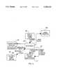
- FIG. 1is a block diagram showing the organization of a television broadcast station incorporating the encoding and monitoring system of the illustrated embodiment of the invention.
- FIG. 2is a block diagram of the encoder system in accordance with the illustrated embodiment of the invention.
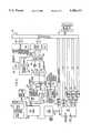
- FIG. 3is a schematic diagram of the encoder of the illustrated embodiment of the invention.
- FIG. 4is a block diagram of an alternative encoding arrangement in accordance with the invention.
- FIG. 5is a block diagram of the decoder system in accordance with the illustrated embodiment of the invention.
- FIG. 6is a schematic diagram of a decoder in accordance with the invention.
- a programwhich might be a commercial or other program material, may be received at a television station in the form of a video tape shipped to the station, or it may be transmitted electronically by satellite. In the case of satellite transmission, the program is recorded as received at the station on video tape. In either case, the video tape is delivered to the station's traffic department and information, which in the case of a commercial would typically include the title, advertiser, advertising agency, identifying codes and duration of the commercial, is entered into the traffic computer 13 and matched against data concerning a related contract or program schedule stored therein.
- the video tapeAfter being processed by the traffic department, in the case of a commercial, the video tape is sent to the engineering department to be dubbed onto a tape cartridge which is compatible with the station's video tape library management system 15.
- the dubbingis performed under the control of a dubbing computer 17 by an input video tape drive 19 which is coupled to a video cartridge recorder 21.
- the tapes sent to be dubbedmay be accompanied by a digital floppy disk or a handwritten dubbing information form.
- the information from the traffic departmentmay be transferred by local area network between the traffic computer 13 and the dubbing computer 17.
- pertinent information about the program recorded on the video tapeincludes, in the case of a commercial, the ISCI code or episode code, the name and duration of the program, the advertiser, and the advertising agency.
- the traffic computeralso normally specifies the number of the cartridge on which the tape is to be dubbed.
- the dubbing computer 17controls the input video tape drive 19, which is typically a reel-to-reel machine, and the output video cartridge recorder 21 to dub the program from the video tape onto a video tape cartridge.
- Information concerning a plurality of commercialsis normally sent to the dubbing computer 17 at one time by the traffic department by means of the floppy disk or local area network.
- the dubbing operatorcalls up the data on the dubbing computer 17 relevant to the program recorded on the next video tape to be dubbed. This information is typically used to prepare a label for the dubbed cartridge on which the program is recorded and is stored in an inventory database managed by the dubbing computer 17.
- the labelmay contain various information depending on the station set up and equipment.
- the label informationnormally includes, however, the number of the cartridge assigned by the traffic computer in both human and machine readable form.
- the dubbing computer 17, the input video tape drive 19 and the output video tape cartridge recorder 21are normally standard components commonly used in television broadcast stations for dubbing incoming programs for the library management system 15.
- Tape drives suitable for use as the input tape drive 19are available from suppliers such as Ampex, Sony and RCA.
- Cartridge recorders suitable for use as the output video tape cartridge recorder 21are available from Sony, Ampex and other suppliers.
- the format and configuration of the video tape cartridgeshould be compatible with the video tape library management system 15 as will be described in more detail below.
- the dubbing computer 17can typically be a 386 level personal computer or similar machine.
- the computer programs resident in the dubbing computer 17 for controlling the video tape drives 19 and 21 and for maintaining the inventory databaseare commercially available from the suppliers of video tape library management systems.
- the encoding of incoming programs with an identification code for later detection during broadcastis accomplished simultaneously with the dubbing of the program onto the cartridge by means of the encoder system 23 which is connected between the output of the video tape drive 19 and the input of the tape cartridge recorder 21 for encoding a selected line of the overscan region of the program's video signal with an identification code.
- the identification code and other information needed for the encodingis sent to the encoding system 23 by the dubbing computer 17.
- the cartridgesare either stored in the management system 15 or in the station's video cartridge library in a location determined by the number assigned by the traffic computer.
- the video tape library management system 15includes a plurality of video tape drives (typically 6 to 8), a storage system for storing a plurality of tape cartridges, and a robotic system for automatically selecting cartridges from the storage system and loading each selected cartridge onto one of the tape drives for playing the commercial recorded thereon. After the commercial has run, the robotic system removes the cartridge from the drive and returns it to the proper location in the storage system.
- An elaborate cartridge library management systemcan store and control as many as 1,000 tape cartridges, each having recorded thereon a single commercial.
- a typical network affiliate broadcast stationwill have about 2,000 tape cartridges in its inventory, each such cartridge storing a single commercial.
- An independent television broadcast stationwill typically have about 1,000-1,500 of such cartridges in its inventory.
- a primary network broadcast stationmay have 10,000 or more cartridges.
- Video tape library management systemsare part of a television station's normal equipment and are available from various suppliers, such as Sony, La Kart and Ampex.
- a "station”may refer to a broadcast or cable network originating station or to a network affiliate or independent broadcast station.
- Broadcastcan refer to either broadcast or cable transmission.
- a play listis sent by the traffic computer 13 to the library management system 15 by floppy disk or local area network.
- the play listis an ordered listing the numbers of the video tape containing cartridges which are to be broadcast by the station during a particular time period.
- the library management system 15compares the play list with its list of the cartridges which it has stored and prints out a list of the numbers of the cartridges which it is missing. If the library management system internal storage space is full, it selects the stored cartridges which it has not played for the longest period of time and ejects a sufficient number of those cartridges to make room for the needed new ones. As the new cartridges are inserted into the library management system, the robotic system reads the machine readable number (normally a bar code) and stores it in an available location.
- machine readable numbernormally a bar code
- the output of the video tape library management system 15is connected to a video switcher 25, which selects among various inputs to be connected to the transmitter 27.
- the video tape management systemis connected by the video switcher 25 to the transmitter 27.
- Other inputs to the video switcher 25typically would include a network feed (for network affiliated stations), a connection from the station's newsroom, and a connection for video taped syndicated shows, among others.
- the transmitter 27broadcasts the television programs by means of the antenna 29.
- the signal broadcast by the antenna 29is preferably monitored at the station 11 by means of tuner/decoder 31.
- the tuner/decoder 31receives the broadcast signal from the antenna 29 and monitors the video signal to detect and decode the identification codes recorded by the encoder 23.
- the identities of the encoded programs and the time and duration of their transmissionis stored by the tuner/decoder for transmission to a remote host computer.
- the stationis not well located for receiving the broadcast signal from the antenna 29.
- a tuner/decoder 33may be connected to a tap on the antenna 29 to detect and decode the broadcast signal.
- references to the "station”also include the site of the antenna 29.
- the encoder system 23includes a 386 type personal computer or similar machine 35 preferably having at least 4-megs. of internal memory and a solid state disk drive.
- the encoder 37may take the form of a circuit board installed in an expansion slot of the computer 35.
- a 9600 baud modem 39is also connected to the computer 35, preferably as another expansion slot board.
- the modem 39connects the computer 35 to the host computer.
- the encoder 37has an input terminal connected to the video output of the input tape drive 19 (FIG. 1) and an output terminal connecting the encoded video to the output video tape cartridge drive 21.
- the encoded video signalmay also be connected to a video monitor 41 which includes a character generator, for displaying both the video signal of the program being encoded and the alpha numeric display of the characters being encoded on the selected line.
- FIG. 3 of the drawingsthere is shown a schematic diagram of the encoder 37.
- the video signal from the input video tape drive 19(FIG. 1) is connected to the input of the amplifier 43 through the video input terminal 45.
- the output of the amplifier 43is connected to the input of a gain control amplifier 47 and to a sync strip circuit 49.
- Sync strip circuit 49detects the presence of the vertical and horizontal sync pulses on the input video and develops outputs coincident in time with the presence of such signals on the input.
- the circuit 49also develops other outputs temporally coincident with the location of the color burst and back porch.
- the sync strip circuit 49is implemented by a NS 1881 semiconductor chip available from National Semiconductor Co.
- the sync strip circuit 49also develops an output which indicates whether the odd or even field of each frame is present at the input 45.
- the outputs of the circuit 49 corresponding to the vertical sync, horizontal sync and color burst and back porchare connected to the line detect circuit 51.
- An output of the line detect circuit 51is connected to the normally open grounding switch circuit 53 for selectively grounding the output of the amplifier 43 during the color burst and back porch signals.
- the encoder 37is connected directly to the bus of the computer 35 (FIG. 2) by the bus logic 53.
- the output of the bus logic 53is connected to a series of registers which include the scan line register 55, the preamble register 57, two code byte registers and 59 and 61, each of which are 11 bytes long, and a control register 63.
- the scan line register 55stores the number of the line in the video scan which is to be encoded by the encoder board 37 with the identification code in accordance with the invention. Preferably a line between numbers 10 and 20 is selected by the scan line register 55 for encoding under the control of the computer 35.
- the preamble register 57stores a one byte preamble code.
- the code byte registers 59 and 61are each used to store a 10 byte identification code and a one byte cyclic redundancy check code.
- the preamble, identification code and cyclic redundancy check byteare received from the computer 35 via the PC bus logic 53 for each program to be encoded.
- the control register 63acts under the control of the computer 35 to enable the encoder board 37 to begin encoding the selected line of the video input signal.
- the output of the scan line register 55is connected to the line detect circuit 51.
- the output of the preamble register 57is connected to the one byte code shift register 65.
- the outputs of the code byte registers 59 and 61are also connected to the code shift register 65 through the odd/even select circuit 67.
- the odd/even output of the sync strip circuit 49is connected to the odd/even detect circuit 67 to control the selection of which of the two code byte registers 59 and 61 is coupled to the code shift register 65 at any time.
- An output of the line detect circuit 51is connected to counter 66 to enable the counter to count clock pulses from the phase lock loop clock 68.
- the output from the counter 66is connected to the code shift register 65 for enabling it at the appropriate time.
- the horizontal sync pulse output from the sync strip circuit 49is connected to the clock 68 for phase locking the clock 68 to the horizontal sync pulses which define the video scan line timing.
- the phase lock loop clock 68divides the scan line into 128 bit times between successive horizontal sync pulses.
- the clock 68includes a 12 Mhz clock oscillator whose frequency is divided to provide a very stable 2M hz output to the counter 66 and to the code shift register 65 for controlling their operation.
- the code shift register 65includes a framing bit generator 70 for generating a one bit framing pulse to mark the beginning of the coding data for the scan line being encoded.
- the output of the level controlling amplifier 47is connected to the input of an amplifier 69 through a normally closed series switch 71.
- the series switch 71is controlled by a control output from the line detect circuit 51.
- the shift register 65has a serial code output which is connected to control the operation of a bi-level switching circuit 73 which develops an output of either 5 volts or ground depending upon the level of its input from the code shift register 65.
- the output of the switching circuit 73is connected to the input of a level setting amplifier 75 whose output is connected to the input of the amplifier 69 through a normally open switch 77.
- the control output of the line detect circuit 51is also connected through an inverter 79 to control the operation of the switch 77 in order to selectively connect the level setting amplifier 75 to the input of amplifier 69.
- the switch 82which is held open by the V BB supply voltage, is connected between the input terminal 45 and the output terminal 81. Switch 82 closes when the V BB supply voltage is removed from the encoder 37 for bypassing the encode
- the encoded scan line dataconsists of the framing bit followed by 96 bits of data. Each bit is either 1, represented by a 70 IRE voltage level or a 0, represented by a 0 IRE voltage level.
- the voltage excursion of the video signalis arbitrarily divided into 100 levels with 100 IRE corresponding to the brightest white and 0 IRE corresponding to pure black.
- the 70 IRE used in the illustrated embodiment of the present invention to represent a binary 1gives adequate differentiation from the 0 IRE level representing a binary 0 for easy detection while not risking overdriving the video circuitry.
- the framing bitwhich is always a binary 1, follows the horizontal sync pulse on the encoded scan line.
- the framing bitis recognized by the decoding circuitry as the beginning of an encoded scan line and initiates the decoding of the line.
- a one byte preamble codewhich, in the illustrated embodiment, is a two digit hexadecimal number which can be used to specify the significance of the data bytes on the remainder of the line as, for instance, identifying a particular commercial or syndicated program.
- the preamble codeare ten bytes of data which identify the encoded program.
- a one byte cyclic redundancy check or error codefollows the 10 data bytes.
- the 10 data bytesare the 8 bytes international standard commercial identification (“ISCI") code which uniquely identifies the encoded commercial, followed by two bytes used to identify the advertising agency or provide other information.
- ISCIinternational standard commercial identification
- the first four bits of the ISCI codeare capital alpha letters and the following four bytes are numbers.
- each frame of the video information of the encoded programIt is preferred in the illustrated embodiment of the invention to encode both fields of each frame of the video information of the encoded program with the identification code. It is possible, however, to encode only the odd or even field of each frame, or to encode the two fields of each frame differently. If the two fields are encoded differently, then each frame could be encoded with 20 data bytes. It would also be possible to encode one field of each frame with the program identification and to use the second field as a counter. Such an arrangement is useful in cases such as that in which a commercial is embedded in a syndicated program and the broadcast station is contractually obligated to run the commercial even if the syndicated program is not.
- the input video signal from the input video tape recorder 19(FIG. 1) is amplified by the amplifier 43, level adjusted by the amplifier 47 and connected to the video output 81 through the normally closed switch 71 and the amplifier 69.
- the sync strip circuit 49senses the output of the amplifier 43 and develops separate outputs in time correspondence to the presence of vertical sync pulses, the horizontal sync pulses, and the color burst and back porch signals on the video at the output of amplifier 43.
- the line detect circuit 51receives the horizontal sync, vertical sync, and color burst outputs from the sync strip circuit 49 and counts the number of horizontal sync signals occurring after each vertical sync in order to count the lines of the video field as they are present at the output of the amplifier 43.
- the line detect circuit 51compares the field line determined from the vertical and horizontal sync inputs with the scan line number stored in the scan line register 55 to determine when the video scan line to be encoded is present at the output of the amplifier 43.
- the line detect circuit 51is enabled upon the sensing of the horizontal sync signal of the scan line from the sync strip circuit 49 to be encoded such that the trailing edge of the horizontal sync pulse causes the line detect circuit 51 to close the normally open switch 53 until the trailing edge of the back porch output pulse from the sync strip circuit 49, at which time the switch 53 is opened again.
- the closing of the switch 53grounds the output of the amplifier 43, thereby blocking the transmission of the 3.6 Mhz color burst signal which otherwise would generate noise on the encoded signal.
- the end of the back porch of the line to be encodedalso causes the output of the line detect circuit 51 connected to the switch 71 to go high for the remainder of the scan line. This opens switch 71 and closes switch 77 for the remainder of the scan line, thereby disconnecting the amplifiers 43 and 47 from the video output 81 and connecting the code switch circuit 73 to the video output 81 through the amplifiers 75 and 69.
- the line detect circuit 51At the same time as it closes the switch 53 and opens the switch 71, the line detect circuit 51 generates the Start Code signal for initiating the encoding of the remainder of the scan line. Since the phase lock loop clock 68 divides the scan line into 128 bit spaces and the information to be encoded onto the line occupies only 97 bit spaces, there is some extra room on the scan line. In order to allow for possible phase shift resulting, for instance, from time base corrections performed by the television broadcast station, it is preferred to position the information encoded on the scan line roughly in the middle of the available space. This objective is accomplished on the illustrated embodiment of the invention by using the counter 66 to delay the beginning of the encoded portion of the scan line so that approximately equal space exists between the beginning and end of the encoded data and the preceding and following and horizontal sync pulses, respectively.
- the Start Code signal generated by the line detect circuit 51enables the counter 66 to begin counting bit time defining clock pulses from the clock 68.
- the counter 66generates an output to the code shift register 70 after counting 32 clock pulses, thereby defining a 4 byte wide space between the point where the switch 71 is open and switch 77 closed and the beginning of the encoding.
- the code shift register 65begins serially transmitting code data bits, one for each clock cycle of the clock 68, to the control input 72 of the switching circuit 73.
- the framing bit generator 70causes a binary 1 to be transmitted to the switching circuit 73.
- the code shift register 65is initially loaded with the contents of the preamble register 57.
- the code shift register 65serially transmits the preamble code to the switching circuit 73.
- the odd/even select circuit 67controls the transfer of code bytes from either code byte register 59 or 61 to the code shift register 65. The bytes are shifted from the code byte registers 59 or 61 one byte at a time in parallel.
- the bits of the first code byteare shifted out of the code shift register 65 during the 10th through 17th clock pulses received by the code shift register 65 from the clock 68 after being enabled by the counter 66. This process of transferring the code bytes one at a time to the shift register 65 and then serially transmitting those bits to control the switching circuit 73 continues until all ten code bytes and the cyclic redundancy check byte have been transmitted.
- the control input 72 of the switching circuit 73For each binary 1 bit transmitted by the code shift register 65, the control input 72 of the switching circuit 73 is high for the entire bit time. This causes the switching circuit 73 to connect its output to the five volt supply. When a zero bit is transmitted from the code shift register 65 the control input 72 is held low for the entire bit period, which in turn causes the output of the switching circuit 73 to be connected to ground.
- the amplifier 75is adjusted such that when its input is at five volts, its output is at 70 IRE. When its input is grounded, the output is at 0 IRE.
- the output of the amplifier 75is connected to the video output 81 of the encoder 37 through the amplifier 69.
- the data from the code shift register 65is transmitted as a binary bit stream to the video output 81 of the encoder 37 in which a 1 is a 70 IRE level and a 0 is a 0 IRE level.
- the alternative encoding system 23'may be used to encode television programs in accordance with the invention.
- the encoding system 23is substantially identical to the encoding system 23 illustrated in FIGS. 1 and 2 of the drawings. In the case of the embodiment of FIG. 4, however, the functions of the dubbing computer 17 are taken over by the computer which forms part of the encoding system 23'.
- the information concerning the programs to be encodedis entered into the computer of the encoding system 23' by means of either of floppy disk drive 83 or the keyboard 85.
- Display 87is connected to the computer in the encoder system 23' for use by the dubbing operator.
- a label printer 89is connected to the computer in the encoder system 23' for preparing labels identifying the contents of the video cartridges being recorded at the video cartridge drive 21.
- an output 91 from the computer in the encoder 23'is connected to the output video cartridge recorder 21' for sending video tape cuing codes to the cartridge recorder for being recorded on the initial portion of the tape in the cartridge.
- the decoder system 93is similar in basic configuration to the encoder system 37 (FIG. 2). It includes a 386 level personal computer 95 preferably having at least 4 Megs. of internal random access memory and a solid state disk 96.
- the decoder board 97is preferably configured to be plugged into one of the expansion slots of the computer 95.
- a 9600 baud modem 99is also preferably connected in one of the expansion slots of the computer 95.
- the decoder system 93receives the video input signal from the tuner/decoder system 31 or 33 and monitors all video scan lines between lines 10 and 50 of each field of the video signal.
- the decoder system 93sees one such line encoded in accordance with the encoding arrangement of the illustrated embodiment of the invention, it separates the data on the encoded scan line from the composite video signal and assembles the scan line data records for each encoded program detected.
- Such recordsare stored in the solid state disk drive 96 in a database managed by the computer 95. These records also include data specifying the time at which the program commenced and the duration of the program in terms of the number of consecutive fields on which the data is encoded.
- the record for each encoded program detectoralso preferably includes the number of the encoded line and a quality index for the encoded video signal.
- These recordare stored on the solid state disk 96 under control of a database management system for later retrieval by the host computer through the modem 99.
- the stored datais preferably retrieved from both the encoder system 23 and the decoder system 93 on a daily basis by the host computer which is normally at a remote site.
- the data from a particular stationmay be combined with similar data from other stations in the same or other markets to create an occurrence database of programs which are run locally and nationally.
- the data from the decoder system 93is also sent to the traffic computer 13, preferably by a local area network, for use by the station traffic department in correlating the programs and commercials actually transmitted with contracts for billing and monitoring purposes.
- the quality indexis determined by a programmable algorithm according to which the failure to find a encoded line on a preselected number of consecutive frames, typically set at about 60, or the absence of color burst results in a reduced quality index. If the identification code is missing from more than the preselected number of consecutive frames, the encoded video following the break is treated as a separate program.
- the decoder system 93can also receive and store the as-aired log from the station control console computer by monitoring the output of the control console computer to an as-aired printer which printer prepares reports of the as-aired log.
- the as-aired logmay be later retrieved via the modem 99 by the host computer.
- the as-aired logallows automatic testing of occurrences of commercials and programs against the decoder occurrences recorded. This testing at the host computer assures accuracy of the database information and eliminates problems with last minute changes in commercial schedules that do not always get recorded at the control console computer.
- the availability of the as-aired log informationalso allows greater differentiation of the source of a common commercial use by both local, regional and national advertising agencies.
- the information at the host computeris combined with information from other databases and various statistical reports are compiled for use by the broadcast stations, advertisers and advertising agencies either by hardcopy or on-line access to the host computer.
- the decoder 97consists of a control portion made up of the I/O CPU 101 and associated registers and memory, and a tuner/decoder section made up of the tuner 103 and the associated decoding circuitry which receives the television signal broadcast by the transmitting station, determines the presence of a scan line encoded in accordance with the illustrated embodiment of the invention and decodes the information present on the scan line.
- An 8 bit data bus 105interconnects the various circuits on the decoder board 97 and acts as the communication path among them. Communication between the decoder 97 and the computer 95 of the decoder system 93 (FIG. 5) takes place via the universal asyncronous receive and transmit circuit ("UART") 107.
- the reset circuit 109When power is turned on, the reset circuit 109 generates a power-up signal which resets the various circuits on the decoder 97 to an initial condition.
- the power-up signalcauses the I/O CPU 101 to go to the "boot mode" in which it is able to communicate with the computer 95 through the UART 107, but is otherwise waiting.
- the I/O CPU 101receives instructions from and transmit data to the computer 95 through the data register 111 and the data bus 105 on an 8 bit wide path.
- the 8K ROM 113stores code for interpreting the commands received from the computer 95 when the I/O CPU 101 is in the boot mode.
- the boot mode commands received from the computer 95cause the I/O CPU 101 to address the locations in the ROM 113 which store the microcode needed to interpret and execute each command.
- the I/O CPU 101addresses the ROM 113, the 32K EEPROM 115 and the 64K SRAM 116 through the address register 118. Since the addressing of these memories requires 16 bits, two 8 bit bytes are sent by the I/O CPU to the address register 116.
- the boot mode commandsinclude a "Send Status" command which causes the I/O CPU 101 to tell the computer 95 whether it is in the boot or operational mode.
- the "Go Operational” commandcauses the I/O CPU 101 to switch from the boot mode to the operational mode.
- the UART 107is connected to the computer 95 through an RS 232 interface and serially transmits or receives data one byte at a time to or from the computer 95.
- Informationis sent by the I/O CPU 101 to the computer 95 one byte at a time in response to the receipt from the computer 95 of "clear to send" signal Ion the CTS line to the UART 107.
- the receipt of the CTS signalcauses the UART 107 to generate a first level interrupt to the I/O CPU 101 which in turn causes the I/O CPU 101 to address the SRAM 116 to send the next data byte to the computer 95 through UART 107.
- This mode of operationpermits the computer 95 to handle other matters when it needs to without risk of compromising the integrity of the data which is being sent to it by the I/O CPU 101.
- the I/O CPU 101When the I/O CPU 101 enters the operational mode, it shifts to the EEPROM 115 to interpret commands received from the computer 95 and sends the channel number received from the computer 95 as part of the Go Operational command to the channel register 117 through the data register 111 and bus 105.
- the Go Operational commandalso includes a filter byte which programmatically controls I/O CPU 101 on the criteria for recognizing the reception of encoded fields as the beginning of an encoded program, and for determining whether a series of encoded fields represents one or more programs. The first two bits of the filter byte determine how many successive encoded fields must be found before the I/O CPU 101 determines that an encoded program is being received.
- bitsare normally set such that two successive encoded fields (one frame) are required before the beginning of a program is recognized, but if the station is particularly noisy, the filter byte can specify a larger number, eg. four fields (two frames), which must be found before the beginning of a program is recognized.
- the systemtime stamps the start of the program based on the first encoded field but must recognize the required number of successive encoded fields before the reception of an encoded program is confirmed.
- the other six bits of the filter byteare used to set the number of dropped fields which can occur before the information following the dropped fields is considered to be a different program. Typically, these bits are set to specify 180 fields (3 seconds) but different numbers of fields can be set as desired.
- the filter bitsare set at 180 fields, and the dropping of 180 or fewer fields occurs, the encoded segments before and after the dropped fields are considered to be a single program but the quality index is decreased. This of course assumes that the fields before and after the gap are encoded with the same codes. If more than 180 fields are dropped in succession, the two encoded segments proceeding and following the dropped fields are considered to be two separate programs.
- the output of the channel register 117is connected to tuner CPU 119 which controls the tuner 103.
- the channel numberis stored in the channel memory portion of the tuner CPU 119 where it is used to tune the tuner 103 to the proper frequency.
- the Video Lost input to the tuner CPU 119is set.
- the tuner CPU 119causes the tuner 103 to scan back and forth over a 2 megahertz band centered on the channel frequency in order to find the video signal as soon as it comes back on.
- Scanning over a 2 megahertz bandenables the system to be used with cable stations which may be transmitting a particular channel on any one of three different frequencies within a 2 megahertz band about a nominal center frequency, depending upon the particular cable network arrangement.
- narrower scanning bandscould be used because the station frequency never varies more than about 10 kilohertz from the nominal channel frequency.
- the video output of the tuner 103is connected to a sync strip circuit 121 which may be identical to the sync strip circuit 49 of the encoder 37 (FIG. 3).
- the sync strip circuit 121senses the vertical sync and the horizontal sync pulses on the video input and generates output pulses at times of the vertical and horizontal sync pulses and of the back porch for use in the decoding operation.
- the sync strip circuit 121also generates an output specifying whether the odd or even field is present.
- the horizontal sync outputis connected to a filter 123 which generates a squared stable horizontal sync output for use by the line parser circuit 133.
- the video output from the turner 103is also connected through the amplifier 125 to the sample and hold DC restore circuit 127.
- the back porch output of the sync strip circuit 121is also connected to the sample and hold circuit 127 to cause it to sample the voltage level of the video signal at the output of amplifier 125 at back porch time and hold that level until the back porch of the next video line in order to provide a DC reference level for decoding the information on the video signal.
- the DC level in the decoder 97 of the received video signalscan float over a relatively wide voltage range.
- the sample and hold circuit 127provides a reference equal to the back porch voltage level, which is substantially 0 IRE.
- the phase lock loop video clock 129may be similar to the clock 68 in the encoder circuit, (FIG. 3).
- the clock 129generates a 2 Mhz output which is phase locked to the H sync output of the sync strip circuit 121 in order to divide the video line into 128 bit times from H sync to H sync.
- the output of the video clock 129is connected to the counter 131 which is in turn connected to the line parser circuit 133.
- the counter 131counts the 128 clock pulses on each video line and is reset at the end of each line.
- the line parser 133also receives the video output from the amplifier 125.
- the line parser 133monitors each video line to determine whether the various portions of the line are present and in the appropriate time slots.
- the V bit valid output of the line parser 133is high during the period that valid data bits can be present on the encoded scan line. This occurs from the end of the back porch time until close to the end of the scan line.
- the timing generator circuit 135receives a 12 Mhz output from the video clock and the V sync and H sync pulse outputs from the sync strip circuit 121, and generates a plurality of timing pulses for controlling the timing of various parts of the decoder 97.
- One such outputis a sampling pulse which is generated at the middle of each of the 13 bit time periods after porch time for lines 10 through 50 of each field.
- This sampling pulse outputis connected to the line parser 133 and causes it to sample the video level at the center of each such bit time period to look for the framing bit.
- the line parser 133sees a high video voltage level at the sampling time, it sets its sync bit output high, tentatively indicating that a framing bit is present.
- the video output of the amplifier 125is also connected to an input of the video bit comparitor 137, the H sync comparitor 139 and the color burst detector 141.
- the output of the DC restore circuit 127is connected to the other inputs of the comparitors 137 and 139.
- the output of the H sync comparitor 139is connected to the line counter circuit 143.
- the output of the video bit comparitor 137is connected to the shift register 145 and to the cyclic redundancy check circuit 147.
- a serration detector included in the timing generator circuits 135generates an output, referred to as "Large Kick" during the serration time the serrations are the H sync pulses that occur during the first 10 lines in the vertical blanking interval. They are more closely spaced in time than the H sync pulses for the other scan lines and the first five of them are positive going. The beginning of the serration time is contemporaneous with the V sync pulse.
- the serration detectorrecognizes the serrations by the fact that the counter 131 does not get close to the 128 count between adjacent H sync pulses.
- the Large Kick signaldisables the phase lock loop in the clock 129 and the line parser circuit 133 and resets the line counter 143 to 10.
- the phase lock loop and the line parser circuit 133are once again enabled and the line counter 143 begins counting H sync pulses starting with line 11.
- the comparitor 139is able to recognize H sync pulses by virtue of the fact that they are the only negative going pulses.
- the sync bit output from the line parser 133is connected to the shift register 145 for enabling the shift register 145 to begin shifting in the code bits which immediately follow the framing bit in successive bit times.
- the decoder 97compares the first byte following the framing bit with the preselected preamble codes stored in the preamble memory 148 to determine whether a valid preamble is present.
- the comparitor 149is connected to the first bit location in the shift register 145.
- the comparitor 149compares the first video bit with the first bits of the preambles stored in the memory 148 and eliminates the stored preambles which do not match. During subsequent bit times the comparitor 149 compares the successive bits in the first location in the shift register 145 with the corresponding successive bits of remaining matching stored preambles until all stored preambles are eliminated or a match is found. If no match is found, the line is considered to be ordinary video and the shift register 145 is disabled. In such event the line parser 133 continues to look at subsequent lines seeking to find another potential framing bit.
- the Video Data FIFO 151contains a 16 eight-bit registers and may be implemented as an AM 29525 integrated circuit which is manufactured by AMI Inc. Only 13 of the 16 registers are used in the illustrated embodiment to store the information from the encoded line and the number of the encoded line.
- the 10 identifying eight-bit bytes and the CRC byte on the encoded line of the received programare then serially shifted into the shift register 145 through the video bit comparitor 137.
- each eight-bit byteis shifted into the register 145, it is transferred in parallel into the next available register of the Data FIFO 151 until all 10 information bytes and the CRC byte are resident in the registers of the FIFO 151.
- the sync bit from the line parser 133also enables the cyclic redundancy check circuit 147 to begin receiving the video bits of the encoded line.
- the output of the cyclic redundancy check circuit 147is zero if the data on the encoded line is correct. If an error has occurred, the output of the cyclic redundancy check circuit 147 is other than zero at the end of the last bit time of the encoded CRC byte.
- Video Data FIFO 151transfers the CRC byte from the shift register to the 12th register of the FIFO 151, it also disables the shift register 145, stops the reading of video bits by the cyclic redundancy check circuit 147, and loads the contents of the line counter 143 into the 13th FIFO register.
- the FIFO 151then enables the cyclic redundancy check circuit 147 such that, if its output is zero, it generates a level zero interrupt (referred to as FIFO RDY) to the I/O CPU 101.
- the I/O CPU 101causes the contents of the FIFO 151 to be transferred to the SRAM 116 via the data bus 105.
- the SRAM 116receives the information recorded on the selected scan line of the encoded television program along with the number of the line on which it was encoded.
- the data stored in the FIFO 151is not transferred to the SRAM 116 but is discarded. If this happens at a field of an encoded program, it is treated as a dropped field for purposes of the quality index calculation.
- the line counter 143If the contents of the line counter 143 reaches 50 without any encoded line having been found, it ceases counting and disables the shift register 145. In such case the field being received is assumed not be encoded.
- the encoded line data received by the SRAM 116is compiled by the I/O CPU 101 into a series of records, one for each encoded program decoded by the decoder 97.
- Each such recordcontains the identification data for the encoded program, the start time and the duration of the program in terms of the number of encoded fields which it contains and the quality index for the program.
- the computer 95commands the decoder 97 to send to the host the information stored concerning the encoded programs which have been monitored by the decoder 97.
- the computer 95sends to the I/O CPU 101 the "Read Status" command which causes the I/O CPU 101 to send back a status byte.
- the first bit of the status bytespecifies that the I/O CPU 101 is in the operational mode.
- the second bitreferred to as the "pending" bit, tells whether or not there is at least one complete program which has been monitored and the record of it stored in the SRAM 116.
- the third bit of the status bytespecifies whether the I/O CPU 101 is currently decoding a program. If the pending bit is set, the computer 95 can command the I/O CPU 101 to send the pending records from the SRAM 116 to the computer 95 starting with the earliest record.
- the SRAM 116is programmatically organized in a series of successive registers, each clapable of storing the record of one monitored program. Addresses for the registers in the SRAM 116 are arranged in a ring, such that if the address of the highest numbered register is incremented, the address becomes that of the lowest numbered register.
- the I/O CPU 101maintains in one memory location the address of the register in SRAM 116 containing the next pending record to be sent to the computer 95. A second location stores the address in the SRAM 116 of the register in which the record of a program presently being decoded is being compiled, or if no program is being decoded, the address of the next available register in SRAM 116 in which a new encoded program record can be stored.
- the I/O CPU 101When the computer 95 instructs the I/O CPU 101 to send the pending records of completed decoded programs to it, the I/O CPU 101 successively sends the pending records via the UART 107 to the computer 95, incrementing the address of the register for each successive pending record, until the address of the register storing the next pending record becomes equal to the address in the second location of the register where the record of the next program to be decoded is to be stored. This condition occurs when the registers in SRAM 116 are empty.
- the SRAM 116When, during reception of successive encoded programs, the address in the second location becomes equal to that of the pending record in stored the first location, the SRAM 116 is full. If additional programs are decoded when the registers in the SRAM 116 are full, the data for the newly received programs is discarded.
- the SRAM 116can store the records of up to 1440 programs in its registers, which corresponds to two full days of 15 second encoded programs. Since the computer 95 normally retrieves the records of the decoded programs from the decoder 97 at least once per day, the problem of the registers of the SRAM 116 becoming full normally does not occur.
- the decoder 97is also capable of decoding base band video signals at the station. If the channel number sent to the channel register 117 by the I/O CPU 101 calls for channel 0, the tuner CPU 119 shuts off the tuner 103 and the base band video is received at terminal 153. The received base band video is connected to the sync strip circuit 121 and the amplifier 125, and it is thereafter treated in the same manner as video signals received by the tuner 103.
- the status register 155is an 8 bit register which can be read by the I/O CPU 101 thereby allowing the I/O CPU to monitor the operation of important components of the decoder 97.
- the +30, -6 and +9 volt suppliesare generated on the decoder board by the regulator 154.
- the porch signalis received from sync strip circuit 121.
- the color burst time signal from the line parser 133 and the color burst pulse on the output of the detection circuit 141are connected to an AND gate (not shown) whose output is connected to the burst valid input of the status register 155.
- the odd/even output of the sync strip circuit 121is connected to the odd/even input of the status register 155.
- the contents of the status register 155are polled by the SRAM 116 frequently during operation of the decoder 97.
- the odd/even output of the sync strip circuit 121can be used to enable the line counter 143 and shift register 145 only during the odd or even field as appropriate. In systems where the odd and even fields are encoded differently, the odd/even output of the sync strip circuit 121 can also be used to differentiate between the two fields.
- the system of the present inventionhas many advantages over those proposed in the prior art.
- the fact that it is an in-station system in which the encoding, and preferably both the encoding and decoding is performed locally at the stationpermits the particular line to be encoded to be selected so as not to interfere with other operations of the station and to avoid problems with stripping. It is possible also to use the system to monitor programs broadcast by a station which programs have been encoded at the originating network or syndicator.
- the system of the inventioncan easily distinguish between such sources by, for instance, having different sources encode different lines of the video signal or by the use of appropriate preamble codes for different types of sources.
Landscapes
- Engineering & Computer Science (AREA)
- Signal Processing (AREA)
- Multimedia (AREA)
- Television Signal Processing For Recording (AREA)
- Testing, Inspecting, Measuring Of Stereoscopic Televisions And Televisions (AREA)
- Two-Way Televisions, Distribution Of Moving Picture Or The Like (AREA)
- Management Or Editing Of Information On Record Carriers (AREA)
Abstract
Description
Claims (27)
Priority Applications (7)
| Application Number | Priority Date | Filing Date | Title |
|---|---|---|---|
| US07/796,008US5450122A (en) | 1991-11-22 | 1991-11-22 | In-station television program encoding and monitoring system and method |
| ES92925369TES2126607T3 (en) | 1991-11-22 | 1992-11-20 | IN-STATION SYSTEM AND METHOD FOR CODING AND MONITORING A TELEVISION PROGRAM. |
| EP92925369AEP0617871B1 (en) | 1991-11-22 | 1992-11-20 | In-station television program encoding and monitoring system and method |
| CA002123995ACA2123995C (en) | 1991-11-22 | 1992-11-20 | In-station television program encoding and monitoring system and method |
| AT92925369TATE176114T1 (en) | 1991-11-22 | 1992-11-20 | SYSTEM AND METHOD FOR CODING AND MONITORING A TELEVISION PROGRAM |
| DE69228258TDE69228258T2 (en) | 1991-11-22 | 1992-11-20 | SYSTEM AND METHOD FOR CODING AND MONITORING A TELEVISION PROGRAM |
| PCT/US1992/010062WO1993010630A1 (en) | 1991-11-22 | 1992-11-20 | In-station television program encoding and monitoring system and method |
Applications Claiming Priority (1)
| Application Number | Priority Date | Filing Date | Title |
|---|---|---|---|
| US07/796,008US5450122A (en) | 1991-11-22 | 1991-11-22 | In-station television program encoding and monitoring system and method |
Publications (1)
| Publication Number | Publication Date |
|---|---|
| US5450122Atrue US5450122A (en) | 1995-09-12 |
Family
ID=25167019
Family Applications (1)
| Application Number | Title | Priority Date | Filing Date |
|---|---|---|---|
| US07/796,008Expired - LifetimeUS5450122A (en) | 1991-11-22 | 1991-11-22 | In-station television program encoding and monitoring system and method |
Country Status (7)
| Country | Link |
|---|---|
| US (1) | US5450122A (en) |
| EP (1) | EP0617871B1 (en) |
| AT (1) | ATE176114T1 (en) |
| CA (1) | CA2123995C (en) |
| DE (1) | DE69228258T2 (en) |
| ES (1) | ES2126607T3 (en) |
| WO (1) | WO1993010630A1 (en) |
Cited By (90)
| Publication number | Priority date | Publication date | Assignee | Title |
|---|---|---|---|---|
| US5584050A (en)* | 1994-03-25 | 1996-12-10 | A.C. Nielsen Company | Program monitoring system |
| US5675355A (en)* | 1996-06-18 | 1997-10-07 | The United States Of America As Represented By The Secretary Of The Army | Automated coherent clock synthesis for matrix display |
| US5745604A (en) | 1993-11-18 | 1998-04-28 | Digimarc Corporation | Identification/authentication system using robust, distributed coding |
| US5748763A (en) | 1993-11-18 | 1998-05-05 | Digimarc Corporation | Image steganography system featuring perceptually adaptive and globally scalable signal embedding |
| US5748783A (en) | 1995-05-08 | 1998-05-05 | Digimarc Corporation | Method and apparatus for robust information coding |
| US5761601A (en)* | 1993-08-09 | 1998-06-02 | Nemirofsky; Frank R. | Video distribution of advertisements to businesses |
| US5809160A (en) | 1992-07-31 | 1998-09-15 | Digimarc Corporation | Method for encoding auxiliary data within a source signal |
| US5822436A (en) | 1996-04-25 | 1998-10-13 | Digimarc Corporation | Photographic products and methods employing embedded information |
| US5826165A (en)* | 1997-01-21 | 1998-10-20 | Hughes Electronics Corporation | Advertisement reconciliation system |
| US5828402A (en)* | 1996-06-19 | 1998-10-27 | Canadian V-Chip Design Inc. | Method and apparatus for selectively blocking audio and video signals |
| US5832119A (en) | 1993-11-18 | 1998-11-03 | Digimarc Corporation | Methods for controlling systems using control signals embedded in empirical data |
| US5841886A (en) | 1993-11-18 | 1998-11-24 | Digimarc Corporation | Security system for photographic identification |
| US5850481A (en) | 1993-11-18 | 1998-12-15 | Digimarc Corporation | Steganographic system |
| US5862260A (en) | 1993-11-18 | 1999-01-19 | Digimarc Corporation | Methods for surveying dissemination of proprietary empirical data |
| US5889548A (en)* | 1996-05-28 | 1999-03-30 | Nielsen Media Research, Inc. | Television receiver use metering with separate program and sync detectors |
| US5974299A (en)* | 1998-05-27 | 1999-10-26 | Massetti; Enrico Emilio | Audience rating system for digital television and radio |
| US6122403A (en) | 1995-07-27 | 2000-09-19 | Digimarc Corporation | Computer system linked by using information in data objects |
| US6173271B1 (en)* | 1997-11-26 | 2001-01-09 | California Institute Of Technology | Television advertising automated billing system |
| US6184918B1 (en)* | 1997-09-30 | 2001-02-06 | Intel Corporation | Method and apparatus for monitoring viewing of broadcast data |
| US6279157B1 (en)* | 1997-03-04 | 2001-08-21 | Sony Corporation | Program data transmission checking method and apparatus |
| US6289514B1 (en) | 1999-03-29 | 2001-09-11 | Qcom Tv, Inc. | System and method for the near-real time capture and reporting of large population consumer behaviors concerning television use |
| US20010042248A1 (en)* | 2000-03-30 | 2001-11-15 | Keisei Yamamuro | Receiver, viewing information recording method, viewing information processor, service contents decision method, information acquisition apparatus, information acquisition method, transmitter/receiver system, and recording media |
| US20020036698A1 (en)* | 2000-09-25 | 2002-03-28 | Koichi Mizutani | Image sensing device |
| US6381341B1 (en) | 1996-05-16 | 2002-04-30 | Digimarc Corporation | Watermark encoding method exploiting biases inherent in original signal |
| US20020059577A1 (en)* | 1998-05-12 | 2002-05-16 | Nielsen Media Research, Inc. | Audience measurement system for digital television |
| US6405370B1 (en)* | 1998-10-09 | 2002-06-11 | Adcom Information Services, Inc. | Television audience monitoring system and method employing tuner interface of set-top converter box |
| US6408082B1 (en) | 1996-04-25 | 2002-06-18 | Digimarc Corporation | Watermark detection using a fourier mellin transform |
| US6424725B1 (en) | 1996-05-16 | 2002-07-23 | Digimarc Corporation | Determining transformations of media signals with embedded code signals |
| US20020104084A1 (en)* | 2001-01-29 | 2002-08-01 | Jennie Ching | Method and system for object retransmission without a continuous network connection in a digital media distributor system |
| US6430302B2 (en) | 1993-11-18 | 2002-08-06 | Digimarc Corporation | Steganographically encoding a first image in accordance with a second image |
| US20020111959A1 (en)* | 2001-02-15 | 2002-08-15 | Jennie Ching | Method and system for file system synchronization between a central site and a plurality of remote sites |
| US20020124246A1 (en)* | 2001-03-02 | 2002-09-05 | Kaminsky David Louis | Methods, systems and program products for tracking information distribution |
| US6560349B1 (en) | 1994-10-21 | 2003-05-06 | Digimarc Corporation | Audio monitoring using steganographic information |
| US6567978B1 (en)* | 1998-10-09 | 2003-05-20 | Adcom Information Services, Inc. | Television audience monitoring system and method employing display of cable converter box |
| US6567533B1 (en) | 1993-11-18 | 2003-05-20 | Digimarc Corporation | Method and apparatus for discerning image distortion by reference to encoded marker signals |
| US6580819B1 (en) | 1993-11-18 | 2003-06-17 | Digimarc Corporation | Methods of producing security documents having digitally encoded data and documents employing same |
| US6581076B1 (en) | 2000-03-29 | 2003-06-17 | International Business Machines Corporation | Method and system for efficient file archiving and dearchiving in a DMD system |
| US6611607B1 (en) | 1993-11-18 | 2003-08-26 | Digimarc Corporation | Integrating digital watermarks in multimedia content |
| WO2003071737A1 (en)* | 2001-12-31 | 2003-08-28 | Measurecast.Com, Inc. | Traffic authentication of verified media programming provided over a computer network |
| US6614914B1 (en) | 1995-05-08 | 2003-09-02 | Digimarc Corporation | Watermark embedder and reader |
| US6625297B1 (en) | 2000-02-10 | 2003-09-23 | Digimarc Corporation | Self-orienting watermarks |
| WO2004004179A1 (en)* | 2002-06-27 | 2004-01-08 | Nagravision Sa | Method for validating the broadcasting conditions of content from a third party |
| US20040025177A1 (en)* | 2002-05-30 | 2004-02-05 | Whymark Thomas J. | Multi-market broadcast tracking, management and reporting method and system |
| US6694042B2 (en) | 1999-06-29 | 2004-02-17 | Digimarc Corporation | Methods for determining contents of media |
| US6721440B2 (en) | 1995-05-08 | 2004-04-13 | Digimarc Corporation | Low visibility watermarks using an out-of-phase color |
| US6728390B2 (en) | 1995-05-08 | 2004-04-27 | Digimarc Corporation | Methods and systems using multiple watermarks |
| US6760463B2 (en) | 1995-05-08 | 2004-07-06 | Digimarc Corporation | Watermarking methods and media |
| US6768809B2 (en) | 2000-02-14 | 2004-07-27 | Digimarc Corporation | Digital watermark screening and detection strategies |
| US6788800B1 (en) | 2000-07-25 | 2004-09-07 | Digimarc Corporation | Authenticating objects using embedded data |
| US20040181799A1 (en)* | 2000-12-27 | 2004-09-16 | Nielsen Media Research, Inc. | Apparatus and method for measuring tuning of a digital broadcast receiver |
| US6804376B2 (en) | 1998-01-20 | 2004-10-12 | Digimarc Corporation | Equipment employing watermark-based authentication function |
| US6804377B2 (en) | 2000-04-19 | 2004-10-12 | Digimarc Corporation | Detecting information hidden out-of-phase in color channels |
| US20040210922A1 (en)* | 2002-01-08 | 2004-10-21 | Peiffer John C. | Method and apparatus for identifying a digital audio dignal |
| US6829368B2 (en) | 2000-01-26 | 2004-12-07 | Digimarc Corporation | Establishing and interacting with on-line media collections using identifiers in media signals |
| US20050091691A1 (en)* | 1998-06-26 | 2005-04-28 | Matsushita Electric Industrial Co., Ltd. | Client/server multimedia presentation system |
| US20050105725A1 (en)* | 2002-02-19 | 2005-05-19 | Lee Jae E. | Method and system for on-line delivery of advertising release material and confirmation of on-air transmission |
| US6917691B2 (en) | 1999-12-28 | 2005-07-12 | Digimarc Corporation | Substituting information based on watermark-enable linking |
| US6922480B2 (en) | 1995-05-08 | 2005-07-26 | Digimarc Corporation | Methods for encoding security documents |
| US6944298B1 (en) | 1993-11-18 | 2005-09-13 | Digimare Corporation | Steganographic encoding and decoding of auxiliary codes in media signals |
| US6965682B1 (en) | 1999-05-19 | 2005-11-15 | Digimarc Corp | Data transmission by watermark proxy |
| US6968057B2 (en) | 1994-03-17 | 2005-11-22 | Digimarc Corporation | Emulsion products and imagery employing steganography |
| US6973651B1 (en) | 2000-03-29 | 2005-12-06 | International Business Machines Corporation | Method and system for managing subsystem processes in a DMD system |
| US20060026640A1 (en)* | 1994-10-27 | 2006-02-02 | Michael Pocock | System to syncronize and access broadcast information |
| US7027614B2 (en) | 2000-04-19 | 2006-04-11 | Digimarc Corporation | Hiding information to reduce or offset perceptible artifacts |
| US20060167458A1 (en)* | 2005-01-25 | 2006-07-27 | Lorenz Gabele | Lock and release mechanism for a sternal clamp |
| US20060195863A1 (en)* | 2002-05-30 | 2006-08-31 | Whymark Thomas J | Multi-market brodcast tracking, management and reporting method and system |
| US7209943B1 (en) | 2000-03-13 | 2007-04-24 | International Business Machines Corporation | Method and system for efficient file transfer to/from a local traffic system with a DMD system |
| US20070130590A1 (en)* | 2005-09-20 | 2007-06-07 | Nash-Putnam Jon S | Method, system and program product for broadcast operations utilizing internet protocol and digital artifacts |
| US20070157262A1 (en)* | 2004-04-23 | 2007-07-05 | Arun Ramaswamy | Methods and apparatus to maintain audience privacy while determining viewing of video-on-demand programs |
| US20070186228A1 (en)* | 2004-02-18 | 2007-08-09 | Nielsen Media Research, Inc. | Methods and apparatus to determine audience viewing of video-on-demand programs |
| US20070220544A1 (en)* | 2005-09-20 | 2007-09-20 | Jon Nash-Putnam | Method, system and program product for broadcast advertising and other broadcast content performance verification utilizing digital artifacts |
| US20070256089A1 (en)* | 2005-09-20 | 2007-11-01 | Putnam Jon S | Method, system and program product for broadcast error protection of content elements utilizing digital artifacts |
| US20080084949A1 (en)* | 2005-09-20 | 2008-04-10 | Putnam Jon S | Method, system and program product for the insertion and retrieval of identifying artifacts in transmitted lossy and lossless data |
| US20080244669A1 (en)* | 2007-03-26 | 2008-10-02 | The Directv Group, Inc. | Method and system for marking video signals for identification |
| US7486799B2 (en) | 1995-05-08 | 2009-02-03 | Digimarc Corporation | Methods for monitoring audio and images on the internet |
| US20090037950A1 (en)* | 2000-03-13 | 2009-02-05 | International Business Machines Corporation | System for providing tunable parameters to control distribution in a digital media distributor |
| US7587728B2 (en) | 1997-01-22 | 2009-09-08 | The Nielsen Company (Us), Llc | Methods and apparatus to monitor reception of programs and content by broadcast receivers |
| USRE40919E1 (en)* | 1993-11-18 | 2009-09-22 | Digimarc Corporation | Methods for surveying dissemination of proprietary empirical data |
| US20090257732A1 (en)* | 2008-04-14 | 2009-10-15 | Callaway Timothy E | Method and system of extending recording time for a run-over program |
| US20090300684A1 (en)* | 2008-06-03 | 2009-12-03 | The Directv Group, Inc. | Method and system of marking and recording content of interest in a broadcast stream |
| US7707600B1 (en)* | 1998-08-21 | 2010-04-27 | Intel Corporation | Confirming video transmissions |
| CN1988669B (en)* | 2006-11-21 | 2010-06-16 | 北京大学 | Digital mark construction and verification method in streaming media monitoring |
| US8151291B2 (en) | 2006-06-15 | 2012-04-03 | The Nielsen Company (Us), Llc | Methods and apparatus to meter content exposure using closed caption information |
| US8185922B1 (en) | 2008-03-27 | 2012-05-22 | The Directv Group, Inc. | Method and apparatus of verifying that requested content matches content to be downloaded |
| US8307006B2 (en) | 2010-06-30 | 2012-11-06 | The Nielsen Company (Us), Llc | Methods and apparatus to obtain anonymous audience measurement data from network server data for particular demographic and usage profiles |
| US8660895B1 (en) | 2007-06-14 | 2014-02-25 | Videomining Corporation | Method and system for rating of out-of-home digital media network based on automatic measurement |
| US9015740B2 (en) | 2005-12-12 | 2015-04-21 | The Nielsen Company (Us), Llc | Systems and methods to wirelessly meter audio/visual devices |
| US9066113B1 (en)* | 1999-10-19 | 2015-06-23 | International Business Machines Corporation | Method for ensuring reliable playout in a DMD system |
| US9124769B2 (en) | 2008-10-31 | 2015-09-01 | The Nielsen Company (Us), Llc | Methods and apparatus to verify presentation of media content |
| US10652127B2 (en) | 2014-10-03 | 2020-05-12 | The Nielsen Company (Us), Llc | Fusing online media monitoring data with secondary online data feeds to generate ratings data for online media exposure |
Families Citing this family (2)
| Publication number | Priority date | Publication date | Assignee | Title |
|---|---|---|---|---|
| US5450134A (en)* | 1993-01-12 | 1995-09-12 | Visual Automation Systems, Inc. | Video facility management system for encoding and decoding video signals to facilitate identification of the video signals |
| IE950138A1 (en)* | 1995-02-21 | 1996-08-21 | Leaf Brook Ltd | A method and apparatus for verifying the broadcasting of a¹commercial |
Citations (8)
| Publication number | Priority date | Publication date | Assignee | Title |
|---|---|---|---|---|
| US3919479A (en)* | 1972-09-21 | 1975-11-11 | First National Bank Of Boston | Broadcast signal identification system |
| US4025851A (en)* | 1975-11-28 | 1977-05-24 | A.C. Nielsen Company | Automatic monitor for programs broadcast |
| US4230990A (en)* | 1979-03-16 | 1980-10-28 | Lert John G Jr | Broadcast program identification method and system |
| US4547804A (en)* | 1983-03-21 | 1985-10-15 | Greenberg Burton L | Method and apparatus for the automatic identification and verification of commercial broadcast programs |
| US4647974A (en)* | 1985-04-12 | 1987-03-03 | Rca Corporation | Station signature system |
| US4677466A (en)* | 1985-07-29 | 1987-06-30 | A. C. Nielsen Company | Broadcast program identification method and apparatus |
| US4857999A (en)* | 1988-12-20 | 1989-08-15 | Peac Media Research, Inc. | Video monitoring system |
| US5319453A (en)* | 1989-06-22 | 1994-06-07 | Airtrax | Method and apparatus for video signal encoding, decoding and monitoring |
Family Cites Families (4)
| Publication number | Priority date | Publication date | Assignee | Title |
|---|---|---|---|---|
| US4750034A (en)* | 1987-01-21 | 1988-06-07 | Cloeck En Moedigh Bioscoopreclame B.V. | Apparatus for monitoring the replay of audio/video information carriers |
| US4885632A (en)* | 1988-02-29 | 1989-12-05 | Agb Television Research | System and methods for monitoring TV viewing system including a VCR and/or a cable converter |
| US4956709A (en)* | 1988-03-11 | 1990-09-11 | Pbs Enterprises, Inc. | Forward error correction of data transmitted via television signals |
| US5019899A (en)* | 1988-11-01 | 1991-05-28 | Control Data Corporation | Electronic data encoding and recognition system |
- 1991
- 1991-11-22USUS07/796,008patent/US5450122A/ennot_activeExpired - Lifetime
- 1992
- 1992-11-20WOPCT/US1992/010062patent/WO1993010630A1/enactiveIP Right Grant
- 1992-11-20CACA002123995Apatent/CA2123995C/ennot_activeExpired - Lifetime
- 1992-11-20EPEP92925369Apatent/EP0617871B1/ennot_activeExpired - Lifetime
- 1992-11-20ESES92925369Tpatent/ES2126607T3/ennot_activeExpired - Lifetime
- 1992-11-20DEDE69228258Tpatent/DE69228258T2/ennot_activeExpired - Lifetime
- 1992-11-20ATAT92925369Tpatent/ATE176114T1/ennot_activeIP Right Cessation
Patent Citations (9)
| Publication number | Priority date | Publication date | Assignee | Title |
|---|---|---|---|---|
| US3919479A (en)* | 1972-09-21 | 1975-11-11 | First National Bank Of Boston | Broadcast signal identification system |
| US4025851A (en)* | 1975-11-28 | 1977-05-24 | A.C. Nielsen Company | Automatic monitor for programs broadcast |
| US4230990A (en)* | 1979-03-16 | 1980-10-28 | Lert John G Jr | Broadcast program identification method and system |
| US4230990C1 (en)* | 1979-03-16 | 2002-04-09 | John G Lert Jr | Broadcast program identification method and system |
| US4547804A (en)* | 1983-03-21 | 1985-10-15 | Greenberg Burton L | Method and apparatus for the automatic identification and verification of commercial broadcast programs |
| US4647974A (en)* | 1985-04-12 | 1987-03-03 | Rca Corporation | Station signature system |
| US4677466A (en)* | 1985-07-29 | 1987-06-30 | A. C. Nielsen Company | Broadcast program identification method and apparatus |
| US4857999A (en)* | 1988-12-20 | 1989-08-15 | Peac Media Research, Inc. | Video monitoring system |
| US5319453A (en)* | 1989-06-22 | 1994-06-07 | Airtrax | Method and apparatus for video signal encoding, decoding and monitoring |
Cited By (169)
| Publication number | Priority date | Publication date | Assignee | Title |
|---|---|---|---|---|
| US5930377A (en) | 1992-07-31 | 1999-07-27 | Digimarc Corporation | Method for image encoding |
| US6628801B2 (en) | 1992-07-31 | 2003-09-30 | Digimarc Corporation | Image marking with pixel modification |
| US7978876B2 (en) | 1992-07-31 | 2011-07-12 | Digimarc Corporation | Hiding codes in input data |
| US7593545B2 (en) | 1992-07-31 | 2009-09-22 | Digimarc Corporation | Determining whether two or more creative works correspond |
| US6459803B1 (en) | 1992-07-31 | 2002-10-01 | Digimarc Corporation | Method for encoding auxiliary data within a source signal |
| US7412074B2 (en) | 1992-07-31 | 2008-08-12 | Digimarc Corporation | Hiding codes in input data |
| US5809160A (en) | 1992-07-31 | 1998-09-15 | Digimarc Corporation | Method for encoding auxiliary data within a source signal |
| US7068811B2 (en) | 1992-07-31 | 2006-06-27 | Digimarc Corporation | Protecting images with image markings |
| US5761601A (en)* | 1993-08-09 | 1998-06-02 | Nemirofsky; Frank R. | Video distribution of advertisements to businesses |
| US6363159B1 (en) | 1993-11-18 | 2002-03-26 | Digimarc Corporation | Consumer audio appliance responsive to watermark data |
| US5768426A (en) | 1993-11-18 | 1998-06-16 | Digimarc Corporation | Graphics processing system employing embedded code signals |
| US5832119A (en) | 1993-11-18 | 1998-11-03 | Digimarc Corporation | Methods for controlling systems using control signals embedded in empirical data |
| US5841886A (en) | 1993-11-18 | 1998-11-24 | Digimarc Corporation | Security system for photographic identification |
| US5850481A (en) | 1993-11-18 | 1998-12-15 | Digimarc Corporation | Steganographic system |
| US5862260A (en) | 1993-11-18 | 1999-01-19 | Digimarc Corporation | Methods for surveying dissemination of proprietary empirical data |
| US6987862B2 (en) | 1993-11-18 | 2006-01-17 | Digimarc Corporation | Video steganography |
| US6959386B2 (en) | 1993-11-18 | 2005-10-25 | Digimarc Corporation | Hiding encrypted messages in information carriers |
| US6700990B1 (en) | 1993-11-18 | 2004-03-02 | Digimarc Corporation | Digital watermark decoding method |
| US6026193A (en) | 1993-11-18 | 2000-02-15 | Digimarc Corporation | Video steganography |
| US6496591B1 (en) | 1993-11-18 | 2002-12-17 | Digimarc Corporation | Video copy-control with plural embedded signals |
| USRE40919E1 (en)* | 1993-11-18 | 2009-09-22 | Digimarc Corporation | Methods for surveying dissemination of proprietary empirical data |
| US6122392A (en) | 1993-11-18 | 2000-09-19 | Digimarc Corporation | Signal processing to hide plural-bit information in image, video, and audio data |
| US6944298B1 (en) | 1993-11-18 | 2005-09-13 | Digimare Corporation | Steganographic encoding and decoding of auxiliary codes in media signals |
| US7003132B2 (en) | 1993-11-18 | 2006-02-21 | Digimarc Corporation | Embedding hidden auxiliary code signals in media |
| US5748763A (en) | 1993-11-18 | 1998-05-05 | Digimarc Corporation | Image steganography system featuring perceptually adaptive and globally scalable signal embedding |
| US7171016B1 (en) | 1993-11-18 | 2007-01-30 | Digimarc Corporation | Method for monitoring internet dissemination of image, video and/or audio files |
| US6542620B1 (en) | 1993-11-18 | 2003-04-01 | Digimarc Corporation | Signal processing to hide plural-bit information in image, video, and audio data |
| US6330335B1 (en) | 1993-11-18 | 2001-12-11 | Digimarc Corporation | Audio steganography |
| US6654480B2 (en) | 1993-11-18 | 2003-11-25 | Digimarc Corporation | Audio appliance and monitoring device responsive to watermark data |
| US6675146B2 (en) | 1993-11-18 | 2004-01-06 | Digimarc Corporation | Audio steganography |
| US6611607B1 (en) | 1993-11-18 | 2003-08-26 | Digimarc Corporation | Integrating digital watermarks in multimedia content |
| US6587821B1 (en) | 1993-11-18 | 2003-07-01 | Digimarc Corp | Methods for decoding watermark data from audio, and controlling audio devices in accordance therewith |
| US6400827B1 (en) | 1993-11-18 | 2002-06-04 | Digimarc Corporation | Methods for hiding in-band digital data in images and video |
| US6404898B1 (en) | 1993-11-18 | 2002-06-11 | Digimarc Corporation | Method and system for encoding image and audio content |
| US6975746B2 (en) | 1993-11-18 | 2005-12-13 | Digimarc Corporation | Integrating digital watermarks in multimedia content |
| US5745604A (en) | 1993-11-18 | 1998-04-28 | Digimarc Corporation | Identification/authentication system using robust, distributed coding |
| US6580819B1 (en) | 1993-11-18 | 2003-06-17 | Digimarc Corporation | Methods of producing security documents having digitally encoded data and documents employing same |
| US6567780B2 (en) | 1993-11-18 | 2003-05-20 | Digimarc Corporation | Audio with hidden in-band digital data |
| US6430302B2 (en) | 1993-11-18 | 2002-08-06 | Digimarc Corporation | Steganographically encoding a first image in accordance with a second image |
| US6567533B1 (en) | 1993-11-18 | 2003-05-20 | Digimarc Corporation | Method and apparatus for discerning image distortion by reference to encoded marker signals |
| US6438231B1 (en) | 1994-03-17 | 2002-08-20 | Digimarc Corporation | Emulsion film media employing steganography |
| US6968057B2 (en) | 1994-03-17 | 2005-11-22 | Digimarc Corporation | Emulsion products and imagery employing steganography |
| US6111954A (en) | 1994-03-17 | 2000-08-29 | Digimarc Corporation | Steganographic methods and media for photography |
| US5584050A (en)* | 1994-03-25 | 1996-12-10 | A.C. Nielsen Company | Program monitoring system |
| US6560349B1 (en) | 1994-10-21 | 2003-05-06 | Digimarc Corporation | Audio monitoring using steganographic information |
| US20060026640A1 (en)* | 1994-10-27 | 2006-02-02 | Michael Pocock | System to syncronize and access broadcast information |
| US8032907B2 (en)* | 1994-10-27 | 2011-10-04 | Michael Pocock | System to syncronize and access broadcast information |
| US6744906B2 (en) | 1995-05-08 | 2004-06-01 | Digimarc Corporation | Methods and systems using multiple watermarks |
| US5748783A (en) | 1995-05-08 | 1998-05-05 | Digimarc Corporation | Method and apparatus for robust information coding |
| US6718047B2 (en) | 1995-05-08 | 2004-04-06 | Digimarc Corporation | Watermark embedder and reader |
| US6721440B2 (en) | 1995-05-08 | 2004-04-13 | Digimarc Corporation | Low visibility watermarks using an out-of-phase color |
| US6728390B2 (en) | 1995-05-08 | 2004-04-27 | Digimarc Corporation | Methods and systems using multiple watermarks |
| US6760463B2 (en) | 1995-05-08 | 2004-07-06 | Digimarc Corporation | Watermarking methods and media |
| US7486799B2 (en) | 1995-05-08 | 2009-02-03 | Digimarc Corporation | Methods for monitoring audio and images on the internet |
| US6614914B1 (en) | 1995-05-08 | 2003-09-02 | Digimarc Corporation | Watermark embedder and reader |
| US6922480B2 (en) | 1995-05-08 | 2005-07-26 | Digimarc Corporation | Methods for encoding security documents |
| US6553129B1 (en) | 1995-07-27 | 2003-04-22 | Digimarc Corporation | Computer system linked by using information in data objects |
| US6775392B1 (en)* | 1995-07-27 | 2004-08-10 | Digimarc Corporation | Computer system linked by using information in data objects |
| US6122403A (en) | 1995-07-27 | 2000-09-19 | Digimarc Corporation | Computer system linked by using information in data objects |
| US6751320B2 (en) | 1996-04-25 | 2004-06-15 | Digimarc Corporation | Method and system for preventing reproduction of professional photographs |
| US6408082B1 (en) | 1996-04-25 | 2002-06-18 | Digimarc Corporation | Watermark detection using a fourier mellin transform |
| US5822436A (en) | 1996-04-25 | 1998-10-13 | Digimarc Corporation | Photographic products and methods employing embedded information |
| US6424725B1 (en) | 1996-05-16 | 2002-07-23 | Digimarc Corporation | Determining transformations of media signals with embedded code signals |
| US6381341B1 (en) | 1996-05-16 | 2002-04-30 | Digimarc Corporation | Watermark encoding method exploiting biases inherent in original signal |
| US5889548A (en)* | 1996-05-28 | 1999-03-30 | Nielsen Media Research, Inc. | Television receiver use metering with separate program and sync detectors |
| US5675355A (en)* | 1996-06-18 | 1997-10-07 | The United States Of America As Represented By The Secretary Of The Army | Automated coherent clock synthesis for matrix display |
| US5828402A (en)* | 1996-06-19 | 1998-10-27 | Canadian V-Chip Design Inc. | Method and apparatus for selectively blocking audio and video signals |
| US5826165A (en)* | 1997-01-21 | 1998-10-20 | Hughes Electronics Corporation | Advertisement reconciliation system |
| US7587728B2 (en) | 1997-01-22 | 2009-09-08 | The Nielsen Company (Us), Llc | Methods and apparatus to monitor reception of programs and content by broadcast receivers |
| US6279157B1 (en)* | 1997-03-04 | 2001-08-21 | Sony Corporation | Program data transmission checking method and apparatus |
| US6184918B1 (en)* | 1997-09-30 | 2001-02-06 | Intel Corporation | Method and apparatus for monitoring viewing of broadcast data |
| US7039930B1 (en)* | 1997-11-26 | 2006-05-02 | California Institute Of Technology | Television advertising automated billing system |
| US6173271B1 (en)* | 1997-11-26 | 2001-01-09 | California Institute Of Technology | Television advertising automated billing system |
| USRE45044E1 (en) | 1997-11-26 | 2014-07-22 | Intellectual Ventures Holding 59 Llc | Television advertising automated billing system |
| US6850626B2 (en) | 1998-01-20 | 2005-02-01 | Digimarc Corporation | Methods employing multiple watermarks |
| US6804376B2 (en) | 1998-01-20 | 2004-10-12 | Digimarc Corporation | Equipment employing watermark-based authentication function |
| US7054463B2 (en) | 1998-01-20 | 2006-05-30 | Digimarc Corporation | Data encoding using frail watermarks |
| US20020059577A1 (en)* | 1998-05-12 | 2002-05-16 | Nielsen Media Research, Inc. | Audience measurement system for digital television |
| US8732738B2 (en) | 1998-05-12 | 2014-05-20 | The Nielsen Company (Us), Llc | Audience measurement systems and methods for digital television |
| US6735775B1 (en) | 1998-05-27 | 2004-05-11 | Enrico Emilio Massetti | Audience rating system for digital television and radio |
| US5974299A (en)* | 1998-05-27 | 1999-10-26 | Massetti; Enrico Emilio | Audience rating system for digital television and radio |
| US20050091691A1 (en)* | 1998-06-26 | 2005-04-28 | Matsushita Electric Industrial Co., Ltd. | Client/server multimedia presentation system |
| US7707600B1 (en)* | 1998-08-21 | 2010-04-27 | Intel Corporation | Confirming video transmissions |
| US8595762B2 (en) | 1998-08-21 | 2013-11-26 | Intel Corporation | Confirming video transmissions |
| US8032904B2 (en)* | 1998-08-21 | 2011-10-04 | Intel Corporation | Confirming video transmissions |
| US6405370B1 (en)* | 1998-10-09 | 2002-06-11 | Adcom Information Services, Inc. | Television audience monitoring system and method employing tuner interface of set-top converter box |
| US6567978B1 (en)* | 1998-10-09 | 2003-05-20 | Adcom Information Services, Inc. | Television audience monitoring system and method employing display of cable converter box |
| US6289514B1 (en) | 1999-03-29 | 2001-09-11 | Qcom Tv, Inc. | System and method for the near-real time capture and reporting of large population consumer behaviors concerning television use |
| US6965682B1 (en) | 1999-05-19 | 2005-11-15 | Digimarc Corp | Data transmission by watermark proxy |
| US6917724B2 (en) | 1999-06-29 | 2005-07-12 | Digimarc Corporation | Methods for opening file on computer via optical sensing |
| US6694042B2 (en) | 1999-06-29 | 2004-02-17 | Digimarc Corporation | Methods for determining contents of media |
| US9066113B1 (en)* | 1999-10-19 | 2015-06-23 | International Business Machines Corporation | Method for ensuring reliable playout in a DMD system |
| US6917691B2 (en) | 1999-12-28 | 2005-07-12 | Digimarc Corporation | Substituting information based on watermark-enable linking |
| US7773770B2 (en) | 1999-12-28 | 2010-08-10 | Digimarc Corporation | Substituting or replacing components in media objects based on steganographic encoding |
| US7362879B2 (en) | 1999-12-28 | 2008-04-22 | Digimarc Corporation | Substituting objects based on steganographic encoding |
| US6829368B2 (en) | 2000-01-26 | 2004-12-07 | Digimarc Corporation | Establishing and interacting with on-line media collections using identifiers in media signals |
| US6993153B2 (en) | 2000-02-10 | 2006-01-31 | Digimarc Corporation | Self-orienting watermarks |
| US6625297B1 (en) | 2000-02-10 | 2003-09-23 | Digimarc Corporation | Self-orienting watermarks |
| US6768809B2 (en) | 2000-02-14 | 2004-07-27 | Digimarc Corporation | Digital watermark screening and detection strategies |
| US7209943B1 (en) | 2000-03-13 | 2007-04-24 | International Business Machines Corporation | Method and system for efficient file transfer to/from a local traffic system with a DMD system |
| US20090037950A1 (en)* | 2000-03-13 | 2009-02-05 | International Business Machines Corporation | System for providing tunable parameters to control distribution in a digital media distributor |
| US6973651B1 (en) | 2000-03-29 | 2005-12-06 | International Business Machines Corporation | Method and system for managing subsystem processes in a DMD system |
| US6581076B1 (en) | 2000-03-29 | 2003-06-17 | International Business Machines Corporation | Method and system for efficient file archiving and dearchiving in a DMD system |
| CN1297140C (en)* | 2000-03-30 | 2007-01-24 | 松下电器产业株式会社 | Receiver, audio-visual recording method, audio-visual information processing device, and recording medium |
| EP1139593A3 (en)* | 2000-03-30 | 2003-02-05 | Matsushita Electric Industrial Co., Ltd. | Receiver, method and processor for recording information about viewing habits, service contents decision method, information acquisition apparatus, information acquisition method, transmitter/receiver system, and recording media |
| US20010042248A1 (en)* | 2000-03-30 | 2001-11-15 | Keisei Yamamuro | Receiver, viewing information recording method, viewing information processor, service contents decision method, information acquisition apparatus, information acquisition method, transmitter/receiver system, and recording media |
| US6804377B2 (en) | 2000-04-19 | 2004-10-12 | Digimarc Corporation | Detecting information hidden out-of-phase in color channels |
| US7027614B2 (en) | 2000-04-19 | 2006-04-11 | Digimarc Corporation | Hiding information to reduce or offset perceptible artifacts |
| US6823075B2 (en) | 2000-07-25 | 2004-11-23 | Digimarc Corporation | Authentication watermarks for printed objects and related applications |
| US6788800B1 (en) | 2000-07-25 | 2004-09-07 | Digimarc Corporation | Authenticating objects using embedded data |
| US20020036698A1 (en)* | 2000-09-25 | 2002-03-28 | Koichi Mizutani | Image sensing device |
| US20040181799A1 (en)* | 2000-12-27 | 2004-09-16 | Nielsen Media Research, Inc. | Apparatus and method for measuring tuning of a digital broadcast receiver |
| US20090204720A1 (en)* | 2001-01-29 | 2009-08-13 | International Business Machines Corporation | System for object retransmission without a continuous network connection in a digital media distributor system |
| US7260785B2 (en) | 2001-01-29 | 2007-08-21 | International Business Machines Corporation | Method and system for object retransmission without a continuous network connection in a digital media distribution system |
| US20020104084A1 (en)* | 2001-01-29 | 2002-08-01 | Jennie Ching | Method and system for object retransmission without a continuous network connection in a digital media distributor system |
| US7487526B2 (en) | 2001-01-29 | 2009-02-03 | International Business Machines Corporation | Method for object retransmission without a continuous network connection in a digital media distributor system |
| US7818765B2 (en) | 2001-01-29 | 2010-10-19 | International Business Machines Corporation | System for object retransmission without a continuous network connection in a digital media distributor system |
| US20080016527A1 (en)* | 2001-01-29 | 2008-01-17 | International Business Machines Corporation | Method and system for object retransmission without a continuous network connection in a digital media distributor system |
| US7689598B2 (en) | 2001-02-15 | 2010-03-30 | International Business Machines Corporation | Method and system for file system synchronization between a central site and a plurality of remote sites |
| US20020111959A1 (en)* | 2001-02-15 | 2002-08-15 | Jennie Ching | Method and system for file system synchronization between a central site and a plurality of remote sites |
| US20020124246A1 (en)* | 2001-03-02 | 2002-09-05 | Kaminsky David Louis | Methods, systems and program products for tracking information distribution |
| WO2003071737A1 (en)* | 2001-12-31 | 2003-08-28 | Measurecast.Com, Inc. | Traffic authentication of verified media programming provided over a computer network |
| US20040210922A1 (en)* | 2002-01-08 | 2004-10-21 | Peiffer John C. | Method and apparatus for identifying a digital audio dignal |
| US7742737B2 (en) | 2002-01-08 | 2010-06-22 | The Nielsen Company (Us), Llc. | Methods and apparatus for identifying a digital audio signal |
| US8548373B2 (en) | 2002-01-08 | 2013-10-01 | The Nielsen Company (Us), Llc | Methods and apparatus for identifying a digital audio signal |
| US20050105725A1 (en)* | 2002-02-19 | 2005-05-19 | Lee Jae E. | Method and system for on-line delivery of advertising release material and confirmation of on-air transmission |
| US20060195863A1 (en)* | 2002-05-30 | 2006-08-31 | Whymark Thomas J | Multi-market brodcast tracking, management and reporting method and system |
| US20040025177A1 (en)* | 2002-05-30 | 2004-02-05 | Whymark Thomas J. | Multi-market broadcast tracking, management and reporting method and system |
| US7624409B2 (en) | 2002-05-30 | 2009-11-24 | The Nielsen Company (Us), Llc | Multi-market broadcast tracking, management and reporting method and system |
| US7716698B2 (en) | 2002-05-30 | 2010-05-11 | The Nielsen Company (Us), Llc. | Multi-market broadcast tracking, management and reporting method and system |
| US7627575B2 (en) | 2002-06-27 | 2009-12-01 | Nagravision S.A. | Method for validating the broadcasting conditions of content from a third party |
| WO2004004179A1 (en)* | 2002-06-27 | 2004-01-08 | Nagravision Sa | Method for validating the broadcasting conditions of content from a third party |
| US20070186228A1 (en)* | 2004-02-18 | 2007-08-09 | Nielsen Media Research, Inc. | Methods and apparatus to determine audience viewing of video-on-demand programs |
| US20110088052A1 (en)* | 2004-02-18 | 2011-04-14 | Arun Ramaswamy | Methods and apparatus to determine audience viewing of video-on-demand programs |
| US9565473B2 (en) | 2004-04-23 | 2017-02-07 | The Nielsen Company (Us), Llc | Methods and apparatus to maintain audience privacy while determining viewing of video-on-demand programs |
| US20100211967A1 (en)* | 2004-04-23 | 2010-08-19 | Arun Ramaswamy | Methods and apparatus to maintain audience privacy while determining viewing of video-on-demand programs |
| US8381241B2 (en) | 2004-04-23 | 2013-02-19 | The Nielsen Company (Us), Llc | Methods and apparatus to maintain audience privacy while determining viewing of video-on-demand programs |
| US20070157262A1 (en)* | 2004-04-23 | 2007-07-05 | Arun Ramaswamy | Methods and apparatus to maintain audience privacy while determining viewing of video-on-demand programs |
| US8707340B2 (en) | 2004-04-23 | 2014-04-22 | The Nielsen Company (Us), Llc | Methods and apparatus to maintain audience privacy while determining viewing of video-on-demand programs |
| US20060167458A1 (en)* | 2005-01-25 | 2006-07-27 | Lorenz Gabele | Lock and release mechanism for a sternal clamp |
| US20070256089A1 (en)* | 2005-09-20 | 2007-11-01 | Putnam Jon S | Method, system and program product for broadcast error protection of content elements utilizing digital artifacts |
| US8566857B2 (en) | 2005-09-20 | 2013-10-22 | Forefront Assets Limited Liability Company | Method, system and program product for broadcast advertising and other broadcast content performance verification utilizing digital artifacts |
| US20080084949A1 (en)* | 2005-09-20 | 2008-04-10 | Putnam Jon S | Method, system and program product for the insertion and retrieval of identifying artifacts in transmitted lossy and lossless data |
| US20070220544A1 (en)* | 2005-09-20 | 2007-09-20 | Jon Nash-Putnam | Method, system and program product for broadcast advertising and other broadcast content performance verification utilizing digital artifacts |
| USRE47229E1 (en) | 2005-09-20 | 2019-02-05 | Gula Consulting Limited Liability Company | Method, system and program product for broadcast operations utilizing internet protocol and digital artifacts |
| US20070130590A1 (en)* | 2005-09-20 | 2007-06-07 | Nash-Putnam Jon S | Method, system and program product for broadcast operations utilizing internet protocol and digital artifacts |
| US7668205B2 (en) | 2005-09-20 | 2010-02-23 | Celo Data, Inc. | Method, system and program product for the insertion and retrieval of identifying artifacts in transmitted lossy and lossless data |
| US8966517B2 (en) | 2005-09-20 | 2015-02-24 | Forefront Assets Limited Liability Company | Method, system and program product for broadcast operations utilizing internet protocol and digital artifacts |
| US8566858B2 (en) | 2005-09-20 | 2013-10-22 | Forefront Assets Limited Liability Company | Method, system and program product for broadcast error protection of content elements utilizing digital artifacts |
| US9015740B2 (en) | 2005-12-12 | 2015-04-21 | The Nielsen Company (Us), Llc | Systems and methods to wirelessly meter audio/visual devices |
| US8151291B2 (en) | 2006-06-15 | 2012-04-03 | The Nielsen Company (Us), Llc | Methods and apparatus to meter content exposure using closed caption information |
| CN1988669B (en)* | 2006-11-21 | 2010-06-16 | 北京大学 | Digital mark construction and verification method in streaming media monitoring |
| US7934228B2 (en)* | 2007-03-26 | 2011-04-26 | The Directv Group, Inc. | Method and system for marking video signals for identification |
| US20080244669A1 (en)* | 2007-03-26 | 2008-10-02 | The Directv Group, Inc. | Method and system for marking video signals for identification |
| US8660895B1 (en) | 2007-06-14 | 2014-02-25 | Videomining Corporation | Method and system for rating of out-of-home digital media network based on automatic measurement |
| US8185922B1 (en) | 2008-03-27 | 2012-05-22 | The Directv Group, Inc. | Method and apparatus of verifying that requested content matches content to be downloaded |
| US9723254B2 (en) | 2008-04-14 | 2017-08-01 | The Directv Group, Inc. | Method and system of extending recording time for a run-over program |
| US20090257732A1 (en)* | 2008-04-14 | 2009-10-15 | Callaway Timothy E | Method and system of extending recording time for a run-over program |
| US8661463B2 (en) | 2008-06-03 | 2014-02-25 | The Directv Group, Inc. | Method and system of marking and recording content of interest in a broadcast stream |
| US20090300684A1 (en)* | 2008-06-03 | 2009-12-03 | The Directv Group, Inc. | Method and system of marking and recording content of interest in a broadcast stream |
| US9124769B2 (en) | 2008-10-31 | 2015-09-01 | The Nielsen Company (Us), Llc | Methods and apparatus to verify presentation of media content |
| US10469901B2 (en) | 2008-10-31 | 2019-11-05 | The Nielsen Company (Us), Llc | Methods and apparatus to verify presentation of media content |
| US11070874B2 (en) | 2008-10-31 | 2021-07-20 | The Nielsen Company (Us), Llc | Methods and apparatus to verify presentation of media content |
| US11778268B2 (en) | 2008-10-31 | 2023-10-03 | The Nielsen Company (Us), Llc | Methods and apparatus to verify presentation of media content |
| US8903864B2 (en) | 2010-06-30 | 2014-12-02 | The Nielsen Company (Us), Llc | Methods and apparatus to obtain anonymous audience measurement data from network server data for particular demographic and usage profiles |
| US9355138B2 (en) | 2010-06-30 | 2016-05-31 | The Nielsen Company (Us), Llc | Methods and apparatus to obtain anonymous audience measurement data from network server data for particular demographic and usage profiles |
| US8307006B2 (en) | 2010-06-30 | 2012-11-06 | The Nielsen Company (Us), Llc | Methods and apparatus to obtain anonymous audience measurement data from network server data for particular demographic and usage profiles |
| US10652127B2 (en) | 2014-10-03 | 2020-05-12 | The Nielsen Company (Us), Llc | Fusing online media monitoring data with secondary online data feeds to generate ratings data for online media exposure |
| US11757749B2 (en) | 2014-10-03 | 2023-09-12 | The Nielsen Company (Us), Llc | Fusing online media monitoring data with secondary online data feeds to generate ratings data for online media exposure |
Also Published As
| Publication number | Publication date |
|---|---|
| DE69228258D1 (en) | 1999-03-04 |
| DE69228258T2 (en) | 1999-06-02 |
| CA2123995A1 (en) | 1993-05-27 |
| ES2126607T3 (en) | 1999-04-01 |
| EP0617871A1 (en) | 1994-10-05 |
| EP0617871B1 (en) | 1999-01-20 |
| CA2123995C (en) | 2003-07-22 |
| ATE176114T1 (en) | 1999-02-15 |
| EP0617871A4 (en) | 1994-10-12 |
| WO1993010630A1 (en) | 1993-05-27 |
Similar Documents
| Publication | Publication Date | Title |
|---|---|---|
| US5450122A (en) | In-station television program encoding and monitoring system and method | |
| US4639779A (en) | Method and apparatus for the automatic identification and verification of television broadcast programs | |
| US4805020A (en) | Television program transmission verification method and apparatus | |
| US4967273A (en) | Television program transmission verification method and apparatus | |
| US4547804A (en) | Method and apparatus for the automatic identification and verification of commercial broadcast programs | |
| EP0161512B1 (en) | Program identification system | |
| US6513161B2 (en) | Monitoring system for recording device | |
| EP0675655B1 (en) | Method and system for transmission/reception of encrypted digital signal | |
| US7269333B2 (en) | Recording arrangement having key word detection means | |
| JP2003523692A (en) | Audience measurement system and method for digital broadcasting | |
| EP0195639A2 (en) | Improvements relating to television audience research systems | |
| US5034902A (en) | Method and system for ascertaining the consumption habits of a test population | |
| JPS59174080A (en) | Television signal receiver | |
| US6895169B1 (en) | Method and apparatus for VCR recording using key word selection of advance broadcast data | |
| US5812209A (en) | Television device | |
| WO1986006239A1 (en) | Television program transmission verification method and apparatus | |
| EP0382996B1 (en) | Method and system for ascertaining the consumption habits of a test population | |
| CA2323937A1 (en) | Audience rating system for digital television and radio | |
| AU764269B2 (en) | Source detection apparatus and method for audience measurement | |
| HK1117964A (en) | Source detection apparatus and method for audience measurement |
Legal Events
| Date | Code | Title | Description |
|---|---|---|---|
| AS | Assignment | Owner name:VIDCODE, INC., A CORP. OF DE, MASSACHUSETTS Free format text:ASSIGNMENT OF ASSIGNORS INTEREST.;ASSIGNOR:KEENE, LEONARD D.;REEL/FRAME:005936/0322 Effective date:19911122 | |
| AS | Assignment | Owner name:A.C. NIELSEN COMPANY, A DE CORP., NEW YORK Free format text:ASSIGNMENT OF ASSIGNORS INTEREST;ASSIGNOR:VIDCODE, INC. A DE CORP.;REEL/FRAME:006838/0256 Effective date:19931222 | |
| STCF | Information on status: patent grant | Free format text:PATENTED CASE | |
| CC | Certificate of correction | ||
| AS | Assignment | Owner name:NIELSEN MEDIA RESEARCH, INC., A DELAWARE CORP., NE Free format text:ASSIGNMENT OF ASSIGNORS INTEREST;ASSIGNOR:A.C. NIELSEN COMPANY;REEL/FRAME:008587/0164 Effective date:19970127 | |
| FPAY | Fee payment | Year of fee payment:4 | |
| FPAY | Fee payment | Year of fee payment:8 | |
| AS | Assignment | Owner name:CITIBANK, N.A., AS COLLATERAL AGENT,NEW YORK Free format text:SECURITY AGREEMENT;ASSIGNORS:NIELSEN MEDIA RESEARCH, INC.;AC NIELSEN (US), INC.;BROADCAST DATA SYSTEMS, LLC;AND OTHERS;REEL/FRAME:018207/0607 Effective date:20060809 Owner name:CITIBANK, N.A., AS COLLATERAL AGENT, NEW YORK Free format text:SECURITY AGREEMENT;ASSIGNORS:NIELSEN MEDIA RESEARCH, INC.;AC NIELSEN (US), INC.;BROADCAST DATA SYSTEMS, LLC;AND OTHERS;REEL/FRAME:018207/0607 Effective date:20060809 | |
| FPAY | Fee payment | Year of fee payment:12 | |
| AS | Assignment | Owner name:NIELSEN COMPANY (US), LLC, THE, ILLINOIS Free format text:MERGER;ASSIGNOR:NIELSEN MEDIA RESEARCH, LLC (FORMERLY KNOWN AS NIELSEN MEDIA RESEARCH, INC.);REEL/FRAME:022813/0788 Effective date:20081001 | |
| AS | Assignment | Owner name:THE NIELSEN COMPANY (US), LLC, NEW YORK Free format text:RELEASE (REEL 018207 / FRAME 0607);ASSIGNOR:CITIBANK, N.A.;REEL/FRAME:061749/0001 Effective date:20221011 Owner name:VNU MARKETING INFORMATION, INC., NEW YORK Free format text:RELEASE (REEL 018207 / FRAME 0607);ASSIGNOR:CITIBANK, N.A.;REEL/FRAME:061749/0001 Effective date:20221011 |