US5449356A - Multifunctional probe for minimally invasive surgery - Google Patents
Multifunctional probe for minimally invasive surgeryDownload PDFInfo
- Publication number
- US5449356A US5449356AUS07/779,101US77910191AUS5449356AUS 5449356 AUS5449356 AUS 5449356AUS 77910191 AUS77910191 AUS 77910191AUS 5449356 AUS5449356 AUS 5449356A
- Authority
- US
- United States
- Prior art keywords
- probe
- tube
- handle
- surgical instrument
- nozzle
- Prior art date
- Legal status (The legal status is an assumption and is not a legal conclusion. Google has not performed a legal analysis and makes no representation as to the accuracy of the status listed.)
- Expired - Lifetime
Links
- 239000000523sampleSubstances0.000titleclaimsabstractdescription187
- 238000002324minimally invasive surgeryMethods0.000titleclaimsabstractdescription18
- 230000002262irrigationEffects0.000claimsabstractdescription12
- 238000003973irrigationMethods0.000claimsabstractdescription12
- 239000000835fiberSubstances0.000claimsabstractdescription7
- 239000012530fluidSubstances0.000claimsdescription54
- 238000000034methodMethods0.000claimsdescription26
- 238000001356surgical procedureMethods0.000claimsdescription22
- 239000004020conductorSubstances0.000claimsdescription16
- 230000008867communication pathwayEffects0.000claimsdescription14
- 230000000717retained effectEffects0.000claimsdescription13
- 238000004891communicationMethods0.000claimsdescription8
- 238000002224dissectionMethods0.000claimsdescription7
- 239000012528membraneSubstances0.000claimsdescription5
- 238000007789sealingMethods0.000claimsdescription4
- 238000013022ventingMethods0.000claimsdescription2
- 229920001971elastomerPolymers0.000claims1
- 239000000806elastomerSubstances0.000claims1
- 238000012978minimally invasive surgical procedureMethods0.000abstractdescription3
- 239000007789gasSubstances0.000description57
- 210000000683abdominal cavityAnatomy0.000description33
- 210000003815abdominal wallAnatomy0.000description15
- 230000015271coagulationEffects0.000description14
- 238000005345coagulationMethods0.000description14
- 230000000740bleeding effectEffects0.000description12
- 239000008280bloodSubstances0.000description7
- 210000004369bloodAnatomy0.000description7
- 210000000056organAnatomy0.000description7
- 241001631457CannulaSpecies0.000description5
- 206010051814EscharDiseases0.000description5
- 230000000694effectsEffects0.000description5
- 231100000333escharToxicity0.000description5
- 230000014759maintenance of locationEffects0.000description5
- 230000003187abdominal effectEffects0.000description4
- 230000037361pathwayEffects0.000description4
- 239000000853adhesiveSubstances0.000description3
- 230000001070adhesive effectEffects0.000description3
- 230000008901benefitEffects0.000description3
- 238000001574biopsyMethods0.000description3
- 238000009297electrocoagulationMethods0.000description3
- 238000005192partitionMethods0.000description3
- CURLTUGMZLYLDI-UHFFFAOYSA-NCarbon dioxideChemical compoundO=C=OCURLTUGMZLYLDI-UHFFFAOYSA-N0.000description2
- 230000001112coagulating effectEffects0.000description2
- 230000023597hemostasisEffects0.000description2
- 238000010348incorporationMethods0.000description2
- 238000003780insertionMethods0.000description2
- 230000037431insertionEffects0.000description2
- 238000002357laparoscopic surgeryMethods0.000description2
- 239000007788liquidSubstances0.000description2
- 239000000463materialSubstances0.000description2
- 238000012354overpressurizationMethods0.000description2
- 238000011084recoveryMethods0.000description2
- 229910001369BrassInorganic materials0.000description1
- 206010039509ScabDiseases0.000description1
- 230000001464adherent effectEffects0.000description1
- XAGFODPZIPBFFR-UHFFFAOYSA-NaluminiumChemical compound[Al]XAGFODPZIPBFFR-UHFFFAOYSA-N0.000description1
- 229910052782aluminiumInorganic materials0.000description1
- 210000001367arteryAnatomy0.000description1
- 230000015572biosynthetic processEffects0.000description1
- 230000017531blood circulationEffects0.000description1
- 239000010951brassSubstances0.000description1
- 229910002092carbon dioxideInorganic materials0.000description1
- 239000001569carbon dioxideSubstances0.000description1
- 239000000919ceramicSubstances0.000description1
- 230000001934delayEffects0.000description1
- 239000013536elastomeric materialSubstances0.000description1
- 238000007667floatingMethods0.000description1
- 230000002439hemostatic effectEffects0.000description1
- 239000011261inert gasSubstances0.000description1
- 208000014674injuryDiseases0.000description1
- 239000011810insulating materialSubstances0.000description1
- 230000003993interactionEffects0.000description1
- 230000002452interceptive effectEffects0.000description1
- 238000003698laser cuttingMethods0.000description1
- 230000005923long-lasting effectEffects0.000description1
- 230000007246mechanismEffects0.000description1
- 230000035515penetrationEffects0.000description1
- 238000011176poolingMethods0.000description1
- 230000002250progressing effectEffects0.000description1
- 230000009467reductionEffects0.000description1
- 230000007480spreadingEffects0.000description1
- 229910001220stainless steelInorganic materials0.000description1
- 239000010935stainless steelSubstances0.000description1
- 230000001954sterilising effectEffects0.000description1
- 238000004659sterilization and disinfectionMethods0.000description1
- 230000008733traumaEffects0.000description1
- WFKWXMTUELFFGS-UHFFFAOYSA-NtungstenChemical compound[W]WFKWXMTUELFFGS-UHFFFAOYSA-N0.000description1
- 239000010937tungstenSubstances0.000description1
- 229910052721tungstenInorganic materials0.000description1
- 210000003462veinAnatomy0.000description1
- 210000001835visceraAnatomy0.000description1
Images


Classifications
- A—HUMAN NECESSITIES
- A61—MEDICAL OR VETERINARY SCIENCE; HYGIENE
- A61B—DIAGNOSIS; SURGERY; IDENTIFICATION
- A61B18/00—Surgical instruments, devices or methods for transferring non-mechanical forms of energy to or from the body
- A61B18/04—Surgical instruments, devices or methods for transferring non-mechanical forms of energy to or from the body by heating
- A61B18/12—Surgical instruments, devices or methods for transferring non-mechanical forms of energy to or from the body by heating by passing a current through the tissue to be heated, e.g. high-frequency current
- A61B18/14—Probes or electrodes therefor
- A61B18/1482—Probes or electrodes therefor having a long rigid shaft for accessing the inner body transcutaneously in minimal invasive surgery, e.g. laparoscopy
- A—HUMAN NECESSITIES
- A61—MEDICAL OR VETERINARY SCIENCE; HYGIENE
- A61B—DIAGNOSIS; SURGERY; IDENTIFICATION
- A61B18/00—Surgical instruments, devices or methods for transferring non-mechanical forms of energy to or from the body
- A61B18/04—Surgical instruments, devices or methods for transferring non-mechanical forms of energy to or from the body by heating
- A61B18/042—Surgical instruments, devices or methods for transferring non-mechanical forms of energy to or from the body by heating using additional gas becoming plasma
- A—HUMAN NECESSITIES
- A61—MEDICAL OR VETERINARY SCIENCE; HYGIENE
- A61B—DIAGNOSIS; SURGERY; IDENTIFICATION
- A61B17/00—Surgical instruments, devices or methods
- A61B2017/0046—Surgical instruments, devices or methods with a releasable handle; with handle and operating part separable
- A61B2017/00469—Surgical instruments, devices or methods with a releasable handle; with handle and operating part separable for insertion of instruments, e.g. guide wire, optical fibre
- A—HUMAN NECESSITIES
- A61—MEDICAL OR VETERINARY SCIENCE; HYGIENE
- A61B—DIAGNOSIS; SURGERY; IDENTIFICATION
- A61B17/00—Surgical instruments, devices or methods
- A61B17/34—Trocars; Puncturing needles
- A61B17/3417—Details of tips or shafts, e.g. grooves, expandable, bendable; Multiple coaxial sliding cannulas, e.g. for dilating
- A61B17/3421—Cannulas
- A61B2017/3445—Cannulas used as instrument channel for multiple instruments
- A—HUMAN NECESSITIES
- A61—MEDICAL OR VETERINARY SCIENCE; HYGIENE
- A61B—DIAGNOSIS; SURGERY; IDENTIFICATION
- A61B17/00—Surgical instruments, devices or methods
- A61B17/34—Trocars; Puncturing needles
- A61B2017/347—Locking means, e.g. for locking instrument in cannula
- A—HUMAN NECESSITIES
- A61—MEDICAL OR VETERINARY SCIENCE; HYGIENE
- A61B—DIAGNOSIS; SURGERY; IDENTIFICATION
- A61B18/00—Surgical instruments, devices or methods for transferring non-mechanical forms of energy to or from the body
- A61B2018/00053—Mechanical features of the instrument of device
- A61B2018/00184—Moving parts
- A61B2018/00196—Moving parts reciprocating lengthwise
- A—HUMAN NECESSITIES
- A61—MEDICAL OR VETERINARY SCIENCE; HYGIENE
- A61B—DIAGNOSIS; SURGERY; IDENTIFICATION
- A61B18/00—Surgical instruments, devices or methods for transferring non-mechanical forms of energy to or from the body
- A61B18/04—Surgical instruments, devices or methods for transferring non-mechanical forms of energy to or from the body by heating
- A61B18/12—Surgical instruments, devices or methods for transferring non-mechanical forms of energy to or from the body by heating by passing a current through the tissue to be heated, e.g. high-frequency current
- A61B18/1206—Generators therefor
- A61B2018/1213—Generators therefor creating an arc
Definitions
- This inventionrelates to a new and improved probe useful in minimally invasive surgery.
- the new and improved probeallows multiple different surgical procedures to be performed during an operation without removal of the probe from the patient. Those procedures include gas assisted electrosurgical coagulation, standard electrosurgical coagulation and cutting, laser coagulation and cutting, aqua dissection, irrigation, aspiration, evacuation, and mechanical procedures.
- Laparoscopic surgerywhich is typically used for surgical treatment within the abdominal cavity, involves conducting the surgical procedure by use of a probe which is inserted through the abdominal wall.
- the probedelivers the surgical capability into the abdominal cavity. Since only a small incision needs to be made in the abdominal wall to insert the probe and gain access to the interior organs and tissues, the procedure is regarded as minimally invasive.
- the abdominal wallis penetrated with a device called a trocar.
- the trocaris attached to a cannula or sheath. After penetration the trocar is withdrawn through the cannula.
- the abdominal cavityis then pressurized by a flow of gas delivered from an inflation pump through the cannula, and the abdominal wall expands away from the internal organs and tissues. The expansion of the abdominal wall occurs slowly and carefully so as not to damage any of the interior organs or tissues.
- a pressure sensor on the inflation pumpsenses the back pressure from the abdominal cavity and terminates the delivery of gas once the pressure reaches an upper limit. The amount of abdominal wall expansion provides good access to the interior organs.
- the probes and other surgical instrumentsare inserted into the abdominal cavity through a hollow interior of the cannula.
- a seal on the interior of the cannulacontacts the probe to prevent the escape of gas from the abdominal cavity.
- the probescan then be manipulated from side to side due to the flexibility of the abdominal wall where the cannula penetrates it. It is typical to insert two or three cannulas in strategic locations to provide adequate access and triangulation to the inflated abdominal cavity for the surgical procedure.
- a combined light source and video camera deviceis inserted through one of the cannulas.
- the interior of the abdominal cavityis illuminated and the images received by the video camera are displayed on a video monitor which is visible to the surgeon.
- the surgeonis able to manipulate the probes to accomplish the desired surgical effect.
- the probes and cannulasare removed and the small openings made in the abdominal wall are closed.
- the amount of trauma experienced by the patientis considerably reduced with minimally invasive surgery, compared to the more traditional type of open surgery.
- a variety of previous probesare available for use in minimally invasive surgery. However, most of these prior probes are capable of only a single use or type of functionality, for example, standard electrosurgical cutting or coagulation. A few prior art probes may be capable of limited multiple functions, such as standard electrosurgical cutting and coagulation as well as mechanical cutting or biopsy collection. Since many different types of surgical functions are typically accomplished during the minimally invasive surgery, the surgeon is usually required to remove one probe from the cannula and insert a different probe at various different stages of the procedure in order to complete the minimally invasive surgery.
- Removal of one probe and insertion of another probemay have serious consequences to the patient and may, as well, create some technical difficulties. For example, if an artery or vein is cut either intentionally or accidentally during the procedure, a considerable amount of bleeding may occur into the abdominal cavity during the time while a cutting probe is removed and a standard electrosurgical coagulating probe is inserted. If the blood flow is significant, the amount of blood pooling may become substantial enough to obscure the site where the bleeding is occurring, thereby making it difficult or impossible for the surgeon to locate the bleeding site with the newly inserted probe. Furthermore the blood pool may conduct or short circuit the electrical energy applied during standard electrosurgery away from the tissue and prevent the creation and adherence of an eschar or scab in the tissue. The eschar creates the hemostasis or coagulation to stop the flow of blood. Other difficulties of a similar nature exist with respect to other types of functions which must be accomplished with single function probes used during a minimally invasive surgery.
- An important aspect of the probe of the present inventionis a nozzle and electrode assembly at a distal end of the probe.
- the nozzle and electrode assemblyprovides gas assisted electrosurgical coagulation or electro-fulguration.
- gas assisted electrofulgurationis immediately available for fulguration of bleeding surfaces without the necessity of removing one probe and inserting another probe.
- Gas assisted electro-fulgurationhas inherent advantages in coagulation, because it uses gas flow to clear the surgical site of oozing and aggressively flowing blood. Thus the surface or stroma of the tissue is exposed to the electrical energy carried within the gas jet to allow the electrical energy to interact with the tissue and create an effective and adherent eschar.
- the blood or fluid clearing effect of the gas jetalso keeps the surgical site visible, which is very important for the surgeon under the somewhat difficult and artificial circumstance of conducting the procedure by viewing a video monitor.
- the surgeoncan immediately achieve this superior type of hemostasis, without substantial bleeding occurring before an electro-coagulation probe is inserted and positioned in the abdominal cavity or before the bleeding has become so substantial as to obscure the surgical site.
- a separate channelextends through a tube at the distal end of the probe.
- the channelis adapted to receive and retain an auxiliary surgical instrument, such as a standard electrosurgical cutting or coagulation electrode, a laser fiber optic conduit by which to achieve laser cutting or coagulation, an aqua dissection conduit, or a mechanical tool such as a knife or biopsy collection device.
- an auxiliary surgical instrumentsuch as a standard electrosurgical cutting or coagulation electrode, a laser fiber optic conduit by which to achieve laser cutting or coagulation, an aqua dissection conduit, or a mechanical tool such as a knife or biopsy collection device.
- one auxiliary surgical instrumentcan be removed from the probe and a different one inserted without removal of the probe from the insufflator.
- a slider or retaining memberis located at a handle at a proximal end of the probe to allow adjustment of the location and position of the auxiliary surgical instrument during the procedure.
- Another aspect of the probe of the present inventionis at least one fluid communication passageway extending through the tube of the probe by which to irrigate fluid to the surgical site, or to aspirate fluid from the site, or evacuate fluid from within the abdominal cavity.
- the irrigation, aspiration or evacuation passagewayexists in addition to the channel for the auxiliary surgical instrument, and/or in addition to the nozzle and electrode assembly for gas assisted electro-fulguration.
- the probeneed not be removed to achieve irrigation, aspiration or evacuation of the abdominal cavity after or before the procedure conducted with one of the other surgical functions available from the probe.
- the amount of time to accomplish the surgerymay be reduced if less time is consumed in exchanging probes.
- the multiple functions achieved by the single probemay reduce the number of cannulas which the surgeon is required to insert in the patient to accomplish the minimally invasive surgery. Of course, fewer incisions made in the patient should enhance and contribute to the patient's recovery following the surgery.
- a further aspect of the probe of the present inventionis the incorporation of a pressure relief valve in communication with the passageway as a part of the probe.
- the pressure relief valveprovides a margin of protection against the unintentional over-inflation of the abdominal cavity. Over inflation is of particular concern when using gas assisted electro-fulguration in the abdominal cavity, because previous procedures did not admit additional gas into the abdominal cavity.
- the back pressure sensor of the inflation pumpwas usually adequate in controlling the abdominal inflation pressure because any slight or momentary over-inflation would inherently leak between the abdominal wall and the cannula at the incision.
- the pressure relief valveis important because typically there is no means to quickly relieve over-inflation.
- the pressure relief valve of the probeis also a back up safety mechanism for the pressure sensor of the inflation pump.
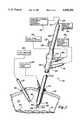
- FIG. 1is a block, schematic and perspective illustration showing the probe of the present invention in use in an abdominal cavity in association with various other equipment by which a minimally invasive surgical procedure is conducted.
- FIG. 2is an longitudinal cross-section of a handle of the probe shown in FIG. 1 at a proximal end of the probe.
- FIG. 3is an enlarged longitudinal cross-section of a tube of the probe shown in FIG. 1 at a distal end of the probe.
- FIG. 4is a perspective view of a nozzle and electrode assembly at the distal end of the probe shown in FIG. 3.
- FIG. 5is a cross-section view taken substantially in the plane of line 5--5 of FIG. 3.
- FIG. 6is a cross-section view taken substantially in the plane of line 6--6 of FIG. 3.
- FIG. 7is a cross-section view taken substantially in the plane of line 7--7 of FIG. 3.
- FIG. 8is an enlarged cross-sectional view of only the tube of the probe, similar to the views of the tube shown in FIGS. 5, 6 and 7.
- FIG. 9is an enlarged view of a portion of the handle of the probe shown in FIG. 2 illustrating details of a slider member.
- FIG. 10is a cross-sectional view taken substantially in the line of plane 10--10 in FIG. 9.
- FIG. 11is an enlarged view of a seal located within the handle of the probe shown in FIG. 2.
- a presently preferred embodiment and best mode presently known for practicing the present inventionis a probe 20 shown in FIG. 1.
- the probe 20is shown as it would typically be used in a minimally invasive surgical procedure in an abdominal or body cavity 22.
- the probe 20is inserted into the abdominal cavity through a cannula 24 which has previously been passed through the abdominal body or wall 26.
- An inflation pump 28forces pressurized and sterile gas, such as carbon dioxide, through the cannula 24 into the abdominal cavity 22.
- the abdominal wall 26expands away from the interior tissues and abdominal organs 30.
- a pressure sensor of the inflation pump 28controls the operation of the pump 28 to limit the amount of pressure within the abdominal cavity 22 and thereby limits the amount of expansion of the abdominal wall 26.
- a second cannula 34is also positioned in the abdominal wall 26, but the additional cannulas are not necessarily attached to the inflation pump 28.
- a video camera and light source device 36is connected to a wand-like device 38.
- the wand-like device 38is inserted into the abdominal cavity 22 through the cannula 34.
- the light source of the device 36illuminates the interior tissues and organs 30, and the video camera of the device 36 transmits video images to a video monitor 40. By viewing the interior organs 30, the surgeon is able to manipulate the probe 20 to achieve a desired surgical effect.
- the probe 20is connected to a gas assisted electro-fulguration device 42.
- the gas assisted electro-fulguration device 42is represented by the type of equipment described in U.S. Pat. No. 4,781,175 granted Nov. 1, 1988 for "Electrosurgical Conductive Gas Stream Technique of Achieving Improved Eschar for Coagulation" which is owned by the assignee hereof.
- Other U.S. patents and applications pertinent to gas assisted electro-fulgurationinclude U.S. Pat. No. 4,901,720 granted Feb. 20, 1990 for "Power Control for Beam-Type Electrosurgical Unit," U.S. Pat. No. 4,901,719 granted Feb. 20, 1990 for “Electrosurgical Conductive Gas Stream Equipment” and application Ser. No. 592,810, filed Oct. 4, 1990, for "Electrosurgical Handpiece Incorporating Blade and Conductive Gas Functionality.”
- gas assisted electro-fulgurationinvolves the delivery of a stream or jet of inert gas to the tissue at a surgical site while simultaneously transmitting electrical energy as arcs in ionized conductive pathways in the flowing gas jet.
- the interaction of the gas flow and the electrical arcsachieve a superior coagulative or hemostatic effect on bleeding tissue surfaces.
- Gas assisted electro-fulgurationis particularly useful and effective on aggressively bleeding surfaces because the gas is able to hold off and displace the blood from the surface of the tissue to allow the arcs of electrical energy carried in the gas to interact more thoroughly and effectively with the tissue.
- a more effective escharis created which is less susceptible to floating away due to a lack of adherence to the underlying tissue.
- the gas assisted electro-fulguration device 42 shown in FIG. 1is both the source of gas and the source of electrical energy, and both the gas and the electrical energy is supplied to the probe 20 at a gas electrosurgical port 44.
- the electro-fulguration effectis created at a front or distal end 46 of the probe 20
- the probe 20also offers the capability of accepting and utilizing a variety of auxiliary surgical instruments 48, such as a standard electrosurgical cutting and coagulation electrode, a laser fiber optic conduit for cutting and coagulation, an aqua dissection conduit, mechanical tools such as a knife or a biopsy collection device, and other types of surgical equipment.
- auxiliary surgical instrumentscan be inserted into the probe 20 from its rear or proximal end 50, or when the probe is removed from the cannula, from the distal end 46.
- the instrument 48may need to be connected to support equipment 52 by which to use the auxiliary surgical instrument 48.
- the support equipmentwill be a standard electrosurgical generator.
- the laser fiber optic conduitWhen a laser fiber optic conduit is used as the auxiliary surgical instrument with the probe 20, the laser fiber optic conduit will be connected to a laser beam device.
- the aqua dissection conduitWhen an aqua dissection conduit is used as the auxiliary surgical instrument, the aqua dissection conduit will be connected to a fluid pressure and flow generation device.
- a mechanical toolif a mechanical tool is used as the auxiliary surgical instrument, it may or may not be connected to support equipment, since manual control of many mechanical tools by the surgeon will operate them without additional support equipment.
- Another feature of the multifunctional probe 20is the capability to achieve irrigation, aspiration or evacuation within the abdominal cavity from the distal end 46 of the probe.
- the irrigation, aspiration or evacuationis achieved by fluid flow to or from the distal end 46 of the probe 20.
- a fluid flow control device 54is connected to a fluid flow port 56 of the probe 20 to achieve the irrigation, aspiration or evacuation.
- the surgeoncan grasp a handle 58 of the probe 20 and manipulate a connected tube 60 of the probe 20 to position the distal end 46 at the desired location to achieve the desired surgical effect on the tissue or organs 30.
- the probeis pivoted along with the cannula 24 at the point where both extend through the abdominal wall to move the distal end 46 to the desired location.
- the handle 58 and the tube 60are permanently connected together as a unitary structure by an adhesive or the like, and the handle 58 and the tube 60 are the two major elements of the probe 20.
- the handle 58 and the tube 60 and all of the components associated with these elements other than the metallic and elastomeric componentsare formed of plastic, to obtain a relatively inexpensive and disposable probe 20.
- the probe 20could also be formed of more long lasting and durable materials which are capable of repeated sterilizations, in order to allow the probe 20 to be used repeatedly before disposal.
- FIGS. 2 through 8More details concerning the gas assisted electro-fulguration aspects of the probe 20 are illustrated in FIGS. 2 through 8.
- a cylindrical conduit 62extends longitudinally completely through the tube 60 from the handle 58 to the distal end 46, as is understood from FIGS. 1, 2 and 3. With the tube 60 attached to the handle 58, the conduit 62 fits over a tubular sleeve 64 formed in the forward end of the handle 58.
- a divider or wall 66 within a hollow interior 68 of the handle 58defines a communication pathway 70 between the conduit 62 and the gas electrosurgical port 44.
- An electrical conductor 72extends through the conduit 62, the pathway 70 and out of the port 44 to the gas assisted electro-fulguration device 42. Electrical energy for electro-fulguration is supplied to the probe 20 over the conductor 72.
- a flexible tubing 74is connected from the port 44 to the gas assisted electrocoagulation device 42 by which gas for electro-fulguration is supplied to the probe 20 and the conduit 62.
- a nozzle and electrode assembly 76is retained in the conduit 62, as is shown in FIGS. 3 and 4.
- the conductor 72extends the length of the conduit 62 and is electrically connected by a connector 78 to the rear end of an elongated electrode 80 of the assembly 76.
- the rear end of the electrode 80is retained in the assembly 76 by a support structure 82. Due to the retention of the electrode 80 at the rear end thereof, the electrode projects forward in a cantilever supported manner.
- a rear portion 84 of the support structure 82is generally rectangularly shaped, and the rectangularly shaped portion 84 fits within the conduit 62 as is shown in FIGS. 4 and 5.
- a midsection 86 of the support structure 82is generally tubularly shaped, hollow and integral with the rectangularly shaped portion 84. At the forward end of the rectangular portion 84, slots 88 are formed transversely through the portion 84 to achieve a pathway into the hollow interior of the tubular midsection 86 and to expose the electrode 80, as is shown in FIG. 6.
- a receptacle portion 87extends forward from the midsection 86.
- a hollow sleeve 90is partially received within the receptacle portion 87, but the sleeve is of sufficient length to extend forward beyond the end of the receptacle portion 87.
- the midsection 86 and the sleeve 90surrounds the exposed forward projecting portion of the electrode 80. Both the sleeve 90 and the forward tip of the electrode 80 terminate at approximately the same location as shown, or alternatively, the electrode tip is slightly recessed within the sleeve 90.
- the support structure 82is formed of plastic
- the electrode 80is metallic such as tungsten
- the sleeve 90is ceramic.
- the electrode 80 and the sleeve 90are insert molded during the formation of the plastic support structure 82.
- the nozzle and electrode assembly 76is retained within the conduit 62 due to a friction fit, but an adhesive may also be employed to connect the assembly to the tube 60. If the sleeve 90 is not insert molded to the receptacle 87, an adhesive may be used to hold these elements together. In some circumstances, it may be possible to eliminate the receptacle 87 and rely on the retention of the support structure 82 and a portion of the sleeve within the conduit 62 (not shown) to hold these elements together.
- Two oppositely oriented D-shaped openings 92result on the opposite sides of the rectangularly shaped portion 84 when it is inserted in the conduit 62, as is shown in FIGS. 5 and 6. It is through these D-shaped openings 92 that gas is conducted from the conduit 62 into the slots 88 and into a cylindrical center opening 94 formed by the interiors of the hollow midsection 86 and the sleeve 90, as is shown in FIGS. 3 and 7.
- the cylindrical center opening 94is preferably concentric with the electrode 80.
- the center opening through the sleeve 90forms a nozzle for the gas to exit the assembly 76.
- the gasBefore exiting the nozzle, the gas surrounds the exposed electrode 80 and becomes ionized as it traverses through the nozzle as a result of the electrical potential applied on the electrode 80 from the conductor 72.
- the ionized gasconducts the electrical energy from the electrode 80 in arcs within the gas flowing from the nozzle to the tissue to achieve electro-fulguration.
- the tube 60also includes an instrument channel 100 which extends parallel to the conduit 62 along the length of the tube.
- the instrument channel 100communicates directly with the interior 68 of the handle 58 as is shown in FIG. 2.
- the channel 100extends continuously and longitudinally through the probe 20 from the distal end 46 at the tube 60 to the proximal end 50 at the handle 58. It is through this channel 100 that the various auxiliary surgical instruments are utilized in conjunction with the probe 20.
- the auxiliary surgical instrumentshould be generally elongated and have an exterior cylindrical shape to fit within the channel 100. As is shown in FIG. 8, a cross sectional view of the channel 100 reveals a crescent shaped configuration. An inner cylindrical wall 102 of the tube 60 is generally parallel to the outer cylindrical wall 104 of the tube 60. An inner partition 106 within the tube projects radially inward from both points at which the inner cylindrical wall 102 terminates. The partition 106 separates the conduit 62 from the channel 100 along with the length of the tube 60.
- the partition 106has a cylindrically curved support surface 108 which faces radially outward. The inner most location of concavity of the support surface 108 is at the central axis 110 of the tube 60. The curvature of the support surface 108 is defined by an equal length radius from a point 112 which is midway between the axis 110 of the tube and the inner cylindrical wall 102. The point 112 is located at the longitudinal axis of the auxiliary surgical instrument.
- a longitudinal auxiliary surgical instrumenthaving a diameter slightly less than the distance between the axis 110 and the wall 102 will fit within the instrument channel 100 and be supported by and retained in position when it rests on the support surface 108 and the interior surface 102, as is shown in FIGS. 3, 5, 6 and 7.
- the longitudinal axis of the instrument channel 100becomes the same as the longitudinal axis of the auxiliary surgical instrument, and both axes are located at the point 112. Because the support surface 108 curves radially outward from the axis 110 of the tube 60 and toward the interior cylindrical wall 102, the cylindrically shaped surgical instrument will be prevented from moving transversely within the instrument channel 100.
- the support surface 108 and the interior surface 102are one example of means for supporting the auxiliary surgical instrument in the channel 100, however other types and configurations of support means, either integral with the tube 60 or separate components, may be used as alternatives.
- FIGS. 1, 2, 3, 5 and 6an exemplary standard electrosurgical coagulation and cutting electrode 120 is illustrated in FIGS. 1, 2, 3, 5 and 6 as the auxiliary surgical instrument 48.
- the electrosurgical electrode 120is formed from a hollow metallic tube 122 upon which an exterior layer of insulating material 124 such as heat shrink tubing is connected.
- the tube 122is preferably formed from stainless steel or aluminum.
- a metallic terminal end 126(FIG. 1) is mechanically and electrically connected to the tube 122.
- the terminal end 126allows an electrical conductor connected to a conventional electrosurgical generator to be connected to the electrode 120 as the support equipment 52 (FIG. 1).
- a metallic operating tip 128is mechanically and electrically connected to the tube 122.
- the tip 128may be of a variety of configurations adapted for the particular surgical procedure which the surgeon desires to accomplish. So long as the tip 128 extends no further transversely outward at any location than the exterior surface of the electrode 120, the electrode 120 can be inserted and removed from the channel 100 from the proximal end of the probe 20, while the probe is in place in the abdominal cavity 22 (FIG. 1). If the operating tip 128 is larger than the exterior surface of the electrode 120, the auxiliary surgical instrument must be inserted in the instrument channel 100 before the probe is inserted in the cannula 24 (FIG. 1).
- the probe 20includes a slider member 130, which is shown in FIGS. 2, 9 and 10.
- the slider member 130is movably retained within the interior 68 of the handle 58, to allow longitudinal movement along the instrument channel 100.
- the auxiliary surgical instrument 48extends through a slot 134 in the slider member 130 and a lock roller member 132 applies frictional retaining force by which to selectively retain the slider member to the auxiliary surgical instrument 48.
- the slot 134 of the slider member 130 in which the auxiliary surgical instrument is retainedhas a U-shaped configuration which extends continuously longitudinally along and forms a part of the instrument channel 100.
- An inner cylindrical surface of the U-shaped slot 134is of uniform radius from the instrument axis (FIG. 10).
- the straight leg portions of the U-shaped slot 134integrally connect to a base portion 136 of the slider member 130.
- the base portion 136extends the length of the slider member 130.
- a transversely center point on the bottom surface of the base portion 136is located at approximately the same distance from the instrument axis 112 as the curved surface of the U-shaped slot 134, thus allowing the auxiliary surgical instrument to closely fit within the U-shaped slot 134.
- a pair of wing portions 138extend upward from opposite transverse sides of the base portion 136.
- the wing portions 138each have an opening 140 formed therein for receiving a rotational axle 142 of the lock roller 132.
- the axle 142 of the lock roller 132is snapped into the openings 140 by slightly spreading the wing portions 138 and sliding the lock roller 132 between them until the axle 142 enters the openings 140.
- the resiliency of the wing portionsreturns them to the original position to hold the lock roller in position.
- the axlemay not be made integral with the lock roller, but instead, a hole (not shown) may be formed through the lock roller at the location of the axle.
- a brass or other type of pin(also not shown) will be inserted through this hole and the openings 140 to hold the lock roller in a pivotably connected condition to the wing portions.
- Use of the separate pinavoids the necessity to obtain sufficient resilience from the wing portions to allow them the accept the integral axle as shown.
- the lock roller 132includes an upper surface 144 which extends above the wing portions 138.
- the upper surface 144has transverse slots or other types of ridges or indentions formed therein by which the surgeon can adequately frictionally engage the surface 144 and rotate the lock roller 132 about the axle 142.
- a cam surface 146is eccentrically positioned relative to the axle 142 at the lower end of the lock roller 132.
- the cam surface 146applies lateral force on the auxiliary surgical instrument 48 located within the U-shaped slot 134 of the slider member 130.
- a flat surface 148 of the cam surface 146contacts the outer exterior of the auxiliary surgical instrument 48 and causes the lock roller 132 to be retained in position.
- the amount of eccentric movement of the cam surface 146 and the flat surface 148is sufficient to frictionally retain the auxiliary surgical instrument in the U-shaped slot 134 so that the instrument 48 moves in conjunction with the slider member 130.
- the extension and retraction of the operating tip of the auxiliary surgical instrument at the distal end of the probeis achieved by moving the slider member 130 forward and backward.
- an opening 150is formed in the housing 58 to allow the lock roller 132 and wing portions 138 to move forward and rearwardly on the exterior of the handle 58.
- the lock roller 132is one of many alternative examples of a retaining means for selectively retaining the auxiliary surgical instrument to the slider member.
- a retaining meansfor selectively retaining the auxiliary surgical instrument to the slider member.
- Virtually any type of controllable retaining device capable of achieving a sufficient frictional engagement with the auxiliary surgical instrument to cause it to move with the slider memberwill suffice as an alternative to the lock roller 132.
- the forward lower end of the U-shaped slot 134has formed therein a notch 152 which is adapted to receive a ridge 154 of a resilient tang 156 located within the interior 68 of the handle 58, as is shown in FIGS. 2 and 9.
- the resilient tang 156deflects toward and away from the slider member and transversely with respect to the instrument channel 100, to allow the ridge 154 to snap within the notch 152 when the slider member 130 is moved to the forward position within the opening 150.
- This featureallows the surgeon to fix the desired amount of extension of the auxiliary surgical instrument from the distal end 46 of the probe.
- the lock roller 132By releasing the lock roller 132, adjusting the position of the auxiliary surgical instrument by grasping it from the rear end of the housing 58, and then rotating the lock roller 132 back into the retaining position, the position of the auxiliary surgical instrument in the probe 20 is changed.
- the surgeoncan extend and retract the auxiliary surgical instrument by longitudinal movement of the slider member 130, provided that the slider member is not moved forward to the retained position.
- cam surface 146 and the flat surface 148it is preferred to arrange the cam surface 146 and the flat surface 148 to achieve retention between the slider member and the auxiliary surgical instrument 48 due to clockwise movement of the lock roller as shown in FIGS. 2 and 9.
- Clockwise movement of the lock rollerresults from finger force which has a component tending to move the slider member rearward. Since a rearward component of finger force is required to overcome the force of the tang 156 to move the slider member rearward from the forwardmost position, the lock roller will not rotate to accidentally release the auxiliary surgical instrument when the slider member is moved rearward from the forward most position.
- the probeIn order to irrigate, aspirate and evacuate fluid (gas or liquid) from within the abdominal cavity and at the surgical site, the probe includes at least one passageway extending through the tube 60 to the distal end 46.
- the embodiment of the probe 20 shownactually includes two passageways 160 as is shown in FIGS. 5, 6 and 7.
- the passageways 60extend through the tube 160 on each side of the auxiliary surgical instrument 48, represented by the electrode 120, and communicate with a chamber 162 formed in the interior 68 of the handle 58, as shown in FIG. 2.
- the rear end of the chamber 162is closed by a seal 164.
- the divider 66separates the chamber 162 from the pathway 70.
- the chamber 162communicates with the fluid flow port 56.
- a standard luer fitting 166is connected to the end of the port 56, and a hose or other tubular conduit connects the fluid flow control device 54 (FIG. 1) to the probe 20 at the luer fitting.
- the seal 164is one example of a sealing means for providing a fluid seal between the auxiliary surgical instrument 48 and the interior 68 of the handle 58. Consequently, the fluid within the abdominal cavity, whether it be liquid or gas, is confined within the interior chamber 162 for communication into and out of the fluid flow port 56. The seal 164 prevents the fluid from entering the other portions of the handle 58 and interfering with the movement of the slider member 130, for example.
- the seal 164is illustrated in FIG. 11 to include an outer relatively thick edge 168 from which there extends inwardly a relatively thin membrane 170.
- the edge 168fits within a retention receptacle 172 formed within the interior of the handle 58, as is shown in FIG. 2.
- a plastic ring 169contacts the edge 168 and expands the edge 168 outward to hold the seal in position in the receptacle 172.
- a circular opening 174is formed for the purpose of receiving the generally circular exterior configuration of the auxiliary surgical instruments 48.
- the opening 174is located at the axial center 112 of the auxiliary surgical instrument and the channel 100.
- the seal 164is preferably formed of a resilient elastomeric material, and the deflection, flexibility and resilience of the membrane 170 achieves the fluid tight seal against the exterior surface of the auxiliary surgical instrument, as shown in FIG. 2.
- the membrane 170thus resists the passage of the fluid into or out of the interior chamber 162 from around the auxiliary surgical instrument, and confines all fluid flow through the port 56.
- the ring 169is preferably formed of more rigid plastic material.
- Other types of sealing meanswhich provide the equivalent functionality for confining the fluid in the interior chamber 162 might serve as alternatives to the seal 168 described above.
- a pressure relief valve 180connected in fluid communication with the interior chamber 162.
- the pressure relief valve 180is retained in a receptacle 182 formed in the handle 58, and is operative to vent pressurized fluid within the interior chamber 162 to the exterior of the handle upon the pressure of the fluid exceeding a predetermined level.
- the pressure relief valve 180is particularly useful in preventing over inflation of the abdominal cavity during gas assisted electro-fulguration.
- the gas added to the abdominal cavity during electro-fulgurationcontributes to the pressure in the abdominal cavity.
- the back pressure sensor of the inflation pump(28, FIG. 1) may terminate the delivery of gas from the inflation pump to the abdominal cavity, the gas from the gas assisted electro-fulguration may continue to expand the abdominal wall.
- the limited venting from the incision around the cannulais typically not sufficient to prevent over-pressurization during gas assisted electro-coagulation, but the pressure relief valve 180 will relieve this additional pressure once it exceeds the release point of the pressure relief valve 180. Since the interior chamber 162 communicates with the abdominal cavity 22 (FIG. 1) through the passageways 160 (FIGS. 5-7), the pressure relief valve 180 acts as an auxiliary or back up for the proper functionality of the back pressure sensor associated with the inflation pump 28 (FIG. 1). The incorporation of the pressure relief valve 180 in the probe 20 thus increases the measure of safety against the accidental over pressurization of the abdominal cavity during a minimally invasive surgery.
- the general nature of pressure relief valvesis well known.
- the longitudinal arrangement of the instrument channel in the manner describedprovides the substantial advantage of the surgeon not having to withdraw the probe from the cannula to exchange auxiliary surgical instruments which have operating tips that do not exceed the outside dimensions of the instrument.
- auxiliary surgical instrumentswhich do have larger operating tips can be inserted from the distal end of the probe prior to insertion in the cannula.
- one of the substantial advantages offered by the probe 20is the capability of instantly obtaining gas assisted electro-fulguration when necessary.
- the availability of gas assisted electro-fulgurationgreatly reduces the risk of immediate and serious bleeding before the surgeon is able to control it by other conventional means.
- a sufficient amount of bleedingcan greatly obstruct the surgical site and inhibit the further progress of the procedure, particularly if it becomes necessary to remove one probe, insert another probe to attempt to control the bleeding, remove that probe, and insert yet another probe to evacuate the blood which accumulated before the bleeding was controlled.
Landscapes
- Health & Medical Sciences (AREA)
- Surgery (AREA)
- Engineering & Computer Science (AREA)
- Life Sciences & Earth Sciences (AREA)
- Medical Informatics (AREA)
- Molecular Biology (AREA)
- Nuclear Medicine, Radiotherapy & Molecular Imaging (AREA)
- Plasma & Fusion (AREA)
- Biomedical Technology (AREA)
- Heart & Thoracic Surgery (AREA)
- Physics & Mathematics (AREA)
- Otolaryngology (AREA)
- Animal Behavior & Ethology (AREA)
- General Health & Medical Sciences (AREA)
- Public Health (AREA)
- Veterinary Medicine (AREA)
- Surgical Instruments (AREA)
- Ultra Sonic Daignosis Equipment (AREA)
- Medicines Containing Antibodies Or Antigens For Use As Internal Diagnostic Agents (AREA)
- Endoscopes (AREA)
Abstract
Description
Claims (38)
Priority Applications (6)
| Application Number | Priority Date | Filing Date | Title |
|---|---|---|---|
| US07/779,101US5449356A (en) | 1991-10-18 | 1991-10-18 | Multifunctional probe for minimally invasive surgery |
| EP19920921703EP0608318A4 (en) | 1991-10-18 | 1992-10-13 | Multifunctional probe for minimally invasive surgery. |
| PCT/US1992/008706WO1993007821A1 (en) | 1991-10-18 | 1992-10-13 | Multifunctional probe for minimally invasive surgery |
| AU28098/92AAU2809892A (en) | 1991-10-18 | 1992-10-13 | Multifunctional probe for minimally invasive surgery |
| JP5507757AJPH07500041A (en) | 1991-10-18 | 1992-10-13 | Multifunctional probe for minimally invasive surgery |
| CA002121231ACA2121231C (en) | 1991-10-18 | 1992-10-13 | Multifunctional probe for minimally invasive surgery |
Applications Claiming Priority (1)
| Application Number | Priority Date | Filing Date | Title |
|---|---|---|---|
| US07/779,101US5449356A (en) | 1991-10-18 | 1991-10-18 | Multifunctional probe for minimally invasive surgery |
Publications (1)
| Publication Number | Publication Date |
|---|---|
| US5449356Atrue US5449356A (en) | 1995-09-12 |
Family
ID=25115331
Family Applications (1)
| Application Number | Title | Priority Date | Filing Date |
|---|---|---|---|
| US07/779,101Expired - LifetimeUS5449356A (en) | 1991-10-18 | 1991-10-18 | Multifunctional probe for minimally invasive surgery |
Country Status (6)
| Country | Link |
|---|---|
| US (1) | US5449356A (en) |
| EP (1) | EP0608318A4 (en) |
| JP (1) | JPH07500041A (en) |
| AU (1) | AU2809892A (en) |
| CA (1) | CA2121231C (en) |
| WO (1) | WO1993007821A1 (en) |
Cited By (168)
| Publication number | Priority date | Publication date | Assignee | Title |
|---|---|---|---|---|
| US5662647A (en)* | 1991-07-22 | 1997-09-02 | Transamerican Technologies International | Electrode assembly for electrosurgical instrument |
| US5685877A (en)* | 1995-09-19 | 1997-11-11 | Anthony Pagedas | Mutiple tool laparoscopic surgical instrument |
| WO1999003406A1 (en)* | 1997-07-14 | 1999-01-28 | Erbe Elektromedizin Gmbh | Preparation instruments |
| US5910139A (en)* | 1996-08-29 | 1999-06-08 | Storz Instrument Co. | Numeric keypad simulated on touchscreen |
| US5993447A (en)* | 1996-08-16 | 1999-11-30 | United States Surgical | Apparatus for thermal treatment of tissue |
| US5997528A (en)* | 1996-08-29 | 1999-12-07 | Bausch & Lomb Surgical, Inc. | Surgical system providing automatic reconfiguration |
| US6055458A (en)* | 1997-08-28 | 2000-04-25 | Bausch & Lomb Surgical, Inc. | Modes/surgical functions |
| US6086576A (en)* | 1996-08-29 | 2000-07-11 | Bausch & Lomb Surgical, Inc. | Automatically switching the termination of a communications bus |
| US6117126A (en)* | 1996-08-29 | 2000-09-12 | Bausch & Lomb Surgical, Inc. | Surgical module with independent microprocessor-based communication |
| US6197024B1 (en) | 1999-09-22 | 2001-03-06 | Scott Keith Sullivan | Adjustable electrocautery surgical apparatus |
| US6251113B1 (en) | 1996-08-29 | 2001-06-26 | Bausch & Lomb Surgical, Inc. | Ophthalmic microsurgical system employing surgical module employing flash EEPROM and reprogrammable modules |
| US6293945B1 (en) | 2000-03-06 | 2001-09-25 | Everest Medical Corporation | Electrosurgical instrument with suction capability |
| US6293946B1 (en) | 1999-08-27 | 2001-09-25 | Link Technology, Inc. | Non-stick electrosurgical forceps |
| EP1267700A4 (en)* | 2000-03-24 | 2003-04-02 | George L Scott Iii | Laparoscopic instrument system for stone removal |
| US6679880B2 (en)* | 2001-07-23 | 2004-01-20 | Par Value International Limited | Electrosurgical hand piece |
| US20040034339A1 (en)* | 2002-08-16 | 2004-02-19 | The Regents Of The University Of California | Device for improved visualization of operative sites during surgery |
| US20040116832A1 (en)* | 2002-06-21 | 2004-06-17 | Curative Medical Devices Gmbh | Catheter arrangement |
| US20040230190A1 (en)* | 1998-08-11 | 2004-11-18 | Arthrocare Corporation | Electrosurgical apparatus and methods for tissue treatment and removal |
| US20050085695A1 (en)* | 2003-10-16 | 2005-04-21 | Cemal Shener | Endoscopic device |
| US20050199250A1 (en)* | 2004-03-11 | 2005-09-15 | Green John M.Ii | System for determining a position of a point on an object |
| US20050234298A1 (en)* | 2004-01-29 | 2005-10-20 | Cannuflow Incorporated | Atraumatic arthroscopic instrument sheath |
| US20060047185A1 (en)* | 2004-08-27 | 2006-03-02 | Cemal Shener | Tissue resecting system |
| US20070078302A1 (en)* | 2005-08-05 | 2007-04-05 | Ortiz Mark S | Method and apparatus for sealing a gastric opening |
| US20070149966A1 (en)* | 1995-11-22 | 2007-06-28 | Arthrocare Corporation | Electrosurgical Apparatus and Methods for Treatment and Removal of Tissue |
| US20070149970A1 (en)* | 2003-10-30 | 2007-06-28 | Erbe Elektromedin Gmbh | Apparatus for coagulating tissue |
| US7249602B1 (en)* | 1997-09-04 | 2007-07-31 | Smith & Nephew, Inc. | Surgical endoscopic cutting device and method for its use |
| US20070213704A1 (en)* | 1999-05-24 | 2007-09-13 | Arqos Surgical Inc. | Electrical discharge devices and techniques for medical procedures |
| US20070282323A1 (en)* | 2006-05-30 | 2007-12-06 | Arthrocare Corporation | Hard tissue ablation system |
| US20080006174A1 (en)* | 1997-09-30 | 2008-01-10 | Richard Sapienza | Environmentally benign anti-icing or deicing fluids |
| US20080058801A1 (en)* | 2006-09-01 | 2008-03-06 | Taylor Kenneth D | Adapter and method for converting gas-enhanced electrosurgical coagulation instrument for cutting |
| US20090043165A1 (en)* | 2004-01-29 | 2009-02-12 | Cannuflow Incorporated | Atraumatic Arthroscopic Instrument Sheath |
| US20090062791A1 (en)* | 2007-08-30 | 2009-03-05 | Lee Alan R | Integrated smoke evacuation electrosurgical pencil and method |
| US20090177141A1 (en)* | 2006-02-03 | 2009-07-09 | Cannuflow, Inc. | Anti-Extravasation Sheath |
| US20090216227A1 (en)* | 2006-01-06 | 2009-08-27 | Arthrocare Corporation | Electrosurgical method and system for treating foot ulcer |
| US20090278078A1 (en)* | 1997-09-30 | 2009-11-12 | Richard Sapienza | Environmentally benign anti-icing or deicing fluids |
| US20090314983A1 (en)* | 2003-01-13 | 2009-12-24 | Richard Sapienza | Environmentally benign anti-icing or deicing fluids |
| US20100042097A1 (en)* | 2008-08-18 | 2010-02-18 | Encision, Inc. | Enhanced control systems including flexible shielding and support systems for electrosurgical applications |
| US7862560B2 (en) | 2007-03-23 | 2011-01-04 | Arthrocare Corporation | Ablation apparatus having reduced nerve stimulation and related methods |
| US20110230904A1 (en)* | 2001-10-26 | 2011-09-22 | Smith & Nephew, Inc. | Reciprocating rotary arthroscopic surgical instrument |
| USD658760S1 (en) | 2010-10-15 | 2012-05-01 | Arthrocare Corporation | Wound care electrosurgical wand |
| WO2012055816A1 (en)* | 2010-10-26 | 2012-05-03 | Erbe Elektromedizin Gmbh | Hemostasis instrument |
| US8192424B2 (en) | 2007-01-05 | 2012-06-05 | Arthrocare Corporation | Electrosurgical system with suction control apparatus, system and method |
| US8222822B2 (en) | 2009-10-27 | 2012-07-17 | Tyco Healthcare Group Lp | Inductively-coupled plasma device |
| US8257350B2 (en) | 2009-06-17 | 2012-09-04 | Arthrocare Corporation | Method and system of an electrosurgical controller with wave-shaping |
| US8372067B2 (en) | 2009-12-09 | 2013-02-12 | Arthrocare Corporation | Electrosurgery irrigation primer systems and methods |
| US8568405B2 (en) | 2010-10-15 | 2013-10-29 | Arthrocare Corporation | Electrosurgical wand and related method and system |
| US8575843B2 (en) | 2008-05-30 | 2013-11-05 | Colorado State University Research Foundation | System, method and apparatus for generating plasma |
| US8574187B2 (en) | 2009-03-09 | 2013-11-05 | Arthrocare Corporation | System and method of an electrosurgical controller with output RF energy control |
| US8685018B2 (en) | 2010-10-15 | 2014-04-01 | Arthrocare Corporation | Electrosurgical wand and related method and system |
| US20140139658A1 (en)* | 2012-11-20 | 2014-05-22 | General Electric Company | Remote visual inspection system and method |
| US8747399B2 (en) | 2010-04-06 | 2014-06-10 | Arthrocare Corporation | Method and system of reduction of low frequency muscle stimulation during electrosurgical procedures |
| US8758336B2 (en) | 2004-08-17 | 2014-06-24 | Encision, Inc. | System and method for monitoring electrosurgical systems |
| US8876746B2 (en) | 2006-01-06 | 2014-11-04 | Arthrocare Corporation | Electrosurgical system and method for treating chronic wound tissue |
| US20140364870A1 (en)* | 2013-06-11 | 2014-12-11 | Auris Surgical Robotics, Inc. | Method, apparatus, and a system for robotic assisted cataract surgery |
| US8994270B2 (en) | 2008-05-30 | 2015-03-31 | Colorado State University Research Foundation | System and methods for plasma application |
| WO2015031852A3 (en)* | 2013-08-31 | 2015-04-30 | Andrew Cooper | Double lumen arthroscopy port |
| US9028656B2 (en) | 2008-05-30 | 2015-05-12 | Colorado State University Research Foundation | Liquid-gas interface plasma device |
| US9060765B2 (en) | 2010-11-08 | 2015-06-23 | Bovie Medical Corporation | Electrosurgical apparatus with retractable blade |
| US9131597B2 (en) | 2011-02-02 | 2015-09-08 | Arthrocare Corporation | Electrosurgical system and method for treating hard body tissue |
| US9144453B2 (en) | 2010-11-08 | 2015-09-29 | Bovie Medical Corporation | Multi-mode electrosurgical apparatus |
| US9155454B2 (en) | 2010-09-28 | 2015-10-13 | Smith & Nephew, Inc. | Hysteroscopic system |
| US9204918B2 (en) | 2011-09-28 | 2015-12-08 | RELIGN Corporation | Medical ablation system and method of use |
| US9247983B2 (en) | 2011-11-14 | 2016-02-02 | Arqos Surgical, Inc. | Medical instrument and method of use |
| US9272359B2 (en) | 2008-05-30 | 2016-03-01 | Colorado State University Research Foundation | Liquid-gas interface plasma device |
| US9277954B2 (en) | 2011-03-21 | 2016-03-08 | Arqos Surgical, Inc. | Medical ablation system and method of use |
| US9288886B2 (en) | 2008-05-30 | 2016-03-15 | Colorado State University Research Foundation | Plasma-based chemical source device and method of use thereof |
| US9326810B2 (en) | 2010-11-08 | 2016-05-03 | Bovie Medical Corporation | Multi-button electrosurgical apparatus |
| US9358063B2 (en) | 2008-02-14 | 2016-06-07 | Arthrocare Corporation | Ablation performance indicator for electrosurgical devices |
| CN106028991A (en)* | 2014-01-23 | 2016-10-12 | 兰德股份公司 | Plasma device |
| US9510889B2 (en) | 2003-10-30 | 2016-12-06 | Erbe Elektromedizin Gmbh | Apparatus for coagulating tissue |
| US9532826B2 (en) | 2013-03-06 | 2017-01-03 | Covidien Lp | System and method for sinus surgery |
| US9555145B2 (en) | 2013-03-13 | 2017-01-31 | Covidien Lp | System and method for biofilm remediation |
| US9585675B1 (en) | 2015-10-23 | 2017-03-07 | RELIGN Corporation | Arthroscopic devices and methods |
| US9603656B1 (en) | 2015-10-23 | 2017-03-28 | RELIGN Corporation | Arthroscopic devices and methods |
| US9681913B2 (en) | 2015-04-21 | 2017-06-20 | RELIGN Corporation | Arthroscopic devices and methods |
| US9693818B2 (en) | 2013-03-07 | 2017-07-04 | Arthrocare Corporation | Methods and systems related to electrosurgical wands |
| US9713489B2 (en) | 2013-03-07 | 2017-07-25 | Arthrocare Corporation | Electrosurgical methods and systems |
| US9763724B2 (en) | 2012-07-02 | 2017-09-19 | Bovie Medical Corporation | Systems and methods of discriminating between argon and helium gases for enhanced safety of medical devices |
| US9770285B2 (en) | 2010-11-08 | 2017-09-26 | Bovie Medical Corporation | System and method for identifying and controlling an electrosurgical apparatus |
| US9801678B2 (en) | 2013-03-13 | 2017-10-31 | Arthrocare Corporation | Method and system of controlling conductive fluid flow during an electrosurgical procedure |
| US20170340376A1 (en)* | 2016-05-25 | 2017-11-30 | Amit Trivedi | Pressure Relief System for Use with Gas-Assisted Minimally Invasive Surgical Devices |
| US9833281B2 (en) | 2008-08-18 | 2017-12-05 | Encision Inc. | Enhanced control systems including flexible shielding and support systems for electrosurgical applications |
| US10004556B2 (en) | 2013-05-10 | 2018-06-26 | Corinth MedTech, Inc. | Tissue resecting devices and methods |
| US10022140B2 (en) | 2016-02-04 | 2018-07-17 | RELIGN Corporation | Arthroscopic devices and methods |
| US10299819B2 (en) | 2016-07-28 | 2019-05-28 | Covidien Lp | Reciprocating rotary surgical cutting device and system for tissue resecting, and method for its use |
| US10299803B2 (en) | 2016-08-04 | 2019-05-28 | Covidien Lp | Self-aligning drive coupler |
| US10350390B2 (en) | 2011-01-20 | 2019-07-16 | Auris Health, Inc. | System and method for endoluminal and translumenal therapy |
| US10595889B2 (en) | 2016-04-11 | 2020-03-24 | RELIGN Corporation | Arthroscopic devices and methods |
| US10631889B2 (en) | 2014-12-16 | 2020-04-28 | Covidien Lp | Surgical device with incorporated tissue extraction |
| US10639114B2 (en) | 2018-08-17 | 2020-05-05 | Auris Health, Inc. | Bipolar medical instrument |
| US10639109B2 (en) | 2015-04-01 | 2020-05-05 | Auris Health, Inc. | Microsurgical tool for robotic applications |
| US10639108B2 (en) | 2015-10-30 | 2020-05-05 | Auris Health, Inc. | Process for percutaneous operations |
| US10743751B2 (en) | 2017-04-07 | 2020-08-18 | Auris Health, Inc. | Superelastic medical instrument |
| US10750931B2 (en) | 2015-05-26 | 2020-08-25 | Covidien Lp | Systems and methods for generating a fluid bearing for an operative procedure |
| US10751140B2 (en) | 2018-06-07 | 2020-08-25 | Auris Health, Inc. | Robotic medical systems with high force instruments |
| US10772652B2 (en) | 2015-01-28 | 2020-09-15 | Covidien Lp | Tissue resection system |
| US10772654B2 (en) | 2017-03-02 | 2020-09-15 | Covidien Lp | Fluid-driven tissue resecting instruments, systems, and methods |
| US10792466B2 (en) | 2017-03-28 | 2020-10-06 | Auris Health, Inc. | Shaft actuating handle |
| US10799264B2 (en) | 2015-06-18 | 2020-10-13 | Covidien Lp | Surgical instrument with suction control |
| US10804769B2 (en) | 2015-06-17 | 2020-10-13 | Covidien Lp | Surgical instrument with phase change cooling |
| US10828118B2 (en) | 2018-08-15 | 2020-11-10 | Auris Health, Inc. | Medical instruments for tissue cauterization |
| US10842350B2 (en) | 2015-06-17 | 2020-11-24 | Covidien Lp | Endoscopic device with drip flange and methods of use thereof for an operative procedure |
| US10869684B2 (en) | 2018-02-13 | 2020-12-22 | Covidien Lp | Powered tissue resecting device |
| US10898218B2 (en) | 2019-02-25 | 2021-01-26 | Covidien Lp | Tissue resecting device including a motor cooling assembly |
| US10945752B2 (en) | 2019-03-20 | 2021-03-16 | Covidien Lp | Tissue resecting instrument including a rotation lock feature |
| US10959792B1 (en) | 2019-09-26 | 2021-03-30 | Auris Health, Inc. | Systems and methods for collision detection and avoidance |
| US10980669B2 (en) | 2013-01-18 | 2021-04-20 | Auris Health, Inc. | Method, apparatus and system for a water jet |
| US10987174B2 (en) | 2017-04-07 | 2021-04-27 | Auris Health, Inc. | Patient introducer alignment |
| US20210128189A1 (en)* | 2012-02-29 | 2021-05-06 | Procept Biorobotics Corporation | Automated image-guided tissue resection and treatment |
| CN112826583A (en)* | 2019-11-22 | 2021-05-25 | 厄比电子医学有限责任公司 | Probe head |
| US11033330B2 (en) | 2008-03-06 | 2021-06-15 | Aquabeam, Llc | Tissue ablation and cautery with optical energy carried in fluid stream |
| US11065147B2 (en) | 2018-10-18 | 2021-07-20 | Covidien Lp | Devices, systems, and methods for pre-heating fluid to be introduced into a patient during a surgical procedure |
| US11065023B2 (en) | 2017-03-17 | 2021-07-20 | RELIGN Corporation | Arthroscopic devices and methods |
| US11083481B2 (en) | 2019-02-22 | 2021-08-10 | Covidien Lp | Tissue resecting instrument including an outflow control seal |
| US11109928B2 (en) | 2019-06-28 | 2021-09-07 | Auris Health, Inc. | Medical instruments including wrists with hybrid redirect surfaces |
| US11135032B2 (en) | 2016-04-04 | 2021-10-05 | Gyrus Acmi, Inc. | Electrosurgical illuminating instrument |
| US11154318B2 (en) | 2019-02-22 | 2021-10-26 | Covidien Lp | Tissue resecting instrument including an outflow control seal |
| US11172953B2 (en) | 2016-04-11 | 2021-11-16 | RELIGN Corporation | Arthroscopic devices and methods |
| US11179172B2 (en) | 2019-12-05 | 2021-11-23 | Covidien Lp | Tissue resecting instrument |
| US11197710B2 (en) | 2018-10-26 | 2021-12-14 | Covidien Lp | Tissue resecting device including a blade lock and release mechanism |
| US11207119B2 (en) | 2016-03-11 | 2021-12-28 | RELIGN Corporation | Arthroscopic devices and methods |
| US11272973B2 (en) | 2015-01-28 | 2022-03-15 | Apyx Medical Corporation | Cold plasma electrosurgical apparatus with bent tip applicator |
| US11317947B2 (en) | 2020-02-18 | 2022-05-03 | Covidien Lp | Tissue resecting instrument |
| US11350964B2 (en) | 2007-01-02 | 2022-06-07 | Aquabeam, Llc | Minimally invasive treatment device for tissue resection |
| US11357586B2 (en) | 2020-06-30 | 2022-06-14 | Auris Health, Inc. | Systems and methods for saturated robotic movement |
| US11369386B2 (en) | 2019-06-27 | 2022-06-28 | Auris Health, Inc. | Systems and methods for a medical clip applier |
| US11376032B2 (en) | 2019-12-05 | 2022-07-05 | Covidien Lp | Tissue resecting instrument |
| US11382650B2 (en) | 2015-10-30 | 2022-07-12 | Auris Health, Inc. | Object capture with a basket |
| US11399905B2 (en) | 2018-06-28 | 2022-08-02 | Auris Health, Inc. | Medical systems incorporating pulley sharing |
| WO2022173740A1 (en)* | 2021-02-09 | 2022-08-18 | Baxter International Inc. | Peritoneal trocar apparatus and system |
| US11426231B2 (en) | 2017-01-11 | 2022-08-30 | RELIGN Corporation | Arthroscopic devices and methods |
| US11439419B2 (en) | 2019-12-31 | 2022-09-13 | Auris Health, Inc. | Advanced basket drive mode |
| US11452806B2 (en) | 2019-10-04 | 2022-09-27 | Covidien Lp | Outflow collection vessels, systems, and components thereof for hysteroscopic surgical procedures |
| US11534248B2 (en) | 2019-03-25 | 2022-12-27 | Auris Health, Inc. | Systems and methods for medical stapling |
| US11547815B2 (en) | 2018-05-30 | 2023-01-10 | Covidien Lp | Systems and methods for measuring and controlling pressure within an internal body cavity |
| US11547782B2 (en) | 2020-01-31 | 2023-01-10 | Covidien Lp | Fluid collecting sheaths for endoscopic devices and systems |
| US11553977B2 (en) | 2019-05-29 | 2023-01-17 | Covidien Lp | Hysteroscopy systems and methods for managing patient fluid |
| US11571229B2 (en) | 2015-10-30 | 2023-02-07 | Auris Health, Inc. | Basket apparatus |
| US11571233B2 (en) | 2020-11-19 | 2023-02-07 | Covidien Lp | Tissue removal handpiece with integrated suction |
| US11576738B2 (en) | 2018-10-08 | 2023-02-14 | Auris Health, Inc. | Systems and instruments for tissue sealing |
| US11589913B2 (en) | 2019-01-25 | 2023-02-28 | Auris Health, Inc. | Vessel sealer with heating and cooling capabilities |
| US11596429B2 (en) | 2020-04-20 | 2023-03-07 | Covidien Lp | Tissue resecting instrument |
| US11602390B2 (en) | 2017-01-30 | 2023-03-14 | Apyx Medical Corporation | Electrosurgical apparatus with flexible shaft |
| US11642242B2 (en) | 2013-08-13 | 2023-05-09 | Auris Health, Inc. | Method and apparatus for light energy assisted surgery |
| US11737777B2 (en) | 2020-02-05 | 2023-08-29 | Covidien Lp | Tissue resecting instruments |
| US11737835B2 (en) | 2019-10-29 | 2023-08-29 | Auris Health, Inc. | Braid-reinforced insulation sheath |
| US11737845B2 (en) | 2019-09-30 | 2023-08-29 | Auris Inc. | Medical instrument with a capstan |
| US11839969B2 (en) | 2020-06-29 | 2023-12-12 | Auris Health, Inc. | Systems and methods for detecting contact between a link and an external object |
| US11864735B2 (en) | 2016-05-26 | 2024-01-09 | Covidien Lp | Continuous flow endoscope |
| US11864849B2 (en) | 2018-09-26 | 2024-01-09 | Auris Health, Inc. | Systems and instruments for suction and irrigation |
| US11877788B2 (en) | 2017-05-30 | 2024-01-23 | Apyx Medical Corporation | Electrosurgical apparatus with robotic tip |
| US11883058B2 (en) | 2019-03-26 | 2024-01-30 | Covidien Lp | Jaw members, end effector assemblies, and ultrasonic surgical instruments including the same |
| US11890237B2 (en) | 2019-10-04 | 2024-02-06 | Covidien Lp | Outflow collection vessels, systems, and components thereof for hysteroscopic surgical procedures |
| US11896330B2 (en) | 2019-08-15 | 2024-02-13 | Auris Health, Inc. | Robotic medical system having multiple medical instruments |
| US11931901B2 (en) | 2020-06-30 | 2024-03-19 | Auris Health, Inc. | Robotic medical system with collision proximity indicators |
| US11950863B2 (en) | 2018-12-20 | 2024-04-09 | Auris Health, Inc | Shielding for wristed instruments |
| US11950872B2 (en) | 2019-12-31 | 2024-04-09 | Auris Health, Inc. | Dynamic pulley system |
| US12108964B2 (en) | 2007-01-02 | 2024-10-08 | Aquabeam, Llc | Minimally invasive tissue treatment device |
| US12138003B2 (en) | 2019-06-25 | 2024-11-12 | Auris Health, Inc. | Medical instruments including wrists with hybrid redirect surfaces |
| US12137958B2 (en) | 2010-11-02 | 2024-11-12 | U.S. Patent Innovations, LLC | System and method for electrosurgical conductive gas cutting for improving eschar, sealing vessels and tissues |
| US12156673B2 (en) | 2020-10-07 | 2024-12-03 | Covidien Lp | Temperature measurement device for a handpiece of a surgical instrument |
| US12167888B2 (en) | 2016-03-10 | 2024-12-17 | RELIGN Corporation | Arthroscopic devices and methods |
| US12303109B2 (en) | 2021-12-22 | 2025-05-20 | Covidien Lp | Surgical systems and methods for component cooling while warming fluid to be introduced during a surgical procedure |
| US12324645B2 (en) | 2019-09-26 | 2025-06-10 | Auris Health, Inc. | Systems and methods for collision avoidance using object models |
| US12357409B2 (en) | 2019-11-21 | 2025-07-15 | Auris Health, Inc. | Systems and methods for draping a surgical system |
| US12364500B2 (en) | 2021-05-26 | 2025-07-22 | Covidien Lp | Tissue resecting instrument |
| US12370002B2 (en) | 2020-03-30 | 2025-07-29 | Auris Health, Inc. | Workspace optimization for robotic surgery |
| US12440235B2 (en) | 2023-08-23 | 2025-10-14 | Procept Biorobotics Corporation | Automated image-guided tissue resection and treatment |
Families Citing this family (3)
| Publication number | Priority date | Publication date | Assignee | Title |
|---|---|---|---|---|
| US5569291A (en)* | 1995-02-01 | 1996-10-29 | Ethicon Endo-Surgery, Inc. | Surgical penetration and dissection instrument |
| GB2590424A (en)* | 2019-12-17 | 2021-06-30 | Creo Medical Ltd | Electrosurgical instrument and apparatus |
| CN120168096B (en)* | 2025-05-22 | 2025-07-29 | 浙江伽奈维医疗科技有限公司 | Hand-held hemostatic needle |
Citations (46)
| Publication number | Priority date | Publication date | Assignee | Title |
|---|---|---|---|---|
| US1731627A (en)* | 1927-06-06 | 1929-10-15 | Carl J Johnson | Electrotherapeutical instrument |
| US1952617A (en)* | 1934-03-27 | Method and means foe surgical | ||
| US2011169A (en)* | 1932-04-13 | 1935-08-13 | Wappler Frederick Charles | Forcipated surgical electrode |
| US2022065A (en)* | 1932-07-07 | 1935-11-26 | Frederick C Wappler | Therapeutic applicator device |
| US2047535A (en)* | 1932-10-07 | 1936-07-14 | Frederick C Wappler | Surgical electrodes |
| US2688329A (en)* | 1953-03-19 | 1954-09-07 | American Cystoscope Makers Inc | Catheter |
| US3799168A (en)* | 1972-02-28 | 1974-03-26 | R Peters | Electro-surgical handle |
| US3825004A (en)* | 1972-09-13 | 1974-07-23 | Durden Enterprises Ltd | Disposable electrosurgical cautery |
| US3828780A (en)* | 1973-03-26 | 1974-08-13 | Valleylab Inc | Combined electrocoagulator-suction instrument |
| US3834392A (en)* | 1973-02-01 | 1974-09-10 | Kli Inc | Laparoscopy system |
| US3858586A (en)* | 1971-03-11 | 1975-01-07 | Martin Lessen | Surgical method and electrode therefor |
| US3902494A (en)* | 1973-05-15 | 1975-09-02 | Scheerer | Suction surgical instrument |
| US3906955A (en)* | 1974-05-06 | 1975-09-23 | Richard R Roberts | Surgical cauterizing tool having suction means |
| US4016881A (en)* | 1973-07-04 | 1977-04-12 | Centre De Recherche Industrielle Du Quebec | Instrument for use in laparoscopic tubal cauterization |
| US4040426A (en)* | 1976-01-16 | 1977-08-09 | Valleylab, Inc. | Electrosurgical method and apparatus for initiating an electrical discharge in an inert gas flow |
| US4057064A (en)* | 1976-01-16 | 1977-11-08 | Valleylab, Inc. | Electrosurgical method and apparatus for initiating an electrical discharge in an inert gas flow |
| US4060088A (en)* | 1976-01-16 | 1977-11-29 | Valleylab, Inc. | Electrosurgical method and apparatus for establishing an electrical discharge in an inert gas flow |
| US4245624A (en)* | 1977-01-20 | 1981-01-20 | Olympus Optical Co., Ltd. | Endoscope with flexible tip control |
| US4347842A (en)* | 1980-02-15 | 1982-09-07 | Mark Beale | Disposable electrical surgical suction tube and instrument |
| US4562838A (en)* | 1981-01-23 | 1986-01-07 | Walker William S | Electrosurgery instrument |
| US4650462A (en)* | 1985-07-29 | 1987-03-17 | Minnesota Mining And Manufacturing Company | Irrigation system |
| US4706655A (en)* | 1986-08-26 | 1987-11-17 | Welch Allyn, Inc. | Shield for endoscope elevator cable seal |
| US4735603A (en)* | 1986-09-10 | 1988-04-05 | James H. Goodson | Laser smoke evacuation system and method |
| US4740047A (en)* | 1985-03-26 | 1988-04-26 | Hatachi Cable, Ltd. | Fiber for lateral beaming of laser beam |
| US4760840A (en)* | 1986-12-16 | 1988-08-02 | The Regents Of The University Of California | Endoscopic laser instrument |
| US4781175A (en)* | 1986-04-08 | 1988-11-01 | C. R. Bard, Inc. | Electrosurgical conductive gas stream technique of achieving improved eschar for coagulation |
| US4836187A (en)* | 1986-12-27 | 1989-06-06 | Kabushiki Kaisha Toshiba | Constant pressure apparatus of an endoscope |
| US4878893A (en)* | 1988-04-28 | 1989-11-07 | Thomas J. Fogarty | Angioscope with flush solution deflector shield |
| US4882777A (en)* | 1987-04-17 | 1989-11-21 | Narula Onkar S | Catheter |
| US4901720A (en)* | 1986-04-08 | 1990-02-20 | C. R. Bard, Inc. | Power control for beam-type electrosurgical unit |
| US4901719A (en)* | 1986-04-08 | 1990-02-20 | C. R. Bard, Inc. | Electrosurgical conductive gas stream equipment |
| US4919129A (en)* | 1987-11-30 | 1990-04-24 | Celebration Medical Products, Inc. | Extendable electrocautery surgery apparatus and method |
| US4920980A (en)* | 1987-09-14 | 1990-05-01 | Cordis Corporation | Catheter with controllable tip |
| US4943290A (en)* | 1987-06-23 | 1990-07-24 | Concept Inc. | Electrolyte purging electrode tip |
| US4949706A (en)* | 1986-06-27 | 1990-08-21 | Thon Hans J | Side-viewing endoscope |
| US4998527A (en)* | 1989-07-27 | 1991-03-12 | Percutaneous Technologies Inc. | Endoscopic abdominal, urological, and gynecological tissue removing device |
| US5006109A (en)* | 1989-09-12 | 1991-04-09 | Donald D. Douglas | Method and device for controlling pressure, volumetric flow rate and temperature during gas insuffication procedures |
| US5013294A (en)* | 1987-11-17 | 1991-05-07 | Richard Wolf Gmbh | Insufflation device for endoscopic intervention |
| US5041110A (en)* | 1989-07-10 | 1991-08-20 | Beacon Laboratories, Inc. | Cart for mobilizing and interfacing use of an electrosurgical generator and inert gas supply |
| US5084012A (en)* | 1991-03-22 | 1992-01-28 | Kelman Charles D | Apparatus and method for irrigation and aspiration of interior regions of the human eye |
| US5088997A (en)* | 1990-03-15 | 1992-02-18 | Valleylab, Inc. | Gas coagulation device |
| US5098430A (en)* | 1990-03-16 | 1992-03-24 | Beacon Laboratories, Inc. | Dual mode electrosurgical pencil |
| US5109830A (en)* | 1990-04-10 | 1992-05-05 | Candela Laser Corporation | Apparatus for navigation of body cavities |
| US5207675A (en)* | 1991-07-15 | 1993-05-04 | Jerome Canady | Surgical coagulation device |
| US5256138A (en)* | 1990-10-04 | 1993-10-26 | The Birtcher Corporation | Electrosurgical handpiece incorporating blade and conductive gas functionality |
| US5304176A (en)* | 1990-05-25 | 1994-04-19 | Phillips Edward H | Tool for laparoscopic surgery |
- 1991
- 1991-10-18USUS07/779,101patent/US5449356A/ennot_activeExpired - Lifetime
- 1992
- 1992-10-13WOPCT/US1992/008706patent/WO1993007821A1/ennot_activeApplication Discontinuation
- 1992-10-13AUAU28098/92Apatent/AU2809892A/ennot_activeAbandoned
- 1992-10-13CACA002121231Apatent/CA2121231C/ennot_activeExpired - Lifetime
- 1992-10-13EPEP19920921703patent/EP0608318A4/ennot_activeWithdrawn
- 1992-10-13JPJP5507757Apatent/JPH07500041A/enactivePending
Patent Citations (46)
| Publication number | Priority date | Publication date | Assignee | Title |
|---|---|---|---|---|
| US1952617A (en)* | 1934-03-27 | Method and means foe surgical | ||
| US1731627A (en)* | 1927-06-06 | 1929-10-15 | Carl J Johnson | Electrotherapeutical instrument |
| US2011169A (en)* | 1932-04-13 | 1935-08-13 | Wappler Frederick Charles | Forcipated surgical electrode |
| US2022065A (en)* | 1932-07-07 | 1935-11-26 | Frederick C Wappler | Therapeutic applicator device |
| US2047535A (en)* | 1932-10-07 | 1936-07-14 | Frederick C Wappler | Surgical electrodes |
| US2688329A (en)* | 1953-03-19 | 1954-09-07 | American Cystoscope Makers Inc | Catheter |
| US3858586A (en)* | 1971-03-11 | 1975-01-07 | Martin Lessen | Surgical method and electrode therefor |
| US3799168A (en)* | 1972-02-28 | 1974-03-26 | R Peters | Electro-surgical handle |
| US3825004A (en)* | 1972-09-13 | 1974-07-23 | Durden Enterprises Ltd | Disposable electrosurgical cautery |
| US3834392A (en)* | 1973-02-01 | 1974-09-10 | Kli Inc | Laparoscopy system |
| US3828780A (en)* | 1973-03-26 | 1974-08-13 | Valleylab Inc | Combined electrocoagulator-suction instrument |
| US3902494A (en)* | 1973-05-15 | 1975-09-02 | Scheerer | Suction surgical instrument |
| US4016881A (en)* | 1973-07-04 | 1977-04-12 | Centre De Recherche Industrielle Du Quebec | Instrument for use in laparoscopic tubal cauterization |
| US3906955A (en)* | 1974-05-06 | 1975-09-23 | Richard R Roberts | Surgical cauterizing tool having suction means |
| US4040426A (en)* | 1976-01-16 | 1977-08-09 | Valleylab, Inc. | Electrosurgical method and apparatus for initiating an electrical discharge in an inert gas flow |
| US4057064A (en)* | 1976-01-16 | 1977-11-08 | Valleylab, Inc. | Electrosurgical method and apparatus for initiating an electrical discharge in an inert gas flow |
| US4060088A (en)* | 1976-01-16 | 1977-11-29 | Valleylab, Inc. | Electrosurgical method and apparatus for establishing an electrical discharge in an inert gas flow |
| US4245624A (en)* | 1977-01-20 | 1981-01-20 | Olympus Optical Co., Ltd. | Endoscope with flexible tip control |
| US4347842A (en)* | 1980-02-15 | 1982-09-07 | Mark Beale | Disposable electrical surgical suction tube and instrument |
| US4562838A (en)* | 1981-01-23 | 1986-01-07 | Walker William S | Electrosurgery instrument |
| US4740047A (en)* | 1985-03-26 | 1988-04-26 | Hatachi Cable, Ltd. | Fiber for lateral beaming of laser beam |
| US4650462A (en)* | 1985-07-29 | 1987-03-17 | Minnesota Mining And Manufacturing Company | Irrigation system |
| US4901720A (en)* | 1986-04-08 | 1990-02-20 | C. R. Bard, Inc. | Power control for beam-type electrosurgical unit |
| US4781175A (en)* | 1986-04-08 | 1988-11-01 | C. R. Bard, Inc. | Electrosurgical conductive gas stream technique of achieving improved eschar for coagulation |
| US4901719A (en)* | 1986-04-08 | 1990-02-20 | C. R. Bard, Inc. | Electrosurgical conductive gas stream equipment |
| US4949706A (en)* | 1986-06-27 | 1990-08-21 | Thon Hans J | Side-viewing endoscope |
| US4706655A (en)* | 1986-08-26 | 1987-11-17 | Welch Allyn, Inc. | Shield for endoscope elevator cable seal |
| US4735603A (en)* | 1986-09-10 | 1988-04-05 | James H. Goodson | Laser smoke evacuation system and method |
| US4760840A (en)* | 1986-12-16 | 1988-08-02 | The Regents Of The University Of California | Endoscopic laser instrument |
| US4836187A (en)* | 1986-12-27 | 1989-06-06 | Kabushiki Kaisha Toshiba | Constant pressure apparatus of an endoscope |
| US4882777A (en)* | 1987-04-17 | 1989-11-21 | Narula Onkar S | Catheter |
| US4943290A (en)* | 1987-06-23 | 1990-07-24 | Concept Inc. | Electrolyte purging electrode tip |
| US4920980A (en)* | 1987-09-14 | 1990-05-01 | Cordis Corporation | Catheter with controllable tip |
| US5013294A (en)* | 1987-11-17 | 1991-05-07 | Richard Wolf Gmbh | Insufflation device for endoscopic intervention |
| US4919129A (en)* | 1987-11-30 | 1990-04-24 | Celebration Medical Products, Inc. | Extendable electrocautery surgery apparatus and method |
| US4878893A (en)* | 1988-04-28 | 1989-11-07 | Thomas J. Fogarty | Angioscope with flush solution deflector shield |
| US5041110A (en)* | 1989-07-10 | 1991-08-20 | Beacon Laboratories, Inc. | Cart for mobilizing and interfacing use of an electrosurgical generator and inert gas supply |
| US4998527A (en)* | 1989-07-27 | 1991-03-12 | Percutaneous Technologies Inc. | Endoscopic abdominal, urological, and gynecological tissue removing device |
| US5006109A (en)* | 1989-09-12 | 1991-04-09 | Donald D. Douglas | Method and device for controlling pressure, volumetric flow rate and temperature during gas insuffication procedures |
| US5088997A (en)* | 1990-03-15 | 1992-02-18 | Valleylab, Inc. | Gas coagulation device |
| US5098430A (en)* | 1990-03-16 | 1992-03-24 | Beacon Laboratories, Inc. | Dual mode electrosurgical pencil |
| US5109830A (en)* | 1990-04-10 | 1992-05-05 | Candela Laser Corporation | Apparatus for navigation of body cavities |
| US5304176A (en)* | 1990-05-25 | 1994-04-19 | Phillips Edward H | Tool for laparoscopic surgery |
| US5256138A (en)* | 1990-10-04 | 1993-10-26 | The Birtcher Corporation | Electrosurgical handpiece incorporating blade and conductive gas functionality |
| US5084012A (en)* | 1991-03-22 | 1992-01-28 | Kelman Charles D | Apparatus and method for irrigation and aspiration of interior regions of the human eye |
| US5207675A (en)* | 1991-07-15 | 1993-05-04 | Jerome Canady | Surgical coagulation device |
Cited By (310)
| Publication number | Priority date | Publication date | Assignee | Title |
|---|---|---|---|---|
| US5662647A (en)* | 1991-07-22 | 1997-09-02 | Transamerican Technologies International | Electrode assembly for electrosurgical instrument |
| US5685877A (en)* | 1995-09-19 | 1997-11-11 | Anthony Pagedas | Mutiple tool laparoscopic surgical instrument |
| US7988689B2 (en) | 1995-11-22 | 2011-08-02 | Arthrocare Corporation | Electrosurgical apparatus and methods for treatment and removal of tissue |
| US20070149966A1 (en)* | 1995-11-22 | 2007-06-28 | Arthrocare Corporation | Electrosurgical Apparatus and Methods for Treatment and Removal of Tissue |
| US5993447A (en)* | 1996-08-16 | 1999-11-30 | United States Surgical | Apparatus for thermal treatment of tissue |
| US6117126A (en)* | 1996-08-29 | 2000-09-12 | Bausch & Lomb Surgical, Inc. | Surgical module with independent microprocessor-based communication |
| US6086576A (en)* | 1996-08-29 | 2000-07-11 | Bausch & Lomb Surgical, Inc. | Automatically switching the termination of a communications bus |
| US6106512A (en)* | 1996-08-29 | 2000-08-22 | Bausch & Lomb Surgical, Inc. | Numeric keypad simulated on touchscreen |
| US5997528A (en)* | 1996-08-29 | 1999-12-07 | Bausch & Lomb Surgical, Inc. | Surgical system providing automatic reconfiguration |
| US6251113B1 (en) | 1996-08-29 | 2001-06-26 | Bausch & Lomb Surgical, Inc. | Ophthalmic microsurgical system employing surgical module employing flash EEPROM and reprogrammable modules |
| US5910139A (en)* | 1996-08-29 | 1999-06-08 | Storz Instrument Co. | Numeric keypad simulated on touchscreen |
| US6348051B1 (en) | 1997-07-14 | 2002-02-19 | Erbe Elektromedizin Gmbh | Preparation instruments |
| WO1999003406A1 (en)* | 1997-07-14 | 1999-01-28 | Erbe Elektromedizin Gmbh | Preparation instruments |
| US6055458A (en)* | 1997-08-28 | 2000-04-25 | Bausch & Lomb Surgical, Inc. | Modes/surgical functions |
| US9089358B2 (en) | 1997-09-04 | 2015-07-28 | Smith & Nephew, Inc. | Surgical cutting device and method for its use |
| US9226650B2 (en) | 1997-09-04 | 2016-01-05 | Smith & Nephew, Inc. | Surgical cutting device and method for its use |
| US7249602B1 (en)* | 1997-09-04 | 2007-07-31 | Smith & Nephew, Inc. | Surgical endoscopic cutting device and method for its use |
| US8893722B2 (en) | 1997-09-04 | 2014-11-25 | Smith & Nephew, Inc. | Surgical endoscopic cutting device and method for its use |
| US9750520B2 (en) | 1997-09-04 | 2017-09-05 | Covidien Lp | Surgical endoscopic cutting device and method for its use |
| US20080015621A1 (en)* | 1997-09-04 | 2008-01-17 | Smith & Nephew, Inc. | Surgical endoscopic cutting device and method for its use |
| US8061359B2 (en) | 1997-09-04 | 2011-11-22 | Smith & Nephew, Inc. | Surgical endoscopic cutting device and method for its use |
| US20080058588A1 (en)* | 1997-09-04 | 2008-03-06 | Smith & Nephew, Inc. | Surgical endoscopic cutting device and method for its use |
| US9226765B2 (en) | 1997-09-04 | 2016-01-05 | Smith & Nephew, Inc. | Surgical cutting device and method for its use |
| US9427247B2 (en) | 1997-09-04 | 2016-08-30 | Smith & Nephew, Inc. | Surgical cutting device and method for its use |
| US20090261290A1 (en)* | 1997-09-30 | 2009-10-22 | Richard Sapienza | Environmentally benign anti-icing or deicing fluids |
| US20090278078A1 (en)* | 1997-09-30 | 2009-11-12 | Richard Sapienza | Environmentally benign anti-icing or deicing fluids |
| US20080006174A1 (en)* | 1997-09-30 | 2008-01-10 | Richard Sapienza | Environmentally benign anti-icing or deicing fluids |
| US20040230190A1 (en)* | 1998-08-11 | 2004-11-18 | Arthrocare Corporation | Electrosurgical apparatus and methods for tissue treatment and removal |
| US20070213704A1 (en)* | 1999-05-24 | 2007-09-13 | Arqos Surgical Inc. | Electrical discharge devices and techniques for medical procedures |
| US6293946B1 (en) | 1999-08-27 | 2001-09-25 | Link Technology, Inc. | Non-stick electrosurgical forceps |
| US6197024B1 (en) | 1999-09-22 | 2001-03-06 | Scott Keith Sullivan | Adjustable electrocautery surgical apparatus |
| US6293945B1 (en) | 2000-03-06 | 2001-09-25 | Everest Medical Corporation | Electrosurgical instrument with suction capability |
| EP1267700A4 (en)* | 2000-03-24 | 2003-04-02 | George L Scott Iii | Laparoscopic instrument system for stone removal |
| US6679880B2 (en)* | 2001-07-23 | 2004-01-20 | Par Value International Limited | Electrosurgical hand piece |
| US9066745B2 (en) | 2001-10-26 | 2015-06-30 | Smith & Nephew, Inc. | Reciprocating rotary arthroscopic surgical instrument |
| US8663264B2 (en) | 2001-10-26 | 2014-03-04 | Smith & Nephew, Inc. | Reciprocating rotary arthroscopic surgical instrument |
| US10441306B2 (en) | 2001-10-26 | 2019-10-15 | Covidien Lp | Reciprocating rotary arthroscopic surgical instrument |
| US9060801B1 (en) | 2001-10-26 | 2015-06-23 | Smith & Nephew, Inc. | Reciprocating rotary arthroscopic surgical instrument |
| US9636130B2 (en) | 2001-10-26 | 2017-05-02 | Covidien Lp | Reciprocating rotary arthroscopic surgical instrument |
| US9060800B1 (en) | 2001-10-26 | 2015-06-23 | Smith & Nephew, Inc. | Reciprocating rotary arthroscopic surgical instrument |
| US20110230904A1 (en)* | 2001-10-26 | 2011-09-22 | Smith & Nephew, Inc. | Reciprocating rotary arthroscopic surgical instrument |
| US20040116832A1 (en)* | 2002-06-21 | 2004-06-17 | Curative Medical Devices Gmbh | Catheter arrangement |
| US20070191759A1 (en)* | 2002-08-16 | 2007-08-16 | The Regents Of The University Of California | Device for improved visualization of operative sites during surgery |
| US7776032B2 (en)* | 2002-08-16 | 2010-08-17 | The Regents Of The University Of California | Device for improved visualization of operative sites during surgery |
| WO2004016157A3 (en)* | 2002-08-16 | 2004-05-13 | Univ California | Device for improved visualization of operative sites during surgery |
| US20040034339A1 (en)* | 2002-08-16 | 2004-02-19 | The Regents Of The University Of California | Device for improved visualization of operative sites during surgery |
| US20090314983A1 (en)* | 2003-01-13 | 2009-12-24 | Richard Sapienza | Environmentally benign anti-icing or deicing fluids |
| US7150713B2 (en) | 2003-10-16 | 2006-12-19 | Smith & Nephew, Inc. | Endoscopic device |
| US20050085695A1 (en)* | 2003-10-16 | 2005-04-21 | Cemal Shener | Endoscopic device |
| US9510889B2 (en) | 2003-10-30 | 2016-12-06 | Erbe Elektromedizin Gmbh | Apparatus for coagulating tissue |
| US9603653B2 (en)* | 2003-10-30 | 2017-03-28 | Erbe Elektromedizin Gmbh | Apparatus for coagulating tissue |
| US20070149970A1 (en)* | 2003-10-30 | 2007-06-28 | Erbe Elektromedin Gmbh | Apparatus for coagulating tissue |
| US8012083B2 (en) | 2004-01-29 | 2011-09-06 | Cannuflow, Inc. | Atraumatic arthroscopic instrument sheath |
| US20050234298A1 (en)* | 2004-01-29 | 2005-10-20 | Cannuflow Incorporated | Atraumatic arthroscopic instrument sheath |
| US20090043165A1 (en)* | 2004-01-29 | 2009-02-12 | Cannuflow Incorporated | Atraumatic Arthroscopic Instrument Sheath |
| US20090182201A1 (en)* | 2004-01-29 | 2009-07-16 | Cannuflow Incorporated | Atraumatic Arthroscopic Instrument Sheath |
| US9827009B2 (en)* | 2004-01-29 | 2017-11-28 | Cannuflow, Inc. | Atraumatic arthroscopic instrument sheath |
| US9186044B2 (en) | 2004-01-29 | 2015-11-17 | Cannuflow, Inc. | Atraumatic arthroscopic instrument sheath |
| US8821387B2 (en) | 2004-01-29 | 2014-09-02 | Cannuflow, Inc. | Atraumatic arthroscopic instrument sheath |
| US7500947B2 (en)* | 2004-01-29 | 2009-03-10 | Cannonflow, Inc. | Atraumatic arthroscopic instrument sheath |
| US8118731B2 (en) | 2004-01-29 | 2012-02-21 | Cannuflow, Inc. | Atraumatic arthroscopic instrument sheath |
| US7742802B2 (en)* | 2004-03-11 | 2010-06-22 | Howmedica Osteonics Corp. | System for determining a position of a point on an object |
| US20050199250A1 (en)* | 2004-03-11 | 2005-09-15 | Green John M.Ii | System for determining a position of a point on an object |
| US8758336B2 (en) | 2004-08-17 | 2014-06-24 | Encision, Inc. | System and method for monitoring electrosurgical systems |
| US8062214B2 (en) | 2004-08-27 | 2011-11-22 | Smith & Nephew, Inc. | Tissue resecting system |
| US9936861B2 (en) | 2004-08-27 | 2018-04-10 | Covidien Lp | Tissue resecting system |
| US10076237B2 (en) | 2004-08-27 | 2018-09-18 | Covidien Lp | Tissue resecting system |
| US8852085B2 (en) | 2004-08-27 | 2014-10-07 | Smith & Nephew, Inc. | Tissue resecting system |
| US10939810B2 (en) | 2004-08-27 | 2021-03-09 | Covidien Lp | Tissue resecting system |
| US20060047185A1 (en)* | 2004-08-27 | 2006-03-02 | Cemal Shener | Tissue resecting system |
| US8419626B2 (en) | 2004-08-27 | 2013-04-16 | Smith & Nephew, Inc. | Tissue resecting system |
| US9125550B2 (en) | 2004-08-27 | 2015-09-08 | Smith & Nephew, Inc. | Tissue resecting system |
| US20070078302A1 (en)* | 2005-08-05 | 2007-04-05 | Ortiz Mark S | Method and apparatus for sealing a gastric opening |
| US8029522B2 (en)* | 2005-08-05 | 2011-10-04 | Ethicon Endo-Surgery, Inc. | Method and apparatus for sealing a gastric opening |
| US8876746B2 (en) | 2006-01-06 | 2014-11-04 | Arthrocare Corporation | Electrosurgical system and method for treating chronic wound tissue |
| US8663152B2 (en) | 2006-01-06 | 2014-03-04 | Arthrocare Corporation | Electrosurgical method and system for treating foot ulcer |
| US20090216223A1 (en)* | 2006-01-06 | 2009-08-27 | Arthrocare Corporation | Electrosurgical method and system for treating foot ulcer |
| US8636685B2 (en) | 2006-01-06 | 2014-01-28 | Arthrocare Corporation | Electrosurgical method and system for treating foot ulcer |
| US8663154B2 (en) | 2006-01-06 | 2014-03-04 | Arthrocare Corporation | Electrosurgical method and system for treating foot ulcer |
| US20090216222A1 (en)* | 2006-01-06 | 2009-08-27 | Arthrocare Corporation | Electrosurgical method and system for treating foot ulcer |
| US8663153B2 (en) | 2006-01-06 | 2014-03-04 | Arthrocare Corporation | Electrosurgical method and system for treating foot ulcer |
| US20090222004A1 (en)* | 2006-01-06 | 2009-09-03 | Arthrocare Corporation | Electrosurgical method and system for treating foot ulcer |
| US20090216226A1 (en)* | 2006-01-06 | 2009-08-27 | Arthrocare Corporation | Electrosurgical method and system for treating foot ulcer |
| US20090216227A1 (en)* | 2006-01-06 | 2009-08-27 | Arthrocare Corporation | Electrosurgical method and system for treating foot ulcer |
| US9168087B2 (en) | 2006-01-06 | 2015-10-27 | Arthrocare Corporation | Electrosurgical system and method for sterilizing chronic wound tissue |
| US9254167B2 (en) | 2006-01-06 | 2016-02-09 | Arthrocare Corporation | Electrosurgical system and method for sterilizing chronic wound tissue |
| US20090177141A1 (en)* | 2006-02-03 | 2009-07-09 | Cannuflow, Inc. | Anti-Extravasation Sheath |
| US8123676B2 (en)* | 2006-02-03 | 2012-02-28 | Cannuflow, Inc. | Anti-extravasation sheath |
| US20070282323A1 (en)* | 2006-05-30 | 2007-12-06 | Arthrocare Corporation | Hard tissue ablation system |
| US8114071B2 (en) | 2006-05-30 | 2012-02-14 | Arthrocare Corporation | Hard tissue ablation system |
| US8444638B2 (en) | 2006-05-30 | 2013-05-21 | Arthrocare Corporation | Hard tissue ablation system |
| US20080058801A1 (en)* | 2006-09-01 | 2008-03-06 | Taylor Kenneth D | Adapter and method for converting gas-enhanced electrosurgical coagulation instrument for cutting |
| US9554843B2 (en) | 2006-09-01 | 2017-01-31 | Conmed Corporation | Adapter and method for converting gas-enhanced electrosurgical coagulation instrument for cutting |
| DE112007002051T5 (en) | 2006-09-01 | 2009-07-30 | Conmed Corp. | An adapter and method for converting a gas assisted electrosurgical coagulation instrument for cutting |
| US11350964B2 (en) | 2007-01-02 | 2022-06-07 | Aquabeam, Llc | Minimally invasive treatment device for tissue resection |
| US12108964B2 (en) | 2007-01-02 | 2024-10-08 | Aquabeam, Llc | Minimally invasive tissue treatment device |
| US12290277B2 (en) | 2007-01-02 | 2025-05-06 | Aquabeam, Llc | Tissue resection with pressure sensing |
| US11478269B2 (en) | 2007-01-02 | 2022-10-25 | Aquabeam, Llc | Minimally invasive methods for multi-fluid tissue ablation |
| US9254164B2 (en) | 2007-01-05 | 2016-02-09 | Arthrocare Corporation | Electrosurgical system with suction control apparatus, system and method |
| US8192424B2 (en) | 2007-01-05 | 2012-06-05 | Arthrocare Corporation | Electrosurgical system with suction control apparatus, system and method |
| US8870866B2 (en) | 2007-01-05 | 2014-10-28 | Arthrocare Corporation | Electrosurgical system with suction control apparatus, system and method |
| US7862560B2 (en) | 2007-03-23 | 2011-01-04 | Arthrocare Corporation | Ablation apparatus having reduced nerve stimulation and related methods |
| US20090062791A1 (en)* | 2007-08-30 | 2009-03-05 | Lee Alan R | Integrated smoke evacuation electrosurgical pencil and method |
| US8057470B2 (en) | 2007-08-30 | 2011-11-15 | Conmed Corporation | Integrated smoke evacuation electrosurgical pencil and method |
| US9358063B2 (en) | 2008-02-14 | 2016-06-07 | Arthrocare Corporation | Ablation performance indicator for electrosurgical devices |
| US11172986B2 (en) | 2008-03-06 | 2021-11-16 | Aquabeam Llc | Ablation with energy carried in fluid stream |
| US12102383B2 (en) | 2008-03-06 | 2024-10-01 | Aquabeam, Llc | Tissue resection device with motors and control circuitry |
| US11759258B2 (en) | 2008-03-06 | 2023-09-19 | Aquabeam, Llc | Controlled ablation with laser energy |
| US12318137B2 (en) | 2008-03-06 | 2025-06-03 | Aquabeam, Llc | Controlled tissue treatment with energy and control circuitry |
| US11033330B2 (en) | 2008-03-06 | 2021-06-15 | Aquabeam, Llc | Tissue ablation and cautery with optical energy carried in fluid stream |
| US9287091B2 (en) | 2008-05-30 | 2016-03-15 | Colorado State University Research Foundation | System and methods for plasma application |
| US9028656B2 (en) | 2008-05-30 | 2015-05-12 | Colorado State University Research Foundation | Liquid-gas interface plasma device |
| US8994270B2 (en) | 2008-05-30 | 2015-03-31 | Colorado State University Research Foundation | System and methods for plasma application |
| US9272359B2 (en) | 2008-05-30 | 2016-03-01 | Colorado State University Research Foundation | Liquid-gas interface plasma device |
| US8575843B2 (en) | 2008-05-30 | 2013-11-05 | Colorado State University Research Foundation | System, method and apparatus for generating plasma |
| US9288886B2 (en) | 2008-05-30 | 2016-03-15 | Colorado State University Research Foundation | Plasma-based chemical source device and method of use thereof |
| US9833281B2 (en) | 2008-08-18 | 2017-12-05 | Encision Inc. | Enhanced control systems including flexible shielding and support systems for electrosurgical applications |
| US20100042097A1 (en)* | 2008-08-18 | 2010-02-18 | Encision, Inc. | Enhanced control systems including flexible shielding and support systems for electrosurgical applications |
| US9314294B2 (en) | 2008-08-18 | 2016-04-19 | Encision, Inc. | Enhanced control systems including flexible shielding and support systems for electrosurgical applications |
| US8500728B2 (en)* | 2008-08-18 | 2013-08-06 | Encision, Inc. | Enhanced control systems including flexible shielding and support systems for electrosurgical applications |
| US8574187B2 (en) | 2009-03-09 | 2013-11-05 | Arthrocare Corporation | System and method of an electrosurgical controller with output RF energy control |
| US9138282B2 (en) | 2009-06-17 | 2015-09-22 | Arthrocare Corporation | Method and system of an electrosurgical controller with wave-shaping |
| US8257350B2 (en) | 2009-06-17 | 2012-09-04 | Arthrocare Corporation | Method and system of an electrosurgical controller with wave-shaping |
| US8222822B2 (en) | 2009-10-27 | 2012-07-17 | Tyco Healthcare Group Lp | Inductively-coupled plasma device |
| US8878434B2 (en) | 2009-10-27 | 2014-11-04 | Covidien Lp | Inductively-coupled plasma device |
| US9095358B2 (en) | 2009-12-09 | 2015-08-04 | Arthrocare Corporation | Electrosurgery irrigation primer systems and methods |
| US8372067B2 (en) | 2009-12-09 | 2013-02-12 | Arthrocare Corporation | Electrosurgery irrigation primer systems and methods |
| US8747399B2 (en) | 2010-04-06 | 2014-06-10 | Arthrocare Corporation | Method and system of reduction of low frequency muscle stimulation during electrosurgical procedures |
| US11229354B2 (en) | 2010-09-28 | 2022-01-25 | Covidien Lp | Hysteroscopic system |
| US12369788B2 (en) | 2010-09-28 | 2025-07-29 | Covidien Lp | Hysteroscopic system |
| US10251539B2 (en) | 2010-09-28 | 2019-04-09 | Covidien Lp | Hysteroscopic system |
| US9155454B2 (en) | 2010-09-28 | 2015-10-13 | Smith & Nephew, Inc. | Hysteroscopic system |
| US11889993B2 (en) | 2010-09-28 | 2024-02-06 | Covidien Lp | Hysteroscopic system |
| US8568405B2 (en) | 2010-10-15 | 2013-10-29 | Arthrocare Corporation | Electrosurgical wand and related method and system |
| US8685018B2 (en) | 2010-10-15 | 2014-04-01 | Arthrocare Corporation | Electrosurgical wand and related method and system |
| USD658760S1 (en) | 2010-10-15 | 2012-05-01 | Arthrocare Corporation | Wound care electrosurgical wand |
| US10335223B2 (en) | 2010-10-26 | 2019-07-02 | Erbe Elektromedizin Gmbh | Hemostasis instrument |
| WO2012055816A1 (en)* | 2010-10-26 | 2012-05-03 | Erbe Elektromedizin Gmbh | Hemostasis instrument |
| US12137958B2 (en) | 2010-11-02 | 2024-11-12 | U.S. Patent Innovations, LLC | System and method for electrosurgical conductive gas cutting for improving eschar, sealing vessels and tissues |
| US20150366602A1 (en)* | 2010-11-08 | 2015-12-24 | Bovie Medical Corporation | Electrosurgical apparatus with retractable blade |
| US9144453B2 (en) | 2010-11-08 | 2015-09-29 | Bovie Medical Corporation | Multi-mode electrosurgical apparatus |
| US10881444B2 (en) | 2010-11-08 | 2021-01-05 | Apyx Medical Corporation | Electrosurgical apparatus with retractable blade |
| US9770281B2 (en)* | 2010-11-08 | 2017-09-26 | Bovie Medical Corporation | Electrosurgical apparatus with retractable blade |
| US9326810B2 (en) | 2010-11-08 | 2016-05-03 | Bovie Medical Corporation | Multi-button electrosurgical apparatus |
| US11903630B2 (en) | 2010-11-08 | 2024-02-20 | Apyx Medical Corporation | Electrosurgical apparatus with retractable blade |
| US9770285B2 (en) | 2010-11-08 | 2017-09-26 | Bovie Medical Corporation | System and method for identifying and controlling an electrosurgical apparatus |
| US9060765B2 (en) | 2010-11-08 | 2015-06-23 | Bovie Medical Corporation | Electrosurgical apparatus with retractable blade |
| US10064675B2 (en) | 2010-11-08 | 2018-09-04 | Bovie Medical Corporation | Multi-mode electrosurgical apparatus |
| US10350390B2 (en) | 2011-01-20 | 2019-07-16 | Auris Health, Inc. | System and method for endoluminal and translumenal therapy |
| US9131597B2 (en) | 2011-02-02 | 2015-09-08 | Arthrocare Corporation | Electrosurgical system and method for treating hard body tissue |
| US9277954B2 (en) | 2011-03-21 | 2016-03-08 | Arqos Surgical, Inc. | Medical ablation system and method of use |
| US10292751B2 (en) | 2011-03-21 | 2019-05-21 | RELIGN Corporation | Medical ablation system and method of use |
| US11712282B2 (en) | 2011-03-21 | 2023-08-01 | RELIGN Corporation | Medical ablation system and method of use |
| US11229477B2 (en) | 2011-09-28 | 2022-01-25 | RELIGN Corporation | Medical ablation system and method of use |
| US9204918B2 (en) | 2011-09-28 | 2015-12-08 | RELIGN Corporation | Medical ablation system and method of use |
| US11672586B2 (en) | 2011-09-28 | 2023-06-13 | RELIGN Corporation | Medical ablation system and method of use |
| US9592085B2 (en) | 2011-09-28 | 2017-03-14 | RELIGN Corporation | Medical ablation system and method of use |
| US9795434B2 (en) | 2011-09-28 | 2017-10-24 | RELIGN Corporation | Medical ablation system and method of use |
| US9247983B2 (en) | 2011-11-14 | 2016-02-02 | Arqos Surgical, Inc. | Medical instrument and method of use |
| US10342603B2 (en) | 2011-11-14 | 2019-07-09 | RELIGN Corporation | Medical instrument and method of use |
| US11737776B2 (en) | 2012-02-29 | 2023-08-29 | Procept Biorobotics Corporation | Automated image-guided tissue resection and treatment |
| US20210128189A1 (en)* | 2012-02-29 | 2021-05-06 | Procept Biorobotics Corporation | Automated image-guided tissue resection and treatment |
| US11464536B2 (en)* | 2012-02-29 | 2022-10-11 | Procept Biorobotics Corporation | Automated image-guided tissue resection and treatment |
| US9763724B2 (en) | 2012-07-02 | 2017-09-19 | Bovie Medical Corporation | Systems and methods of discriminating between argon and helium gases for enhanced safety of medical devices |
| US20140139658A1 (en)* | 2012-11-20 | 2014-05-22 | General Electric Company | Remote visual inspection system and method |
| US10980669B2 (en) | 2013-01-18 | 2021-04-20 | Auris Health, Inc. | Method, apparatus and system for a water jet |
| US9532826B2 (en) | 2013-03-06 | 2017-01-03 | Covidien Lp | System and method for sinus surgery |
| US10524848B2 (en) | 2013-03-06 | 2020-01-07 | Covidien Lp | System and method for sinus surgery |
| US9693818B2 (en) | 2013-03-07 | 2017-07-04 | Arthrocare Corporation | Methods and systems related to electrosurgical wands |
| US9713489B2 (en) | 2013-03-07 | 2017-07-25 | Arthrocare Corporation | Electrosurgical methods and systems |
| US9555145B2 (en) | 2013-03-13 | 2017-01-31 | Covidien Lp | System and method for biofilm remediation |
| US9801678B2 (en) | 2013-03-13 | 2017-10-31 | Arthrocare Corporation | Method and system of controlling conductive fluid flow during an electrosurgical procedure |
| US10004556B2 (en) | 2013-05-10 | 2018-06-26 | Corinth MedTech, Inc. | Tissue resecting devices and methods |
| US10744035B2 (en)* | 2013-06-11 | 2020-08-18 | Auris Health, Inc. | Methods for robotic assisted cataract surgery |
| US11974948B2 (en) | 2013-06-11 | 2024-05-07 | Auris Health, Inc. | Method, apparatus, and a system for robotic assisted surgery |
| US20140364870A1 (en)* | 2013-06-11 | 2014-12-11 | Auris Surgical Robotics, Inc. | Method, apparatus, and a system for robotic assisted cataract surgery |
| US11642242B2 (en) | 2013-08-13 | 2023-05-09 | Auris Health, Inc. | Method and apparatus for light energy assisted surgery |
| WO2015031852A3 (en)* | 2013-08-31 | 2015-04-30 | Andrew Cooper | Double lumen arthroscopy port |
| CN106028991A (en)* | 2014-01-23 | 2016-10-12 | 兰德股份公司 | Plasma device |
| US11871952B2 (en) | 2014-12-16 | 2024-01-16 | Covidien Lp | Surgical device with incorporated tissue extraction |
| US10631889B2 (en) | 2014-12-16 | 2020-04-28 | Covidien Lp | Surgical device with incorporated tissue extraction |
| US10772652B2 (en) | 2015-01-28 | 2020-09-15 | Covidien Lp | Tissue resection system |
| US11272973B2 (en) | 2015-01-28 | 2022-03-15 | Apyx Medical Corporation | Cold plasma electrosurgical apparatus with bent tip applicator |
| US11666354B2 (en) | 2015-01-28 | 2023-06-06 | Covidien Lp | Tissue resection system |
| US11723730B2 (en) | 2015-04-01 | 2023-08-15 | Auris Health, Inc. | Microsurgical tool for robotic applications |
| US10639109B2 (en) | 2015-04-01 | 2020-05-05 | Auris Health, Inc. | Microsurgical tool for robotic applications |
| US9681913B2 (en) | 2015-04-21 | 2017-06-20 | RELIGN Corporation | Arthroscopic devices and methods |
| US10582966B2 (en) | 2015-04-21 | 2020-03-10 | RELIGN Corporation | Arthroscopic devices and methods |
| US10750931B2 (en) | 2015-05-26 | 2020-08-25 | Covidien Lp | Systems and methods for generating a fluid bearing for an operative procedure |
| US10804769B2 (en) | 2015-06-17 | 2020-10-13 | Covidien Lp | Surgical instrument with phase change cooling |
| US11659977B2 (en) | 2015-06-17 | 2023-05-30 | Covidien Lp | Endoscopic device with drip flange and methods of use thereof for an operative procedure |
| US10842350B2 (en) | 2015-06-17 | 2020-11-24 | Covidien Lp | Endoscopic device with drip flange and methods of use thereof for an operative procedure |
| US12268412B2 (en) | 2015-06-18 | 2025-04-08 | Covidien Lp | Surgical instrument with suction control |
| US10799264B2 (en) | 2015-06-18 | 2020-10-13 | Covidien Lp | Surgical instrument with suction control |
| US11712262B2 (en) | 2015-06-18 | 2023-08-01 | Covidien Lp | Surgical instrument with suction control |
| US9603656B1 (en) | 2015-10-23 | 2017-03-28 | RELIGN Corporation | Arthroscopic devices and methods |
| US12023090B2 (en) | 2015-10-23 | 2024-07-02 | RELIGN Corporation | Arthroscopic devices and methods |
| US11419670B2 (en) | 2015-10-23 | 2022-08-23 | RELIGN Corporation | Arthroscopic devices and methods |
| US9585675B1 (en) | 2015-10-23 | 2017-03-07 | RELIGN Corporation | Arthroscopic devices and methods |
| US10568685B2 (en) | 2015-10-23 | 2020-02-25 | RELIGN Corporation | Arthroscopic devices and methods |
| US10327842B2 (en) | 2015-10-23 | 2019-06-25 | RELIGN Corporation | Arthroscopic devices and methods |
| US11234759B2 (en) | 2015-10-23 | 2022-02-01 | RELIGN Corporation | Arthroscopic devices and methods |
| US11534249B2 (en) | 2015-10-30 | 2022-12-27 | Auris Health, Inc. | Process for percutaneous operations |
| US12433696B2 (en) | 2015-10-30 | 2025-10-07 | Auris Health, Inc. | Tool positioning for medical instruments with working channels |
| US10639108B2 (en) | 2015-10-30 | 2020-05-05 | Auris Health, Inc. | Process for percutaneous operations |
| US11571229B2 (en) | 2015-10-30 | 2023-02-07 | Auris Health, Inc. | Basket apparatus |
| US11559360B2 (en) | 2015-10-30 | 2023-01-24 | Auris Health, Inc. | Object removal through a percutaneous suction tube |
| US11382650B2 (en) | 2015-10-30 | 2022-07-12 | Auris Health, Inc. | Object capture with a basket |
| US10022140B2 (en) | 2016-02-04 | 2018-07-17 | RELIGN Corporation | Arthroscopic devices and methods |
| US11771456B2 (en) | 2016-02-04 | 2023-10-03 | RELIGN Corporation | Arthroscopic devices and methods |
| US12167888B2 (en) | 2016-03-10 | 2024-12-17 | RELIGN Corporation | Arthroscopic devices and methods |
| US11207119B2 (en) | 2016-03-11 | 2021-12-28 | RELIGN Corporation | Arthroscopic devices and methods |
| US12096969B2 (en) | 2016-03-11 | 2024-09-24 | RELIGN Corporation | Arthroscopic devices and methods |
| US12329586B2 (en) | 2016-04-04 | 2025-06-17 | Gyrus Acmi, Inc. | Electrosurgical illuminating instrument |
| US11135032B2 (en) | 2016-04-04 | 2021-10-05 | Gyrus Acmi, Inc. | Electrosurgical illuminating instrument |
| US12042167B2 (en) | 2016-04-11 | 2024-07-23 | RELIGN Corporation | Arthroscopic devices and methods |
| US11622784B2 (en) | 2016-04-11 | 2023-04-11 | RELIGN Corporation | Arthroscopic devices and methods |
| US10595889B2 (en) | 2016-04-11 | 2020-03-24 | RELIGN Corporation | Arthroscopic devices and methods |
| US11172953B2 (en) | 2016-04-11 | 2021-11-16 | RELIGN Corporation | Arthroscopic devices and methods |
| US20170340376A1 (en)* | 2016-05-25 | 2017-11-30 | Amit Trivedi | Pressure Relief System for Use with Gas-Assisted Minimally Invasive Surgical Devices |
| US11291492B2 (en) | 2016-05-25 | 2022-04-05 | Covidien Lp | Pressure relief system for use with gas-assisted minimally invasive surgical devices |
| US10245096B2 (en)* | 2016-05-25 | 2019-04-02 | Covidien Lp | Pressure relief system for use with gas-assisted minimally invasive surgical devices |
| US11864735B2 (en) | 2016-05-26 | 2024-01-09 | Covidien Lp | Continuous flow endoscope |
| US10299819B2 (en) | 2016-07-28 | 2019-05-28 | Covidien Lp | Reciprocating rotary surgical cutting device and system for tissue resecting, and method for its use |
| US12076041B2 (en) | 2016-07-28 | 2024-09-03 | Covidien Lp | Reciprocating rotary surgical cutting device and system for tissue resecting, and method for its use |
| US11172954B2 (en) | 2016-07-28 | 2021-11-16 | Covidien Lp | Reciprocating rotary surgical cutting device and system for tissue resecting, and method for its use |
| US10299803B2 (en) | 2016-08-04 | 2019-05-28 | Covidien Lp | Self-aligning drive coupler |
| US11426231B2 (en) | 2017-01-11 | 2022-08-30 | RELIGN Corporation | Arthroscopic devices and methods |
| US11602390B2 (en) | 2017-01-30 | 2023-03-14 | Apyx Medical Corporation | Electrosurgical apparatus with flexible shaft |
| US11622787B2 (en) | 2017-03-02 | 2023-04-11 | Covidien Lp | Fluid-driven tissue resecting instruments, systems, and methods |
| US10772654B2 (en) | 2017-03-02 | 2020-09-15 | Covidien Lp | Fluid-driven tissue resecting instruments, systems, and methods |
| US12004765B2 (en) | 2017-03-17 | 2024-06-11 | RELIGN Corporation | Arthroscopic devices and methods |
| US11065023B2 (en) | 2017-03-17 | 2021-07-20 | RELIGN Corporation | Arthroscopic devices and methods |
| US10792466B2 (en) | 2017-03-28 | 2020-10-06 | Auris Health, Inc. | Shaft actuating handle |
| US11992183B2 (en) | 2017-03-28 | 2024-05-28 | Auris Health, Inc. | Shaft actuating handle |
| US10743751B2 (en) | 2017-04-07 | 2020-08-18 | Auris Health, Inc. | Superelastic medical instrument |
| US12364543B2 (en) | 2017-04-07 | 2025-07-22 | Auris Health, Inc. | Patient introducer alignment |
| US10987174B2 (en) | 2017-04-07 | 2021-04-27 | Auris Health, Inc. | Patient introducer alignment |
| US11877788B2 (en) | 2017-05-30 | 2024-01-23 | Apyx Medical Corporation | Electrosurgical apparatus with robotic tip |
| US10869684B2 (en) | 2018-02-13 | 2020-12-22 | Covidien Lp | Powered tissue resecting device |
| US11806036B2 (en) | 2018-02-13 | 2023-11-07 | Covidien Lp | Powered tissue resecting device |
| US12370329B2 (en) | 2018-05-30 | 2025-07-29 | Covidien Lp | Systems and methods for measuring and controlling pressure within an internal body cavity |
| US11547815B2 (en) | 2018-05-30 | 2023-01-10 | Covidien Lp | Systems and methods for measuring and controlling pressure within an internal body cavity |
| US10751140B2 (en) | 2018-06-07 | 2020-08-25 | Auris Health, Inc. | Robotic medical systems with high force instruments |
| US11826117B2 (en) | 2018-06-07 | 2023-11-28 | Auris Health, Inc. | Robotic medical systems with high force instruments |
| US11399905B2 (en) | 2018-06-28 | 2022-08-02 | Auris Health, Inc. | Medical systems incorporating pulley sharing |
| US12285229B2 (en) | 2018-06-28 | 2025-04-29 | Auris Health, Inc. | Medical systems incorporating pulley sharing |
| US10828118B2 (en) | 2018-08-15 | 2020-11-10 | Auris Health, Inc. | Medical instruments for tissue cauterization |
| US11896335B2 (en) | 2018-08-15 | 2024-02-13 | Auris Health, Inc. | Medical instruments for tissue cauterization |
| US10639114B2 (en) | 2018-08-17 | 2020-05-05 | Auris Health, Inc. | Bipolar medical instrument |
| US11857279B2 (en) | 2018-08-17 | 2024-01-02 | Auris Health, Inc. | Medical instrument with mechanical interlock |
| US11864849B2 (en) | 2018-09-26 | 2024-01-09 | Auris Health, Inc. | Systems and instruments for suction and irrigation |
| US12376926B2 (en) | 2018-10-08 | 2025-08-05 | Cilag Gmbh International | Systems and instruments for tissue sealing |
| US11576738B2 (en) | 2018-10-08 | 2023-02-14 | Auris Health, Inc. | Systems and instruments for tissue sealing |
| US12324768B2 (en) | 2018-10-18 | 2025-06-10 | Covidien Lp | Devices, systems, and methods for pre-heating fluid to be introduced into a patient during a surgical procedure |
| US11065147B2 (en) | 2018-10-18 | 2021-07-20 | Covidien Lp | Devices, systems, and methods for pre-heating fluid to be introduced into a patient during a surgical procedure |
| US12376899B2 (en) | 2018-10-26 | 2025-08-05 | Covidien Lp | Tissue resecting device including a blade lock and release mechanism |
| US11197710B2 (en) | 2018-10-26 | 2021-12-14 | Covidien Lp | Tissue resecting device including a blade lock and release mechanism |
| US11950863B2 (en) | 2018-12-20 | 2024-04-09 | Auris Health, Inc | Shielding for wristed instruments |
| US11589913B2 (en) | 2019-01-25 | 2023-02-28 | Auris Health, Inc. | Vessel sealer with heating and cooling capabilities |
| US11083481B2 (en) | 2019-02-22 | 2021-08-10 | Covidien Lp | Tissue resecting instrument including an outflow control seal |
| US11154318B2 (en) | 2019-02-22 | 2021-10-26 | Covidien Lp | Tissue resecting instrument including an outflow control seal |
| US11744606B2 (en) | 2019-02-22 | 2023-09-05 | Covidien Lp | Tissue resecting instrument including an outflow control seal |
| US10898218B2 (en) | 2019-02-25 | 2021-01-26 | Covidien Lp | Tissue resecting device including a motor cooling assembly |
| US11871950B2 (en) | 2019-02-25 | 2024-01-16 | Covidien Lp | Tissue resecting device including a motor cooling assembly |
| US10945752B2 (en) | 2019-03-20 | 2021-03-16 | Covidien Lp | Tissue resecting instrument including a rotation lock feature |
| US11819234B2 (en) | 2019-03-20 | 2023-11-21 | Covidien Lp | Tissue resecting instrument including a rotation lock feature |
| US12285186B2 (en) | 2019-03-20 | 2025-04-29 | Covidien Lp | Tissue resecting instrument including a rotation lock feature |
| US11534248B2 (en) | 2019-03-25 | 2022-12-27 | Auris Health, Inc. | Systems and methods for medical stapling |
| US11883058B2 (en) | 2019-03-26 | 2024-01-30 | Covidien Lp | Jaw members, end effector assemblies, and ultrasonic surgical instruments including the same |
| US11553977B2 (en) | 2019-05-29 | 2023-01-17 | Covidien Lp | Hysteroscopy systems and methods for managing patient fluid |
| US12138003B2 (en) | 2019-06-25 | 2024-11-12 | Auris Health, Inc. | Medical instruments including wrists with hybrid redirect surfaces |
| US11369386B2 (en) | 2019-06-27 | 2022-06-28 | Auris Health, Inc. | Systems and methods for a medical clip applier |
| US11877754B2 (en) | 2019-06-27 | 2024-01-23 | Auris Health, Inc. | Systems and methods for a medical clip applier |
| US11109928B2 (en) | 2019-06-28 | 2021-09-07 | Auris Health, Inc. | Medical instruments including wrists with hybrid redirect surfaces |
| US11957428B2 (en) | 2019-06-28 | 2024-04-16 | Auris Health, Inc. | Medical instruments including wrists with hybrid redirect surfaces |
| US11896330B2 (en) | 2019-08-15 | 2024-02-13 | Auris Health, Inc. | Robotic medical system having multiple medical instruments |
| US11701187B2 (en) | 2019-09-26 | 2023-07-18 | Auris Health, Inc. | Systems and methods for collision detection and avoidance |
| US10959792B1 (en) | 2019-09-26 | 2021-03-30 | Auris Health, Inc. | Systems and methods for collision detection and avoidance |
| US12324645B2 (en) | 2019-09-26 | 2025-06-10 | Auris Health, Inc. | Systems and methods for collision avoidance using object models |
| US11737845B2 (en) | 2019-09-30 | 2023-08-29 | Auris Inc. | Medical instrument with a capstan |
| US11452806B2 (en) | 2019-10-04 | 2022-09-27 | Covidien Lp | Outflow collection vessels, systems, and components thereof for hysteroscopic surgical procedures |
| US11890237B2 (en) | 2019-10-04 | 2024-02-06 | Covidien Lp | Outflow collection vessels, systems, and components thereof for hysteroscopic surgical procedures |
| US11737835B2 (en) | 2019-10-29 | 2023-08-29 | Auris Health, Inc. | Braid-reinforced insulation sheath |
| US12357409B2 (en) | 2019-11-21 | 2025-07-15 | Auris Health, Inc. | Systems and methods for draping a surgical system |
| CN112826583A (en)* | 2019-11-22 | 2021-05-25 | 厄比电子医学有限责任公司 | Probe head |
| US11376032B2 (en) | 2019-12-05 | 2022-07-05 | Covidien Lp | Tissue resecting instrument |
| US11980382B2 (en) | 2019-12-05 | 2024-05-14 | Covidien Lp | Tissue resecting instrument |
| US11179172B2 (en) | 2019-12-05 | 2021-11-23 | Covidien Lp | Tissue resecting instrument |
| US12318102B2 (en) | 2019-12-31 | 2025-06-03 | Auris Health, Inc. | Advanced basket drive mode |
| US11950872B2 (en) | 2019-12-31 | 2024-04-09 | Auris Health, Inc. | Dynamic pulley system |
| US11439419B2 (en) | 2019-12-31 | 2022-09-13 | Auris Health, Inc. | Advanced basket drive mode |
| US11547782B2 (en) | 2020-01-31 | 2023-01-10 | Covidien Lp | Fluid collecting sheaths for endoscopic devices and systems |
| US11737777B2 (en) | 2020-02-05 | 2023-08-29 | Covidien Lp | Tissue resecting instruments |
| US11317947B2 (en) | 2020-02-18 | 2022-05-03 | Covidien Lp | Tissue resecting instrument |
| US12076049B2 (en) | 2020-02-18 | 2024-09-03 | Covidien Lp | Tissue resecting instrument |
| US12370002B2 (en) | 2020-03-30 | 2025-07-29 | Auris Health, Inc. | Workspace optimization for robotic surgery |
| US12226115B2 (en) | 2020-04-20 | 2025-02-18 | Covidien Lp | Tissue resecting instrument |
| US11596429B2 (en) | 2020-04-20 | 2023-03-07 | Covidien Lp | Tissue resecting instrument |
| US12311530B2 (en) | 2020-06-29 | 2025-05-27 | Auris Health, Inc. | Systems and methods for detecting contact between a link and an external object |
| US11839969B2 (en) | 2020-06-29 | 2023-12-12 | Auris Health, Inc. | Systems and methods for detecting contact between a link and an external object |
| US12268460B2 (en) | 2020-06-30 | 2025-04-08 | Auris Health, Inc. | Systems and methods for saturated robotic movement |
| US11931901B2 (en) | 2020-06-30 | 2024-03-19 | Auris Health, Inc. | Robotic medical system with collision proximity indicators |
| US11357586B2 (en) | 2020-06-30 | 2022-06-14 | Auris Health, Inc. | Systems and methods for saturated robotic movement |
| US12156673B2 (en) | 2020-10-07 | 2024-12-03 | Covidien Lp | Temperature measurement device for a handpiece of a surgical instrument |
| US11571233B2 (en) | 2020-11-19 | 2023-02-07 | Covidien Lp | Tissue removal handpiece with integrated suction |
| WO2022173740A1 (en)* | 2021-02-09 | 2022-08-18 | Baxter International Inc. | Peritoneal trocar apparatus and system |
| US12364500B2 (en) | 2021-05-26 | 2025-07-22 | Covidien Lp | Tissue resecting instrument |
| US12303109B2 (en) | 2021-12-22 | 2025-05-20 | Covidien Lp | Surgical systems and methods for component cooling while warming fluid to be introduced during a surgical procedure |
| US12440235B2 (en) | 2023-08-23 | 2025-10-14 | Procept Biorobotics Corporation | Automated image-guided tissue resection and treatment |
Also Published As
| Publication number | Publication date |
|---|---|
| CA2121231C (en) | 1998-11-24 |
| EP0608318A1 (en) | 1994-08-03 |
| CA2121231A1 (en) | 1993-04-29 |
| AU2809892A (en) | 1993-05-21 |
| EP0608318A4 (en) | 1994-12-07 |
| JPH07500041A (en) | 1995-01-05 |
| WO1993007821A1 (en) | 1993-04-29 |
Similar Documents
| Publication | Publication Date | Title |
|---|---|---|
| US5449356A (en) | Multifunctional probe for minimally invasive surgery | |
| US7776032B2 (en) | Device for improved visualization of operative sites during surgery | |
| EP0684015B1 (en) | Electrosurgical device | |
| US5366476A (en) | Handle for laparoscopic instrument | |
| JP3423733B2 (en) | Endoscopic surgical instruments for suction and irrigation | |
| CA2535467C (en) | Electrosurgical device | |
| US5395312A (en) | Surgical tool | |
| US6558379B1 (en) | Electrosurgical system | |
| US5300069A (en) | Electrosurgical apparatus for laparoscopic procedures and method of use | |
| US5899919A (en) | Miniature endoscopic surgical instrument assembly and method of use | |
| US6951568B1 (en) | Low-profile multi-function vessel harvester and method | |
| US7507232B1 (en) | Flexible electrosurgical electrode with manipulator | |
| US8075559B2 (en) | Apparatus and method for integrated vessel ligator and transector | |
| JP4223812B2 (en) | Percutaneous surgical apparatus and method | |
| US5984938A (en) | Surgical instrument with jaws and movable internal scissors and method for use thereof | |
| JP4141624B2 (en) | Tissue resection surgical instrument | |
| US5830214A (en) | Fluid-evacuating electrosurgical device | |
| CA2157935C (en) | Minimally invasive irrigator/aspirator surgical probe and method of using same | |
| GB2311468A (en) | Electrosurgical interstitial resector | |
| CA2094159A1 (en) | Surgical instrument and method | |
| EP3965678B1 (en) | Medical device | |
| JPH05269141A (en) | Combined laparoscope type electric surgical tool and probe | |
| US20190380763A1 (en) | Attachment for electrosurgical system |
Legal Events
| Date | Code | Title | Description |
|---|---|---|---|
| AS | Assignment | Owner name:BIRTCHER MEDICAL SYSTEMS, INC., A CORP. OF CA, CAL Free format text:ASSIGNMENT OF ASSIGNORS INTEREST.;ASSIGNORS:WALBRINK, HAROLD J.;BUREK, PAUL P.;BOWERS, WILLIAM J.;AND OTHERS;REEL/FRAME:005946/0458;SIGNING DATES FROM 19911119 TO 19911121 | |
| AS | Assignment | Owner name:WELLS FARGO BANK, NATIONAL ASSOCIATION FLAIR INDUS Free format text:ASSIGNMENT OF ASSIGNORS INTEREST;ASSIGNOR:BIRTCHER MEDICAL SYSTEMS, INC.;REEL/FRAME:006547/0746 Effective date:19930305 | |
| AS | Assignment | Owner name:BIRTCHER MEDICAL SYSTEMS, INC., CALIFORNIA Free format text:RELEASE BY SECURED PARTY;ASSIGNOR:WELLS FARGO BANK, NATIONAL ASSOCIATION;REEL/FRAME:007439/0592 Effective date:19950313 | |
| STCF | Information on status: patent grant | Free format text:PATENTED CASE | |
| AS | Assignment | Owner name:CHASE MANHATTAN BANK, AS ADMINISTRATIVE AGENT, THE Free format text:SECURITY INTEREST;ASSIGNORS:CONMED CORPORATION (NY CORPORATION);ASPEN LABORATORIES, INC. (CO CORPORATION);CONMED ANDOVER MEDICAL, INC. (NY CORPORATION);AND OTHERS;REEL/FRAME:009187/0010 Effective date:19971231 | |
| FPAY | Fee payment | Year of fee payment:4 | |
| FPAY | Fee payment | Year of fee payment:8 | |
| FPAY | Fee payment | Year of fee payment:12 |