US5449155A - Suspension skock absorber for bicycles - Google Patents
Suspension skock absorber for bicyclesDownload PDFInfo
- Publication number
- US5449155A US5449155AUS08/191,298US19129894AUS5449155AUS 5449155 AUS5449155 AUS 5449155AUS 19129894 AUS19129894 AUS 19129894AUS 5449155 AUS5449155 AUS 5449155A
- Authority
- US
- United States
- Prior art keywords
- tube
- piston
- preload
- received
- bypass
- Prior art date
- Legal status (The legal status is an assumption and is not a legal conclusion. Google has not performed a legal analysis and makes no representation as to the accuracy of the status listed.)
- Expired - Lifetime
Links
Images

Classifications
- F—MECHANICAL ENGINEERING; LIGHTING; HEATING; WEAPONS; BLASTING
- F16—ENGINEERING ELEMENTS AND UNITS; GENERAL MEASURES FOR PRODUCING AND MAINTAINING EFFECTIVE FUNCTIONING OF MACHINES OR INSTALLATIONS; THERMAL INSULATION IN GENERAL
- F16F—SPRINGS; SHOCK-ABSORBERS; MEANS FOR DAMPING VIBRATION
- F16F9/00—Springs, vibration-dampers, shock-absorbers, or similarly-constructed movement-dampers using a fluid or the equivalent as damping medium
- F16F9/32—Details
- F16F9/44—Means on or in the damper for manual or non-automatic adjustment; such means combined with temperature correction
- F16F9/46—Means on or in the damper for manual or non-automatic adjustment; such means combined with temperature correction allowing control from a distance, i.e. location of means for control input being remote from site of valves, e.g. on damper external wall
- F—MECHANICAL ENGINEERING; LIGHTING; HEATING; WEAPONS; BLASTING
- F16—ENGINEERING ELEMENTS AND UNITS; GENERAL MEASURES FOR PRODUCING AND MAINTAINING EFFECTIVE FUNCTIONING OF MACHINES OR INSTALLATIONS; THERMAL INSULATION IN GENERAL
- F16F—SPRINGS; SHOCK-ABSORBERS; MEANS FOR DAMPING VIBRATION
- F16F1/00—Springs
- F16F1/36—Springs made of rubber or other material having high internal friction, e.g. thermoplastic elastomers
- F16F1/3615—Springs made of rubber or other material having high internal friction, e.g. thermoplastic elastomers with means for modifying the spring characteristic
- F—MECHANICAL ENGINEERING; LIGHTING; HEATING; WEAPONS; BLASTING
- F16—ENGINEERING ELEMENTS AND UNITS; GENERAL MEASURES FOR PRODUCING AND MAINTAINING EFFECTIVE FUNCTIONING OF MACHINES OR INSTALLATIONS; THERMAL INSULATION IN GENERAL
- F16F—SPRINGS; SHOCK-ABSORBERS; MEANS FOR DAMPING VIBRATION
- F16F1/00—Springs
- F16F1/36—Springs made of rubber or other material having high internal friction, e.g. thermoplastic elastomers
- F16F1/42—Springs made of rubber or other material having high internal friction, e.g. thermoplastic elastomers characterised by the mode of stressing
- F16F1/44—Springs made of rubber or other material having high internal friction, e.g. thermoplastic elastomers characterised by the mode of stressing loaded mainly in compression
- F16F1/445—Springs made of rubber or other material having high internal friction, e.g. thermoplastic elastomers characterised by the mode of stressing loaded mainly in compression the spring material being contained in a generally closed space
- F—MECHANICAL ENGINEERING; LIGHTING; HEATING; WEAPONS; BLASTING
- F16—ENGINEERING ELEMENTS AND UNITS; GENERAL MEASURES FOR PRODUCING AND MAINTAINING EFFECTIVE FUNCTIONING OF MACHINES OR INSTALLATIONS; THERMAL INSULATION IN GENERAL
- F16F—SPRINGS; SHOCK-ABSORBERS; MEANS FOR DAMPING VIBRATION
- F16F9/00—Springs, vibration-dampers, shock-absorbers, or similarly-constructed movement-dampers using a fluid or the equivalent as damping medium
- F16F9/32—Details
- F16F9/44—Means on or in the damper for manual or non-automatic adjustment; such means combined with temperature correction
- F16F9/46—Means on or in the damper for manual or non-automatic adjustment; such means combined with temperature correction allowing control from a distance, i.e. location of means for control input being remote from site of valves, e.g. on damper external wall
- F16F9/461—Means on or in the damper for manual or non-automatic adjustment; such means combined with temperature correction allowing control from a distance, i.e. location of means for control input being remote from site of valves, e.g. on damper external wall characterised by actuation means
- F16F9/462—Rotary actuation means
- B—PERFORMING OPERATIONS; TRANSPORTING
- B60—VEHICLES IN GENERAL
- B60G—VEHICLE SUSPENSION ARRANGEMENTS
- B60G2202/00—Indexing codes relating to the type of spring, damper or actuator
- B60G2202/10—Type of spring
- B60G2202/14—Plastic spring, e.g. rubber
- B—PERFORMING OPERATIONS; TRANSPORTING
- B60—VEHICLES IN GENERAL
- B60G—VEHICLE SUSPENSION ARRANGEMENTS
- B60G2202/00—Indexing codes relating to the type of spring, damper or actuator
- B60G2202/20—Type of damper
- B60G2202/24—Fluid damper
- B—PERFORMING OPERATIONS; TRANSPORTING
- B60—VEHICLES IN GENERAL
- B60G—VEHICLE SUSPENSION ARRANGEMENTS
- B60G2202/00—Indexing codes relating to the type of spring, damper or actuator
- B60G2202/40—Type of actuator
- B60G2202/43—Mechanical actuator
- B—PERFORMING OPERATIONS; TRANSPORTING
- B60—VEHICLES IN GENERAL
- B60G—VEHICLE SUSPENSION ARRANGEMENTS
- B60G2500/00—Indexing codes relating to the regulated action or device
- B60G2500/10—Damping action or damper
- B—PERFORMING OPERATIONS; TRANSPORTING
- B60—VEHICLES IN GENERAL
- B60G—VEHICLE SUSPENSION ARRANGEMENTS
- B60G2500/00—Indexing codes relating to the regulated action or device
- B60G2500/20—Spring action or springs
- B60G2500/22—Spring constant
- F—MECHANICAL ENGINEERING; LIGHTING; HEATING; WEAPONS; BLASTING
- F16—ENGINEERING ELEMENTS AND UNITS; GENERAL MEASURES FOR PRODUCING AND MAINTAINING EFFECTIVE FUNCTIONING OF MACHINES OR INSTALLATIONS; THERMAL INSULATION IN GENERAL
- F16F—SPRINGS; SHOCK-ABSORBERS; MEANS FOR DAMPING VIBRATION
- F16F2236/00—Mode of stressing of basic spring or damper elements or devices incorporating such elements
- F16F2236/04—Compression
- F16F2236/045—Compression the spring material being generally enclosed
Definitions
- the present inventionrelates to suspension systems and more particularly to a suspension shock absorber for bicycles.
- Suspension shock absorbers proposed for bicycleshave been based on helical coil springs, pneumatic springs, and elastomeric springs.
- Elastomeric springshave the advantages of relatively low cost, low temperature sensitivity, durability, and a lack of a potential for leakage of a gas or liquid.
- Previously known elastomeric shock absorbershave several drawbacks as well. Since the compression of the elastomeric material provides the shock absorption, shock absorbers based on an elastomeric element generally permit only a relatively short operating stroke. Previously known designs also have limited capability for variable damping.
- a front suspension shock absorber for a bicyclewhich is reliable and durable, lightweight and economical, has a relatively long operating stroke, and includes both spring support and damping.
- the shock absorbershould permit the user to adjust the spring preload without altering the stroke and adjust the damping rate "on the fly" between two or more values, one of which may be complete “locking out” of the shock absorber.
- a shock absorbercomprising an elongated outer tube, an elongated inner tube having a portion adjacent its upper end telescopically and coaxially received within a portion adjacent the lower end of the outer tube for sliding movement axially of the outer tube in guided relation, and a shock-absorbing mechanism received within and coupled between the inner and outer tubes.
- the shock-absorbing mechanismincludes a through-tube connected to the outer tube, received coaxially within an upper portion of the outer tube and having its lower end extending into an upper portion of the inner tube, a preload piston adjacent the lower end of the through-tube and joined to the through-tube, and an elongated elastomeric shock-absorbing member received in the inner tube and engaged under compression between the inner tube and the preload piston.
- a hydraulic damper mechanismis coupled between the inner and outer tubes and includes a cylinder member connected to one of the tubes and defining with the through-tube an annular chamber containing a hydraulic liquid, a piston connected to the other tube, and a restricted bypass across the piston for permitting the liquid to flow between portions of the chamber on opposite sides of the piston.
- the hydraulic damperis provided with a control that is accessible to a rider while riding the bike for changing the damping rate between at least two different values, one of which may be complete damping that locks out the spring by stopping the flow through the bypass entirely.
- the cylinder memberis connected to the inner tube
- the pistonincludes an annular piston body received within the cylinder member and a tubular piston rod that extends upwardly out of the cylinder member, is joined to the outer tube and telescopically receives a portion of the through-tube.
- the outer diameter of the piston rod and the outer diameter of the portion of the through-tube below the piston body and within the cylinder memberare equal so that movement of the piston along the cylinder member does not change the volume of the chamber.
- the through-tubeis rotatable relative to the piston rod, and the bypass control includes a flow control member affixed to the through-tube adjacent the piston body.
- the bypassincludes passages through the control member and piston body sized and configured to provide at least two different rates of liquid flow through the bypass in different rotational positions of the control member. One of the two flow rates may be zero, which completely locks out the shock absorber.
- the preload pistonis movable axially relative to the through-shaft, and a preload adjustment device accessible from outside the tubes permits the user to adjust the axial position of the preload piston relative to the through-tube.
- the preload pistonis affixed to a preload shaft that is received telescopically within the through-shaft, and an adjustment screw is threaded into a threaded portion at the upper end of the through-shaft.
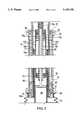
- FIG. 1is a diagrammatic axial cross-sectional view of an embodiment of an elastomeric shock absorber according to the present invention
- FIG. 2is a partial axial cross-sectional view of the embodiment of FIG. 1 with a portion broken away and on a larger scale than FIG. 1;
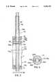
- FIG. 3is an axial cross-sectional view of the hydraulic damping subassembly of the embodiment of FIGS. 1 and 2;
- FIG. 4is an end cross-sectional view of the hydraulic damper subassembly, taken along the line 4--4 of FIG. 3;
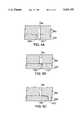
- FIGS. 5A, 5B, and 5Care detail fragmentary side cross-sectional views of another form of controllable bypass of the hydraulic damper.
- the bicycle front wheel(not shown) is mounted on the lower ends of front fork blades 10 that extend outwardly and then downwardly from either side of a fork crown 11.
- the front forkis telescopically supported by the head tube 20 of the bicycle frame.
- An outer cylinder or tube 40is rotatably mounted within the head tube 20 on upper and lower headset roller bearings 22, 24 that are housed within shoulders in respective upper and lower head tube collars 23, 25.
- An inner cylinder or tube 90is coaxially and telescopically mounted within the outer tube 40 with needle bearings 30 interposed between the inner tube 90 and the outer tube 40 to provide a low-friction telescoping mechanism.
- a preferred arrangement of the needle bearing mechanismis described and shown in U.S.
- a lower collar 45is attached to the outer tube 40 by a threaded connection 45a, and an extensible bellows boot 15 is secured between the lower collar 45 and the fork crown 11.
- the boot 15readily extends and contracts lengthwise with the motion of the suspension and keeps debris and dust from entering the internal mechanisms of the shock absorber.
- the lower end of the inner tube 90is received by and affixed to the fork crown 11 and extends upwardly and telescopically into the lower portion of the outer tube 40.
- the needle bearing mechanism 30permits the outer tube 40 to easily slide upwardly and downwardly relative to the inner tube.
- Spring support of the relative motion of the inner and outer tubesis provided by an elongated elastomeric spring element 84 that is received within the lower portion of the inner tube 90.
- the elastomeric spring element 84is compressed between a preload piston 82 and a bottom cap 86, which closes the bottom end of the inner tube 90.
- the bottom cap 86is held in place in the lower end of the inner tube 90 by a "Circlip" 88 which is received in an internal annular groove.
- the tubes 40 and 90are preferably circular in cross-section but may be square or some other suitable shape.
- the preload piston 82is integral with the lower end of a preload shaft 80 that extends upwardly telescopically through a through-tube 60 that is positioned concentrically within the tubes 40 and 90 and extends upwardly to the top of the shock absorber and through a central threaded hole 54 in a top cap 50.
- the top cap 50is affixed to the outer tube 40 by a threaded connection 52 and has a pair of holes 53 which allow insertion of an appropriate tool to assist in tightening or removing the cap 50.
- the manner of attachment of the through-tube 60 to the cap 50is described below; suffice it to say at this point that the through-tube is attached to the cap axially and is rotatable relative to the cap.
- the through-tube 60includes threads 64 along the upper portion of its internal wall.
- An adjustment screw 56threads into the internal threads 64 of the through-tube.
- the preload shaft 80is axially movable in a sliding relationship relative to the through-tube 60. Its axial position is established by the adjustment screw 56 by means of the threaded connection with the through-tube, a suitable tool such as an Allen head wrench being used to turn the adjustment screw 56 and adjust its position axially relative to the through-tube.
- a suitable toolsuch as an Allen head wrench
- the preload adjustmentin the preferred embodiment, by means of the preload shaft 80 is accomplished without reducing the maximum travel capacity for the shock absorber. Moreover, since the spring rate of the elastomeric spring element 84 increases as it is compressed, increasing the preload also increases the spring rate. Thus, a lightweight rider who selects a light preload is provided with a lower spring rate than a heavy rider who applies a higher preload.
- a single spring elementprovides progressive rate adjustability, thereby eliminating the need to change elastomers for different riders and/or riding conditions.
- the elastomeric spring element 84operates primarily as a spring. According to the present invention, additional damping that is adjustable "on the fly” is incorporated into the telescoping motion. In a preferred embodiment, such damping is provided by a hydraulic damping unit 70.
- the damping unit 70is received within the upper portion of the shock absorber above the elastomeric spring 84 and is provided by a piston/cylinder, the cylinder forming a hydraulic chamber 71 that is annular and is defined internally by the through-tube 60, which is a moving wall for the annular chamber, and externally by a cylinder member 72. External threads 74a and a flange portion 74b of the cylinder member 72 provide a threaded and abutting connection of the cylinder member to the upper end of the inner tube 90, which is internally threaded.
- a piston member 76 of the damping unit 70has an annular piston body 76a that is received within the annular chamber and a tubular piston shaft 76b that extends upwardly to the top of the shock absorber and is affixed by a threaded connection to the threads 54 of the cap 50.
- the upper portion of the through-tube 60is of a lesser outer diameter than the lower portion, and the bottom of the piston body 76a engages a shoulder 60a on the upper end of the larger diameter lower portion of the through-tube.
- the preload of the elastomeric spring 84pushes up on the through-tube and maintains engagement between the shoulder 60a and the piston body 76a, and downward movement of the piston 76 with the outer tube 40 is transmitted to the through-tube at the shoulder 60a, thus connecting the through-tube to the cap 50.
- the piston member 76 and the through-tubeare movable together axially up and down within the chamber 71 as the outer tube 40 moves up and down relative to the inner tube 90.
- the piston member 76is shown in its uppermost position in the drawings.
- a lower end cap 77is suitably affixed, such as by a rolled joint, to the lower end of the cylinder member 72 and is sealed to the through-tube 60 by a seal 77a.
- an upper end cap 78is affixed to the upper end of the cylinder member and sealed to the piston rod 76b by a seal 78a.
- the outer diameters of the larger lower portion of the through-tube 60 and of the piston rod 76bare equal. Accordingly, the volume of the annular chamber of the damping unit remains constant throughout the range of motion of the piston member within the annular chamber.
- the chamber 71is filled with a suitable hydraulic liquid such as oil, and the piston has associated with it a controllable bypass that can be adjusted to change the rate of flow of the hydraulic liquid between the sections of the chamber on opposite sides of the piston body 76a, one of which may be complete so that the shock absorber is completely locked out.
- a suitable hydraulic liquidsuch as oil
- the pistonhas associated with it a controllable bypass that can be adjusted to change the rate of flow of the hydraulic liquid between the sections of the chamber on opposite sides of the piston body 76a, one of which may be complete so that the shock absorber is completely locked out.
- the controllable bypassincludes a damper control disc 100 that is received on the through-tube 60 immediately below the piston body 76a.
- the through-tubehas flats 60b that couple the disc 100 to the through-tube for rotation and also provide shoulders at the lower face of the disc that affix the disc to the through-tube axially.
- the control disc 100has a hole 101 that in one position of the disc relative to the piston body 76 registers with a hole 76c in the piston body 76a.
- a detent 103is engaged between the disc 100 of the piston body and enables the position of the disc rotationally relative to the piston body to be held in either of two fixed positions.
- the detent 103consists of a pin 103a on the disc 100 that extends into an elongated groove 103b in the piston 76.
- the piston 76is made of a moderately compressible material, and when the disc is rotated by a control knob or lever 104 at the top of the through tube 60, the wall of the groove in the piston deforms to enable the pin to move along the groove.
- the resiliency of the pistonmaintains the pin 103b in one or the other end of the groove.
- the detent 103is maintaining the relative positions of the disc and piston such that the hole 101 in the disc is in register with the hole 76c in the piston, thereby allowing fluid to flow through the controllable bypass.
- FIGS. 5A, 5B, and 5Cshow one form of controllable bypass which provides for variable damping rates established by holding the rotational position of the disc 101' at any of an infinite number of positions for continuously variable fluid flow rates through the bypass.
- the hole 76c through the piston bodyis fully open to the hole 101' in the disc 100', thus permitting hydraulic liquid to flow across the piston relatively easily.
- a shallow part of a groove 102registers with the hole 76b, thus restricting the flow across the piston.
- the bypassis closed.
- the controllable bypassallows the rider to set the damping of the shock absorber to a selected point between a minimum restriction on oil flow (FIG. 5A), which provides a "soft" ride, and a complete restriction on oil flow (FIG. 5C), which locks out the shock absorber.
- the bypasscan take various other forms, such as a series of different size holes in either the piston body or the control disc, an elongated hole in one of the members that is oriented obliquely to the radial and progressively closes off a hole in the other member, and grooves in the faces of both members of variable depths or variable degrees of overlap.
- the shock absorberalso includes a top-out cushioning bumper 79 of elastomeric material positioned between the piston body 76a and the end cap 78 to provide a cushioning effect during top-out, cushioning the system during rebound after large impacts.
- the bumperis donut-shaped and may be made of any suitable elastomeric material.
- the preferred material for the elastomeric spring element 84is microcellular polyurethane foam of a relatively high density (0.65 gm/cc). Such a shock material is available from Freudenberg-NOK, Manchester, N.H., under the trade name AUZ 2500.
- a bottom-out bumper(such as a snubber) may be located between the fork crown 11 and the lower collar 45. Such a location permits a large diameter cushioning member to be used. Alternately, a bottom-out bumper may be positioned adjacent the lower end cap 77 of the damping unit.
Landscapes
- Engineering & Computer Science (AREA)
- General Engineering & Computer Science (AREA)
- Mechanical Engineering (AREA)
- Health & Medical Sciences (AREA)
- Child & Adolescent Psychology (AREA)
- Fluid-Damping Devices (AREA)
Abstract
Description
Claims (12)
Priority Applications (1)
| Application Number | Priority Date | Filing Date | Title |
|---|---|---|---|
| US08/191,298US5449155A (en) | 1993-08-09 | 1994-02-03 | Suspension skock absorber for bicycles |
Applications Claiming Priority (2)
| Application Number | Priority Date | Filing Date | Title |
|---|---|---|---|
| US10397993A | 1993-08-09 | 1993-08-09 | |
| US08/191,298US5449155A (en) | 1993-08-09 | 1994-02-03 | Suspension skock absorber for bicycles |
Related Parent Applications (1)
| Application Number | Title | Priority Date | Filing Date |
|---|---|---|---|
| US10397993AContinuation-In-Part | 1993-08-09 | 1993-08-09 |
Publications (1)
| Publication Number | Publication Date |
|---|---|
| US5449155Atrue US5449155A (en) | 1995-09-12 |
Family
ID=22298047
Family Applications (1)
| Application Number | Title | Priority Date | Filing Date |
|---|---|---|---|
| US08/191,298Expired - LifetimeUS5449155A (en) | 1993-08-09 | 1994-02-03 | Suspension skock absorber for bicycles |
Country Status (1)
| Country | Link |
|---|---|
| US (1) | US5449155A (en) |
Cited By (43)
| Publication number | Priority date | Publication date | Assignee | Title |
|---|---|---|---|---|
| WO1997009229A1 (en)* | 1995-09-05 | 1997-03-13 | Sportech L L C | Suspension device for reducing transmission of shock through bicycle components |
| EP0805101A1 (en)* | 1996-04-29 | 1997-11-05 | Spinner Industry Co. Ltd. | Shock absorbing assembly for a bicycle |
| WO1999003725A1 (en) | 1997-07-16 | 1999-01-28 | Rockshox, Inc. | Bicycle fork suspension having a single primary compression spring system |
| US5899478A (en)* | 1996-09-30 | 1999-05-04 | Woodside; Terence D. | Stability maintaining shock absorbing bicycle front fork and trailing arm assembly |
| US5941351A (en)* | 1997-03-21 | 1999-08-24 | Chrysler Corporation | Suspension strut assembly |
| US6089585A (en)* | 1996-12-19 | 2000-07-18 | Bayerische Motoren Werke Aktiengesellschaft | Telescopically compressible wheel suspension |
| US6152472A (en)* | 1996-09-30 | 2000-11-28 | Engineered Progression Inc. | Stability maintaining and shock absorbing front fork assembly for bicycles |
| EP1079139A1 (en)* | 1999-07-10 | 2001-02-28 | Chin-Song Tsai | Adjustable pneumatic shock absorber for use with the front fork of a bicycle |
| US20030075407A1 (en)* | 2001-10-23 | 2003-04-24 | Taylor Douglas P. | Shock-isolation structure |
| US20050023794A1 (en)* | 2003-07-31 | 2005-02-03 | Michael Czysz | Coaxial steering and suspension for motorcycle |
| KR100623276B1 (en)* | 2000-04-20 | 2006-09-12 | 주식회사 만도 | Damping force variable shock absorber |
| US20070194553A1 (en)* | 2006-02-06 | 2007-08-23 | Michael Czysz | Front End Lateral Suspension |
| NL1033290C2 (en)* | 2006-01-27 | 2008-03-12 | Giant Mfg Co | Shock-absorbing device for a bicycle. |
| US20080129009A1 (en)* | 2006-02-06 | 2008-06-05 | Motoczysz Llc | Front end lateral suspension |
| CN102691738A (en)* | 2012-06-11 | 2012-09-26 | 谢宁 | Single-rod magnetorheological elastomer rectangular shock absorber |
| US10196106B1 (en) | 2017-07-27 | 2019-02-05 | Trvstper, Inc. | Suspension assembly for a cycle |
| US10300979B2 (en) | 2017-07-27 | 2019-05-28 | Trvstper, Inc. | Suspension assembly for a bicycle |
| US10308312B2 (en) | 2017-07-27 | 2019-06-04 | Trvstper, Inc. | Suspension assembly for a cycle |
| USD859125S1 (en) | 2018-02-08 | 2019-09-10 | Trvstper, Inc. | Cycle suspension rebound knob |
| USD860062S1 (en) | 2018-02-08 | 2019-09-17 | Trvstper, Inc. | Cycle suspension assembly |
| USD860061S1 (en) | 2018-02-08 | 2019-09-17 | Trvstper, Inc. | Cycle suspension assembly |
| USD861542S1 (en) | 2018-02-08 | 2019-10-01 | Trvstper, Inc. | Cycle suspension assembly |
| US10518836B2 (en) | 2017-07-27 | 2019-12-31 | Trvstper, Inc. | Suspension assembly for a cycle |
| US10518839B2 (en) | 2017-08-29 | 2019-12-31 | Trvstper, Inc. | Inline shock absorber with coil spring for a cycle wheel suspension assembly |
| US10526039B2 (en) | 2017-07-27 | 2020-01-07 | Trvstper, Inc. | Suspension assembly for a cycle |
| US10526040B2 (en) | 2017-08-28 | 2020-01-07 | Trvstper, Inc. | Inline shock absorber with gas spring for a cycle wheel suspension assembly |
| US10549812B2 (en) | 2017-08-28 | 2020-02-04 | Trvstper, Inc. | Inline shock absorber with gas spring for a cycle wheel suspension assembly |
| US10549813B2 (en) | 2017-08-29 | 2020-02-04 | Trvstper, Inc. | Inline shock absorber with coil spring for a cycle wheel suspension assembly |
| USD880370S1 (en) | 2018-02-08 | 2020-04-07 | Trvstper, Inc. | Cycle suspension assembly |
| USD880372S1 (en) | 2018-02-08 | 2020-04-07 | Trvstper, Inc. | Cycle suspension assembly |
| USD880371S1 (en) | 2018-02-08 | 2020-04-07 | Trvstper, Inc. | Cycle suspension assembly |
| USD880369S1 (en) | 2018-02-08 | 2020-04-07 | Trvstper, Inc. | Cycle suspension assembly |
| US11084552B2 (en) | 2018-09-25 | 2021-08-10 | Specialized Bicycle Components, Inc. | Simplified gas spring setup for a trailing link cycle wheel suspension |
| US11208172B2 (en) | 2018-10-05 | 2021-12-28 | Specialized Bicycle Components, Inc. | Suspension pivot assemblies having a retention feature |
| US11230348B2 (en) | 2018-09-25 | 2022-01-25 | Specialized Bicycle Components, Inc. | Trailing link cycle wheel suspension assembly having gas pistons with unequal gas piston areas |
| US11230347B2 (en) | 2018-09-25 | 2022-01-25 | Specialized Bicycle Components, Inc. | Cycle wheel suspension assembly having gas pistons with unequal gas piston areas |
| US11230346B2 (en) | 2018-09-25 | 2022-01-25 | Specialized Bicycle Components Inc. | Cycle wheel suspension assembly having gas pistons with unequal gas piston areas |
| US11273887B2 (en) | 2018-10-16 | 2022-03-15 | Specialized Bicycle Components, Inc. | Cycle suspension with travel indicator |
| US11345432B2 (en) | 2018-10-12 | 2022-05-31 | Specialized Bicycle Components, Inc. | Suspension assembly for a cycle having a fork arm with dual opposing tapers |
| US11524744B2 (en) | 2019-04-09 | 2022-12-13 | Specialized Bicycle Components, Inc. | Cycle suspension with rotation sensor |
| US11904977B2 (en) | 2019-10-11 | 2024-02-20 | Eko Sport, Inc. | Compensator |
| US11945539B2 (en) | 2018-09-07 | 2024-04-02 | Specialized Bicycle Components, Inc. | Dual sided suspension assembly for a cycle wheel |
| US12319381B2 (en) | 2018-09-25 | 2025-06-03 | Specialized Bicycle Components, Inc. | Trailing link cycle wheel suspension assembly having gas pistons with unequal gas piston areas |
Citations (18)
| Publication number | Priority date | Publication date | Assignee | Title |
|---|---|---|---|---|
| FR362619A (en)* | 1906-01-23 | 1906-07-02 | Emile Lemoine | Brake for cycles |
| US1273011A (en)* | 1917-05-24 | 1918-07-16 | Thomas J Snyder | Shock-absorber. |
| GB264003A (en)* | 1925-12-15 | 1927-01-13 | Bowden Wire Ltd | Improvements in or connected with shock absorbers or vibration dampers for use with vehicles, machinery, shafting, or other apparatus having a part movable relatively to another part |
| GB469697A (en)* | 1936-05-16 | 1937-07-30 | Reginald Roberts | Improvements relating to spring forks for cycles and like vehicles |
| GB529305A (en)* | 1938-04-12 | 1940-11-19 | Hans Oesch | Improvements in spring frames for motor-cycles and like vehicles |
| GB585122A (en)* | 1945-02-06 | 1947-01-30 | Sydney William Hardy | Improvements in shock absorbing means for motorbicycle and tricycle wheels |
| US2561156A (en)* | 1946-01-11 | 1951-07-17 | Lars O Thorkildsen | Bicycle fork |
| US2771968A (en)* | 1947-02-04 | 1956-11-27 | Mercier Jean | Shock absorber |
| US3369802A (en)* | 1966-02-02 | 1968-02-20 | Miner Inc W H | Adjustable damped spring |
| US3376031A (en)* | 1965-10-19 | 1968-04-02 | Destech Labs Inc | Shock absorber |
| US3420341A (en)* | 1967-10-16 | 1969-01-07 | Jonathan N Keehn | Variable shock absorber |
| US4191280A (en)* | 1976-08-23 | 1980-03-04 | Uni-Drive (Tractors) Limited | Mechanical link members |
| US4591030A (en)* | 1984-04-16 | 1986-05-27 | Tayco Developments, Inc. | Elastomeric damped shock absorber |
| US4815763A (en)* | 1988-06-13 | 1989-03-28 | Hartmann Dirck T | Shock absorber for mountain bicycles |
| EP0420610A1 (en)* | 1989-09-28 | 1991-04-03 | Cannondale Corporation | Bicycle suspension system |
| US5031732A (en)* | 1988-03-02 | 1991-07-16 | Fried. Krupp Gmbh | Shock absorber for a vehicle |
| US5104101A (en)* | 1990-04-25 | 1992-04-14 | Miner Enterprises, Inc. | Buffer cartridge |
| US5271485A (en)* | 1992-09-23 | 1993-12-21 | Predator Systems Inc. | Hydraulic damper |
- 1994
- 1994-02-03USUS08/191,298patent/US5449155A/ennot_activeExpired - Lifetime
Patent Citations (18)
| Publication number | Priority date | Publication date | Assignee | Title |
|---|---|---|---|---|
| FR362619A (en)* | 1906-01-23 | 1906-07-02 | Emile Lemoine | Brake for cycles |
| US1273011A (en)* | 1917-05-24 | 1918-07-16 | Thomas J Snyder | Shock-absorber. |
| GB264003A (en)* | 1925-12-15 | 1927-01-13 | Bowden Wire Ltd | Improvements in or connected with shock absorbers or vibration dampers for use with vehicles, machinery, shafting, or other apparatus having a part movable relatively to another part |
| GB469697A (en)* | 1936-05-16 | 1937-07-30 | Reginald Roberts | Improvements relating to spring forks for cycles and like vehicles |
| GB529305A (en)* | 1938-04-12 | 1940-11-19 | Hans Oesch | Improvements in spring frames for motor-cycles and like vehicles |
| GB585122A (en)* | 1945-02-06 | 1947-01-30 | Sydney William Hardy | Improvements in shock absorbing means for motorbicycle and tricycle wheels |
| US2561156A (en)* | 1946-01-11 | 1951-07-17 | Lars O Thorkildsen | Bicycle fork |
| US2771968A (en)* | 1947-02-04 | 1956-11-27 | Mercier Jean | Shock absorber |
| US3376031A (en)* | 1965-10-19 | 1968-04-02 | Destech Labs Inc | Shock absorber |
| US3369802A (en)* | 1966-02-02 | 1968-02-20 | Miner Inc W H | Adjustable damped spring |
| US3420341A (en)* | 1967-10-16 | 1969-01-07 | Jonathan N Keehn | Variable shock absorber |
| US4191280A (en)* | 1976-08-23 | 1980-03-04 | Uni-Drive (Tractors) Limited | Mechanical link members |
| US4591030A (en)* | 1984-04-16 | 1986-05-27 | Tayco Developments, Inc. | Elastomeric damped shock absorber |
| US5031732A (en)* | 1988-03-02 | 1991-07-16 | Fried. Krupp Gmbh | Shock absorber for a vehicle |
| US4815763A (en)* | 1988-06-13 | 1989-03-28 | Hartmann Dirck T | Shock absorber for mountain bicycles |
| EP0420610A1 (en)* | 1989-09-28 | 1991-04-03 | Cannondale Corporation | Bicycle suspension system |
| US5104101A (en)* | 1990-04-25 | 1992-04-14 | Miner Enterprises, Inc. | Buffer cartridge |
| US5271485A (en)* | 1992-09-23 | 1993-12-21 | Predator Systems Inc. | Hydraulic damper |
Cited By (56)
| Publication number | Priority date | Publication date | Assignee | Title |
|---|---|---|---|---|
| WO1997009229A1 (en)* | 1995-09-05 | 1997-03-13 | Sportech L L C | Suspension device for reducing transmission of shock through bicycle components |
| US5704626A (en)* | 1995-09-05 | 1998-01-06 | Kesinger; Donald A. | Suspension device for reducing transmission of shock through bicycle components |
| EP0805101A1 (en)* | 1996-04-29 | 1997-11-05 | Spinner Industry Co. Ltd. | Shock absorbing assembly for a bicycle |
| US5899478A (en)* | 1996-09-30 | 1999-05-04 | Woodside; Terence D. | Stability maintaining shock absorbing bicycle front fork and trailing arm assembly |
| US6152472A (en)* | 1996-09-30 | 2000-11-28 | Engineered Progression Inc. | Stability maintaining and shock absorbing front fork assembly for bicycles |
| US6089585A (en)* | 1996-12-19 | 2000-07-18 | Bayerische Motoren Werke Aktiengesellschaft | Telescopically compressible wheel suspension |
| US5941351A (en)* | 1997-03-21 | 1999-08-24 | Chrysler Corporation | Suspension strut assembly |
| WO1999003725A1 (en) | 1997-07-16 | 1999-01-28 | Rockshox, Inc. | Bicycle fork suspension having a single primary compression spring system |
| EP1079139A1 (en)* | 1999-07-10 | 2001-02-28 | Chin-Song Tsai | Adjustable pneumatic shock absorber for use with the front fork of a bicycle |
| KR100623276B1 (en)* | 2000-04-20 | 2006-09-12 | 주식회사 만도 | Damping force variable shock absorber |
| US20030075407A1 (en)* | 2001-10-23 | 2003-04-24 | Taylor Douglas P. | Shock-isolation structure |
| US6640941B2 (en)* | 2001-10-23 | 2003-11-04 | Tayco Developments, Inc. | Shock-isolation structure |
| US20050023794A1 (en)* | 2003-07-31 | 2005-02-03 | Michael Czysz | Coaxial steering and suspension for motorcycle |
| US7111700B2 (en) | 2003-07-31 | 2006-09-26 | Motoczysz Llc | Coaxial steering and suspension for motorcycle |
| US20060279059A1 (en)* | 2003-07-31 | 2006-12-14 | Michael Czysz | Coaxial steering and suspension for motorcycle |
| US7578514B2 (en)* | 2003-07-31 | 2009-08-25 | Motoczysz Llc | Coaxial steering and suspension for motorcycle |
| NL1033290C2 (en)* | 2006-01-27 | 2008-03-12 | Giant Mfg Co | Shock-absorbing device for a bicycle. |
| US20080129009A1 (en)* | 2006-02-06 | 2008-06-05 | Motoczysz Llc | Front end lateral suspension |
| US7490843B2 (en) | 2006-02-06 | 2009-02-17 | Motoczysz Llc | Front end lateral suspension |
| US20070194553A1 (en)* | 2006-02-06 | 2007-08-23 | Michael Czysz | Front End Lateral Suspension |
| US7832752B2 (en) | 2006-02-06 | 2010-11-16 | Motoczysz Llc | Front end lateral suspension |
| CN102691738A (en)* | 2012-06-11 | 2012-09-26 | 谢宁 | Single-rod magnetorheological elastomer rectangular shock absorber |
| CN102691738B (en)* | 2012-06-11 | 2013-09-18 | 谢宁 | Single-rod magnetorheological elastomer rectangular shock absorber |
| US10308312B2 (en) | 2017-07-27 | 2019-06-04 | Trvstper, Inc. | Suspension assembly for a cycle |
| US10300979B2 (en) | 2017-07-27 | 2019-05-28 | Trvstper, Inc. | Suspension assembly for a bicycle |
| US10196106B1 (en) | 2017-07-27 | 2019-02-05 | Trvstper, Inc. | Suspension assembly for a cycle |
| US10689061B2 (en) | 2017-07-27 | 2020-06-23 | Trvstper, Inc. | Suspension assembly for a cycle |
| US10549815B2 (en) | 2017-07-27 | 2020-02-04 | Trvstper, Inc. | Suspension assembly for a bicycle |
| US10518836B2 (en) | 2017-07-27 | 2019-12-31 | Trvstper, Inc. | Suspension assembly for a cycle |
| US10526039B2 (en) | 2017-07-27 | 2020-01-07 | Trvstper, Inc. | Suspension assembly for a cycle |
| US10549812B2 (en) | 2017-08-28 | 2020-02-04 | Trvstper, Inc. | Inline shock absorber with gas spring for a cycle wheel suspension assembly |
| US10526040B2 (en) | 2017-08-28 | 2020-01-07 | Trvstper, Inc. | Inline shock absorber with gas spring for a cycle wheel suspension assembly |
| US10549813B2 (en) | 2017-08-29 | 2020-02-04 | Trvstper, Inc. | Inline shock absorber with coil spring for a cycle wheel suspension assembly |
| US10518839B2 (en) | 2017-08-29 | 2019-12-31 | Trvstper, Inc. | Inline shock absorber with coil spring for a cycle wheel suspension assembly |
| USD860061S1 (en) | 2018-02-08 | 2019-09-17 | Trvstper, Inc. | Cycle suspension assembly |
| USD861542S1 (en) | 2018-02-08 | 2019-10-01 | Trvstper, Inc. | Cycle suspension assembly |
| USD860062S1 (en) | 2018-02-08 | 2019-09-17 | Trvstper, Inc. | Cycle suspension assembly |
| USD880370S1 (en) | 2018-02-08 | 2020-04-07 | Trvstper, Inc. | Cycle suspension assembly |
| USD880372S1 (en) | 2018-02-08 | 2020-04-07 | Trvstper, Inc. | Cycle suspension assembly |
| USD880371S1 (en) | 2018-02-08 | 2020-04-07 | Trvstper, Inc. | Cycle suspension assembly |
| USD880369S1 (en) | 2018-02-08 | 2020-04-07 | Trvstper, Inc. | Cycle suspension assembly |
| USD859125S1 (en) | 2018-02-08 | 2019-09-10 | Trvstper, Inc. | Cycle suspension rebound knob |
| US11945539B2 (en) | 2018-09-07 | 2024-04-02 | Specialized Bicycle Components, Inc. | Dual sided suspension assembly for a cycle wheel |
| US11230347B2 (en) | 2018-09-25 | 2022-01-25 | Specialized Bicycle Components, Inc. | Cycle wheel suspension assembly having gas pistons with unequal gas piston areas |
| US11230348B2 (en) | 2018-09-25 | 2022-01-25 | Specialized Bicycle Components, Inc. | Trailing link cycle wheel suspension assembly having gas pistons with unequal gas piston areas |
| US11230346B2 (en) | 2018-09-25 | 2022-01-25 | Specialized Bicycle Components Inc. | Cycle wheel suspension assembly having gas pistons with unequal gas piston areas |
| US11084552B2 (en) | 2018-09-25 | 2021-08-10 | Specialized Bicycle Components, Inc. | Simplified gas spring setup for a trailing link cycle wheel suspension |
| US12319381B2 (en) | 2018-09-25 | 2025-06-03 | Specialized Bicycle Components, Inc. | Trailing link cycle wheel suspension assembly having gas pistons with unequal gas piston areas |
| US11208172B2 (en) | 2018-10-05 | 2021-12-28 | Specialized Bicycle Components, Inc. | Suspension pivot assemblies having a retention feature |
| US11345432B2 (en) | 2018-10-12 | 2022-05-31 | Specialized Bicycle Components, Inc. | Suspension assembly for a cycle having a fork arm with dual opposing tapers |
| US11273887B2 (en) | 2018-10-16 | 2022-03-15 | Specialized Bicycle Components, Inc. | Cycle suspension with travel indicator |
| US11820457B2 (en) | 2018-10-16 | 2023-11-21 | Specialized Bicycle Components, Inc. | Cycle suspension with travel indicator |
| US12344346B2 (en) | 2018-10-16 | 2025-07-01 | Specialized Bicycle Components, Inc. | Cycle suspension with travel indicator |
| US11524744B2 (en) | 2019-04-09 | 2022-12-13 | Specialized Bicycle Components, Inc. | Cycle suspension with rotation sensor |
| US12258095B2 (en) | 2019-04-09 | 2025-03-25 | Specialized Bicycle Components, Inc. | Cycle suspension with rotation sensor |
| US11904977B2 (en) | 2019-10-11 | 2024-02-20 | Eko Sport, Inc. | Compensator |
Similar Documents
| Publication | Publication Date | Title |
|---|---|---|
| US5449155A (en) | Suspension skock absorber for bicycles | |
| US10337584B2 (en) | Bicycle fork having lock-out, blow-off, and adjustable blow-off threshold | |
| US6095541A (en) | Adjustable gas spring suspension system | |
| US7011325B2 (en) | Adjustable length suspension fork for a bicycle | |
| US5478099A (en) | Bicycle wheel fork assembly | |
| EP1687197B1 (en) | Adjustable gas spring suspension system | |
| EP0420610B1 (en) | Bicycle suspension system | |
| US5720473A (en) | Shock absorber | |
| US20010040078A1 (en) | Damping apparatus for bicycle forks | |
| TWI863263B (en) | Suspension fork for a bicycle | |
| JPH06270874A (en) | Front wheel suspension for bicycle | |
| WO1999059860A1 (en) | Electronic suspension system for a vehicle | |
| EP1597493A2 (en) | Inertia valve shock absorber | |
| JPH1111374A (en) | Bicycle | |
| JP3415937B2 (en) | Front fork height adjustment mechanism | |
| US20250313055A1 (en) | Valve-controlled fluid circuits for rebound damping adjustment | |
| JPS6120342Y2 (en) |
Legal Events
| Date | Code | Title | Description |
|---|---|---|---|
| AS | Assignment | Owner name:CANNONDALE CORPORATION, CONNECTICUT Free format text:ASSIGNMENT OF ASSIGNORS INTEREST;ASSIGNOR:MACK, CHRISTOPH;REEL/FRAME:006940/0225 Effective date:19940228 | |
| STCF | Information on status: patent grant | Free format text:PATENTED CASE | |
| FEPP | Fee payment procedure | Free format text:PAYOR NUMBER ASSIGNED (ORIGINAL EVENT CODE: ASPN); ENTITY STATUS OF PATENT OWNER: LARGE ENTITY | |
| FPAY | Fee payment | Year of fee payment:4 | |
| AS | Assignment | Owner name:NATIONSBANK, N.A., AS AGENT, NORTH CAROLINA Free format text:SECURITY AGREEMENT;ASSIGNOR:CANNONDALE CORPORATION;REEL/FRAME:009845/0691 Effective date:19990122 | |
| AS | Assignment | Owner name:ABLECO FINANCE LLC, AS AGENT, NEW YORK Free format text:SECURITY AGREEMENT;ASSIGNOR:CANNONDALE CORPORATION;REEL/FRAME:011177/0152 Effective date:20000630 | |
| AS | Assignment | Owner name:CANNONDALE CORPORATION, CONNECTICUT Free format text:RELEASE OF PATENT ASSIGNMENT;ASSIGNOR:ABLECO FINANCE LLC;REEL/FRAME:013380/0469 Effective date:20020726 | |
| AS | Assignment | Owner name:CIT GROUP/BUSINESS CREDIT, INC., NEW YORK Free format text:SECURITY AGREEMENT;ASSIGNOR:CANNONDALE CORPORATION;REEL/FRAME:013467/0921 Effective date:20020726 | |
| AS | Assignment | Owner name:PEGASUS PARTNERS II, L.P., CONNECTICUT Free format text:SECURITY AGREEMENT;ASSIGNOR:CANNONDALE CORPORATION;REEL/FRAME:013660/0896 Effective date:20020726 | |
| REMI | Maintenance fee reminder mailed | ||
| FPAY | Fee payment | Year of fee payment:8 | |
| SULP | Surcharge for late payment | Year of fee payment:7 | |
| AS | Assignment | Owner name:BICYCLE BUSINESS ACQUISITION CORP., CONNECTICUT Free format text:ASSIGNMENT OF ASSIGNORS INTEREST;ASSIGNOR:CANNONDALE CORPORATION;REEL/FRAME:014083/0822 Effective date:20030502 Owner name:CANNONDALE BICYCLE CORPORATION, CONNECTICUT Free format text:CHANGE OF NAME;ASSIGNOR:BICYCLE BUSINESS ACQUISITION CORP.;REEL/FRAME:014083/0342 Effective date:20030506 Owner name:CANNONDALE CORPORATION, CONNECTICUT Free format text:RELEASE OF SECURITY INTEREST;ASSIGNOR:PEGASUS PARTNERS II, L.P.;REEL/FRAME:014083/0799 Effective date:20030502 Owner name:PEGASUS PARTNERS II, L.P., CONNECTICUT Free format text:SECURITY AGREEMENT;ASSIGNOR:BICYCLE BUSINESS ACQUISITION CORP.;REEL/FRAME:014097/0616 Effective date:20030502 | |
| AS | Assignment | Owner name:CIT GROUP/BUSINESS CREDIT INC., NEW YORK Free format text:ASSIGNMENT FOR SECURITY;ASSIGNOR:BICYCLE BUSINESS ACQUISTION CORP.;REEL/FRAME:014227/0363 Effective date:20030417 | |
| AS | Assignment | Owner name:BLACKROCK KELSO CAPITAL CORPORATION, AS AGENT, NEW Free format text:ASSIGNMENT OF ASSIGNORS INTEREST;ASSIGNOR:CANNONDALE BICYCLE CORPORATION;REEL/FRAME:017025/0596 Effective date:20051230 | |
| FPAY | Fee payment | Year of fee payment:12 | |
| AS | Assignment | Owner name:CANNONDALE BICYCLE CORPORATION, CONNECTICUT Free format text:RELEASE OF SECURITY INTEREST;ASSIGNOR:PEGASUS PARTNERS II, L.P.;REEL/FRAME:020468/0267 Effective date:20080128 Owner name:CANNONDALE BICYCLE CORPORATION, CONNECTICUT Free format text:RELEASE OF SECURITY INTEREST;ASSIGNOR:BLACKROCK KELSO CAPITAL;REEL/FRAME:020468/0235 Effective date:20080204 | |
| AS | Assignment | Owner name:CANNONDALE BICYCLE CORPORATION, F/K/A BICYCLE BUSI Free format text:RELEASE OF SECURITY INTEREST;ASSIGNOR:CIT GROUP/BUSINESS CREDIT, INC.;REEL/FRAME:020497/0845 Effective date:20080204 Owner name:CANNONDALE BICYCLE CORPORATION, F/K/A BICYCLE BUSI Free format text:RELEASE OF SECURITY INTEREST;ASSIGNOR:CIT GROUP/BUSINESS CREDIT, INC.;REEL/FRAME:020497/0647 Effective date:20080204 | |
| AS | Assignment | Owner name:CANNONDALE CORPORATION, CONNECTICUT Free format text:SECURITY RELEASE BY BANKRUPTCY ORDER;ASSIGNORS:BARCLAYS BUSINESS CREDIT, INC.;NATIONSBANK, N.A., AS AGENT;ABLECO FINANCE LLC, AS AGENT;AND OTHERS;REEL/FRAME:020995/0809 Effective date:20030407 |