US5449145A - Valve device for controlling flows in surgical applications - Google Patents
Valve device for controlling flows in surgical applicationsDownload PDFInfo
- Publication number
- US5449145A US5449145AUS08/134,410US13441093AUS5449145AUS 5449145 AUS5449145 AUS 5449145AUS 13441093 AUS13441093 AUS 13441093AUS 5449145 AUS5449145 AUS 5449145A
- Authority
- US
- United States
- Prior art keywords
- conduit
- piston
- valve
- port
- valve body
- Prior art date
- Legal status (The legal status is an assumption and is not a legal conclusion. Google has not performed a legal analysis and makes no representation as to the accuracy of the status listed.)
- Expired - Lifetime
Links
- 230000007704transitionEffects0.000claimsabstractdescription17
- 238000004891communicationMethods0.000claimsdescription12
- 230000006835compressionEffects0.000claimsdescription4
- 238000007906compressionMethods0.000claimsdescription4
- 230000008878couplingEffects0.000claimsdescription3
- 238000010168coupling processMethods0.000claimsdescription3
- 238000005859coupling reactionMethods0.000claimsdescription3
- 230000002262irrigationEffects0.000abstractdescription8
- 238000003973irrigationMethods0.000abstractdescription8
- 239000000523sampleSubstances0.000description16
- 239000012530fluidSubstances0.000description6
- 210000003811fingerAnatomy0.000description3
- 238000000034methodMethods0.000description3
- 230000000994depressogenic effectEffects0.000description2
- 230000004048modificationEffects0.000description2
- 238000012986modificationMethods0.000description2
- 210000003813thumbAnatomy0.000description2
- 230000009471actionEffects0.000description1
- 230000001154acute effectEffects0.000description1
- 239000000853adhesiveSubstances0.000description1
- 230000001070adhesive effectEffects0.000description1
- 239000008280bloodSubstances0.000description1
- 210000004369bloodAnatomy0.000description1
- 238000012864cross contaminationMethods0.000description1
- 230000000694effectsEffects0.000description1
- 239000013536elastomeric materialSubstances0.000description1
- 238000002674endoscopic surgeryMethods0.000description1
- 210000005224forefingerAnatomy0.000description1
- 239000012634fragmentSubstances0.000description1
- 229940113601irrigation solutionDrugs0.000description1
- 238000002357laparoscopic surgeryMethods0.000description1
- 238000004519manufacturing processMethods0.000description1
- 239000000463materialSubstances0.000description1
- 238000000465mouldingMethods0.000description1
- 239000013618particulate matterSubstances0.000description1
- 230000000284resting effectEffects0.000description1
- 238000007789sealingMethods0.000description1
- 239000008174sterile solutionSubstances0.000description1
- 230000001954sterilising effectEffects0.000description1
- 238000004659sterilization and disinfectionMethods0.000description1
- 238000001356surgical procedureMethods0.000description1
Images

Classifications
- F—MECHANICAL ENGINEERING; LIGHTING; HEATING; WEAPONS; BLASTING
- F16—ENGINEERING ELEMENTS AND UNITS; GENERAL MEASURES FOR PRODUCING AND MAINTAINING EFFECTIVE FUNCTIONING OF MACHINES OR INSTALLATIONS; THERMAL INSULATION IN GENERAL
- F16K—VALVES; TAPS; COCKS; ACTUATING-FLOATS; DEVICES FOR VENTING OR AERATING
- F16K27/00—Construction of housing; Use of materials therefor
- F16K27/04—Construction of housing; Use of materials therefor of sliding valves
- F16K27/041—Construction of housing; Use of materials therefor of sliding valves cylindrical slide valves
- A—HUMAN NECESSITIES
- A61—MEDICAL OR VETERINARY SCIENCE; HYGIENE
- A61M—DEVICES FOR INTRODUCING MEDIA INTO, OR ONTO, THE BODY; DEVICES FOR TRANSDUCING BODY MEDIA OR FOR TAKING MEDIA FROM THE BODY; DEVICES FOR PRODUCING OR ENDING SLEEP OR STUPOR
- A61M1/00—Suction or pumping devices for medical purposes; Devices for carrying-off, for treatment of, or for carrying-over, body-liquids; Drainage systems
- A61M1/71—Suction drainage systems
- A61M1/77—Suction-irrigation systems
- A61M1/774—Handpieces specially adapted for providing suction as well as irrigation, either simultaneously or independently
Definitions
- This inventionrelates to low cost valve devices, and more particularly to manually operated valve systems for controlling irrigation and aspiration flows to surgical sites.
- valve deviceThis type of valve device has been used for many years, but earlier units were primarily expensive, complex designs that were intended to be reusable. Further, since the probes were fixed to the valve structure, the surgeon was afforded little opportunity to use the instrument in a variety of operating modes, or manipulate it readily in different positions.
- irrigation and aspiration conduitscouple into the opposite side of the chambers from the common conduit, this arrangement can be used by a right-handed surgeon with the probe extending from one end of the common conduit, or by a left-handed surgeon if the probe is reversed to the opposite end of the common conduit.
- the internal flow pathsare restricted in size, because of the necessity of coupling into and out of side conduits, and because the geometry requires a number of O-ring seals and the use of biasing springs in the bottom of the chamber.
- a valve configuration in accordance with the inventionutilizes a valve barrel of substantially larger size than a base fluid conduit to which it is transversely coupled.
- a wide flow pathincluding an interior transition well that merges into an open section of the conduit.
- a cylindrical slider pistonIn the intermediate region of the barrel is a reduced diameter section within which a cylindrical slider piston is reciprocable, the slider piston having an elongated transverse bore for communication between the port and the transition well.
- the slider pistonis of an elastomeric material and includes circumferential seal rings at each end of its length, such that when the slider piston is in the non-actuated position, the port is sealed off from the transition well.
- the elongated boreextends into the transition region and provides an open communication path along the central axis of the barrel and through each side of the bore.
- this valve arrangementincludes a manually operable key member inserted into the open end of the valve barrel, coupled to the slider piston interior to the valve barrel, and mechanically biased toward the unactuated position by a spring disposed between the upper end of the valve barrel and the inner upper end of the key member.
- the upper end of the valve barrelhas a reduced diameter neck portion and an uppermost circumferential flange against which inner projections on a cylindrical skirt of the key member engage to limit upward movement of the key member.
- the valvemay be constructed of several readily molded parts, which are fitted together and joined in such manner as to enable different support means to be fabricated.
- the inventionalso comprises an improved trumpet valve, manufactured as a disposable, for irrigation/aspiration functions in surgical systems.
- trumpet valvemanufactured as a disposable, for irrigation/aspiration functions in surgical systems.
- two valve barrelsare disposed in spaced apart, upstanding relation, along a common conduit.
- Each valve barrel and slider piston arrangementis as previously described, but the radial ports in the intermediate regions of the valve barrel bodies are disposed along the common plane of the two valve barrels, or at a slight angle outwardly.
- a support pad or surface on the underside of the conduitfits between the thumb and forefinger of a surgeon, whether used in the left hand or the right hand, and the key members can then be actuated with two fingertips in convenient fashion.
- the trumpet valve arrangementcan be utilized with an attachable probe coupled to an output port of the conduit with a conventional threaded male/female connection or with an axial quick disconnect coupling.
- the opposite end of the conduitis typically closed, as with a luer fitting, but can be opened so that an operative element can be extended through the conduit and the probe into the operative site for other purposes, such as cauterizing.
- the base unitincluding the conduit and the transition wells, is conveniently molded as a separate piece with any one of several different support pads being attachable, through the use of different mold cavities in association with the basic mold, which can be closed off if no support pad is to be attached.
- FIG. 1is a perspective view of a typical operative usage of a valve device in accordance with the invention, as employed with an attached probe;
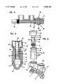
- FIG. 2is an exploded view of a portion of the valve device of FIG. 1;
- FIG. 3is a side sectional view of the device of FIG. 2, showing a single valve barrel and slider piston;
- FIG. 4is a fragmentary perspective view, partially broken away, of a single valve device as utilized in the arrangement of FIGS. 1-3, showing the slider piston in actuated position;
- FIG. 5is a side sectional fragmentary view of a portion of a valve device as in FIGS. 1-4, showing an added instrument coupled through the conduit and the probe;
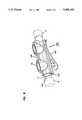
- FIG. 6is a perspective view of a first type of alternate support pad.
- FIGS. 1-4A valve device 10 in accordance with the invention is shown in FIGS. 1-4, to which reference is now made.
- a length of conduit 11is disposed along a given linear axis, defining a conduit path of a predetermined internal diameter.
- the conduit 11has an open port 12 at one end, the port 12 being interiorly threaded to receive a probe 13 which extends in a direction toward a surgical site, this direction predetermining the relationship of other elements in the system, as is described below.
- the opposite end port 14also includes an interior thread, and in this example, is closed off with a luer closure 15.
- First and second valve barrels, 16 and 17 respectively,are coupled to the conduit 11 at spaced apart regions along its length, the valve barrels 16, 17 having central axes lying in a common plane and normal to the central axis of the conduit 11.
- the barrels 16, 17will typically be used in an upstanding relationship relative to the conduit 11, so that relative terms such as vertical, upper and lower are utilized for clarity of description, although it will be appreciated that in operation the device can be angled in different attitudes and ways depending on the circumstances.
- the first barrel 16includes a principal length of an outer diameter section that is substantially greater than the conduit 11.
- the upper section 28is of reduced inner diameter 20 and is then stepped outwardly to a larger diameter section 22 in the lower region.
- the larger diameter sectionmerges into a transition well 24 at the bottom, converging smoothly into the lower half section of the inner conduit 26.
- the inner diameteris larger, but the barrel also includes an upper section of reduced outer diameter 28 terminating in an uppermost circumferential flange 30.
- a key member 32 disposed above this upper section 28has a slightly concave top surface for finger operation, as viewed in FIGS. 1 and 3.
- the key member 32includes a central shaft disposed along the central axis of the barrel 16, and extending downwardly into the reduced inner diameter of section 20.
- an elastomeric slider piston 36of predetermined length and diameter.
- an integral circumferential seal ring 38At the upper end of the slider piston 36 is an integral circumferential seal ring 38 that, when the key member 32 is in the non-actuated position of FIG. 3, is above a side port, described below, in the barrel.
- the lower end of the slider piston 36also includes an integral circumferential seal ring 40 which, as seen in FIG. 3 also is in the reduced inner diameter section 20 in this position.
- an elongated interior bore 42whose length and position are selected relative to a side port shown in dotted lines in FIGS. 3 and 4. Because the side port of the first valve barrel 16 must clear the second valve barrel, the side port is at a slight area to the common plane, as best seen in FIG.
- the interior bore 42is also at a slight angle to the common plane, as seen in FIGS. 3 and 4.
- the elongated interior bore 42still is fully open to the side port, but the lower end of the bore 42 extends down into the larger diameter section 22 of the barrel, providing a flow path in both directions of substantial cross-sectional area relative to the conduit 11 cross-sectional area, as seen in FIG. 4.
- the key member 32is biased toward the non-actuated position by a helical compression spring 46 about the key member shaft 34, and extending between the upper region of the barrel 16 and the under side of the top surface of the key member 32.
- the key member 32also includes a depending cylindrical skirt or flange 50 that has, at its lower edge, two or more inwardly projected tabs 51 which snap over the outer edge of the circumferential flange 30 on the barrel 16, to thereafter define the upper limit of the non-actuated position. Vent apertures 52 in the upper surface of the key member 32 permit air passage to provide free reciprocal movement of the key member 32 without air compression effects.
- the aspiration port 60is at a slight acute angle to the common plane to provide clearance relative to the second barrel 17.
- the irrigation port 62 coupled to the second barrel 17then lies in the common plane, the aspiration and irrigation lines 63, 64 are coupled to the ports 60, 62 respectively, and thereby directed away from the surgical site.
- the surgeon's handfits around a support pad 70 having a concave undersurface 72, with the surgeon's fingers separately fitting over the key members 32 on the two barrels 16, 17.
- the right hand of an operatoris shown, it will be appreciated that the arrangement is symmetrical and that a left-handed operator can use it just as well.
- the barrelsare made separately from the conduit 11 but the joinder line is disposed at the upper end of the transition wells 24, so that the entire support pad 70 and conduit 11, including end ports 12, 14 and transition wells 24 for both barrels, are molded as a single piece, as seen in FIGS. 2 and 3.
- Interlocking lips 67, 68 on the barrel 16 and transition section 24enable easy assembly, using adhesive or bonding material (not shown).
- the surgeonholds the device 10 in one hand, in the position indicated in FIG. 1, with finger control over both key members 32, and with the base support pads 70 resting in the web between thumb and the palm of the hand.
- Flows of sterile irrigation fluid in the line 64 and suction in the aspiration line 63are constantly maintained, as the surgeon places the operative end of the probe 13 at the surgical site, as in laparoscopic or endoscopic surgery. He then simply depresses the appropriate key member 32, placing the key in the actuated position, as seen in FIG. 4, with incoming or outgoing flow finding a large cross-sectional area path between the port and the conduit.
- FIG. 5A different application of the system is depicted in the side sectional view of FIG. 5, wherein the closed end port 14 on the side opposite the surgical site is opened, and used as a fitting for an additional instrument 80, such as a cauterizing needle 82 which can be extended through the conduit 11 and the probe 13 for use concurrently with the probe.
- an additional instrument 80such as a cauterizing needle 82 which can be extended through the conduit 11 and the probe 13 for use concurrently with the probe.
- Thisis a conventional operation with probe systems, and facilitated by the compact, versatile nature of the device.
- half 87 of a quick disconnect device 86is threaded into the first port 12, and the opposite half 88 is threaded to the probe 13.
- the quick disconnect device 86is a typical commercial unit, made in two halves 87, 88 each separately threaded into the receiving portion of the port 12 or the probe 13, but snapping together within a common structure 90 that includes O-rings and biasing springs.
- the quick disconnect connectoris not shown in detail, but must be of a type that incorporates an adequate central bore for receiving the inserted element, here the cauterizing needle 82.
- FIG. 6depicts a different type of support pad structure in which the transition cells 24 and conduit 11 are molded as a single piece, without an integral support pad 70. This is done simply by closing off the mold to form a uniform conduit 11 on the underside, as seen in dotted lines in FIG. 6. Then two halves of a clamshell type or overlying unit 100 are snapped together about the molded conduit 11, as seen in FIG. 6. The two halves 102,103 may be adhesively joined or include internal self locking edges (not shown) at the joinder line 105. A support pad 107 is molded into the bottom of the unit 100 to provide a different support configuration that may be preferred by a particular user.
- This arrangementpermits the base to be molded as a single unit, but to serve after modification when molding as a universal base for any of a variety of exterior clamshell-type supports.
- These optional supportscan be larger, of special shapes for a unique need or ergonomic design, or incorporate other functional elements, such as controls, or useful attachments.
Landscapes
- Engineering & Computer Science (AREA)
- General Engineering & Computer Science (AREA)
- Mechanical Engineering (AREA)
- Infusion, Injection, And Reservoir Apparatuses (AREA)
Abstract
Description
This invention relates to low cost valve devices, and more particularly to manually operated valve systems for controlling irrigation and aspiration flows to surgical sites.
In surgical applications, most notably in laparoscopic and endoscopic procedures, it is preferred to utilize disposable elements for at least certain ones of the surgical instruments, rather than subjecting patients to the potential dangers of cross-contamination from prior users due to inadequate sterilization. This conclusion applies not only to simple surgical instruments, but to more complex instruments which may be used to provide dynamic functions during the duration of a surgery. For example, it is often desired to irrigate an operative site with a sterile solution and then to withdraw or aspirate fluid under suction. The aspirated fluid may include not only an irrigation solution, but also blood and other fluids, tissue and fragments. A number of procedures use an elongated probe and control flows into and out of the operative site by an externally operated valve device that is conveniently manipulated by the surgeon. This type of valve device has been used for many years, but earlier units were primarily expensive, complex designs that were intended to be reusable. Further, since the probes were fixed to the valve structure, the surgeon was afforded little opportunity to use the instrument in a variety of operating modes, or manipulate it readily in different positions.
More recently, workers in the field have devised disposable manual valve systems for use in surgical applications, these usually being called "trumpet valves" because key members on the top of two adjacent and parallel valve barrels can be selectively depressed by the surgeon against compression springs. An example of such a type of system is U.S. Pat. No. 5,064,168 to Raines et al. (assigned to Burron Medical, Inc.) in which an offset base portion of the valve is configured together with a valve barrel and an interior movable member for flow control. However, this design has interior corners and has not been found suitable for a number of modern laparoscopic and endoscopic procedures, in which it is critical to avoid restrictions and distortions in the flow path. If the aspirated flow does encounter restrictions, tissue or particulate might clog the instrument, a consequence which is to be avoided if at all possible.
The patent to Dorsey, U.S. Pat. No. 5,188,591 describes a trumpet valve which is intended to have certain operating advantages for irrigation control, based upon a bilaterally symmetrical arrangement of two valve chambers with respect to a transverse common conduit at one side, with ports extending radially outwardly from the other side in an orthogonal direction. The common conduit is in communication with each of the valve chambers through side orifices, so that a probe can be attached to either end of the common conduit. Because the irrigation and aspiration conduits couple into the opposite side of the chambers from the common conduit, this arrangement can be used by a right-handed surgeon with the probe extending from one end of the common conduit, or by a left-handed surgeon if the probe is reversed to the opposite end of the common conduit. However, the internal flow paths are restricted in size, because of the necessity of coupling into and out of side conduits, and because the geometry requires a number of O-ring seals and the use of biasing springs in the bottom of the chamber.
A valve configuration in accordance with the invention utilizes a valve barrel of substantially larger size than a base fluid conduit to which it is transversely coupled. Between the central portion of the barrel, which includes a side port for an incoming or outgoing fluid, and the end of the barrel which couples to the conduit, is a wide flow path including an interior transition well that merges into an open section of the conduit. In the intermediate region of the barrel is a reduced diameter section within which a cylindrical slider piston is reciprocable, the slider piston having an elongated transverse bore for communication between the port and the transition well. The slider piston is of an elastomeric material and includes circumferential seal rings at each end of its length, such that when the slider piston is in the non-actuated position, the port is sealed off from the transition well. When the slider piston is moved to the actuated position, however, the elongated bore extends into the transition region and provides an open communication path along the central axis of the barrel and through each side of the bore.
In accordance with other features, this valve arrangement includes a manually operable key member inserted into the open end of the valve barrel, coupled to the slider piston interior to the valve barrel, and mechanically biased toward the unactuated position by a spring disposed between the upper end of the valve barrel and the inner upper end of the key member. For ease of assembly, the upper end of the valve barrel has a reduced diameter neck portion and an uppermost circumferential flange against which inner projections on a cylindrical skirt of the key member engage to limit upward movement of the key member. Further, the valve may be constructed of several readily molded parts, which are fitted together and joined in such manner as to enable different support means to be fabricated.
The invention also comprises an improved trumpet valve, manufactured as a disposable, for irrigation/aspiration functions in surgical systems. In this configuration, two valve barrels are disposed in spaced apart, upstanding relation, along a common conduit. Each valve barrel and slider piston arrangement is as previously described, but the radial ports in the intermediate regions of the valve barrel bodies are disposed along the common plane of the two valve barrels, or at a slight angle outwardly. A support pad or surface on the underside of the conduit fits between the thumb and forefinger of a surgeon, whether used in the left hand or the right hand, and the key members can then be actuated with two fingertips in convenient fashion.
Another aspect of the invention is that the trumpet valve arrangement can be utilized with an attachable probe coupled to an output port of the conduit with a conventional threaded male/female connection or with an axial quick disconnect coupling. The opposite end of the conduit is typically closed, as with a luer fitting, but can be opened so that an operative element can be extended through the conduit and the probe into the operative site for other purposes, such as cauterizing. Further, the base unit, including the conduit and the transition wells, is conveniently molded as a separate piece with any one of several different support pads being attachable, through the use of different mold cavities in association with the basic mold, which can be closed off if no support pad is to be attached.
A better understanding of the invention may be had by the reference to the following description, in conjunction with the accompanying drawings, in which:
FIG. 1 is a perspective view of a typical operative usage of a valve device in accordance with the invention, as employed with an attached probe;
FIG. 2 is an exploded view of a portion of the valve device of FIG. 1;
FIG. 3 is a side sectional view of the device of FIG. 2, showing a single valve barrel and slider piston;
FIG. 4 is a fragmentary perspective view, partially broken away, of a single valve device as utilized in the arrangement of FIGS. 1-3, showing the slider piston in actuated position;
FIG. 5 is a side sectional fragmentary view of a portion of a valve device as in FIGS. 1-4, showing an added instrument coupled through the conduit and the probe; and
FIG. 6 is a perspective view of a first type of alternate support pad.
Avalve device 10 in accordance with the invention is shown in FIGS. 1-4, to which reference is now made. A length ofconduit 11 is disposed along a given linear axis, defining a conduit path of a predetermined internal diameter. Theconduit 11 has anopen port 12 at one end, theport 12 being interiorly threaded to receive aprobe 13 which extends in a direction toward a surgical site, this direction predetermining the relationship of other elements in the system, as is described below. Theopposite end port 14 also includes an interior thread, and in this example, is closed off with aluer closure 15. First and second valve barrels, 16 and 17 respectively, are coupled to theconduit 11 at spaced apart regions along its length, thevalve barrels 16, 17 having central axes lying in a common plane and normal to the central axis of theconduit 11. As seen in the Figures, thebarrels 16, 17 will typically be used in an upstanding relationship relative to theconduit 11, so that relative terms such as vertical, upper and lower are utilized for clarity of description, although it will be appreciated that in operation the device can be angled in different attitudes and ways depending on the circumstances.
Thebarrels 16, 17 are alike except for the geometrical relationship of a side port, as is described in greater detail below, and consequently a description of only one of the devices suffices to cover both. As seen particularly in FIGS. 2-4, thefirst barrel 16 includes a principal length of an outer diameter section that is substantially greater than theconduit 11. Along this principal length, theupper section 28 is of reducedinner diameter 20 and is then stepped outwardly to alarger diameter section 22 in the lower region. The larger diameter section merges into a transition well 24 at the bottom, converging smoothly into the lower half section of theinner conduit 26. At the upper end of thebarrel 16, the inner diameter is larger, but the barrel also includes an upper section of reducedouter diameter 28 terminating in an uppermostcircumferential flange 30. Akey member 32 disposed above thisupper section 28 has a slightly concave top surface for finger operation, as viewed in FIGS. 1 and 3. As best seen in FIGS. 2 and 3, thekey member 32 includes a central shaft disposed along the central axis of thebarrel 16, and extending downwardly into the reduced inner diameter ofsection 20. Depending from thekey member shaft 34 is anelastomeric slider piston 36 of predetermined length and diameter.
At the upper end of theslider piston 36 is an integralcircumferential seal ring 38 that, when thekey member 32 is in the non-actuated position of FIG. 3, is above a side port, described below, in the barrel. The lower end of theslider piston 36 also includes an integralcircumferential seal ring 40 which, as seen in FIG. 3 also is in the reducedinner diameter section 20 in this position. Between the twoseal rings interior bore 42, whose length and position are selected relative to a side port shown in dotted lines in FIGS. 3 and 4. Because the side port of thefirst valve barrel 16 must clear the second valve barrel, the side port is at a slight area to the common plane, as best seen in FIG. 1, so that theinterior bore 42 is also at a slight angle to the common plane, as seen in FIGS. 3 and 4. When thekey member 32 is depressed to the actuated position, theelongated interior bore 42 still is fully open to the side port, but the lower end of thebore 42 extends down into thelarger diameter section 22 of the barrel, providing a flow path in both directions of substantial cross-sectional area relative to theconduit 11 cross-sectional area, as seen in FIG. 4. Thekey member 32 is biased toward the non-actuated position by ahelical compression spring 46 about thekey member shaft 34, and extending between the upper region of thebarrel 16 and the under side of the top surface of thekey member 32. Thekey member 32 also includes a depending cylindrical skirt orflange 50 that has, at its lower edge, two or more inwardly projectedtabs 51 which snap over the outer edge of thecircumferential flange 30 on thebarrel 16, to thereafter define the upper limit of the non-actuated position.Vent apertures 52 in the upper surface of thekey member 32 permit air passage to provide free reciprocal movement of thekey member 32 without air compression effects.
Theaspiration port 60, seen only in dotted lines in FIGS. 3 and 4, is at a slight acute angle to the common plane to provide clearance relative to the second barrel 17. Theirrigation port 62 coupled to the second barrel 17 then lies in the common plane, the aspiration andirrigation lines ports support pad 70 having aconcave undersurface 72, with the surgeon's fingers separately fitting over thekey members 32 on the twobarrels 16, 17. Although the right hand of an operator is shown, it will be appreciated that the arrangement is symmetrical and that a left-handed operator can use it just as well.
For ease of manufacture, the barrels are made separately from theconduit 11 but the joinder line is disposed at the upper end of thetransition wells 24, so that theentire support pad 70 andconduit 11, includingend ports transition wells 24 for both barrels, are molded as a single piece, as seen in FIGS. 2 and 3. Interlockinglips barrel 16 andtransition section 24 enable easy assembly, using adhesive or bonding material (not shown).
In the operation of the system of FIGS. 1-4, the surgeon holds thedevice 10 in one hand, in the position indicated in FIG. 1, with finger control over bothkey members 32, and with thebase support pads 70 resting in the web between thumb and the palm of the hand. Flows of sterile irrigation fluid in theline 64 and suction in theaspiration line 63 are constantly maintained, as the surgeon places the operative end of theprobe 13 at the surgical site, as in laparoscopic or endoscopic surgery. He then simply depresses the appropriatekey member 32, placing the key in the actuated position, as seen in FIG. 4, with incoming or outgoing flow finding a large cross-sectional area path between the port and the conduit. Since there is a double flow through both sides of the elongated bore 42, and the transition well 24 andlarger diameter 22 of thebarrels 16 or 17 provide unrestricted communication paths, any tissue, viscous or particulate matter flows freely and there is no tendency to clog the line. The circumferential seals 38, 40 at the opposite ends of theslider piston 36 permit movement without significant frictional restraint, but at the same time provide an effective sealing action at much lower cost than conventional O-rings.
A different application of the system is depicted in the side sectional view of FIG. 5, wherein theclosed end port 14 on the side opposite the surgical site is opened, and used as a fitting for anadditional instrument 80, such as acauterizing needle 82 which can be extended through theconduit 11 and theprobe 13 for use concurrently with the probe. This is a conventional operation with probe systems, and facilitated by the compact, versatile nature of the device. At thefirst port 12, another feature is shown, in thathalf 87 of aquick disconnect device 86 is threaded into thefirst port 12, and the opposite half 88 is threaded to theprobe 13. Thequick disconnect device 86 is a typical commercial unit, made in twohalves 87, 88 each separately threaded into the receiving portion of theport 12 or theprobe 13, but snapping together within acommon structure 90 that includes O-rings and biasing springs. The quick disconnect connector is not shown in detail, but must be of a type that incorporates an adequate central bore for receiving the inserted element, here the cauterizingneedle 82.
FIG. 6 depicts a different type of support pad structure in which thetransition cells 24 andconduit 11 are molded as a single piece, without anintegral support pad 70. This is done simply by closing off the mold to form auniform conduit 11 on the underside, as seen in dotted lines in FIG. 6. Then two halves of a clamshell type oroverlying unit 100 are snapped together about the moldedconduit 11, as seen in FIG. 6. The two halves 102,103 may be adhesively joined or include internal self locking edges (not shown) at thejoinder line 105. Asupport pad 107 is molded into the bottom of theunit 100 to provide a different support configuration that may be preferred by a particular user. This arrangement permits the base to be molded as a single unit, but to serve after modification when molding as a universal base for any of a variety of exterior clamshell-type supports. These optional supports can be larger, of special shapes for a unique need or ergonomic design, or incorporate other functional elements, such as controls, or useful attachments.
Although there have been described above and illustrated in the drawings various forms and modifications, it will be appreciated that the invention is not limited thereto but includes all variants and alternative forms within the scope of the appended claims.
Claims (8)
1. A low cost disposable valve comprising:
a cylindrical conduit forming a first port;
a valve barrel having a portion of greater inner wall diameter than the conduit coupled to and extending from the conduit, the barrel in the coupling region comprising an interior concavely curved transition well merging with the conduit, the barrel including an open terminal portion on the end opposite the conduit including interior valve barrel wall means for receiving a piston means therein;
side port means coupled to an intermediate region of the barrel spaced apart from the transition well therein;
piston means disposed within the interior valve barrel wall, the piston means comprising an elastomeric slider element of predetermined length having integral and spaced apart end seals for engagement with the interior valve barrel wall, the slider element also including a transverse elongated bore extending therethrough between the end seals and within the interior valve barrel wall, and the length of the piston means being such that the lower seal ring extends into the transition well of the barrel when the slider element is in the actuated position, the length and position of the elongated bore in the slider element providing a communication path through the elongated bore between the port and the opposite sides within the transition well when the slider element is in said actuated position; and
means for mechanically biasing the piston means in the direction toward the non-actuated position.
2. A device as set forth in claim 1 above, wherein the piston means comprises an uppermost key member that is manually actuable, wherein the interior valve barrel wall includes a portion adjacent to and merging with the transition well that is substantially larger in diameter than the conduit, and a reduced diameter interior section receiving the piston means at a spaced apart region from the conduit, and wherein the means for biasing comprises a compression spring disposed between the upper region of the valve barrel at the reduced diameter interior section, and a surface of the key member.
3. A device as set forth in claim 2 above, wherein the valve barrel further includes a reduced outer diameter upper neck portion and a circumferential terminal flange extending radially outwardly therefrom, and wherein the key member includes a top actuating surface and a depending cylindrical skirt having interior lock means for engaging over the circumferential flange and limiting movement of the key member in the non-actuated direction, and wherein the conduit lies along a first selected axis and the valve barrel lies along a second selected axis that is perpendicular to and intersects the first.
4. A valve for communicating with a conduit of a given aperture size lying along a first axis comprising:
a valve body having an inner opening and lying along a second axis perpendicular to and intersecting the first axis, the valve body having a lower portion proximate the conduit including a merger section of larger inner size than the conduit aperture joining with the conduit, and an upper portion having an inner wall of smaller inner size than the inner section, the upper section including a port to be in communication with the conduit, and
a valve piston disposed within the upper section of the valve body and spanning the port, the piston including a transverse bore and seal means, and being movable downwardly to an actuated position in which the lower portion of the piston extends into the lower portion of the valve body wherein the transverse bore provides a communication path between the port and the conduit.
5. A valve as set forth in claim 4 above, wherein the valve body lower portion comprises a curved lower part merging into a side of the conduit, and a straight sided upper part of fixed inner size, wherein the seal means of the valve piston includes seals both above and below the port, with the transverse bore therebetween, such that the communication path between the port and the conduit is established without criticality as to the angular position of the port about the second axis.
6. A valve as set forth in claim 4 above, wherein the valve body lower portion comprises a curved lower part merging into a side of the conduit extending along the first axis, and a straight sided upper part of fixed inner size, wherein the valve piston includes seals both above and below the port in the nonactuated position of the piston, with the lower section of the piston having a smaller external size than the inner wall of the valve body, with a portion of the seal means being in the merger section of the valve body when the valve piston is in the actuated position.
7. A valve for communicating with a conduit of a given inner aperture size lying along a first axis comprising:
a valve body having an inner opening lying about a second axis perpendicular to and intersecting the first axis, the valve body having a lower portion proximate the conduit including a merger section partially of larger inner size than the conduit aperture merging into the side of the conduit, and an upper portion having an inner wall of smaller inner size than the merger section, the upper portion including a port to be in communication with the conduit, and
a valve piston including an upper and a lower section, disposed within the upper portion of the valve body and spanning the port, the piston including means defining, with the inner wall of the upper portion of the valve body, a channel along a lower section of the piston, the piston including seal means positioned along the lower section to seal off the channel within the inner wall when the piston is in a non-actuated position, and the piston being movable between the non-actuated position and an actuated position with the lower portion of the piston extending into the lower portion of the valve body, wherein the means defining a channel provides a communication path between the port and the conduit.
8. A valve for communicating with a conduit of a given inner aperture size lying along a first axis comprising:
a valve body having an inner opening lying about a second axis perpendicular to and intersecting the first axis, the valve body having a lower portion proximate the conduit including a merger section partially of larger inner size than the conduit aperture merging into the side of the conduit, the lower portion further comprising a curved lower part merging into a side of the conduit extending along the first axis, and a straight upper part of fixed inner size, and an upper portion having an inner wall of smaller inner size than the merger section, the upper portion including a port to be in communication with the conduit, and
a valve piston including an upper and a lower section, disposed within the upper portion of the valve body and spanning the port, the lower section of the piston having a smaller external size than the inner wall of the valve body, the lower section of the piston and the inner wall of the upper portion of the valve body, defining a channel along a lower section of the piston, the piston including seal means positioned along the lower section to seal off the channel within the inner wall at points above and below the port, when the piston is in a non-actuated position, the piston being movable between the non-actuated position and an actuated position with the lower portion of the piston extending into the lower portion of the valve body, such that a portion of the seal means is in the merger section of the valve body and the means defining a channel provides a communication path between the port and the conduit.
Priority Applications (1)
| Application Number | Priority Date | Filing Date | Title |
|---|---|---|---|
| US08/134,410US5449145A (en) | 1993-10-08 | 1993-10-08 | Valve device for controlling flows in surgical applications |
Applications Claiming Priority (1)
| Application Number | Priority Date | Filing Date | Title |
|---|---|---|---|
| US08/134,410US5449145A (en) | 1993-10-08 | 1993-10-08 | Valve device for controlling flows in surgical applications |
Publications (1)
| Publication Number | Publication Date |
|---|---|
| US5449145Atrue US5449145A (en) | 1995-09-12 |
Family
ID=22463263
Family Applications (1)
| Application Number | Title | Priority Date | Filing Date |
|---|---|---|---|
| US08/134,410Expired - LifetimeUS5449145A (en) | 1993-10-08 | 1993-10-08 | Valve device for controlling flows in surgical applications |
Country Status (1)
| Country | Link |
|---|---|
| US (1) | US5449145A (en) |
Cited By (33)
| Publication number | Priority date | Publication date | Assignee | Title |
|---|---|---|---|---|
| US5549651A (en)* | 1994-05-25 | 1996-08-27 | Lynn; Lawrence A. | Luer-receiving medical valve and fluid transfer method |
| US5993410A (en)* | 1997-07-08 | 1999-11-30 | Cabot Technology Corporation | Adjustable probe |
| JP2000501963A (en)* | 1995-12-15 | 2000-02-22 | アイシーユー メディカル、インコーポレイテッド | Medical valve with fluid discharge space |
| US6148857A (en)* | 1999-02-23 | 2000-11-21 | Valley West, Inc. | Combination fluid supply and aspiration valve assembly for use in medical procedures |
| WO2000071016A1 (en) | 1999-05-26 | 2000-11-30 | Scimed Life Systems, Inc. | A suction device for an endoscope |
| US6171287B1 (en) | 1998-05-29 | 2001-01-09 | Lawrence A. Lynn | Luer receiver and method for fluid transfer |
| US6196522B1 (en)* | 1999-04-02 | 2001-03-06 | Ecolab, Inc. | Geometric lockout coupler |
| WO2001019449A1 (en)* | 1999-09-16 | 2001-03-22 | Fresenius Ag | Valve |
| US6228065B1 (en) | 1994-02-15 | 2001-05-08 | Lawrence A. Lynn | Displacement activated medical check valve |
| US6234205B1 (en) | 1997-07-08 | 2001-05-22 | Cabot Technology Corporation | Surgical probe adapted for smoke evacuation |
| US6463611B1 (en) | 1999-04-02 | 2002-10-15 | Ecolab, Inc. | Apparatus for dispensing incompatible chemicals to a common utilization point |
| US20030045603A1 (en)* | 1995-01-20 | 2003-03-06 | The Orthopaedic Hospital And University Of Southern California | Chemically crosslinked ultrahigh molecular weight polyethylene for artificial human joints |
| USD486501S1 (en) | 2001-10-13 | 2004-02-10 | Swagelok Company | Combined snap assembly actuator housing and mounting bracket |
| USD493870S1 (en) | 2002-05-31 | 2004-08-03 | Swagelok Company | Actuator handle |
| US6874756B2 (en) | 2001-04-26 | 2005-04-05 | Swagelok Company | Snap assembly actuator housing and valve mounting bracket |
| EP1536170A1 (en)* | 2003-11-28 | 2005-06-01 | Avet AG | Valve |
| US7033339B1 (en) | 1998-05-29 | 2006-04-25 | Becton Dickinson And Company (Part Interest) | Self sealing luer receiving stopcock |
| USRE39334E1 (en)* | 1994-05-25 | 2006-10-10 | Lynn Lawrence A | Luer-receiving medical valve and fluid transfer method |
| US20070100016A1 (en)* | 1996-07-09 | 2007-05-03 | Fu-Wen Shen | Crosslinking of polyethylene for low wear using radiation and thermal treatments |
| US20080135795A1 (en)* | 2006-12-07 | 2008-06-12 | George Lee | Gas-Controlling Valve For A Sputum Extracting Device |
| WO2009019538A1 (en)* | 2007-08-09 | 2009-02-12 | Lina Medical Aps | A valve mechanism for a suction and irrigation instrument |
| US7713247B2 (en) | 1991-12-18 | 2010-05-11 | Icu Medical, Inc. | Medical valve and method of use |
| US8444592B2 (en) | 2009-03-09 | 2013-05-21 | Thermedx, Llc | Fluid management system with pressure and flow control operating modes |
| US20130310810A1 (en)* | 2011-01-28 | 2013-11-21 | Rocket Medical Plc | Catheter drainage assembly |
| US8915842B2 (en) | 2008-07-14 | 2014-12-23 | Ethicon Endo-Surgery, Inc. | Methods and devices for maintaining visibility and providing irrigation and/or suction during surgical procedures |
| US9474848B2 (en) | 2009-03-09 | 2016-10-25 | Thermedx, Llc | Fluid management system |
| US9770541B2 (en) | 2014-05-15 | 2017-09-26 | Thermedx, Llc | Fluid management system with pass-through fluid volume measurement |
| US20170347860A1 (en)* | 2016-06-07 | 2017-12-07 | United States Endoscopy Group, Inc. | Suction valve |
| EP3560528A1 (en)* | 2018-04-25 | 2019-10-30 | Lazic Besitz GmbH & Co. KG | Flush suction device |
| CN111569165A (en)* | 2020-05-26 | 2020-08-25 | 上海市嘉定区中心医院(上海健康医学院附属嘉定区中心医院、上海交通大学医学院附属仁济医院嘉定分院) | A negative pressure suction device |
| US20230277750A1 (en)* | 2022-03-01 | 2023-09-07 | Br Surgical, Llc | Medical implement for providing suction and irrigation |
| US11857776B2 (en) | 2019-11-08 | 2024-01-02 | Stryker Corporation | Fluid management systems and methods |
| US12075979B2 (en) | 2019-07-11 | 2024-09-03 | Boston Scientific Scimed, Inc. | Endoscope air/water flush adaptor and method |
Citations (14)
| Publication number | Priority date | Publication date | Assignee | Title |
|---|---|---|---|---|
| US2669233A (en)* | 1952-10-21 | 1954-02-16 | Homer C Friend | Article of feminine hygiene |
| US2940465A (en)* | 1956-07-27 | 1960-06-14 | White Sales Corp Graham | Control valve |
| US3678959A (en)* | 1970-07-30 | 1972-07-25 | Richard B Liposky | Hand operable selector valve |
| US4456223A (en)* | 1981-12-03 | 1984-06-26 | Bentley Laboratories, Inc. | Flow control apparatus |
| US4548197A (en)* | 1983-03-22 | 1985-10-22 | Olympus Optical Co., Ltd. | Air and liquid supplying device for endoscope |
| US4552130A (en)* | 1983-03-01 | 1985-11-12 | Olympus Optical Co., Ltd. | Air and liquid supplying device for endoscopes |
| US4696305A (en)* | 1985-07-15 | 1987-09-29 | Peter von Berg Extrakorporale Systems-Medizintechnik GmbH | Flow controller |
| US4925450A (en)* | 1987-03-20 | 1990-05-15 | The Cooper Companies, Inc. | Surgical aspirator cannula |
| US5064168A (en)* | 1991-01-23 | 1991-11-12 | Burron Medical, Inc. | Spool valve with offset outlet |
| US5125910A (en)* | 1991-02-19 | 1992-06-30 | Dexide, Inc. | Surgical endoscopic suction/irrigation cannula assembly |
| US5188591A (en)* | 1990-01-26 | 1993-02-23 | Dorsey Iii James H | Irrigation control valve for endoscopic instrument |
| US5228646A (en)* | 1992-07-06 | 1993-07-20 | Kenneth Raines | Latching trumpet valve for medical infusions |
| US5303735A (en)* | 1991-12-04 | 1994-04-19 | Ryder International Corporation | Valve assembly |
| US5312373A (en)* | 1991-02-19 | 1994-05-17 | Dexide, Inc. | Surgical endoscopic cannula with positive touch |
- 1993
- 1993-10-08USUS08/134,410patent/US5449145A/ennot_activeExpired - Lifetime
Patent Citations (14)
| Publication number | Priority date | Publication date | Assignee | Title |
|---|---|---|---|---|
| US2669233A (en)* | 1952-10-21 | 1954-02-16 | Homer C Friend | Article of feminine hygiene |
| US2940465A (en)* | 1956-07-27 | 1960-06-14 | White Sales Corp Graham | Control valve |
| US3678959A (en)* | 1970-07-30 | 1972-07-25 | Richard B Liposky | Hand operable selector valve |
| US4456223A (en)* | 1981-12-03 | 1984-06-26 | Bentley Laboratories, Inc. | Flow control apparatus |
| US4552130A (en)* | 1983-03-01 | 1985-11-12 | Olympus Optical Co., Ltd. | Air and liquid supplying device for endoscopes |
| US4548197A (en)* | 1983-03-22 | 1985-10-22 | Olympus Optical Co., Ltd. | Air and liquid supplying device for endoscope |
| US4696305A (en)* | 1985-07-15 | 1987-09-29 | Peter von Berg Extrakorporale Systems-Medizintechnik GmbH | Flow controller |
| US4925450A (en)* | 1987-03-20 | 1990-05-15 | The Cooper Companies, Inc. | Surgical aspirator cannula |
| US5188591A (en)* | 1990-01-26 | 1993-02-23 | Dorsey Iii James H | Irrigation control valve for endoscopic instrument |
| US5064168A (en)* | 1991-01-23 | 1991-11-12 | Burron Medical, Inc. | Spool valve with offset outlet |
| US5125910A (en)* | 1991-02-19 | 1992-06-30 | Dexide, Inc. | Surgical endoscopic suction/irrigation cannula assembly |
| US5312373A (en)* | 1991-02-19 | 1994-05-17 | Dexide, Inc. | Surgical endoscopic cannula with positive touch |
| US5303735A (en)* | 1991-12-04 | 1994-04-19 | Ryder International Corporation | Valve assembly |
| US5228646A (en)* | 1992-07-06 | 1993-07-20 | Kenneth Raines | Latching trumpet valve for medical infusions |
Cited By (71)
| Publication number | Priority date | Publication date | Assignee | Title |
|---|---|---|---|---|
| US7713249B2 (en) | 1991-12-18 | 2010-05-11 | Icu Medical, Inc. | Medical valve and method of use |
| US7722576B2 (en) | 1991-12-18 | 2010-05-25 | Icu Medical, Inc. | Medical valve and method of use |
| US7713247B2 (en) | 1991-12-18 | 2010-05-11 | Icu Medical, Inc. | Medical valve and method of use |
| US7717884B2 (en) | 1991-12-18 | 2010-05-18 | Icu Medical, Inc. | Medical valve and method of use |
| US7717887B2 (en) | 1991-12-18 | 2010-05-18 | Icu Medical, Inc. | Medical valve and method of use |
| US7717885B2 (en) | 1991-12-18 | 2010-05-18 | Icu Medical, Inc. | Medical valve and method of use |
| US7717883B2 (en) | 1991-12-18 | 2010-05-18 | Icu Medical, Inc. | Medical valve and method of use |
| US7717886B2 (en) | 1991-12-18 | 2010-05-18 | Icu Medical, Inc. | Medical valve and method of use |
| US7713248B2 (en) | 1991-12-18 | 2010-05-11 | Icu Medical, Inc. | Medical valve and method of use |
| US6228065B1 (en) | 1994-02-15 | 2001-05-08 | Lawrence A. Lynn | Displacement activated medical check valve |
| US7470261B2 (en) | 1994-04-22 | 2008-12-30 | Lynn Lawrence A | Medical valve |
| USRE37357E1 (en)* | 1994-05-25 | 2001-09-04 | Lawrence A. Lynn | Luer-receiving medical valve and fluid transfer method |
| USRE39334E1 (en)* | 1994-05-25 | 2006-10-10 | Lynn Lawrence A | Luer-receiving medical valve and fluid transfer method |
| US5549651A (en)* | 1994-05-25 | 1996-08-27 | Lynn; Lawrence A. | Luer-receiving medical valve and fluid transfer method |
| US20030045603A1 (en)* | 1995-01-20 | 2003-03-06 | The Orthopaedic Hospital And University Of Southern California | Chemically crosslinked ultrahigh molecular weight polyethylene for artificial human joints |
| US20030158287A1 (en)* | 1995-01-20 | 2003-08-21 | Ronald Salovey | Chemically crosslinked ultrahigh molecular weight polyethylene for artificial human joints |
| JP2000501963A (en)* | 1995-12-15 | 2000-02-22 | アイシーユー メディカル、インコーポレイテッド | Medical valve with fluid discharge space |
| US6635044B2 (en) | 1995-12-15 | 2003-10-21 | Icu Medical, Inc. | Medical valve with fluid escape space |
| US8002765B2 (en) | 1995-12-15 | 2011-08-23 | Icu Medical, Inc. | Medical valve with fluid escape space |
| US8003709B2 (en) | 1996-07-09 | 2011-08-23 | Orthopaedic Hospital | Crosslinking of polyethylene for low wear using radiation and thermal treatments |
| US20070100016A1 (en)* | 1996-07-09 | 2007-05-03 | Fu-Wen Shen | Crosslinking of polyethylene for low wear using radiation and thermal treatments |
| US20070100017A1 (en)* | 1996-07-09 | 2007-05-03 | Fu-Wen Shen | Crosslinking of polyethylene for low wear using radiation and thermal treatments |
| US8008365B2 (en) | 1996-07-09 | 2011-08-30 | Orthopaedic Hospital | Crosslinking of polyethylene for low wear using radiation and thermal treatments |
| US6234205B1 (en) | 1997-07-08 | 2001-05-22 | Cabot Technology Corporation | Surgical probe adapted for smoke evacuation |
| US5993410A (en)* | 1997-07-08 | 1999-11-30 | Cabot Technology Corporation | Adjustable probe |
| US8403894B2 (en) | 1998-05-29 | 2013-03-26 | Becton, Dickinson and Company (partial interest) | Luer receiver and method for fluid transfer |
| US7998122B2 (en) | 1998-05-29 | 2011-08-16 | Becton, Dickinson & Company | Luer receiver and method for fluid transfer |
| US7033339B1 (en) | 1998-05-29 | 2006-04-25 | Becton Dickinson And Company (Part Interest) | Self sealing luer receiving stopcock |
| US8808254B2 (en) | 1998-05-29 | 2014-08-19 | Becton Dickinson And Company | Luer receiver and method for fluid transfer |
| US6171287B1 (en) | 1998-05-29 | 2001-01-09 | Lawrence A. Lynn | Luer receiver and method for fluid transfer |
| US8475416B2 (en) | 1998-05-29 | 2013-07-02 | Lawrence A. Lynn | Luer receiver and method for fluid transfer |
| US6148857A (en)* | 1999-02-23 | 2000-11-21 | Valley West, Inc. | Combination fluid supply and aspiration valve assembly for use in medical procedures |
| US6196522B1 (en)* | 1999-04-02 | 2001-03-06 | Ecolab, Inc. | Geometric lockout coupler |
| US6463611B1 (en) | 1999-04-02 | 2002-10-15 | Ecolab, Inc. | Apparatus for dispensing incompatible chemicals to a common utilization point |
| US6547724B1 (en) | 1999-05-26 | 2003-04-15 | Scimed Life Systems, Inc. | Flexible sleeve slidingly transformable into a large suction sleeve |
| WO2000071016A1 (en) | 1999-05-26 | 2000-11-30 | Scimed Life Systems, Inc. | A suction device for an endoscope |
| EP1187549B1 (en)* | 1999-05-26 | 2008-09-10 | Boston Scientific Limited | Sleeve for a medical endoscope |
| US6997867B2 (en) | 1999-05-26 | 2006-02-14 | Boston Scientific Scimed, Inc. | Flexible sleeve slidingly transformable into a large suction sleeve |
| WO2001019449A1 (en)* | 1999-09-16 | 2001-03-22 | Fresenius Ag | Valve |
| US6874756B2 (en) | 2001-04-26 | 2005-04-05 | Swagelok Company | Snap assembly actuator housing and valve mounting bracket |
| USD486501S1 (en) | 2001-10-13 | 2004-02-10 | Swagelok Company | Combined snap assembly actuator housing and mounting bracket |
| USD493870S1 (en) | 2002-05-31 | 2004-08-03 | Swagelok Company | Actuator handle |
| USD500842S1 (en) | 2002-05-31 | 2005-01-11 | Swagelok Company | Manual valve actuator with cam |
| USD511369S1 (en) | 2002-05-31 | 2005-11-08 | Swagelok Company | Manual valve actuator with cam |
| EP1536170A1 (en)* | 2003-11-28 | 2005-06-01 | Avet AG | Valve |
| US20080135795A1 (en)* | 2006-12-07 | 2008-06-12 | George Lee | Gas-Controlling Valve For A Sputum Extracting Device |
| US20110230823A1 (en)* | 2007-08-09 | 2011-09-22 | Lina Medical Aps | Valve mechanism for a suction and irrigation instrument |
| WO2009019538A1 (en)* | 2007-08-09 | 2009-02-12 | Lina Medical Aps | A valve mechanism for a suction and irrigation instrument |
| US8915842B2 (en) | 2008-07-14 | 2014-12-23 | Ethicon Endo-Surgery, Inc. | Methods and devices for maintaining visibility and providing irrigation and/or suction during surgical procedures |
| US8790303B2 (en) | 2009-03-09 | 2014-07-29 | Thermedx, Llc | Fluid management system heater assembly and cartridge |
| US8597228B2 (en) | 2009-03-09 | 2013-12-03 | Thermedx, Llc | Fluid deficit monitoring in a fluid management system |
| US9272086B2 (en) | 2009-03-09 | 2016-03-01 | Thermedx, Llc | Fluid management system |
| US9474848B2 (en) | 2009-03-09 | 2016-10-25 | Thermedx, Llc | Fluid management system |
| US8444592B2 (en) | 2009-03-09 | 2013-05-21 | Thermedx, Llc | Fluid management system with pressure and flow control operating modes |
| US20130310810A1 (en)* | 2011-01-28 | 2013-11-21 | Rocket Medical Plc | Catheter drainage assembly |
| US10518005B2 (en) | 2014-05-15 | 2019-12-31 | Thermedx, Llc | Fluid management system with pass-through fluid volume measurement |
| US9770541B2 (en) | 2014-05-15 | 2017-09-26 | Thermedx, Llc | Fluid management system with pass-through fluid volume measurement |
| US20170347860A1 (en)* | 2016-06-07 | 2017-12-07 | United States Endoscopy Group, Inc. | Suction valve |
| EP3560528A1 (en)* | 2018-04-25 | 2019-10-30 | Lazic Besitz GmbH & Co. KG | Flush suction device |
| US12115299B2 (en) | 2018-04-25 | 2024-10-15 | Lazic Besitz GmbH & Co. KG | Flushing and aspirating device |
| US12075979B2 (en) | 2019-07-11 | 2024-09-03 | Boston Scientific Scimed, Inc. | Endoscope air/water flush adaptor and method |
| US11857776B2 (en) | 2019-11-08 | 2024-01-02 | Stryker Corporation | Fluid management systems and methods |
| US12097362B2 (en) | 2019-11-08 | 2024-09-24 | Stryker Corporation | Fluid management systems and methods |
| US12097361B2 (en) | 2019-11-08 | 2024-09-24 | Stryker Corporation | Fluid management systems and methods |
| US12290670B2 (en) | 2019-11-08 | 2025-05-06 | Stryker Corporation | Fluid management systems and methods |
| US12296155B2 (en) | 2019-11-08 | 2025-05-13 | Stryker Corporation | Fluid management systems and methods |
| US12403268B2 (en) | 2019-11-08 | 2025-09-02 | Stryker Corporation | Fluid management systems and methods |
| CN111569165B (en)* | 2020-05-26 | 2023-01-17 | 上海市嘉定区中心医院(上海健康医学院附属嘉定区中心医院、上海交通大学医学院附属仁济医院嘉定分院) | a negative pressure suction device |
| CN111569165A (en)* | 2020-05-26 | 2020-08-25 | 上海市嘉定区中心医院(上海健康医学院附属嘉定区中心医院、上海交通大学医学院附属仁济医院嘉定分院) | A negative pressure suction device |
| US20230277750A1 (en)* | 2022-03-01 | 2023-09-07 | Br Surgical, Llc | Medical implement for providing suction and irrigation |
| US11969540B2 (en)* | 2022-03-01 | 2024-04-30 | Br Surgical, Llc | Medical implement for providing suction and irrigation |
Similar Documents
| Publication | Publication Date | Title |
|---|---|---|
| US5449145A (en) | Valve device for controlling flows in surgical applications | |
| US6234205B1 (en) | Surgical probe adapted for smoke evacuation | |
| US5247966A (en) | Suction irrigator valve apparatus | |
| CA1054892A (en) | Suction-irrigator | |
| US5282790A (en) | Cannula sealing mechanism | |
| US5447494A (en) | Composite irrigation and suction probe | |
| US5322503A (en) | Endoscopic surgical instrument | |
| CA2088069C (en) | Medical lavage apparatus | |
| US5256160A (en) | Medical device valving mechanism | |
| US5188591A (en) | Irrigation control valve for endoscopic instrument | |
| CN100589848C (en) | Suction regulating valve for operation | |
| US5228646A (en) | Latching trumpet valve for medical infusions | |
| US4198958A (en) | Flexible cap and instrument seal for a suction control device in an endoscope | |
| US6159164A (en) | Blood sampling system | |
| US5207641A (en) | Medical rotary valve having aspiration, insufflation and an intermediate flushing positions | |
| US5388612A (en) | Valve assembly | |
| EP0389402B1 (en) | A slide valve, especially a drain valve, for collection bags, such as urine collecting bags | |
| US5925013A (en) | Irrigation and evacuation cannula | |
| CN103889500A (en) | Medical infusion ports, blood lines used in extracorporeal blood processing, and medical treatment equipment | |
| WO1995011049B1 (en) | Metering gauge trumpet valve | |
| CA2631992A1 (en) | Self constricting orifice seal | |
| US5993410A (en) | Adjustable probe | |
| US11969540B2 (en) | Medical implement for providing suction and irrigation | |
| WO1993017733A1 (en) | Composite irrigation and suction probe | |
| CN223323822U (en) | Surgical irrigation, suction and drainage components |
Legal Events
| Date | Code | Title | Description |
|---|---|---|---|
| AS | Assignment | Owner name:SURGIN SURGICAL INSTRUMENTATION, INC., CALIFORNIA Free format text:ASSIGNMENT OF ASSIGNORS INTEREST;ASSIGNOR:WORTRICH, THEODORE S.;REEL/FRAME:006797/0181 Effective date:19931202 | |
| STCF | Information on status: patent grant | Free format text:PATENTED CASE | |
| FEPP | Fee payment procedure | Free format text:PAYOR NUMBER ASSIGNED (ORIGINAL EVENT CODE: ASPN); ENTITY STATUS OF PATENT OWNER: LARGE ENTITY | |
| FEPP | Fee payment procedure | Free format text:PAT HLDR NO LONGER CLAIMS SMALL ENT STAT AS SMALL BUSINESS (ORIGINAL EVENT CODE: LSM2); ENTITY STATUS OF PATENT OWNER: LARGE ENTITY | |
| FPAY | Fee payment | Year of fee payment:4 | |
| AS | Assignment | Owner name:ALLEGIANCE HEALTHCARE CORPORATION, ILLINOIS Free format text:ASSIGNMENT OF ASSIGNORS INTEREST;ASSIGNOR:SURGIN SURGICAL INSTRUMENTATION, INC.;REEL/FRAME:010103/0578 Effective date:19970509 | |
| FPAY | Fee payment | Year of fee payment:8 | |
| FPAY | Fee payment | Year of fee payment:12 |