US5449068A - Surgical blade remover - Google Patents
Surgical blade removerDownload PDFInfo
- Publication number
- US5449068A US5449068AUS08/138,415US13841593AUS5449068AUS 5449068 AUS5449068 AUS 5449068AUS 13841593 AUS13841593 AUS 13841593AUS 5449068 AUS5449068 AUS 5449068A
- Authority
- US
- United States
- Prior art keywords
- blade
- aperture
- handle
- surgical
- remover
- Prior art date
- Legal status (The legal status is an assumption and is not a legal conclusion. Google has not performed a legal analysis and makes no representation as to the accuracy of the status listed.)
- Expired - Lifetime
Links
- 238000003780insertionMethods0.000claimsabstractdescription6
- 230000037431insertionEffects0.000claimsabstractdescription6
- 238000000926separation methodMethods0.000claimsdescription4
- 208000027418Wounds and injuryDiseases0.000description7
- 230000006378damageEffects0.000description7
- 208000014674injuryDiseases0.000description7
- 239000012634fragmentSubstances0.000description6
- 238000001356surgical procedureMethods0.000description6
- 238000005452bendingMethods0.000description5
- 238000000034methodMethods0.000description3
- 239000000463materialSubstances0.000description2
- 239000006260foamSubstances0.000description1
- 239000002874hemostatic agentSubstances0.000description1
- 239000002184metalSubstances0.000description1
- 238000012986modificationMethods0.000description1
- 230000004048modificationEffects0.000description1
- 239000002991molded plasticSubstances0.000description1
- 230000000149penetrating effectEffects0.000description1
- 230000000630rising effectEffects0.000description1
Images


Classifications
- A—HUMAN NECESSITIES
- A61—MEDICAL OR VETERINARY SCIENCE; HYGIENE
- A61B—DIAGNOSIS; SURGERY; IDENTIFICATION
- A61B17/00—Surgical instruments, devices or methods
- A61B17/32—Surgical cutting instruments
- A61B17/3209—Incision instruments
- A61B17/3211—Surgical scalpels, knives; Accessories therefor
- A61B17/3217—Devices for removing or collecting used scalpel blades
- Y—GENERAL TAGGING OF NEW TECHNOLOGICAL DEVELOPMENTS; GENERAL TAGGING OF CROSS-SECTIONAL TECHNOLOGIES SPANNING OVER SEVERAL SECTIONS OF THE IPC; TECHNICAL SUBJECTS COVERED BY FORMER USPC CROSS-REFERENCE ART COLLECTIONS [XRACs] AND DIGESTS
- Y10—TECHNICAL SUBJECTS COVERED BY FORMER USPC
- Y10T—TECHNICAL SUBJECTS COVERED BY FORMER US CLASSIFICATION
- Y10T29/00—Metal working
- Y10T29/53—Means to assemble or disassemble
- Y10T29/53683—Spreading parts apart or separating them from face to face engagement
Definitions
- This inventionrelates to a surgical blade remover, for safely removing used surgical blades from various surgical instrument handles. This invention also relates to a disposable container for safely disposing of contaminated surgical blades and sharps.
- Typical surgical knives or scalpelscomprise a disposable blade which can be removably attached to a handle portion. During and after surgical procedures, the used blade portion is removed from the handle and disposed of. The handle portion may then be cleaned and sterilized and used again in a subsequent surgical procedure, by attaching a new blade.
- the medical personnelIn order to minimize injury to medical personnel handling and using these types of sharp surgical instruments, as well as to the patient undergoing the surgery, several important safety needs must be met. For example, the medical personnel must be able to safely and easily remove the blades from the handle without injuring themselves in the process. Additionally, the medical personnel must be able to accurately account for all blades that are used and removed during surgery, in order to insure that no contaminated blades remain in the patient or in the operating room. Further, the medical personnel must be able to safely dispose of used blades so that the blades cannot accidentally cause injury to others.
- a typical surgical bladecontains a tapered slot on the lower portion of the blade which engages a raised portion on the side of the handle to securely attach the blade to the handle.
- the wider portion of the blade slotis disposed near the rearward edge of the blade, and the narrower portion of the slot is disposed near the forward edge of the blade, with the forward edge of the blade being the cutting edge.
- the raised portionhas a rounded front and rear with a groove on both sides. To attach the blade to the handle, the slot is aligned with the forward end of the raised portion of the handle, so that the slot engages the groove on the raised portion of the handle.
- the bladeis slid down the raised portion of the handle until the rearward (wider) end of the slot is aligned with the rearward end of the raised portion. Because of the taper in the blade slot, as the blade is slid along the raised portion of the handle, it is frictionally secured in the groove. The rearward end of the blade is then pressed down against the handle until it engages the rearward portion of the raised portion and the blade is flush with the handle. This positioning of the rearward end of the blade against the raised portion prevents the blade from being slid in the opposite direction and thereby becoming disengaged from the handle. When the blade is in position on the handle, the edges of the blade, including the sharpened cutting edge, project beyond the contours of the handle.
- U.S. Pat. No. 4,318,473 to Sandeldiscloses a surgical blade removal and disposal device in which a blade and handle are inserted through a guide so that the rear of the blade is in contact with two shoulders, and the forward end of the blade is under an abutment.
- the handleis urged downward against the shoulders, which bows the blade, thereby disengaging the rear end of the blade from the rear face of the raised portion of the handle.
- the handleis then pulled from the guide means while a wall and stop restrain the blade, thereby disengaging the blade from the handle.
- the present inventionovercomes the disadvantages described above, as well as others apparent to those in the art, by providing a safe, effective and convenient means for removing surgical blades from handles which minimizes the risk of injury during removal, while being flexible and simple to operate.
- the surgical blade removerpreferably includes a container having an aperture into which the scalpel and attached scalpel blade are inserted in a linear direction.
- the scalpelis pushed forward into the aperture, until it comes into contact with a blade deflector advantageously formed as a ramp, which pushes the forward end of the blade off-line at an angle from the linear direction of insertion.
- Shoulders located on the aperture wallexert a force on the rearward end of the blade in the opposite direction. The forces exerted by the blade deflector and the shoulders create a bending force which disengages the rearward portion of the blade from the handle.
- the scalpelis then withdrawn from the aperture in the same linear direction.
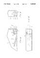
- FIG. 1is a top plan view fragment of a surgical blade remover according to the present invention
- FIG. 2is an end view fragment from one end of the surgical blade remover
- FIG. 3is a section view fragment of the surgical blade remover taken along line 3--3;
- FIG. 4shows a scalpel blade in the process of being removed from a scalpel handle by the blade remover according to the present invention
- FIG. 5shows a conventional surgical scalpel and blade
- FIG. 6is a plan view fragment of an alternative embodiment of the blade remover
- FIG. 7is an end view fragment thereof.
- FIG. 8is a section view fragment thereof.
- a conventional surgical scalpel and scalpel bladewill first be briefly described with reference to FIG. 5.
- scalpel bladesthe present invention may also be used to remove and dispose other surgical implements that are mounted on handles in a similar fashion such as needles, saw blades and the like.
- a typical scalpel blade 1is illustrated in FIG. 5.
- the bladehas a keyed slot 2 with a narrow portion 9 and a wider portion 4 toward the rearward end of the blade.
- a scalpel handlehas a raised portion 5 with grooves 6 on either side.
- the raised portion 5has rounded front and rear faces 7 and 8.
- the raised portionis generally wider than the narrow portion 9 of the blade slot, but fits through the wider portion 4 of the slot to allow attachment and removal of the blade onto the handle, and the grooves 6 are deep enough to permit narrow portion 9 of the blade to engage the grooves 6 and be held on the raised portion.
- the rear face 8engages the rear edge of the blade slot, which prevents the blade from moving along the slot 2 on the grooves 6. Additionally, the rear edge of the blade may abut a surface of the handle to help prevent movement of the blade. Since the blade is somewhat wider than the handle, the edges of the blade project beyond the handle when the blade has been attached.
- the present inventiontherefore provides an improved device for removing of a blade from the handle.
- a preferred embodiment of the present inventionis shown generally in FIG. 1.
- the present inventionincludes a container 10 generally comprising an enclosed polyhedral container, such as shown in U.S. Pat. No. 4,318,473.
- the container 10is used for storing used surgical sharps, such as scalpel blades or suture needles, for disposal.
- the containerhas a hinged lid which may be closed and securely fastened for disposal.
- the lidmay be fastened closed by a snap feature or any other means known in the art. It should be understood that the discussion herein and the depiction in the drawing figures of the precise shape and dimensions of the container, as well as the precise means by which the lid is securely fastened, are illustrative only and are not essential to the present invention.
- the containermay be formed of molded plastic.
- the precise material used to form the containeris not essential to the present invention, provided that the material is of sufficient strength and thickness to prevent the blades or needles stored inside from penetrating the container walls.
- the lidmay be kept open, so that medical personnel can view the contents of the box in order to keep count of the number of blades or other sharps that have been used and removed.
- the floor or bottom of the boxmay be provided with a magnetic surface so that blades and other metal sharps placed into the container will not accidentally fall out of it.
- the bottom of the boxmay be provided with a rubber or foam surface, for the same reason.
- the blade removercomprises an aperture or opening 14 disposed in a wall of the container, into which a surgical scalpel and blade can be inserted in order to remove the blade.
- the aperture 14is defined by a first guide wall 16 and a second guide wall 12 opposite the guide wall 16.
- the guide wall 16may be formed so that the aperture tapers slightly, so that aperture 14 becomes narrower as it progresses into the container.
- the guide wall 16may be formed at an angle of 10 degrees from parallel, relative to the opposing wall 12 of the container.
- the guide wall 16 and the walls of the containerguide the scalpel into the interior of the container.
- a short distance into the aperture 14 along the guide wall 16i.e., at a distance from the exterior wall of the container
- shoulders 18 and 20are disposed projecting from guide wall 16.
- this distanceis 0.470 inches, the precise distance may be varied without affecting the scope or spirit of the present invention.
- the dimensions of the blade remover, including this distanceshould preferably be such that a single blade remover can accommodate blades and handles of many different sizes and shapes.
- Shoulders 18 and 20may be better understood with reference to FIGS. 2 and 3. Shoulders 18 and 20 are substantially rectangular and project from guide wall 16 partially into the path of a scalpel inserted into aperture 14. However, the dimensions of shoulders 18 and 20 are such that sufficient space exists between the lower ends of shoulders 18 and 20 and the aperture wall 12 to permit the blade of a scalpel to pass therebetween. Additionally, the shoulders 18 and 20 are sufficiently narrow, and are disposed sufficiently far apart, to permit the front end of the handle portion of a scalpel to pass through the space created between the shoulders.
- the shoulders 18 and 20may be disposed on the guide wall 16 such that, when viewed from the perspective of FIG. 1 or FIG. 3, the two shoulders are located at slightly different distances from the external entrance of the aperture 14, so that the blade remover can accommodate surgical handles and blades of varying sizes and shapes, and having asymmetrical shapes, such as a typical scalpel blade illustrated in FIG. 5.
- An angled blade deflector 24is provided extending from aperture wall 12 into the interior of the container 10. In a preferred embodiment, this blade deflector 24 extends at an angle of about 13 degrees from the container wall 12, so that the blade deflector 24 forms a ramp rising from the portion of wall 12 opposite the shoulders 18 and 20 into the interior of the container 10.
- a third shoulder 22is provided on the aperture wall 12, at the external entrance of the aperture 14. Shoulder 22 comprises a substantially rectangular portion projecting from aperture wall 12 partially into the aperture 14.
- a scalpel having an attached bladeis inserted into aperture 14, with the raised portion of the scalpel (the portion onto which the blade slot fits when it is attached) facing aperture wall 12.
- the scalpelis pushed forward into the aperture 14, so that the scalpel blade passes through the space between the shoulders 18 and 20 and the aperture wall 12, and the handle of the scalpel passes through the space between shoulder 18 and shoulder 20.
- the scalpel bladepasses the shoulders 18 and 20, it begins to slide along the ramp formed by the blade deflector 24.
- the angle of the ramppushes the blade and handle of the scalpel at an angle off-set from the direction of insertion, as the scalpel is pushed further into aperture 14.
- the scalpelAs the forward end of the scalpel travels along the incline of the ramp of the blade deflector 24, the scalpel is caused to move generally in an upward direction of the arrows 3 in FIG. 1, until the rearward portion of the blade extending beyond the handle contacts the shoulders 18 and 20.
- the shoulders 18 and 20prevent the rearward portion of the blade from moving further upward as the scalpel moves further along the incline of the blade deflector 24.
- the handle of the scalpelis narrow enough to fit between the shoulders 18 and 20, this handle continues to move upward while the blade is held against this movement by the shoulders 18 and 20.
- the shoulders 18 and 20cause the rearward portion of the blade to separate slightly from the handle. This separation increases as the scalpel is inserted further into aperture 14 and the forward end of the blade moves further along the incline of blade remover 24, which causes the handle to move further in direction 3 between the two shoulders 18 and 20.
- the bending force applied to the forward end of the bladewill deform the blade within its elastic limits, causing the rearward portion of the blade to bend away from and separate even further from the handle, until the rearward portion of the slot has disengaged from the rear face 8 of the raised portion.
- the scalpel handlemay be removed from the blade remover by pulling it out of aperture 14. While the scalpel handle is being pulled out of aperture 14, the rearward edge of the blade, which is no longer in secure frictional contact with the handle, will come into contact with shoulder 22, which will hold the blade against the withdrawing action of the scalpel. As the handle is then pulled further from the blade remover, the withdrawing action causes the handle to slide against the blade which is being held in place by the shoulder 22.
- This sliding motioncauses the slot of the blade to slide along the groove on the raised portion of the handle.
- the pulling of the handle from the aperture 14 while the rearward portion of the blade is held in place by the shoulder 22 and the forward end of the blade is bent within its elastic limits around the handlecreates the combination of forces necessary to remove the blade from the handle.
- This sliding motioncontinues as the handle is further withdrawn from the aperture 14 until the slot of the blade has been completely freed of the groove on the raised portion of the handle.
- the bladewill have been completely disengaged from the handle and will remain in aperture 14. Thereafter, the loose blade can be transferred to the interior of the container 10 by simply tilting the container 10 until the loose blade is free of the shoulders 18 and 20 and the ramp 24.
- FIG. 4depicts a conventional scalpel, indicated generally by reference numeral 30, which has been fully inserted into the blade remover of the present invention.
- the forward end of scalpel blade 1has been elastically bent by the incline of the blade remover 24, and the shoulders 18 and 20 have caused the rearward portion of the blade 1 to separate from the handle, so that the rear edge of the blade is engaged in contact with shoulder 22.
- Withdrawal of the scalpel along the line indicated by arrow 34will cause the blade 1, held within the blade remover by shoulder 22, to slide along the raised portion until it disengages from the scalpel handle.
- the optimal dimensions of the various parts of the blade remover as herein describedshould be such that insertion of the scalpel into aperture 14 causes the rearward edge of the blade to engage shoulder 22 at approximately the precise moment that the rear edge of the slot has become completely disengaged from the rear face 8 of the raised portion of the handle. This insures that during withdrawal of the scalpel, when the separation between the rearward portion of the blade and the handle becomes smaller as the torque created by the shoulders 18 and 20 and the blade deflector 24 is lessened, the rear edge of the slot is not permitted to re-engage the rear face 8 before the rear edge of the blade can engage the shoulder 22, as would occur if the distance between the shoulder 22 and the base of the blade deflector 24 is too large. In a preferred embodiment, satisfactory performance is achieved by disposing the base of the blade deflector 24 approximately one-half inch from the shoulder 22 along wall 12.
- the blade remover as described abovetherefore permits medical personnel to remove a blade from a scalpel or surgical knife by simply inserting the blade end of the scalpel into aperture 14 until the blade deflector 24 and shoulders 18 and 20 bend the blade, thereby deforming it within its elastic limits so that shoulder 22 engages the rearward edge of the blade, and then withdrawing the scalpel while the shoulder 22 holds the blade in place against the withdrawing action.
- the entire processis performed quickly and easily by simply inserting the blade into the apparatus on a straight line and pushing it forward, and then removing the handle on the same straight line. By performing this simple motion, the blade is removed from the handle and remains in the interior of the container 10, for easy disposal.
- a shoulder ramp 32may be provided on one edge of the aperture 14, to facilitate proper insertion of the scalpel blade into the surgical blade remover.
- the shoulder ramp 32may comprise a projecting portion angled as shown in FIG. 8, so that a surgical blade and scalpel improperly inserted into aperture 14 will slide along the angled surface and into proper alignment in the aperture 14 relative to the shoulders 18 and 20.
Landscapes
- Health & Medical Sciences (AREA)
- Life Sciences & Earth Sciences (AREA)
- Surgery (AREA)
- Heart & Thoracic Surgery (AREA)
- Engineering & Computer Science (AREA)
- Biomedical Technology (AREA)
- Nuclear Medicine, Radiotherapy & Molecular Imaging (AREA)
- Medical Informatics (AREA)
- Molecular Biology (AREA)
- Animal Behavior & Ethology (AREA)
- General Health & Medical Sciences (AREA)
- Public Health (AREA)
- Veterinary Medicine (AREA)
- Surgical Instruments (AREA)
Abstract
Description
Claims (11)
Priority Applications (1)
| Application Number | Priority Date | Filing Date | Title |
|---|---|---|---|
| US08/138,415US5449068A (en) | 1993-10-18 | 1993-10-18 | Surgical blade remover |
Applications Claiming Priority (1)
| Application Number | Priority Date | Filing Date | Title |
|---|---|---|---|
| US08/138,415US5449068A (en) | 1993-10-18 | 1993-10-18 | Surgical blade remover |
Publications (1)
| Publication Number | Publication Date |
|---|---|
| US5449068Atrue US5449068A (en) | 1995-09-12 |
Family
ID=22481901
Family Applications (1)
| Application Number | Title | Priority Date | Filing Date |
|---|---|---|---|
| US08/138,415Expired - LifetimeUS5449068A (en) | 1993-10-18 | 1993-10-18 | Surgical blade remover |
Country Status (1)
| Country | Link |
|---|---|
| US (1) | US5449068A (en) |
Cited By (44)
| Publication number | Priority date | Publication date | Assignee | Title |
|---|---|---|---|---|
| WO1997026834A1 (en)* | 1996-01-24 | 1997-07-31 | Kimberly-Clark Worldwide, Inc. | Medical sharps and blades removal and containment structure |
| US5875533A (en)* | 1994-09-09 | 1999-03-02 | Qlicksmart Pty Ltd. | Scalpel blade remover |
| FR2773465A1 (en)* | 1998-01-13 | 1999-07-16 | Nestor Basquin | Used scalpel blade and syringe or catheter needle remover - comprises container top with apertures in upper surface shaped to take off blades and needles and to receive larger items of waste. |
| US5938027A (en)* | 1997-12-08 | 1999-08-17 | Stony Brook Surgical Innovations, Inc. | Surgical blade system |
| GB2338230A (en)* | 1996-01-24 | 1999-12-15 | Kimberly Clark Co | Removal and containment device for medical sharps |
| US6216868B1 (en) | 1999-07-09 | 2001-04-17 | Stonybrook Surgical Innovations Inc. | Surgical blade system |
| US6626925B2 (en) | 2001-03-29 | 2003-09-30 | Becton Dickinson And Company | Shielded surgical scalpel |
| USD481129S1 (en) | 2003-01-29 | 2003-10-21 | Becton Dickinson And Company | Blade holder |
| USD482122S1 (en) | 2002-12-27 | 2003-11-11 | Becton Dickinson And Company | Handle |
| USD482449S1 (en) | 2002-12-27 | 2003-11-18 | Becton Dickinson And Company | Handle |
| USD482788S1 (en) | 2002-12-27 | 2003-11-25 | Becton Dickinson And Company | Blade carrier |
| USD483124S1 (en) | 2002-12-27 | 2003-12-02 | Becton Dickinson And Company | Handle |
| USD483123S1 (en) | 2002-12-27 | 2003-12-02 | Becton Dickinson And Company | Blade carrier |
| USD486232S1 (en) | 2002-12-27 | 2004-02-03 | Becton Dickinson And Company | Handle |
| USD489457S1 (en) | 2002-12-27 | 2004-05-04 | Becton Dickinson And Company | Handle |
| USD490153S1 (en) | 2002-12-27 | 2004-05-18 | Becton Dickinson And Company | Blade carrier |
| USD490154S1 (en) | 2002-12-27 | 2004-05-18 | Becton, Dickinson And Company | Handle |
| US20040111853A1 (en)* | 2002-11-12 | 2004-06-17 | Mike Hoftman | Scalpel blade remover and sharps container |
| USD502542S1 (en) | 2002-12-27 | 2005-03-01 | Becton Dickinson And Company | Handle |
| US7119689B2 (en) | 2003-09-19 | 2006-10-10 | Vesta Medical, Llc | System and method for sorting medical waste for disposal |
| US20070039844A1 (en)* | 2005-08-22 | 2007-02-22 | Zyzelewski Mark E | Sharps Container with Integrated Blade Disarming Device |
| US7275645B2 (en) | 2003-09-19 | 2007-10-02 | Vesta Medical, Llc | Handheld medical waste sorting device |
| US7303081B2 (en) | 2003-09-19 | 2007-12-04 | Vesta Medical, Llc | Handheld medical waste sorting method |
| US7311207B2 (en) | 2003-09-19 | 2007-12-25 | Vesta Medical, Llc | System for sorting discarded and spent pharmaceutical items |
| US7318529B2 (en) | 2003-09-19 | 2008-01-15 | Vest Medical, Llc | Method for sorting discarded and spent pharmaceutical items |
| US20080300612A1 (en)* | 2007-05-21 | 2008-12-04 | Riza Erol D | Cutting blade storage apparatus |
| US7562025B2 (en) | 2003-09-19 | 2009-07-14 | Vesta Medical, Llc | Waste sorting system with query function, and method thereof |
| US7660724B2 (en) | 2003-09-19 | 2010-02-09 | Vesta Medical, Llc | Waste sorting system utilizing removable liners |
| US7970722B1 (en) | 1999-11-08 | 2011-06-28 | Aloft Media, Llc | System, method and computer program product for a collaborative decision platform |
| USRE42507E1 (en) | 1993-12-08 | 2011-06-28 | Aspen Surgical Products, Inc. | Surgical scalpel |
| US8195328B2 (en) | 2003-09-19 | 2012-06-05 | Vesta Medical, Llc | Combination disposal and dispensing apparatus and method |
| WO2013016284A1 (en)* | 2011-07-22 | 2013-01-31 | Ansell Limited | Sharps container for removing and containing blades from round scalpel handles |
| US8752700B1 (en)* | 2003-11-12 | 2014-06-17 | Moshe Mike Hoftman | Sharps container with blade remover, needle unsheather, latch and security alignment extensions |
| USD721821S1 (en) | 2013-03-14 | 2015-01-27 | Aspen Surgical Products, Inc. | Needle counter |
| US20150047170A1 (en)* | 2012-03-26 | 2015-02-19 | Qlicksmart Pty Ltd | Universal scalpel blade remover |
| USD745155S1 (en) | 2013-03-14 | 2015-12-08 | Aspen Surgical Products, Inc. | Blade disarmer |
| FR3037046A1 (en)* | 2015-06-04 | 2016-12-09 | Mure Et Peyrot | BOX WITH BLADE EXTRACTOR |
| US9622773B2 (en) | 2012-03-19 | 2017-04-18 | Aspen Surgical Products, Inc. | Side activated safety scalpel for left and right hand users with blade removal system |
| USD813390S1 (en) | 2016-01-15 | 2018-03-20 | Aspen Surgical Products, Inc. | Surgical scalpel blade attachment |
| US10064647B2 (en) | 2015-10-09 | 2018-09-04 | Aspen Surgical Products, Inc. | Scalpel blade remover |
| US10299825B2 (en) | 2014-10-03 | 2019-05-28 | Aspen Surgical Products, Inc. | Sharps blade applicator and storage device |
| US11278310B2 (en) | 2016-03-21 | 2022-03-22 | Aspen Surgical Products, Inc. | Safety scalpel handle |
| WO2024030015A1 (en)* | 2022-08-01 | 2024-02-08 | Tay Keng Kiong | A sharps dislodger |
| US12016588B2 (en) | 2018-04-11 | 2024-06-25 | University Of Virginia Patent Foundation | Surgical incision apparatus and related methods thereof |
Citations (9)
| Publication number | Priority date | Publication date | Assignee | Title |
|---|---|---|---|---|
| US3172316A (en)* | 1961-02-13 | 1965-03-09 | Herman R Grieshaber | Blade-removing tool |
| US4120397A (en)* | 1977-10-04 | 1978-10-17 | Richard-Allan Medical Industries, Inc. | Unit for accommodating disposable bladelike articles |
| US4180162A (en)* | 1978-12-04 | 1979-12-25 | Magney Herbert C | Combination dispenser-disposal cartridge for a surgical blade |
| US4270416A (en)* | 1978-04-21 | 1981-06-02 | Jermed Limited | Scalpel blade extractor |
| US4318473A (en)* | 1980-12-15 | 1982-03-09 | Sandel Dan S | Surgical blade removal and disposal device |
| US4395807A (en)* | 1981-08-05 | 1983-08-02 | Instranetics, Inc. | Surgical blade remover |
| US4746016A (en)* | 1987-03-26 | 1988-05-24 | The Research Foundation Of State University Of New York | Blade removal and/or mounting mechanism and dispenser, extractor-disposal apparatus including same |
| US4903390A (en)* | 1988-10-03 | 1990-02-27 | Vir Engineering, Inc. | Scalpel blade remover and blade storage apparatus |
| US5088173A (en)* | 1989-04-26 | 1992-02-18 | Kromer Martin W | One-time-use precision-blade-bending scalpel blade remover-receptacle |
- 1993
- 1993-10-18USUS08/138,415patent/US5449068A/ennot_activeExpired - Lifetime
Patent Citations (9)
| Publication number | Priority date | Publication date | Assignee | Title |
|---|---|---|---|---|
| US3172316A (en)* | 1961-02-13 | 1965-03-09 | Herman R Grieshaber | Blade-removing tool |
| US4120397A (en)* | 1977-10-04 | 1978-10-17 | Richard-Allan Medical Industries, Inc. | Unit for accommodating disposable bladelike articles |
| US4270416A (en)* | 1978-04-21 | 1981-06-02 | Jermed Limited | Scalpel blade extractor |
| US4180162A (en)* | 1978-12-04 | 1979-12-25 | Magney Herbert C | Combination dispenser-disposal cartridge for a surgical blade |
| US4318473A (en)* | 1980-12-15 | 1982-03-09 | Sandel Dan S | Surgical blade removal and disposal device |
| US4395807A (en)* | 1981-08-05 | 1983-08-02 | Instranetics, Inc. | Surgical blade remover |
| US4746016A (en)* | 1987-03-26 | 1988-05-24 | The Research Foundation Of State University Of New York | Blade removal and/or mounting mechanism and dispenser, extractor-disposal apparatus including same |
| US4903390A (en)* | 1988-10-03 | 1990-02-27 | Vir Engineering, Inc. | Scalpel blade remover and blade storage apparatus |
| US5088173A (en)* | 1989-04-26 | 1992-02-18 | Kromer Martin W | One-time-use precision-blade-bending scalpel blade remover-receptacle |
Non-Patent Citations (2)
| Title |
|---|
| Devon Sharps Counting and Disposal Systems Brochure No Date.* |
| Devon Sharps Counting and Disposal Systems Brochure-No Date. |
Cited By (80)
| Publication number | Priority date | Publication date | Assignee | Title |
|---|---|---|---|---|
| USRE42507E1 (en) | 1993-12-08 | 2011-06-28 | Aspen Surgical Products, Inc. | Surgical scalpel |
| US5875533A (en)* | 1994-09-09 | 1999-03-02 | Qlicksmart Pty Ltd. | Scalpel blade remover |
| GB2325461B (en)* | 1996-01-24 | 2000-03-29 | Kimberly Clark Co | Medical sharps and blades removal and containment structure |
| GB2338231B (en)* | 1996-01-24 | 2000-05-10 | Kimberly Clark Co | Medical sharps and blades removal and containment structure |
| AU706994B2 (en)* | 1996-01-24 | 1999-07-01 | Kimberly-Clark Worldwide, Inc. | Medical sharps and blades removal and containment structure |
| GB2325461A (en)* | 1996-01-24 | 1998-11-25 | Kimberly Clark Co | Medical sharps and blades removal and containment structure |
| US5894925A (en)* | 1996-01-24 | 1999-04-20 | Kimberly-Clark Worldwide, Inc. | Medical sharps blade removal and containment structure |
| GB2338230A (en)* | 1996-01-24 | 1999-12-15 | Kimberly Clark Co | Removal and containment device for medical sharps |
| GB2338231A (en)* | 1996-01-24 | 1999-12-15 | Kimberly Clark Co | Removal and containment device for medical sharps |
| GB2338230B (en)* | 1996-01-24 | 2000-03-08 | Kimberly Clark Co | Medical sharps and blades removal and containment structure |
| WO1997026834A1 (en)* | 1996-01-24 | 1997-07-31 | Kimberly-Clark Worldwide, Inc. | Medical sharps and blades removal and containment structure |
| US5938027A (en)* | 1997-12-08 | 1999-08-17 | Stony Brook Surgical Innovations, Inc. | Surgical blade system |
| FR2773465A1 (en)* | 1998-01-13 | 1999-07-16 | Nestor Basquin | Used scalpel blade and syringe or catheter needle remover - comprises container top with apertures in upper surface shaped to take off blades and needles and to receive larger items of waste. |
| US6216868B1 (en) | 1999-07-09 | 2001-04-17 | Stonybrook Surgical Innovations Inc. | Surgical blade system |
| US7970722B1 (en) | 1999-11-08 | 2011-06-28 | Aloft Media, Llc | System, method and computer program product for a collaborative decision platform |
| US8005777B1 (en) | 1999-11-08 | 2011-08-23 | Aloft Media, Llc | System, method and computer program product for a collaborative decision platform |
| US8160988B1 (en) | 1999-11-08 | 2012-04-17 | Aloft Media, Llc | System, method and computer program product for a collaborative decision platform |
| US6626925B2 (en) | 2001-03-29 | 2003-09-30 | Becton Dickinson And Company | Shielded surgical scalpel |
| US8596453B2 (en)* | 2002-11-12 | 2013-12-03 | Mike Hoftman | Scalpel blade remover and sharps container |
| US20040111853A1 (en)* | 2002-11-12 | 2004-06-17 | Mike Hoftman | Scalpel blade remover and sharps container |
| USD489457S1 (en) | 2002-12-27 | 2004-05-04 | Becton Dickinson And Company | Handle |
| USD486232S1 (en) | 2002-12-27 | 2004-02-03 | Becton Dickinson And Company | Handle |
| USD490153S1 (en) | 2002-12-27 | 2004-05-18 | Becton Dickinson And Company | Blade carrier |
| USD490154S1 (en) | 2002-12-27 | 2004-05-18 | Becton, Dickinson And Company | Handle |
| USD483123S1 (en) | 2002-12-27 | 2003-12-02 | Becton Dickinson And Company | Blade carrier |
| USD502542S1 (en) | 2002-12-27 | 2005-03-01 | Becton Dickinson And Company | Handle |
| USD483124S1 (en) | 2002-12-27 | 2003-12-02 | Becton Dickinson And Company | Handle |
| USD482788S1 (en) | 2002-12-27 | 2003-11-25 | Becton Dickinson And Company | Blade carrier |
| USD482449S1 (en) | 2002-12-27 | 2003-11-18 | Becton Dickinson And Company | Handle |
| USD482122S1 (en) | 2002-12-27 | 2003-11-11 | Becton Dickinson And Company | Handle |
| USD481129S1 (en) | 2003-01-29 | 2003-10-21 | Becton Dickinson And Company | Blade holder |
| US7454358B2 (en) | 2003-09-19 | 2008-11-18 | Vesta Medical, Llc | Waste scanning method |
| US8195328B2 (en) | 2003-09-19 | 2012-06-05 | Vesta Medical, Llc | Combination disposal and dispensing apparatus and method |
| US7303082B2 (en) | 2003-09-19 | 2007-12-04 | Vesta Medical, Llc | Medical waste sorting system with container identification |
| US7303080B2 (en) | 2003-09-19 | 2007-12-04 | Vesta Medical, Llc | Waste sensor for a disposable container |
| US7303081B2 (en) | 2003-09-19 | 2007-12-04 | Vesta Medical, Llc | Handheld medical waste sorting method |
| US7311207B2 (en) | 2003-09-19 | 2007-12-25 | Vesta Medical, Llc | System for sorting discarded and spent pharmaceutical items |
| US7318529B2 (en) | 2003-09-19 | 2008-01-15 | Vest Medical, Llc | Method for sorting discarded and spent pharmaceutical items |
| US7341147B2 (en) | 2003-09-19 | 2008-03-11 | Vesta Medical, Llc | Disposable container for use in a waste sorting system |
| US7383195B2 (en) | 2003-09-19 | 2008-06-03 | Vesta Medical, Llc | Methods of sorting waste |
| US7275645B2 (en) | 2003-09-19 | 2007-10-02 | Vesta Medical, Llc | Handheld medical waste sorting device |
| US8868434B2 (en) | 2003-09-19 | 2014-10-21 | Carefusion 303, Inc. | Waste sorting and disposal method using labels |
| US7483837B2 (en) | 2003-09-19 | 2009-01-27 | Vesta Medical, Llc | Waste sensing system |
| US7487100B2 (en) | 2003-09-19 | 2009-02-03 | Vesta Medical, Llc | Method of sorting regulated drug waste |
| US7533029B2 (en) | 2003-09-19 | 2009-05-12 | Vesta Medical, Llc | Waste sorting system for rendering drugs non-recoverable |
| US7533028B2 (en) | 2003-09-19 | 2009-05-12 | Vesta Medical, Llc | Waste sorting method for rendering drugs non-recoverable |
| US7562025B2 (en) | 2003-09-19 | 2009-07-14 | Vesta Medical, Llc | Waste sorting system with query function, and method thereof |
| US7565299B2 (en) | 2003-09-19 | 2009-07-21 | Vesta Medical, Llc | Waste sorting and tracking system and method |
| US7617113B2 (en) | 2003-09-19 | 2009-11-10 | Vesta Medical, Llc | Medical waste sorting method |
| US7620559B2 (en) | 2003-09-19 | 2009-11-17 | Vesta Medical, Llc | System for facilitating medical waste disposal |
| US7660724B2 (en) | 2003-09-19 | 2010-02-09 | Vesta Medical, Llc | Waste sorting system utilizing removable liners |
| US7664656B2 (en) | 2003-09-19 | 2010-02-16 | Mallett Scott R | Method of sorting waste utilizing removable liners |
| US7119689B2 (en) | 2003-09-19 | 2006-10-10 | Vesta Medical, Llc | System and method for sorting medical waste for disposal |
| US7138918B2 (en) | 2003-09-19 | 2006-11-21 | Vesta Medical, Llc | System for sorting waste |
| US7126480B2 (en) | 2003-09-19 | 2006-10-24 | Vesta Medical, Llc | Waste sorting network |
| US7123150B2 (en) | 2003-09-19 | 2006-10-17 | Vesta Medical, Llc | Waste container identification system |
| US7296688B2 (en) | 2003-09-19 | 2007-11-20 | Vesta Medical, Llc | Apparatus for facilitating medical waste disposal |
| US8204620B2 (en) | 2003-09-19 | 2012-06-19 | Vesta Medical, Llc | Method for combined disposal and dispensing of medical items |
| US8296243B2 (en) | 2003-09-19 | 2012-10-23 | Vesta Medical, Llc | Systems for identifying and categorizing medical waste |
| US8355994B2 (en) | 2003-09-19 | 2013-01-15 | Vesta Medical Llc | Sorting system for composite drugs |
| US8595021B2 (en) | 2003-09-19 | 2013-11-26 | Carefusion 303, Inc. | Methods for identifying and categorizing medical waste |
| US8560460B2 (en) | 2003-09-19 | 2013-10-15 | Carefusion 303, Inc. | Automated waste sorting system |
| US8752700B1 (en)* | 2003-11-12 | 2014-06-17 | Moshe Mike Hoftman | Sharps container with blade remover, needle unsheather, latch and security alignment extensions |
| US20070039844A1 (en)* | 2005-08-22 | 2007-02-22 | Zyzelewski Mark E | Sharps Container with Integrated Blade Disarming Device |
| US20080300612A1 (en)* | 2007-05-21 | 2008-12-04 | Riza Erol D | Cutting blade storage apparatus |
| WO2013016284A1 (en)* | 2011-07-22 | 2013-01-31 | Ansell Limited | Sharps container for removing and containing blades from round scalpel handles |
| US8800766B2 (en) | 2011-07-22 | 2014-08-12 | Ansell Limited | Sharps container for removing and containing blades from round scalpel handles |
| US10292729B2 (en) | 2012-03-19 | 2019-05-21 | Aspen Surgical Products, Inc. | Side activated safety scalpel for left and right hand users with blade removal system |
| US9622773B2 (en) | 2012-03-19 | 2017-04-18 | Aspen Surgical Products, Inc. | Side activated safety scalpel for left and right hand users with blade removal system |
| US9504487B2 (en)* | 2012-03-26 | 2016-11-29 | Qlicksmart Pty Ltd | Universal scalpel blade remover |
| US20150047170A1 (en)* | 2012-03-26 | 2015-02-19 | Qlicksmart Pty Ltd | Universal scalpel blade remover |
| USD745155S1 (en) | 2013-03-14 | 2015-12-08 | Aspen Surgical Products, Inc. | Blade disarmer |
| USD721821S1 (en) | 2013-03-14 | 2015-01-27 | Aspen Surgical Products, Inc. | Needle counter |
| US10299825B2 (en) | 2014-10-03 | 2019-05-28 | Aspen Surgical Products, Inc. | Sharps blade applicator and storage device |
| FR3037046A1 (en)* | 2015-06-04 | 2016-12-09 | Mure Et Peyrot | BOX WITH BLADE EXTRACTOR |
| US10064647B2 (en) | 2015-10-09 | 2018-09-04 | Aspen Surgical Products, Inc. | Scalpel blade remover |
| USD813390S1 (en) | 2016-01-15 | 2018-03-20 | Aspen Surgical Products, Inc. | Surgical scalpel blade attachment |
| US11278310B2 (en) | 2016-03-21 | 2022-03-22 | Aspen Surgical Products, Inc. | Safety scalpel handle |
| US12016588B2 (en) | 2018-04-11 | 2024-06-25 | University Of Virginia Patent Foundation | Surgical incision apparatus and related methods thereof |
| WO2024030015A1 (en)* | 2022-08-01 | 2024-02-08 | Tay Keng Kiong | A sharps dislodger |
Similar Documents
| Publication | Publication Date | Title |
|---|---|---|
| US5449068A (en) | Surgical blade remover | |
| US4746016A (en) | Blade removal and/or mounting mechanism and dispenser, extractor-disposal apparatus including same | |
| US4730376A (en) | Blade removal apparatus for changeable blade scalpel | |
| US6216868B1 (en) | Surgical blade system | |
| US5938027A (en) | Surgical blade system | |
| US4318473A (en) | Surgical blade removal and disposal device | |
| US7155795B2 (en) | Method for mounting a surgical blade onto a scalpel and for subsequently removing the blade from the scalpel using a package incorporating a pivotable flap | |
| US4106620A (en) | Surgical blade dispenser | |
| US4903390A (en) | Scalpel blade remover and blade storage apparatus | |
| JP4038238B2 (en) | Knife with retractable blade | |
| US5088173A (en) | One-time-use precision-blade-bending scalpel blade remover-receptacle | |
| US5699908A (en) | Scalpel blade removal and storage apparatus | |
| JP3604394B2 (en) | Knife removal tool | |
| EP0948937A2 (en) | Surgical scalpel | |
| US20070039844A1 (en) | Sharps Container with Integrated Blade Disarming Device | |
| EP2682070B1 (en) | Passing tray surgical instruments | |
| NZ538442A (en) | Surgical scalpel with retractable guard | |
| EP1622533B1 (en) | Scalpel blade remover | |
| US5875532A (en) | Surgical instrument blade injector and mounting method | |
| US9717521B2 (en) | Surgical knife and tools adapted for simplified blade removal | |
| US5894925A (en) | Medical sharps blade removal and containment structure | |
| US5163553A (en) | Scalpel blade extractor and disposal unit | |
| EP0034949A2 (en) | Scalpel blade remover and collector | |
| WO1997026834A9 (en) | Medical sharps and blades removal and containment structure | |
| US5729879A (en) | Surgical blade removal and disposal device |
Legal Events
| Date | Code | Title | Description |
|---|---|---|---|
| AS | Assignment | Owner name:DEVON INDUSTRIES, INC., CALIFORNIA Free format text:ASSIGNMENT OF ASSIGNORS INTEREST;ASSIGNOR:GHARIBIAN, NOEL;REEL/FRAME:006739/0965 Effective date:19931013 | |
| STCF | Information on status: patent grant | Free format text:PATENTED CASE | |
| AS | Assignment | Owner name:CHEMICAL BANK (AS COLLATERAL AGENT), NEW YORK Free format text:SECURITY INTEREST;ASSIGNOR:DEVON INDUSTRIES, INC.;REEL/FRAME:007881/0730 Effective date:19960229 | |
| FEPP | Fee payment procedure | Free format text:PAT HLDR NO LONGER CLAIMS SMALL ENT STAT AS SMALL BUSINESS (ORIGINAL EVENT CODE: LSM2); ENTITY STATUS OF PATENT OWNER: LARGE ENTITY | |
| FPAY | Fee payment | Year of fee payment:4 | |
| FEPP | Fee payment procedure | Free format text:PAYER NUMBER DE-ASSIGNED (ORIGINAL EVENT CODE: RMPN); ENTITY STATUS OF PATENT OWNER: LARGE ENTITY Free format text:PAYOR NUMBER ASSIGNED (ORIGINAL EVENT CODE: ASPN); ENTITY STATUS OF PATENT OWNER: LARGE ENTITY | |
| FPAY | Fee payment | Year of fee payment:8 | |
| FPAY | Fee payment | Year of fee payment:12 |