US5448989A - Medical instrument shaft capable of positive and non-positive linking of segments - Google Patents
Medical instrument shaft capable of positive and non-positive linking of segmentsDownload PDFInfo
- Publication number
- US5448989A US5448989AUS08/200,082US20008294AUS5448989AUS 5448989 AUS5448989 AUS 5448989AUS 20008294 AUS20008294 AUS 20008294AUS 5448989 AUS5448989 AUS 5448989A
- Authority
- US
- United States
- Prior art keywords
- segments
- group
- shaft
- distal
- segment
- Prior art date
- Legal status (The legal status is an assumption and is not a legal conclusion. Google has not performed a legal analysis and makes no representation as to the accuracy of the status listed.)
- Expired - Fee Related
Links
- 238000012327Endoscopic diagnosisMethods0.000description1
- 238000013276bronchoscopyMethods0.000description1
- 238000010276constructionMethods0.000description1
- 230000000694effectsEffects0.000description1
- 238000001839endoscopyMethods0.000description1
- 238000003780insertionMethods0.000description1
- 230000037431insertionEffects0.000description1
- 238000000034methodMethods0.000description1
- 238000012986modificationMethods0.000description1
- 230000004048modificationEffects0.000description1
- 239000013049sedimentSubstances0.000description1
- 238000007493shaping processMethods0.000description1
- 239000000725suspensionSubstances0.000description1
- 238000002560therapeutic procedureMethods0.000description1
Images


Classifications
- A—HUMAN NECESSITIES
- A61—MEDICAL OR VETERINARY SCIENCE; HYGIENE
- A61B—DIAGNOSIS; SURGERY; IDENTIFICATION
- A61B1/00—Instruments for performing medical examinations of the interior of cavities or tubes of the body by visual or photographical inspection, e.g. endoscopes; Illuminating arrangements therefor
- A61B1/005—Flexible endoscopes
- A61B1/0051—Flexible endoscopes with controlled bending of insertion part
- A61B1/0055—Constructional details of insertion parts, e.g. vertebral elements
- A—HUMAN NECESSITIES
- A61—MEDICAL OR VETERINARY SCIENCE; HYGIENE
- A61B—DIAGNOSIS; SURGERY; IDENTIFICATION
- A61B1/00—Instruments for performing medical examinations of the interior of cavities or tubes of the body by visual or photographical inspection, e.g. endoscopes; Illuminating arrangements therefor
- A61B1/005—Flexible endoscopes
- A61B1/0051—Flexible endoscopes with controlled bending of insertion part
- A61B1/0052—Constructional details of control elements, e.g. handles
- A—HUMAN NECESSITIES
- A61—MEDICAL OR VETERINARY SCIENCE; HYGIENE
- A61B—DIAGNOSIS; SURGERY; IDENTIFICATION
- A61B1/00—Instruments for performing medical examinations of the interior of cavities or tubes of the body by visual or photographical inspection, e.g. endoscopes; Illuminating arrangements therefor
- A61B1/005—Flexible endoscopes
- A61B1/0051—Flexible endoscopes with controlled bending of insertion part
- A61B1/0057—Constructional details of force transmission elements, e.g. control wires
- A—HUMAN NECESSITIES
- A61—MEDICAL OR VETERINARY SCIENCE; HYGIENE
- A61B—DIAGNOSIS; SURGERY; IDENTIFICATION
- A61B34/00—Computer-aided surgery; Manipulators or robots specially adapted for use in surgery
- A61B34/70—Manipulators specially adapted for use in surgery
- A61B34/71—Manipulators operated by drive cable mechanisms
- A—HUMAN NECESSITIES
- A61—MEDICAL OR VETERINARY SCIENCE; HYGIENE
- A61B—DIAGNOSIS; SURGERY; IDENTIFICATION
- A61B34/00—Computer-aided surgery; Manipulators or robots specially adapted for use in surgery
- A61B34/30—Surgical robots
- A61B2034/305—Details of wrist mechanisms at distal ends of robotic arms
- A61B2034/306—Wrists with multiple vertebrae
- A—HUMAN NECESSITIES
- A61—MEDICAL OR VETERINARY SCIENCE; HYGIENE
- A61B—DIAGNOSIS; SURGERY; IDENTIFICATION
- A61B34/00—Computer-aided surgery; Manipulators or robots specially adapted for use in surgery
- A61B34/70—Manipulators specially adapted for use in surgery
- A61B34/71—Manipulators operated by drive cable mechanisms
- A61B2034/715—Cable tensioning mechanisms for removing slack
Definitions
- the inventionis based on a shaft for medical instruments, in particular one for guiding instruments into a body cavity.
- a shaft for medical instrumentsin particular one for guiding instruments into a body cavity.
- neighboring segments that are hollow on the inside and form sections of the shaftare adjustable in their position by means of control wires, whereby at least two groups of segments are adjustable independently of one another.
- a thin-walled instrument shaftcan be bent into the desired shape before use and can then, for example, be guided into a body cavity.
- a disadvantage of an instrument of that typeis that it can only be inserted in a limited way, since the position that is set once before the treatment cannot be further altered.
- bendable arrangements of tubes and shafts for use in an endoscopeespecially for example in the area of bronchoscopy
- the arrangement of tubeshas, at least in part, regions of segments that are arranged together in a series and that are movable against each other, whereby for the purpose of setting shaft curvatures, the segments can be moved by means of control wires that are guided into a handle.
- Examples of theseare set forth in DE-GM 69 38 905, U.S. Pat. No. 3,190,286, DE-AS 1 291 437, DE-OS 1 766 209, DE-AS 1 816 973, and DE-OS 1 950 035.
- An object of the inventionis to provide a shaft for medical instruments, particularly, for guiding of instruments into a body cavity, the curvature of which shaft can easily be changed upon introduction into a body cavity and during the examination of a body cavity, and that, in addition, can be set, that is fixed, in a working position in such a way that it can be handled like a rigid shaft.
- the advantage of this solution in accordance with the inventionlies in the fact that the segments of the groups can be adjusted independently of one another.
- the distal part of the shaftcan be set and/or adjusted before and during the use in a body cavity, so that it can always be adapted to existing conditions, while the segments of the proximal part of the shaft can be so strongly tensioned that this part of the shaft is rigid.
- the sediments of the second groupare held together by tensioning wires that are fixed in an advantageous manner in a tensioning device inside the handle of the instrument. Based upon a particular embodiment of these segments, when there is very strong tension on them, they are no longer held in place in the non-positive manner that exists when they are under low tension, but are instead held in place by means of positive locking.
- adjustment devicesare also provided for the segment groups, so that independent adjustment of the two groups can be carried out.
- the adjustment of the individual segmentstakes place by means of control wires that run through the segments.
- two control wiresare provided, which terminate in the associated adjusting devices in the handle.
- the entire shaftcan ultimately be moved in either one or two planes.
- several groups with differing segmentscan be placed in a series one behind the other so that the shaft can be curved in different ways at several sections.
- the handleshould then be equipped with adjusting devices in an appropriate manner. Further advantageous embodiments of the invention are described below.
- FIG. 1is a full view of a shaft according to the invention with an inserted instrument
- FIG. 2is an enlarged partial view of the shaft
- FIGS. 3-6are sections of the shaft taken along lines III--III, IV--IV, V--V, VI--VI, respectively, in FIG. 2;
- FIG. 7is a section of the shaft shown in FIG. 1, partially in section;
- FIG. 8is another section of the shaft shown in FIG. 1, in section;
- FIG. 9shows a tensioning device for shaft segments
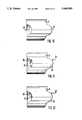
- FIGS. 10-12show different embodiments of shaft segments in side view
- FIG. 13shows a section through the shaft in the region of two adjoining segments
- FIG. 14is a device for tensioning of shaft segments.
- the shaft 1 in accordance with the inventionexhibits over its length three different shaft sections, which are hollow on the inside.
- a handle 7is provided proximally.
- a first, distal segment group 2 made up of individual segments 5represents the first shaft section.
- the segments 5are flexibly linked with one another, and they can be adjusted in their position by means of control wires 10, 11 (see FIGS. 2 and 7) for the purpose of setting shaft curvatures.
- These segments 6differ in their manner of construction from those in the first group 2, concerning which more detail is provided in the description of FIGS. 2, 7, and 8.
- the segments 6 of the second group 3are linked with one another in a non-positive manner, and are tensioned by means of a variably adjustable spring force.
- the segments of both groups 2 and 3are adjustable independently of one another.
- the segments 5, 6are enclosed by a flexible tube as an outer covering.
- the number of groupsdoes not have to be limited to the two that are shown in this embodiment. There is also the possibility of providing several groups of segments, one after the other, that can be adjusted independently of one another, by means of which the shaft can be curved in different ways in three or more sections. Independent of the number of groups, there is attached to the last proximal group a shaft section (in this embodiment shaft part 4), which is rigid in the usual manner and which ends in the handle 7. An instrument 9 for the treatment of the patient can be fed through the interior lumen 8 of the shaft 1. In FIG. 1, such an instrument 9 is indicated by means of its distal end 9a and its handle 9b.
- FIG. 1also shows the handle 7 of the shaft 1.
- This handlecontains the various devices for the setting and adjusting and for tensioning of the segments 5 and 6 of the groups 2 and 3.
- the handle 7is also hollow on the inside in known fashion in order to be able to feed the instrument 9 all the way through.
- the handle 7has an adjusting device 20 which is used to adjust the curvature of the shaft in the region of the first, distal group 2 by means of the control wires 10 and 11.
- a second adjusting device 21is provided (shown by dotted line in FIG. 1), which is used to adjust the curvature of the segments 6 of the second group 3 by means of the control wires 12 and 13.
- handle 7also has a tensioning device 16 for fixing the various positions of the segments 6, which are held together by means of tensioning wires 14 and 15.
- FIGS. 2 through 8 and 10 through 12make clear the embodiments of the segments 5 and 6 which are configured differently.
- the segments 5 of the group 2have at one end semicircular projections 22, and at the other end, matching recesses 23, which lie diametrically opposed to each other, as is shown in section in accordance with FIG. 7 and in FIG. 10. Segments 5 that are configured in that way, can be joined together because of their shape into one shaft section when the two projections 22 of one segment 5 are inserted into the corresponding recesses 23 of an immediately following segment 5.
- Two segments 5are connected with each other in an axially flexible manner by means of lateral connecting pieces 24, which could be pins or rivets for example.
- the last distal segment 5a(as seen in FIG. 2), can be closed off with a flat surface, which forms the distal end of shaft 1.
- the control wires 10 and 11are secured at this last segment 5a, as FIG. 7 makes clear.
- the segments 6 of the second group 3also exhibit at one end semicircular projections 25, and at the other end matching recesses 26, which lie diametrically opposed to each other in accordance with FIGS. 2 and 11.
- the contours of the projections 25 and the recesses 26are in the shape of a wavy line, so that when the segments 6 are joined together, the wave crests 27 of the projections 25 of a segment 6 always interlock in the wave troughs 28 of the recesses 26 of the next sequential segment 6.
- FIG. 12An additional possibility for locking the segments 6 with lock pins is shown in FIG. 12.
- the segments 6are equipped with wavy line-like projections 25 at one end and with lock pins 6c at the other end.
- the lock pins 6c of one segmentcan work in combination with the projections 25 of another segment, in which case, depending on the positioning of the two segments relative to each other, the lock pins lock in one of the wave troughs 28 of the neighboring segment.
- the distally last segment 6a of the second group 3is connected with the proximally first segment 5 of the first group 2 in an axially flexible manner, for example by means of rivets 24.
- the distal end of the rigid shaft part 4is provided with recesses 26 that correspond to those of the segments 6, and depending on the particular embodiment, either exhibits a lock pin or is made in the shape of a wavy line.
- each of the groups that make up the shaft(in this embodiment, groups 2 and 3), can be established in accordance with the conditions of the treatment, that is, in accordance with the insertion site and the nature of the instruments to be inserted, by selecting an appropriate number of segments 5 and/or 6 to be arranged in a series one after the other.
- FIG. 7shows the course of the control wires 10 and 11 of the segments 5, which wires continue in the proximal direction to the adjusting device 20, where they are fastened.
- the control wires 10 and 11run through bores 31 and 32 (see FIGS. 3-5) inside the wall 30 of the segments 5 and 6 of the two groups 2 and 3.
- Adjusting devices of this typeare known, so that they can be made as in DE-OS 1 766 209 or as a simple winch in accordance with U.S. Pat. No. 3,190,286. The same holds true for the adjusting device 21. A description of such an adjusting device is therefore omitted.
- the segments 6 of the second group 3are similarly adjusted by means of control wires 12 and 13, which, in accordance with FIG. 8, are secured at segment 6a and, in a manner analogous to that of control wires 10 and 11 of the segments 5, run through bores of the segments 6 and are guided to the additional adjusting device 21.
- the control wires 12 and 13can, for example, be fed along with the control wires 10 and 11 or along with the tensioning wires 14 and 15 through the appropriate bores 31 and 32 or 33 and 34, so that no additional bores are necessary. If the control wires 12 and 13 are run along with the control wires 10 and 11 through the bores 31 and 32, then the adjustment of the entire shaft 1 in one plane is possible. If the control wires 12 and 13 are run through the bores 33 and 34 (see FIG. 4), the adjustment of the entire shaft 1 in two planes is possible.
- tensioning wires 14 and 15 that run through the bores 33 and 34 of the segments 6are secured proximally in a tensioning device 16, while the distal ends of the tensioning wires 14 and 15 are fastened at segment 6a.
- the tensioning device 16can simply consist of two seats 17 and 18 for a spring 19, for example a coil spring, which as a pressure spring holds the two seats 17 and 18 at a distance from one another.
- the tensioning wires 14 and 15are fed through the two seats 17 and 18 and the spring 19 and are secured at the proximal seat 17.
- the distal seat 18has a threaded region 18a, by means of whose adjustment within a counter-thread 7a in the handle 7, a setting of the tension of the segments 6 takes place by changing the distance between the seats and therefore the spring tension and the tensile force of the tensioning wires 14, 15 that hold the segments 6 together.
- the shaft section that is formed by the segments 6can, for example, be pre-shaped by hand before its introduction into a body cavity, and then by adjusting and increasing the spring pressure by means of the tensioning device 16, a completely rigid shaft section can be attained, while the shaft section formed by the segments 5 remains adjustable.
- the segments 5 of the first group 2can be adjusted with the control wires 10 and 11 for the purpose of setting the necessary shaft curvature.
- the segments 6can take part in the curvature and lock into a new position.
- the possibility of an independent adjustment of the segments 6proves to be advantageous, and this is accomplished by then providing the additional control wires 12 and 13.
- a tensioning of the segments 6 that can be carried out easily and especially quicklycan be attained by means of the tensioning device shown in FIG. 14, in which the same or like-working parts are used as in the tensioning device shown in FIGS. 8 and 9. For this reason, these parts and the tensioning device in FIG. 14 are provided with the same, corresponding reference numerals.
- the tensioning wires 14, 15, which are pre-tensioned by the spring 19,can be drawn so tight that the shaft part made up of the segments 6 becomes practically rigid.
- a disc 16bis provided having an eccentric bore 16c, inside of which the ends of the tensioning wires are fastened, for example by means of a ball 16d.
- Disc 16bis adjusted or turned inside of a housing 16e by means of an adjusting lever 16a that comes out of the handle.
Landscapes
- Health & Medical Sciences (AREA)
- Life Sciences & Earth Sciences (AREA)
- Surgery (AREA)
- Engineering & Computer Science (AREA)
- General Health & Medical Sciences (AREA)
- Veterinary Medicine (AREA)
- Public Health (AREA)
- Animal Behavior & Ethology (AREA)
- Nuclear Medicine, Radiotherapy & Molecular Imaging (AREA)
- Molecular Biology (AREA)
- Biomedical Technology (AREA)
- Heart & Thoracic Surgery (AREA)
- Medical Informatics (AREA)
- Biophysics (AREA)
- Radiology & Medical Imaging (AREA)
- Physics & Mathematics (AREA)
- Pathology (AREA)
- Optics & Photonics (AREA)
- Robotics (AREA)
- Surgical Instruments (AREA)
- Endoscopes (AREA)
Abstract
Description
The invention is based on a shaft for medical instruments, in particular one for guiding instruments into a body cavity. For the purpose of setting shaft curvatures, neighboring segments that are hollow on the inside and form sections of the shaft are adjustable in their position by means of control wires, whereby at least two groups of segments are adjustable independently of one another.
In cases of medical intervention in which an instrument has to be inserted into a body cavity, it is often expedient to guide the instrument by means of a flexible shaft, since in many cases treatment is very difficult otherwise, and the use of flexible instruments causes the patient less pain than the use of rigid instruments. Thus, it is often necessary during endoscopic diagnosis and therapy, for example, to be able to bend at least the distal end of the instruments used in different directions inside the body cavity, and in addition, to be able to leave the shaft in this bent position.
For example, according to DE-AS 1 019 048, it is known that a thin-walled instrument shaft can be bent into the desired shape before use and can then, for example, be guided into a body cavity. However, a disadvantage of an instrument of that type is that it can only be inserted in a limited way, since the position that is set once before the treatment cannot be further altered.
Beyond that, bendable arrangements of tubes and shafts for use in an endoscope, especially for example in the area of bronchoscopy, are known in which the arrangement of tubes has, at least in part, regions of segments that are arranged together in a series and that are movable against each other, whereby for the purpose of setting shaft curvatures, the segments can be moved by means of control wires that are guided into a handle. Examples of these are set forth in DE-GM 69 38 905, U.S. Pat. No. 3,190,286, DE-AS 1 291 437, DE-OS 1 766 209, DE-AS 1 816 973, and DE-OS 1 950 035. In the case of DE-AS 1 816 973, the individual segments of the shaft are linked with one another by means of forks that interlock when the components are joined together. A solution of that type proves to be disadvantageous, since the forks of the segments can easily break or become deformed.
These solutions can be used with varying degrees of success for endoscopy, but they all have the disadvantage that when they are in the distorted state, that is when the curvature of the distal end of the shaft has been established and manipulation of instruments is to be undertaken in the body cavity, no real rigidity of the shaft can be attained, and, due to the unavoidable effects of forces on the shaft from the instrument that has been guided into position, the shaft can easily deviate from the desired position.
With these shafts the characteristics of a rigid shaft cannot be attained, while pre-curved shafts, such as those known from DE-AS 1 019 048, can be used only in a limited manner since they retain during use the shape that was set ahead of time. For that reason, the solution in accordance with DE-OS 1 766 209, in which the groups composed of individual segments can be moved independently of each other by means of wires, is better overall. However, the position that is set cannot be fixed with this solution.
An object of the invention is to provide a shaft for medical instruments, particularly, for guiding of instruments into a body cavity, the curvature of which shaft can easily be changed upon introduction into a body cavity and during the examination of a body cavity, and that, in addition, can be set, that is fixed, in a working position in such a way that it can be handled like a rigid shaft.
This object is achieved in accordance with the invention by providing in the shaft mentioned in the Field of the Invention, the segments of a first distal group, flexibly linked with each other, the proximally adjoining segments of a second group being linked in a non-positive manner and being tensioned by means of a variably adjustable spring force.
The advantage of this solution in accordance with the invention lies in the fact that the segments of the groups can be adjusted independently of one another. In addition, the distal part of the shaft can be set and/or adjusted before and during the use in a body cavity, so that it can always be adapted to existing conditions, while the segments of the proximal part of the shaft can be so strongly tensioned that this part of the shaft is rigid.
Furthermore, the sediments of the second group are held together by tensioning wires that are fixed in an advantageous manner in a tensioning device inside the handle of the instrument. Based upon a particular embodiment of these segments, when there is very strong tension on them, they are no longer held in place in the non-positive manner that exists when they are under low tension, but are instead held in place by means of positive locking.
In addition to the tensioning device inside the handle, adjustment devices are also provided for the segment groups, so that independent adjustment of the two groups can be carried out. The adjustment of the individual segments takes place by means of control wires that run through the segments. For each of the two groups, two control wires are provided, which terminate in the associated adjusting devices in the handle. Depending on the arrangement of the control wires within the segments of the two groups, the entire shaft can ultimately be moved in either one or two planes. In addition, several groups with differing segments can be placed in a series one behind the other so that the shaft can be curved in different ways at several sections. The handle should then be equipped with adjusting devices in an appropriate manner. Further advantageous embodiments of the invention are described below.
The foregoing summary, as well as the following detailed description of preferred embodiments of the invention, will be better understood when read in conjunction with the appended drawings. For the purpose of illustrating the invention, there are shown in the drawings embodiments which are presently preferred. It should be understood, however, that the invention is not limited to the precise arrangements and instrumentalities shown. In the drawings:
FIG. 1 is a full view of a shaft according to the invention with an inserted instrument;
FIG. 2 is an enlarged partial view of the shaft;
FIGS. 3-6 are sections of the shaft taken along lines III--III, IV--IV, V--V, VI--VI, respectively, in FIG. 2;
FIG. 7 is a section of the shaft shown in FIG. 1, partially in section;
FIG. 8 is another section of the shaft shown in FIG. 1, in section;
FIG. 9 shows a tensioning device for shaft segments;
FIGS. 10-12 show different embodiments of shaft segments in side view;
FIG. 13 shows a section through the shaft in the region of two adjoining segments; and
FIG. 14 is a device for tensioning of shaft segments.
In the embodiment of FIG. 1, the shaft 1 in accordance with the invention exhibits over its length three different shaft sections, which are hollow on the inside. Ahandle 7 is provided proximally. A first, distal segment group 2 made up ofindividual segments 5 represents the first shaft section. Thesegments 5 are flexibly linked with one another, and they can be adjusted in their position by means ofcontrol wires 10, 11 (see FIGS. 2 and 7) for the purpose of setting shaft curvatures. To the proximal end of the first, distal group 2, there is joined a second segment group 3, which is likewise made up ofindividual segments 6. Thesesegments 6 differ in their manner of construction from those in the first group 2, concerning which more detail is provided in the description of FIGS. 2, 7, and 8. Thesegments 6 of the second group 3 are linked with one another in a non-positive manner, and are tensioned by means of a variably adjustable spring force. The segments of both groups 2 and 3 are adjustable independently of one another. In addition, thesegments
It goes without saying that the number of groups does not have to be limited to the two that are shown in this embodiment. There is also the possibility of providing several groups of segments, one after the other, that can be adjusted independently of one another, by means of which the shaft can be curved in different ways in three or more sections. Independent of the number of groups, there is attached to the last proximal group a shaft section (in this embodiment shaft part 4), which is rigid in the usual manner and which ends in thehandle 7. Aninstrument 9 for the treatment of the patient can be fed through theinterior lumen 8 of the shaft 1. In FIG. 1, such aninstrument 9 is indicated by means of its distal end 9a and itshandle 9b.
FIG. 1 also shows thehandle 7 of the shaft 1. This handle contains the various devices for the setting and adjusting and for tensioning of thesegments handle 7 is also hollow on the inside in known fashion in order to be able to feed theinstrument 9 all the way through. Thehandle 7 has an adjustingdevice 20 which is used to adjust the curvature of the shaft in the region of the first, distal group 2 by means of thecontrol wires segments 6 of the second group 3 by means of thecontrol wires handle 7. Finally, handle 7 also has atensioning device 16 for fixing the various positions of thesegments 6, which are held together by means of tensioning wires 14 and 15.
FIGS. 2 through 8 and 10 through 12 make clear the embodiments of thesegments segments 5 of the group 2 have at one endsemicircular projections 22, and at the other end, matching recesses 23, which lie diametrically opposed to each other, as is shown in section in accordance with FIG. 7 and in FIG. 10.Segments 5 that are configured in that way, can be joined together because of their shape into one shaft section when the twoprojections 22 of onesegment 5 are inserted into the correspondingrecesses 23 of an immediately followingsegment 5. Twosegments 5 are connected with each other in an axially flexible manner by means of lateral connectingpieces 24, which could be pins or rivets for example. The lastdistal segment 5a, (as seen in FIG. 2), can be closed off with a flat surface, which forms the distal end of shaft 1. In addition, thecontrol wires last segment 5a, as FIG. 7 makes clear.
In a manner similar to that of thesegments 5 of the first group 2, thesegments 6 of the second group 3 also exhibit at one endsemicircular projections 25, and at the other end matching recesses 26, which lie diametrically opposed to each other in accordance with FIGS. 2 and 11. The contours of theprojections 25 and therecesses 26 are in the shape of a wavy line, so that when thesegments 6 are joined together, the wave crests 27 of theprojections 25 of asegment 6 always interlock in thewave troughs 28 of therecesses 26 of the nextsequential segment 6. Alternatively or additionally, there exists the possibility of shaping the recesses of thesegments 6 in the same way as those of thesegments 5 of the first group 2, and to provide a lock pin in the middle of the bowed line of eachrecess 26, so that when thesegments 6 are joined together, eachprojection 25 of asegment 6 works in combination with the lock pin of the nextsequential segment 6.
An additional possibility for locking thesegments 6 with lock pins is shown in FIG. 12. Here, thesegments 6 are equipped with wavy line-like projections 25 at one end and withlock pins 6c at the other end. In this way, the lock pins 6c of one segment can work in combination with theprojections 25 of another segment, in which case, depending on the positioning of the two segments relative to each other, the lock pins lock in one of thewave troughs 28 of the neighboring segment.
The distallylast segment 6a of the second group 3 is connected with the proximallyfirst segment 5 of the first group 2 in an axially flexible manner, for example by means ofrivets 24. To receive theprojections 25 of the proximallylast segment 6b, the distal end of the rigid shaft part 4 is provided withrecesses 26 that correspond to those of thesegments 6, and depending on the particular embodiment, either exhibits a lock pin or is made in the shape of a wavy line.
The length of each of the groups that make up the shaft (in this embodiment, groups 2 and 3), can be established in accordance with the conditions of the treatment, that is, in accordance with the insertion site and the nature of the instruments to be inserted, by selecting an appropriate number ofsegments 5 and/or 6 to be arranged in a series one after the other.
FIG. 7 shows the course of thecontrol wires segments 5, which wires continue in the proximal direction to the adjustingdevice 20, where they are fastened. Thecontrol wires bores 31 and 32 (see FIGS. 3-5) inside thewall 30 of thesegments
Thesegments 6 of the second group 3 are similarly adjusted by means ofcontrol wires segment 6a and, in a manner analogous to that ofcontrol wires segments 5, run through bores of thesegments 6 and are guided to the additional adjusting device 21. Thecontrol wires control wires appropriate bores control wires control wires bores control wires bores 33 and 34 (see FIG. 4), the adjustment of the entire shaft 1 in two planes is possible.
The tensioning wires 14 and 15 that run through thebores segments 6 are secured proximally in atensioning device 16, while the distal ends of the tensioning wires 14 and 15 are fastened atsegment 6a.
Thetensioning device 16, as represented in FIG. 9, can simply consist of twoseats spring 19, for example a coil spring, which as a pressure spring holds the twoseats seats spring 19 and are secured at theproximal seat 17. Thedistal seat 18 has a threadedregion 18a, by means of whose adjustment within a counter-thread 7a in thehandle 7, a setting of the tension of thesegments 6 takes place by changing the distance between the seats and therefore the spring tension and the tensile force of the tensioning wires 14, 15 that hold thesegments 6 together.
Under low spring loading, the interlocking of the projections and recesses of thesegments 6 leads to a non-positive connection. That is, a movement of thesegments 6 against each other and against the rigid shaft part 4 is still possible when there is a temporary suspension of the interlocking connections between the segments that remain under the low spring tensioning. Thus, the shaft section that is formed by thesegments 6 can, for example, be pre-shaped by hand before its introduction into a body cavity, and then by adjusting and increasing the spring pressure by means of thetensioning device 16, a completely rigid shaft section can be attained, while the shaft section formed by thesegments 5 remains adjustable.
In addition, there is also the possibility of setting shaft 1 completely rigid in a straight state, bringing it to the site of the treatment, and then adapting its curvature to the given conditions. In order to do this, the spring pressure as described above is first adjusted for setting thesegments 6 of the second group 3, and thecontrol wires
When this is done, thesegments 5 of the first group 2 can be adjusted with thecontrol wires segments 6 can take part in the curvature and lock into a new position. However, the possibility of an independent adjustment of thesegments 6 proves to be advantageous, and this is accomplished by then providing theadditional control wires
If the tensioning wires 14 and 15, which hold thesegments 6 together by means of thetensioning device 16 via the adjustment of theseat 18 inside thehandle 7, are extremely strongly tensioned, then the wave peaks 27 of theprojections 25 of asegment 6 mesh into thewave troughs 28 of therecesses 26 of the next-followingsegment 6 in such a way that thesegments 6 are held together by means of a positive locking, and not just by the non-positive connection as is the case at lower tension. The same naturally holds true for the possible alternative embodiments ofsegments 6 that make use of lock pins.
A tensioning of thesegments 6 that can be carried out easily and especially quickly can be attained by means of the tensioning device shown in FIG. 14, in which the same or like-working parts are used as in the tensioning device shown in FIGS. 8 and 9. For this reason, these parts and the tensioning device in FIG. 14 are provided with the same, corresponding reference numerals.
With thetensioning device 16 that is mounted inside thehandle 7 shown in FIG. 14, the tensioning wires 14, 15, which are pre-tensioned by thespring 19, can be drawn so tight that the shaft part made up of thesegments 6 becomes practically rigid. In order to do this, a disc 16b is provided having an eccentric bore 16c, inside of which the ends of the tensioning wires are fastened, for example by means of aball 16d. Disc 16b is adjusted or turned inside of ahousing 16e by means of an adjustinglever 16a that comes out of the handle. When the adjustinglever 16a is moved in direction A, that is towards the distal end of the shaft, the tensioning wires are drawn in a proximal direction as a result of the increasing distance d and thesegments 6 are placed under tension, while in the opposite direction, that is when the adjustinglever 16a is moved in direction B, the tension in the tensioning wires is lowered and the forces holding thesegments 6 together are reduced.
It will be appreciated by those skilled in the art that changes could be made to the embodiments described above without departing from the broad inventive concept thereof. It is understood, therefore, that this invention is not limited to the particular embodiments disclosed, but it is intended to cover modifications within the spirit and scope of the present invention as defined by the appended claims.
Claims (20)
1. A shaft (1) for guiding medical instruments, particularly for guiding instruments into a body cavity, comprising at least a first group (2) of neighboring segments (5) and a second group (3) of neighboring segments (6), said segments (5, 6) being hollow on their insides, control wires (10, 11; 12, 13) connected respectively to said first and second groups for adjusting positions of said segments, and means for adjusting the segments of one group independently of another group, said shaft having distal and proximal end regions, the segments (5) of the first group (2) being provided in the distal end region and being flexibly linked with each other, the segments (6) of the second group (3) being provided proximally of the first group (2) and including means for axially linking the segments (6) of the second group (3) together, and a spring (19) connected to the segments (6) of the second group (3) and having variably adjustable force for tensioning the segments (6) of the second group (3), whereby the positions of the segments (5,6) may be set to form various curvatures of the shaft, and wherein the segments (6) of the second group (3) have at one end semicircular projections (25) that lie diametrically opposed to each other, each projection having a circumference formed in the shape of a wavy line with wave crests (27) and wave troughs (28), and at the other end matching recesses (26), whereby the wave crests (27) of the projections (25) of a segment (6) always interlock in the wave troughs (28) of the recesses (26) of a neighboring segment (6).
2. The shaft in accordance with claim 1 wherein the segments (6) of the second group (3) are held together by control wires (12, 13) whose distal ends are fastened at a distal segment (6a) of the second group (3), and further comprising tensioning wires (14, 15) which run in a proximal direction through a rigid shaft part (4), said tensioning wires (14, 15) having proximal ends which are fixed in a tensioning device (16) inside a handle (7) provided on the shaft.
3. The shaft in accordance with claim 2, wherein the tensioning device (16) comprises a distal seat (18), a proximal seat (17) and the spring (19) that holds the two seats (17, 18) at a distance from each other, whereby the distal seat (18) has threaded region (18a) that is screwed into a counter-thread (7a) in the handle (7), the proximal ends of the tensioning wires (14, 15) being fastened to the proximal seat (17), and distal ends of the tensioning wires (14, 15), running through bores in the segments (6) of the second group (3), and being secured at the distal segment (6a).
4. The Shaft in accordance with claim 2, wherein control wires (10, 11) are fastened at their distal ends to a distal side of a distal segment (5a) of the first group (2).
5. The shaft in accordance with claim 1, wherein said adjusting means comprises two adjusting devices (20, 21) inside the handle (7) for adjusting the respective segments (5, 6) of groups (2, 3) with respective control wires (10, 11; 12, 13).
6. The shaft in accordance with claim 1, wherein segments (5) of the first group (2) have at one end two semi-circular projections (22) and at the other end matching recesses (23), which lie diametrically opposed to each other, the projections (22) of a segment (5) being inserted into the corresponding recesses (23) of a neighboring segment (5), and two neighboring segments (5) being connected with each other in an axially flexible manner.
7. The Shaft in accordance with claim 1, wherein a distal last segment (6a) of the second group (3) in the region of its recess (26) is linked in an axially flexible manner with a projection (22) of a proximal first segment (5) of the first group (2).
8. The shaft in accordance with claim 1, wherein a distal end of a proximally rigid shaft part (4) is provided with a recess (26) for receiving a projection (25) of a proximal first segment (6b) of the second group (3).
9. A shaft in accordance with claim 1, wherein the means for axially linking the segments (6) of the second group (3) further includes a positive linking means for causing said spring (19) to apply a sufficient force to positively lock said segments (6) relative to one another.
10. A shaft in accordance with claim 1, wherein the means for axially linking the segments (6) of the second group (3) further includes a non-positive linking means for causing said spring (19) to apply a sufficient force to non-positively lock said segments (6) relative to one another.
11. A shaft (1) for guiding medical instruments, particularly for guiding instruments into a body cavity, comprising at least a first group (2) of neighboring segments (5) and a second group (3) of neighboring segments (6), said segments (5, 6) being hollow on their insides, control wires (10, 11; 12, 13) connected respectively to said first and second group, for adjusting positions of said segments, and means for adjusting the segments of one group independently of another group, said shaft having distal and proximal end regions, the segments (5) of the first group (2) being provided in the distal end region and being flexibly linked with each other, the segments (6) of the second group (3) being provided proximally of the first group (2) and including means for axially linking the segments (6) of the second group (3) together, and a spring (19) connected to segments (6) of the second group (3) and having variably adjustable force for tensioning the segments (6) of the second group (3), whereby the positions of the segments (5,6) may be set to form various curvatures of the shaft, and wherein the segments (6) of the second group (3) have at one end projections (25) that are essentially semicircular and diametrically opposed to one another and whose circumference is formed in the shape of a wavy line, and at the other end semicircular recesses (26), and further comprising a lock pin (29) in the recess of each segment (6), said lock pin being located in the middle of a bowed surface which forms the semicircular recess (26), said lock pin locking into the wavy-line shaped projections (25) of a neighboring segment (6).
12. The shaft in accordance with claim 11 wherein the segments (6) of the second group (3) are held together by means of control wires (12, 13) whose distal ends are fastened at a distal segment (6a) of the second group (3), and further comprising tensioning wires (14, 15) which run in a proximal direction through a rigid shaft part (4), said tensioning wires (14, 15) having proximal ends which are fixed in a tensioning device (16) inside a handle (7) provided on the shaft.
13. The shaft in accordance with claim 12, wherein control wires (10, 11) are fastened at their distal ends to a distal side of a distal segment (5a) of the first group (2).
14. The shaft in accordance with claim 12, wherein the tensioning device (16) comprises a distal seat (18), a proximal seat (17) and the spring (19) that holds the two seats (17, 18) at a distance from each other, whereby the distal seat (18) has threaded region (18a) that is screwed into a counter-thread (7a) in the handle (7), the proximal ends of the tensioning wires (14, 15) being fastened to the proximal seat (17), and distal ends of the tensioning wires (14, 15), running through bores in the segments (6) of the second group (3), and being secured at the distal segment (6a).
15. The shaft in accordance with claim 11, wherein said adjusting means comprises two adjusting devices (20, 21) inside the handle (7) for adjusting the respective segments (5, 6) of groups (2, 3) with respective control wires (10, 11; 12, 13).
16. The shaft in accordance with claim 11, wherein segments (5) of the first group (2) have at one end two semi-circular projections (22) and at the other end matching recesses (23), which lie diametrically opposed to each other, the projections (22) of a segment (5) being inserted into the corresponding recesses (23) of a neighboring segment (5), and two neighboring segments (5) being connected with each other in an axially flexible manner.
17. The shaft in accordance with claim 11, wherein a distal last segment (6a) of the second group (3) in the region of its recess (26) is linked in an axially flexible manner with a projection (22) of a proximal first segment (5) of the first group (2).
18. The shaft in accordance with claim 11, wherein a distal end of a proximally rigid shaft part (4) is provided with a recess (26) for receiving a projection (25) of a proximal first segment (6b) of the second group (3).
19. A shaft in accordance with claim 1, wherein the means for axially linking the segments (6) of the second group (3) further includes a positive linking means for causing said spring (19) to apply a sufficient force to positively lock said segments (6) relative to one another.
20. A shaft in accordance with claim 11, wherein the means for axially linking the segments (6) of the second group (3) further includes a non-positive linking means for causing said spring (19) to apply a sufficient force to non-positively lock said segments (6) relative to one another.
Applications Claiming Priority (2)
| Application Number | Priority Date | Filing Date | Title |
|---|---|---|---|
| DE4305376.9 | 1993-02-22 | ||
| DE4305376ADE4305376C1 (en) | 1993-02-22 | 1993-02-22 | Medical instrument shaft |
Publications (1)
| Publication Number | Publication Date |
|---|---|
| US5448989Atrue US5448989A (en) | 1995-09-12 |
Family
ID=6481030
Family Applications (1)
| Application Number | Title | Priority Date | Filing Date |
|---|---|---|---|
| US08/200,082Expired - Fee RelatedUS5448989A (en) | 1993-02-22 | 1994-02-18 | Medical instrument shaft capable of positive and non-positive linking of segments |
Country Status (4)
| Country | Link |
|---|---|
| US (1) | US5448989A (en) |
| EP (1) | EP0612496B1 (en) |
| JP (1) | JP2578314B2 (en) |
| DE (2) | DE4305376C1 (en) |
Cited By (131)
| Publication number | Priority date | Publication date | Assignee | Title |
|---|---|---|---|---|
| WO1997010749A1 (en)* | 1995-09-22 | 1997-03-27 | Guided Medical Systems, Inc. | Catheter shape control by collapsible inner tubular member |
| FR2740688A1 (en)* | 1995-11-07 | 1997-05-09 | Tokendo Sarl | Video-endoscope with flexible connection tube and adjustable head |
| US5632734A (en)* | 1995-10-10 | 1997-05-27 | Guided Medical Systems, Inc. | Catheter shape control by collapsible inner tubular member |
| US5681263A (en)* | 1994-02-25 | 1997-10-28 | Vermon | Endoscope for ultrasonic echography |
| US5772578A (en)* | 1995-09-14 | 1998-06-30 | Richard Wolf Gmbh | Endoscopic instrument |
| US5807241A (en)* | 1995-09-22 | 1998-09-15 | Richard Wolf Gmbh | Bendable tube and method for its manufacture |
| US5857964A (en)* | 1997-07-08 | 1999-01-12 | Circon Corporation | Endoscope with interlocking articulating deflection system |
| US5868760A (en)* | 1994-12-07 | 1999-02-09 | Mcguckin, Jr.; James F. | Method and apparatus for endolumenally resectioning tissue |
| WO1999051153A2 (en) | 1998-04-02 | 1999-10-14 | Stefanow Alexander R | A cannula of changeable length and shape |
| WO1999051140A2 (en) | 1998-04-02 | 1999-10-14 | Stefanov Alexander R | A cannula of changeable length and shape |
| WO1999051152A2 (en) | 1998-04-02 | 1999-10-14 | Stefanov Alexander R | A cannula of changeable length and shape |
| US6102920A (en)* | 1996-05-13 | 2000-08-15 | Boston Scientific Corporation | Needle grasping apparatus |
| US6248062B1 (en)* | 2000-11-09 | 2001-06-19 | Flexbar Machine Corp. | Laparoscopic retractor |
| US6273876B1 (en)* | 1997-12-05 | 2001-08-14 | Intratherapeutics, Inc. | Catheter segments having circumferential supports with axial projection |
| US6319244B2 (en)* | 1999-03-16 | 2001-11-20 | Chase Medical, L.P. | Catheter with flexible and rigid reinforcements |
| US20020108644A1 (en)* | 2000-12-21 | 2002-08-15 | Hoadley David J. | Steerable delivery system |
| US6553993B2 (en) | 1999-09-27 | 2003-04-29 | Merlyn Associates, Inc. | Endotracheal tube with tip directional control and position preserving mechanism |
| WO2003105671A2 (en) | 2002-06-13 | 2003-12-24 | Usgi Medical, Inc. | Shape lockable apparatus and mehtod for advancing an instrument through unsupported anatomy |
| US6743239B1 (en) | 2000-05-25 | 2004-06-01 | St. Jude Medical, Inc. | Devices with a bendable tip for medical procedures |
| US6761171B2 (en) | 1999-09-27 | 2004-07-13 | Andrew J. Toti | Endotracheal tube with tip directional control and position preserving mechanism |
| US20040138700A1 (en)* | 2002-12-06 | 2004-07-15 | Intuitive Surgical, Inc. | Flexible wrist for surgical tool |
| US20040138529A1 (en)* | 2003-01-15 | 2004-07-15 | Usgi Medical Corp. | Endoluminal tool deployment system |
| US6780151B2 (en) | 1999-10-26 | 2004-08-24 | Acmi Corporation | Flexible ureteropyeloscope |
| US6817974B2 (en) | 2001-06-29 | 2004-11-16 | Intuitive Surgical, Inc. | Surgical tool having positively positionable tendon-actuated multi-disk wrist joint |
| US20040249367A1 (en)* | 2003-01-15 | 2004-12-09 | Usgi Medical Corp. | Endoluminal tool deployment system |
| US20050080429A1 (en)* | 2003-10-08 | 2005-04-14 | Toby Freyman | Medical device guidance from an anatomical reference |
| US20050103179A1 (en)* | 2003-11-19 | 2005-05-19 | Makoto Mori | Multifunction punch apparatus |
| US20050137454A1 (en)* | 2002-06-13 | 2005-06-23 | Usgi Medical Corp. | Shape lockable apparatus and method for advancing an instrument through unsupported anatomy |
| US20050171549A1 (en)* | 2003-12-18 | 2005-08-04 | Boehm Frank H.Jr. | Apparatus and method for treating the spine |
| US6951555B1 (en) | 1998-03-16 | 2005-10-04 | Chase Medical, L.P. | Catheter having integral expandable/collapsible lumen |
| US20050228440A1 (en)* | 1999-05-10 | 2005-10-13 | Endovia Medical Inc. | Surgical instrument |
| US20050272978A1 (en)* | 2004-06-08 | 2005-12-08 | Brunnen Rainer D | Bendable portion of an insertion tube of an endoscope and method of producing it |
| US20060025652A1 (en)* | 2004-07-27 | 2006-02-02 | Vargas Jaime S | Cannula system and method of use |
| US20060183975A1 (en)* | 2004-04-14 | 2006-08-17 | Usgi Medical, Inc. | Methods and apparatus for performing endoluminal procedures |
| US20060189845A1 (en)* | 2004-04-14 | 2006-08-24 | Usgi Medical Inc. | Methods and apparaus for off-axis visualization |
| US20060200000A1 (en)* | 2004-09-03 | 2006-09-07 | Olympus Corporation | Endoscope |
| US20070027534A1 (en)* | 2005-07-27 | 2007-02-01 | Bjarne Bergheim | Methods and systems for cardiac valve delivery |
| US7235089B1 (en) | 1994-12-07 | 2007-06-26 | Boston Scientific Corporation | Surgical apparatus and method |
| WO2003105563A3 (en)* | 2002-06-13 | 2007-06-28 | Usgi Medical Inc | Shape lockable apparatus and method for adanving an instrument through unsupported anatomy |
| US20070167680A1 (en)* | 2006-01-13 | 2007-07-19 | Olympus Medical Systems Corp. | Medical treatment endoscope |
| US20070167679A1 (en)* | 2006-01-13 | 2007-07-19 | Olympus Medical Systems Corp. | Medical treatment endoscope |
| US20070219550A1 (en)* | 2006-01-27 | 2007-09-20 | Mark Thompson | Device and system for surgical dissection and/or guidance of other medical devices into body |
| US20070232858A1 (en)* | 2006-03-31 | 2007-10-04 | Boston Scientific Scimed, Inc. | Steering system tension control devices |
| US20080051631A1 (en)* | 2006-01-13 | 2008-02-28 | Olympus Medical Systems Corp. | Medical treatment endoscope |
| US20080249481A1 (en)* | 2006-12-15 | 2008-10-09 | Lawrence Crainich | Devices and Methods for Vertebrostenting |
| US20080269561A1 (en)* | 2003-04-01 | 2008-10-30 | Scimed Life Systems, Inc. | Endoscopic imaging system |
| US20080287735A1 (en)* | 2006-01-13 | 2008-11-20 | Olympus Medical Systems Corp. | Medical treatment endoscope |
| US20080287737A1 (en)* | 2006-01-13 | 2008-11-20 | Olympus Medical Systems Corp. | Medical treatment endoscope |
| US20080306339A1 (en)* | 2006-01-13 | 2008-12-11 | Olympus Medical Systems Corp. | Rotational force transmission mechanism, force-attenuating apparatus, medical device, and medical instrument-operation mechanism |
| US20090030273A1 (en)* | 2006-01-13 | 2009-01-29 | Olympus Medical Systems Corp. | Medical apparatus |
| US20090036736A1 (en)* | 2006-01-13 | 2009-02-05 | Olympus Medical Systems Corp. | Treatment endoscope |
| US20090240106A1 (en)* | 2008-03-05 | 2009-09-24 | Board Of Regents, The University Of Texas System | Endoscope With a Stimulating Electrode For Peripheral Nerve Blocks Under Direct Vision |
| US20090275798A1 (en)* | 2008-05-01 | 2009-11-05 | Olympus Medical Systems Corp. | Overtube and endoscope system suitable for treatment such as submucosal dissection |
| US20090287054A1 (en)* | 2008-05-19 | 2009-11-19 | Olympus Medical Systems Corp. | Bending tube and medical apparatus |
| US20090312773A1 (en)* | 2008-06-13 | 2009-12-17 | Ramiro Cabrera | Endoscopic stitching devices |
| WO2010013059A1 (en) | 2008-07-31 | 2010-02-04 | Surgical Innovations Limited | Endoscopic surgical instrument |
| US20100116081A1 (en)* | 2008-11-11 | 2010-05-13 | Intuitive Surgical, Inc. | Robotic linkage |
| US20100268234A1 (en)* | 2006-12-15 | 2010-10-21 | John Martin Aho | Devices and Methods for Vertebrostenting |
| US20100287755A1 (en)* | 2009-04-09 | 2010-11-18 | Richard Wolf Gmbh | Method for manufacturing a bendable tube |
| US20100324363A1 (en)* | 2008-03-05 | 2010-12-23 | Board Of Regents, The University Of Texas System | Disposable sheath designs for the stimulating endoscope and needle endoscopes having distal electrodes for nerve block under direct vision and methods for making and using same |
| US20110040308A1 (en)* | 2008-06-13 | 2011-02-17 | Ramiro Cabrera | Endoscopic Stitching Devices |
| US20110054687A1 (en)* | 2007-12-21 | 2011-03-03 | Robert Oliver Buckingham | Robotic Arm |
| US7918376B1 (en) | 2009-03-09 | 2011-04-05 | Cardica, Inc. | Articulated surgical instrument |
| US7955340B2 (en) | 1999-06-25 | 2011-06-07 | Usgi Medical, Inc. | Apparatus and methods for forming and securing gastrointestinal tissue folds |
| US20110207999A1 (en)* | 2010-02-24 | 2011-08-25 | Nobuyuki Torisawa | Torque transmission device having control wire |
| US20110227010A1 (en)* | 2008-12-02 | 2011-09-22 | Swisscom Ag | Insertion device for a cable in an existing pipe network |
| US8096457B1 (en) | 2009-05-05 | 2012-01-17 | Cardica, Inc. | Articulation mechanisms for surgical instrument |
| US8216260B2 (en) | 2002-12-11 | 2012-07-10 | Usgi Medical, Inc. | Apparatus and methods for forming and securing gastrointestinal tissue folds |
| US20120184836A1 (en)* | 2011-01-13 | 2012-07-19 | Biotronik Se & Co. Kg | Implantable Electrode Lead |
| US20120190988A1 (en)* | 2006-03-06 | 2012-07-26 | Edward Paul Harhen | Probe with an adaptive bending section |
| WO2012106186A1 (en) | 2011-01-31 | 2012-08-09 | Boston Scientific Scimed, Inc. | Articulation joints for torque transmission |
| US20120232567A1 (en)* | 2011-03-10 | 2012-09-13 | Boston Scientific Scimed, Inc. | Flexible suturing instrument |
| US8419720B1 (en) | 2012-02-07 | 2013-04-16 | National Advanced Endoscopy Devices, Incorporated | Flexible laparoscopic device |
| US8425408B2 (en) | 2003-04-01 | 2013-04-23 | Boston Scientific Scimed, Inc. | Articulation joint for video endoscope |
| US8475366B2 (en)* | 2003-04-01 | 2013-07-02 | Boston Scientific Scimed, Inc. | Articulation joint for a medical device |
| US8535219B2 (en) | 2003-04-01 | 2013-09-17 | Boston Scientific Scimed, Inc. | Fluid manifold for endoscope system |
| US8579908B2 (en) | 2003-09-26 | 2013-11-12 | DePuy Synthes Products, LLC. | Device for delivering viscous material |
| US8608648B2 (en) | 2003-04-01 | 2013-12-17 | Boston Scientific Scimed, Inc. | Articulation joint |
| US20140058364A1 (en)* | 2011-02-14 | 2014-02-27 | Intuitive Surgical Operations, Inc. | Jointed link structures exhibiting preferential bending, and related methods |
| US20140088356A1 (en)* | 2012-08-14 | 2014-03-27 | Olympus Medical Systems Corp. | Endoscope |
| US20140094781A1 (en)* | 2008-08-06 | 2014-04-03 | Encision, Inc. | Multifunctional Surgical Instrument With Flexible End Effector Tools |
| US20140163624A1 (en)* | 2011-08-02 | 2014-06-12 | NLT-Spine Ltd. | Bone Screw with Deflectable Portion |
| US8808345B2 (en) | 2008-12-31 | 2014-08-19 | Medtronic Ardian Luxembourg S.A.R.L. | Handle assemblies for intravascular treatment devices and associated systems and methods |
| US8845622B2 (en) | 2009-04-03 | 2014-09-30 | Universite Pierre Et Marie Curie (Paris 6) | Surgical instrument |
| US20140330272A1 (en)* | 2013-05-03 | 2014-11-06 | Olympus Winter & Ibe Gmbh | Application probe |
| US8961499B2 (en) | 2009-04-03 | 2015-02-24 | Universite Pierre Et Marie Curie (Paris 6) | Surgical instrument |
| US8992421B2 (en) | 2010-10-22 | 2015-03-31 | Medrobotics Corporation | Highly articulated robotic probes and methods of production and use of such probes |
| US9005112B2 (en) | 2001-06-29 | 2015-04-14 | Intuitive Surgical Operations, Inc. | Articulate and swapable endoscope for a surgical robot |
| US9038880B1 (en)* | 2011-04-25 | 2015-05-26 | Cardica, Inc. | Articulated surgical instrument |
| US20150202013A1 (en)* | 2012-07-24 | 2015-07-23 | Richard Wolf Gmbh | Shaft for medical instruments, comprising movable sections |
| US20150209215A1 (en)* | 2014-01-24 | 2015-07-30 | Samsung Electronics Co., Ltd. | Holder and walking assistant robot having the same |
| US20150297346A1 (en)* | 2014-04-17 | 2015-10-22 | Medtronic Vascular Galway | Hinged transcatheter prosthetic heart valve delivery system |
| US9211134B2 (en) | 2012-04-09 | 2015-12-15 | Carefusion 2200, Inc. | Wrist assembly for articulating laparoscopic surgical instruments |
| US9221179B2 (en)* | 2009-07-23 | 2015-12-29 | Intuitive Surgical Operations, Inc. | Articulating mechanism |
| US20160038171A1 (en)* | 2012-03-30 | 2016-02-11 | Medtronic, Inc. | Utilizing multiple links to achieve a desired tool deflection angle when clearing an epidural space |
| US9265514B2 (en) | 2012-04-17 | 2016-02-23 | Miteas Ltd. | Manipulator for grasping tissue |
| US9289208B1 (en) | 2009-05-05 | 2016-03-22 | Cardica, Inc. | Articulation insert for surgical instrument |
| US20160143633A1 (en)* | 2013-06-19 | 2016-05-26 | Titan Medical Inc. | Articulated tool positioner and system employing same |
| US9357984B2 (en) | 2013-04-23 | 2016-06-07 | Covidien Lp | Constant value gap stabilizer for articulating links |
| US9364955B2 (en) | 2011-12-21 | 2016-06-14 | Medrobotics Corporation | Stabilizing apparatus for highly articulated probes with link arrangement, methods of formation thereof, and methods of use thereof |
| US9474527B1 (en) | 2011-04-26 | 2016-10-25 | Bryan D. Knodel | Surgical instrument with discrete articulation |
| US9504371B2 (en) | 2008-04-02 | 2016-11-29 | Usgi Medical, Inc. | Endoscopic system with torque transmitting sheath |
| CN106166746A (en)* | 2015-05-20 | 2016-11-30 | 空中客车防务和空间公司 | For checking the robot of restricted clearance |
| US9566048B1 (en) | 2011-04-26 | 2017-02-14 | Cardica, Inc. | Surgical instrument with discrete cammed articulation |
| US9572628B2 (en) | 2011-09-13 | 2017-02-21 | Medrobotics Corporation | Highly articulated probes with anti-twist link arrangement, methods of formation thereof, and methods of performing medical procedures |
| US9585652B2 (en) | 1998-03-20 | 2017-03-07 | Boston Scientific Scimed, Inc. | Endoscopic suture systems |
| US9649163B2 (en) | 2010-11-11 | 2017-05-16 | Medrobotics Corporation | Introduction devices for highly articulated robotic probes and methods of production and use of such probes |
| US9675380B2 (en) | 2012-08-09 | 2017-06-13 | Medrobotics Corporation | Surgical tool positioning system |
| CN106943113A (en)* | 2017-04-20 | 2017-07-14 | 珠海嘉润医用影像科技有限公司 | Airway wall bracing wire controlling organization |
| US9795765B2 (en) | 2010-04-09 | 2017-10-24 | St. Jude Medical International Holding S.À R.L. | Variable stiffness steering mechanism for catheters |
| US9795505B2 (en) | 2011-08-03 | 2017-10-24 | Alcon Research, Ltd. | Articulating ophthalmic surgical probe |
| US20170325841A1 (en)* | 2016-05-16 | 2017-11-16 | Biosense Webster (Israel) Ltd. | Insertion Tube with Deflectable Tip |
| US9855404B2 (en) | 2013-05-03 | 2018-01-02 | St. Jude Medical International Holding S.À R.L. | Dual bend radii steering catheter |
| US9901410B2 (en) | 2010-07-28 | 2018-02-27 | Medrobotics Corporation | Surgical positioning and support system |
| US9913695B2 (en) | 2013-05-02 | 2018-03-13 | Medrobotics Corporation | Robotic system including a cable interface assembly |
| US10004568B2 (en) | 2013-12-30 | 2018-06-26 | Medrobotics Corporation | Articulating robotic probes |
| US20180228351A1 (en)* | 2006-12-21 | 2018-08-16 | Intuitive Surgical Operations, Inc. | Surgical system with hermetically sealed endoscope |
| US10182843B2 (en) | 2012-03-06 | 2019-01-22 | Phillip A. Williams | Medical device, method and system thereof |
| US10426546B2 (en)* | 2014-09-18 | 2019-10-01 | Omniguide, Inc. | Laparoscopic handpiece for waveguides |
| CN110325099A (en)* | 2017-02-28 | 2019-10-11 | 佳能株式会社 | Seal wire drive-type manipulator |
| US10463835B2 (en) | 2016-07-28 | 2019-11-05 | Cook Medical Technologies Llc | Distal wire securement in steerable catheter |
| USD874655S1 (en) | 2018-01-05 | 2020-02-04 | Medrobotics Corporation | Positioning arm for articulating robotic surgical system |
| US20200205908A1 (en)* | 2018-12-28 | 2020-07-02 | Auris Health, Inc. | Medical instrument with articulable segment |
| WO2021130566A1 (en)* | 2019-12-23 | 2021-07-01 | Biosense Webster (Israel) Ltd. | Medical probe with a deflectable distal tube comprising an intrusion facing a protrusion and a method for producing a medical probe |
| US11123146B2 (en) | 2019-05-30 | 2021-09-21 | Titan Medical Inc. | Surgical instrument apparatus, actuator, and drive |
| US11197665B2 (en) | 2018-08-06 | 2021-12-14 | Covidien Lp | Needle reload device for use with endostitch device |
| US11234783B2 (en) | 2018-12-28 | 2022-02-01 | Titan Medical Inc. | Articulated tool positioner for robotic surgery system |
| US11382496B2 (en) | 2006-12-21 | 2022-07-12 | Intuitive Surgical Operations, Inc. | Stereoscopic endoscope |
| US20240159085A1 (en)* | 2021-03-15 | 2024-05-16 | Zeal Innovation Ltd | Elongate body with Exoskeleton |
| CN118892296A (en)* | 2024-10-09 | 2024-11-05 | 湖南省华芯医疗器械有限公司 | Hardness adjustment mechanism, insertion portion, and endoscope |
| US12262905B2 (en) | 2018-08-14 | 2025-04-01 | Nhk Spring Co., Ltd. | Bending structure and joint function part |
Families Citing this family (21)
| Publication number | Priority date | Publication date | Assignee | Title |
|---|---|---|---|---|
| EP0677276B1 (en)* | 1994-04-15 | 2000-06-14 | Smith & Nephew, Inc. | Curved surgical instrument with segmented inner member |
| DE19608809C2 (en)* | 1996-03-07 | 1998-04-09 | Karlsruhe Forschzent | Instrument for minimally invasive surgery |
| JP4542710B2 (en)* | 1998-11-23 | 2010-09-15 | マイクロデクステラティー・システムズ・インコーポレーテッド | Surgical manipulator |
| ES2545328T3 (en) | 2003-03-14 | 2015-09-10 | Depuy Spine, Inc. | Bone cement hydraulic injection device in percutaneous vertebroplasty |
| US8066713B2 (en) | 2003-03-31 | 2011-11-29 | Depuy Spine, Inc. | Remotely-activated vertebroplasty injection device |
| US8415407B2 (en)* | 2004-03-21 | 2013-04-09 | Depuy Spine, Inc. | Methods, materials, and apparatus for treating bone and other tissue |
| CN101065080B (en) | 2004-07-30 | 2021-10-29 | 德普伊新特斯产品有限责任公司 | Materials and Instruments for Manipulating Bone and Other Tissues |
| US9918767B2 (en) | 2005-08-01 | 2018-03-20 | DePuy Synthes Products, Inc. | Temperature control system |
| US8360629B2 (en) | 2005-11-22 | 2013-01-29 | Depuy Spine, Inc. | Mixing apparatus having central and planetary mixing elements |
| JP4614283B2 (en)* | 2006-02-22 | 2011-01-19 | 独立行政法人国立がん研究センター | Object internal treatment device |
| AU2007297097A1 (en) | 2006-09-14 | 2008-03-20 | Depuy Spine, Inc. | Bone cement and methods of use thereof |
| US8950929B2 (en) | 2006-10-19 | 2015-02-10 | DePuy Synthes Products, LLC | Fluid delivery system |
| JP5019108B2 (en)* | 2007-05-22 | 2012-09-05 | オリンパス株式会社 | Treatment tool |
| KR20130111636A (en) | 2009-11-10 | 2013-10-10 | 지멘스 악티엔게젤샤프트 | Inspection device and method for positioning an inspection device |
| EP2320262A1 (en) | 2009-11-10 | 2011-05-11 | Siemens Aktiengesellschaft | Inspection device and method for positioning an inspection device |
| JP5851216B2 (en)* | 2011-11-24 | 2016-02-03 | 株式会社フジクラ | Oscillation mechanism structure and endoscope |
| DE102012108076A1 (en) | 2012-08-31 | 2014-03-06 | Karl Storz Gmbh & Co. Kg | Shaft for a flexible endoscope or a flexible endoscopic instrument |
| EP3166514B1 (en)* | 2014-12-08 | 2018-03-21 | Steerable Instruments NV | Motion amplifier for a steering mechanism of a steerable tool |
| WO2018029917A1 (en)* | 2016-08-09 | 2018-02-15 | オリンパス株式会社 | Endoscope |
| DE102017216682A1 (en) | 2017-09-20 | 2019-03-21 | Richard Wolf Gmbh | instrument |
| CN111000598B (en)* | 2019-11-19 | 2021-09-21 | 先健科技(深圳)有限公司 | Plugging device |
Citations (14)
| Publication number | Priority date | Publication date | Assignee | Title |
|---|---|---|---|---|
| US3557780A (en)* | 1967-04-20 | 1971-01-26 | Olympus Optical Co | Mechanism for controlling flexure of endoscope |
| DE3039551A1 (en)* | 1979-11-08 | 1981-10-01 | Kabushiki Kaisha Medos Kenkyusho, Tokyo | Flexible endoscope connecting tube - comprises two sections with articulation rings bent by pull wires in fixed spirals |
| US4375818A (en)* | 1979-03-12 | 1983-03-08 | Olympus Optical Company Ltd. | Ultrasonic diagnosis system assembled into endoscope |
| DE3602092A1 (en)* | 1985-01-31 | 1986-08-07 | Olympus Optical Co., Ltd., Tokio/Tokyo | Endoscope |
| US4655257A (en)* | 1985-03-25 | 1987-04-07 | Kabushiki Kaisha Machida Seisakusho | Guide tube assembly for industrial endoscope |
| US4807596A (en)* | 1985-09-19 | 1989-02-28 | Messerschmitt-Bolkow-Blohm Gmbh | Guiding probe |
| US4873965A (en)* | 1987-07-31 | 1989-10-17 | Guido Danieli | Flexible endoscope |
| US5105819A (en)* | 1988-09-01 | 1992-04-21 | Kon-Tron Elektronik AG | Ultrasound endoscope device |
| US5143475A (en)* | 1990-03-14 | 1992-09-01 | Kabushiki Kaisha Machida Seisakusho | Bending device |
| US5174277A (en)* | 1990-01-24 | 1992-12-29 | Kabushiki Kaisha Toshiba | Endoscope |
| US5179935A (en)* | 1990-05-17 | 1993-01-19 | Olympus Optical Co., Ltd. | Endoscope provided in the insertable section with a flexible part which can be made linear |
| US5251611A (en)* | 1991-05-07 | 1993-10-12 | Zehel Wendell E | Method and apparatus for conducting exploratory procedures |
| US5271382A (en)* | 1991-07-24 | 1993-12-21 | Kabushiki Kaisha Machida Seisakusho | Bending device |
| US5299559A (en)* | 1992-03-13 | 1994-04-05 | Acuson Corporation | Endoscope with overload protective device |
Family Cites Families (5)
| Publication number | Priority date | Publication date | Assignee | Title |
|---|---|---|---|---|
| DE1019048B (en)* | 1955-12-20 | 1957-11-07 | Paul Hilzinger Iii | Bendable instrument shaft for surgical instruments |
| US3081767A (en)* | 1961-05-10 | 1963-03-19 | American Cystoscope Makers Inc | Flexible optical surgical instrument |
| US3190286A (en)* | 1961-10-31 | 1965-06-22 | Bausch & Lomb | Flexible viewing probe for endoscopic use |
| US3669098A (en)* | 1968-10-05 | 1972-06-13 | Olympus Optical Co | Endotracheal tube |
| DE6938905U (en)* | 1969-09-30 | 1970-01-15 | Endoskopbau Ges Sass Wolf & Co | DEVICE FOR GUIDING AND ANGLING MEDICAL INSTRUMENTS |
- 1993
- 1993-02-22DEDE4305376Apatent/DE4305376C1/ennot_activeExpired - Fee Related
- 1994
- 1994-01-05DEDE59400782Tpatent/DE59400782D1/ennot_activeExpired - Fee Related
- 1994-01-05EPEP94100075Apatent/EP0612496B1/ennot_activeExpired - Lifetime
- 1994-02-18USUS08/200,082patent/US5448989A/ennot_activeExpired - Fee Related
- 1994-02-22JPJP6024353Apatent/JP2578314B2/ennot_activeExpired - Lifetime
Patent Citations (14)
| Publication number | Priority date | Publication date | Assignee | Title |
|---|---|---|---|---|
| US3557780A (en)* | 1967-04-20 | 1971-01-26 | Olympus Optical Co | Mechanism for controlling flexure of endoscope |
| US4375818A (en)* | 1979-03-12 | 1983-03-08 | Olympus Optical Company Ltd. | Ultrasonic diagnosis system assembled into endoscope |
| DE3039551A1 (en)* | 1979-11-08 | 1981-10-01 | Kabushiki Kaisha Medos Kenkyusho, Tokyo | Flexible endoscope connecting tube - comprises two sections with articulation rings bent by pull wires in fixed spirals |
| DE3602092A1 (en)* | 1985-01-31 | 1986-08-07 | Olympus Optical Co., Ltd., Tokio/Tokyo | Endoscope |
| US4655257A (en)* | 1985-03-25 | 1987-04-07 | Kabushiki Kaisha Machida Seisakusho | Guide tube assembly for industrial endoscope |
| US4807596A (en)* | 1985-09-19 | 1989-02-28 | Messerschmitt-Bolkow-Blohm Gmbh | Guiding probe |
| US4873965A (en)* | 1987-07-31 | 1989-10-17 | Guido Danieli | Flexible endoscope |
| US5105819A (en)* | 1988-09-01 | 1992-04-21 | Kon-Tron Elektronik AG | Ultrasound endoscope device |
| US5174277A (en)* | 1990-01-24 | 1992-12-29 | Kabushiki Kaisha Toshiba | Endoscope |
| US5143475A (en)* | 1990-03-14 | 1992-09-01 | Kabushiki Kaisha Machida Seisakusho | Bending device |
| US5179935A (en)* | 1990-05-17 | 1993-01-19 | Olympus Optical Co., Ltd. | Endoscope provided in the insertable section with a flexible part which can be made linear |
| US5251611A (en)* | 1991-05-07 | 1993-10-12 | Zehel Wendell E | Method and apparatus for conducting exploratory procedures |
| US5271382A (en)* | 1991-07-24 | 1993-12-21 | Kabushiki Kaisha Machida Seisakusho | Bending device |
| US5299559A (en)* | 1992-03-13 | 1994-04-05 | Acuson Corporation | Endoscope with overload protective device |
Cited By (260)
| Publication number | Priority date | Publication date | Assignee | Title |
|---|---|---|---|---|
| US5681263A (en)* | 1994-02-25 | 1997-10-28 | Vermon | Endoscope for ultrasonic echography |
| US6264086B1 (en) | 1994-12-07 | 2001-07-24 | Mcguckin, Jr. James F. | Surgical apparatus and method |
| US5868760A (en)* | 1994-12-07 | 1999-02-09 | Mcguckin, Jr.; James F. | Method and apparatus for endolumenally resectioning tissue |
| US7235089B1 (en) | 1994-12-07 | 2007-06-26 | Boston Scientific Corporation | Surgical apparatus and method |
| US5772578A (en)* | 1995-09-14 | 1998-06-30 | Richard Wolf Gmbh | Endoscopic instrument |
| US5807241A (en)* | 1995-09-22 | 1998-09-15 | Richard Wolf Gmbh | Bendable tube and method for its manufacture |
| WO1997010749A1 (en)* | 1995-09-22 | 1997-03-27 | Guided Medical Systems, Inc. | Catheter shape control by collapsible inner tubular member |
| US5632734A (en)* | 1995-10-10 | 1997-05-27 | Guided Medical Systems, Inc. | Catheter shape control by collapsible inner tubular member |
| FR2740688A1 (en)* | 1995-11-07 | 1997-05-09 | Tokendo Sarl | Video-endoscope with flexible connection tube and adjustable head |
| US6102920A (en)* | 1996-05-13 | 2000-08-15 | Boston Scientific Corporation | Needle grasping apparatus |
| US5857964A (en)* | 1997-07-08 | 1999-01-12 | Circon Corporation | Endoscope with interlocking articulating deflection system |
| US6273876B1 (en)* | 1997-12-05 | 2001-08-14 | Intratherapeutics, Inc. | Catheter segments having circumferential supports with axial projection |
| US6951555B1 (en) | 1998-03-16 | 2005-10-04 | Chase Medical, L.P. | Catheter having integral expandable/collapsible lumen |
| US9585652B2 (en) | 1998-03-20 | 2017-03-07 | Boston Scientific Scimed, Inc. | Endoscopic suture systems |
| WO1999051140A2 (en) | 1998-04-02 | 1999-10-14 | Stefanov Alexander R | A cannula of changeable length and shape |
| WO1999051154A2 (en) | 1998-04-02 | 1999-10-14 | Stefanow Alexander R | A cannula of changeable length and shape |
| WO1999051153A2 (en) | 1998-04-02 | 1999-10-14 | Stefanow Alexander R | A cannula of changeable length and shape |
| WO1999051152A2 (en) | 1998-04-02 | 1999-10-14 | Stefanov Alexander R | A cannula of changeable length and shape |
| US6319244B2 (en)* | 1999-03-16 | 2001-11-20 | Chase Medical, L.P. | Catheter with flexible and rigid reinforcements |
| US7744622B2 (en)* | 1999-05-10 | 2010-06-29 | Hansen Medical, Inc. | Surgical instrument |
| US20050228440A1 (en)* | 1999-05-10 | 2005-10-13 | Endovia Medical Inc. | Surgical instrument |
| US7955340B2 (en) | 1999-06-25 | 2011-06-07 | Usgi Medical, Inc. | Apparatus and methods for forming and securing gastrointestinal tissue folds |
| US6553993B2 (en) | 1999-09-27 | 2003-04-29 | Merlyn Associates, Inc. | Endotracheal tube with tip directional control and position preserving mechanism |
| US6761171B2 (en) | 1999-09-27 | 2004-07-13 | Andrew J. Toti | Endotracheal tube with tip directional control and position preserving mechanism |
| US6780151B2 (en) | 1999-10-26 | 2004-08-24 | Acmi Corporation | Flexible ureteropyeloscope |
| USRE41475E1 (en) | 1999-10-26 | 2010-08-03 | Gyrus Acmi, Inc. | Flexible ureteropyeloscope |
| US6743239B1 (en) | 2000-05-25 | 2004-06-01 | St. Jude Medical, Inc. | Devices with a bendable tip for medical procedures |
| US6248062B1 (en)* | 2000-11-09 | 2001-06-19 | Flexbar Machine Corp. | Laparoscopic retractor |
| WO2002050619A3 (en)* | 2000-12-21 | 2003-04-03 | Foster Miller Inc | Steerable delivery system |
| US20020108644A1 (en)* | 2000-12-21 | 2002-08-15 | Hoadley David J. | Steerable delivery system |
| US20050090809A1 (en)* | 2001-06-29 | 2005-04-28 | Intuitive Surgical, Inc. | Surgical tool having positively positionable tendon-actuated multi-disk wrist joint |
| US11051794B2 (en) | 2001-06-29 | 2021-07-06 | Intuitive Surgical Operations, Inc. | Apparatus for pitch and yaw rotation |
| US9717486B2 (en) | 2001-06-29 | 2017-08-01 | Intuitive Surgical Operations, Inc. | Apparatus for pitch and yaw rotation |
| US20100228284A1 (en)* | 2001-06-29 | 2010-09-09 | Intuitive Surgical Operations, Inc. | Surgical tool having positively positionable tendon-actuated multi-disk wrist joint |
| EP1585425A4 (en)* | 2001-06-29 | 2011-02-23 | Intuitive Surgical Inc | Surgical tool having positively positionable tendon-actuated multi-disk wrist joint |
| US9730572B2 (en) | 2001-06-29 | 2017-08-15 | Intuitive Surgical Operations, Inc. | Articulate and swappable endoscope for a surgical robot |
| US10105128B2 (en) | 2001-06-29 | 2018-10-23 | Intuitive Surgical Operations, Inc. | Apparatus for pitch and yaw rotation |
| EP3087944A1 (en)* | 2001-06-29 | 2016-11-02 | Intuitive Surgical Operations, Inc. | Surgical tool having positively positionable tendon-actuated multi-disk wrist joint |
| US10506920B2 (en) | 2001-06-29 | 2019-12-17 | Intuitive Surgical Operations, Inc. | Articulate and swappable endoscope for a surgical robot |
| US7736356B2 (en) | 2001-06-29 | 2010-06-15 | Intutive Surgical Operations, Inc. | Surgical tool having positively positionable tendon-actuated multi-disk wrist joint |
| US6817974B2 (en) | 2001-06-29 | 2004-11-16 | Intuitive Surgical, Inc. | Surgical tool having positively positionable tendon-actuated multi-disk wrist joint |
| EP2338434A3 (en)* | 2001-06-29 | 2016-10-26 | Intuitive Surgical Operations, Inc. | Surgical tool having positively positionable tendon-actuated multi-disk wrist joint |
| US8142421B2 (en) | 2001-06-29 | 2012-03-27 | Intuitive Surgical Operations Inc. | Surgical tool having positively positionable tendon-actuated multi-disk wrist joint |
| US9005112B2 (en) | 2001-06-29 | 2015-04-14 | Intuitive Surgical Operations, Inc. | Articulate and swapable endoscope for a surgical robot |
| US8911428B2 (en) | 2001-06-29 | 2014-12-16 | Intuitive Surgical Operations, Inc. | Apparatus for pitch and yaw rotation |
| WO2003105563A3 (en)* | 2002-06-13 | 2007-06-28 | Usgi Medical Inc | Shape lockable apparatus and method for adanving an instrument through unsupported anatomy |
| WO2003105671A2 (en) | 2002-06-13 | 2003-12-24 | Usgi Medical, Inc. | Shape lockable apparatus and mehtod for advancing an instrument through unsupported anatomy |
| US20050137454A1 (en)* | 2002-06-13 | 2005-06-23 | Usgi Medical Corp. | Shape lockable apparatus and method for advancing an instrument through unsupported anatomy |
| US20050137455A1 (en)* | 2002-06-13 | 2005-06-23 | Usgi Medical Corp. | Shape lockable apparatus and method for advancing an instrument through unsupported anatomy |
| WO2003105671A3 (en)* | 2002-06-13 | 2005-07-28 | Usgi Medical Inc | Shape lockable apparatus and mehtod for advancing an instrument through unsupported anatomy |
| US10524868B2 (en) | 2002-12-06 | 2020-01-07 | Intuitive Surgical Operations, Inc. | Flexible wrist for surgical tool |
| US11633241B2 (en) | 2002-12-06 | 2023-04-25 | Intuitive Surgical Operations, Inc. | Flexible wrist for surgical tool |
| US9585641B2 (en) | 2002-12-06 | 2017-03-07 | Intuitive Surgical Operations, Inc. | Flexible wrist for surgical tool |
| US8790243B2 (en) | 2002-12-06 | 2014-07-29 | Intuitive Surgical Operations, Inc. | Flexible wrist for surgical tool |
| US20040138700A1 (en)* | 2002-12-06 | 2004-07-15 | Intuitive Surgical, Inc. | Flexible wrist for surgical tool |
| US8337521B2 (en) | 2002-12-06 | 2012-12-25 | Intuitive Surgical Operations, Inc. | Flexible wrist for surgical tool |
| US7320700B2 (en) | 2002-12-06 | 2008-01-22 | Intuitive Surgical, Inc | Flexible wrist for surgical tool |
| US8690908B2 (en) | 2002-12-06 | 2014-04-08 | Intuitive Surgical Operations, Inc. | Flexible wrist for surgical tool |
| US7862580B2 (en)* | 2002-12-06 | 2011-01-04 | Intuitive Surgical Operations, Inc. | Flexible wrist for surgical tool |
| US9095317B2 (en) | 2002-12-06 | 2015-08-04 | Intuitive Surgical Operations, Inc. | Flexible wrist for surgical tool |
| US8216260B2 (en) | 2002-12-11 | 2012-07-10 | Usgi Medical, Inc. | Apparatus and methods for forming and securing gastrointestinal tissue folds |
| US20040138529A1 (en)* | 2003-01-15 | 2004-07-15 | Usgi Medical Corp. | Endoluminal tool deployment system |
| WO2004064600A3 (en)* | 2003-01-15 | 2005-07-07 | Usgi Medical Corp | Endoluminal tool deployment system |
| US20040138525A1 (en)* | 2003-01-15 | 2004-07-15 | Usgi Medical Corp. | Endoluminal tool deployment system |
| US20040249367A1 (en)* | 2003-01-15 | 2004-12-09 | Usgi Medical Corp. | Endoluminal tool deployment system |
| US7918845B2 (en)* | 2003-01-15 | 2011-04-05 | Usgi Medical, Inc. | Endoluminal tool deployment system |
| US20050065401A1 (en)* | 2003-01-15 | 2005-03-24 | Usgi Medical Inc. | Endoluminal tool deployment system |
| US20110046441A1 (en)* | 2003-01-15 | 2011-02-24 | Usgi Medical, Inc. | Endoluminal tool deployment system |
| US20050107663A1 (en)* | 2003-01-15 | 2005-05-19 | Usgi Medical Inc. | Endoluminal tool deployment system |
| US20050113640A1 (en)* | 2003-01-15 | 2005-05-26 | Usgi Medical Inc. | Endoluminal tool deployment system |
| US7637905B2 (en)* | 2003-01-15 | 2009-12-29 | Usgi Medical, Inc. | Endoluminal tool deployment system |
| US8475366B2 (en)* | 2003-04-01 | 2013-07-02 | Boston Scientific Scimed, Inc. | Articulation joint for a medical device |
| US8535219B2 (en) | 2003-04-01 | 2013-09-17 | Boston Scientific Scimed, Inc. | Fluid manifold for endoscope system |
| US8425408B2 (en) | 2003-04-01 | 2013-04-23 | Boston Scientific Scimed, Inc. | Articulation joint for video endoscope |
| US8622894B2 (en) | 2003-04-01 | 2014-01-07 | Boston Scientific Scimed, Inc. | Articulation joint |
| US8608648B2 (en) | 2003-04-01 | 2013-12-17 | Boston Scientific Scimed, Inc. | Articulation joint |
| US20080269561A1 (en)* | 2003-04-01 | 2008-10-30 | Scimed Life Systems, Inc. | Endoscopic imaging system |
| US10111697B2 (en) | 2003-09-26 | 2018-10-30 | DePuy Synthes Products, Inc. | Device for delivering viscous material |
| US8579908B2 (en) | 2003-09-26 | 2013-11-12 | DePuy Synthes Products, LLC. | Device for delivering viscous material |
| US7758587B2 (en)* | 2003-10-08 | 2010-07-20 | Boston Scientific Scimed, Inc. | Medical device guidance from an anatomical reference |
| US20050080429A1 (en)* | 2003-10-08 | 2005-04-14 | Toby Freyman | Medical device guidance from an anatomical reference |
| US20050103179A1 (en)* | 2003-11-19 | 2005-05-19 | Makoto Mori | Multifunction punch apparatus |
| US20050171549A1 (en)* | 2003-12-18 | 2005-08-04 | Boehm Frank H.Jr. | Apparatus and method for treating the spine |
| US20060189845A1 (en)* | 2004-04-14 | 2006-08-24 | Usgi Medical Inc. | Methods and apparaus for off-axis visualization |
| US20060183975A1 (en)* | 2004-04-14 | 2006-08-17 | Usgi Medical, Inc. | Methods and apparatus for performing endoluminal procedures |
| US8277373B2 (en) | 2004-04-14 | 2012-10-02 | Usgi Medical, Inc. | Methods and apparaus for off-axis visualization |
| US7766821B2 (en) | 2004-06-08 | 2010-08-03 | Henke-Sass, Wolf Gmbh | Bendable portion of an insertion tube of an endoscope and method of producing it |
| US20050272978A1 (en)* | 2004-06-08 | 2005-12-08 | Brunnen Rainer D | Bendable portion of an insertion tube of an endoscope and method of producing it |
| US8512228B2 (en) | 2004-07-27 | 2013-08-20 | Intuitive Surgical Operations, Inc. | Rigidizable linkage mechanisms and systems for modifying an articulating force |
| US8894564B2 (en) | 2004-07-27 | 2014-11-25 | Intuitive Surgical Operations, Inc. | Methods of advancing a cannula system into a body |
| US20060025652A1 (en)* | 2004-07-27 | 2006-02-02 | Vargas Jaime S | Cannula system and method of use |
| US8075476B2 (en)* | 2004-07-27 | 2011-12-13 | Intuitive Surgical Operations, Inc. | Cannula system and method of use |
| US20060200000A1 (en)* | 2004-09-03 | 2006-09-07 | Olympus Corporation | Endoscope |
| EP1681013A4 (en)* | 2004-09-03 | 2006-11-22 | Olympus Corp | Borescope |
| US8790396B2 (en)* | 2005-07-27 | 2014-07-29 | Medtronic 3F Therapeutics, Inc. | Methods and systems for cardiac valve delivery |
| US20070027534A1 (en)* | 2005-07-27 | 2007-02-01 | Bjarne Bergheim | Methods and systems for cardiac valve delivery |
| US20090036736A1 (en)* | 2006-01-13 | 2009-02-05 | Olympus Medical Systems Corp. | Treatment endoscope |
| US9308049B2 (en) | 2006-01-13 | 2016-04-12 | Olympus Corporation | Medical treatment endoscope |
| US8092371B2 (en) | 2006-01-13 | 2012-01-10 | Olympus Medical Systems Corp. | Medical treatment endoscope |
| US20070167680A1 (en)* | 2006-01-13 | 2007-07-19 | Olympus Medical Systems Corp. | Medical treatment endoscope |
| US8021293B2 (en) | 2006-01-13 | 2011-09-20 | Olympus Medical Systems Corp. | Medical treatment endoscope |
| US20070167679A1 (en)* | 2006-01-13 | 2007-07-19 | Olympus Medical Systems Corp. | Medical treatment endoscope |
| US9289112B2 (en) | 2006-01-13 | 2016-03-22 | Olympus Corporation | Medical treatment endoscope having an operation stick formed to allow a procedure instrument to pass |
| US8617054B2 (en) | 2006-01-13 | 2013-12-31 | Olympus Medical Systems Corp. | Medical treatment endoscope |
| US8556805B2 (en)* | 2006-01-13 | 2013-10-15 | Olympus Medical Systems Corp. | Rotational force transmission mechanism, force-attenuating apparatus, medical device, and medical instrument-operation mechanism |
| US8444547B2 (en)* | 2006-01-13 | 2013-05-21 | Olympus Medical Systems Corp. | Medical treatment endoscope |
| US20070249897A1 (en)* | 2006-01-13 | 2007-10-25 | Olympus Medical Systems Corp. | Medical treatment endoscope |
| US20080051631A1 (en)* | 2006-01-13 | 2008-02-28 | Olympus Medical Systems Corp. | Medical treatment endoscope |
| US20080287735A1 (en)* | 2006-01-13 | 2008-11-20 | Olympus Medical Systems Corp. | Medical treatment endoscope |
| US20080287737A1 (en)* | 2006-01-13 | 2008-11-20 | Olympus Medical Systems Corp. | Medical treatment endoscope |
| US20080306339A1 (en)* | 2006-01-13 | 2008-12-11 | Olympus Medical Systems Corp. | Rotational force transmission mechanism, force-attenuating apparatus, medical device, and medical instrument-operation mechanism |
| US20090030273A1 (en)* | 2006-01-13 | 2009-01-29 | Olympus Medical Systems Corp. | Medical apparatus |
| US9173550B2 (en) | 2006-01-13 | 2015-11-03 | Olympus Corporation | Medical apparatus |
| US8439828B2 (en) | 2006-01-13 | 2013-05-14 | Olympus Medical Systems Corp. | Treatment endoscope |
| US20070219550A1 (en)* | 2006-01-27 | 2007-09-20 | Mark Thompson | Device and system for surgical dissection and/or guidance of other medical devices into body |
| US9161740B2 (en)* | 2006-03-06 | 2015-10-20 | Edward Paul Harhen | Probe with an adaptive bending section |
| US20120190988A1 (en)* | 2006-03-06 | 2012-07-26 | Edward Paul Harhen | Probe with an adaptive bending section |
| US20070232858A1 (en)* | 2006-03-31 | 2007-10-04 | Boston Scientific Scimed, Inc. | Steering system tension control devices |
| US20110021875A1 (en)* | 2006-03-31 | 2011-01-27 | Boston Scientific Scimed, Inc. | Steering system tension control devices |
| WO2007117783A1 (en)* | 2006-03-31 | 2007-10-18 | Boston Scientific Limited | Steering system tension control devices |
| US8808169B2 (en) | 2006-03-31 | 2014-08-19 | Boston Scientific Scimed, Inc. | Steering system tension control devices |
| US20170112507A1 (en)* | 2006-12-15 | 2017-04-27 | Globus Medical, Inc. | Devices and methods for vertebrostenting |
| US9480485B2 (en)* | 2006-12-15 | 2016-11-01 | Globus Medical, Inc. | Devices and methods for vertebrostenting |
| US20100121333A1 (en)* | 2006-12-15 | 2010-05-13 | Lawrence Crainich | Devices and methods for vertebrostenting |
| US9237916B2 (en)* | 2006-12-15 | 2016-01-19 | Gmedeleware 2 Llc | Devices and methods for vertebrostenting |
| US10292716B2 (en)* | 2006-12-15 | 2019-05-21 | Globus Medical, Inc. | Devices and methods for vertebrostenting |
| US9566101B2 (en)* | 2006-12-15 | 2017-02-14 | Globus Medical, Inc. | Devices and methods for vertebrostenting |
| US20170035483A1 (en)* | 2006-12-15 | 2017-02-09 | Globus Medical, Inc. | Devices and methods for vertebrostenting |
| US20170000501A1 (en)* | 2006-12-15 | 2017-01-05 | Globus Medical, Inc | Devices and methods for vertebrostenting |
| US10603051B2 (en)* | 2006-12-15 | 2020-03-31 | Globus Medical, Inc. | Devices and methods for vertebrostenting |
| US20100121332A1 (en)* | 2006-12-15 | 2010-05-13 | Lawrence Crainich | Devices and methods for vertebrostenting |
| US20080249481A1 (en)* | 2006-12-15 | 2008-10-09 | Lawrence Crainich | Devices and Methods for Vertebrostenting |
| US20100268234A1 (en)* | 2006-12-15 | 2010-10-21 | John Martin Aho | Devices and Methods for Vertebrostenting |
| US9504506B2 (en)* | 2006-12-15 | 2016-11-29 | Globus Medical, Inc. | Devices and methods for vertebrostenting |
| US10111674B2 (en)* | 2006-12-15 | 2018-10-30 | Globus Medical, Inc. | Devices and methods for vertebrostenting |
| US11716455B2 (en)* | 2006-12-21 | 2023-08-01 | Intuitive Surgical Operations, Inc. | Hermetically sealed stereo endoscope of a minimally invasive surgical system |
| US11039738B2 (en)* | 2006-12-21 | 2021-06-22 | Intuitive Surgical Operations, Inc. | Methods for a hermetically sealed endoscope |
| US20210378497A1 (en)* | 2006-12-21 | 2021-12-09 | Intuitive Surgical Operations, Inc. | Hermetically sealed stereo endoscope of a minimally invasive surgical system |
| US10682046B2 (en)* | 2006-12-21 | 2020-06-16 | Intuitive Surgical Operations, Inc. | Surgical system with hermetically sealed endoscope |
| US20200268239A1 (en)* | 2006-12-21 | 2020-08-27 | Intuitive Surgical Operations, Inc. | Methods for a hermetically sealed endoscope |
| US20180228351A1 (en)* | 2006-12-21 | 2018-08-16 | Intuitive Surgical Operations, Inc. | Surgical system with hermetically sealed endoscope |
| US12023006B2 (en) | 2006-12-21 | 2024-07-02 | Intuitive Surgical Operations, Inc. | Stereoscopic endoscope |
| US11382496B2 (en) | 2006-12-21 | 2022-07-12 | Intuitive Surgical Operations, Inc. | Stereoscopic endoscope |
| US8374722B2 (en)* | 2007-12-21 | 2013-02-12 | Oliver Crispin Robotics Limited | Robotic arm |
| US20110054687A1 (en)* | 2007-12-21 | 2011-03-03 | Robert Oliver Buckingham | Robotic Arm |
| US20090240106A1 (en)* | 2008-03-05 | 2009-09-24 | Board Of Regents, The University Of Texas System | Endoscope With a Stimulating Electrode For Peripheral Nerve Blocks Under Direct Vision |
| US20100324363A1 (en)* | 2008-03-05 | 2010-12-23 | Board Of Regents, The University Of Texas System | Disposable sheath designs for the stimulating endoscope and needle endoscopes having distal electrodes for nerve block under direct vision and methods for making and using same |
| US9986896B2 (en) | 2008-03-05 | 2018-06-05 | The Board Of Regents Of The University Of Texas System | Disposable sheath designs for the stimulating endoscope and needle endoscopes having distal electrodes for nerve block under direct vision and methods for making and using same |
| US9504371B2 (en) | 2008-04-02 | 2016-11-29 | Usgi Medical, Inc. | Endoscopic system with torque transmitting sheath |
| US8187170B2 (en)* | 2008-05-01 | 2012-05-29 | Olympus Medical Systems Corp. | Overtube and endoscope system suitable for treatment such as submucosal dissection |
| US20090275798A1 (en)* | 2008-05-01 | 2009-11-05 | Olympus Medical Systems Corp. | Overtube and endoscope system suitable for treatment such as submucosal dissection |
| US20090287054A1 (en)* | 2008-05-19 | 2009-11-19 | Olympus Medical Systems Corp. | Bending tube and medical apparatus |
| US20090312773A1 (en)* | 2008-06-13 | 2009-12-17 | Ramiro Cabrera | Endoscopic stitching devices |
| US8628545B2 (en)* | 2008-06-13 | 2014-01-14 | Covidien Lp | Endoscopic stitching devices |
| US11849936B2 (en) | 2008-06-13 | 2023-12-26 | Covidien Lp | Endoscopic stitching devices |
| US20110040308A1 (en)* | 2008-06-13 | 2011-02-17 | Ramiro Cabrera | Endoscopic Stitching Devices |
| US10413289B2 (en) | 2008-06-13 | 2019-09-17 | Covidien Lp | Endoscopic stitching devices |
| US10945722B2 (en) | 2008-06-13 | 2021-03-16 | Covidien Lp | Endoscopic stitching devices |
| WO2010013059A1 (en) | 2008-07-31 | 2010-02-04 | Surgical Innovations Limited | Endoscopic surgical instrument |
| US20140094781A1 (en)* | 2008-08-06 | 2014-04-03 | Encision, Inc. | Multifunctional Surgical Instrument With Flexible End Effector Tools |
| US9381004B2 (en)* | 2008-08-06 | 2016-07-05 | Encision, Inc. | Multifunctional surgical instrument with flexible end effector tools |
| US9737199B2 (en) | 2008-11-11 | 2017-08-22 | Intuitive Surgical Operations, Inc. | Robotic linkage |
| US10433716B2 (en) | 2008-11-11 | 2019-10-08 | Intuitive Surgical Operations, Inc. | Robotic linkage |
| US9687986B2 (en)* | 2008-11-11 | 2017-06-27 | Intuitive Surgical Operations, Inc. | Robotic linkage |
| US20100116080A1 (en)* | 2008-11-11 | 2010-05-13 | Intuitive Surgical, Inc. | Robotic linkage |
| US11154185B2 (en) | 2008-11-11 | 2021-10-26 | Intuitive Surgical Operations, Inc. | Robotic linkage |
| US20100116081A1 (en)* | 2008-11-11 | 2010-05-13 | Intuitive Surgical, Inc. | Robotic linkage |
| US8616526B2 (en)* | 2008-12-02 | 2013-12-31 | Swisscom Ag | Insertion device for a cable in an existing pipe network |
| US20110227010A1 (en)* | 2008-12-02 | 2011-09-22 | Swisscom Ag | Insertion device for a cable in an existing pipe network |
| US8808345B2 (en) | 2008-12-31 | 2014-08-19 | Medtronic Ardian Luxembourg S.A.R.L. | Handle assemblies for intravascular treatment devices and associated systems and methods |
| US7918376B1 (en) | 2009-03-09 | 2011-04-05 | Cardica, Inc. | Articulated surgical instrument |
| US11090064B2 (en)* | 2009-03-23 | 2021-08-17 | Globus Medical Inc. | Devices and methods for vertebrostenting |
| US8961499B2 (en) | 2009-04-03 | 2015-02-24 | Universite Pierre Et Marie Curie (Paris 6) | Surgical instrument |
| US8845622B2 (en) | 2009-04-03 | 2014-09-30 | Universite Pierre Et Marie Curie (Paris 6) | Surgical instrument |
| US8327518B2 (en)* | 2009-04-09 | 2012-12-11 | Richard Wolf Gmbh | Method for manufacturing a bendable tube |
| US20100287755A1 (en)* | 2009-04-09 | 2010-11-18 | Richard Wolf Gmbh | Method for manufacturing a bendable tube |
| US9289208B1 (en) | 2009-05-05 | 2016-03-22 | Cardica, Inc. | Articulation insert for surgical instrument |
| US8096457B1 (en) | 2009-05-05 | 2012-01-17 | Cardica, Inc. | Articulation mechanisms for surgical instrument |
| US9221179B2 (en)* | 2009-07-23 | 2015-12-29 | Intuitive Surgical Operations, Inc. | Articulating mechanism |
| US20110207999A1 (en)* | 2010-02-24 | 2011-08-25 | Nobuyuki Torisawa | Torque transmission device having control wire |
| US9795765B2 (en) | 2010-04-09 | 2017-10-24 | St. Jude Medical International Holding S.À R.L. | Variable stiffness steering mechanism for catheters |
| US9901410B2 (en) | 2010-07-28 | 2018-02-27 | Medrobotics Corporation | Surgical positioning and support system |
| US8992421B2 (en) | 2010-10-22 | 2015-03-31 | Medrobotics Corporation | Highly articulated robotic probes and methods of production and use of such probes |
| US10238460B2 (en) | 2010-10-22 | 2019-03-26 | Medrobotics Corporation | Highly articulated robotic probes and methods of production and use of such probes |
| US9649163B2 (en) | 2010-11-11 | 2017-05-16 | Medrobotics Corporation | Introduction devices for highly articulated robotic probes and methods of production and use of such probes |
| US20120184836A1 (en)* | 2011-01-13 | 2012-07-19 | Biotronik Se & Co. Kg | Implantable Electrode Lead |
| US9468384B2 (en)* | 2011-01-13 | 2016-10-18 | Biotronik Se & Co. Kg | Implantable electrode lead |
| WO2012106186A1 (en) | 2011-01-31 | 2012-08-09 | Boston Scientific Scimed, Inc. | Articulation joints for torque transmission |
| US20140058364A1 (en)* | 2011-02-14 | 2014-02-27 | Intuitive Surgical Operations, Inc. | Jointed link structures exhibiting preferential bending, and related methods |
| US9393000B2 (en)* | 2011-02-14 | 2016-07-19 | Intuitive Surgical Operations, Inc. | Jointed link structures exhibiting preferential bending, and related methods |
| US20120232567A1 (en)* | 2011-03-10 | 2012-09-13 | Boston Scientific Scimed, Inc. | Flexible suturing instrument |
| US11992206B2 (en) | 2011-03-10 | 2024-05-28 | Boston Scientific Scimed, Inc. | Flexible suturing instrument |
| US9038880B1 (en)* | 2011-04-25 | 2015-05-26 | Cardica, Inc. | Articulated surgical instrument |
| US9566048B1 (en) | 2011-04-26 | 2017-02-14 | Cardica, Inc. | Surgical instrument with discrete cammed articulation |
| US10470785B1 (en) | 2011-04-26 | 2019-11-12 | Aesculap Ag | Surgical apparatus including articulation gear |
| US9474527B1 (en) | 2011-04-26 | 2016-10-25 | Bryan D. Knodel | Surgical instrument with discrete articulation |
| US20140163624A1 (en)* | 2011-08-02 | 2014-06-12 | NLT-Spine Ltd. | Bone Screw with Deflectable Portion |
| US9795505B2 (en) | 2011-08-03 | 2017-10-24 | Alcon Research, Ltd. | Articulating ophthalmic surgical probe |
| US9572628B2 (en) | 2011-09-13 | 2017-02-21 | Medrobotics Corporation | Highly articulated probes with anti-twist link arrangement, methods of formation thereof, and methods of performing medical procedures |
| US9757856B2 (en) | 2011-09-13 | 2017-09-12 | Medrobotics Corporation | Highly articulated probes with anti-twist link arrangement, methods of formation thereof, and methods of performing medical procedures |
| US9821477B2 (en) | 2011-12-21 | 2017-11-21 | Medrobotics Corporation | Stabilizing apparatus for highly articulated probes with link arrangement, methods of formation thereof, and methods of use thereof |
| US9364955B2 (en) | 2011-12-21 | 2016-06-14 | Medrobotics Corporation | Stabilizing apparatus for highly articulated probes with link arrangement, methods of formation thereof, and methods of use thereof |
| US8419720B1 (en) | 2012-02-07 | 2013-04-16 | National Advanced Endoscopy Devices, Incorporated | Flexible laparoscopic device |
| US11026720B2 (en) | 2012-03-06 | 2021-06-08 | Phillip A. Williams | Medical device, method and system thereof |
| US10182843B2 (en) | 2012-03-06 | 2019-01-22 | Phillip A. Williams | Medical device, method and system thereof |
| US11793547B2 (en) | 2012-03-06 | 2023-10-24 | Southwest Gynmed, Llc | Medical device, method and system thereof |
| US20160038171A1 (en)* | 2012-03-30 | 2016-02-11 | Medtronic, Inc. | Utilizing multiple links to achieve a desired tool deflection angle when clearing an epidural space |
| US10206707B2 (en)* | 2012-03-30 | 2019-02-19 | Medtronic, Inc. | Utilizing multiple links to achieve a desired tool deflection angle when clearing an epidural space |
| US9211134B2 (en) | 2012-04-09 | 2015-12-15 | Carefusion 2200, Inc. | Wrist assembly for articulating laparoscopic surgical instruments |
| US9717517B2 (en) | 2012-04-09 | 2017-08-01 | Carefusion 2200, Inc. | Wrist assembly for articulating laparoscopic surgical instruments |
| US11633203B2 (en) | 2012-04-17 | 2023-04-25 | A-Base Korlatolt Felelossegu Tarsasag | Manipulator for grasping tissue |
| US9265514B2 (en) | 2012-04-17 | 2016-02-23 | Miteas Ltd. | Manipulator for grasping tissue |
| US9610088B2 (en) | 2012-04-17 | 2017-04-04 | A-Base Korlatolt Felelossegu Tarsasag | Manipulator for grasping tissue |
| US10441302B2 (en) | 2012-04-17 | 2019-10-15 | A-Base Korlatolt Felelossegu Tarsasag | Manipulator for grasping tissue |
| US12207831B2 (en) | 2012-04-17 | 2025-01-28 | A-Base Korlatolt Felelossegu Tarsasag | Manipulator for grasping tissue |
| US20150202013A1 (en)* | 2012-07-24 | 2015-07-23 | Richard Wolf Gmbh | Shaft for medical instruments, comprising movable sections |
| US9675380B2 (en) | 2012-08-09 | 2017-06-13 | Medrobotics Corporation | Surgical tool positioning system |
| US8905919B2 (en)* | 2012-08-14 | 2014-12-09 | Olympus Medical Systems Corp. | Endoscope |
| US20140088356A1 (en)* | 2012-08-14 | 2014-03-27 | Olympus Medical Systems Corp. | Endoscope |
| US9357984B2 (en) | 2013-04-23 | 2016-06-07 | Covidien Lp | Constant value gap stabilizer for articulating links |
| US9913695B2 (en) | 2013-05-02 | 2018-03-13 | Medrobotics Corporation | Robotic system including a cable interface assembly |
| US20140330272A1 (en)* | 2013-05-03 | 2014-11-06 | Olympus Winter & Ibe Gmbh | Application probe |
| US9855404B2 (en) | 2013-05-03 | 2018-01-02 | St. Jude Medical International Holding S.À R.L. | Dual bend radii steering catheter |
| US10384036B2 (en) | 2013-05-03 | 2019-08-20 | St. Jude Medical International Holding S.À R.L. | Dual bend radii steering catheter |
| US11369353B2 (en) | 2013-06-19 | 2022-06-28 | Titan Medical Inc. | Articulated tool positioner and system employing same |
| US10278683B2 (en)* | 2013-06-19 | 2019-05-07 | Titan Medical Inc. | Articulated tool positioner and system employing same |
| US11607206B2 (en) | 2013-06-19 | 2023-03-21 | Titan Medical Inc. | Articulated tool positioner and system employing same |
| US11026666B2 (en)* | 2013-06-19 | 2021-06-08 | Titan Medical Inc. | Articulated tool positioner and system employing same |
| US11439377B2 (en) | 2013-06-19 | 2022-09-13 | Titan Medical Inc. | Articulated tool positioner and system employing same |
| US12433576B2 (en) | 2013-06-19 | 2025-10-07 | Covidien Lp | Articulated tool positioner and system employing same |
| US20160143633A1 (en)* | 2013-06-19 | 2016-05-26 | Titan Medical Inc. | Articulated tool positioner and system employing same |
| US11786230B2 (en) | 2013-06-19 | 2023-10-17 | Covidien Lp | Articulated tool positioner and system employing same |
| US10004568B2 (en) | 2013-12-30 | 2018-06-26 | Medrobotics Corporation | Articulating robotic probes |
| US10085908B2 (en)* | 2014-01-24 | 2018-10-02 | Samsung Electronics Co., Ltd. | Holder and walking assistant robot having the same |
| US20150209215A1 (en)* | 2014-01-24 | 2015-07-30 | Samsung Electronics Co., Ltd. | Holder and walking assistant robot having the same |
| US20150297346A1 (en)* | 2014-04-17 | 2015-10-22 | Medtronic Vascular Galway | Hinged transcatheter prosthetic heart valve delivery system |
| US10368989B2 (en)* | 2014-04-17 | 2019-08-06 | Medtronic Vascular Galway | Hinged transcatheter prosthetic heart valve delivery system |
| US10426546B2 (en)* | 2014-09-18 | 2019-10-01 | Omniguide, Inc. | Laparoscopic handpiece for waveguides |
| CN106166746A (en)* | 2015-05-20 | 2016-11-30 | 空中客车防务和空间公司 | For checking the robot of restricted clearance |
| US20170325841A1 (en)* | 2016-05-16 | 2017-11-16 | Biosense Webster (Israel) Ltd. | Insertion Tube with Deflectable Tip |
| US10820923B2 (en)* | 2016-05-16 | 2020-11-03 | Biosense Webster (Israel) Ltd. | Insertion tube with deflectable tip |
| US10463835B2 (en) | 2016-07-28 | 2019-11-05 | Cook Medical Technologies Llc | Distal wire securement in steerable catheter |
| US20190374090A1 (en)* | 2017-02-28 | 2019-12-12 | Canon Kabushiki Kaisha | Wire-driven manipulator |
| CN110325099A (en)* | 2017-02-28 | 2019-10-11 | 佳能株式会社 | Seal wire drive-type manipulator |
| CN106943113A (en)* | 2017-04-20 | 2017-07-14 | 珠海嘉润医用影像科技有限公司 | Airway wall bracing wire controlling organization |
| USD874655S1 (en) | 2018-01-05 | 2020-02-04 | Medrobotics Corporation | Positioning arm for articulating robotic surgical system |
| US11197665B2 (en) | 2018-08-06 | 2021-12-14 | Covidien Lp | Needle reload device for use with endostitch device |
| US12262905B2 (en) | 2018-08-14 | 2025-04-01 | Nhk Spring Co., Ltd. | Bending structure and joint function part |
| US20200205908A1 (en)* | 2018-12-28 | 2020-07-02 | Auris Health, Inc. | Medical instrument with articulable segment |
| US11234783B2 (en) | 2018-12-28 | 2022-02-01 | Titan Medical Inc. | Articulated tool positioner for robotic surgery system |
| US11986257B2 (en)* | 2018-12-28 | 2024-05-21 | Auris Health, Inc. | Medical instrument with articulable segment |
| US12121316B2 (en) | 2018-12-28 | 2024-10-22 | Titan Medical Inc. | Articulated tool positioner for robotic surgery system |
| US11653989B2 (en) | 2019-05-30 | 2023-05-23 | Titan Medical Inc. | Surgical instrument apparatus, actuator, and drive |
| US11382708B2 (en) | 2019-05-30 | 2022-07-12 | Titan Medical Inc. | Surgical instrument apparatus, actuator, and drive |
| US11123146B2 (en) | 2019-05-30 | 2021-09-21 | Titan Medical Inc. | Surgical instrument apparatus, actuator, and drive |
| US12279844B2 (en) | 2019-05-30 | 2025-04-22 | Covidien Lp | Surgical instrument apparatus, actuator, and drive |
| US12290330B2 (en) | 2019-05-30 | 2025-05-06 | Covidien Lp | Surgical instrument apparatus, actuator, and drive |
| WO2021130566A1 (en)* | 2019-12-23 | 2021-07-01 | Biosense Webster (Israel) Ltd. | Medical probe with a deflectable distal tube comprising an intrusion facing a protrusion and a method for producing a medical probe |
| US20240159085A1 (en)* | 2021-03-15 | 2024-05-16 | Zeal Innovation Ltd | Elongate body with Exoskeleton |
| CN118892296A (en)* | 2024-10-09 | 2024-11-05 | 湖南省华芯医疗器械有限公司 | Hardness adjustment mechanism, insertion portion, and endoscope |
Also Published As
| Publication number | Publication date |
|---|---|
| EP0612496A1 (en) | 1994-08-31 |
| EP0612496B1 (en) | 1996-10-09 |
| DE4305376C1 (en) | 1994-09-29 |
| JP2578314B2 (en) | 1997-02-05 |
| JPH07410A (en) | 1995-01-06 |
| DE59400782D1 (en) | 1996-11-14 |
Similar Documents
| Publication | Publication Date | Title |
|---|---|---|
| US5448989A (en) | Medical instrument shaft capable of positive and non-positive linking of segments | |
| US4977887A (en) | Endoscope with scope section of adjustable rigidity | |
| US4773395A (en) | Endoscope | |
| US10813538B2 (en) | Articulation section with locking | |
| US5512035A (en) | Cable compensating mechanism for an endoscope | |
| US4688554A (en) | Directing cannula for an optical diagnostic system | |
| DE4201280C1 (en) | ||
| US5772578A (en) | Endoscopic instrument | |
| EP0778044B1 (en) | Guidewire unit | |
| GB2284242A (en) | Remote movement of manipulator end effector | |
| US20170095138A1 (en) | Endoscope bending tube and endoscope provided with endoscope bending tube | |
| US20060111617A1 (en) | Flexible shaft for an endoscope and such an endoscope | |
| EP1366705A1 (en) | Articulating vertebrae with asymmetrical and variable radius of curvature | |
| US20070265494A1 (en) | Flexible and retractable endoscope elevator | |
| US20050222601A1 (en) | Laparoscopic instrument | |
| JPH05211985A (en) | Endoscope guide apparatus for cerebral ventricle | |
| GB2151142A (en) | Endoscope and auxiliary instrument with a deflectable leading end | |
| US5904649A (en) | Organ retractors | |
| DE102019102599A1 (en) | Endoscope with distal swivel mechanism and fine adjustment | |
| JP6180679B2 (en) | Endoscope | |
| US20190329004A1 (en) | Flexible catheter using wires | |
| WO1996038196A1 (en) | Composite guide catheter of adjustable shape | |
| US5738631A (en) | Ratchet control mechanism for an endoscope | |
| US12161815B2 (en) | Medical device handle for articulation of a catheter | |
| US4841951A (en) | Angle portion of encoscope |
Legal Events
| Date | Code | Title | Description |
|---|---|---|---|
| AS | Assignment | Owner name:RICHARD WOLF GMBH, GERMANY Free format text:ASSIGNMENT OF ASSIGNORS INTEREST;ASSIGNOR:HECKELE, HELMUT;REEL/FRAME:006880/0384 Effective date:19940215 | |
| FPAY | Fee payment | Year of fee payment:4 | |
| REMI | Maintenance fee reminder mailed | ||
| LAPS | Lapse for failure to pay maintenance fees | ||
| STCH | Information on status: patent discontinuation | Free format text:PATENT EXPIRED DUE TO NONPAYMENT OF MAINTENANCE FEES UNDER 37 CFR 1.362 | |
| FP | Lapsed due to failure to pay maintenance fee | Effective date:20030912 |