US5447153A - Real-time window/leveling on a radiographic workstation - Google Patents
Real-time window/leveling on a radiographic workstationDownload PDFInfo
- Publication number
- US5447153A US5447153AUS08/086,968US8696893AUS5447153AUS 5447153 AUS5447153 AUS 5447153AUS 8696893 AUS8696893 AUS 8696893AUS 5447153 AUS5447153 AUS 5447153A
- Authority
- US
- United States
- Prior art keywords
- lut
- image
- image display
- memory
- window
- Prior art date
- Legal status (The legal status is an assumption and is not a legal conclusion. Google has not performed a legal analysis and makes no representation as to the accuracy of the status listed.)
- Expired - Lifetime
Links
Images


Classifications
- G—PHYSICS
- G06—COMPUTING OR CALCULATING; COUNTING
- G06T—IMAGE DATA PROCESSING OR GENERATION, IN GENERAL
- G06T5/00—Image enhancement or restoration
- G06T5/90—Dynamic range modification of images or parts thereof
- G06T5/92—Dynamic range modification of images or parts thereof based on global image properties
Definitions
- This inventionrelates in general to a radiographic image systems and more particularly to a radiographic image workstation for displaying radiographic images and to a technique for changing the tonal characteristics of a displayed image through real-time window/leveling.
- Portable x-ray imagesare used to aid in assessing pathological changes and/or tube/line placement in critically ill patients in the U.S. Over 50% of portable examinations are performed in Critical Care Units (Intensive Care and Coronary Care). The remaining portable exams are performed on the medical or surgical floors or in the Emergency Room. Most patients in a Critical Care Unit have an x-ray procedure at least once per day.
- the primary portable exam typeis AP (anterior-posterior) chest (80% of portable procedures) followed by abdomen and bone.
- the portable chest radiography marketis expected to grow 20% in the United States over the next 5 years.
- the technologist's problems in portable radiographyare well known: maneuverability of the portable x-ray generator, carrying a large number of cassettes, x-ray tube positioning and determination of proper technique.
- the variability in positioning the x-ray tuberesults in different techniques between exams. This sometimes results in over or underexposure so that the radiologist requires an exam to be repeated.
- the average repeat rateis on the order of 5% to 10%.
- the films that are generated while the patient is in a Critical Care Unitare kept in either the radiology department or in the unit. Typically, the most recent films are put on an alternator for easy access and review. Consultation about the procedure occurs where the films are located, requiring either the radiologist or the clinician to go to the films. At some institutions, a double film protocol is used in order to give both the radiologist and clinician easier access to the image.
- the clinicians in the Critical Care areaoften need immediate access to the portable films in order to check proper tube placement. They often "borrow" the film from the radiology department before the radiologist has a chance to read it. Sometimes these films are not returned and a report is not generated; thus the hospital has lost revenue for that exam.
- the latent x-ray imageis read out by stimulating the storage phosphor with relatively long wavelength stimulating radiation such as red or infrared light produced by a helium neon gas laser or diode laser. Upon stimulation, the storage phosphor releases emitted radiation of an intermediate wavelength, such as blue light, in proportion to the quantity of x-rays that were received.
- the storage phosphoris scanned in a raster pattern by a laser beam deflected by an oscillating or rotating scanning mirror or hologon.
- the emitted radiation from the storage phosphoris reflected by a mirror light collector and detected by a photodetector such as a photomultiplier to produce an electronic x-ray image signal.
- the storage phosphoris translated in a page scan direction past the laser beam which is repeatedly deflected in a line scan direction perpendicular to the page scan motion of the storage phosphor to form a scanning raster pattern of a matrix of pixels.
- the x-ray image signalcan then be viewed as a visual image produced by a softcopy display device, such as a video display (CRT, LCD) or a hardcopy display device, such as a x-ray film printer (laser printer, CRT printer, thermal printer).
- a softcopy display devicesuch as a video display (CRT, LCD) or a hardcopy display device, such as a x-ray film printer (laser printer, CRT printer, thermal printer).
- the quality control workstationprovides a radiology technologist with several functions, including checking images acquired from a storage phosphor reader (or other sources of digital radiographic images), correcting patient information and x-ray exam information, adjusting image parameters, such as image orientation and window width and leveling, routing acceptable exams and images to designated destinations (such as remote high resolution workstations, magnetic or optical archival image storage, radiographic laser, CRT, thermal printers).
- the QCW image processing softwareuses four Look Up Tables (LUTs) in order to transform the image data (which is in digital form) and present it to the user on a video display.
- LUTsLook Up Tables
- the preference lutis used to give the image an overall appearance, i.e. a "regular” look (white bones), black bone, and high contrast.
- the gamma lutis used to correct for the non-linear response of the display device (i.e. the video display tube).
- the window/level lutis used to select a region of interest within the image, where level adjusts the brightness of the image, and window adjusts the contrast of the image.
- the QCW image processing softwarepreviously performed the window/level function as follows:
- the userrequested that a specific image be displayed, for the purpose of verifying image quality; poor images could be windowed and leveled.
- the userwould push the left mouse button, while simultaneously moving the mouse (the position of the mouse cursor is sensed, in order to derive the window and level values, with the x axis representing level, and the y axis representing window).
- This cycletook approximately one to two seconds per re-display of the image with the most recently sensed window and level values.
- the image processing softwarewould cascade the tonescale, window/level, and gamma LUTs, creating the crt lut.
- the data representing the currently displayed imagewould then be mapped to display values through the crt lut.
- the reprocessed imagewould be displayed on the video display tube.
- the three LUTsare cascaded to form the crt LUT, which the image pixels are mapped through, in order to give the desired result on the video display tube.
- a quality control workstationhaving real-time window/leveling for displayed radiographic images, comprising:
- a digital computerwherein real-time window/leveling is effected by a user, (a) using the user input device to display a selected radiographic image from said memory, (b) using the user input device, changing the window width and level of the displayed image until a satisfactory image is obtained, each change in window width and level being effected by cascading a preference lut, a window/level lut and a gamma lut into a crt lut by means of software routines of said digital computer, thereafter the crt lut is loaded into the hardware color lut memory, while reserving the color cells used in display borders, scroll bars, and other non-display areas, the radiographic image from said memory being processed by said hardware color lut memory for display on said display.
- FIG. 1is a perspective view of a storage phosphor reader.
- FIGS. 2 and 3are respectively a partially diagrammatic, partially schematic view and a perspective view of the components of the storage phosphor reader of FIG. 1.
- FIG. 4is a schematic diagram of a critical care system incorporating the present invention.
- FIGS. 5-7are screens depicting some of the functions of a quality control station of the system of FIG. 4.
- FIGS. 8-11are graphical views useful in illustrating tonescale image processing.
- FIGS. 12-13are diagrammatic views useful in illustrating window width and level image processing.
- FIG. 14is a graphical view useful in illustrating.
- FIG. 15is a block diagram of the functional components of the display station of FIG. 4.
- Reader 10is mounted on casters 12 for easy portability in a radiology environment.
- Reader 10includes a multiunit housing 12 housing the components of storage phosphor reader 10 and a video monitor 14 having a touch screen 16 supported on housing 12.
- Housing 12also includes a bar code reader docking station 18 for docking a hand held bar code reader and for transferring data from the hand held bar code reader to storage phosphor reader 10.
- Reader 10includes storage phosphor cassette load platform 20 which receives cassettes containing storage phosphor plates which are to be read or erased by reader 10.
- storage phosphor reader 10processes images captured on a storage phosphor plate using conventional radiographic equipment. Reader 10 then scans the storage phosphor plate and converts the latent x-ray image therein into an electrical x-ray image signal which can be viewed on monitor 14. The scanned image is then delivered to a receiving device (such as a quality control station, laser printer or archival device) for image processing, image enhancement, viewing, printing and/or storage.
- the storage phosphor reader 10is operated using touch screen 16 which also displays the image.
- the storage phosphor plates which are used to hold the unexposed x-ray imagesare mounted in standard size x-ray cassettes of different sizes. These storage phosphor plates can be erased and reused repeatedly.
- the optional hand held bar code readercan be used to collect exam information which is transferred to the storage phosphor reader 10 when it is mounted in station 18. The exam information is then associated with the scanned images.
- the storage phosphor readeris usable in the storage phosphor patient identification system disclosed in commonly assigned U.S. patent application Ser. No. 963,036, filed Oct. 19, 1992, inventor Good et al. As disclosed in that patent application, the storage phosphor patient identification system is as follows:
- a radiology technologistWhen a radiology technologist receives a request for an x-ray examination of a patient, the technologist exposes a body part of the patient to an x-ray which is stored as a latent x-ray image in the storage phosphor plate of a storage phosphor cassette. Several images may be taken at this time.
- the technologistscans the patient identification bar code label and the label on the storage phosphor cassette.
- Exam related informationcan be scanned from a bar code chart that is usually attached to the portable x-ray generator. Such information includes body part type, x-ray exposure conditions, position of patient and the like.
- the imageis now captured by the technologist performing the x-ray exam using the cassette containing the storage phosphor plate from which the bar code label was scanned.
- the technologisttakes the storage phosphor cassette to storage phosphor reader 10 to be processed.
- the technologisttransfers the patient identification and exam information by inserting the bar code reader into the bar code reader station 18 on the front of reader 10.
- the scanned informationis then transferred to the control system of the storage phosphor reader 10.
- the technologistthen loads the cassette containing the exposed storage phosphor plate into reader 10 by loading on load platform 20. Scanning is initiated when the technologist presses a start button on touch screen 16.
- the storage phosphor plateis extracted from the cassette and scanned with a laser light. As the plate is scanned, the image appears on touch screen 16 as it is being scanned. After the scanning is complete the image is sent to a receiving device where it can be tonescaled, enhanced, viewed, printed and/or stored. After the storage phosphor plate has been completely scanned it is erased by exposure to light which removes any remnants of the image. The storage phosphor reader 10 then places the storage phosphor plate back into its cassette. The technologist can now remove the cassette from reader 10 to be reused for another exam.
- FIGS. 2 and 3there will be described in greater detail a preferred embodiment of storage phosphor reader 10.
- a storage phosphor cassette 22 containing a storage phosphor plate 24is loaded on cassette load platform 20.
- Load lever 26is rotated to clamp cassette 22 in place and to latch the cassette 22 to permit extraction of storage phosphor plate 24 therefrom.
- Storage phosphor plate 24is extracted from cassette 22 by extraction device 28 (FIG. 3) which is actuated by extraction motor 30 under software control from control 32.
- Control 32includes standard computer components such as a microprocessor, a magnetic disk drive for storing images, software applications and computer operating system and input and output devices to communicate with the components of reader 10. Such microcomputer systems are well known in the art and will not be described in detail herein.
- Extraction device 28is slidably mounted on translation stage 34 and includes hooks 36 which engage storage phosphor plate 24. Extraction device 28 extracts storage phosphor plate 24 from cassette 22 onto translation stage 34. As the storage phosphor plate 22 is loaded onto stage 34 it passes over plate size detecting switches 36 which detect the plate size and communicate this information to control 32. There are sufficient plate size detectors 36 to detect the different plate sizes that can be processed by reader 10. The beginning and end of travel of extraction mechanism 28 are sensed by extraction begin and end travel switches 38 connected to control 32.
- Translation stage 34is slidably mounted on rails 40 and 42 for movement in opposite directions 44 which are perpendicular to the directions 46 of loading and unloading of plate 24 relative to translation stage 34.
- Translation stage 34is driven by a screw drive mechanism 48 actuated by stepper motor 50 mounted on block 52.
- Rails 40 and 42are supported by frame member 54 of reader 10.
- Reader 10includes a laser 56 (such as a helium neon gas laser) for stimulation of storage phosphor plate 24.
- Laser 56produces a laser beam 58 which passes through a shutter 60.
- Shutter 60is controlled by digital signals received from control 32.
- Shutter 60closes with activation of cover interlock switches 62 which detect closure of the housing 12 covers.
- Beam 58is reflected off mirror 64 and passes through beam splitter 66 which directs a portion of the laser beam 58 to reference photodetector 68. Following the beam splitter 66 laser beam 58 passes through collimator 70. The collimated laser beam is deflected by an oscillating scan mirror 72 driven by galvanometer 74 under the control of control 32. Scan mirror 72 provides the line scan raster motion of the laser beam 58. Galvanometer 74 drives mirror 72 with a constant angular velocity.
- An f-theta lens 76produces a flat field of focus and constant linear velocity at the plane of storage phosphor plate 24.
- Folding mirror 78directs the laser beam through light collector 80 onto storage phosphor plate 24.
- Collector 80may be of the type disclosed in commonly assigned U.S. Pat. No. 5,151,592, issued Sep. 29, 1992, inventors Boutet et al.
- the stimulating light of laser beam 58causes the storage phosphor in plate 24 to emit light (blue) which is a function of the x-ray image stored in plate 24.
- Collector 80directs this emitted light onto photomultiplier tube (PMT) 82.
- a filter 84 in front of the face of PMT 82blocks the scattered stimulating laser light and passes the light emitted by storage phosphor plate 24.
- a scanis begun. Movement of translation stage 34 in the direction of arrow 44 is under software control of control 32. Control 32 sends commands to stepper motor 50 to initiate a scan, to start translation stage 34, to start galvanometer 74 and to turn on PMT 82. From the home position of stage 34 the control 32 counts stepper motor 50 steps to the point where the storage phosphor plate 24 is under collector 80. At this point acquisition of the latent x-ray image on storage phosphor plate 24 begins. At the end of the scan (determined by the number of scan lines for the appropriate storage phosphor plate size), PMT 82 and galvanometer 74 are turned off and translation stage 34 is returned to the home position which is determined by one of the stage position optical sensors 85. A stage end of travel switch 86 is located just beyond the position of optical sensors 84 to prevent damage in case of failure of optical sensors 84.
- erase lamp 88is turned on by actuation of erase power supply 90 under software control from control 32. Following a predetermined erase time (such as 30 seconds) erase lamp 88 is turned off and extraction mechanism 28 returns storage phosphor plate 24 in the direction of arrow 46 to storage phosphor cassette 22. When the extraction mechanism 28 trips the extraction end of travel switch 38, the lock for load lever 26 is released. The storage phosphor reader user can now rotate load lever 26 and remove cassette 22 from loading platform 20.
- Patient identification and x-ray examination informationare downloaded into reader 10 from a hand held bar code scanner 94 positioned in station 18 of reader 10. As each storage phosphor plate 24 is extracted from its cassette 22 cassette bar code reader 96 reads the bar code on plate 24. The image data and corresponding patient and exam information are correlated by control 32.
- the storage phosphor reader 10 of FIG. 1can be part of a critical care system made up of hardware and software that allows radiology technologists to (1) capture images onto a standard cassette which contains a storage phosphor plate using the sites conventional x-ray image capture methods; (2) convert those images into electronic images using the storage phosphor reader 10; (3) using a quality control workstation correct any erroneous patient information, exam information, and, if necessary, the x-ray image look; (4) print the image and its text label on an x-ray laser printer; and (5) enter patient information into the patient database and generate a bar code label for the patient identification.
- the critical care systemalso allows a requesting physician or radiologist to view the image on a high resolution workstation, such as the Personal Display System supplied by Vortech, of Richardson, Tex.
- a high resolution workstationsuch as the Personal Display System supplied by Vortech, of Richardson, Tex.
- the systemcan also be expanded to allow optional permanent archiving of x-ray exams on optical disk where it can be retrieved for later viewing or reprinting.
- critical care system 200includes storage phosphor reader 10 having a control and viewing monitor 14. Reader 10 accepts storage phosphor x-ray cassette 22 for converting an x-ray image in the cassette storage phosphor into a digital x-ray image.
- a hand-held bar code scanner 94is provided to download patient ID and exam information into reader 10.
- System 200also includes quality control and data entry workstation 202 which includes a high resolution monitor 204, a data entry keyboard 206, and a mouse 208.
- An optional bar code printer 210is linked to quality control workstation 202.
- Storage phosphor reader 10communicates with work station 202 by means of a communication channel, such as a SCSI communications link 212.
- Link 212passes a raw digital x-ray image from storage phosphor reader 10 to quality control workstation 202.
- Workstation 202allows a technologist to view the x-ray image. It also functions as the database server, upon which the demographic database resides. Workstation 202 will be described in greater detail hereinafter, but, in general, provides an interactive data entry interface for the technologist and prints patient ID bar code labels on bar code printer 210.
- the radiology technologistcan modify the image presentation (orientation, tonescale, edge enhancement) and patient or examination information prior to approving the image and routing it to its next destination. The technologist can also modify or add routing information for a patient for a single image.
- Quality control workstation 202can be used in a pass-through mode or a manual mode.
- pass-through modex-ray exams are processed at the workstation 202 and then routed directly to other destinations, such as high resolution PDS 214, or laser printer 216 (such as a Kodak Ektascan Laser Printer).
- manual modea user must verify the x-ray image from reader 210 and patient and exam information before releasing it to its destination.
- the image enhancementwhich allows for proper display of the images for diagnostic purposes is performed by adaptive unsharp masking processing and tonescaling.
- the tonescaling algorithmsare preferably those described in U.S. patent application Ser. No. 797,615, filed Nov.
- Quality control workstation 202is linked to high resolution personal display system 214 and laser printer 216 by means of a communication link, such as an Ethernet link.
- This linkmay be a hard wire or optical linelink, or a wireless link, or a satellite link.
- quality control workstation QCW 202has sufficient resident memory and fixed disk storage to meet the following requirements: (1) storage of a predetermined number of x-ray exams, (2) patient database, (3) exam information (such as exposure conditions, body part, patient position, etc.), (4) preference information, i.e., image processing parameters for exam types, (5) error and transaction logs, (6) an operating system, (7) application software.
- QCW 202includes a display 300 for displaying radiographic images, patient and exam information, control bars, menus, etc.
- QCW 202also includes radiographic image memory 302 (such as a magnetic or optical disk drive), a digital computer 304 (such as a microprocessor), keyboard 306, user input device 308 (such as a mouse or trackball), temporary memory 310 (such as RAM), and a color LUT (such as a video RAM).
- radiographic image memory 302such as a magnetic or optical disk drive
- digital computer 304such as a microprocessor
- keyboard 306such as a mouse or trackball
- temporary memory 310such as RAM
- a color LUTsuch as a video RAM
- the quality control workstation 202provides the radiology technologist with the following functions.
- an acceptable exam or image(automatically or by specification) to one or more destinations such as an x-ray laser printer, a viewing station (PDS) or image archive.
- the examIn manual mode, the exam must be approved (released) by the technologist before it will be automatically routed to a specified or default destination.
- the image datais transmitted to its destination in a ACR-NEMA (America College of Radiology-National Electrical Manufacturers Association) file which contains the processed image data and ACR-NEMA header (containing patient information and exam information) and applicable lookup tables.
- ACR-NEMAAmerica College of Radiology-National Electrical Manufacturers Association
- FIGS. 5-7depict the screens showing the menus and operations that can be effected by means of a pointer on the screen controlled by a mouse.
- the main menuis used to select the quality control function to be used.
- Main menu shown in FIG. 5includes the selectable functions QC exams, enter patient data, configure system, view logs, exit.
- FIG. 6depicts the QC exams screen with the exams (images) which are available for initial quality control processing. Two exams are listed for ROBBINS and HISS. This screen also indicates several other function buttons which can be selected (by means of keyboard 306 or user input device 308), i.e., a reprocess list, patient information, exam information, image orientation, image processing, route exam, discard exam, exam list, and main menu.
- the QC exam screen with image processing windowwhich allows the user to change image processing parameters for the currently displayed version. This window appears when an exam is selected for reprocessing, or when the image processing button is selected.
- image processing parametersinclude unsharp masking parameters and tonescale parameters.
- unsharp maskingor edge enhancement, is applied to an image to produce an image with lines or edges that are more clearly defined. This is done by first "blurring" a copy of the image through convolution. Convolution is a mathematical process which multiplies the image by a kernel. The size of the kernel determines the number of weight factors and, therefore, the extent to which the image is blurred. The blurred image is then subtracted from the original image to create an "edges only" image. High and low boost factors are applied selectively to the "edges only” image and added back into the original image which produces the unsharp mask image.
- a usercan select low, medium, high or custom unsharp masking, low boost, high boost, and kernel size.
- the low boost factoris selected as 0.375
- the high boost factoris selected as 1.25
- the kernel sizeis selected as 75 (75 ⁇ 75 matrix).
- the tonescale selections available to a userare indicated under the tonescale heading as regular, black-bone, high contrast, or linear. These tonescale look-up tables are applicable to the version selected to be displayed on the display area of the screen of FIG. 7.
- a tonescale transformation look-up tableis generated according to the computed radiography image processing algorithms disclosed in the above referenced U.S. patent application Ser. Nos. 797,615 and 906,191.
- the transform look-up-table (LUT) 8provides the optimal mapping of the raw image data to film using exam type, histogram, etc., information.
- the transform LUTcan be modified at workstation 202 by the user, if the original LUT failed to produce an optimal image look.
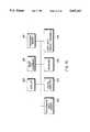
- a typical graphical representation of a tonescale transform LUT as derived aboveis shown in FIG. 8.
- tonescale buttons shown in the image processing window of FIG. 14allow the user to perform the following tonescaling operations on the transform LUT:
- FIGS. 12 and 13illustrate the effect of changing window width and window level on a transform LUT.
- FIG. 7is provided with vertical and horizontal scroll bars which allow changing of window width by moving a cursor up and down the vertical scroll bar and which allow changing window level by moving a cursor left and right on the horizontal scroll bar.
- movement of a mouse or trackball (308) in X (left-right) and Y (up-down) directionscan effect changes in window width and level simultaneously.
- QCW 202functions to effect real-time window/leveling of a displayed radiographic image. This function allows the user to make changes to the window and level parameters, and see immediate results on the currently displayed computed radiography image.
- the QCW 202used a method for window/leveling an image which provided poor (slow) feedback to the user; as a result, the user-desired values for window and level were often difficult to achieve.
- the technique of the inventionprovides a continuous visual response as the user manipulates the input device (either a mouse or trackball).
- the QCW 202also uses a procedure to avoid the alteration of display colors already in use by the application.
- Real-time window/leveling of imagesrequires the following four LUTs which are cascaded in software in addition to a color LUT which resides in hardware.
- the preference lutis used to give the image an overall appearance, i.e. a "regular" look (the transform lut or white bones), black bone, high contrast.
- the gamma lutis used to correct for the non-linear response of the QCW 202 video display screen.
- the window/level lutis used to select a region of interest within the displayed radiographic image, where level adjusts the brightness of the image, and window adjusts the contrast.
- the number of color cells used by the application programinforms the image processing software as to how many of the entries in the color LUT are already in use. In the QCW application, this value is usually less than ten.
- Another lookup table, one stored in the display hardwareis also required for real-time window window/leveling: the color lut. Like the crt lut, it is 8 bits wide and 256 bytes long. It is used by the display hardware to map pixel input values to video display tube output pixels.
- An exemplary deviceis the Bt 459 RAM DACTM supplied by Brooktree Corp., San Diego, Calif. This device combines a high speed RAM with DACs (digital-to-analog converters).
- the number of color cells used parameterinforms the image processing software about the elements (and their locations) in the hardware color map. In order to avoid changing the color and/or intensity of the QCW window borders, scroll bars, etc. (see e.g., FIG. 7), these color map locations should not be altered. The window/leveling of the displayed image, along with the scroll bars, etc., can be distracting to the user.
- real-time window/leveling of a displayed radiographic imageis as follows:
- the user of QCW 202requested that a specific image from radiographic image memory 302 be displayed on display 300, for the purpose of verifying image quality; poor images could be windowed and leveled.
- the user of QCW 202then holds down the left mouse button of user input device 308; while holding the mouse button and simultaneously moving the mouse, the user would see the image on the display 300, with the last sampled window/level values applied to it.
- the difference with this schemeis that the time between the user's mouse movement, and processing/redisplay of the image is very short. The time is so short as to appear tightly coupled to the user's mouse movements. This results in faster and easier window/leveling of images in the QCW system.
- the image processing software in digital computer 304recalculates the window/level lut, then cascades the gamma, tonescale, and window/level LUTs into the crt LUT.
- the crt LUTis loaded into the color lut, which is store din hardware 312. In this way, the pixels displayed for the current image are manipulated via the display hardware 312, as proposed to doing the same operation in hardware.
Landscapes
- Physics & Mathematics (AREA)
- General Physics & Mathematics (AREA)
- Engineering & Computer Science (AREA)
- Theoretical Computer Science (AREA)
- Image Processing (AREA)
- Apparatus For Radiation Diagnosis (AREA)
- Controls And Circuits For Display Device (AREA)
- Image Analysis (AREA)
Abstract
Description
______________________________________ the gamma lut (12 bit in, 8 bit out) the window/level lut (12 bit in, 12 bit out) the preference lut (12 bit in, 12 bit out) the crt lut (12 bits in/8 bits out) ______________________________________
______________________________________ the gamma lut (12 bit in, 8 bit out) the window/level lut (12 bit in, 12 bit out) the preference lut (12 bit in, 12 bit out) the crt lut (12 bits in/8 bits out) the color lut (8 bits in/8 bits out) ______________________________________
Claims (5)
Priority Applications (4)
| Application Number | Priority Date | Filing Date | Title |
|---|---|---|---|
| US08/086,968US5447153A (en) | 1993-07-02 | 1993-07-02 | Real-time window/leveling on a radiographic workstation |
| JP14766194AJP3651930B2 (en) | 1993-07-02 | 1994-06-29 | Real-time window / leveling system for radiation inspection workstation |
| DE69419984TDE69419984T2 (en) | 1993-07-02 | 1994-06-29 | Real-time adjustment of window width and level in a radiographic workstation |
| EP94110053AEP0632406B1 (en) | 1993-07-02 | 1994-06-29 | Real-time window/leveling on a radiographic workstation |
Applications Claiming Priority (1)
| Application Number | Priority Date | Filing Date | Title |
|---|---|---|---|
| US08/086,968US5447153A (en) | 1993-07-02 | 1993-07-02 | Real-time window/leveling on a radiographic workstation |
Publications (1)
| Publication Number | Publication Date |
|---|---|
| US5447153Atrue US5447153A (en) | 1995-09-05 |
Family
ID=22202037
Family Applications (1)
| Application Number | Title | Priority Date | Filing Date |
|---|---|---|---|
| US08/086,968Expired - LifetimeUS5447153A (en) | 1993-07-02 | 1993-07-02 | Real-time window/leveling on a radiographic workstation |
Country Status (4)
| Country | Link |
|---|---|
| US (1) | US5447153A (en) |
| EP (1) | EP0632406B1 (en) |
| JP (1) | JP3651930B2 (en) |
| DE (1) | DE69419984T2 (en) |
Cited By (18)
| Publication number | Priority date | Publication date | Assignee | Title |
|---|---|---|---|---|
| US5797397A (en)* | 1996-11-25 | 1998-08-25 | Hewlett-Packard Company | Ultrasound imaging system and method using intensity highlighting to facilitate tissue differentiation |
| EP0992156A1 (en)* | 1997-06-27 | 2000-04-12 | Delft Instruments Intellectual Property B.V. | Method and device for reproducing images |
| US6127669A (en)* | 1997-01-29 | 2000-10-03 | University Of Maryland | Computer-aided determination of window and level settings for filmless radiology |
| US6230043B1 (en)* | 1998-09-30 | 2001-05-08 | General Electric Company | Method and apparatus for capturing and automatically transferring an x-ray image to a remote location |
| US6249596B1 (en)* | 1993-11-23 | 2001-06-19 | Agfa-Gevaert | Method of locating saturated pixels in the display of a radiographic image |
| US6418334B1 (en)* | 1999-10-19 | 2002-07-09 | General Electric Company | Method and apparatus for logging and dynamically configuring performance analysis of a medical diagnostic imaging system |
| US20020141623A1 (en)* | 2001-03-29 | 2002-10-03 | Aleksandar Zavaljevski | Method for multi-path rendering of medical images |
| US20020168109A1 (en)* | 2001-04-03 | 2002-11-14 | Canon Kabushiki Kaisha | Image processing apparatus, image processing method, storage medium, and program |
| US6483933B1 (en)* | 1998-12-30 | 2002-11-19 | Ge Medical Systems Global Technology Company, Llc | Digital-to-film radiographic image conversion including a network |
| US20040196958A1 (en)* | 2002-11-29 | 2004-10-07 | Werner Beck | Operating device for a diagnostic imaging unit |
| US20060117270A1 (en)* | 2004-11-29 | 2006-06-01 | Canon, U.S.A., Inc. | Display parameter adjustment |
| US20070036419A1 (en)* | 2005-08-09 | 2007-02-15 | General Electric Company | System and method for interactive definition of image field of view in digital radiography |
| US20070177779A1 (en)* | 2006-01-31 | 2007-08-02 | Dennison Donald K | Window leveling system and method |
| US20080107313A1 (en)* | 2006-11-07 | 2008-05-08 | O'dea Paul Joseph | Methods and Apparatus to Facilitate Picture Archiving |
| US20090067700A1 (en)* | 2007-09-10 | 2009-03-12 | Riverain Medical Group, Llc | Presentation of computer-aided detection/diagnosis (CAD) results |
| KR20140141746A (en)* | 2013-05-30 | 2014-12-11 | 삼성전자주식회사 | Radiation imaging apparatus and method for representation of radioacitve image of the same |
| US20150254401A1 (en)* | 2014-03-06 | 2015-09-10 | Ricoh Co., Ltd. | Film to dicom conversion |
| US9235905B2 (en) | 2013-03-13 | 2016-01-12 | Ologn Technologies Ag | Efficient screen image transfer |
Families Citing this family (6)
| Publication number | Priority date | Publication date | Assignee | Title |
|---|---|---|---|---|
| JP3290027B2 (en)* | 1994-04-06 | 2002-06-10 | 株式会社モリタ製作所 | X-ray image display method and apparatus |
| JP2964321B2 (en) | 1997-09-01 | 1999-10-18 | ジーイー横河メディカルシステム株式会社 | Image display method, image display device, and image diagnostic device |
| US20030069480A1 (en)* | 2001-04-28 | 2003-04-10 | Baxter International Inc. | A system and method for networking blood collection instruments within a blood collection facility |
| DE10255956B4 (en)* | 2002-11-29 | 2006-09-14 | Siemens Ag | Operating device for a diagnostic imaging device |
| GB201002632D0 (en)* | 2010-02-16 | 2010-03-31 | Im Sense Ltd | Method and system for generating enhanced images |
| BE1021549B1 (en)* | 2011-07-06 | 2015-12-11 | Agfa Healthcare | Radiography system and radiography method for reading X-ray information stored in storage phosphor plates |
Citations (20)
| Publication number | Priority date | Publication date | Assignee | Title |
|---|---|---|---|---|
| US4079417A (en)* | 1976-07-06 | 1978-03-14 | General Electric Company | Digital video window control |
| US4125858A (en)* | 1976-03-27 | 1978-11-14 | Emi Limited | Video display arrangements |
| US4438495A (en)* | 1981-11-13 | 1984-03-20 | General Electric Company | Tomography window-level gamma functions |
| US4595949A (en)* | 1983-07-26 | 1986-06-17 | Paul Fenster | Systems and methods for translating radiation intensity into pixel values |
| US4642621A (en)* | 1983-11-29 | 1987-02-10 | Yokogawa Medical Systems, Limited | Image display system for computerized tomographs |
| US4688175A (en)* | 1983-09-30 | 1987-08-18 | Kabushiki Kaisha Toshiba | Image processor with automatic setting of window width and level for individual blocks of the image |
| US4803639A (en)* | 1986-02-25 | 1989-02-07 | General Electric Company | X-ray inspection system |
| GB2210533A (en)* | 1987-10-02 | 1989-06-07 | Gen Electric | Highlighting subtle contrast in graphical images |
| US4847604A (en)* | 1987-08-27 | 1989-07-11 | Doyle Michael D | Method and apparatus for identifying features of an image on a video display |
| US4852002A (en)* | 1985-05-10 | 1989-07-25 | Thomson-Cgr | Method for adjusting the gray scale in the reproduction of digitized images and a system for carrying out said method |
| EP0434208A1 (en)* | 1989-11-17 | 1991-06-26 | Picker International, Inc. | Imaging systems and methods |
| US5042077A (en)* | 1987-10-02 | 1991-08-20 | General Electric Company | Method of highlighting subtle contrast in graphical images |
| US5046027A (en)* | 1988-11-08 | 1991-09-03 | Massachusetts General Hospital | Apparatus and method for processing and displaying images in a digital procesor based system |
| US5058176A (en)* | 1986-07-02 | 1991-10-15 | Yokogawa Medical Systems, Limited | Image diagnosis apparatus |
| US5090042A (en)* | 1990-12-24 | 1992-02-18 | Bejjani Fadi J | Videofluoroscopy system for in vivo motion analysis |
| US5164993A (en)* | 1991-11-25 | 1992-11-17 | Eastman Kodak Company | Method and apparatus for automatic tonescale generation in digital radiographic images |
| US5179651A (en)* | 1988-11-08 | 1993-01-12 | Massachusetts General Hospital | Apparatus for retrieval and processing of selected archived images for display at workstation terminals |
| US5182728A (en)* | 1991-06-28 | 1993-01-26 | Acoustic Imaging Technologies Corporation | Ultrasound imaging system and method |
| US5268967A (en)* | 1992-06-29 | 1993-12-07 | Eastman Kodak Company | Method for automatic foreground and background detection in digital radiographic images |
| US5270530A (en)* | 1992-11-24 | 1993-12-14 | Eastman Kodak Company | Digital radiographic image quality control workstation operable in manual or pass-through modes |
Family Cites Families (2)
| Publication number | Priority date | Publication date | Assignee | Title |
|---|---|---|---|---|
| US4394688A (en)* | 1981-08-25 | 1983-07-19 | Hamamatsu Systems, Inc. | Video system having an adjustable digital gamma correction for contrast enhancement |
| US5042078A (en)* | 1987-06-19 | 1991-08-20 | Fuji Photo Film Co., Ltd. | Method of effecting gradation and color correction of a composite image |
- 1993
- 1993-07-02USUS08/086,968patent/US5447153A/ennot_activeExpired - Lifetime
- 1994
- 1994-06-29EPEP94110053Apatent/EP0632406B1/ennot_activeExpired - Lifetime
- 1994-06-29DEDE69419984Tpatent/DE69419984T2/ennot_activeExpired - Fee Related
- 1994-06-29JPJP14766194Apatent/JP3651930B2/ennot_activeExpired - Fee Related
Patent Citations (20)
| Publication number | Priority date | Publication date | Assignee | Title |
|---|---|---|---|---|
| US4125858A (en)* | 1976-03-27 | 1978-11-14 | Emi Limited | Video display arrangements |
| US4079417A (en)* | 1976-07-06 | 1978-03-14 | General Electric Company | Digital video window control |
| US4438495A (en)* | 1981-11-13 | 1984-03-20 | General Electric Company | Tomography window-level gamma functions |
| US4595949A (en)* | 1983-07-26 | 1986-06-17 | Paul Fenster | Systems and methods for translating radiation intensity into pixel values |
| US4688175A (en)* | 1983-09-30 | 1987-08-18 | Kabushiki Kaisha Toshiba | Image processor with automatic setting of window width and level for individual blocks of the image |
| US4642621A (en)* | 1983-11-29 | 1987-02-10 | Yokogawa Medical Systems, Limited | Image display system for computerized tomographs |
| US4852002A (en)* | 1985-05-10 | 1989-07-25 | Thomson-Cgr | Method for adjusting the gray scale in the reproduction of digitized images and a system for carrying out said method |
| US4803639A (en)* | 1986-02-25 | 1989-02-07 | General Electric Company | X-ray inspection system |
| US5058176A (en)* | 1986-07-02 | 1991-10-15 | Yokogawa Medical Systems, Limited | Image diagnosis apparatus |
| US4847604A (en)* | 1987-08-27 | 1989-07-11 | Doyle Michael D | Method and apparatus for identifying features of an image on a video display |
| GB2210533A (en)* | 1987-10-02 | 1989-06-07 | Gen Electric | Highlighting subtle contrast in graphical images |
| US5042077A (en)* | 1987-10-02 | 1991-08-20 | General Electric Company | Method of highlighting subtle contrast in graphical images |
| US5179651A (en)* | 1988-11-08 | 1993-01-12 | Massachusetts General Hospital | Apparatus for retrieval and processing of selected archived images for display at workstation terminals |
| US5046027A (en)* | 1988-11-08 | 1991-09-03 | Massachusetts General Hospital | Apparatus and method for processing and displaying images in a digital procesor based system |
| EP0434208A1 (en)* | 1989-11-17 | 1991-06-26 | Picker International, Inc. | Imaging systems and methods |
| US5090042A (en)* | 1990-12-24 | 1992-02-18 | Bejjani Fadi J | Videofluoroscopy system for in vivo motion analysis |
| US5182728A (en)* | 1991-06-28 | 1993-01-26 | Acoustic Imaging Technologies Corporation | Ultrasound imaging system and method |
| US5164993A (en)* | 1991-11-25 | 1992-11-17 | Eastman Kodak Company | Method and apparatus for automatic tonescale generation in digital radiographic images |
| US5268967A (en)* | 1992-06-29 | 1993-12-07 | Eastman Kodak Company | Method for automatic foreground and background detection in digital radiographic images |
| US5270530A (en)* | 1992-11-24 | 1993-12-14 | Eastman Kodak Company | Digital radiographic image quality control workstation operable in manual or pass-through modes |
Cited By (28)
| Publication number | Priority date | Publication date | Assignee | Title |
|---|---|---|---|---|
| US6249596B1 (en)* | 1993-11-23 | 2001-06-19 | Agfa-Gevaert | Method of locating saturated pixels in the display of a radiographic image |
| US5797397A (en)* | 1996-11-25 | 1998-08-25 | Hewlett-Packard Company | Ultrasound imaging system and method using intensity highlighting to facilitate tissue differentiation |
| US6127669A (en)* | 1997-01-29 | 2000-10-03 | University Of Maryland | Computer-aided determination of window and level settings for filmless radiology |
| EP0992156A1 (en)* | 1997-06-27 | 2000-04-12 | Delft Instruments Intellectual Property B.V. | Method and device for reproducing images |
| US6230043B1 (en)* | 1998-09-30 | 2001-05-08 | General Electric Company | Method and apparatus for capturing and automatically transferring an x-ray image to a remote location |
| US6483933B1 (en)* | 1998-12-30 | 2002-11-19 | Ge Medical Systems Global Technology Company, Llc | Digital-to-film radiographic image conversion including a network |
| US6418334B1 (en)* | 1999-10-19 | 2002-07-09 | General Electric Company | Method and apparatus for logging and dynamically configuring performance analysis of a medical diagnostic imaging system |
| US20020141623A1 (en)* | 2001-03-29 | 2002-10-03 | Aleksandar Zavaljevski | Method for multi-path rendering of medical images |
| US6807293B2 (en)* | 2001-03-29 | 2004-10-19 | Ge Medical Systems Global Technology Company, Llp | Method for multi-path rendering of medical images |
| US20020168109A1 (en)* | 2001-04-03 | 2002-11-14 | Canon Kabushiki Kaisha | Image processing apparatus, image processing method, storage medium, and program |
| US7024036B2 (en)* | 2001-04-03 | 2006-04-04 | Canon Kabushiki Kaisha | Image processing apparatus, image processing method, storage medium, and program |
| US20040196958A1 (en)* | 2002-11-29 | 2004-10-07 | Werner Beck | Operating device for a diagnostic imaging unit |
| US20060117270A1 (en)* | 2004-11-29 | 2006-06-01 | Canon, U.S.A., Inc. | Display parameter adjustment |
| US7516417B2 (en)* | 2004-11-29 | 2009-04-07 | Canon U.S.A. | Display parameter adjustment |
| US20070036419A1 (en)* | 2005-08-09 | 2007-02-15 | General Electric Company | System and method for interactive definition of image field of view in digital radiography |
| US20070177779A1 (en)* | 2006-01-31 | 2007-08-02 | Dennison Donald K | Window leveling system and method |
| US7869642B2 (en) | 2006-01-31 | 2011-01-11 | Agfa Inc. | Window leveling system and method |
| US20080107313A1 (en)* | 2006-11-07 | 2008-05-08 | O'dea Paul Joseph | Methods and Apparatus to Facilitate Picture Archiving |
| US20090067700A1 (en)* | 2007-09-10 | 2009-03-12 | Riverain Medical Group, Llc | Presentation of computer-aided detection/diagnosis (CAD) results |
| WO2009035977A1 (en)* | 2007-09-10 | 2009-03-19 | Riverain Medical Group, Llc | Presentation of computer-aided detection/diagnosis (cad) results |
| US9235905B2 (en) | 2013-03-13 | 2016-01-12 | Ologn Technologies Ag | Efficient screen image transfer |
| US9848207B2 (en) | 2013-03-13 | 2017-12-19 | Ologn Technologies Ag | Efficient screen image transfer |
| KR20140141746A (en)* | 2013-05-30 | 2014-12-11 | 삼성전자주식회사 | Radiation imaging apparatus and method for representation of radioacitve image of the same |
| US20170294007A1 (en)* | 2013-05-30 | 2017-10-12 | Samsung Electronics Co., Ltd. | Radiographic imaging apparatus and control method thereof |
| US10719925B2 (en)* | 2013-05-30 | 2020-07-21 | Samsung Electronics Co., Ltd. | Radiographic imaging apparatus and control method thereof |
| US20150254401A1 (en)* | 2014-03-06 | 2015-09-10 | Ricoh Co., Ltd. | Film to dicom conversion |
| US9965588B2 (en)* | 2014-03-06 | 2018-05-08 | Ricoh Co., Ltd. | Film to DICOM conversion |
| US10354754B2 (en) | 2014-03-06 | 2019-07-16 | Ricoh Co., Ltd. | Film to DICOM conversion |
Also Published As
| Publication number | Publication date |
|---|---|
| EP0632406B1 (en) | 1999-08-11 |
| DE69419984D1 (en) | 1999-09-16 |
| JP3651930B2 (en) | 2005-05-25 |
| DE69419984T2 (en) | 2000-02-10 |
| EP0632406A1 (en) | 1995-01-04 |
| JPH0757083A (en) | 1995-03-03 |
Similar Documents
| Publication | Publication Date | Title |
|---|---|---|
| US5447153A (en) | Real-time window/leveling on a radiographic workstation | |
| US5671070A (en) | Tonal consistency in a radiographic image network | |
| US5270530A (en) | Digital radiographic image quality control workstation operable in manual or pass-through modes | |
| EP0599097B1 (en) | Automatic routing to selected destinations of digital X-ray images | |
| US5592374A (en) | Patient identification and x-ray exam data collection bar code system | |
| US20030002629A1 (en) | Examination system, image processing apparatus and method, medium, and x-ray photographic system | |
| Carter et al. | Digital Radiography and PACS E-Book: Digital Radiography and PACS E-Book | |
| JPH085797A (en) | System to supply processed radiograph picture to remote device | |
| EP0913792B1 (en) | Pathology dependent viewing of processed dental radiographic film having authentication data | |
| US20040071263A1 (en) | Apparatus, system and program for controlling operation of photographing medical image | |
| EP0599098B1 (en) | Multiple versions of storage phosphor image | |
| US20050008262A1 (en) | Medical image system, and medical image processing method | |
| JP3530210B2 (en) | Image output control device | |
| US5686953A (en) | Imaging system and method using linear perceived optical density interface | |
| JP3051902B2 (en) | Radiation image information reading and displaying device | |
| JP2646203B2 (en) | X-ray image processing device | |
| JPH1153510A (en) | Medical image display device | |
| JPH05298418A (en) | Radiation image display device | |
| JPH07115536A (en) | Image output controller | |
| JPH08294480A (en) | X-ray radiographic image processor | |
| JPH0924040A (en) | X-ray image processing device | |
| JPH08272951A (en) | X-ray image processor | |
| JP2003058140A (en) | Image processor and method for image processing, program implementing image processing method, storage medium stored with program implementing image processing method, and image display device | |
| JPH0916762A (en) | Image processor | |
| EP0910041A1 (en) | Pathology dependent viewing of processed dental radiographic film |
Legal Events
| Date | Code | Title | Description |
|---|---|---|---|
| STPP | Information on status: patent application and granting procedure in general | Free format text:APPLICATION UNDERGOING PREEXAM PROCESSING | |
| AS | Assignment | Owner name:EASTMAN KODAK COMPANY, NEW YORK Free format text:ASSIGNMENT OF ASSIGNORS INTEREST;ASSIGNORS:WEIL, RICHARD;MODNEY, DAVID L.;DIANA, GARY M.;AND OTHERS;REEL/FRAME:006683/0855;SIGNING DATES FROM 19930813 TO 19930830 | |
| FEPP | Fee payment procedure | Free format text:PAYOR NUMBER ASSIGNED (ORIGINAL EVENT CODE: ASPN); ENTITY STATUS OF PATENT OWNER: LARGE ENTITY | |
| FEPP | Fee payment procedure | Free format text:PAYOR NUMBER ASSIGNED (ORIGINAL EVENT CODE: ASPN); ENTITY STATUS OF PATENT OWNER: LARGE ENTITY Free format text:PAYER NUMBER DE-ASSIGNED (ORIGINAL EVENT CODE: RMPN); ENTITY STATUS OF PATENT OWNER: LARGE ENTITY | |
| FPAY | Fee payment | Year of fee payment:4 | |
| FPAY | Fee payment | Year of fee payment:8 | |
| FPAY | Fee payment | Year of fee payment:12 | |
| AS | Assignment | Owner name:CREDIT SUISSE, CAYMAN ISLANDS BRANCH, AS ADMINISTR Free format text:FIRST LIEN OF INTELLECTUAL PROPERTY SECURITY AGREEMENT;ASSIGNOR:CARESTREAM HEALTH, INC.;REEL/FRAME:019649/0454 Effective date:20070430 Owner name:CREDIT SUISSE, CAYMAN ISLANDS BRANCH, AS ADMINISTR Free format text:SECOND LIEN INTELLECTUAL PROPERTY SECURITY AGREEME;ASSIGNOR:CARESTREAM HEALTH, INC.;REEL/FRAME:019773/0319 Effective date:20070430 | |
| AS | Assignment | Owner name:CARESTREAM HEALTH, INC., NEW YORK Free format text:ASSIGNMENT OF ASSIGNORS INTEREST;ASSIGNOR:EASTMAN KODAK COMPANY;REEL/FRAME:020741/0126 Effective date:20070501 Owner name:CARESTREAM HEALTH, INC., NEW YORK Free format text:ASSIGNMENT OF ASSIGNORS INTEREST;ASSIGNOR:EASTMAN KODAK COMPANY;REEL/FRAME:020756/0500 Effective date:20070501 Owner name:CARESTREAM HEALTH, INC.,NEW YORK Free format text:ASSIGNMENT OF ASSIGNORS INTEREST;ASSIGNOR:EASTMAN KODAK COMPANY;REEL/FRAME:020741/0126 Effective date:20070501 Owner name:CARESTREAM HEALTH, INC.,NEW YORK Free format text:ASSIGNMENT OF ASSIGNORS INTEREST;ASSIGNOR:EASTMAN KODAK COMPANY;REEL/FRAME:020756/0500 Effective date:20070501 | |
| AS | Assignment | Owner name:CARESTREAM HEALTH, INC., NEW YORK Free format text:RELEASE OF SECURITY INTEREST IN INTELLECTUAL PROPERTY (FIRST LIEN);ASSIGNOR:CREDIT SUISSE AG, CAYMAN ISLANDS BRANCH;REEL/FRAME:026069/0012 Effective date:20110225 | |
| AS | Assignment | Owner name:CREDIT SUISSE AG, CAYMAN ISLANDS BRANCH, NEW YORK Free format text:INTELLECTUAL PROPERTY SECURITY AGREEMENT;ASSIGNORS:CARESTREAM HEALTH, INC.;CARESTREAM DENTAL, LLC;QUANTUM MEDICAL IMAGING, L.L.C.;AND OTHERS;REEL/FRAME:026269/0411 Effective date:20110225 | |
| AS | Assignment | Owner name:CARESTREAM HEALTH, INC., NEW YORK Free format text:RELEASE OF SECURITY INTEREST IN INTELLECTUAL PROPERTY (SECOND LIEN);ASSIGNOR:CREDIT SUISSE AG, CAYMAN ISLANDS BRANCH;REEL/FRAME:027851/0812 Effective date:20110225 | |
| AS | Assignment | Owner name:CREDIT SUISSE AG, CAYMAN ISLANDS BRANCH, NEW YORK Free format text:AMENDED AND RESTATED INTELLECTUAL PROPERTY SECURITY AGREEMENT (FIRST LIEN);ASSIGNORS:CARESTREAM HEALTH, INC.;CARESTREAM DENTAL LLC;QUANTUM MEDICAL IMAGING, L.L.C.;AND OTHERS;REEL/FRAME:030711/0648 Effective date:20130607 | |
| AS | Assignment | Owner name:CREDIT SUISSE AG, CAYMAN ISLANDS BRANCH, NEW YORK Free format text:SECOND LIEN INTELLECTUAL PROPERTY SECURITY AGREEMENT;ASSIGNORS:CARESTREAM HEALTH, INC.;CARESTREAM DENTAL LLC;QUANTUM MEDICAL IMAGING, L.L.C.;AND OTHERS;REEL/FRAME:030724/0154 Effective date:20130607 | |
| AS | Assignment | Owner name:TROPHY DENTAL INC., GEORGIA Free format text:RELEASE BY SECURED PARTY;ASSIGNOR:CREDIT SUISSE AG, CAYMAN ISLANDS BRANCH;REEL/FRAME:061681/0380 Effective date:20220930 Owner name:QUANTUM MEDICAL HOLDINGS, LLC, NEW YORK Free format text:RELEASE BY SECURED PARTY;ASSIGNOR:CREDIT SUISSE AG, CAYMAN ISLANDS BRANCH;REEL/FRAME:061681/0380 Effective date:20220930 Owner name:QUANTUM MEDICAL IMAGING, L.L.C., NEW YORK Free format text:RELEASE BY SECURED PARTY;ASSIGNOR:CREDIT SUISSE AG, CAYMAN ISLANDS BRANCH;REEL/FRAME:061681/0380 Effective date:20220930 Owner name:CARESTREAM DENTAL, LLC, GEORGIA Free format text:RELEASE BY SECURED PARTY;ASSIGNOR:CREDIT SUISSE AG, CAYMAN ISLANDS BRANCH;REEL/FRAME:061681/0380 Effective date:20220930 Owner name:CARESTREAM HEALTH, INC., NEW YORK Free format text:RELEASE BY SECURED PARTY;ASSIGNOR:CREDIT SUISSE AG, CAYMAN ISLANDS BRANCH;REEL/FRAME:061681/0380 Effective date:20220930 Owner name:TROPHY DENTAL INC., NEW YORK Free format text:RELEASE OF SECURITY INTEREST IN INTELLECTUAL PROPERTY (FIRST LIEN);ASSIGNOR:CREDIT SUISSE AG, CAYMAN ISLANDS BRANCH;REEL/FRAME:061683/0441 Effective date:20220930 Owner name:QUANTUM MEDICAL IMAGING, L.L.C., NEW YORK Free format text:RELEASE OF SECURITY INTEREST IN INTELLECTUAL PROPERTY (FIRST LIEN);ASSIGNOR:CREDIT SUISSE AG, CAYMAN ISLANDS BRANCH;REEL/FRAME:061683/0441 Effective date:20220930 Owner name:CARESTREAM DENTAL LLC, GEORGIA Free format text:RELEASE OF SECURITY INTEREST IN INTELLECTUAL PROPERTY (FIRST LIEN);ASSIGNOR:CREDIT SUISSE AG, CAYMAN ISLANDS BRANCH;REEL/FRAME:061683/0441 Effective date:20220930 Owner name:CARESTREAM HEALTH, INC., NEW YORK Free format text:RELEASE OF SECURITY INTEREST IN INTELLECTUAL PROPERTY (FIRST LIEN);ASSIGNOR:CREDIT SUISSE AG, CAYMAN ISLANDS BRANCH;REEL/FRAME:061683/0441 Effective date:20220930 Owner name:TROPHY DENTAL INC., GEORGIA Free format text:RELEASE OF SECURITY INTEREST IN INTELLECTUAL PROPERTY (SECOND LIEN);ASSIGNOR:CREDIT SUISSE AG, CAYMAN ISLANDS BRANCH;REEL/FRAME:061683/0601 Effective date:20220930 Owner name:QUANTUM MEDICAL IMAGING, L.L.C., NEW YORK Free format text:RELEASE OF SECURITY INTEREST IN INTELLECTUAL PROPERTY (SECOND LIEN);ASSIGNOR:CREDIT SUISSE AG, CAYMAN ISLANDS BRANCH;REEL/FRAME:061683/0601 Effective date:20220930 Owner name:CARESTREAM DENTAL LLC, GEORGIA Free format text:RELEASE OF SECURITY INTEREST IN INTELLECTUAL PROPERTY (SECOND LIEN);ASSIGNOR:CREDIT SUISSE AG, CAYMAN ISLANDS BRANCH;REEL/FRAME:061683/0601 Effective date:20220930 Owner name:CARESTREAM HEALTH, INC., NEW YORK Free format text:RELEASE OF SECURITY INTEREST IN INTELLECTUAL PROPERTY (SECOND LIEN);ASSIGNOR:CREDIT SUISSE AG, CAYMAN ISLANDS BRANCH;REEL/FRAME:061683/0601 Effective date:20220930 |