US5446481A - Multidimensional hybrid mouse for computers - Google Patents
Multidimensional hybrid mouse for computersDownload PDFInfo
- Publication number
- US5446481A US5446481AUS07/772,395US77239591AUS5446481AUS 5446481 AUS5446481 AUS 5446481AUS 77239591 AUS77239591 AUS 77239591AUS 5446481 AUS5446481 AUS 5446481A
- Authority
- US
- United States
- Prior art keywords
- motion
- roller
- mouse
- roll
- pitch
- Prior art date
- Legal status (The legal status is an assumption and is not a legal conclusion. Google has not performed a legal analysis and makes no representation as to the accuracy of the status listed.)
- Expired - Lifetime
Links
Images


Classifications
- G—PHYSICS
- G06—COMPUTING OR CALCULATING; COUNTING
- G06F—ELECTRIC DIGITAL DATA PROCESSING
- G06F3/00—Input arrangements for transferring data to be processed into a form capable of being handled by the computer; Output arrangements for transferring data from processing unit to output unit, e.g. interface arrangements
- G06F3/01—Input arrangements or combined input and output arrangements for interaction between user and computer
- G06F3/03—Arrangements for converting the position or the displacement of a member into a coded form
- G06F3/033—Pointing devices displaced or positioned by the user, e.g. mice, trackballs, pens or joysticks; Accessories therefor
- G06F3/0354—Pointing devices displaced or positioned by the user, e.g. mice, trackballs, pens or joysticks; Accessories therefor with detection of 2D relative movements between the device, or an operating part thereof, and a plane or surface, e.g. 2D mice, trackballs, pens or pucks
- G06F3/03543—Mice or pucks
- H—ELECTRICITY
- H01—ELECTRIC ELEMENTS
- H01H—ELECTRIC SWITCHES; RELAYS; SELECTORS; EMERGENCY PROTECTIVE DEVICES
- H01H19/00—Switches operated by an operating part which is rotatable about a longitudinal axis thereof and which is acted upon directly by a solid body external to the switch, e.g. by a hand
- H01H19/02—Details
- H01H19/10—Movable parts; Contacts mounted thereon
- H01H19/14—Operating parts, e.g. turn knob
- H01H2019/146—Roller type actuators
- H—ELECTRICITY
- H01—ELECTRIC ELEMENTS
- H01H—ELECTRIC SWITCHES; RELAYS; SELECTORS; EMERGENCY PROTECTIVE DEVICES
- H01H25/00—Switches with compound movement of handle or other operating part
- H01H25/008—Operating part movable both angularly and rectilinearly, the rectilinear movement being perpendicular to the axis of angular movement
- Y—GENERAL TAGGING OF NEW TECHNOLOGICAL DEVELOPMENTS; GENERAL TAGGING OF CROSS-SECTIONAL TECHNOLOGIES SPANNING OVER SEVERAL SECTIONS OF THE IPC; TECHNICAL SUBJECTS COVERED BY FORMER USPC CROSS-REFERENCE ART COLLECTIONS [XRACs] AND DIGESTS
- Y10—TECHNICAL SUBJECTS COVERED BY FORMER USPC
- Y10T—TECHNICAL SUBJECTS COVERED BY FORMER US CLASSIFICATION
- Y10T74/00—Machine element or mechanism
- Y10T74/20—Control lever and linkage systems
- Y10T74/20012—Multiple controlled elements
- Y10T74/20201—Control moves in two planes
Definitions
- the inventionrelates to pointing devices for computers such as mice and trackballs.
- a mouseis a control device, used with a computer monitor, in which a transducer converts translational motion of a movable, hand-held device into a position signal, most frequently used for controlling a cursor. Movement of the device is converted to movement of the cursor. Motion is sensed in x and y directions, and sometimes rotation in the x-y plane known as yaw motion is also sensed, as the housing moves over a surface known as a pad. Analogous motion of the cursor in x and y directions takes place as the mouse delivers its position signals to an associated computer. Rotational motion is useful in applications software, such as drawing or computer aided design (CAD) programs.
- CADcomputer aided design
- a trackballis another cursor control device.
- a trackballconverts rotational motion of a ball into x,y quadrature signals, compatible with the x,y signals produced by a mouse.
- the ballis suspended in a fixed position, as shown in U.S. Pat. No. 4,933,670.
- the latter patentrecognizes that more than three degrees of freedom or dimensions may be desirable in a trackball and incorporates control buttons, annular rings about the ball, and a partial keyboard for additional commands.
- mice and trackballsare hand held devices, it would seem difficult to generate information on moving in six coordinate directions without something like a keyboard where, with a fair amount of training, human fingers can manipulate keys to supply a variety of computer input.
- An object of the inventionwas to find a hand held cursor control device capable of handling multiple degrees of freedom, yet which could be intuitively manipulated by a user without much training.
- the above objecthas been met by combining a dual detector mouse with a roller which adds at least one additional degree of freedom and, in alternative embodiments, adds two or more additional degrees of freedom.
- the rolleris mounted on a mouse housing so that a user can manipulate the roller while also able to actuate buttons on the mouse and control mouse movement.
- the rollerprovides a z degree of freedom, pointing to motion perpendicular to the x-y plane, i.e. usually perpendicular to the plane displayed on the monitor. For example, in a spreadsheet, this would be useful for showing spreadsheet layers above and below the one currently displayed in a three-dimensional spreadsheet. Another use could be in the situation where a three-dimensional object is shown in the manner such that the x-y plane is at an angle to the screen, thereby revealing a z-axis. The roller could be used to point along the z-axis, while the mouse could be used to point in the x-y plane.
- the rolleris supported within a mouse housing with the roller projecting through the housing. Turning of the roller by a human finger indicates the extent of z-axis position. Rotation of the roller is read by a shaft angle encoder which converts rotational motion of the roller into a number of pulse counts, indicating motion along the z-axis.
- the rolleris mounted in a suspension which allows tilting left and right. By tilting the roller either left or right, additional degrees of freedom may be indicated. For example, if the roller is tilted to the left, closing a connected switch, and then the roller is turned, the roller generated pulses could signify pitch. If the roller is tilted in the opposite direction and then turned, the pulse count could indicate roll.
- a trackballmay be combined with a mouse housing.
- a trackballhas two degrees of freedom in addition to those provided by the mouse.
- a further degree of freedomcould be provided by a roller near the trackball.
- a computer programcould display x, y and z coordinates, known as Cartesian coordinates, and at the same time also employ roll, pitch and yaw coordinates, in an angular coordinate system. Both coordinate systems could share the same origin and would be useful in computer programs employing graphics, where it is desirable to rotate objects using angular coordinates, as well as to draw and revise objects using normal Cartesian coordinates.
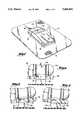
- FIG. 1is a perspective view of the hybrid mouse device of the present invention.
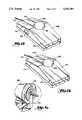
- FIG. 2is a rear view of the suspension mechanism for the roller employed in the apparatus of FIG. 1.
- FIGS. 3 and 4show tilting motion of the roller of FIG. 2.
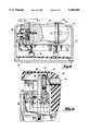
- FIG. 5is a perspective view of the roller and support, as well as shaft angle encoding apparatus, all employed in the hybrid mouse of FIG. 1.
- FIGS. 6, 7, 7A, 8, 9 and 10illustrate details of the shaft angle encoding apparatus illustrated in FIG. 5.
- FIG. 11is a perspective view of an alternative embodiment of the hybrid mouse of FIG. 1.
- FIG. 12is a second alternative embodiment of the hybrid mouse of FIG. 1.
- FIG. 13is a third alternative embodiment of the hybrid mouse of FIG. 1.
- a dual detector mouse 10is shown. Although this type of mouse is an optical mouse which employs a pad surface 12 with a pattern of grid lines 14, other mice, including non-optical mice, could be used as long as two detectors exist for this preferred embodiment. If two detectors do not exist, but only one detector exists as in most conventional mice, the present invention is still applicable, but with one less degree of freedom.
- Mouse 10is moved with reference to the pad and counts line crossings or otherwise determines motion relative to the pad or supporting surface.
- the mouseemploys optical detectors 16, indicated by dashed lines to measure line crossings.
- the mouseslides over the pad surface as it is moved by a human hand.
- Line crossing informationis converted to x and y motion signals.
- Using two optical detectorsit is possible to determine yaw motion when the x and y motion detectors report motion in opposite directions.
- the mousehas control buttons 18, 20 and 22 which serve signaling functions.
- a typical software programmight interpret a button signal to be equivalent to a carriage return or an escape character, although any assignment may be made.
- Mouse 10also includes a finger-operated roller 24.
- the size of the mouse deviceis comparable to a cigarette pack and so the control buttons 18, 20 and 22 would be within finger reach of the roller 24 without much movement of the position of the palm of the hand on the rear portion 26 of the mouse housing.
- the rollergenerates a z direction motion signal which would be perpendicular to the x-y plane, coinciding with pad surface 12. Recalling that the mouse provides x, y and yaw motion signals, the additional z direction signal gives the mouse a three-dimensional pointing capability, plus yaw motion.
- roller 24is shown to be supported by an arm 28 connected to upright beam 30 at pivot 32.
- Upright beam 30is U-shaped, allowing arm 28 to pass through the central portion of the U.
- Arm 28supports upright shrouds 34 and 36 which enclose support bearings for the axis of roller 24 so that the roller can turn when rotated by a finger.
- FIGS. 3 and 4show rocking motion of arm 28 about pivot 32. The amount of rocking is limited by a stop member 38 mounted within the open portion of the U-shaped upright beam 30.
- Support arm 28carries a pair of flexible fingers 40 and 42, shown in FIG. 5. One end of the fingers is mounted to arm 28, while a distal end, cantilevered from arm 28, carries contact rods 44 and 46 spaced slightly above normally open momentary microswitches 48 and 50, respectively.
- the contact rodsreside slightly above the movable, disk-like microswitch actuators and are not depressing the microswitches when roller 24 is in a level position, which is its normal state. However, if the roller is tilted to either side, as shown in FIG. 3 or FIG. 4, one of the flexible fingers 40 or 42 bends slightly as pressure is exerted upon it bringing the connected contact rod to bear against a respective microswitch, thereby closing the switch.
- Closing of a microswitchis indicative of signaling motion associated with another degree of freedom.
- the two directions which have been assigned to tilting left and right, as shown in FIGS. 3 and 4,is pitch and roll.
- the extent of motion associated with the new degree of freedomdepends upon the turning of roller 24 when the roller is in the selected tilted position. In other words, signaling pitch or roll requires both tilting and turning of the roller.
- Upright beam 30, as well as microswitches 48 and 50are mounted on the floor of the mouse housing or on a circuit board 52, shown in FIG. 8.
- shaft angle encoder 54is carried by arm 28 and serves to convert rotation of roller 24 into an electrical signal which is indicative of the extent of z axis motion or motion associated with the degrees of freedom defined by the two tilted positions of the roller 24.
- the shaft angle encoderincludes a non-rotating semicircular mask 56 with apertures defined therein, as well as a first optical transmitter 60 and a detector 58. A second optical transmitter and detector are mounted on a radially opposite side of the mask.
- a wheel 62Immediately behind mask 56 is a wheel 62, shown in FIG. 6.
- This wheelcarries a number of radially equally spaced slits 64 so that wheel 62 can act as a light chopper. If one slit exists within each two degree circumferential angle the wheel will have forty five slits and a resolution of eight degrees, assuming no frictional slippage of the roller. An optical pulse in each four degree slit can be resolved into 4 counts, thereby creating a signal resolution of two degrees.
- the axis of roller 24is locked to the axis of wheel 62 by means of gears as shown in FIG. 7.
- Arm 28carries a shaft 66 which mounts a first gear 68.
- This first gearhas teeth which mesh with a second gear 70 mounted at the end of the axial shaft of roller 24.
- a friction disk 72adhered to an end of roller 24, made of rayon fibers or the like, rubs against an upright roller support 74 attached to arm 28 to provide rotational resistance and prevent free-wheeling in the gears 68 and 70.
- mouse housing 76is seen to allow the top portion of roller 24 to project outwardly through the housing with slight clearance allowing rotation.
- the roller operational mechanismsare supported near board 52 which resides above the floor 78 of the mouse housing.
- the shaft angle encoder 54is covered by the shroud 34 which also projects through the top of the housing 76.
- Shroud 36is on the opposite side of roller 24.
- gear 70is seen to be supported on roller shaft 82 extending into the body of roller 24.
- Second arm 74supports the roller shaft 82.
- Optical transmitter 60may be seen directing a beam of light 84 through chopper wheel 62 and mask 56 to impinge upon detector 58.
- First transmitter 60directs light beam 84 to detector 58.
- Second beam 90is the counterpart of beam 84.
- the two signals from the detectorsare processed with a quadrature method to determine the proper pulse count.
- Quadrature pulse countersare well known.
- An arbitrary number of chopped light pulsesmay be assigned to an angle, although a one to one relationship may be preserved. In the latter case, forty-five pulses would represent ninety degrees of rotation, assuming one slit every two degrees.
- an arbitrary number of pulsesmay be assigned to a unit of distance. For example, forty-five pulses might be equivalent of one centimeter of motion of the mouse if the mouse were moving in the z direction.
- the roller 24is seen to be carried by a saddle 92 which is supported for tilting inside of the mouse housing 76. Once again, the tilting will serve to actuate a different degree of freedom than a roller turning by itself in the same way as the embodiment described with respect to FIG. 5.
- Saddle 92is received in an indentation 94 of housing 76.
- This embodimentis quite similar to the embodiment of FIG. 1 except that there is greater dust and moisture protection on the top surface of the housing.
- a conventional trackball 96is mounted at the top of the housing among control buttons 102, 104 and 106.
- a roller 98for signaling z-axis motion, is mounted at the side of housing 108.
- Trackball 96being a conventional two-dimensional cursor control device, will supply information relative to two additional degrees of freedom beyond that supplied by roller 98.
- An early version of a trackballis disclosed in U.S. Pat. No. 3,541,521 to R. A. Koster.
- Trackball 96is positioned in an opening which partially cuts away a portion of control buttons 102, 104 and 106. The purpose is to allow a user to manipulate the trackball as well as the control buttons.
- the position of roller 98is such that a thumb of a user on the housing 108 can operate the roller.
- a hybrid mouseis shown similar to that of FIG. 12, except that no roller is present.
- This embodimentemploys a dual detector mouse with optical sensors 110 and 112 together with control buttons 102, 104 and 106.
- Trackball 96is positioned in the same manner as in the previous embodiment. Output signals are the same, except there is no z-axis signal.
- the signals presentwould be the x,y and yaw signals produced in a conventional manner by the mouse 114 together with the pitch and roll signals produced by the trackball 96.
- the trackballis supported completely within the mouse housing and does not contact the surface which the mouse contacts. It is possible to mount more than one trackball in the mouse housing if the size of the housing is expanded. Each additional trackball would add two additional degrees of freedom.
- a "hybrid" mousedescribes either a dual detector mouse or a conventional single detector mouse combined with a z-axis roller or a trackball or both the roller and the trackball.
Landscapes
- Engineering & Computer Science (AREA)
- General Engineering & Computer Science (AREA)
- Theoretical Computer Science (AREA)
- Human Computer Interaction (AREA)
- Physics & Mathematics (AREA)
- General Physics & Mathematics (AREA)
- Position Input By Displaying (AREA)
Abstract
Description
1. Technical Field
The invention relates to pointing devices for computers such as mice and trackballs.
2. Background Art
A mouse is a control device, used with a computer monitor, in which a transducer converts translational motion of a movable, hand-held device into a position signal, most frequently used for controlling a cursor. Movement of the device is converted to movement of the cursor. Motion is sensed in x and y directions, and sometimes rotation in the x-y plane known as yaw motion is also sensed, as the housing moves over a surface known as a pad. Analogous motion of the cursor in x and y directions takes place as the mouse delivers its position signals to an associated computer. Rotational motion is useful in applications software, such as drawing or computer aided design (CAD) programs. An example of a mouse with optical sensors for detecting motion is U.S. Pat. No. 4,920,260, by K. Victor and C. Goy, assigned to the assignee of the present invention. In this patent the mouse moves over a pad having a repetitive pattern of optical markings which are illuminated by a beam of light. Line crossings are counted as a measure of motion of the device. U.S. Pat. No. 4,364,035 to S. Kirsch shows a similar device, with a different detection scheme. One of the features of the Kirsch mouse, described with reference to FIG. 6 of the '035 patent, is that it can detect rotation, as well as translation. See U.S. Pat. No. 4,797,544 to J. Montgomery which describes circuitry for tracking two optical detectors reporting two position locations X1, Y1 and X2, Y2 in order to compute rotation. See also U.S. Pat. No. 4,984,287 to Massoudi, assigned to the assignee of the present invention. Although the two detectors described in the latter two patents exist in a scanner, they could also exist in a mouse, as in the '035 Kirsch patent, hereafter collectively referred to as a "dual detector mouse".
A trackball is another cursor control device. A trackball converts rotational motion of a ball into x,y quadrature signals, compatible with the x,y signals produced by a mouse. The ball is suspended in a fixed position, as shown in U.S. Pat. No. 4,933,670. The latter patent recognizes that more than three degrees of freedom or dimensions may be desirable in a trackball and incorporates control buttons, annular rings about the ball, and a partial keyboard for additional commands.
The need for more than three degrees of freedom arises in new software applications, particularly graphics. For example, besides the usual x and y translation of images, rotation of images with yaw, roll and pitch is useful for examining the shape of an object. Moreover, a z degree of freedom is useful for pointing out depth of an object or for moving in an orthogonal direction in a spreadsheet to access depthwise layers of a three dimensional data space. This leads to 6 dimensions or degrees of freedom, even though roll, pitch and yaw are not necessarily independent of x, y and z. Rather roll, pitch and yaw can be another way of expressing motion in the same space as x, y and z.
Because mice and trackballs are hand held devices, it would seem difficult to generate information on moving in six coordinate directions without something like a keyboard where, with a fair amount of training, human fingers can manipulate keys to supply a variety of computer input. An object of the invention was to find a hand held cursor control device capable of handling multiple degrees of freedom, yet which could be intuitively manipulated by a user without much training.
The above object has been met by combining a dual detector mouse with a roller which adds at least one additional degree of freedom and, in alternative embodiments, adds two or more additional degrees of freedom. The roller is mounted on a mouse housing so that a user can manipulate the roller while also able to actuate buttons on the mouse and control mouse movement.
The roller provides a z degree of freedom, pointing to motion perpendicular to the x-y plane, i.e. usually perpendicular to the plane displayed on the monitor. For example, in a spreadsheet, this would be useful for showing spreadsheet layers above and below the one currently displayed in a three-dimensional spreadsheet. Another use could be in the situation where a three-dimensional object is shown in the manner such that the x-y plane is at an angle to the screen, thereby revealing a z-axis. The roller could be used to point along the z-axis, while the mouse could be used to point in the x-y plane.
The roller is supported within a mouse housing with the roller projecting through the housing. Turning of the roller by a human finger indicates the extent of z-axis position. Rotation of the roller is read by a shaft angle encoder which converts rotational motion of the roller into a number of pulse counts, indicating motion along the z-axis. The roller is mounted in a suspension which allows tilting left and right. By tilting the roller either left or right, additional degrees of freedom may be indicated. For example, if the roller is tilted to the left, closing a connected switch, and then the roller is turned, the roller generated pulses could signify pitch. If the roller is tilted in the opposite direction and then turned, the pulse count could indicate roll.
In another embodiment, rather than tilting the roller left and right in order to indicate pitch and roll, a trackball may be combined with a mouse housing. A trackball has two degrees of freedom in addition to those provided by the mouse. A further degree of freedom could be provided by a roller near the trackball.
With six degrees of freedom, a computer program could display x, y and z coordinates, known as Cartesian coordinates, and at the same time also employ roll, pitch and yaw coordinates, in an angular coordinate system. Both coordinate systems could share the same origin and would be useful in computer programs employing graphics, where it is desirable to rotate objects using angular coordinates, as well as to draw and revise objects using normal Cartesian coordinates.
FIG. 1 is a perspective view of the hybrid mouse device of the present invention.
FIG. 2 is a rear view of the suspension mechanism for the roller employed in the apparatus of FIG. 1.
FIGS. 3 and 4 show tilting motion of the roller of FIG. 2.
FIG. 5 is a perspective view of the roller and support, as well as shaft angle encoding apparatus, all employed in the hybrid mouse of FIG. 1.
FIGS. 6, 7, 7A, 8, 9 and 10 illustrate details of the shaft angle encoding apparatus illustrated in FIG. 5.
FIG. 11 is a perspective view of an alternative embodiment of the hybrid mouse of FIG. 1.
FIG. 12 is a second alternative embodiment of the hybrid mouse of FIG. 1.
FIG. 13 is a third alternative embodiment of the hybrid mouse of FIG. 1.
With reference to FIG. 1, adual detector mouse 10 is shown. Although this type of mouse is an optical mouse which employs apad surface 12 with a pattern ofgrid lines 14, other mice, including non-optical mice, could be used as long as two detectors exist for this preferred embodiment. If two detectors do not exist, but only one detector exists as in most conventional mice, the present invention is still applicable, but with one less degree of freedom.
With reference to FIG. 2,roller 24 is shown to be supported by anarm 28 connected toupright beam 30 atpivot 32.Upright beam 30 is U-shaped, allowingarm 28 to pass through the central portion of theU. Arm 28 supports upright shrouds 34 and 36 which enclose support bearings for the axis ofroller 24 so that the roller can turn when rotated by a finger.
FIGS. 3 and 4 show rocking motion ofarm 28 aboutpivot 32. The amount of rocking is limited by astop member 38 mounted within the open portion of theU-shaped upright beam 30.
Returning to FIG. 5,shaft angle encoder 54 is carried byarm 28 and serves to convert rotation ofroller 24 into an electrical signal which is indicative of the extent of z axis motion or motion associated with the degrees of freedom defined by the two tilted positions of theroller 24. The shaft angle encoder includes a non-rotatingsemicircular mask 56 with apertures defined therein, as well as a firstoptical transmitter 60 and adetector 58. A second optical transmitter and detector are mounted on a radially opposite side of the mask.
Immediately behindmask 56 is awheel 62, shown in FIG. 6. This wheel carries a number of radially equally spacedslits 64 so thatwheel 62 can act as a light chopper. If one slit exists within each two degree circumferential angle the wheel will have forty five slits and a resolution of eight degrees, assuming no frictional slippage of the roller. An optical pulse in each four degree slit can be resolved into 4 counts, thereby creating a signal resolution of two degrees.
To assure tight mechanical coupling between the roller andwheel 62, the axis ofroller 24 is locked to the axis ofwheel 62 by means of gears as shown in FIG. 7.Arm 28 carries ashaft 66 which mounts afirst gear 68. This first gear has teeth which mesh with asecond gear 70 mounted at the end of the axial shaft ofroller 24. In FIG. 7a, at the opposite end ofroller 24, afriction disk 72, adhered to an end ofroller 24, made of rayon fibers or the like, rubs against anupright roller support 74 attached toarm 28 to provide rotational resistance and prevent free-wheeling in thegears
In FIG. 8,mouse housing 76 is seen to allow the top portion ofroller 24 to project outwardly through the housing with slight clearance allowing rotation. The roller operational mechanisms are supported nearboard 52 which resides above thefloor 78 of the mouse housing. Theshaft angle encoder 54 is covered by theshroud 34 which also projects through the top of thehousing 76.Shroud 36 is on the opposite side ofroller 24.
In FIG. 9,gear 70 is seen to be supported onroller shaft 82 extending into the body ofroller 24.Second arm 74 supports theroller shaft 82.Optical transmitter 60 may be seen directing a beam of light 84 throughchopper wheel 62 andmask 56 to impinge upondetector 58.
In FIG. 10, both transmitters may be seen.First transmitter 60 directslight beam 84 todetector 58. On a opposite side of chopper wheel 62 atransmitter 88 directs light todetector 86.Second beam 90 is the counterpart ofbeam 84. The two signals from the detectors are processed with a quadrature method to determine the proper pulse count. Quadrature pulse counters are well known. An arbitrary number of chopped light pulses may be assigned to an angle, although a one to one relationship may be preserved. In the latter case, forty-five pulses would represent ninety degrees of rotation, assuming one slit every two degrees. For z direction motion, an arbitrary number of pulses may be assigned to a unit of distance. For example, forty-five pulses might be equivalent of one centimeter of motion of the mouse if the mouse were moving in the z direction.
In FIG. 11, theroller 24 is seen to be carried by asaddle 92 which is supported for tilting inside of themouse housing 76. Once again, the tilting will serve to actuate a different degree of freedom than a roller turning by itself in the same way as the embodiment described with respect to FIG. 5.Saddle 92 is received in anindentation 94 ofhousing 76. This embodiment is quite similar to the embodiment of FIG. 1 except that there is greater dust and moisture protection on the top surface of the housing.
In FIG. 12, aconventional trackball 96 is mounted at the top of the housing amongcontrol buttons roller 98, for signaling z-axis motion, is mounted at the side ofhousing 108. In the preferred embodiment herein, there are twoposition detectors Trackball 96, being a conventional two-dimensional cursor control device, will supply information relative to two additional degrees of freedom beyond that supplied byroller 98. An early version of a trackball is disclosed in U.S. Pat. No. 3,541,521 to R. A. Koster.Trackball 96 is positioned in an opening which partially cuts away a portion ofcontrol buttons roller 98 is such that a thumb of a user on thehousing 108 can operate the roller.
With reference to FIG. 13, a hybrid mouse is shown similar to that of FIG. 12, except that no roller is present. This embodiment employs a dual detector mouse withoptical sensors control buttons Trackball 96 is positioned in the same manner as in the previous embodiment. Output signals are the same, except there is no z-axis signal. The signals present would be the x,y and yaw signals produced in a conventional manner by themouse 114 together with the pitch and roll signals produced by thetrackball 96. The trackball is supported completely within the mouse housing and does not contact the surface which the mouse contacts. It is possible to mount more than one trackball in the mouse housing if the size of the housing is expanded. Each additional trackball would add two additional degrees of freedom. In this application, a "hybrid" mouse describes either a dual detector mouse or a conventional single detector mouse combined with a z-axis roller or a trackball or both the roller and the trackball.
Claims (5)
1. A multidimensional pointing device for use with a computer comprising,
mouse means for sensing x motion and y motion relative to a planar surface, the mouse means including at least one actuatable signalling button and having means for producing x and y electrical signals in response to said motion and means for producing a control signal in response to actuation of the signalling button,
a first finger actuated means mounted on the mouse for indicating z motion, with means for producing a z motion signal in response to said indication, and
output means for delivering said x, y and z motion signals,
a second finger actuated means proximate to the first finger actuated means for indicating roll motion, with means for producing a roll motion signal in response to said indication,
a third finger actuated means proximate to the first finger actuated means for indicating pitch motion, with means for producing a pitch motion signal in response to said indication, wherein said second and third finger actuated means are switches operable in combination with said first finger actuated means, the closure of one of said switches in combination with actuation of the first finger actuated means indicating pitch or roll
said output means for delivering said x, y and z motion signals also delivering said pitch and roll motion signals.
2. A multidimensional pointing device for use with a computer comprising,
mouse means for sensing x motion and y motion relative to a planar surface, the mouse means including at least one actuatable signalling button and having means for producing x and y electrical signals in response to said motion and means for producing a control signal in response to actuation of the signalling button,
a first finger actuated roller means mounted on the mouse for indicating z motion by turning of the roller, with means for producing a z motion signal in response to said indication,
a second and third finger actuated means proximate to the first finger actuated means for indicating roll and pitch motion, with means for producing respective roll and pitch motion signals in response to said indication, wherein said second and third finger actuated means are switches operable in combination with said roller means, the operation of one of said switches in combination with the turning of the roller indicating pitch or roll, and
output means for delivering said x, y, z, pitch and roll motion signals.
3. A multidimensional pointing device for use with a computer comprising,
mouse means for sensing x motion and y motion relative to a planar surface, the mouse means including at least one actuatable signalling button and having means for producing x and y electrical signals in response to said motion and means for producing a control signal in response to actuation of the signalling button,
a roller means mounted on the mouse for indicating an extent of motion in combination with a switch,
a first finger actuated switch mounted on the mouse for indicating roll motion, the extent of roll motion indicated by turning of the roller means,
a second finger actuated switch mounted on the mouse for indicating pitch motion, the extent of pitch motion indicated by turning of the roller means, and
means for producing electrical pitch or roll signals in response to actuation of said first or second finger actuated switches and turnings of said roller means.
4. The apparatus of claim 3 further defined by a bidirectional tilting suspension mounting said roller means, said first and second switches actuated by tilting said suspension in one direction or the other.
5. The apparatus of claim 3 wherein turning of said roller means indicates z motion when neither the first nor second switches is actuated, said apparatus having means for producing z electrical signals in response to turning of the roller means.
Priority Applications (1)
| Application Number | Priority Date | Filing Date | Title |
|---|---|---|---|
| US07/772,395US5446481A (en) | 1991-10-11 | 1991-10-11 | Multidimensional hybrid mouse for computers |
Applications Claiming Priority (1)
| Application Number | Priority Date | Filing Date | Title |
|---|---|---|---|
| US07/772,395US5446481A (en) | 1991-10-11 | 1991-10-11 | Multidimensional hybrid mouse for computers |
Publications (1)
| Publication Number | Publication Date |
|---|---|
| US5446481Atrue US5446481A (en) | 1995-08-29 |
Family
ID=25094919
Family Applications (1)
| Application Number | Title | Priority Date | Filing Date |
|---|---|---|---|
| US07/772,395Expired - LifetimeUS5446481A (en) | 1991-10-11 | 1991-10-11 | Multidimensional hybrid mouse for computers |
Country Status (1)
| Country | Link |
|---|---|
| US (1) | US5446481A (en) |
Cited By (80)
| Publication number | Priority date | Publication date | Assignee | Title |
|---|---|---|---|---|
| US5644337A (en)* | 1995-06-06 | 1997-07-01 | Zenith Electronics Corporation | Trackball having single emitter-detector detecting chopper wheel direction |
| US5657051A (en)* | 1996-06-11 | 1997-08-12 | Kye Systems Corp. | Multidimensional mouse for use with computers |
| USD382550S (en)* | 1996-01-16 | 1997-08-19 | Microsoft Corporation | Rear portion of a pointing device |
| USD385542S (en)* | 1996-01-05 | 1997-10-28 | Microsoft Corporation | Pointing device |
| US5805161A (en)* | 1996-09-26 | 1998-09-08 | Logitech, Inc. | System and method for data processing enhanced ergonomic scrolling |
| US5825353A (en)* | 1995-04-18 | 1998-10-20 | Will; Craig Alexander | Control of miniature personal digital assistant using menu and thumbwheel |
| US5912661A (en)* | 1997-01-14 | 1999-06-15 | Microsoft Corp. | Z-encoder mechanism |
| US5917473A (en)* | 1996-09-27 | 1999-06-29 | Primax Electronics Ltd. | Encoder module for use in cursor control device |
| USD412898S (en) | 1998-08-27 | 1999-08-17 | Microsoft Corporation | Computer mouse |
| US5963197A (en)* | 1994-01-06 | 1999-10-05 | Microsoft Corporation | 3-D cursor positioning device |
| US5999169A (en)* | 1996-08-30 | 1999-12-07 | International Business Machines Corporation | Computer graphical user interface method and system for supporting multiple two-dimensional movement inputs |
| US6011543A (en)* | 1999-05-21 | 2000-01-04 | Behavior Tech Computer Corporation | Multi-dimension computer mouse |
| US6014130A (en)* | 1998-01-20 | 2000-01-11 | Primax Electronics Ltd. | Mouse encoding device |
| US6097371A (en)* | 1996-01-02 | 2000-08-01 | Microsoft Corporation | System and method of adjusting display characteristics of a displayable data file using an ergonomic computer input device |
| US6104383A (en)* | 1998-02-20 | 2000-08-15 | Shipman; Dale Howard | Thumb-actuated computer pointing-input device |
| US6121957A (en)* | 1996-09-27 | 2000-09-19 | Primax Electronics Ltd. | Encoder module for use in cursor control device |
| US6188389B1 (en)* | 1998-12-10 | 2001-02-13 | Chic Technology Corp. | Third axis input device for a computer mouse |
| US6204838B1 (en)* | 1998-05-21 | 2001-03-20 | Primax Electronics Ltd. | Controlling scrolls of a screen image |
| WO2001052292A1 (en)* | 2000-01-14 | 2001-07-19 | Techtronic A/S | 3d roller key |
| US6292113B1 (en) | 1997-03-25 | 2001-09-18 | Primax Electronics Ltd. | Finger operated module for generating encoding signals |
| US6326949B1 (en) | 1999-03-11 | 2001-12-04 | Logitech Europe S.A. | Wheel support guide for vertical wheel support movement |
| US6344845B1 (en)* | 1994-07-29 | 2002-02-05 | Sony Corporation | Position inputting device and video signal processing apparatus |
| US20020060663A1 (en)* | 1999-07-30 | 2002-05-23 | Yanqing Wang | Computer input device for multiple-dimensional control |
| US6417837B1 (en) | 1993-11-15 | 2002-07-09 | Yamaha Corporation | Coordinate input device |
| US6429848B2 (en) | 1997-10-14 | 2002-08-06 | Logitech Europe S.A. | Optical-mechanical roller with ratchet |
| US6459421B1 (en)* | 1998-12-04 | 2002-10-01 | Kye Systems Corp. | Encoding module for a cursor input device |
| US6480184B1 (en)* | 1997-12-18 | 2002-11-12 | Micron Technology, Inc. | Apparatus for entering data into a computer |
| US20020180701A1 (en)* | 1999-02-22 | 2002-12-05 | Fujitsu Takamisawa Component Limted | Coordinate Input Device Having Rotating Bodies Capable Of Rotating In A Direction Normal To The Rotation Of A Wheel |
| US20030025673A1 (en)* | 2001-04-30 | 2003-02-06 | Microsoft Corporation | Input device including a wheel assembly for scrolling an image in multiple directions |
| WO2003030092A1 (en)* | 2001-09-04 | 2003-04-10 | Ziad Badarneh | Operating device for controlling functions in electronic equipment |
| US20030080942A1 (en)* | 2001-11-01 | 2003-05-01 | Fellowes, Inc. | Input device for scrolling a computer display |
| US6563490B1 (en)* | 2000-01-27 | 2003-05-13 | Ching-Shun Wang | Third-axis input device of mouse |
| KR100403431B1 (en)* | 2000-03-10 | 2003-10-30 | 알프스 덴키 가부시키가이샤 | Multidirectional input device |
| US6677930B2 (en) | 1998-04-01 | 2004-01-13 | Fujitsu Takamisawa Component Ltd | Mouse |
| US20040041790A1 (en)* | 2002-06-14 | 2004-03-04 | Logitech Europe S.A. | Button simulating rotation of input device roller |
| US6717572B1 (en)* | 2002-03-14 | 2004-04-06 | Shin Jiuh Corp. | Modular rolling axis apparatus |
| US6727889B2 (en) | 2001-09-14 | 2004-04-27 | Stephen W. Shaw | Computer mouse input device with multi-axis palm control |
| US6731267B1 (en) | 1997-09-15 | 2004-05-04 | Veijo Matias Tuoriniemi | Single touch dual axis input device |
| US20040174336A1 (en)* | 2003-03-07 | 2004-09-09 | Microsoft Corporation | Scroll wheel assembly for scrolling an image in multiple directions |
| US20040201572A1 (en)* | 2000-06-09 | 2004-10-14 | Meng-Yu Wei | Controlling device for mouse |
| US6809275B1 (en) | 2002-05-13 | 2004-10-26 | Synaptics, Inc. | Rotary and push type input device |
| US6822638B2 (en) | 1999-05-10 | 2004-11-23 | International Business Machines Corporation | Pointing device for navigating a 3 dimensional GUI interface |
| US20040239629A1 (en)* | 2002-06-03 | 2004-12-02 | Microsoft Corporation | Modular scroll wheel with integral detent-engaging spring tab |
| US6844871B1 (en)* | 1999-11-05 | 2005-01-18 | Microsoft Corporation | Method and apparatus for computer input using six degrees of freedom |
| US6853366B2 (en) | 2002-10-11 | 2005-02-08 | James H. Bowen | Articulator and optical detection cursor positioning device |
| US20050030279A1 (en)* | 2003-08-08 | 2005-02-10 | Liang Fu | Multi-functional pointing and control device |
| US20050057507A1 (en)* | 2003-09-17 | 2005-03-17 | Kuo Shu Cheng | Roller structure for a computer mouse |
| US20050088413A1 (en)* | 1994-01-06 | 2005-04-28 | Microsoft Corporation | System and method of adjusting display characteristics of a displayable data file using a ergonomic computer input device |
| US20050162389A1 (en)* | 2002-04-12 | 2005-07-28 | Obermeyer Henry K. | Multi-axis joystick and transducer means therefore |
| US6930259B1 (en) | 1999-06-10 | 2005-08-16 | Sonion A/S | Encoder |
| US20050190144A1 (en)* | 2004-02-26 | 2005-09-01 | Microsoft Corporation | Multi-modal navigation in a graphical user interface computing system |
| US6940488B1 (en) | 1994-01-06 | 2005-09-06 | Microsoft Corporation | System and method of adjusting display characteristics of a displayable data file using an ergonomic computer input device |
| US20050227719A1 (en)* | 2003-11-12 | 2005-10-13 | Research In Motion Limited | Data-capable network prioritization with reduced delays in data service |
| US20050225532A1 (en)* | 2004-04-13 | 2005-10-13 | Annie Cheng | Big wheel mouse |
| US20060044272A1 (en)* | 2004-08-27 | 2006-03-02 | Microsoft Corporation | Scroll wheel carriage |
| USD516565S1 (en) | 2003-09-11 | 2006-03-07 | Microsoft Corporation | Actuator for a portable electronic device |
| US20060082554A1 (en)* | 2004-10-08 | 2006-04-20 | Motorola, Inc. | Integrated input roller having a rotary mass actuator |
| US20060092126A1 (en)* | 2004-10-29 | 2006-05-04 | Logitech Europe S.A. | Tilt roller for control device |
| US7042441B2 (en) | 2002-06-28 | 2006-05-09 | Microsoft Corporation | Input device including a scroll wheel assembly for manipulating an image in multiple directions |
| USD542285S1 (en) | 2003-09-11 | 2007-05-08 | Microsoft Corporation | Actuator for a portable electronic device |
| US20070139377A1 (en)* | 2005-12-16 | 2007-06-21 | Primax Electronics Ltd. | Cursor control device |
| US20070146324A1 (en)* | 2005-12-23 | 2007-06-28 | Logitech Europe S.A. | Multi-function roller apparatus and method for a control device |
| US20070146311A1 (en)* | 2005-12-22 | 2007-06-28 | Logitech Europe S.A. | Roller with single piece carriage and open front hook |
| US20070188453A1 (en)* | 2006-02-15 | 2007-08-16 | Logitech Europe S.A. | Input device roller with hybrid magnetic ratchet system |
| US20070247426A1 (en)* | 2006-04-24 | 2007-10-25 | Vorst Adrian Van Der | Pointing device for navigating three dimensional space using multiple finger actuated sensors |
| EP1501004A3 (en)* | 2003-07-24 | 2007-12-26 | Alps Electric Co., Ltd. | Force-feedback input device |
| US20080007525A1 (en)* | 2006-07-07 | 2008-01-10 | Creative Technology Ltd | Modifiable mouse with a biased switch and a method for modifying a mouse |
| US20080007527A1 (en)* | 2006-07-07 | 2008-01-10 | Creative Technology Ltd | Modifiable mouse with a biased switch and a method for modifying a mouse |
| US7321357B1 (en) | 2004-05-10 | 2008-01-22 | Logitech Europe S.A. | XY roller for scrolling along two axes |
| CN100363868C (en)* | 2001-04-30 | 2008-01-23 | 微软公司 | Input apparatus of scrolling device for polydirectional scrolling picture |
| US7444005B2 (en) | 2003-11-04 | 2008-10-28 | Becton, Dickinson And Company | Apparatus and method for using optical mouse engine to determine speed, direction, position of scanned device and to obtain quantitative or qualitative data from same |
| US20090081973A1 (en)* | 2007-09-26 | 2009-03-26 | Analog Devices, Inc. | Multi-slot power control for wireless transmission |
| US7616188B1 (en) | 2003-08-22 | 2009-11-10 | Logitech Europe S.A. | Mouse roller with horizontal scrolling and horizontal tilting switch |
| US20100013770A1 (en)* | 2008-07-17 | 2010-01-21 | Kye Systems Corp. | Computer input device |
| US20100157012A1 (en)* | 2008-12-24 | 2010-06-24 | Seiko Epson Corporation | Image processing matching position and image |
| US20100156792A1 (en)* | 2008-12-23 | 2010-06-24 | Chung-Chuan Chou | Mouse |
| EP2163969A3 (en)* | 2000-11-21 | 2010-08-11 | Contour Design, Inc. | Ergonomic positioning device |
| US20110227828A1 (en)* | 2005-12-23 | 2011-09-22 | Logitech, Inc. | Multi-function roller apparatus and method for a control device |
| US9715286B2 (en) | 2014-01-28 | 2017-07-25 | Solid Art Labs, Inc. | Hand-controllable signal-generating devices and systems |
| US10162434B1 (en)* | 2017-09-01 | 2018-12-25 | Primax Electronics Ltd. | Mouse with inertia roller module |
Citations (11)
| Publication number | Priority date | Publication date | Assignee | Title |
|---|---|---|---|---|
| US4520240A (en)* | 1983-12-01 | 1985-05-28 | Texas Instruments Incorporated | Four-way key switch control mechanism |
| US4562347A (en)* | 1983-09-23 | 1985-12-31 | Trace Systems, Inc. | Input device featuring both trackball and mouse capability |
| US4641123A (en)* | 1984-10-30 | 1987-02-03 | Rca Corporation | Joystick control |
| US4839838A (en)* | 1987-03-30 | 1989-06-13 | Labiche Mitchell | Spatial input apparatus |
| US4896554A (en)* | 1987-11-03 | 1990-01-30 | Culver Craig F | Multifunction tactile manipulatable control |
| US4933670A (en)* | 1988-07-21 | 1990-06-12 | Picker International, Inc. | Multi-axis trackball |
| US4939508A (en)* | 1988-10-31 | 1990-07-03 | Emtek Health Care Systems, Inc. | Point and select device |
| US4988981A (en)* | 1987-03-17 | 1991-01-29 | Vpl Research, Inc. | Computer data entry and manipulation apparatus and method |
| US5063289A (en)* | 1990-10-09 | 1991-11-05 | Lexmark International, Inc. | Combined mouse and trackball |
| US5095302A (en)* | 1989-06-19 | 1992-03-10 | International Business Machines Corporation | Three dimensional mouse via finger ring or cavity |
| US5095303A (en)* | 1990-03-27 | 1992-03-10 | Apple Computer, Inc. | Six degree of freedom graphic object controller |
- 1991
- 1991-10-11USUS07/772,395patent/US5446481A/ennot_activeExpired - Lifetime
Patent Citations (12)
| Publication number | Priority date | Publication date | Assignee | Title |
|---|---|---|---|---|
| US4562347A (en)* | 1983-09-23 | 1985-12-31 | Trace Systems, Inc. | Input device featuring both trackball and mouse capability |
| US4520240A (en)* | 1983-12-01 | 1985-05-28 | Texas Instruments Incorporated | Four-way key switch control mechanism |
| US4641123A (en)* | 1984-10-30 | 1987-02-03 | Rca Corporation | Joystick control |
| US4988981A (en)* | 1987-03-17 | 1991-01-29 | Vpl Research, Inc. | Computer data entry and manipulation apparatus and method |
| US4988981B1 (en)* | 1987-03-17 | 1999-05-18 | Vpl Newco Inc | Computer data entry and manipulation apparatus and method |
| US4839838A (en)* | 1987-03-30 | 1989-06-13 | Labiche Mitchell | Spatial input apparatus |
| US4896554A (en)* | 1987-11-03 | 1990-01-30 | Culver Craig F | Multifunction tactile manipulatable control |
| US4933670A (en)* | 1988-07-21 | 1990-06-12 | Picker International, Inc. | Multi-axis trackball |
| US4939508A (en)* | 1988-10-31 | 1990-07-03 | Emtek Health Care Systems, Inc. | Point and select device |
| US5095302A (en)* | 1989-06-19 | 1992-03-10 | International Business Machines Corporation | Three dimensional mouse via finger ring or cavity |
| US5095303A (en)* | 1990-03-27 | 1992-03-10 | Apple Computer, Inc. | Six degree of freedom graphic object controller |
| US5063289A (en)* | 1990-10-09 | 1991-11-05 | Lexmark International, Inc. | Combined mouse and trackball |
Cited By (136)
| Publication number | Priority date | Publication date | Assignee | Title |
|---|---|---|---|---|
| US6417837B1 (en) | 1993-11-15 | 2002-07-09 | Yamaha Corporation | Coordinate input device |
| US5963197A (en)* | 1994-01-06 | 1999-10-05 | Microsoft Corporation | 3-D cursor positioning device |
| US7322011B2 (en) | 1994-01-06 | 2008-01-22 | Microsoft Corporation | System and method of adjusting display characteristics of a displayable data file using an ergonomic computer input device |
| US6940488B1 (en) | 1994-01-06 | 2005-09-06 | Microsoft Corporation | System and method of adjusting display characteristics of a displayable data file using an ergonomic computer input device |
| US20050088413A1 (en)* | 1994-01-06 | 2005-04-28 | Microsoft Corporation | System and method of adjusting display characteristics of a displayable data file using a ergonomic computer input device |
| US6344845B1 (en)* | 1994-07-29 | 2002-02-05 | Sony Corporation | Position inputting device and video signal processing apparatus |
| US5825353A (en)* | 1995-04-18 | 1998-10-20 | Will; Craig Alexander | Control of miniature personal digital assistant using menu and thumbwheel |
| US5644337A (en)* | 1995-06-06 | 1997-07-01 | Zenith Electronics Corporation | Trackball having single emitter-detector detecting chopper wheel direction |
| US6281881B1 (en) | 1996-01-02 | 2001-08-28 | Microsoft Corporation | System and method of adjusting display characteristics of a displayable data file using an ergonomic computer input device |
| US6097371A (en)* | 1996-01-02 | 2000-08-01 | Microsoft Corporation | System and method of adjusting display characteristics of a displayable data file using an ergonomic computer input device |
| USD385542S (en)* | 1996-01-05 | 1997-10-28 | Microsoft Corporation | Pointing device |
| USD382550S (en)* | 1996-01-16 | 1997-08-19 | Microsoft Corporation | Rear portion of a pointing device |
| US5657051A (en)* | 1996-06-11 | 1997-08-12 | Kye Systems Corp. | Multidimensional mouse for use with computers |
| US5999169A (en)* | 1996-08-30 | 1999-12-07 | International Business Machines Corporation | Computer graphical user interface method and system for supporting multiple two-dimensional movement inputs |
| US5805161A (en)* | 1996-09-26 | 1998-09-08 | Logitech, Inc. | System and method for data processing enhanced ergonomic scrolling |
| US6121957A (en)* | 1996-09-27 | 2000-09-19 | Primax Electronics Ltd. | Encoder module for use in cursor control device |
| US5917473A (en)* | 1996-09-27 | 1999-06-29 | Primax Electronics Ltd. | Encoder module for use in cursor control device |
| US5912661A (en)* | 1997-01-14 | 1999-06-15 | Microsoft Corp. | Z-encoder mechanism |
| US6400284B2 (en) | 1997-03-25 | 2002-06-04 | Primax Electronics, Ltd. | Finger operated module for generating encoding signals |
| US6292113B1 (en) | 1997-03-25 | 2001-09-18 | Primax Electronics Ltd. | Finger operated module for generating encoding signals |
| US6731267B1 (en) | 1997-09-15 | 2004-05-04 | Veijo Matias Tuoriniemi | Single touch dual axis input device |
| CN1102282C (en)* | 1997-10-14 | 2003-02-26 | 罗技电子股份有限公司 | Optical-mechanical roller with ratchet |
| US6429848B2 (en) | 1997-10-14 | 2002-08-06 | Logitech Europe S.A. | Optical-mechanical roller with ratchet |
| US6480184B1 (en)* | 1997-12-18 | 2002-11-12 | Micron Technology, Inc. | Apparatus for entering data into a computer |
| US6014130A (en)* | 1998-01-20 | 2000-01-11 | Primax Electronics Ltd. | Mouse encoding device |
| US6104383A (en)* | 1998-02-20 | 2000-08-15 | Shipman; Dale Howard | Thumb-actuated computer pointing-input device |
| US6677930B2 (en) | 1998-04-01 | 2004-01-13 | Fujitsu Takamisawa Component Ltd | Mouse |
| US6204838B1 (en)* | 1998-05-21 | 2001-03-20 | Primax Electronics Ltd. | Controlling scrolls of a screen image |
| USD412898S (en) | 1998-08-27 | 1999-08-17 | Microsoft Corporation | Computer mouse |
| US6459421B1 (en)* | 1998-12-04 | 2002-10-01 | Kye Systems Corp. | Encoding module for a cursor input device |
| US6188389B1 (en)* | 1998-12-10 | 2001-02-13 | Chic Technology Corp. | Third axis input device for a computer mouse |
| US20020180701A1 (en)* | 1999-02-22 | 2002-12-05 | Fujitsu Takamisawa Component Limted | Coordinate Input Device Having Rotating Bodies Capable Of Rotating In A Direction Normal To The Rotation Of A Wheel |
| US7142193B2 (en) | 1999-02-22 | 2006-11-28 | Fujitsu Takamisawa Component Limited | Coordinate input device having rotating bodies capable of rotating in a direction normal to the rotation of a wheel |
| US6326949B1 (en) | 1999-03-11 | 2001-12-04 | Logitech Europe S.A. | Wheel support guide for vertical wheel support movement |
| US6822638B2 (en) | 1999-05-10 | 2004-11-23 | International Business Machines Corporation | Pointing device for navigating a 3 dimensional GUI interface |
| US6011543A (en)* | 1999-05-21 | 2000-01-04 | Behavior Tech Computer Corporation | Multi-dimension computer mouse |
| US6930259B1 (en) | 1999-06-10 | 2005-08-16 | Sonion A/S | Encoder |
| US20020060663A1 (en)* | 1999-07-30 | 2002-05-23 | Yanqing Wang | Computer input device for multiple-dimensional control |
| US20050062718A1 (en)* | 1999-11-05 | 2005-03-24 | Microsoft Corporation | Method and apparatus for computer input using six degrees of freedom |
| US20050093824A1 (en)* | 1999-11-05 | 2005-05-05 | Microsoft Corporation | Method and apparatus for computer input using six degrees of freedom |
| US7518596B2 (en) | 1999-11-05 | 2009-04-14 | Microsoft Corporation | Method and apparatus for computer input using six degrees of freedom |
| US7245287B2 (en) | 1999-11-05 | 2007-07-17 | Microsoft Corporation | Method and apparatus for computer input using six degrees of freedom |
| US20050093823A1 (en)* | 1999-11-05 | 2005-05-05 | Microsoft Corporation | Method and apparatus for computer input using six degrees of freedom |
| US8063882B2 (en) | 1999-11-05 | 2011-11-22 | Microsoft Corporation | Generating audio signals based on input device position |
| US20090160771A1 (en)* | 1999-11-05 | 2009-06-25 | Microsoft Corporation | Generating audio signals based on input device position |
| US7460106B2 (en) | 1999-11-05 | 2008-12-02 | Microsoft Corporation | Method and apparatus for computer input using six degrees of freedom |
| US20050062719A1 (en)* | 1999-11-05 | 2005-03-24 | Microsoft Corporation | Method and apparatus for computer input using six degrees of freedom |
| US20050057530A1 (en)* | 1999-11-05 | 2005-03-17 | Microsoft Corporation | Method and apparatus for computer input using six degrees of freedom |
| US7554528B2 (en) | 1999-11-05 | 2009-06-30 | Microsoft Corporation | Method and apparatus for computer input using six degrees of freedom |
| US7355587B2 (en) | 1999-11-05 | 2008-04-08 | Microsoft Corporation | Method and apparatus for computer input using six degrees of freedom |
| US6844871B1 (en)* | 1999-11-05 | 2005-01-18 | Microsoft Corporation | Method and apparatus for computer input using six degrees of freedom |
| WO2001052292A1 (en)* | 2000-01-14 | 2001-07-19 | Techtronic A/S | 3d roller key |
| US6555768B2 (en) | 2000-01-14 | 2003-04-29 | Soniontech A/S | 3D roller key |
| US6563490B1 (en)* | 2000-01-27 | 2003-05-13 | Ching-Shun Wang | Third-axis input device of mouse |
| KR100403431B1 (en)* | 2000-03-10 | 2003-10-30 | 알프스 덴키 가부시키가이샤 | Multidirectional input device |
| US20040201572A1 (en)* | 2000-06-09 | 2004-10-14 | Meng-Yu Wei | Controlling device for mouse |
| EP2163969A3 (en)* | 2000-11-21 | 2010-08-11 | Contour Design, Inc. | Ergonomic positioning device |
| US7187358B2 (en) | 2001-04-30 | 2007-03-06 | Microsoft Corporation | Input device including a wheel assembly for scrolling an image in multiple directions |
| US20030025673A1 (en)* | 2001-04-30 | 2003-02-06 | Microsoft Corporation | Input device including a wheel assembly for scrolling an image in multiple directions |
| US7079110B2 (en) | 2001-04-30 | 2006-07-18 | Microsoft Corporation | Input device including a wheel assembly for scrolling an image in multiple directions |
| US7463239B2 (en) | 2001-04-30 | 2008-12-09 | Microsoft Corporation | Input device including a wheel assembly for scrolling an image in multiple directions |
| US20090189861A1 (en)* | 2001-04-30 | 2009-07-30 | Microsoft Corporation | Input device including a wheel assembly for scrolling an image in multiple directions |
| US7199785B2 (en) | 2001-04-30 | 2007-04-03 | Microsoft Corporation | Input device including a wheel assembly for scrolling an image in multiple directions |
| US20050179660A1 (en)* | 2001-04-30 | 2005-08-18 | Microsoft Corp. | Input device including a wheel assembly for scrolling an image in multiple directions |
| US20060007153A1 (en)* | 2001-04-30 | 2006-01-12 | Microsoft Corp. | Input device including a wheel assembly for scrolling an image in multiple directions |
| EP1255220A3 (en)* | 2001-04-30 | 2009-03-25 | Microsoft Corporation | Input device including a wheel assembly for scrolling an image in multiple directions |
| CN100363868C (en)* | 2001-04-30 | 2008-01-23 | 微软公司 | Input apparatus of scrolling device for polydirectional scrolling picture |
| US20040150623A1 (en)* | 2001-04-30 | 2004-08-05 | Microsoft Corporation | Input device including a wheel assembly for scrolling an image in multiple directions |
| US7205977B2 (en) | 2001-04-30 | 2007-04-17 | Microsoft Corporation | Input device including a wheel assembly for scrolling an image in multiple directions |
| WO2003030092A1 (en)* | 2001-09-04 | 2003-04-10 | Ziad Badarneh | Operating device for controlling functions in electronic equipment |
| US20040233159A1 (en)* | 2001-09-04 | 2004-11-25 | Ziad Badarneh | Operating device for controlling functions in electronic equipment |
| US6727889B2 (en) | 2001-09-14 | 2004-04-27 | Stephen W. Shaw | Computer mouse input device with multi-axis palm control |
| US20030080942A1 (en)* | 2001-11-01 | 2003-05-01 | Fellowes, Inc. | Input device for scrolling a computer display |
| US7038664B2 (en) | 2001-11-01 | 2006-05-02 | Fellowes, Inc. | Input device for scrolling a computer display |
| US6717572B1 (en)* | 2002-03-14 | 2004-04-06 | Shin Jiuh Corp. | Modular rolling axis apparatus |
| US20050162389A1 (en)* | 2002-04-12 | 2005-07-28 | Obermeyer Henry K. | Multi-axis joystick and transducer means therefore |
| US8094121B2 (en) | 2002-04-12 | 2012-01-10 | Henry K. Obermeyer | Multi-axis joystick and transducer means therefore |
| US8816962B2 (en) | 2002-04-12 | 2014-08-26 | Henry K. Obermeyer | Multi-axis input apparatus |
| US20090213073A1 (en)* | 2002-04-12 | 2009-08-27 | Obermeyer Henry K | Multi-Axis Joystick and Transducer Means Therefore |
| US7474296B2 (en) | 2002-04-12 | 2009-01-06 | Obermeyer Henry K | Multi-axis joystick and transducer means therefore |
| US6809275B1 (en) | 2002-05-13 | 2004-10-26 | Synaptics, Inc. | Rotary and push type input device |
| US20050110759A1 (en)* | 2002-06-03 | 2005-05-26 | Microsoft Corporation | Modular scroll wheel with integral detent-engaging sprint tab |
| US7324090B2 (en) | 2002-06-03 | 2008-01-29 | Microsoft Corporation | Modular scroll wheel with integral detent-engaging sprint tab |
| US20040239629A1 (en)* | 2002-06-03 | 2004-12-02 | Microsoft Corporation | Modular scroll wheel with integral detent-engaging spring tab |
| US7362308B2 (en) | 2002-06-03 | 2008-04-22 | Microsoft Corporation | Modular scroll wheel with integral detent-engaging spring tab |
| US7075526B2 (en)* | 2002-06-14 | 2006-07-11 | Logitech Europe S.A. | Button simulating rotation of input device roller |
| US20040041790A1 (en)* | 2002-06-14 | 2004-03-04 | Logitech Europe S.A. | Button simulating rotation of input device roller |
| US20060192759A1 (en)* | 2002-06-28 | 2006-08-31 | Microsoft Corporation | Input Device Including a Scroll Wheel Assembly for Manipulating an Image in Multiple Directions |
| EP1411421A2 (en) | 2002-06-28 | 2004-04-21 | Microsoft Corporation | Input device including a wheel assembly for scrolling an image in multiple directions |
| US7042441B2 (en) | 2002-06-28 | 2006-05-09 | Microsoft Corporation | Input device including a scroll wheel assembly for manipulating an image in multiple directions |
| EP1411421A3 (en)* | 2002-06-28 | 2010-08-25 | Microsoft Corporation | Input device including a wheel assembly for scrolling an image in multiple directions |
| US6853366B2 (en) | 2002-10-11 | 2005-02-08 | James H. Bowen | Articulator and optical detection cursor positioning device |
| US20050270271A1 (en)* | 2003-03-07 | 2005-12-08 | Microsoft Corporation | Scroll wheel assembly for scrolling an image in multiple directions |
| US9600098B2 (en) | 2003-03-07 | 2017-03-21 | Microsoft Technology Licensing, Llc | Scroll wheel assembly for scrolling an image in multiple directions |
| US20050179661A1 (en)* | 2003-03-07 | 2005-08-18 | Microsoft Corporation | Scroll wheel assembly for scrolling an image in multiple directions |
| US20040174336A1 (en)* | 2003-03-07 | 2004-09-09 | Microsoft Corporation | Scroll wheel assembly for scrolling an image in multiple directions |
| US7075516B2 (en) | 2003-03-07 | 2006-07-11 | Microsoft Corporation | Scroll wheel assembly for scrolling an image in multiple directions |
| EP1501004A3 (en)* | 2003-07-24 | 2007-12-26 | Alps Electric Co., Ltd. | Force-feedback input device |
| US20050030279A1 (en)* | 2003-08-08 | 2005-02-10 | Liang Fu | Multi-functional pointing and control device |
| US7616188B1 (en) | 2003-08-22 | 2009-11-10 | Logitech Europe S.A. | Mouse roller with horizontal scrolling and horizontal tilting switch |
| USD516565S1 (en) | 2003-09-11 | 2006-03-07 | Microsoft Corporation | Actuator for a portable electronic device |
| USD542285S1 (en) | 2003-09-11 | 2007-05-08 | Microsoft Corporation | Actuator for a portable electronic device |
| US20050057507A1 (en)* | 2003-09-17 | 2005-03-17 | Kuo Shu Cheng | Roller structure for a computer mouse |
| US7444005B2 (en) | 2003-11-04 | 2008-10-28 | Becton, Dickinson And Company | Apparatus and method for using optical mouse engine to determine speed, direction, position of scanned device and to obtain quantitative or qualitative data from same |
| US20050227719A1 (en)* | 2003-11-12 | 2005-10-13 | Research In Motion Limited | Data-capable network prioritization with reduced delays in data service |
| US7398089B2 (en) | 2003-11-12 | 2008-07-08 | Research In Motion Ltd | Data-capable network prioritization with reduced delays in data service |
| USRE43523E1 (en) | 2003-11-12 | 2012-07-17 | Research In Motion Limited | Data-capable network prioritization with reduced delays in data service |
| US20050190144A1 (en)* | 2004-02-26 | 2005-09-01 | Microsoft Corporation | Multi-modal navigation in a graphical user interface computing system |
| US7545362B2 (en)* | 2004-02-26 | 2009-06-09 | Microsoft Corporation | Multi-modal navigation in a graphical user interface computing system |
| US20050225532A1 (en)* | 2004-04-13 | 2005-10-13 | Annie Cheng | Big wheel mouse |
| US7321357B1 (en) | 2004-05-10 | 2008-01-22 | Logitech Europe S.A. | XY roller for scrolling along two axes |
| US7443382B2 (en) | 2004-08-27 | 2008-10-28 | Microsoft Corporation | Scroll wheel carriage |
| US20060044272A1 (en)* | 2004-08-27 | 2006-03-02 | Microsoft Corporation | Scroll wheel carriage |
| US20060082554A1 (en)* | 2004-10-08 | 2006-04-20 | Motorola, Inc. | Integrated input roller having a rotary mass actuator |
| US20090231274A1 (en)* | 2004-10-29 | 2009-09-17 | Logitech Europe S.A. | Tilt Roller for Control Device |
| US9383838B2 (en) | 2004-10-29 | 2016-07-05 | Logitech Europe S.A. | Tilt roller for control device |
| US7508372B2 (en) | 2004-10-29 | 2009-03-24 | Logitech Europe S.A. | Tilt roller for control device |
| US20060092126A1 (en)* | 2004-10-29 | 2006-05-04 | Logitech Europe S.A. | Tilt roller for control device |
| US20070139377A1 (en)* | 2005-12-16 | 2007-06-21 | Primax Electronics Ltd. | Cursor control device |
| CN100444095C (en)* | 2005-12-22 | 2008-12-17 | 罗技欧洲公司 | Rollers with front corners with one-piece bracket and split hooks |
| US20070146311A1 (en)* | 2005-12-22 | 2007-06-28 | Logitech Europe S.A. | Roller with single piece carriage and open front hook |
| US8446366B2 (en) | 2005-12-23 | 2013-05-21 | Logitech Europe S.A. | Multi-function roller apparatus and method for a control device |
| US7733328B2 (en) | 2005-12-23 | 2010-06-08 | Logitech Europe S.A. | Multi-function roller apparatus and method for a control device |
| US20110227828A1 (en)* | 2005-12-23 | 2011-09-22 | Logitech, Inc. | Multi-function roller apparatus and method for a control device |
| US20070146324A1 (en)* | 2005-12-23 | 2007-06-28 | Logitech Europe S.A. | Multi-function roller apparatus and method for a control device |
| US20070188453A1 (en)* | 2006-02-15 | 2007-08-16 | Logitech Europe S.A. | Input device roller with hybrid magnetic ratchet system |
| US20070247426A1 (en)* | 2006-04-24 | 2007-10-25 | Vorst Adrian Van Der | Pointing device for navigating three dimensional space using multiple finger actuated sensors |
| US20080007525A1 (en)* | 2006-07-07 | 2008-01-10 | Creative Technology Ltd | Modifiable mouse with a biased switch and a method for modifying a mouse |
| US20080007527A1 (en)* | 2006-07-07 | 2008-01-10 | Creative Technology Ltd | Modifiable mouse with a biased switch and a method for modifying a mouse |
| US20090081973A1 (en)* | 2007-09-26 | 2009-03-26 | Analog Devices, Inc. | Multi-slot power control for wireless transmission |
| US20100013770A1 (en)* | 2008-07-17 | 2010-01-21 | Kye Systems Corp. | Computer input device |
| TWI471760B (en)* | 2008-07-17 | 2015-02-01 | Kye Systems Corp | Computer input device |
| US20100156792A1 (en)* | 2008-12-23 | 2010-06-24 | Chung-Chuan Chou | Mouse |
| US20100157012A1 (en)* | 2008-12-24 | 2010-06-24 | Seiko Epson Corporation | Image processing matching position and image |
| US9715286B2 (en) | 2014-01-28 | 2017-07-25 | Solid Art Labs, Inc. | Hand-controllable signal-generating devices and systems |
| US10162434B1 (en)* | 2017-09-01 | 2018-12-25 | Primax Electronics Ltd. | Mouse with inertia roller module |
Similar Documents
| Publication | Publication Date | Title |
|---|---|---|
| US5446481A (en) | Multidimensional hybrid mouse for computers | |
| US5298919A (en) | Multi-dimensional input device | |
| US5404152A (en) | Multi-dimension track-ring | |
| EP0653725B1 (en) | Co-ordinate input device | |
| US7081883B2 (en) | Low-profile multi-channel input device | |
| JP4172867B2 (en) | Mouse with wheel | |
| US5095303A (en) | Six degree of freedom graphic object controller | |
| US5335557A (en) | Touch sensitive input control device | |
| EP0429391A1 (en) | Three-dimensional computer input device | |
| US5132672A (en) | Three degree of freedom graphic object controller | |
| US5313230A (en) | Three degree of freedom graphic object controller | |
| US5652603A (en) | 3-D computer input device | |
| CA2272553C (en) | Mouse interface device for providing force feedback | |
| US5936612A (en) | Computer input device and method for 3-D direct manipulation of graphic objects | |
| CA2272627C (en) | Force feedback interface having isotonic and isometric functionality | |
| US5144594A (en) | Acoustic mouse system | |
| EP1440430B1 (en) | Mouse having a rotary dial | |
| US6061004A (en) | Providing force feedback using an interface device including an indexing function | |
| JP2002091689A (en) | 4-axis optical mouse | |
| US7133024B2 (en) | Computer input device providing absolute and relative positional information | |
| US7126582B2 (en) | Absolute coordinate, single user-interface element pointing device | |
| JPH04188217A (en) | trackball assembly | |
| JP3204237B2 (en) | Track ball | |
| JP2728005B2 (en) | pointing device | |
| JPH0540571A (en) | Method and device for three-dimensional position input |
Legal Events
| Date | Code | Title | Description |
|---|---|---|---|
| AS | Assignment | Owner name:MOUSE SYSTEMS CORPORATION, CALIFORNIA Free format text:ASSIGNMENT OF ASSIGNORS INTEREST.;ASSIGNORS:GILLICK, WILLIAM G.;ROSENBERG, RONALD A.;REEL/FRAME:005931/0285 Effective date:19911107 | |
| STCF | Information on status: patent grant | Free format text:PATENTED CASE | |
| CC | Certificate of correction | ||
| AS | Assignment | Owner name:SILICON VALLEY BANK, CALIFORNIA Free format text:ASSIGNMENT OF ASSIGNORS INTEREST;ASSIGNOR:MSC TECHNOLOGIES, INC.;REEL/FRAME:008334/0880 Effective date:19941128 | |
| FPAY | Fee payment | Year of fee payment:4 | |
| FPAY | Fee payment | Year of fee payment:8 | |
| AS | Assignment | Owner name:MSC TECHNOLOGIES, INC., CALIFORNIA Free format text:RELEASE;ASSIGNOR:SILICON VALLEY BANK;REEL/FRAME:016226/0242 Effective date:20050114 | |
| FPAY | Fee payment | Year of fee payment:12 |