US5445599A - Warp-knit casting bandage fabric, warp-knit casting bandage and method for making bandage - Google Patents
Warp-knit casting bandage fabric, warp-knit casting bandage and method for making bandageDownload PDFInfo
- Publication number
- US5445599A US5445599AUS08/098,535US9853593AUS5445599AUS 5445599 AUS5445599 AUS 5445599AUS 9853593 AUS9853593 AUS 9853593AUS 5445599 AUS5445599 AUS 5445599A
- Authority
- US
- United States
- Prior art keywords
- warp
- fabric
- continuous
- yarns
- knit
- Prior art date
- Legal status (The legal status is an assumption and is not a legal conclusion. Google has not performed a legal analysis and makes no representation as to the accuracy of the status listed.)
- Expired - Lifetime
Links
- 239000004744fabricSubstances0.000titleclaimsabstractdescription99
- 238000005266castingMethods0.000titleclaimsabstractdescription40
- 238000000034methodMethods0.000titleclaimsabstractdescription12
- 239000011152fibreglassSubstances0.000claimsabstractdescription66
- 229920001169thermoplasticPolymers0.000claimsabstractdescription39
- 239000004416thermosoftening plasticSubstances0.000claimsabstractdescription39
- 238000010276constructionMethods0.000claimsabstractdescription4
- 238000005520cutting processMethods0.000claimsdescription28
- 238000002844meltingMethods0.000claimsdescription9
- 230000008018meltingEffects0.000claimsdescription9
- 239000004743PolypropyleneSubstances0.000claimsdescription8
- -1polypropylenePolymers0.000claimsdescription8
- 229920001155polypropylenePolymers0.000claimsdescription8
- 239000000203mixtureSubstances0.000claimsdescription7
- 239000000835fiberSubstances0.000claimsdescription3
- 229920000728polyesterPolymers0.000claimsdescription3
- QTBSBXVTEAMEQO-UHFFFAOYSA-MAcetateChemical compoundCC([O-])=OQTBSBXVTEAMEQO-UHFFFAOYSA-M0.000claimsdescription2
- 239000004952PolyamideSubstances0.000claimsdescription2
- NIXOWILDQLNWCW-UHFFFAOYSA-Nacrylic acid groupChemical groupC(C=C)(=O)ONIXOWILDQLNWCW-UHFFFAOYSA-N0.000claimsdescription2
- 239000002184metalSubstances0.000claimsdescription2
- 229920002647polyamidePolymers0.000claimsdescription2
- 229920000098polyolefinPolymers0.000claimsdescription2
- 239000004800polyvinyl chlorideSubstances0.000claimsdescription2
- 229920000915polyvinyl chloridePolymers0.000claimsdescription2
- 239000000523sampleSubstances0.000description15
- 238000009940knittingMethods0.000description6
- 239000011347resinSubstances0.000description6
- 229920005989resinPolymers0.000description6
- 238000010586diagramMethods0.000description5
- 230000000399orthopedic effectEffects0.000description5
- 239000000463materialSubstances0.000description4
- XLYOFNOQVPJJNP-UHFFFAOYSA-NwaterSubstancesOXLYOFNOQVPJJNP-UHFFFAOYSA-N0.000description4
- 239000011229interlayerSubstances0.000description3
- 238000003475laminationMethods0.000description3
- 238000005096rolling processMethods0.000description3
- 238000007789sealingMethods0.000description3
- ZMSQJSMSLXVTKN-UHFFFAOYSA-N4-[2-(2-morpholin-4-ylethoxy)ethyl]morpholineChemical compoundC1COCCN1CCOCCN1CCOCC1ZMSQJSMSLXVTKN-UHFFFAOYSA-N0.000description2
- 229920002472StarchPolymers0.000description2
- PASDCCFISLVPSO-UHFFFAOYSA-Nbenzoyl chlorideChemical compoundClC(=O)C1=CC=CC=C1PASDCCFISLVPSO-UHFFFAOYSA-N0.000description2
- 239000003365glass fiberSubstances0.000description2
- 229920001228polyisocyanatePolymers0.000description2
- 239000005056polyisocyanateSubstances0.000description2
- 229920001451polypropylene glycolPolymers0.000description2
- 230000001681protective effectEffects0.000description2
- 239000003381stabilizerSubstances0.000description2
- 235000019698starchNutrition0.000description2
- 239000008107starchSubstances0.000description2
- UPMLOUAZCHDJJD-UHFFFAOYSA-N4,4'-Diphenylmethane DiisocyanateChemical compoundC1=CC(N=C=O)=CC=C1CC1=CC=C(N=C=O)C=C1UPMLOUAZCHDJJD-UHFFFAOYSA-N0.000description1
- 239000004342Benzoyl peroxideSubstances0.000description1
- OMPJBNCRMGITSC-UHFFFAOYSA-NBenzoylperoxideChemical compoundC=1C=CC=CC=1C(=O)OOC(=O)C1=CC=CC=C1OMPJBNCRMGITSC-UHFFFAOYSA-N0.000description1
- 239000000654additiveSubstances0.000description1
- 230000002411adverseEffects0.000description1
- 235000019400benzoyl peroxideNutrition0.000description1
- HIFVAOIJYDXIJG-UHFFFAOYSA-Nbenzylbenzene;isocyanic acidChemical classN=C=O.N=C=O.C=1C=CC=CC=1CC1=CC=CC=C1HIFVAOIJYDXIJG-UHFFFAOYSA-N0.000description1
- 230000015572biosynthetic processEffects0.000description1
- 239000003054catalystSubstances0.000description1
- 238000004140cleaningMethods0.000description1
- 239000011248coating agentSubstances0.000description1
- 238000000576coating methodMethods0.000description1
- 239000013068control sampleSubstances0.000description1
- 230000007423decreaseEffects0.000description1
- 238000002845discolorationMethods0.000description1
- 230000009977dual effectEffects0.000description1
- 230000002349favourable effectEffects0.000description1
- 239000006260foamSubstances0.000description1
- 125000003827glycol groupChemical group0.000description1
- 239000012948isocyanateSubstances0.000description1
- 150000002513isocyanatesChemical class0.000description1
- 239000007788liquidSubstances0.000description1
- 238000012986modificationMethods0.000description1
- 230000004048modificationEffects0.000description1
- 235000013550pizzaNutrition0.000description1
- 229920001296polysiloxanePolymers0.000description1
- 239000011342resin compositionSubstances0.000description1
Images

Classifications
- D—TEXTILES; PAPER
- D04—BRAIDING; LACE-MAKING; KNITTING; TRIMMINGS; NON-WOVEN FABRICS
- D04B—KNITTING
- D04B21/00—Warp knitting processes for the production of fabrics or articles not dependent on the use of particular machines; Fabrics or articles defined by such processes
- D04B21/14—Fabrics characterised by the incorporation by knitting, in one or more thread, fleece, or fabric layers, of reinforcing, binding, or decorative threads; Fabrics incorporating small auxiliary elements, e.g. for decorative purposes
- D04B21/16—Fabrics characterised by the incorporation by knitting, in one or more thread, fleece, or fabric layers, of reinforcing, binding, or decorative threads; Fabrics incorporating small auxiliary elements, e.g. for decorative purposes incorporating synthetic threads
- A—HUMAN NECESSITIES
- A61—MEDICAL OR VETERINARY SCIENCE; HYGIENE
- A61F—FILTERS IMPLANTABLE INTO BLOOD VESSELS; PROSTHESES; DEVICES PROVIDING PATENCY TO, OR PREVENTING COLLAPSING OF, TUBULAR STRUCTURES OF THE BODY, e.g. STENTS; ORTHOPAEDIC, NURSING OR CONTRACEPTIVE DEVICES; FOMENTATION; TREATMENT OR PROTECTION OF EYES OR EARS; BANDAGES, DRESSINGS OR ABSORBENT PADS; FIRST-AID KITS
- A61F13/00—Bandages or dressings; Absorbent pads
- A61F13/04—Plaster of Paris bandages; Other stiffening bandages
- D—TEXTILES; PAPER
- D04—BRAIDING; LACE-MAKING; KNITTING; TRIMMINGS; NON-WOVEN FABRICS
- D04B—KNITTING
- D04B21/00—Warp knitting processes for the production of fabrics or articles not dependent on the use of particular machines; Fabrics or articles defined by such processes
- D04B21/20—Warp knitting processes for the production of fabrics or articles not dependent on the use of particular machines; Fabrics or articles defined by such processes specially adapted for knitting articles of particular configuration
- D—TEXTILES; PAPER
- D10—INDEXING SCHEME ASSOCIATED WITH SUBLASSES OF SECTION D, RELATING TO TEXTILES
- D10B—INDEXING SCHEME ASSOCIATED WITH SUBLASSES OF SECTION D, RELATING TO TEXTILES
- D10B2403/00—Details of fabric structure established in the fabric forming process
- D10B2403/03—Shape features
- D10B2403/031—Narrow fabric of constant width
- D—TEXTILES; PAPER
- D10—INDEXING SCHEME ASSOCIATED WITH SUBLASSES OF SECTION D, RELATING TO TEXTILES
- D10B—INDEXING SCHEME ASSOCIATED WITH SUBLASSES OF SECTION D, RELATING TO TEXTILES
- D10B2509/00—Medical; Hygiene
- D10B2509/02—Bandages, dressings or absorbent pads
- D10B2509/024—Stiffening bandages, e.g. with plaster of Paris
- Y—GENERAL TAGGING OF NEW TECHNOLOGICAL DEVELOPMENTS; GENERAL TAGGING OF CROSS-SECTIONAL TECHNOLOGIES SPANNING OVER SEVERAL SECTIONS OF THE IPC; TECHNICAL SUBJECTS COVERED BY FORMER USPC CROSS-REFERENCE ART COLLECTIONS [XRACs] AND DIGESTS
- Y10—TECHNICAL SUBJECTS COVERED BY FORMER USPC
- Y10S—TECHNICAL SUBJECTS COVERED BY FORMER USPC CROSS-REFERENCE ART COLLECTIONS [XRACs] AND DIGESTS
- Y10S602/00—Surgery: splint, brace, or bandage
- Y10S602/90—Method of making bandage structure
- Y—GENERAL TAGGING OF NEW TECHNOLOGICAL DEVELOPMENTS; GENERAL TAGGING OF CROSS-SECTIONAL TECHNOLOGIES SPANNING OVER SEVERAL SECTIONS OF THE IPC; TECHNICAL SUBJECTS COVERED BY FORMER USPC CROSS-REFERENCE ART COLLECTIONS [XRACs] AND DIGESTS
- Y10—TECHNICAL SUBJECTS COVERED BY FORMER USPC
- Y10T—TECHNICAL SUBJECTS COVERED BY FORMER US CLASSIFICATION
- Y10T156/00—Adhesive bonding and miscellaneous chemical manufacture
- Y10T156/10—Methods of surface bonding and/or assembly therefor
- Y10T156/1052—Methods of surface bonding and/or assembly therefor with cutting, punching, tearing or severing
- Y—GENERAL TAGGING OF NEW TECHNOLOGICAL DEVELOPMENTS; GENERAL TAGGING OF CROSS-SECTIONAL TECHNOLOGIES SPANNING OVER SEVERAL SECTIONS OF THE IPC; TECHNICAL SUBJECTS COVERED BY FORMER USPC CROSS-REFERENCE ART COLLECTIONS [XRACs] AND DIGESTS
- Y10—TECHNICAL SUBJECTS COVERED BY FORMER USPC
- Y10T—TECHNICAL SUBJECTS COVERED BY FORMER US CLASSIFICATION
- Y10T428/00—Stock material or miscellaneous articles
- Y10T428/24—Structurally defined web or sheet [e.g., overall dimension, etc.]
- Y10T428/24777—Edge feature
- Y10T428/24785—Edge feature including layer embodying mechanically interengaged strands, strand portions or strand-like strips [e.g., weave, knit, etc.]
- Y—GENERAL TAGGING OF NEW TECHNOLOGICAL DEVELOPMENTS; GENERAL TAGGING OF CROSS-SECTIONAL TECHNOLOGIES SPANNING OVER SEVERAL SECTIONS OF THE IPC; TECHNICAL SUBJECTS COVERED BY FORMER USPC CROSS-REFERENCE ART COLLECTIONS [XRACs] AND DIGESTS
- Y10—TECHNICAL SUBJECTS COVERED BY FORMER USPC
- Y10T—TECHNICAL SUBJECTS COVERED BY FORMER US CLASSIFICATION
- Y10T442/00—Fabric [woven, knitted, or nonwoven textile or cloth, etc.]
- Y10T442/40—Knit fabric [i.e., knit strand or strip material]
- Y10T442/45—Knit fabric is characterized by a particular or differential knit pattern other than open knit fabric or a fabric in which the strand denier is specified
- Y10T442/456—Including additional strand inserted within knit fabric
- Y10T442/463—Warp knit insert strand
Definitions
- the present inventionrelates to a warp-knit casting bandage fabric, a warp-knit casting bandage made from that fabric and a method for making warp-knit casting bandages.
- Orthopedic castsare typically formed by placing a protective sleeve over a body member and wrapping the protective sleeve with padding to cushion the body member. Once the padding is in place, a roll of flexible, warp-knit fiberglass fabric webbing impregnated with water-activated casting material is wet with water, unrolled and wrapped around the body member. The casting material then sets and hardens forming a cast.
- Warp-knit fiberglassis used in casting bandages due to its strength and flexibility. Such fabrics are knit in long lengths and cut into individual casting bandages. Problems arise from use of glass fiber, however, with respect to the tendency of the glass fiber to unravel and fray, particularly on the leading and trailing edges of the elongated fabric.
- Initial solutions to the fraying problem proposed in the artinclude methods involving heat cleaning of the fiberglass to remove starch finish on the fiberglass yarn prior to impregnating the bandage with the water-activated casting material. This method, while providing a tighter fabric having less tendency to fray, adversely affects the ability of the fiberglass to stretch.
- a further proposed solution to the fraying problemis the use of warp-knit polyester fabric. While such a fabric reduces fraying, it lacks the desirable characteristics of fiberglass.
- U.S. Pat. No. 4,745,912which is herein incorporated by reference, proposes the addition of a dual fiberglass/thermoplastic fill yarn provided by a back beam to a non-heat treated fiberglass warp yarn to form a fabric which is subjected to heat bonding in order to prevent fraying.
- This fabricdue to its density, however, decreases the flexibility of the fabric.
- the warp-knit casting bandage fabriccomprises a first group of a plurality of individual continuous multifilament fiberglass yarns which form lengthwise extending chains (warp yarns) of spaced-apart loops, and a second group of a plurality of individual continuous multifilament fiberglass yarns which are separately interspersed with a plurality of individual continuous thermoplastic yarns forming a widthwise extending and lengthwise spaced-apart inlay (weft or fill yarns).
- the inlayis interlaced with the lengthwise extending chains of spaced-apart loops creating an open-knit construction.
- the continuous thermoplastic yarnscomprise from about 50% to about 100% of the total number of individual yarns forming the inlay.
- the inlayis comprised of a ratio of two continuous thermoplastic yarns to one continuous multifilament fiberglass yarn.
- the elongated, resin-impregnated, warp-knit casting bandagemade from the fabric of the present invention, comprises a leading edge and a trailing edge.
- the leading edgeis formed by cutting a continuous length of the warp-knit casting bandage fabric, impregnated with resin, in a direction transverse to the longitudinal axis of the bandage at a first position on the continuous length at which the continuous thermoplastic yarns of the fabric are bonded to the widthwise and lengthwise extending continuous multifilament fiberglass yarns.
- the trailing edgeis formed by cutting the same continuous length of fabric in a transverse direction (generally parallel to the first cut) at a second position, spaced apart lengthwise from the first position, at which the continuous thermoplastic yarns are bonded to the widthwise and lengthwise extending continuous multifilament fiberglass yarns.
- the method for making the elongated, warp-knit casting bandage of the present inventioncomprises forming a bond between the thermoplastic yarns and the lengthwise and widthwise extending fiberglass yarns within the fabric of the present invention by softening or melting the thermoplastic yarns, for example, by application of heat or ultrasonic energy, and cutting the fabric in a direction transverse to the longitudinal axis of the fabric at a first position forming a leading edge and at a second position forming a trailing edge.
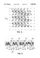
- FIG. 1is a stitch diagram for the first guide bar forming a chain stitch with continuous multifilament fiberglass yarns.
- FIG. 2is a stitch diagram for the second guide bar forming the inlay of continuous multifilament fiberglass yarns and continuous thermoplastic yarns.
- FIG. 3is a stitch diagram combining the stitch diagrams of FIGS. 1 and 2.
- FIG. 4is a schematic illustration showing the bonded areas for cutting a continuous length of the fabric of the present invention into bandages.
- This inventionconcerns a warp-knit casting bandage fabric 9 for use primarily in preparing resin-impregnated orthopedic casts. While described herein as a fabric 9 useful for forming casts, use of such fabric 9 is not so limited. It will be understood by those skilled in the art that such fabric 9 may also be used as a base fabric for a splint, for use as a mold for a prosthetic device or other similar orthopedic uses.
- the fabric 9may be made on a single needle bar warp knitting machine and may be characterized as a single needle, two-bar warp-knit fabric.
- the fabric 9may be made, for example, in the manner described in U.S. Pat. No. 4,745,912 with the exception that only two beams are required for knitting the fabric 9 as distinguished from the three beam construction described therein.
- the fabric 9comprises a first group of a plurality of individual continuous multifilament fiberglass yarns 10 forming lengthwise extending chains of spaced-apart loops.
- the fiberglass yarns 10are preferably those having one turn per inch in the Z direction as used in standard terminology.
- the diameter of the fiberglass yarns 10should be from about 0.00015 inches to about 0.00036 inches, preferably about 0.00025 inches.
- the strand countshould be from about 37 to about 150, preferably 100.
- the fabric 9is also comprised of a second group of a plurality of individual continuous multifilament fiberglass yarns 16, which may be identical to the first group of fiberglass yarns 10.
- the second group of yarns 16is separately interspersed (i.e., in different loops of the lengthwise yarns 10) with a plurality of individual continuous thermoplastic yarns 14 forming a widthwise extending and lengthwise spaced-apart inlay 18.
- the inlay 18is interlaced with the lengthwise chains of spaced-apart fiberglass yarn loops 10.
- thermoplastic yarns 14comprise from about 50% to about 100% of the individual yarns 14, 16 forming said inlay 18.
- the inlay 18comprises a ratio of two thermoplastic yarns 14 to one continuous multifilament fiberglass yarn 16 in the inlay 18. Therefore, the inlay 18 is preferably comprised of about 67% (two-thirds) thermoplastic yarns 14. Two thermoplastic yarns 14 should alternate with a single fiberglass yarn 16 forming the preferred pattern as illustrated in the stitch diagrams depicted in FIGS. 2 and 3.
- the thermoplastic yarns 14 in the inlay 18should have a melting point no greater than 400° F. Preferably the melting point is no greater than 300° F.
- the thermoplastic yarns 14 which are useful for the present fabric 9include, for example, polyolefins, polyamide, polyester, acrylic, acetate, polyvinyl chloride and natural fiber blends thereof.
- the thermoplastic yarn 14 used in the inlay 18has a low melting point to avoid discoloration of the fabric 9 if it is heat bonded. While either textured or non-textured fibers may be used, the most preferred thermoplastic yarn 14 is 300 denier, 72 filament non-textured polypropylene yarn.
- the warp-knit casting fabric 9is woven in a continuous length 26, such as disclosed in U.S. Pat. No. 4,745,912, and impregnated with resin by methods known to those skilled in the art.
- the fabricis resin-impregnated by coating with a polyisocyanate prepolymer composition.
- the compositioncomprises modified diphenylmethane diisocyanate, polypropylene glycol, benzoyl chloride as a stabilizer, and a dimorpholinodiethylether catalyst.
- the benzoyl chloridepreferably comprises from about 0.1 to 1.0% of the composition.
- the preferred ratio of the isocyanate to glycol reactive groups (NCO:OH)is about 4:1.
- foam suppressorssuch as silicone liquids may also be included. It will be understood by those skilled in the art that the fabric may be impregnated or coated with other resin compositions known to those skilled in the art. In addition, it will be understood that other common stabilizers or additives known to those skilled in the art may be substituted in the above described preferred composition without departing from the invention.
- the resin-impregnated, warp-knit fabric 9may then be used to make individual bandages 20 as shown in FIG. 4 having a leading edge 22 and a trailing edge 24 which retain desired flexibility and significantly resist raveling and fraying. It is understood by one skilled in the art that such bandages 20 are cut to size in accordance with their particular orthopedic application.
- the heat-activationforms a narrow bonded area or seal S, which may be made prior to or during cutting the continuous length 26 of fabric 9 into bandages 20, but preferably after the fabric has been resin-impregnated.
- the seal Sshould be about 1/2 inch measured along the longitudinal axis of the continuous length 26 of fabric 9 and should extend transversely from one side of the fabric 9 to the other side.
- the seal Smay also be made by the application of ultrasonic energy.
- the continuous length 26 of fabric 9is cut at pre-bonded positions 28, 30, 32, 34 to create leading and trailing edges 22, 24 by use of a heated apparatus such as a heated metal bar (not shown).
- a heated apparatussuch as a heated metal bar (not shown).
- An example of such an apparatusis a Sentinal heat sealer, available from Sentinal Machinery Division, Hyannis, Mass. It will be understood by one skilled in the art that any heated apparatus which will form a heat-activated bond between the thermoplastic yarns 14 and the fiberglass yarns 10, 16 is acceptable.
- a generally circular rolling knife assemblysimilar to a "pizza cutter," is preferred in order to make a smooth cut through the heat bonded seal S.
- AZCO"Sur-Cut" knife cutter available from the AZCO Corporation, Elmwood Park, N.J. It will be understood by those skilled in the art that any cutting apparatus known in the art such as scissors, knives or scalpels for example may be used to cut the fabric.
- a heated cutting apparatusmay be employed to form the heat-activated seal S and to simultaneously cut the continuous length 26 of fabric 9 into bandages 20 of a desired length L at positions 28, 30, 32, 34.
- the length Lvaries in accordance with the length L required for any given orthopedic application.
- An example of a heated cutting apparatusincludes the AZCO SC-125P heated knife cutter available from AZCO Corporation, Elmwood Park, N.J. It is understood by one skilled in the art that any heated cutting apparatus may be substituted without departing from the spirit of the present invention.
- ultrasonic energymay be used to bond and seal S the thermoplastic yarns 14 to the lengthwise and widthwise extending fiberglass yarns 10, 16.
- the ultrasonic energyis preferably provided by use of an ultrasonic horn "welder" (not shown) such as one manufactured by Sonobond Ultrasonics of West Chester, Pa.
- an ultrasonic horn "welder"such as one manufactured by Sonobond Ultrasonics of West Chester, Pa.
- Sonobond Ultrasonics of West Chester, Pais another example of such an apparatus.
- Branson Ultrasonic Sealeravailable from Branson Ultrasonics, Danbury, Conn.
- thermoplastic yarns 14and the fiberglass yarns 10, 16 at specified positions 28, 30, 32, 34 prior to cutting the continuous length 26 of fabric 9 at those positions to form individual bandages 20.
- Cutting the fabric 9may occur subsequent to or simultaneously with the application of ultrasonic energy in the same manner as described above with respect to the heat-activated bonding and cutting.
- an ultrasonic horn "welder" described aboveis used which cuts and bonds the fabric simultaneously.
- any cutting tool which can simultaneously emit ultrasonic energymay be substituted without departing from the present invention.
- the leading edge 22 of a bandage 20b(as well as the trailing edge 24 of the preceding bandage 20a) is formed by cutting the continuous length 26 of fabric 9, which has preferably first been impregnated with resin, in a direction transverse to the longitudinal axis of the continuous length 26 at a first position 28 where the thermoplastic yarns 14 are bonded to the lengthwise and widthwise extending fiberglass yarns 10, 16. The bond is formed and the cut is made as described above.
- the trailing edge 24 of the same bandage 20b(as well as the leading edge 22 of the following bandage 20c) is formed by cutting the same continuous length 26 of fabric 9 in a transverse direction (generally parallel to the first cut) at a second position 30, spaced apart lengthwise at a distance L from the first position 28, where the thermoplastic yarns 14 are bonded to the lengthwise and widthwise extending fiberglass yarns 10, 16.
- Additional bandages 20may be made by continuing in the same manner as described above, for example, the trailing edge 24 of the bandage 20c (the leading edge 22 of a further bandage 20d) is formed by cutting the continuous length 26 of fabric 9 in a transverse direction (generally parallel to the first and second cuts) at a third position 32, spaced apart lengthwise at a distance L from the second position 30, where the thermoplastic yarns 14 are bonded to the lengthwise and widthwise extending fiberglass yarns 10, 16 (the leading edge 22 of the bandage 20c which is also the trailing edge 24 of bandage 20b is formed as described above).
- the trailing edge of the bandage 20dis then formed by cutting the continuous length 26 of fabric 9 in a like manner at a fourth position 34, a distance L from the third position 32, where the yarns are similarly bonded.
- the present inventionalso comprises a method for forming resin-impregnated, warp-knit casting bandages 20 from the fabric 9 of the present invention.
- a continuous length 26 of the fabric 9, impregnated with resinis subjected to ultrasonic energy as previously described at predetermined positions 28, 30, 32, 34 to bond the thermoplastic yarns 14 to the widthwise and lengthwise extending continuous multifilament fiberglass yarns 10, 16.
- the continuous length 26 of fabric 9is cut at the bonded positions 28, 30, 32, 34 each spaced a longitudinal distance L apart from the next consecutive position forming individual bandages 20 each having a leading edge 22 and a trailing edge 24 in a similar manner as described above for forming the bandages 20 by the application of heat.
- the ultrasonic energymay be applied simultaneously or prior to cutting the continuous length 26 of fabric 9 depending upon the type of apparatus providing the ultrasonic energy as described above.
- a 3 inch wide warp knit fabricwas prepared on a Raschel Knitting machine.
- the fabriccomprised a warp of 100's fiberglass yarn (0.00025 inches in diameter with a strand count of approximately 100) and a fill of polypropylene multifilament yarn (300 denier, 72 filament) (Sample 1).
- This fabric samplewas coated with a polyisocyanate prepolymer comprising diphenylmethane diisocyanate, polypropylene glycol, benzoyl peroxide and dimorpholinodiethylether.
- a Control fabric samplewas prepared on the same Raschel Knitting machine and coated with the same prepolymer. However, the Control contained a warp and fill of entirely 100's fiberglass yarn having the same specifications as the warp yarn of Sample 1.
- Control and Sample 1were both individually subjected to a 400° F. sealing bar at a distance of 4 yards measured lengthwise (i.e., along the longitudinal axis) from the leading edge of each fabric piece forming a 1/2 inch lengthwise segment of stabilized coated web extending widthwise from one side to the other side of each piece of fabric.
- the Control and the Sample 1were subsequently cut at the stabilized segments with a rolling knife assembly, and tested for cast setting time, exotherm, crush strength at 30 minutes, interlayer lamination and cut edge stability and appearance. The test results appear in Table I below.
- a 3 inch wide warp knit fabricwas prepared on a Raschel Knitting machine.
- the fabriccomprised a warp of 100's fiberglass yarn (0.00025 inches in diameter with a strand count of approximately 100) and a fill of 50% polypropylene multifilament yarn (300 denier, 72 filament) and 50% of the same fiberglass yarn as present in the warp.
- the polypropylene and the fiberglass yarnswere individually alternated in the fill inlay (Sample 2).
- Example 1This fabric was coated with the same prepolymer composition as that described in Example 1. Sample 2 was then subjected to a 400° F. heated sealing bar and cut by the same procedure set forth in Example 1. The cut edges were not well stabilized and were considered to be only slightly improved in appearance and stability when compared to the all fiberglass fabric Control sample of Example 1.
- a 3 inch wide warp knit fabricwas prepared on a Raschel Knitting machine.
- the fabriccomprised a warp of 100's fiberglass yarns (0.00025 inches in diameter with a strand count of approximately 100) and a fill of two-thirds polypropylene multifilament yarn (300 denier, 72 filament) and one-third of the same fiberglass yarn as present in the warp (Sample 3). Two polypropylene yarns were alternated with each individual fiberglass yarn in the fill inlay.
- Sample 3was coated with prepolymer and then subjected to a 400° F. heated sealing bar and cut by the same procedure set forth in Example 1. Further, another 4 yard length of the above coated fabric was cut and sealed with an ultrasonic horn "welder" manufactured by Sonobond Ultrasonics, West Chester, Pa. (Sample 4). The two lengths of Samples 3 and 4 were then cut and tested in accordance with the tests outlined in Example 1. The results appear in Table II below.
- Samples 3 and 4each having two polypropylene yarns alternated with each individual fiberglass yarn in the fill inlay, show an increased crush strength over the all fiberglass Control.
- the other properties of Samples 3 and 4 demonstrated by the test resultsare comparable to those of fiberglass.
- Samples 3 and 4demonstrate a substantial improvement in stability and appearance of their cut edges over the cut edges of the all fiberglass Control, thereby showing a high resistance to raveling and fraying.
Landscapes
- Engineering & Computer Science (AREA)
- Textile Engineering (AREA)
- Health & Medical Sciences (AREA)
- Life Sciences & Earth Sciences (AREA)
- Heart & Thoracic Surgery (AREA)
- Vascular Medicine (AREA)
- Biomedical Technology (AREA)
- Animal Behavior & Ethology (AREA)
- General Health & Medical Sciences (AREA)
- Public Health (AREA)
- Veterinary Medicine (AREA)
- Materials For Medical Uses (AREA)
- Knitting Of Fabric (AREA)
- Prostheses (AREA)
Abstract
Description
TABLE I ______________________________________ Sample 1 Control ______________________________________ Cast Setting Time (min.) 3.75 3.50 Exotherm (°F.) 86 98 Crush Strength at 30 min. (lbs.) 88 109 Interlayer Lamination (lbs.) 54 46.5 Cut Edge Stability excellent poor Cut Edge Appearance excellent poor ______________________________________
TABLE II ______________________________________ Sample 3 Sample 4 (rolling cut) (ultrasonic) Control ______________________________________ Cast Setting Time 3.50 3.50 3.50 (min.) Exotherm (°F.) 95 95 98 Crush Strength at 30 min. 138 138 109 (lbs.) Interlayer Lamination 61 61 46.5 (lbs.) Cut Edge Stability excellent excellent poor Cut Edge Appearance excellent excellent poor ______________________________________
Claims (17)
Priority Applications (14)
| Application Number | Priority Date | Filing Date | Title |
|---|---|---|---|
| US08/098,535US5445599A (en) | 1993-07-28 | 1993-07-28 | Warp-knit casting bandage fabric, warp-knit casting bandage and method for making bandage |
| KR1019960700393AKR100317795B1 (en) | 1993-07-28 | 1994-07-09 | Method for manufacturing warp knitted cast bandage fabric, warp knitted cast bandage |
| DE69413982TDE69413982T2 (en) | 1993-07-28 | 1994-07-09 | CHAIN-KNITTED SUPPORT ASSEMBLY, CHAIN-KNITTED SUPPORT ASSEMBLY AND METHOD FOR THE PRODUCTION OF SUPPORT ASSEMBLY |
| EP94924730AEP0708851B1 (en) | 1993-07-28 | 1994-07-09 | Warp-knit casting bandage fabric, warp-knit casting bandage and method for making bandage |
| ES94924730TES2124904T3 (en) | 1993-07-28 | 1994-07-09 | MESH WARP FABRIC FOR PLASTER BANDAGES, MESH PLATTER BANDAGE AND METHOD FOR MANUFACTURING A BANDAGE. |
| PCT/EP1994/002254WO1995004178A1 (en) | 1993-07-28 | 1994-07-09 | Warp-knit casting bandage fabric, warp-knit casting bandage and method for making bandage |
| CA 2165653CA2165653C (en) | 1993-07-28 | 1994-07-09 | Warp-knit casting bandage fabric, warp-knit casting bandage and method for making bandage |
| JP50552195AJPH09500802A (en) | 1993-07-28 | 1994-07-09 | Warp braided bandage fabric, warp braided bandage and method of making bandage |
| DK94924730TDK0708851T3 (en) | 1993-07-28 | 1994-07-09 | Chain knit cast band fabric, chain knit cast bandages and method of making bandages |
| AU74919/94AAU678047B2 (en) | 1993-07-28 | 1994-07-09 | Warp-knit casting bandage fabric, warp-knit casting bandage and method for making bandage |
| AT94924730TATE172256T1 (en) | 1993-07-28 | 1994-07-09 | CHAIN KNITTED SUPPORT BANDAGE, CHAIN KNITTED SUPPORT BANDAGE AND METHOD FOR PRODUCING SUPPORT BANDAGE |
| CZ96249ACZ285767B6 (en) | 1993-07-28 | 1994-07-09 | Warp-knit fabric for solid bandages and process for making elongated solid bandage |
| PL94312467APL177256B1 (en) | 1993-07-28 | 1994-07-09 | Warp knit fabric of a bandage for fixed dressing, a bandage of warp knit fabric for fixed dressing, and a method of manufacturing a bandage |
| NO960334ANO317130B1 (en) | 1993-07-28 | 1996-01-26 | Warp jersey casting bandage, warp jersey casting bandage and method of making bandage |
Applications Claiming Priority (1)
| Application Number | Priority Date | Filing Date | Title |
|---|---|---|---|
| US08/098,535US5445599A (en) | 1993-07-28 | 1993-07-28 | Warp-knit casting bandage fabric, warp-knit casting bandage and method for making bandage |
Publications (1)
| Publication Number | Publication Date |
|---|---|
| US5445599Atrue US5445599A (en) | 1995-08-29 |
Family
ID=22269731
Family Applications (1)
| Application Number | Title | Priority Date | Filing Date |
|---|---|---|---|
| US08/098,535Expired - LifetimeUS5445599A (en) | 1993-07-28 | 1993-07-28 | Warp-knit casting bandage fabric, warp-knit casting bandage and method for making bandage |
Country Status (14)
| Country | Link |
|---|---|
| US (1) | US5445599A (en) |
| EP (1) | EP0708851B1 (en) |
| JP (1) | JPH09500802A (en) |
| KR (1) | KR100317795B1 (en) |
| AT (1) | ATE172256T1 (en) |
| AU (1) | AU678047B2 (en) |
| CA (1) | CA2165653C (en) |
| CZ (1) | CZ285767B6 (en) |
| DE (1) | DE69413982T2 (en) |
| DK (1) | DK0708851T3 (en) |
| ES (1) | ES2124904T3 (en) |
| NO (1) | NO317130B1 (en) |
| PL (1) | PL177256B1 (en) |
| WO (1) | WO1995004178A1 (en) |
Cited By (20)
| Publication number | Priority date | Publication date | Assignee | Title |
|---|---|---|---|---|
| US5617902A (en)* | 1995-06-26 | 1997-04-08 | The United States Of America As Represented By The Administrator Of The National Aeronautics And Space Administration | Weaving and bonding method to prevent warp and fill distortion |
| US5658650A (en)* | 1993-10-25 | 1997-08-19 | Minnesota Mining And Manufacturing Company | Compacted fabrics for orthopedic casting tapes |
| US5725487A (en)* | 1995-06-07 | 1998-03-10 | Johnson & Johnson Professional, Inc. | Orthopedic casting tape |
| US6159877A (en)* | 1993-01-25 | 2000-12-12 | 3M Innovative Properties Company | Fabric backing for orthopedic support materials |
| US20020055313A1 (en)* | 1999-07-30 | 2002-05-09 | Vedagiri Velpari | Non-heat cleaned fabrics and products including the same |
| US20030078650A1 (en)* | 1996-05-24 | 2003-04-24 | Meadox Medicals, Inc. | Shaped woven tubular soft-tissue prostheses and method of manufacturing the same |
| US20050228488A1 (en)* | 2004-04-12 | 2005-10-13 | Scimed Life Systems, Inc. | Varied diameter vascular graft |
| US20060009721A1 (en)* | 2002-11-25 | 2006-01-12 | Bsn Medical, Inc. | Orthopedic fiberglass bandage with a non-fray substrate |
| US20070055093A1 (en)* | 2005-09-08 | 2007-03-08 | Jean-Marc Beraud | Implantable warp knitted fabric |
| US20070163305A1 (en)* | 2004-07-20 | 2007-07-19 | Baer Angela L | Self-curling knitted sleeve and method of fabrication |
| US20100004744A1 (en)* | 1997-01-02 | 2010-01-07 | Kyphon Sarl | Interspinous process distraction system and method with positionable wing and method |
| US20120328810A1 (en)* | 2010-04-16 | 2012-12-27 | Relats, S.A. | Protective tube |
| US8388679B2 (en) | 2007-01-19 | 2013-03-05 | Maquet Cardiovascular Llc | Single continuous piece prosthetic tubular aortic conduit and method for manufacturing the same |
| US8696741B2 (en) | 2010-12-23 | 2014-04-15 | Maquet Cardiovascular Llc | Woven prosthesis and method for manufacturing the same |
| US20150128653A1 (en)* | 2013-11-08 | 2015-05-14 | Pacific Textiles Limited | Warp knitted fabric and method of manufacturing the same |
| US9987114B2 (en) | 2010-03-24 | 2018-06-05 | Covidien Lp | Combination three-dimensional surgical implant |
| CN112626873A (en)* | 2020-11-12 | 2021-04-09 | 南京伯纳德防护用品有限公司 | Glass fiber warp-knitted medical bandage |
| US11097494B2 (en) | 2019-04-22 | 2021-08-24 | Hunter Douglas Inc. | System and method of using lasers to seal an edge of a covering of an architectural-structure covering |
| WO2022254100A1 (en)* | 2021-06-04 | 2022-12-08 | Afitex International | Geosynthetic consisting of a knitted textile structure, and production method thereof |
| DE102023128354A1 (en)* | 2023-06-15 | 2024-12-19 | GM Global Technology Operations LLC | Systems and methods with lattice structures for connecting parts |
Families Citing this family (4)
| Publication number | Priority date | Publication date | Assignee | Title |
|---|---|---|---|---|
| US5921778A (en)* | 1998-03-19 | 1999-07-13 | Jeneric/Pentron Incorporated | Hybrid woven material for reinforcement of dental restorations |
| US6673727B2 (en) | 2001-02-01 | 2004-01-06 | Ebi, L.P. | Orthopedic casts with controlled flexibility |
| JP5955197B2 (en)* | 2012-10-31 | 2016-07-20 | 株式会社島精機製作所 | Knitting method of knitted fabric |
| JP2018079179A (en)* | 2016-11-18 | 2018-05-24 | ニュー キャスト インダストリー カンパニー リミテッドNew Cast Industry Co., Ltd. | Medical cast |
Citations (5)
| Publication number | Priority date | Publication date | Assignee | Title |
|---|---|---|---|---|
| US4323061A (en)* | 1978-10-04 | 1982-04-06 | Tokyo Eizai Laboratory Co., Ltd. | Stiff supporting bandage |
| US4733545A (en)* | 1987-06-04 | 1988-03-29 | Collins & Aikman Corporation | Ravel resistant warp knit elastic tape and method |
| US4745912A (en)* | 1986-11-21 | 1988-05-24 | Mcmurray Fabrics, Inc. | Orthopedic casting bandage |
| US4748078A (en)* | 1985-12-05 | 1988-05-31 | Sakae Lace Co., Ltd. | Warp knitted lace fabrics |
| US4818316A (en)* | 1987-06-04 | 1989-04-04 | Collins & Aikman Corporation | Method of forming a ravel resistant warp knit elastic tape |
Family Cites Families (1)
| Publication number | Priority date | Publication date | Assignee | Title |
|---|---|---|---|---|
| US4609578A (en)* | 1984-11-06 | 1986-09-02 | Minnesota Mining And Manufacturing Company | Resin-coated extensible heat-set fiberglass knit tape |
- 1993
- 1993-07-28USUS08/098,535patent/US5445599A/ennot_activeExpired - Lifetime
- 1994
- 1994-07-09CACA 2165653patent/CA2165653C/ennot_activeExpired - Fee Related
- 1994-07-09ESES94924730Tpatent/ES2124904T3/ennot_activeExpired - Lifetime
- 1994-07-09AUAU74919/94Apatent/AU678047B2/ennot_activeCeased
- 1994-07-09DEDE69413982Tpatent/DE69413982T2/ennot_activeExpired - Fee Related
- 1994-07-09EPEP94924730Apatent/EP0708851B1/ennot_activeExpired - Lifetime
- 1994-07-09PLPL94312467Apatent/PL177256B1/enunknown
- 1994-07-09ATAT94924730Tpatent/ATE172256T1/ennot_activeIP Right Cessation
- 1994-07-09JPJP50552195Apatent/JPH09500802A/ennot_activeCeased
- 1994-07-09DKDK94924730Tpatent/DK0708851T3/enactive
- 1994-07-09CZCZ96249Apatent/CZ285767B6/ennot_activeIP Right Cessation
- 1994-07-09KRKR1019960700393Apatent/KR100317795B1/ennot_activeExpired - Fee Related
- 1994-07-09WOPCT/EP1994/002254patent/WO1995004178A1/enactiveIP Right Grant
- 1996
- 1996-01-26NONO960334Apatent/NO317130B1/ennot_activeIP Right Cessation
Patent Citations (5)
| Publication number | Priority date | Publication date | Assignee | Title |
|---|---|---|---|---|
| US4323061A (en)* | 1978-10-04 | 1982-04-06 | Tokyo Eizai Laboratory Co., Ltd. | Stiff supporting bandage |
| US4748078A (en)* | 1985-12-05 | 1988-05-31 | Sakae Lace Co., Ltd. | Warp knitted lace fabrics |
| US4745912A (en)* | 1986-11-21 | 1988-05-24 | Mcmurray Fabrics, Inc. | Orthopedic casting bandage |
| US4733545A (en)* | 1987-06-04 | 1988-03-29 | Collins & Aikman Corporation | Ravel resistant warp knit elastic tape and method |
| US4818316A (en)* | 1987-06-04 | 1989-04-04 | Collins & Aikman Corporation | Method of forming a ravel resistant warp knit elastic tape |
Cited By (32)
| Publication number | Priority date | Publication date | Assignee | Title |
|---|---|---|---|---|
| US6159877A (en)* | 1993-01-25 | 2000-12-12 | 3M Innovative Properties Company | Fabric backing for orthopedic support materials |
| US5658650A (en)* | 1993-10-25 | 1997-08-19 | Minnesota Mining And Manufacturing Company | Compacted fabrics for orthopedic casting tapes |
| US5725487A (en)* | 1995-06-07 | 1998-03-10 | Johnson & Johnson Professional, Inc. | Orthopedic casting tape |
| US5617902A (en)* | 1995-06-26 | 1997-04-08 | The United States Of America As Represented By The Administrator Of The National Aeronautics And Space Administration | Weaving and bonding method to prevent warp and fill distortion |
| US7550006B2 (en)* | 1996-05-24 | 2009-06-23 | Boston Scientific Scimed, Inc. | Shaped woven tubular soft-tissue prostheses and method of manufacturing the same |
| US20030078650A1 (en)* | 1996-05-24 | 2003-04-24 | Meadox Medicals, Inc. | Shaped woven tubular soft-tissue prostheses and method of manufacturing the same |
| US20100004744A1 (en)* | 1997-01-02 | 2010-01-07 | Kyphon Sarl | Interspinous process distraction system and method with positionable wing and method |
| US6809046B2 (en)* | 1999-07-30 | 2004-10-26 | Ppg Industries Ohio, Inc. | Non-heat cleaned fabrics and products including the same |
| US20020055313A1 (en)* | 1999-07-30 | 2002-05-09 | Vedagiri Velpari | Non-heat cleaned fabrics and products including the same |
| US20060009721A1 (en)* | 2002-11-25 | 2006-01-12 | Bsn Medical, Inc. | Orthopedic fiberglass bandage with a non-fray substrate |
| US20050228488A1 (en)* | 2004-04-12 | 2005-10-13 | Scimed Life Systems, Inc. | Varied diameter vascular graft |
| US7758633B2 (en)* | 2004-04-12 | 2010-07-20 | Boston Scientific Scimed, Inc. | Varied diameter vascular graft |
| US20070163305A1 (en)* | 2004-07-20 | 2007-07-19 | Baer Angela L | Self-curling knitted sleeve and method of fabrication |
| US7395680B2 (en) | 2004-07-20 | 2008-07-08 | Federal Mogul Worldwide, Inc. | Self-curling knitted sleeve and method of fabrication |
| US20070055093A1 (en)* | 2005-09-08 | 2007-03-08 | Jean-Marc Beraud | Implantable warp knitted fabric |
| US8388679B2 (en) | 2007-01-19 | 2013-03-05 | Maquet Cardiovascular Llc | Single continuous piece prosthetic tubular aortic conduit and method for manufacturing the same |
| US10820980B2 (en) | 2010-03-24 | 2020-11-03 | Covidien Lp | Combination three-dimensional surgical implant |
| US9987114B2 (en) | 2010-03-24 | 2018-06-05 | Covidien Lp | Combination three-dimensional surgical implant |
| US9293898B2 (en)* | 2010-04-16 | 2016-03-22 | Relats, S.A. | Protective tube |
| US20120328810A1 (en)* | 2010-04-16 | 2012-12-27 | Relats, S.A. | Protective tube |
| US10682221B2 (en) | 2010-12-23 | 2020-06-16 | Maquet Cardiovascular Llc | Woven prosthesis and method for manufacturing the same |
| US9402753B2 (en) | 2010-12-23 | 2016-08-02 | Maquet Cardiovascular Llc | Woven prosthesis and method for manufacturing the same |
| US10010401B2 (en) | 2010-12-23 | 2018-07-03 | Maquet Cardiovascular Llc | Woven prosthesis and method for manufacturing the same |
| US8696741B2 (en) | 2010-12-23 | 2014-04-15 | Maquet Cardiovascular Llc | Woven prosthesis and method for manufacturing the same |
| US11517417B2 (en) | 2010-12-23 | 2022-12-06 | Maquet Cardiovascular Llc | Woven prosthesis and method for manufacturing the same |
| US20150361603A1 (en)* | 2013-11-08 | 2015-12-17 | Pacific Textiles Limited | Warp knitted fabric and method of manufacturing the same |
| US20150128653A1 (en)* | 2013-11-08 | 2015-05-14 | Pacific Textiles Limited | Warp knitted fabric and method of manufacturing the same |
| US11097494B2 (en) | 2019-04-22 | 2021-08-24 | Hunter Douglas Inc. | System and method of using lasers to seal an edge of a covering of an architectural-structure covering |
| CN112626873A (en)* | 2020-11-12 | 2021-04-09 | 南京伯纳德防护用品有限公司 | Glass fiber warp-knitted medical bandage |
| WO2022254100A1 (en)* | 2021-06-04 | 2022-12-08 | Afitex International | Geosynthetic consisting of a knitted textile structure, and production method thereof |
| FR3123663A1 (en)* | 2021-06-04 | 2022-12-09 | Afitex International | KNITTED TEXTILE STRUCTURE WITH GEOTEXTILE FUNCTION AND METHOD FOR MAKING IT |
| DE102023128354A1 (en)* | 2023-06-15 | 2024-12-19 | GM Global Technology Operations LLC | Systems and methods with lattice structures for connecting parts |
Also Published As
| Publication number | Publication date |
|---|---|
| ATE172256T1 (en) | 1998-10-15 |
| AU7491994A (en) | 1995-02-28 |
| CA2165653A1 (en) | 1995-02-09 |
| DK0708851T3 (en) | 1999-06-23 |
| PL312467A1 (en) | 1996-04-29 |
| CZ24996A3 (en) | 1996-06-12 |
| DE69413982T2 (en) | 1999-04-22 |
| CZ285767B6 (en) | 1999-11-17 |
| NO960334D0 (en) | 1996-01-26 |
| EP0708851B1 (en) | 1998-10-14 |
| NO960334L (en) | 1996-01-26 |
| EP0708851A1 (en) | 1996-05-01 |
| JPH09500802A (en) | 1997-01-28 |
| AU678047B2 (en) | 1997-05-15 |
| CA2165653C (en) | 2003-09-16 |
| WO1995004178A1 (en) | 1995-02-09 |
| KR100317795B1 (en) | 2002-06-20 |
| NO317130B1 (en) | 2004-08-23 |
| PL177256B1 (en) | 1999-10-29 |
| ES2124904T3 (en) | 1999-02-16 |
| DE69413982D1 (en) | 1998-11-19 |
Similar Documents
| Publication | Publication Date | Title |
|---|---|---|
| US5445599A (en) | Warp-knit casting bandage fabric, warp-knit casting bandage and method for making bandage | |
| CA1309911C (en) | Resin-coated extensible heat-set fiberglass knit tape | |
| US4745912A (en) | Orthopedic casting bandage | |
| US3881473A (en) | Ultraviolet light curable orthopedic cast material and method of forming an orthopedic cast | |
| KR0144665B1 (en) | Method of Making Stitch Bonded Elastic Fabric | |
| US7207962B2 (en) | Stretch fabric substrate for medical use | |
| CA1334640C (en) | Conformable bandage | |
| US5461885A (en) | Substrate for retaining a hardenable composition | |
| CA1333870C (en) | Bandages | |
| US5027804A (en) | Bandages | |
| CA2176609C (en) | Orthopedic casting tape | |
| CA1317518C (en) | Self-adhering orthopedic splint | |
| EP0696909B1 (en) | Orthopedic casting tape | |
| NO325575B1 (en) | Orthopedic fiberglass dressing with a non-raking substrate. | |
| KR20190074839A (en) | Medical cushion pad | |
| CA1236807A (en) | Method of manufacturing body protectors | |
| PL25571B1 (en) | Bandage, especially for medicinal purposes, and the method of its manufacture. | |
| CS249616B1 (en) | Flexible warp knit |
Legal Events
| Date | Code | Title | Description |
|---|---|---|---|
| AS | Assignment | Owner name:CARAPACE, INC., OKLAHOMA Free format text:ASSIGNMENT OF ASSIGNORS INTEREST;ASSIGNOR:EDENBAUM, MARTIN;REEL/FRAME:006645/0158 Effective date:19930727 | |
| STPP | Information on status: patent application and granting procedure in general | Free format text:APPLICATION UNDERGOING PREEXAM PROCESSING | |
| FEPP | Fee payment procedure | Free format text:PAYER NUMBER DE-ASSIGNED (ORIGINAL EVENT CODE: RMPN); ENTITY STATUS OF PATENT OWNER: LARGE ENTITY Free format text:PAYOR NUMBER ASSIGNED (ORIGINAL EVENT CODE: ASPN); ENTITY STATUS OF PATENT OWNER: LARGE ENTITY | |
| REMI | Maintenance fee reminder mailed | ||
| FPAY | Fee payment | Year of fee payment:4 | |
| SULP | Surcharge for late payment | ||
| FPAY | Fee payment | Year of fee payment:8 | |
| FPAY | Fee payment | Year of fee payment:12 | |
| AS | Assignment | Owner name:DEROYAL INDUSTRIES, INC., TENNESSEE Free format text:ASSIGNMENT OF ASSIGNORS INTEREST;ASSIGNOR:CARAPACE, INC. (ALSO KNOW AS CARAPACE AND CARAPACE, INCORPORATED);REEL/FRAME:023758/0080 Effective date:20100107 | |
| AS | Assignment | Owner name:BSN MEDICAL, INC., NORTH CAROLINA Free format text:ASSIGNMENT OF ASSIGNORS INTEREST;ASSIGNOR:DEROYAL INDUSTRIES, INC.;REEL/FRAME:023758/0492 Effective date:20100107 | |
| AS | Assignment | Owner name:J.P. MORGAN EUROPE LIMITED, AS AGENT, UNITED KINGD Free format text:MEZZANINE PATENT SECURITY AGREEMENT;ASSIGNOR:BSN MEDICAL INC.;REEL/FRAME:029046/0783 Effective date:20120924 Owner name:J.P. MORGAN EUROPE LIMITED, AS AGENT, UNITED KINGD Free format text:SENIOR PATENT SECURITY AGREEMENT;ASSIGNOR:BSN MEDICAL INC.;REEL/FRAME:029046/0725 Effective date:20120924 | |
| AS | Assignment | Owner name:BSN MEDICAL INC., NORTH CAROLINA Free format text:RELEASE OF MEZZANINE PATENT SECURITY AGREEMENT;ASSIGNOR:J.P. MORGAN EUROPE LIMITED, AS AGENT;REEL/FRAME:042140/0128 Effective date:20170403 Owner name:BSN MEDICAL INC., NORTH CAROLINA Free format text:RELEASE OF SENIOR PATENT SECURITY AGREEMENT;ASSIGNOR:J.P. MORGAN EUROPE LIMITED, AS AGENT;REEL/FRAME:042140/0001 Effective date:20170403 |