US5444880A - Bed with emergency head release and automatic knee down - Google Patents
Bed with emergency head release and automatic knee downDownload PDFInfo
- Publication number
- US5444880A US5444880AUS08/147,166US14716693AUS5444880AUS 5444880 AUS5444880 AUS 5444880AUS 14716693 AUS14716693 AUS 14716693AUS 5444880 AUS5444880 AUS 5444880A
- Authority
- US
- United States
- Prior art keywords
- body section
- bed
- drive
- release
- section
- Prior art date
- Legal status (The legal status is an assumption and is not a legal conclusion. Google has not performed a legal analysis and makes no representation as to the accuracy of the status listed.)
- Expired - Fee Related
Links
- 210000003127kneeAnatomy0.000titleabstractdescription42
- 210000000689upper legAnatomy0.000claimsabstractdescription24
- 230000000977initiatory effectEffects0.000claimsabstractdescription4
- 230000007246mechanismEffects0.000claimsdescription54
- 230000004044responseEffects0.000claimsdescription24
- 230000005484gravityEffects0.000claimsdescription5
- 230000003213activating effectEffects0.000claimsdescription3
- 230000006835compressionEffects0.000description6
- 238000007906compressionMethods0.000description6
- 230000008901benefitEffects0.000description3
- 238000013016dampingMethods0.000description3
- 239000003990capacitorSubstances0.000description2
- 230000000747cardiac effectEffects0.000description2
- 230000008859changeEffects0.000description2
- 238000010586diagramMethods0.000description2
- 230000000694effectsEffects0.000description2
- 239000004677NylonSubstances0.000description1
- 230000004913activationEffects0.000description1
- 230000008878couplingEffects0.000description1
- 238000010168coupling processMethods0.000description1
- 238000005859coupling reactionMethods0.000description1
- 210000003811fingerAnatomy0.000description1
- 230000004048modificationEffects0.000description1
- 238000012986modificationMethods0.000description1
- 230000007935neutral effectEffects0.000description1
- 229920001778nylonPolymers0.000description1
- 230000003068static effectEffects0.000description1
- 210000003813thumbAnatomy0.000description1
Images


Classifications
- A—HUMAN NECESSITIES
- A61—MEDICAL OR VETERINARY SCIENCE; HYGIENE
- A61G—TRANSPORT, PERSONAL CONVEYANCES, OR ACCOMMODATION SPECIALLY ADAPTED FOR PATIENTS OR DISABLED PERSONS; OPERATING TABLES OR CHAIRS; CHAIRS FOR DENTISTRY; FUNERAL DEVICES
- A61G7/00—Beds specially adapted for nursing; Devices for lifting patients or disabled persons
- A61G7/002—Beds specially adapted for nursing; Devices for lifting patients or disabled persons having adjustable mattress frame
- A61G7/015—Beds specially adapted for nursing; Devices for lifting patients or disabled persons having adjustable mattress frame divided into different adjustable sections, e.g. for Gatch position
- Y—GENERAL TAGGING OF NEW TECHNOLOGICAL DEVELOPMENTS; GENERAL TAGGING OF CROSS-SECTIONAL TECHNOLOGIES SPANNING OVER SEVERAL SECTIONS OF THE IPC; TECHNICAL SUBJECTS COVERED BY FORMER USPC CROSS-REFERENCE ART COLLECTIONS [XRACs] AND DIGESTS
- Y10—TECHNICAL SUBJECTS COVERED BY FORMER USPC
- Y10T—TECHNICAL SUBJECTS COVERED BY FORMER US CLASSIFICATION
- Y10T74/00—Machine element or mechanism
- Y10T74/18—Mechanical movements
- Y10T74/18568—Reciprocating or oscillating to or from alternating rotary
- Y10T74/18576—Reciprocating or oscillating to or from alternating rotary including screw and nut
- Y—GENERAL TAGGING OF NEW TECHNOLOGICAL DEVELOPMENTS; GENERAL TAGGING OF CROSS-SECTIONAL TECHNOLOGIES SPANNING OVER SEVERAL SECTIONS OF THE IPC; TECHNICAL SUBJECTS COVERED BY FORMER USPC CROSS-REFERENCE ART COLLECTIONS [XRACs] AND DIGESTS
- Y10—TECHNICAL SUBJECTS COVERED BY FORMER USPC
- Y10T—TECHNICAL SUBJECTS COVERED BY FORMER US CLASSIFICATION
- Y10T74/00—Machine element or mechanism
- Y10T74/18—Mechanical movements
- Y10T74/18856—Oscillating to oscillating
- Y10T74/1888—Geared connections
Definitions
- the present inventionrelates generally to the area of beds in which upper and lower body sections of a user are independently supported by adjustable articulated bed sections, and more particularly, to a bed in which the bed sections are automatically moved to an approximately coplanar position in response to a single discrete manual actuation of a control device.
- Hospital beds having independently moveable articulated head, knee and foot sectionsare well known.
- the articulated bed sectionsare connected to drive mechanisms independently powered by electric motors.
- the bedscontain pushbuttons or other input devices which may be used to operate the motors in different combinations to achieve a desired configuration of the articulated sections.
- U.S. Pat. No. 4,559,655discloses a hospital bed in which the articulated head and knee sections of the bed are connected to independent drive mechanisms and motors.
- a manually operated controlis provided for disengaging the head section from its drive thereby permitting the head section to be moved rapidly downward independent of the drive and motor.
- the above devicepositions the upper torso of the patient in the optimum position for immediate treatment in an emergency cardiac situation.
- the devicedoes not control or activate any change of position of the lower torso supported by the knee section of the bed.
- the motor controlling the position of the knee sectionmust be operated by separate manual controls in order to move the articulated thigh and foot sections of the knee section into a position coplanar with the head section.
- the manual controlmust be continuously activated by an operator for the full time the articulated thigh and foot sections are moving. Alternatively, the thigh and foot sections may be manually lowered to the desired coplanar position.
- U.S. Pat. No. 4,953,243provides for an automatic hands-free repositioning of a hospital bed to a full-up flat position upon entry of a coded command by an attendant.
- the coded commandis created by the attendant activating a pre-existing hand switch simultaneously with a pre-existing foot control.
- the attendantactivates the bed-up foot control and the programmed Trendelenburg hand switch.
- the bed controlhas a logic circuit which is responsive to those two commands for simultaneously producing bed-up knee-down and back-down motor command signals. The requirements of a combination of hand and foot commands by the attendant is utilized to prevent the patient from inadvertently inputting the coded command.
- the present inventionin response to a single actuation of a release control, first, automatically disconnects the head section of a hospital bed from its drive to quickly drop the head section to its desired CPR position; and second, automatically moves the thigh and foot sections with their drive motor to their desired positions.
- a bedhas articulated head, thigh and foot sections pivotally connected to each other.
- the head sectionis connected to a motorized upper drive
- the thigh and foot sectionsare connected to a motorized lower drive.
- the bedincludes a manually actuated release mechanism. A single discrete actuation of a manual release control on the release mechanism disconnects the upper drive from the head section thereby freeing the head section to be manually pushed downward and/or pulled downward by gravity.
- the release mechanismincludes a switch which responds to actuation of the release mechanism to automatically command the lower drive to move the thigh and foot sections into an approximate coplanar relationship with the head section. The switch simultaneously commands the upper drive to reconnect the upper drive to the head section.
- the present inventionhas the advantage using a single control to quickly provide a flat head section and automatically provide a fully flat bed with a single discrete actuation of the single control. Further, rapidly moving the head, knee and foot sections to a coplanar position allows immediate orientation of the bed into the Trendelenburg position, if desired.
- FIG. 1is a side elevation view illustrating a hospital bed with both the upper and lower body sections raised.
- FIG. 2is a side elevation view illustrating a hospital bed with the upper body section lowered and the lower body section raised.
- FIG. 3is a partial side elevation view illustrating a hospital bed with both the upper and lower body sections lowered to a flat horizontal position.
- FIG. 4is a partial top plan view of the hospital bed illustrating the release controls and drives.
- FIG. 5is a cross-sectional view taken along line 5--5 of FIG. 4 and illustrates a partial side view of the upper body drive section engaged with the release mechanism.
- FIG. 6is a view similar to FIG. 5 and illustrates a partial side view of the upper body drive nut disengaged from the release mechanism.
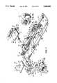
- FIG. 7is a perspective view partially disassembled and illustrating the release controls and the upper body drive.
- FIG. 7Ais an enlarged view of the encircled portion 7A shown in FIG. 7.
- FIG. 8is a longitudinal cross-sectional view illustrating how the release control disengages the release mechanism from the upper body drive nut.
- FIG. 9is a schematic diagram illustrating the operation of the head and knee motors in response to the operation of the release control
- FIGS. 1-3illustrate a hospital bed employing the present invention.
- the bed 10includes a body support assembly 11 mounted on a base 13.
- the body support assembly 11has a support frame 12 connected to a base 13 by means of mechanical drives 14 and 15 which are connected to motors (not shown).
- the body support assembly 11further includes an upper body section, i.e., head section, 16 having one end 17 pivotally linked to a lower body section, i.e., knee section, 18 which includes a thigh section 19 and a foot section 20.
- the one end 17 of the head sectionis pivotally linked to one end 21 of the thigh section 19, and the other end 22 of the thigh section 19 is pivotally connected to one end 23 of the foot section 20.
- FIG. 1illustrates a typical position for a hospital bed in which the head and knee sections 16 and 18, respectively, are positioned such that a patient is in a reclined position with the head and knees raised.
- an emergencysuch as, for example, an emergency cardiac situation
- FIGS. 4-9illustrate the quick release control utilized with the present invention.
- the head section 16includes an upper body frame member 28 with a cross member 30 having its ends rigidly attached to the upper body frame member 28.
- Each of a pair of torque arms 32, 33have one end rigidly connected to the cross member 30 at points intermediate the ends of the cross member 30.
- the other ends of the torque arms 32, 33are pivotally connected to one end of a pair of upper body drive links 34, 35 by pivot pins 36, 37.
- the other ends of the upper body drive links 34, 35are pivotally connected to the release mechanism 38 by pivot pins 40, 41, thereby pivotally connecting the release mechanism to the upper body section.
- the release mechanism 38has a release block 39 slidably mounted on a top surface 42 of the body support frame 12 which also supports the head drive 24.
- the head drive 24includes a head drive motor 44 coupled to one end of a screw 46.
- the other end of the screw 46is supported by a screw support 48.
- a head drive nut 50is rotatably mounted on the screw 46 and the head drive nut 50 translates to the left or the right, as viewed in FIGS. 4-7, with respect to the longitudinal axis of the screw 46, depending on the direction of rotation of the head drive motor 44.
- the release mechanism 38is releasably connected to the head drive nut 50 by means of a pair of latches 52, 53 having one end pivotally connected to the release block 39.
- the other ends of the latches 52, 53have hooks 54, 55 engaging latch pins 56, 57 connected to each side of the head drive nut 50 such that the latch pins 56, 57 are generally perpendicular to the screw 46.
- the latches 52, 53are mechanically coupled to levers 58, 59, each having one end connected to one end of wires 60, 61 slidably located inside cables 62, 63 secured to the release mechanism.
- an attendantuses one of the two manual release mechanisms, or controls, 64, 65 which are located on opposite sides of the head section as illustrated in FIGS. 4 and 7.
- the manually actuated release control 64is shown disassembled in FIG. 7.
- a mounting plate 66is rigidly connected to the upper body frame member 28.
- a button bar 68is slidably located in a slot 70 of release handle 72.
- a compression spring 73is located between two end posts 74, 75 that have respective tab slots 76, 77 opening toward the top of slot 70, see FIG, 7A,
- the button bar 68is inserted into the slot 70 such that the two tabs 78, 79 on the bottom of the button bar are located in the slots 76, 77, respectively, such that the ends of the compression spring 73 are captured between the tabs 78, 79. Consequently, depression of either of the buttons 80 or 81 laterally moves the button bar 68; and a respective tab 78, 79 compresses the spring 73 against an opposing end post. Therefore, when the pushed button 78, 80 is released, the compression spring 73 slides the button bar 68 back to its neutral or center position between the end posts 74, 75 within the release handle 72.
- the assembly of the button bar 68 and release handle 72is positioned against the bottom side of the mounting plate 66 such that locating pins 82, 84, 86 are slidably positioned within slots 88, 90 and 92 of the mounting plate.
- compression pin 94 on release handle 72is inserted in one end of slot 96 of mounting plate 66.
- a compression spring 98has one end in contact with the compression pin 94 and another end slidably positioned over a tongue 100 of mounting plate 66 to hold the spring 98 in position.
- a top cover 102is secured to the pins 82, 84, 86 by fasteners 104.
- buttons 80, 81for example, with a thumb.
- each of the cables 62, 63is connected to the mounting plates 66, 66 of the release actuators 64, 65, respectively.
- the other ends of the release cables 62, 63are connected to the release mechanism 38 by a clamp 116.
- One end of each of the cable wires 60, 61 within the respective release cables 62, 63are attached to the release handles within the release controls 64, 65, respectively.
- the other ends of the cable wires 60, 61are connected to a bar 118 connected between one end of levers 58, 59.
- the mechanical connection between the levers 58, 59 and latches 52, 53, respectively,are identical; and therefore, only the mechanical linkage between lever 58 and latch 60 will be illustrated in detail. Referring to FIG.
- lever 58is pivotally connected to the housing 120 by pivot pin 122.
- Gear teeth 126 on lever 58mesh with gear teeth 128 on latch 52.
- a latch 52is pivotally connected to the housing 120 by pivot pin 130. Consequently, when either of the cable wires 60, 61 pull the bar 118, the lever 58 rotates about pivot pin 122. Gear teeth 126 mesh with gear teeth 128 and cause latch 52 to rotate about the pivot pin 130. That rotation lifts the hook 54 off the latch pin 56 thereby disengaging the release mechanism 38 from the drive nut 50.
- the motion of bar 118causes simultaneous rotation of levers 58, 59 and latches 52, 53 to simultaneously move the hooks 54, 55 away from the latch pins 56, 57, thereby disconnecting the head section from the upper drive.
- motion of the bar 118stretches tension spring 129. After the attendant releases the release controls 64, 65, tension spring 129 pulls levers 58, 59 and hooks 54, 55 back toward the pins 56, 57 to the position illustrated in
- the head section 16quickly achieves the flat position illustrated in FIG. 2.
- the thigh section 19 and foot section 20still have an inclined posture which raises the knee section 18 of the bed 10.
- the release block 39upon being released from the head drive nut 50, the release block 39 has nylon shoes 135, 136 on the bottom of each side of the release mechanism which slide along the top surface 42 of the body support frame 12.
- the sliding motion of the release block 39is directed by a pair of opposed guide rails 138, 139.
- the release block 39operates a release switch 140 which automatically initiates the operation of the knee drive motor 142 and the head drive motor 44.
- Operation of the knee drive motor 142causes the knee drive 26 to move the knee section 18 downward until the thigh section 19 and foot section 20 are in their flat positions coplanar with the head section 16.
- Operation of the head drive motor 44rotates the screw 46 to move the head drive nut 50 toward the right as viewed in FIG. 6 until it reconnects with the release mechanism 38.
- the head drive nut 50moves toward release mechanism 38 until the hooks 54, 55 of latches 52, 53 engage their respective latch pins 56, 57 of the head drive nut 50.
- the head and knee sections 16 and 18, respectivelyhave been automatically lowered to their flat, coplanar position as illustrated in FIG. 3; and the head drive has been automatically reconnected with the head section.
- the entire bed lowering cycleoccurred in response to a single actuation of the quick release control by an attendant.
- FIG. 9is a schematic diagram illustrating a switching circuit 149 for automatically commanding the operation of the head and knee drive motors, 44 and 142, respectively in response to actuation of the quick release control.
- Normally closed contacts 150 in a head down limit switch 152are located within the switch housing 154 of FIG. 7.
- the switch housing 154contains several limit switches to detect the travel of the head drive nut 50 along the screw 46.
- the switch housing 54contains upper travel limit contacts to detect when the head drive nut 50 has raised the head section 16 to the maximum permissible elevation.
- the switch housing 154has a head down limit switch 152 which detects when the head section 16 is in its lowermost position.
- Other drive systems on the hospital bed, for example, knee drive 26also a respective switch housing to detect the upper and lower limits of motion of the knee section 18.
- the head section 16is in an elevated position. Therefore, the head down limit switch 152 is not activated, and the normally closed contacts 150 are closed. At that time, the release switch 140 is not actuated, and the normally open contacts 156 within release switch 140 are open.
- the release mechanism 38is disengaged from the head drive nut 50 and slides over the top surface 42 until it reaches the end of its travel, at which point, it actuates release switch 140 thereby closing normally opened contacts 156. Current then flows from the power source 158 through a time delay network 160 and provides a head and knee drive command signal on an input 162 of motor control 164.
- the time delay circuit 160provides a 1200 millisecond delay which at this point has no discernable effect on the operation of the system.
- output signalsare produced on lines 166 and 168 which are effective to operate the head and knee drive motors 44 and 142 respectively.
- the command signal on line 162functions as a trigger to initiate operation of the motors 44, 142; however, their continued operation and stopping are independent of the continued presence of the command signal on input 162.
- Operation of the head drive motor 44moves the head drive nut 50 along screw 46 back into engagement with the release mechanism 38.
- the head drive nut 50operates the head down limit switch 152 which opens the normally closed contacts 150 and removes the head and knee drive command signal from input 162 of motor control 164.
- the termination of the head and knee drive command signal on input 162has no effect on the signals on output lines 166, 168 of the motor control.
- the operation of the head drive motor 44 in response to the operation of the head down limit switch 152is controlled by the operation of previously known logic circuitry. For example, when the head drive nut 50 actuates the head down limit switch 152, normally open contacts 180 are closed.
- Closing normally opened contacts 180provides a signal to the motor control 164 which is effective to stop the operation of the head drive motor 44.
- operation of the knee drive motor 142moves the thigh and foot sections 19 and 20 downward to a flat orientation.
- the knee drive nut 184(FIG. 4) actuates a knee down limit switch 186 thereby closing normally open contacts 188. Closure of the contacts 188 provides a knee down limit signal to the motor control 164 which stops operation of the knee drive motor 142.
- the head drive nut 50disengages from the head down limit switch 152 thereby closing normally closed contacts 150.
- a head and knee drive command signalwould be applied to the input 162 of motor control 164.
- the 1200 millisecond time delaywhich is the time required to charge capacitor 172 through resistor 174, provides time for the release mechanism 38 moving with the head drive nut 50 to disengage from the release switch 140.
- a static springresets the release switch 140 thereby opening the normally open contacts 156 before the expiration of the 1200 millisecond delay. Therefore, the head and knee drive command signal is not created on input 162 of motor control 164.
- the capacitor 172subsequently discharges through resistor 176 when the contacts 156 open thereby removing the power supply 158 from the input 162.
- the attendantgrabs a single one of the manual release controls 64, 65, depresses one of the buttons 80, 81 and pulls on release handle 72. That single discrete actuation of the single release control pulls hooks 54, 55 away from pins 40, 41, thereby unlatching release mechanism 38 from the upper drive nut 50 and disconnecting the upper body section 16 from the upper drive 24.
- the upper body sectionis pulled by gravity and moves rapidly in a downward direction until it reaches a flat position; however, motion of the upper body section is dampened by the cylinder 132. As the upper body section moves downward, it actuates a switch which commands the operation of the knee drive motor 142 and the head drive motor 44.
- the operation of the knee drive motormoves the thigh and foot sections to a coplanar position with the head section.
- the operation of the head drive motormoves the head drive nut 50 back into engagement with the release mechanism 38 thereby reconnecting the upper body drive 24 to the upper body section 16.
- the head and chest area of the patientcan be lowered to a position suitable for emergency treatment in as little as 2 seconds.
- the thigh and foot sections 19, 20are automatically lowered into a coplanar position by initiating the operation of the knee drive motor 142.
- the head drive 44is automatically reconnected to the upper body section 16.
- the head sectionin response to the release control 64, 65, the head section is moved to its lowermost position by gravity.
- the head motor 44could be operated at a high speed.
- the disclosed embodimentutilizes a release switch 140 to actuate the knee and head motors simultaneously thereby lowering the knee section 18.
- the motor control 164could respond to a limit switch mounted on the release controls 64, 65 or located elsewhere.
- the release control as illustrated on the end of the head section 16can also be mounted at other locations on the bed.
Landscapes
- Health & Medical Sciences (AREA)
- Nursing (AREA)
- Life Sciences & Earth Sciences (AREA)
- Animal Behavior & Ethology (AREA)
- General Health & Medical Sciences (AREA)
- Public Health (AREA)
- Veterinary Medicine (AREA)
- Invalid Beds And Related Equipment (AREA)
Abstract
Description
Claims (26)
Priority Applications (1)
| Application Number | Priority Date | Filing Date | Title |
|---|---|---|---|
| US08/147,166US5444880A (en) | 1993-11-03 | 1993-11-03 | Bed with emergency head release and automatic knee down |
Applications Claiming Priority (1)
| Application Number | Priority Date | Filing Date | Title |
|---|---|---|---|
| US08/147,166US5444880A (en) | 1993-11-03 | 1993-11-03 | Bed with emergency head release and automatic knee down |
Publications (1)
| Publication Number | Publication Date |
|---|---|
| US5444880Atrue US5444880A (en) | 1995-08-29 |
Family
ID=22520523
Family Applications (1)
| Application Number | Title | Priority Date | Filing Date |
|---|---|---|---|
| US08/147,166Expired - Fee RelatedUS5444880A (en) | 1993-11-03 | 1993-11-03 | Bed with emergency head release and automatic knee down |
Country Status (1)
| Country | Link |
|---|---|
| US (1) | US5444880A (en) |
Cited By (47)
| Publication number | Priority date | Publication date | Assignee | Title |
|---|---|---|---|---|
| EP0839508A1 (en) | 1996-10-23 | 1998-05-06 | Hill-Rom, Inc. | Procedural stretcher recline controls |
| US5774914A (en)* | 1996-01-05 | 1998-07-07 | Stryker Corporation | Maternity bed |
| US6000077A (en)* | 1998-07-14 | 1999-12-14 | Cyr; David R. | Single motor fully adjustable bed |
| US6352240B1 (en) | 1999-05-13 | 2002-03-05 | Hill-Rom Services, Inc. | Hydraulic control apparatus for a hospital bed |
| US6615777B2 (en)* | 2001-04-26 | 2003-09-09 | Ina-Schaeffler Kg | Electrically rotatable shaft |
| EP1346669A1 (en)* | 2002-03-18 | 2003-09-24 | Paramount Bed Company Limited | Method of adjustment of a base structure for a bed or the like |
| US6643873B2 (en) | 2001-04-27 | 2003-11-11 | Hill-Rom Services, Inc. | Patient support apparatus having auto contour |
| US20040020708A1 (en)* | 2000-04-03 | 2004-02-05 | Szabela William A. | Electric steering apparatus |
| US6691346B2 (en) | 1999-12-29 | 2004-02-17 | Hill-Rom Services, Inc. | Foot controls for a bed |
| US20050283914A1 (en)* | 2004-06-25 | 2005-12-29 | Roussy Richard B | Patient bed with CPR system |
| WO2007054681A1 (en)* | 2005-11-14 | 2007-05-18 | Huntleigh Technology Limited | Bed frame assembly |
| US20070169268A1 (en)* | 2005-12-19 | 2007-07-26 | Stryker Corporation | Hospital bed |
| US20070174965A1 (en)* | 2005-12-19 | 2007-08-02 | Stryker Corporation | Hospital bed |
| US7296312B2 (en) | 2002-09-06 | 2007-11-20 | Hill-Rom Services, Inc. | Hospital bed |
| US7469433B2 (en)* | 2000-06-02 | 2008-12-30 | Hill-Rom Services, Inc. | Patient support with variable length actuator and release mechanism for lowering a sectional support surface |
| US20090031498A1 (en)* | 2007-08-01 | 2009-02-05 | Stryker Corporation | Cpr drop mechanism for a hospital bed |
| US20090044339A1 (en)* | 2007-08-14 | 2009-02-19 | Stryker Corporation | Shearless pivot for bed |
| US20090092344A1 (en)* | 2007-10-04 | 2009-04-09 | Nippon Thompson Co., Ltd. | Small Slider Unit |
| US7523515B2 (en) | 1995-01-03 | 2009-04-28 | Hill-Rom Services, Inc. | Hospital bed and mattress having a retractable foot section |
| US20100050523A1 (en)* | 2008-08-26 | 2010-03-04 | Helms James M | Safety release mechanism for use with a linear motor turning a ball screw |
| US20100064830A1 (en)* | 2008-09-10 | 2010-03-18 | Zeng Wenli | Drive for adjusting parts of seating and reclining furniture |
| US20100107790A1 (en)* | 2007-03-30 | 2010-05-06 | Zentaro Yamaguchi | Linear actuator |
| US8286282B2 (en) | 1995-08-04 | 2012-10-16 | Hill-Rom Services, Inc. | Bed frame and mattress synchronous control |
| US8344860B2 (en) | 2004-08-02 | 2013-01-01 | Hill-Rom Services, Inc. | Patient support apparatus alert system |
| US8400311B2 (en) | 1999-03-05 | 2013-03-19 | Hill-Rom Services, Inc. | Hospital bed having alert light |
| US8464380B2 (en) | 2005-07-08 | 2013-06-18 | Hill-Rom Services, Inc. | Patient support apparatus having alert light |
| US8537008B2 (en) | 2008-09-19 | 2013-09-17 | Hill-Rom Services, Inc. | Bed status indicators |
| DE102013105413A1 (en)* | 2013-05-27 | 2014-11-27 | Logicdata Electronic & Software Entwicklungs Gmbh | Arrangement for adjusting a bed, in particular a head and foot part of the bed, and drive unit |
| US9089459B2 (en) | 2013-11-18 | 2015-07-28 | Völker GmbH | Person support apparatus |
| US20160058639A1 (en)* | 2014-08-27 | 2016-03-03 | Umano Medical Inc. | Systems for patient support surface orientation and displacement |
| US9295598B2 (en) | 2011-12-09 | 2016-03-29 | Stryker Corporation | Patient support backrest release and actuator assembly |
| US9351890B2 (en) | 2013-03-15 | 2016-05-31 | Stryker Corporation | Medical support apparatus |
| US9655798B2 (en) | 2013-03-14 | 2017-05-23 | Hill-Rom Services, Inc. | Multi-alert lights for hospital bed |
| WO2017128025A1 (en)* | 2016-01-25 | 2017-08-03 | 刘湘静 | Multifunctional medical bed using auto-control technique |
| US9833368B2 (en) | 2012-11-01 | 2017-12-05 | Hill-Rom Services, Inc. | Person support apparatus with spring assistance for articulation |
| US10052249B2 (en) | 2004-10-29 | 2018-08-21 | Stryker Corporation | Patient support with improved control |
| EP2911638B1 (en) | 2012-10-29 | 2018-08-22 | Huntleigh Technology Limited | Apparatus and method for providing emergency cpr functionality on a patient support surface |
| US10206836B2 (en) | 2011-11-11 | 2019-02-19 | Hill-Rom Services, Inc. | Bed exit alerts for person support apparatus |
| US20190191890A1 (en)* | 2017-12-27 | 2019-06-27 | Apex Health Care Mfg. Inc. | Electric Bed with Independent Adjusting Device for Waist Rest |
| US10463892B2 (en)* | 2014-09-18 | 2019-11-05 | Rosenbauer International Ag | Rescue cage, and hoisting rescue vehicle equipped therewith |
| US10729246B2 (en) | 2017-12-21 | 2020-08-04 | Stryker Corporation | Person support apparatus with shear-reducing pivot assembly |
| US20210282566A1 (en)* | 2015-06-19 | 2021-09-16 | Tempur World, Llc | Adjustable Base Assemblies, Systems, and Related Methods |
| US11246776B2 (en) | 2005-12-19 | 2022-02-15 | Stryker Corporation | Patient support with improved control |
| US11376177B2 (en)* | 2013-02-05 | 2022-07-05 | Hill-Rom Services, Inc. | Powered width expansion of articulated bed deck |
| US20220248862A1 (en)* | 2021-02-11 | 2022-08-11 | Hhc Changzhou Corporation | Ready to assemble structural system for a bed |
| EP4066805A1 (en)* | 2021-03-31 | 2022-10-05 | Hill-Rom Services, Inc. | Hospital bed cpr activation assembly |
| US20230000258A1 (en)* | 2021-06-30 | 2023-01-05 | Loctek Inc. | Foldable electric bed frame |
Citations (8)
| Publication number | Priority date | Publication date | Assignee | Title |
|---|---|---|---|---|
| US4038709A (en)* | 1975-12-24 | 1977-08-02 | Kerwit Medical Products, Inc. | Dual hydraulic hospital bed |
| US4346487A (en)* | 1980-04-25 | 1982-08-31 | Whittaker Medical Manufacturing Company | Quick release manual type Fowler for hospital stretchers |
| GB2146241A (en)* | 1983-09-12 | 1985-04-17 | Doherty & Sons Limited Edward | Hospital bed |
| US4559655A (en)* | 1982-08-11 | 1985-12-24 | Hill-Rom Company, Inc. | Bed having articulated frame |
| US4953243A (en)* | 1989-08-09 | 1990-09-04 | Amedco Health Care, Inc. | Electronic control with emergency CPR feature for adjustable bed |
| US5129116A (en)* | 1991-07-12 | 1992-07-14 | Hill-Rom Company, Inc. | Operating mechanism for a hospital bed head panel |
| US5161274A (en)* | 1991-02-06 | 1992-11-10 | J Nesbit Evans & Co. Ltd. | Hospital bed with proportional height knee break |
| US5329657A (en)* | 1992-10-21 | 1994-07-19 | Stryker Corporation | Quick release coupling for head section of a hospital bed |
- 1993
- 1993-11-03USUS08/147,166patent/US5444880A/ennot_activeExpired - Fee Related
Patent Citations (8)
| Publication number | Priority date | Publication date | Assignee | Title |
|---|---|---|---|---|
| US4038709A (en)* | 1975-12-24 | 1977-08-02 | Kerwit Medical Products, Inc. | Dual hydraulic hospital bed |
| US4346487A (en)* | 1980-04-25 | 1982-08-31 | Whittaker Medical Manufacturing Company | Quick release manual type Fowler for hospital stretchers |
| US4559655A (en)* | 1982-08-11 | 1985-12-24 | Hill-Rom Company, Inc. | Bed having articulated frame |
| GB2146241A (en)* | 1983-09-12 | 1985-04-17 | Doherty & Sons Limited Edward | Hospital bed |
| US4953243A (en)* | 1989-08-09 | 1990-09-04 | Amedco Health Care, Inc. | Electronic control with emergency CPR feature for adjustable bed |
| US5161274A (en)* | 1991-02-06 | 1992-11-10 | J Nesbit Evans & Co. Ltd. | Hospital bed with proportional height knee break |
| US5129116A (en)* | 1991-07-12 | 1992-07-14 | Hill-Rom Company, Inc. | Operating mechanism for a hospital bed head panel |
| US5329657A (en)* | 1992-10-21 | 1994-07-19 | Stryker Corporation | Quick release coupling for head section of a hospital bed |
Cited By (105)
| Publication number | Priority date | Publication date | Assignee | Title |
|---|---|---|---|---|
| US7523515B2 (en) | 1995-01-03 | 2009-04-28 | Hill-Rom Services, Inc. | Hospital bed and mattress having a retractable foot section |
| US8286282B2 (en) | 1995-08-04 | 2012-10-16 | Hill-Rom Services, Inc. | Bed frame and mattress synchronous control |
| US5774914A (en)* | 1996-01-05 | 1998-07-07 | Stryker Corporation | Maternity bed |
| US6000076A (en)* | 1996-10-23 | 1999-12-14 | Hill-Rom, Inc. | Procedural stretcher recline controls |
| US6226816B1 (en) | 1996-10-23 | 2001-05-08 | Hill-Rom, Inc. | Procedural stretcher recline controls |
| EP1123690A2 (en) | 1996-10-23 | 2001-08-16 | Hill-Rom, Inc. | Procedural stretcher recline controls |
| EP1123690A3 (en)* | 1996-10-23 | 2002-03-27 | Hill-Rom, Inc. | Procedural stretcher recline controls |
| EP0839508A1 (en) | 1996-10-23 | 1998-05-06 | Hill-Rom, Inc. | Procedural stretcher recline controls |
| US6000077A (en)* | 1998-07-14 | 1999-12-14 | Cyr; David R. | Single motor fully adjustable bed |
| US8830070B2 (en) | 1999-03-05 | 2014-09-09 | Hill-Rom Services, Inc. | Hospital bed having alert light |
| US8400311B2 (en) | 1999-03-05 | 2013-03-19 | Hill-Rom Services, Inc. | Hospital bed having alert light |
| US8525682B2 (en) | 1999-03-05 | 2013-09-03 | Hill-Rom Services, Inc. | Hospital bed having alert light |
| US6352240B1 (en) | 1999-05-13 | 2002-03-05 | Hill-Rom Services, Inc. | Hydraulic control apparatus for a hospital bed |
| US20020130286A1 (en)* | 1999-05-13 | 2002-09-19 | Hill-Rom, Inc. | Hydraulic control apparatus for a hospital bed |
| US7171708B2 (en) | 1999-12-29 | 2007-02-06 | Hill-Rom Services, Inc. | Foot controls for a bed |
| US9009893B2 (en) | 1999-12-29 | 2015-04-21 | Hill-Rom Services, Inc. | Hospital bed |
| US6978500B2 (en) | 1999-12-29 | 2005-12-27 | Hill-Rom Services, Inc. | Foot controls for a bed |
| US20040128765A1 (en)* | 1999-12-29 | 2004-07-08 | Hill-Rom Services, Inc. | Foot controls for a bed |
| US10251797B2 (en) | 1999-12-29 | 2019-04-09 | Hill-Rom Services, Inc. | Hospital bed |
| US6691346B2 (en) | 1999-12-29 | 2004-02-17 | Hill-Rom Services, Inc. | Foot controls for a bed |
| US20040020708A1 (en)* | 2000-04-03 | 2004-02-05 | Szabela William A. | Electric steering apparatus |
| US7469433B2 (en)* | 2000-06-02 | 2008-12-30 | Hill-Rom Services, Inc. | Patient support with variable length actuator and release mechanism for lowering a sectional support surface |
| US6615777B2 (en)* | 2001-04-26 | 2003-09-09 | Ina-Schaeffler Kg | Electrically rotatable shaft |
| US6839926B2 (en) | 2001-04-27 | 2005-01-11 | Hill-Rom Services, Inc. | Patient support apparatus having auto contour |
| US6643873B2 (en) | 2001-04-27 | 2003-11-11 | Hill-Rom Services, Inc. | Patient support apparatus having auto contour |
| US20040055088A1 (en)* | 2001-04-27 | 2004-03-25 | Heimbrock Richard H. | Patient support apparatus having auto contour |
| EP1346669A1 (en)* | 2002-03-18 | 2003-09-24 | Paramount Bed Company Limited | Method of adjustment of a base structure for a bed or the like |
| USRE43532E1 (en) | 2002-09-06 | 2012-07-24 | Hill-Rom Services, Inc. | Hospital bed |
| US7506390B2 (en) | 2002-09-06 | 2009-03-24 | Hill-Rom Services, Inc. | Patient support apparatus having controller area network |
| US7406731B2 (en) | 2002-09-06 | 2008-08-05 | Holl-Rom Services, Inc. | Hospital bed |
| US7520006B2 (en) | 2002-09-06 | 2009-04-21 | Hill-Rom Services, Inc. | Hospital bed including moveable foot portion |
| US7296312B2 (en) | 2002-09-06 | 2007-11-20 | Hill-Rom Services, Inc. | Hospital bed |
| US7669263B2 (en) | 2002-09-06 | 2010-03-02 | Hill-Rom Services, Inc. | Mattress assembly including adjustable length foot |
| US7703158B2 (en) | 2002-09-06 | 2010-04-27 | Hill-Rom Services, Inc. | Patient support apparatus having a diagnostic system |
| US7055195B2 (en) | 2004-06-25 | 2006-06-06 | Carroll Hospital Group, Inc. | Patient bed with CPR system |
| US20050283914A1 (en)* | 2004-06-25 | 2005-12-29 | Roussy Richard B | Patient bed with CPR system |
| US8344860B2 (en) | 2004-08-02 | 2013-01-01 | Hill-Rom Services, Inc. | Patient support apparatus alert system |
| US11382813B2 (en) | 2004-10-29 | 2022-07-12 | Stryker Corporation | Patient support with improved control |
| US9126571B2 (en) | 2004-10-29 | 2015-09-08 | Stryker Corporation | Hospital bed |
| US10052249B2 (en) | 2004-10-29 | 2018-08-21 | Stryker Corporation | Patient support with improved control |
| US20110231996A1 (en)* | 2004-10-29 | 2011-09-29 | Stryker Corporation | Hospital bed |
| US8464380B2 (en) | 2005-07-08 | 2013-06-18 | Hill-Rom Services, Inc. | Patient support apparatus having alert light |
| US9220650B2 (en) | 2005-07-08 | 2015-12-29 | Hill-Rom Services, Inc. | Patient support apparatus having alert light |
| US10561550B2 (en) | 2005-07-08 | 2020-02-18 | Hill-Rom Services, Inc. | Patient support apparatus having alert light |
| US8393026B2 (en) | 2005-11-07 | 2013-03-12 | Stryker Corporation | Hospital bed |
| WO2007054681A1 (en)* | 2005-11-14 | 2007-05-18 | Huntleigh Technology Limited | Bed frame assembly |
| US20070169268A1 (en)* | 2005-12-19 | 2007-07-26 | Stryker Corporation | Hospital bed |
| US7962981B2 (en) | 2005-12-19 | 2011-06-21 | Stryker Corporation | Hospital bed |
| US20110162141A1 (en)* | 2005-12-19 | 2011-07-07 | Stryker Corporation | Hospital bed |
| US9555778B2 (en) | 2005-12-19 | 2017-01-31 | Stryker Corporation | Patient support apparatus with braking system |
| US20070174965A1 (en)* | 2005-12-19 | 2007-08-02 | Stryker Corporation | Hospital bed |
| US8006332B2 (en) | 2005-12-19 | 2011-08-30 | Stryker Corporation | Hospital bed |
| US8701229B2 (en) | 2005-12-19 | 2014-04-22 | Stryker Corporation | Hospital bed |
| US11246776B2 (en) | 2005-12-19 | 2022-02-15 | Stryker Corporation | Patient support with improved control |
| US8402854B2 (en)* | 2007-03-30 | 2013-03-26 | Mitsuba Corporation | Linear actuator |
| US20100107790A1 (en)* | 2007-03-30 | 2010-05-06 | Zentaro Yamaguchi | Linear actuator |
| US20090031498A1 (en)* | 2007-08-01 | 2009-02-05 | Stryker Corporation | Cpr drop mechanism for a hospital bed |
| US7836531B2 (en) | 2007-08-01 | 2010-11-23 | Stryker Corporation | CPR drop mechanism for a hospital bed |
| US20090044339A1 (en)* | 2007-08-14 | 2009-02-19 | Stryker Corporation | Shearless pivot for bed |
| US7913336B2 (en) | 2007-08-14 | 2011-03-29 | Stryker Corporation | Shearless pivot for bed |
| US20090092344A1 (en)* | 2007-10-04 | 2009-04-09 | Nippon Thompson Co., Ltd. | Small Slider Unit |
| US8061227B2 (en)* | 2007-10-04 | 2011-11-22 | Nippon Thompson Co., Ltd. | Small slider unit |
| US20100050523A1 (en)* | 2008-08-26 | 2010-03-04 | Helms James M | Safety release mechanism for use with a linear motor turning a ball screw |
| US20100064830A1 (en)* | 2008-09-10 | 2010-03-18 | Zeng Wenli | Drive for adjusting parts of seating and reclining furniture |
| US7963181B2 (en)* | 2008-09-10 | 2011-06-21 | Man Wah Furniture Manufacturing (Huizhou) Co., Ltd. | Drive for adjusting parts of seating and reclining furniture |
| US8847756B2 (en) | 2008-09-19 | 2014-09-30 | Hill-Rom Services, Inc. | Bed status indicators |
| US8537008B2 (en) | 2008-09-19 | 2013-09-17 | Hill-Rom Services, Inc. | Bed status indicators |
| US8593284B2 (en) | 2008-09-19 | 2013-11-26 | Hill-Rom Services, Inc. | System and method for reporting status of a bed |
| US10206836B2 (en) | 2011-11-11 | 2019-02-19 | Hill-Rom Services, Inc. | Bed exit alerts for person support apparatus |
| US9295598B2 (en) | 2011-12-09 | 2016-03-29 | Stryker Corporation | Patient support backrest release and actuator assembly |
| EP2911638B1 (en) | 2012-10-29 | 2018-08-22 | Huntleigh Technology Limited | Apparatus and method for providing emergency cpr functionality on a patient support surface |
| US9833368B2 (en) | 2012-11-01 | 2017-12-05 | Hill-Rom Services, Inc. | Person support apparatus with spring assistance for articulation |
| US20220287895A1 (en)* | 2013-02-05 | 2022-09-15 | Hill-Rom Services, Inc. | Belt driven width expansion of a bed |
| US11376177B2 (en)* | 2013-02-05 | 2022-07-05 | Hill-Rom Services, Inc. | Powered width expansion of articulated bed deck |
| US10918546B2 (en) | 2013-03-14 | 2021-02-16 | Hill-Rom Services, Inc. | Multi-alert lights for hospital bed |
| US10709625B2 (en) | 2013-03-14 | 2020-07-14 | Hill-Rom Services, Inc. | Foot end alert display for hospital bed |
| US12186249B2 (en) | 2013-03-14 | 2025-01-07 | Hill-Rom Services, Inc. | Multi-alert lights for hospital bed |
| US10413465B2 (en) | 2013-03-14 | 2019-09-17 | Hill-Rom Services, Inc. | Multi-alert lights for hospital bed |
| US9655798B2 (en) | 2013-03-14 | 2017-05-23 | Hill-Rom Services, Inc. | Multi-alert lights for hospital bed |
| US11464692B2 (en) | 2013-03-14 | 2022-10-11 | Hill-Rom Services, Inc. | Multi-alert lights for hospital bed |
| US10512574B2 (en) | 2013-03-14 | 2019-12-24 | Hill-Rom Services, Inc. | Multi-alert lights for hospital bed |
| US11833090B2 (en) | 2013-03-14 | 2023-12-05 | Hill-Rom Services, Inc. | Multi-alert lights for hospital bed |
| US9351890B2 (en) | 2013-03-15 | 2016-05-31 | Stryker Corporation | Medical support apparatus |
| DE102013105413B4 (en)* | 2013-05-27 | 2018-05-09 | Logicdata Electronic & Software Entwicklungs Gmbh | Arrangement for adjusting a bed, in particular a head and foot part of the bed, and drive unit |
| DE102013105413A1 (en)* | 2013-05-27 | 2014-11-27 | Logicdata Electronic & Software Entwicklungs Gmbh | Arrangement for adjusting a bed, in particular a head and foot part of the bed, and drive unit |
| US9089459B2 (en) | 2013-11-18 | 2015-07-28 | Völker GmbH | Person support apparatus |
| US20160058639A1 (en)* | 2014-08-27 | 2016-03-03 | Umano Medical Inc. | Systems for patient support surface orientation and displacement |
| US20190336365A1 (en)* | 2014-08-27 | 2019-11-07 | Umano Medical Inc. | Support panel pivoting system for a patient support device |
| US10426679B2 (en)* | 2014-08-27 | 2019-10-01 | Umano Medical Inc. | Systems for patient support surface orientation and displacement |
| US11229563B2 (en)* | 2014-08-27 | 2022-01-25 | Umano Medical Inc. | Support panel pivoting system for a patient support device |
| US11938069B2 (en) | 2014-08-27 | 2024-03-26 | Umano Medical Inc. | Support panel pivoting system for a patient support device |
| US10463892B2 (en)* | 2014-09-18 | 2019-11-05 | Rosenbauer International Ag | Rescue cage, and hoisting rescue vehicle equipped therewith |
| US20210282566A1 (en)* | 2015-06-19 | 2021-09-16 | Tempur World, Llc | Adjustable Base Assemblies, Systems, and Related Methods |
| US12042050B2 (en)* | 2015-06-19 | 2024-07-23 | Tempur World, Llc | Adjustable base assemblies, systems, and related methods |
| WO2017128025A1 (en)* | 2016-01-25 | 2017-08-03 | 刘湘静 | Multifunctional medical bed using auto-control technique |
| US10729246B2 (en) | 2017-12-21 | 2020-08-04 | Stryker Corporation | Person support apparatus with shear-reducing pivot assembly |
| US10786087B2 (en)* | 2017-12-27 | 2020-09-29 | Apex Health Care Mfg. Inc. | Electric bed with independent adjusting device for waist rest |
| US20190191890A1 (en)* | 2017-12-27 | 2019-06-27 | Apex Health Care Mfg. Inc. | Electric Bed with Independent Adjusting Device for Waist Rest |
| US20220248862A1 (en)* | 2021-02-11 | 2022-08-11 | Hhc Changzhou Corporation | Ready to assemble structural system for a bed |
| US12022954B2 (en)* | 2021-02-11 | 2024-07-02 | Motomotion China Corporation | Ready to assemble structural system for a bed |
| EP4066805A1 (en)* | 2021-03-31 | 2022-10-05 | Hill-Rom Services, Inc. | Hospital bed cpr activation assembly |
| US20220313513A1 (en)* | 2021-03-31 | 2022-10-06 | Hill-Rom Services, Inc. | Hospital bed cpr activation assembly |
| US12053421B2 (en)* | 2021-03-31 | 2024-08-06 | Hill-Rom Services, Inc. | Hospital bed CPR activation assembly |
| US20230000258A1 (en)* | 2021-06-30 | 2023-01-05 | Loctek Inc. | Foldable electric bed frame |
| US11963618B2 (en)* | 2021-06-30 | 2024-04-23 | Flexispot, Inc. | Foldable electric bed frame |
Similar Documents
| Publication | Publication Date | Title |
|---|---|---|
| US5444880A (en) | Bed with emergency head release and automatic knee down | |
| US6000076A (en) | Procedural stretcher recline controls | |
| US3821821A (en) | Electrically operable hospital bed | |
| EP1214035B1 (en) | Stretcher having a motorized wheel | |
| US4751754A (en) | Dual hydraulic hospital bed with emergency bypass circuit | |
| JP3550095B2 (en) | Wheelchair transmission | |
| US3414324A (en) | Adjustable chair | |
| US4953243A (en) | Electronic control with emergency CPR feature for adjustable bed | |
| US3261031A (en) | Patient handler | |
| US4568132A (en) | Motorized lift mechanism | |
| US4142641A (en) | Transfer mechanism | |
| US3486789A (en) | Adjustable chair | |
| DE69516592T2 (en) | METHOD AND DEVICE FOR MOVING THE DISABLED | |
| US3222693A (en) | Adjustable bed | |
| US20020029419A1 (en) | Apparatus for positioning a patient- support deck | |
| EP0341358B1 (en) | Dual hydraulic hospital bed with emergency bypass circuit | |
| US4222131A (en) | Hook type fowler for hospital stretchers | |
| US4094024A (en) | System for controlling relative movement of portions of a bed | |
| CN107049653B (en) | Self-help type patient's hospital bed | |
| US5076644A (en) | Reclining elevator chair | |
| CN109394446B (en) | Multifunctional physiotherapy bed | |
| DE202016102281U1 (en) | Control system for a bed, in particular a medical bed, for example hospital or nursing bed | |
| CN111880399B (en) | Lifting circuit and lifting device capable of achieving anti-pinch function | |
| CN113712764A (en) | Medical fracture postoperative hanging leg support | |
| CN112154249B (en) | Electric control device for vehicle door |
Legal Events
| Date | Code | Title | Description |
|---|---|---|---|
| AS | Assignment | Owner name:HILL-ROM COMPANY, INC., INDIANA Free format text:ASSIGNMENT OF ASSIGNORS INTEREST;ASSIGNORS:WEISMILLER, MATTHEW W.;WILKER, JOHN R., JR.;ALBERSMEYER, DAVID A.;AND OTHERS;REEL/FRAME:006764/0243 Effective date:19931018 | |
| STCF | Information on status: patent grant | Free format text:PATENTED CASE | |
| FEPP | Fee payment procedure | Free format text:PAYOR NUMBER ASSIGNED (ORIGINAL EVENT CODE: ASPN); ENTITY STATUS OF PATENT OWNER: LARGE ENTITY | |
| REFU | Refund | Free format text:REFUND - PAYMENT OF MAINTENANCE FEE, 4TH YEAR, LARGE ENTITY (ORIGINAL EVENT CODE: R183); ENTITY STATUS OF PATENT OWNER: LARGE ENTITY | |
| FPAY | Fee payment | Year of fee payment:4 | |
| LAPS | Lapse for failure to pay maintenance fees | ||
| FP | Lapsed due to failure to pay maintenance fee | Effective date:19990829 | |
| AS | Assignment | Owner name:HILL-ROM SERVICES, INC., INDIANA Free format text:ASSIGNMENT OF ASSIGNORS INTEREST;ASSIGNOR:HILL-ROM, INC.;REEL/FRAME:011796/0440 Effective date:20010215 | |
| FPAY | Fee payment | Year of fee payment:8 | |
| FPAY | Fee payment | Year of fee payment:12 | |
| FEPP | Fee payment procedure | Free format text:PETITION RELATED TO MAINTENANCE FEES FILED (ORIGINAL EVENT CODE: PMFP); ENTITY STATUS OF PATENT OWNER: LARGE ENTITY |