US5444242A - Scanning and high resolution electron spectroscopy and imaging - Google Patents
Scanning and high resolution electron spectroscopy and imagingDownload PDFInfo
- Publication number
- US5444242A US5444242AUS08/201,912US20191294AUS5444242AUS 5444242 AUS5444242 AUS 5444242AUS 20191294 AUS20191294 AUS 20191294AUS 5444242 AUS5444242 AUS 5444242A
- Authority
- US
- United States
- Prior art keywords
- anode
- specimen surface
- energy
- rastering
- analyzer
- Prior art date
- Legal status (The legal status is an assumption and is not a legal conclusion. Google has not performed a legal analysis and makes no representation as to the accuracy of the status listed.)
- Expired - Lifetime
Links
Images


Classifications
- G—PHYSICS
- G01—MEASURING; TESTING
- G01N—INVESTIGATING OR ANALYSING MATERIALS BY DETERMINING THEIR CHEMICAL OR PHYSICAL PROPERTIES
- G01N23/00—Investigating or analysing materials by the use of wave or particle radiation, e.g. X-rays or neutrons, not covered by groups G01N3/00 – G01N17/00, G01N21/00 or G01N22/00
- G01N23/22—Investigating or analysing materials by the use of wave or particle radiation, e.g. X-rays or neutrons, not covered by groups G01N3/00 – G01N17/00, G01N21/00 or G01N22/00 by measuring secondary emission from the material
- G01N23/227—Measuring photoelectric effect, e.g. photoelectron emission microscopy [PEEM]
- G01N23/2273—Measuring photoelectron spectrum, e.g. electron spectroscopy for chemical analysis [ESCA] or X-ray photoelectron spectroscopy [XPS]
- G—PHYSICS
- G01—MEASURING; TESTING
- G01N—INVESTIGATING OR ANALYSING MATERIALS BY DETERMINING THEIR CHEMICAL OR PHYSICAL PROPERTIES
- G01N23/00—Investigating or analysing materials by the use of wave or particle radiation, e.g. X-rays or neutrons, not covered by groups G01N3/00 – G01N17/00, G01N21/00 or G01N22/00
- G01N23/22—Investigating or analysing materials by the use of wave or particle radiation, e.g. X-rays or neutrons, not covered by groups G01N3/00 – G01N17/00, G01N21/00 or G01N22/00 by measuring secondary emission from the material
- G01N23/227—Measuring photoelectric effect, e.g. photoelectron emission microscopy [PEEM]
- H—ELECTRICITY
- H01—ELECTRIC ELEMENTS
- H01J—ELECTRIC DISCHARGE TUBES OR DISCHARGE LAMPS
- H01J37/00—Discharge tubes with provision for introducing objects or material to be exposed to the discharge, e.g. for the purpose of examination or processing thereof
- H01J37/252—Tubes for spot-analysing by electron or ion beams; Microanalysers
- H01J37/256—Tubes for spot-analysing by electron or ion beams; Microanalysers using scanning beams
- H—ELECTRICITY
- H01—ELECTRIC ELEMENTS
- H01J—ELECTRIC DISCHARGE TUBES OR DISCHARGE LAMPS
- H01J37/00—Discharge tubes with provision for introducing objects or material to be exposed to the discharge, e.g. for the purpose of examination or processing thereof
- H01J37/26—Electron or ion microscopes; Electron or ion diffraction tubes
- H01J37/285—Emission microscopes, e.g. field-emission microscopes
- H—ELECTRICITY
- H01—ELECTRIC ELEMENTS
- H01J—ELECTRIC DISCHARGE TUBES OR DISCHARGE LAMPS
- H01J49/00—Particle spectrometers or separator tubes
- H01J49/44—Energy spectrometers, e.g. alpha-, beta-spectrometers
- H01J49/46—Static spectrometers
- H01J49/48—Static spectrometers using electrostatic analysers, e.g. cylindrical sector, Wien filter
- H—ELECTRICITY
- H01—ELECTRIC ELEMENTS
- H01J—ELECTRIC DISCHARGE TUBES OR DISCHARGE LAMPS
- H01J2237/00—Discharge tubes exposing object to beam, e.g. for analysis treatment, etching, imaging
- H01J2237/25—Tubes for localised analysis using electron or ion beams
- H01J2237/2505—Tubes for localised analysis using electron or ion beams characterised by their application
- H01J2237/2516—Secondary particles mass or energy spectrometry
- H01J2237/2522—Secondary particles mass or energy spectrometry of electrons (ESCA, XPS)
Definitions
- This inventionrelates generally to electron microanalysis and imaging of surfaces, and particularly to high-resolution x-ray scanning photoelectron spectroscopy and imaging, and to an electron lens system for adapting electron energy analyzers for imaging in electron spectrometric instruments.
- chemometric surface analysisis electron spectroscopy for chemical analysis (ESCA) which involves irradiating a sample surface with ultraviolet or preferably x-rays and detecting the characteristic photoelectrons emitted.
- ESAelectron spectroscopy for chemical analysis
- XPSx-ray photoelectron spectroscopy
- the photoelectronsare filtered by an electrostatic or magnetic analyzer which allow only electrons of a specified narrow energy band to pass through to a detector.
- the intensity of the detected beamtypically represents the concentration of a given chemical constituent on or near a specimen surface.
- Electron kinetic energiesare detected or analyzed by magnetic or electrostatic devices that deflect charged particles according to their velocities.
- Electrostatic typesinclude coaxial cylindrical, radial cylindrical and radial hemispherical.
- the Gerlach et al patentdiscloses the coaxial cylindrical analyzer.
- a radial cylindrical analyzeris taught in U.S. Pat. No. 4,764,673 (Bryson et al).
- the Watson patent and U.S. Pat. No. 4,358,680 (Read)describe the electrostatic hemispherical type of analyzer.
- Radial analyzers(cylindrical and hemispherical) generally are preceded by a lens system formed of rings, cylinders and/or grids for adjusting electron energy and focusing the electrons into the analyzer.
- a lens systemformed of rings, cylinders and/or grids for adjusting electron energy and focusing the electrons into the analyzer.
- Such lensesare disclosed in the aforementioned U.S. Pat. Nos. 4,358,680 and 4,764,673.
- the design of such lenses that vary retardation over a moderate range of retardation ratiosis described in an article "Computer Optimization of Retarding Lens Systems for ESCA Spectrometers" by B. Wannberg and A. Skollermo, J. Electron Spectroscopy and Related Phenomena, 10 45-78 (1977).
- These systemsare directed to area analyses using a relatively low solid angle of electron collection, and a wider range of ratios is desirable.
- Another method for analyzing surfacesutilizes secondary Auger electrons generated at a small area of sample surface by a focused primary electron beam.
- Surface mapping of elementsis accomplished by scanning with the primary electron beam.
- An example of a scanning Auger-microprobe utilizing a coaxial cylindrical type of electrostatic electron analyzeris provided in U.S. Pat. No. 4,048,498 (Gerlach et al).
- a more commonly known instrumentis a scanning electron microscope (SEM) in which a focused electron beam is rastered over a specimen surface. Secondary electrons emitted from the surface are detected in correlation with rastering positions. The secondary electron signals are processed electronically to provide a picture or image of topographical features of the surface.
- SEMscanning electron microscope
- An SEM itselfdoes not provide chemometric analysis, although x-ray emissions induced by the incident electrons are used for such analysis.
- Another limitation of the SEMis imaging the surface of electrical insulators, because of rapid charge buildup from the incident beam of electrons. Conductive coatings or other techniques are used to alleviate charging, but at the loss of surface details, time and cost of extra preparation, and loss of ability to remove surface layers during analysis.
- U.S. Pat. No. 5,118,941(Larson), of the present assignee, discloses that insulator specimens can be imaged with a single frame of SEM rastering, but at the expense of resolution.
- Separate detectorsgenerally are used for the analyzing and imaging functions in the same instrument, for example as further disclosed in the Larson patent. This adds cost and employs space which could otherwise be available for other purposes. Also, particularly for low current systems, there is a need for detection of a greater proportion of electrons from the sample for imaging, and for rejecting background from stray electrons, ions and excited neutrals which originate from other sources. For energy analyzers the sample generally is kept field-free, whereas for imaging, a field is applied so as to maximize the quantity of electrons collected by the detector.
- the Larson patentalso discloses a system for locating target area for microanalysis of a specimen surface, using an SEM in conjunction with the microanalyzer. Backscattered electrons from the SEM electron beam are passed through the analyzer for producing a further image that is superimposed on the SEM image, such that the further image represents the target area for microanalysis.
- Rasteringcan be used to provide images or chemical mapping of the surface.
- X-rays from an anode targethave been focused onto the specimen by means of a concave crystal monochrometer, as taught in U.S. Pat. Nos. 3,567,926 (Siegbahn), 3,617,741 (Siegbahn et al), 4,680,467 (Bryson et al), 4,752,685 (Shiokawa et al) and 5,127,028 (Wittry).
- a method of construction of a concave monochrometer for focusing x-raysis disclosed in U.S. Pat. No. 3,772,522 (Hammond et al), in which a quartz crystal disk is brazed with a metal film onto a concave spherical surface of a substrate.
- a number of plateletsmay be bonded to the surface, for example in a monochrometer used in a PHI model 5600 instrument sold by Perkin-Elmer. Bonding techniques include brazing, optical contacting, epoxy and the like. The platelets are cut sequentially from the end of a single crystal rod of quartz.
- a second approach to reduced area analysishas been to use an x-ray beam that floods the specimen surface, combined with a small-area objective lens for the photoelectrons, such as taught in U.S. Pat. No. Re. 33,275 (Wardell et al) for an electrostatic objective lens.
- Direct XPS imaging of a surface flooded with x-raysusing a type of magnetic lens variously known as an immersion lens, single pole piece lens or snorkel lens, as taught in U.S. Pat. Nos. 4,810,880 (Gerlach) and 4,810,879 (Walker).
- Scanning for XPSmay be effected by rastering the sample or the analyzer system mechanically, which is cumbersome. Scanning is also achieved by electronic deflection in the objective lens to receive electrons from off-axis, in a manner as described in an article "A Wide-angle Secondary Ion Probe for Organic Ion Imaging” by C. C. Grimm, R. T. Short, and P. J. Todd, J. Am Soc. Mass. Spectrum 1991, 2, 362-371. Scanning of the objective lens for generating photoelectron images is disclosed in the aforementioned U.S. patent No. 4,752,685, and in an article "AXIS: An Imaging X-Ray Photoelectron Spectrometer" by I. W. Drummond, F. J. Street, L. P. Ogden, and D. J. Surman, SCANNING 13, 149-163 (March-April 1991).
- a higher resolution type of x-ray microscopeutilizes zone plates and mirror techniques. This requires a very intense source of x-rays such as from a synchrotron, and so is not practical for general use.
- An object of the present inventionis to provide an improved instrument for chemometric mapping across a surface area by x-ray photoelectron analysis.
- a specific object for such an instrumentis to provide for compensation of shifts in electron energy across such a surface area.
- Another objectis to provide improved mapping as well as summed-area information for insulators by x-ray photoelectron analysis.
- a further objectis to provide an electron energy analyzer system to serve as a high performance secondary electron detector for imaging.
- Yet another objectis to provide a high performance chemometric analyzer.
- a scanning x-ray instrumentfor analysis of a specimen surface
- the instrumentincludes an electron gun for producing a focused electron beam, and an anode with an anode surface disposed to receive the focused electron beam so as to generate x-rays from an anode spot on the anode surface.
- the electron beamis rastered over the anode surface, thereby scanning the anode spot over the anode surface.
- the x-rays from the scanning anode spotare focused, advantageously by a concave Bragg crystal monochromator, in an energy band of x-rays as an x-ray spot on a pixel area scanning correspondingly over the specimen surface.
- Photoelectronsare thereby emitted from the scanning pixel area with electron energies characteristic of chemical species at the pixel area.
- An analyzer meansis receptive of photoelectrons from the scanning pixel area for analyzing the electron energies.
- the analyzer meansincludes a detector receptive of the photoelectrons for generating corresponding photoelectron signals.
- a processing means receptive of the signalsis cooperative with the rastering means and the analyzer means for generating specimen information representative of the electron energies and thereby chemical species of the specimen surface.
- the x-rays and thereby the photoelectronshave a natural energy shift across the specimen surface.
- a compensating meansis associated with the analyzer means for compensating for the shift.
- the analyzer meanscomprises a hemispherical electrostatic deflector to deflect photoelectrons for detection according to a selected pass energy.
- the analyzerfurther comprises a lens means receptive of electrons from the specimen surface for transitting the electrons to the analyzer means in a pass energy range.
- a selected voltageis applied between the lens means and the deflector, the selected voltage being determinative of the pass energy range.
- the compensating meansthen coordinates the voltage means with the rastering means to correspondingly modulate the selected voltage to compensate for the shift.
- the above-described scanning x-ray instrumentmay be utilized for analysis of an electrically insulating specimen surface.
- the processing meanssums the signals from across the selected area to generate information representative of chemical species summed over the selected area of the specimen surface.
- a blocking meansblocks information of peripheral areas of the selected area from the summing. The rastering should be sufficiently rapid so that charge potential on the pixel area scanning across the specimen surface does not change significantly during x-ray spot dwell time.
- Objectsare also achieved with an instrument for analysis of a specimen surface, wherein the instrument includes beam means for directing an energy beam to a pixel area on a specimen surface so as to emit electrons from the specimen surface.
- the energy beammay be a focused electron beam or a focused x-ray beam such as described above.
- the emitted electronsare in ranges of lower energy, such as 1-10 eV, and higher energy, such as 300-1500 eV.
- the lower energy rangeis representative of features of the specimen surface, and the higher energy range is characteristic of chemical species in the specimen surface.
- the beamis rastered over the specimen surface, thereby scanning the pixel area of emitting electrons over the surface.
- An analyzer meansis receptive of electrons in a pass energy range generally between 3 eV and 300 eV, for producing signals representative of said electrons.
- a lens meansis receptive of electrons from the specimen surface for selectively transitting electrons from the specimen surface to the analyzer means, the lens means modifying energies of the transitted electrons into the pass energy range.
- a control meansselectively controls the lens means to operate in a first mode or a second mode, the first mode being to modify the electron energies from the lower energy range into the pass energy range, and the second mode being to modify the electron energies from the higher energy range into the pass energy range.
- a display meansis receptive of the analyzer signals cooperatively with the rastering means for displaying information associated with the pixel area scanning across the specimen surface. In response to the control means, the information provides an imaging of the specimen surface for the first mode, or a mapping of chemical species in the specimen surface for the second mode.
- the lens meanscomprises a first electrode receptive of electrons from the specimen surface for transitting the electrons, a second electrode spaced coaxially from the first electrode for further transitting the electrons. More preferably, the first electrode and the second electrode are each in the form of a grid that is concave toward the specimen surface.
- An electron focusing meansextends coaxially from the second electrode toward the analyzer for focusing to the analyzer said electrons with energies modified into the pass energy range.
- the control meanscomprises means for applying a first potential to the first electrode, and a second potential to the second electrode. The second potential is negative with respect to the first potential, and the first potential selectively is positive with respect to the specimen for the first mode, and the same potential as the specimen for the second mode.
- the instrumentpreferably further comprises flood means for flooding the specimen surface with low energy electrons during periodic intervals so as to neutralize loss of photoelectrons from the specimen surface.
- the analyzer signalsare omitted from effecting the information during the periodic intervals for the first mode.
- the first potentialis made equal (or positive) with respect to the specimen during the periodic intervals for the first mode.
- FIG. 1is a schematic diagram of an instrument incorporating the invention.
- FIG.2is a longitudinal section of an electron gun used in the instrument of FIG. 1.
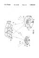
- FIG. 3is a detail in perspective of an anode, a specimen and a monochromator in the instrument of FIG. 1.
- FIG. 4is an elevation of an alternative embodiment for a magnetic lens for the instrument of FIG. 1.
- FIG. 5is a perspective of a crystal member used for forming the monochromator of FIG. 3.
- FIG. 6is a schematic section of a lens component of the instrument of FIG. 1 wherein an imaging detector is omitted.
- FIG. 7is a schematic diagram of an alternative instrument incorporating the lens component of FIG. 6.
- An instrument 10 for analysis of a surface 12 of a sample specimen 14is illustrated schematically in FIG. 1.
- An electron gun 16has an appropriate electron lens system 18 for focusing an electron beam 20 onto the surface 22 of a target anode 24.
- the gunmay be a conventional type, modified to optimize for higher power and larger beam size.
- the electron beam 20should focus to a spot 26 (FIG. 3) on the anode surface, the spot being as small as practical, e.g. down to about 4 microns. This results in the generation of x-rays 27 from the anode, and in particular from the anode spot.
- FIG. 2illustrates a useful electron gun 16.
- a cathode assembly 1with a LaB 6 cathode 2, a wenwelt 3 and a gun anode 4.
- the mid portionincludes an electrostatic condenser lens 5 with a condenser aperture 6.
- a magnetic objective lens 7includes a polepiece 8 and a coil 9. Deflection of the beam is effected with an electrostatic deflector 11.
- the gunis operated at 10 to 20 KV over 1 to 60 watts with a selectable beam size of 4 to 250 microns.
- the anode 24may be formed of any metal such as aluminum that provides a desired x-ray emission energy band; ordinarily the band is substantially a line of small energy width.
- the anodeshould be at or near ground potential, and the gun cathode is operated at a negative voltage, for example -20 KV, with respect to the anode to effect generation of x-rays including the desired band of x-rays of predetermined energy.
- the selected energy bandis the aluminum K-alpha line at 1.4866 KeV.
- Deflection plates 28(one pair shown in FIG. 1) direct the electron beam 20 from the electron gun 16 to the anode spot 26 among an array of such spot locations 32 on the anode surface 22.
- the control 30rasters the focused electron beam 20 across the surface of the anode, thereby scanning the anode spot across the anode surface, and x-rays 27 are emitted from the anode at the scanning anode spot.
- Raster speedis at least 0.5 microseconds per pixel, for example 1 to 10 microseconds.
- a Bragg crystal monochromator 34is disposed to receive a portion of the x-rays 27 from the anode 24.
- the monochromatorhas a crystallographic orientation and a concave configuration 35 to select and focus a beam of x-rays 36 in the desired energy band, e.g. the K-alpha line, as an x-ray spot 38 on the specimen surface 12 to be analyzed.
- the x-ray spot on the specimenis an image of the anode spot 26.
- the specimen 14rests on a stage 40 that may have orthogonal micrometer positioners 42 for manual or motorized positioning with respect to a support 44 in the instrument.
- a Bragg crystal monochromatoris preferred, other focussing means may be suitable. These include grazing incidence mirrors and synthetic multilayer devices of alternating high and low density material (e.g. tungsten and carbon). In each case the reflector is curved in two dimensions to focus the diffracted x-rays onto the specimen.
- a suitable arrangementis based on the conventional Rowland circle 46, in which the anode surface 22, the crystal 34 and the sample surface 12 are substantially on the circle, for example as taught in the aforementioned U.S. Pat. No. 3,772,522.
- the crystalhas a radius of curvature equal to the diameter of the Rowland circle.
- the radius of curvature in the plane orthoganal to the drawingis (2R*cos 2 B) where R is the circle radius and B is the Bragg angle.
- the respective radiiare 50 and 48 cm for quartz cut in a (100) plane, aluminum K-alpha x-rays and a Rowland circle radius of 25 cm.
- the (100) planeis also known as a y-axis plane or a "zero degree y cut".
- Theseare curvatures of the crystal lattice, not ground-in curvatures on the surface.
- the crystalsshould be ellipsoidal.
- the focusing of the energy band of x-rays 36effects the x-ray spot 38 on a selected pixel area 48 of the specimen surface 12 (FIG. 3).
- This pixel areawhich coincides with the x-ray spot, is an x-ray image of the anode spot 26.
- Pixel 48is in an array of such pixel locations 50 corresponding to the array of anode spots 32.
- the selected pixel areathereby corresponds to the selected anode spot, the location of which is determined by selection of voltages on the deflection plates 28 for the electron beam 20.
- the position of the pixel areais effectively selected via these deflection voltages.
- the anode spot locationis continually changing, being each sequential spot location in the array on the anode surface.
- the rastering of the focused beam over the array of anode spotsis such that the x-ray spot is correspondingly rastered over the array of pixel locations 50 covering a desired surface area of the specimen surface.
- the x-rays 36cause photoelectrons 52 to be emitted from the active, scanning pixel area 48 of the specimen.
- the electron kinetic energiesgenerally include a low energy peak in the range of up to 10 ev, usually about 2 to 5 ev, plus higher kinetic energy peaks or lines characteristic of chemical species (viz. chemical elements and/or their electron bondings) in the selected pixel area. With the rastering, characteristic higher energy photoelectrons vary with chemistry across the specimen surface, and the low energy electrons (commonly known as "secondary electrons") vary with topography as well.
- the photoelectron spectrumprovides information on the surface at a selected pixel area or across the rastered array of areas. There also may be Auger electrons which, for the present purpose, are included in the term "photoelectrons" as they are caused by the x-rays.
- Scanning speedmay be between zero (for a selected spot) and 100 m/sec, for example 10 m/sec.
- Time per pixel areamay be about one microsecond, with the mapping and imaging being built up from thousands of frames.
- an electron energy analyzer 54receives a portion of the photoelectrons 52.
- the analyzermay be a known or desired type, generally either magnetic or electrostatic, which deflects the photoelectrons in a predetermined path 68 according to electron energy and thence to a detector 70.
- a selected control signal(either a current or a voltage difference), is applied to the analyzer system to establish the amount of deflection, so that the signal level is representative of selected energy of photoelectrons deflected in the predetermined path.
- a magnetic analyzersuch as a magnetic prism
- a current signal through the magnet coilsis appropriately selected.
- an electrostatic analyzera deflecting voltage signal is selected.
- the electrostatic energy analyzermay be a radial cylindrical type described in the aforementioned U.S. Pat. No. 4,048,498.
- the analyzer 54is a hemispherical type as described in the aforementioned U.S. Pat. No. 3,766,381.
- the analyzing meansalso includes a lens system 56 such as an electrostatic lens for focusing the input to the analyzer.
- the lensusually combines objective and energy modifying functions to collect photoelectrons emitted from the effective pixel area and direct them into the analyzer in a desired pass energy range.
- the electrostatic lens 56may be conventional, for example a PHI Omnifocus IVTM lens of Perkin-Elmer.
- the lensmay include pairs of orthogonal deflection plates 59 with applied voltages from a source 55 (FIG. 4). The voltages on the plates are selected, varied or oscillated via the processor 76 in cooperative synchronization with positioning or rastering of the primary electron beam 20, under control of the processor, to centralize off-axis photoelectrons so that a substantial portion of the electrons reach the slit of stop 84 and enter into the analyzer 54.
- An alternative for the objective lens functionis a magnetic lens 58 (FIG. 4), advantageously of a type variously known as an immersion lens, a single pole piece lens or a snorkel lens as described in the aforementioned U.S. Pat. No. 4,810,880.
- This objective lensis situated below the specimen so that the magnetic field of the lens collects a substantial portion of the emitted photoelectrons 52 from the sample surface.
- the sampleis placed proximate the immersion lens, the sample being interposed between the immersion lens and a separate electrostatic lens 60; in this case lenses 58 and 60 form the lens system 56 (FIG. 1). More generally, the sample is located between the immersion lens and the analyzer.
- the magnetic lenshas a collection field (illustratively delineated by broken lines 61) smaller than the rastered area, off-center emissions may be centered by deflector plates 59. Particularly good collection efficiency and sensitivity are attained with such a system.
- a selected voltage from a voltage source 62applied via lines 69 across the hemispheres 64,66 of the analyzer, electrons of selected energy travel in a range of trajectories 68 so as to exit the analyzer into the detector 70.
- the lattermay be a conventional multichannel detector, for example having 16 channels for detecting a range of electron energies passed by the analyzer in slightly different trajectories.
- a further lens(not shown) may be placed between the analyzer and the detector, if desired or required for certain types of detectors.
- Signals from the detector 70are carried on a line or lines 72 (via an appropriate amplifier, not shown) to an analyzing portion 74 of the processing unit 76 which combines control electronics and computer processing, such as with a Hewlett Packard Model 425e computer.
- the processingconverts the spectral data to information on chemical species that are present at the particular specimen pixel area 48 (FIG. 3).
- the informationis stored, displayed on a monitor 78, and/or printed out in the form of images, tables and/or graphs.
- mapping of the chemical species in the selected or scanned surface areais effected and displayed.
- the mappingprovides specimen surface information corresponding to the rastered array of pixel areas on the specimen surface.
- voltages for the analyzer systemincluding hemispheres 64,66, entrance aperture stop 84, input lens 56 and detector 70, are provided by the voltage supplies 62 under control of the processor 76 via control lines 82.
- the voltagesmay be set to detect a particular photoelectron line or may be ramped to produce a wider range spectrum covering several chemical species.
- rastered data from the whole scanned area of the specimen surfaceare summed to obtain an average spectral analysis of the entire rastered area of an insulator.
- a complicationarises because scanning the electron beam in the dispersive direction (in the plane of FIG. 1), for example when using a Bragg crystal monochromator 34, causes a small shift in the x-ray energy and hence the kinetic energy of the photoelectron lines across the specimen surface.
- the scanning rangemay be limited by the width of the x-ray line, e.g. aluminum K-alpha, and the intensity will be modulated by the line shape.
- Means for compensating for such shiftsmay be effected in several ways.
- One wayis to raster (oscillate) the sample instead of the electron beam.
- the electron beamis rastered over the anode and the data is acquired with an energy analyzer (such as the spherical analyzer of FIG. 1) with an energy window wide enough to capture the shifting spectral features; software is designed to shift the spectra to a constant energy.
- the geometry of the analyzeris such that the dispersion of the monochromator is compensated, as taught in the aforementioned U.S. Pat. No. 3,567,926.
- the orientation of the monochromatormay be synchronously modulated so that the x-ray energy stays constant and the intensity is always maximized at the x-ray line peak.
- Another way of compensatingis to have a section 86 of the processor 76 vary the energy control signal from the voltage controller 62 to the analyzer 64 synchronously with the scanning of the electron beam.
- the voltages on the analyzer hemispheres 64,66 and the entrance stop 84are all modulated synchronously with the scanning of the electron beam in such a way that acquisition is essentially constant in energy.
- Thismay be effected with software (or firmware) in the processor to effect a sawtooth modulation.
- the softwareis readily assembled from theoretical or experimental determinations of voltage changes necessary to maintain constant energy of a selected peak as the beam 20 is scanned over the anode 24.
- the processor 76may be programmed to coordinate the voltage supply 62 with the rastering means 28,30 to correspondingly vary the voltage (or current) signal on lines 69 to the analyzer components to compensate for the variation.
- a simple and preferred way of coordinating the analyzer voltage to compensateis to tap a portion of the raster voltage from the deflector plates 28. Such portion is added via lines 87 to modulate the voltages on lines 69 to the analyzer hemispheres 64,68 and stop 84.
- the modulation amplitudeis selected empirically to optimize compensation.
- the instrument 10includes a second detector 88 that is receptive of photoelectrons 90 directly from the specimen, specifically the low energy "secondary" elections of about up to 10 ev, without filtering by an analyzer. This detector then generates corresponding photoelectron signals. A further portion 94 of the processor 76 receives these signals via line 92 and is cooperative with the rastering means 28,30 to produce a secondary electron image of the surface and display it on the monitor 78. Like a monochrome photograph, the information content is mostly topographical.
- the second detector 88denoted herein as a secondary electron detector (SED) is of the conventional type ordinarily used for a scanning electron microscope (SEM).
- a suitable detectoris a Perkin-Elmer Model 04-202 detector, with an appropriate amplifier and (if necessary) an analog-digital converter.
- the resulting secondary electron imageis quite similar to that of an SEM operation, except that the detected electrons are generated by x-rays as described herein.
- the second detector 88 shown in FIG. 1is omitted and a modified form of the lens system 56 is utilized.
- This embodimentis useful for instruments with rastered incident beams of electrons as well as rastered x-rays on the specimen surface.
- the modified lensis particularly suitable with a hemispherical electrostatic analyzer.
- the form and operation of the modified lens system 56'are based on recognition of three kinetic energy ranges for electrons:
- a lower energy rangerepresents the secondary electrons emitted from the surface, typically up to 10 eV. These electrons are detected ordinarily by the omitted detector 88 for imaging of topographical and qualitative compositional features of the specimen surface.
- a higher energy range(typically 300-1500 eV) represents Auger electrons or photoelectrons that are emitted from the atomic shells and, therefore, are representative of chemical species in the specimen surface.
- the analyzeroperates to detect electrons entering from the lens at a selected pass energy range in which the specific analyzer is operational.
- the pass energyis generally between the higher and lower energy ranges, typically between 3 eV and 300 eV with a pass energy range of 10% to 15% depending, conventionally, on a chosen tradeoff between high resolution (low pass energy) and high sensitivity (high pass energy).
- One function of either a conventional lens and the modified lens 56'is to adjust the higher energy electrons into the pass energy range selected for the analyzer.
- the modified lens system 56'is operated selectively in a first mode or a second mode, so as to allow use of the analyzer 54 for imaging as an alternative to its normal function for detecting chemical species.
- first modethe electron energies in the lower energy range are changed to the pass energy for the imaging function of the analyzer.
- second modethe electron energies are changed from the higher energy range to the pass energy range for spectroscopic analysis of chemical species.
- the modesare selected by application of voltages to the lens from a control means which, in the present example, comprises the voltage supplies 62 and the voltage control section 86 of the processor 76. In practice, mode selection can shift between an acceleration of 20 times input electron velocity for imaging, and a retardation of up to 500 times for spectroscopy.
- the imaging modelow energy secondary electrons are accelerated to a pass energy typically about 100 eV so that the entire 0-10 eV window is captured by the detector.
- a positive potentialis applied to the first grid to efficiently extract secondary electrons from the specimen.
- the spectroscopy modeelectrons are retarded from higher energies to the selected pass energy for analysis of chemical species.
- the first gridshould be grounded with the specimen to keep the specimen field-free.
- the lens 56'(FIG. 6) includes a first electrode 130 that is a ring, or preferably (as shown) a grid formed, for example, of 0.03 mm diameter conductors on 0.3 mm centers.
- the gridshould be concave toward the specimen.
- a second, larger electrode 132also preferably a grid, has a configuration similar to the first, and is spaced from the first in the direction of the analyzer
- the grid curvaturesare conveniently determined by standard, commercially available computer programming for electron optics to empirically ascertain optimum electron trajectories. Ideally the grids are axial sections of confocal ellipsoids. However, spherical approximations have been found to perform satisfactorily.
- a set of three intermediate electrode ringsare spaced between the grids, which are set at progressive voltages intermediate to those of the grids.
- At least one additional electrodefollows the second grid coaxially therewith for further passing the electrons to the analyzer.
- a ring electrode 133, a set of segmented electrodes 59' and a cylindrical electrode 134extend tandemly from the second grid coaxially in the direction of electron flow toward the analyzer. Except for electrodes 59', these are is held at the same potential as the second grid, and the cylindrical electrode advantageously contains an aperture plate 136 with a central aperture 138.
- the electrodes 59'are optionally segmented in quarters and are nominally held at the same potential as the second grid but, if necessary, may be additionally biased orthoganally in the same manner and for the same purpose as the deflection electrodes 59 (FIG. 4), i.e. to adjust electron trajectories from off-axial as required. If such correction is not necessary, the segmented electrodes may be replaced by a cylinder.
- the aperture 138preferably is located cooperatively with selection of grid configurations and applied voltages so that the transitting electrons are deflected to cross over at the aperture.
- the cylinder 134is followed by a conventional electron focusing lens system 140, such as a series of tandem cylindrical and conical electrodes 142 which adjust the energy of the electrons and focus them on an entrance aperture 144 to the analyzer.
- a conventional electron focusing lens system 140such as a series of tandem cylindrical and conical electrodes 142 which adjust the energy of the electrons and focus them on an entrance aperture 144 to the analyzer.
- Other conventional or desired configurations for the lens portion 140may be utilized.
- the first grid 130is at the same potential as the specimen 14 (which usually is grounded) so that the specimen is field-free.
- a voltage potential V2 on the second gridis a negative retarding potential (relative to the specimen), typically 90% of the initial energy.
- the field between the gridsalso acts as a lens to focus the electrons at the central aperture 138.
- the electronsare then focused into the analyzer where, by selection of the various lens voltages, they arrive in the ordinary pass energy range.
- the voltages on the analyzerare selected in the ordinary manner to detect specific energies correlated to chemical species for the specimen.
- a positive voltage V1 on the first gridaccelerates the low energy electrons from the specimen.
- Voltage V2 on the second gridis negative with respect to the first grid to retard and focus the electrons with the net energy being high enough to transport the electrons through.
- the analyzer voltages for the pass energy range on the hemispheres 64,66are set for the analyzer to pass these electrons, and the voltages V1 and V2 are set to maximize the imaging signal. For example, V1 is +300 volts and V2 is +150 volts for this mode.
- Performance of the analyzer with lens 56' in the imaging modeis generally significantly better than that of an ordinary scanning electron detector (SED), viz. detector 88 in FIG. 1.
- SEDscanning electron detector
- the provision for dual functioning of the analyzeris particularly useful with a scanning x-ray system for inducing photoelectrons as disclosed with respect to FIG. 1.
- the embodimentalso is useful with a scanning Auger microprobe of the type disclosed in the aforementioned U.S. Pat. No. 4,048,498, and illustrated in FIG. 7.
- an electron gun 150 with deflection plates 154is substituted for the x-ray scanning system, and all other relevant components are essentially the same as in FIG. 1 (omitting SED 88, flood gun 98 and associated processor components); these are given the same numeral designations, and component descriptions are not repeated here.
- the electron gunmay be the same type as gun 16, to direct a focussed electron beam 156 to the specimen surface 12.
- the secondary electron image with the first modeis useful particularly for locating an area on the specimen surface to be analyzed for chemical species by the energy analyzing embodiment.
- the imagemay be viewed on the monitor 78 while the specimen 14 is moved with the stage 40 (FIG. 1). Since the image and analysis modes are effected from the same focus of x-rays, the locations are substantially identical for both.
- the scanning x-ray embodiment for topographical imaging or chemical mapping, or for summing of chemical information over the surfaceis advantageous for specimens of electrically insulating material because the primary beam is neutral. Photoemission will cause the sample to charge positively and impede further emission, but this positive charging is readily neutralized by flooding the specimen with a with low energy electrons 100 (generally 1-10 eV and 0.1-10 ⁇ A) from a flood gun 98 such as a Perkin-Elmer model 04-090 electron gun or the like. The low energy electrons will not be detected through an analyzer for chemical mapping.
- the instrumentpreferably further comprises pause means 102 in the programming for periodically pausing the imaging.
- the flood gun 98is then operated during each pause under direction of the processor portion 102 via line 101 to irradiate the specimen surface 12 with a low level pulse (generally 0.1 to 10 microamperes) of electrons 100 at about one microampere so as to neutralize loss of photoelectrons from the surface during rastering. Pausing with the pulses is necessary because detection of the low-energy flood electrons would add noise to the image.
- the pulses and simultaneous pausesmay, for example, be of 10 millisecond duration at 1 second intervals.
- the first grid 130should be pulsed simultaneously to equal (or positive) potential with respect to the specimen (generally ground) so that the flood electrons can reach the sample instead of being extracted into the lens.
- the imaging detector for this aspectalternatively may comprise an ordinary SED 88.
- the rasteringshould be carried out rapidly for an insulator so as to minimize differential charging across the surface with a time dependence that can result in line broadening for the electron energies. Scanning should be rapid enough so that the potential on the scanning pixel does not change significantly during dwell time at each pixel location.
- the charging potentialshould be held to less than about 0.1 volt. With a typical capacitance of 3 ⁇ 10 -17 coulombs/volt in a 10 ⁇ m pixel area, and a typical photocurrent of 1 ⁇ 10 -12 amperes, there will be charging of 0.03 volts at 1 microsecond per pixel area; therefore, scanning rates faster than about 3 microseconds per pixel are required to keep charging less than 0.1 volt.
- the processormay include means 103 such as software for blocking ("gating") data from peripheral pixels areas 104 (FIG. 3) of the array from the spectral data.
- the width of the gatingmay be the outer one or two or more pixel widths, a selected width being readily determined empirically to sufficiently reduce the differential charging effects.
- the combination of edge gating and rapid scanningprovides excellent energy resolution on insulators.
- processor 76For clarity the several functional portions of the processor 76 are shown separately in FIG. 1. However such portions actually may include a commonality of components and various sections of a computer program. Any computer programs mentioned or implied herein are readily prepared in a conventional language such as "C" generally available from the supplier of the computer used. Some portions of the programming may be embedded in PROM chips as firmware.
- the monochromator crystalis oriented crystallographically to effect the selected x-ray band, and is curved for the focusing.
- a quartz crystalwill be oriented (prior to curvature) in a (100) plane.
- the monochromatoris advantageously mounted on a base member 106 having a polished face 108 with the desired concave curvature, as a thin crystal 34 bonded to the face so as to assume the curvature.
- the base plateshould be of the same or similar material as the crystal to match thermal expansion coefficients.
- a quartz base or a glass with similar expansion coefficientis a suitable base for quartz crystal.
- the monochromator crystal 34advantageously comprises a plurality of crystal platelets 110 having a uniform thickness.
- the plateletsare formed of common (same) material, lattice structure, and crystalline orientation with respect to a polished surface of the platelets bonded to the base member.
- the crystal plateletsare bonded to the face 108 juxtaposed like tiles in crystalline alignment so as to assume the concave curvature.
- the bondingmay be by conventional means but should introduce as little imperfection to the interface as possible.
- the platelets 110are produced by delineating an initial array 112 of juxtaposed sections from a planar surface 114 of a single crystal member 116 and cutting the delineated sections from the member.
- the single crystalmay be cut initially to the desired thickness of the platelets, before delineating and cutting the platelets. Polished sides of the platelets are then bonded to the polished face 108 in a positioned array 118 (FIG. 3) with crystallographic alignment identical to that of the initial array 112.
- the initial and positioned arraysare illustrated by the lettering a through h respectively in FIGS. 5 and 3. This origination of platelets ensures that the platelets are formed of common material, lattice structure and crystalline orientation.
- a 40 by 40 mm quartz crystal 5 to 10 mm thickis prepared with a large face oriented zero degrees to the y-axis.
- the crystalshould be thick enough for rigidity during subsequent polishing and thinning but not so thick as to unduly encumber the subsequent thinning process.
- the crystalis examined interferometrically and rejected if twinned.
- the large faceis lapped and polished optically flat, preferably within one-tenth wave per inch (0.04 wave/cm) at a wavelength of 632.8 nm.
- This polished faceis x-rayed near the center and each corner to establish that the orientation at each point is exactly the same, and the mean is within one arc-minute of the y-axis.
- the plateletsare contacted to an optically flat support member, e.g. within one-tenth wave per inch (0.04 wave/cm), retaining the same juxtaposition of relative locations (including rotation) with crystallographic alignment as in the original crystal.
- the plateletsare thinned to a final predetermined thickness between 50 and 100 microns (uniform preferably within ⁇ 5 microns) and polished so the faces are parallel within one-tenth wave per inch (0.04 wave/cm) over the entire 40 by 40 mm.
- the plateletsare removed from the support member and bonded to the polished face of the base member in the same relative locations (including rotation) as in the original crystal.
- the sensitivity of the monochromatoris substantially proportional to the solid angle of radiation intercepted as viewed from the anode, approximately according to the formula A/D 2 where A is crystal area and D is Rowland circle diameter. Larger solid angles improve sensitivity but introduce aberrations limiting both energy and spatial resolution. For the dimensions given herein, the solid angle is 0.04 steradians.
- Such a monochromatorcan provide an x-ray spot on the specimen that is substantially the same size as the electron beam on the anode, subject only to monochromator broadening of about 10 microns.
Landscapes
- Chemical & Material Sciences (AREA)
- Analytical Chemistry (AREA)
- Physics & Mathematics (AREA)
- Health & Medical Sciences (AREA)
- Life Sciences & Earth Sciences (AREA)
- Biochemistry (AREA)
- General Health & Medical Sciences (AREA)
- General Physics & Mathematics (AREA)
- Immunology (AREA)
- Pathology (AREA)
- Spectroscopy & Molecular Physics (AREA)
- Analysing Materials By The Use Of Radiation (AREA)
- Electron Tubes For Measurement (AREA)
Abstract
Description
Claims (24)
Priority Applications (8)
| Application Number | Priority Date | Filing Date | Title |
|---|---|---|---|
| US08/201,912US5444242A (en) | 1992-09-29 | 1994-02-25 | Scanning and high resolution electron spectroscopy and imaging |
| DE69526688TDE69526688T2 (en) | 1994-02-25 | 1995-02-02 | High resolution scanning electron spectroscopy with imaging |
| EP95101428AEP0669635B1 (en) | 1994-02-25 | 1995-02-02 | Scanning imaging high resolution electron spectroscopy |
| EP01120822AEP1170778A3 (en) | 1994-02-25 | 1995-02-02 | Scanning and high resolution electron spectroscopy and imaging |
| JP03708495AJP3641288B2 (en) | 1994-02-25 | 1995-02-24 | Sample surface analyzer |
| JP2004225647AJP3752252B2 (en) | 1994-02-25 | 2004-08-02 | Electrically isolated specimen surface analyzer |
| JP2004225648AJP3754696B2 (en) | 1994-02-25 | 2004-08-02 | Electrically isolated specimen surface analyzer |
| JP2004225649AJP2004301864A (en) | 1994-02-25 | 2004-08-02 | Apparatus for analyzing surface of electrically insulated sample |
Applications Claiming Priority (2)
| Application Number | Priority Date | Filing Date | Title |
|---|---|---|---|
| US07/953,429US5315113A (en) | 1992-09-29 | 1992-09-29 | Scanning and high resolution x-ray photoelectron spectroscopy and imaging |
| US08/201,912US5444242A (en) | 1992-09-29 | 1994-02-25 | Scanning and high resolution electron spectroscopy and imaging |
Related Parent Applications (1)
| Application Number | Title | Priority Date | Filing Date |
|---|---|---|---|
| US07/953,429Continuation-In-PartUS5315113A (en) | 1992-09-29 | 1992-09-29 | Scanning and high resolution x-ray photoelectron spectroscopy and imaging |
Publications (1)
| Publication Number | Publication Date |
|---|---|
| US5444242Atrue US5444242A (en) | 1995-08-22 |
Family
ID=22747804
Family Applications (1)
| Application Number | Title | Priority Date | Filing Date |
|---|---|---|---|
| US08/201,912Expired - LifetimeUS5444242A (en) | 1992-09-29 | 1994-02-25 | Scanning and high resolution electron spectroscopy and imaging |
Country Status (4)
| Country | Link |
|---|---|
| US (1) | US5444242A (en) |
| EP (2) | EP0669635B1 (en) |
| JP (4) | JP3641288B2 (en) |
| DE (1) | DE69526688T2 (en) |
Cited By (27)
| Publication number | Priority date | Publication date | Assignee | Title |
|---|---|---|---|---|
| US5804460A (en)* | 1994-12-29 | 1998-09-08 | Lucent Technologies, Inc. | Linewidth metrology of integrated circuit structures |
| US5895916A (en)* | 1993-06-23 | 1999-04-20 | Research Development Corporation Of Japan | Method and apparatus for adjusting electron beam apparatus |
| US5990476A (en)* | 1996-12-17 | 1999-11-23 | Physical Electronics Inc | Control of surface potential of insulating specimens in surface analysis |
| WO2001084585A1 (en)* | 2000-05-05 | 2001-11-08 | The Government Of The United States Of America As Represented By The Secretary Of The Navy | Transmission cathode for x ray production |
| US6465781B1 (en)* | 1999-06-11 | 2002-10-15 | Hitachi, Ltd. | Method and apparatus for inspecting or measuring a sample based on charged-particle beam imaging, and a charged-particle beam apparatus |
| US20030111601A1 (en)* | 2001-11-30 | 2003-06-19 | Kla-Tencor Corporation | Photoelectron emission microscope for wafer and reticle inspection |
| US6610980B2 (en)* | 2000-05-15 | 2003-08-26 | Kla-Tencor Corporation | Apparatus for inspection of semiconductor wafers and masks using a low energy electron microscope with two illuminating beams |
| US6627884B2 (en)* | 2001-03-19 | 2003-09-30 | Kla-Tencor Technologies Corporation | Simultaneous flooding and inspection for charge control in an electron beam inspection machine |
| US6653628B2 (en)* | 2000-09-25 | 2003-11-25 | Samsung Electronics Co., Ltd. | Electron spectroscopic analyzer using X-rays |
| US6720557B2 (en)* | 2000-05-31 | 2004-04-13 | Advantest Corp. | Particle beam apparatus |
| US6930309B1 (en) | 2004-03-26 | 2005-08-16 | Kla-Tencor Technologies Corporation | Dual-energy electron flooding for neutralization of charged substrate |
| US20050263982A1 (en)* | 2004-05-27 | 2005-12-01 | Mickley Anthony M | Lighted guide post assembly for boat trailers |
| US20060060770A1 (en)* | 2002-11-05 | 2006-03-23 | Kratos Analytical Limited | Charged particle spectrometer and detector therefor |
| US20060126787A1 (en)* | 2002-09-23 | 2006-06-15 | Pike Timothy D | Double crystal analyzer linkage |
| US7211796B2 (en) | 2003-05-27 | 2007-05-01 | Kabushiki Kaisha Toshiba | Substrate inspection apparatus, substrate inspection method and method of manufacturing semiconductor device |
| US7217924B1 (en) | 2005-08-03 | 2007-05-15 | Kla-Tencor Technologies Corporation | Holey mirror arrangement for dual-energy e-beam inspector |
| US20080135748A1 (en)* | 2004-07-15 | 2008-06-12 | Hiroshi Daimon | Spherical Aberration Corrected Electrostatic Lens, Input Lens, Electron Spectrometer, Photoemission Electron Microscope And Measuring System |
| US20090065694A1 (en)* | 2004-08-11 | 2009-03-12 | Noriaki Arai | Scanning electron microscope |
| US7561438B1 (en)* | 2004-12-22 | 2009-07-14 | Revera Incorporated | Electronic device incorporating a multilayered capacitor formed on a printed circuit board |
| WO2009095718A3 (en)* | 2008-01-30 | 2009-12-03 | Jiri Krizek | Electromagnetic imaging analyser |
| US7838832B1 (en) | 2008-06-06 | 2010-11-23 | Kla-Tencor Corporation | Electron beam apparatus and inspection method using dual illumination beams with dynamically controllable offsets |
| US7928381B1 (en)* | 2006-05-19 | 2011-04-19 | Apparati, Inc. | Coaxial charged particle energy analyzer |
| US20110129065A1 (en)* | 2009-11-30 | 2011-06-02 | Canon Kabushiki Kaisha | X-ray monochromator, method of manufacturing the same and x-ray spectrometer |
| WO2013048913A1 (en)* | 2011-09-27 | 2013-04-04 | Revera Incorporated | System and method for characterizing a film by x-ray photoelectron and low-energy x-ray fluorescence spectroscopy |
| US9080947B2 (en)* | 2010-03-31 | 2015-07-14 | National Institute For Materials Science | X-ray irradiation device and analysis device |
| EP3799108A1 (en)* | 2019-09-30 | 2021-03-31 | Jeol Ltd. | Input lens and electron spectrometer |
| US20220291155A1 (en)* | 2015-05-08 | 2022-09-15 | Keisuke Kobayashi | Hard x-ray photoelectron spectroscopy apparatus |
Families Citing this family (6)
| Publication number | Priority date | Publication date | Assignee | Title |
|---|---|---|---|---|
| DE19929185A1 (en) | 1999-06-25 | 2001-01-04 | Staib Instr Gmbh | Device and method for energy and angle resolved electron spectroscopy |
| WO2003087797A1 (en)* | 2002-04-17 | 2003-10-23 | Ebara Corporation | Sample surface inspection apparatus and method |
| JP4831604B2 (en)* | 2005-12-14 | 2011-12-07 | 独立行政法人物質・材料研究機構 | Radiation electron microscope for observation of insulator samples using obliquely charged neutralized electron irradiation method |
| JP4900389B2 (en)* | 2006-07-26 | 2012-03-21 | 国立大学法人 奈良先端科学技術大学院大学 | Spherical aberration correction decelerating lens, spherical aberration correction lens system, electron spectrometer, and photoelectron microscope |
| JP7228869B2 (en)* | 2018-02-23 | 2023-02-27 | 国立大学法人 東京大学 | Observation method of electron microscope and measurement sample |
| GB2606935B (en)* | 2019-11-07 | 2023-04-26 | Vg Systems Ltd | Charged particle detection for spectroscopic techniques |
Citations (15)
| Publication number | Priority date | Publication date | Assignee | Title |
|---|---|---|---|---|
| US3567926A (en)* | 1968-10-04 | 1971-03-02 | Hemlett Packard Co | Electron spectroscopy system with dispersion compensation |
| US3617741A (en)* | 1969-09-02 | 1971-11-02 | Hewlett Packard Co | Electron spectroscopy system with a multiple electrode electron lens |
| US3766381A (en)* | 1971-05-07 | 1973-10-16 | J Watson | Apparatus and method of charge-particle spectroscopy for chemical analysis of a sample |
| US3772522A (en)* | 1972-02-17 | 1973-11-13 | Hewlett Packard Co | Crystal monochromator and method of fabricating a diffraction crystal employed therein |
| US3787692A (en)* | 1971-05-17 | 1974-01-22 | Varian Associates | Induced electron emission spectrometer using plural radiation sources |
| US4048498A (en)* | 1976-09-01 | 1977-09-13 | Physical Electronics Industries, Inc. | Scanning auger microprobe with variable axial aperture |
| US4358680A (en)* | 1979-11-30 | 1982-11-09 | Kratos Limited | Charged particle spectrometers |
| US4680467A (en)* | 1986-04-08 | 1987-07-14 | Kevex Corporation | Electron spectroscopy system for chemical analysis of electrically isolated specimens |
| US4752685A (en)* | 1985-06-07 | 1988-06-21 | Anelva Corporation | Electronic spectrometer for identifying element conditions of a sample surface by utilizing an energy spectrum of charged particles |
| US4764673A (en)* | 1987-04-30 | 1988-08-16 | Kevex Corporation | Electric electron energy analyzer |
| US4810879A (en)* | 1986-04-22 | 1989-03-07 | Spectros Limited | Charged particle energy analyzer |
| US4810880A (en)* | 1987-06-05 | 1989-03-07 | The Perkin-Elmer Corporation | Direct imaging monochromatic electron microscope |
| USRE33275E (en)* | 1986-05-19 | 1990-07-24 | VG Instruments Group, Limited | Electron Spectrometer |
| US5118941A (en)* | 1991-04-23 | 1992-06-02 | The Perkin-Elmer Corporation | Apparatus and method for locating target area for electron microanalysis |
| US5127028A (en)* | 1990-08-01 | 1992-06-30 | Wittry David B | Diffractord with doubly curved surface steps |
Family Cites Families (5)
| Publication number | Priority date | Publication date | Assignee | Title |
|---|---|---|---|---|
| DE2216821B1 (en)* | 1972-04-07 | 1973-09-27 | Siemens Ag, 1000 Berlin U. 8000 Muenchenss | Analysis device for examining a test sample by means of released Auger electrons |
| GB2064213B (en)* | 1979-11-30 | 1983-10-05 | Kratos Ltd | Electron spectrometers |
| JPS6230944A (en)* | 1985-07-31 | 1987-02-09 | Shimadzu Corp | Scanning X-ray photoelectron analyzer |
| JPH0510897A (en)* | 1991-07-02 | 1993-01-19 | Jeol Ltd | X-ray photoelectron spectroscopy imaging device |
| US5315113A (en)* | 1992-09-29 | 1994-05-24 | The Perkin-Elmer Corporation | Scanning and high resolution x-ray photoelectron spectroscopy and imaging |
- 1994
- 1994-02-25USUS08/201,912patent/US5444242A/ennot_activeExpired - Lifetime
- 1995
- 1995-02-02DEDE69526688Tpatent/DE69526688T2/ennot_activeExpired - Lifetime
- 1995-02-02EPEP95101428Apatent/EP0669635B1/ennot_activeExpired - Lifetime
- 1995-02-02EPEP01120822Apatent/EP1170778A3/ennot_activeWithdrawn
- 1995-02-24JPJP03708495Apatent/JP3641288B2/ennot_activeExpired - Fee Related
- 2004
- 2004-08-02JPJP2004225648Apatent/JP3754696B2/ennot_activeExpired - Lifetime
- 2004-08-02JPJP2004225647Apatent/JP3752252B2/ennot_activeExpired - Lifetime
- 2004-08-02JPJP2004225649Apatent/JP2004301864A/enactivePending
Patent Citations (15)
| Publication number | Priority date | Publication date | Assignee | Title |
|---|---|---|---|---|
| US3567926A (en)* | 1968-10-04 | 1971-03-02 | Hemlett Packard Co | Electron spectroscopy system with dispersion compensation |
| US3617741A (en)* | 1969-09-02 | 1971-11-02 | Hewlett Packard Co | Electron spectroscopy system with a multiple electrode electron lens |
| US3766381A (en)* | 1971-05-07 | 1973-10-16 | J Watson | Apparatus and method of charge-particle spectroscopy for chemical analysis of a sample |
| US3787692A (en)* | 1971-05-17 | 1974-01-22 | Varian Associates | Induced electron emission spectrometer using plural radiation sources |
| US3772522A (en)* | 1972-02-17 | 1973-11-13 | Hewlett Packard Co | Crystal monochromator and method of fabricating a diffraction crystal employed therein |
| US4048498A (en)* | 1976-09-01 | 1977-09-13 | Physical Electronics Industries, Inc. | Scanning auger microprobe with variable axial aperture |
| US4358680A (en)* | 1979-11-30 | 1982-11-09 | Kratos Limited | Charged particle spectrometers |
| US4752685A (en)* | 1985-06-07 | 1988-06-21 | Anelva Corporation | Electronic spectrometer for identifying element conditions of a sample surface by utilizing an energy spectrum of charged particles |
| US4680467A (en)* | 1986-04-08 | 1987-07-14 | Kevex Corporation | Electron spectroscopy system for chemical analysis of electrically isolated specimens |
| US4810879A (en)* | 1986-04-22 | 1989-03-07 | Spectros Limited | Charged particle energy analyzer |
| USRE33275E (en)* | 1986-05-19 | 1990-07-24 | VG Instruments Group, Limited | Electron Spectrometer |
| US4764673A (en)* | 1987-04-30 | 1988-08-16 | Kevex Corporation | Electric electron energy analyzer |
| US4810880A (en)* | 1987-06-05 | 1989-03-07 | The Perkin-Elmer Corporation | Direct imaging monochromatic electron microscope |
| US5127028A (en)* | 1990-08-01 | 1992-06-30 | Wittry David B | Diffractord with doubly curved surface steps |
| US5118941A (en)* | 1991-04-23 | 1992-06-02 | The Perkin-Elmer Corporation | Apparatus and method for locating target area for electron microanalysis |
Non-Patent Citations (6)
| Title |
|---|
| "A Wide-angle Secondary Ion Probe for Organic Ion Imaging" by C. C. Grimm, R. T. Short, and P. J. Todd, J. AM. Soc. Mass. Spectrum 1991, 2, 362-371. |
| "AXIS: An Imaging X-Ray Photoelectron Spectrometer" by I. W. Drummond, F. J. Street, L. P. Ogden, and D. J. Surman, Scanning 13, 149-163 (Mar.-Apr. 1991). |
| "Computer Optimization Of Retarding Lens Sustems For ESCA Spectrometers" by B. Wannberg and A. Skollermo. Journal of Electron Spectroscopy and Related Phenomena, 10, 44-78 (1977). |
| A Wide angle Secondary Ion Probe for Organic Ion Imaging by C. C. Grimm, R. T. Short, and P. J. Todd, J. AM. Soc. Mass. Spectrum 1991, 2, 362 371.* |
| AXIS: An Imaging X Ray Photoelectron Spectrometer by I. W. Drummond, F. J. Street, L. P. Ogden, and D. J. Surman, Scanning 13, 149 163 (Mar. Apr. 1991).* |
| Computer Optimization Of Retarding Lens Sustems For ESCA Spectrometers by B. Wannberg and A. Skollermo. Journal of Electron Spectroscopy and Related Phenomena, 10, 44 78 (1977).* |
Cited By (46)
| Publication number | Priority date | Publication date | Assignee | Title |
|---|---|---|---|---|
| US5895916A (en)* | 1993-06-23 | 1999-04-20 | Research Development Corporation Of Japan | Method and apparatus for adjusting electron beam apparatus |
| US5804460A (en)* | 1994-12-29 | 1998-09-08 | Lucent Technologies, Inc. | Linewidth metrology of integrated circuit structures |
| US5990476A (en)* | 1996-12-17 | 1999-11-23 | Physical Electronics Inc | Control of surface potential of insulating specimens in surface analysis |
| US6465781B1 (en)* | 1999-06-11 | 2002-10-15 | Hitachi, Ltd. | Method and apparatus for inspecting or measuring a sample based on charged-particle beam imaging, and a charged-particle beam apparatus |
| WO2001084585A1 (en)* | 2000-05-05 | 2001-11-08 | The Government Of The United States Of America As Represented By The Secretary Of The Navy | Transmission cathode for x ray production |
| US6333968B1 (en)* | 2000-05-05 | 2001-12-25 | The United States Of America As Represented By The Secretary Of The Navy | Transmission cathode for X-ray production |
| US6610980B2 (en)* | 2000-05-15 | 2003-08-26 | Kla-Tencor Corporation | Apparatus for inspection of semiconductor wafers and masks using a low energy electron microscope with two illuminating beams |
| US6720557B2 (en)* | 2000-05-31 | 2004-04-13 | Advantest Corp. | Particle beam apparatus |
| US6653628B2 (en)* | 2000-09-25 | 2003-11-25 | Samsung Electronics Co., Ltd. | Electron spectroscopic analyzer using X-rays |
| US6627884B2 (en)* | 2001-03-19 | 2003-09-30 | Kla-Tencor Technologies Corporation | Simultaneous flooding and inspection for charge control in an electron beam inspection machine |
| WO2003050841A1 (en)* | 2001-11-30 | 2003-06-19 | Kla Tencor Corporation | A photoelectron emission microscope for wafer and reticle inspection |
| US20030111601A1 (en)* | 2001-11-30 | 2003-06-19 | Kla-Tencor Corporation | Photoelectron emission microscope for wafer and reticle inspection |
| US6979819B2 (en)* | 2001-11-30 | 2005-12-27 | Kla-Tencor Technologies Corporation | Photoelectron emission microscope for wafer and reticle inspection |
| US7099437B2 (en)* | 2002-09-23 | 2006-08-29 | The Johns Hopkins University | Double crystal analyzer linkage |
| US20060126787A1 (en)* | 2002-09-23 | 2006-06-15 | Pike Timothy D | Double crystal analyzer linkage |
| US7470901B2 (en)* | 2002-11-05 | 2008-12-30 | Kratos Analytical Limited | Charged particle spectrometer and detector therefor |
| US20060060770A1 (en)* | 2002-11-05 | 2006-03-23 | Kratos Analytical Limited | Charged particle spectrometer and detector therefor |
| US7462829B2 (en) | 2003-05-27 | 2008-12-09 | Kabushiki Kaisha Toshiba | Substrate inspection apparatus, substrate inspection method and method of manufacturing semiconductor device |
| US7847250B2 (en) | 2003-05-27 | 2010-12-07 | Kabushiki Kaisha Toshiba | Substrate inspection apparatus, substrate inspection method and method of manufacturing semiconductor device |
| US20070187600A1 (en)* | 2003-05-27 | 2007-08-16 | Kabushiki Kaisha Toshiba | Substrate inspection apparatus, substrate inspection method and method of manufacturing semiconductor device |
| US7211796B2 (en) | 2003-05-27 | 2007-05-01 | Kabushiki Kaisha Toshiba | Substrate inspection apparatus, substrate inspection method and method of manufacturing semiconductor device |
| US20090072139A1 (en)* | 2003-05-27 | 2009-03-19 | Kabushiki Kaisha Toshiba | Substrate inspection apparatus, substrate inspection method and method of manufacturing semiconductor device |
| DE102004025890B4 (en)* | 2003-05-27 | 2009-04-23 | Kabushiki Kaisha Toshiba | Substrate inspection device, substrate inspection method and use of the method for producing a semiconductor device |
| US6930309B1 (en) | 2004-03-26 | 2005-08-16 | Kla-Tencor Technologies Corporation | Dual-energy electron flooding for neutralization of charged substrate |
| US20050263982A1 (en)* | 2004-05-27 | 2005-12-01 | Mickley Anthony M | Lighted guide post assembly for boat trailers |
| US7655923B2 (en)* | 2004-07-15 | 2010-02-02 | National University Corporation NARA Institute of Science and Technology | Spherical aberration corrected electrostatic lens, input lens, electron spectrometer, photoemission electron microscope and measuring system |
| US20080135748A1 (en)* | 2004-07-15 | 2008-06-12 | Hiroshi Daimon | Spherical Aberration Corrected Electrostatic Lens, Input Lens, Electron Spectrometer, Photoemission Electron Microscope And Measuring System |
| US20090065694A1 (en)* | 2004-08-11 | 2009-03-12 | Noriaki Arai | Scanning electron microscope |
| US8698080B2 (en)* | 2004-08-11 | 2014-04-15 | Hitachi High-Technologies Corporation | Scanning electron microscope |
| US7561438B1 (en)* | 2004-12-22 | 2009-07-14 | Revera Incorporated | Electronic device incorporating a multilayered capacitor formed on a printed circuit board |
| US7217924B1 (en) | 2005-08-03 | 2007-05-15 | Kla-Tencor Technologies Corporation | Holey mirror arrangement for dual-energy e-beam inspector |
| US7928381B1 (en)* | 2006-05-19 | 2011-04-19 | Apparati, Inc. | Coaxial charged particle energy analyzer |
| US20110069862A1 (en)* | 2008-01-30 | 2011-03-24 | Vacuum Systems Ltd | Electromagnetic Imaging Analyser |
| WO2009095718A3 (en)* | 2008-01-30 | 2009-12-03 | Jiri Krizek | Electromagnetic imaging analyser |
| US7838832B1 (en) | 2008-06-06 | 2010-11-23 | Kla-Tencor Corporation | Electron beam apparatus and inspection method using dual illumination beams with dynamically controllable offsets |
| US8787525B2 (en)* | 2009-11-30 | 2014-07-22 | Canon Kabushiki Kaisha | X-ray monochromator, method of manufacturing the same and X-ray spectrometer |
| US20110129065A1 (en)* | 2009-11-30 | 2011-06-02 | Canon Kabushiki Kaisha | X-ray monochromator, method of manufacturing the same and x-ray spectrometer |
| US9080947B2 (en)* | 2010-03-31 | 2015-07-14 | National Institute For Materials Science | X-ray irradiation device and analysis device |
| KR20140100934A (en)* | 2011-09-27 | 2014-08-18 | 리베라 인코퍼레이티드 | System and method for characterizing a film by x-ray photoelectron and low-energy x-ray fluorescence spectroscopy |
| WO2013048913A1 (en)* | 2011-09-27 | 2013-04-04 | Revera Incorporated | System and method for characterizing a film by x-ray photoelectron and low-energy x-ray fluorescence spectroscopy |
| US9240254B2 (en) | 2011-09-27 | 2016-01-19 | Revera, Incorporated | System and method for characterizing a film by X-ray photoelectron and low-energy X-ray fluorescence spectroscopy |
| KR20190128249A (en)* | 2011-09-27 | 2019-11-15 | 리베라 인코퍼레이티드 | System and method for characterizing a film by x-ray photoelectron and low-energy x-ray fluorescence spectroscopy |
| EP2761284B1 (en)* | 2011-09-27 | 2020-06-24 | ReVera Incorporated | System and method for characterizing a film by x-ray photoelectron and low-energy x-ray fluorescence spectroscopy |
| US20220291155A1 (en)* | 2015-05-08 | 2022-09-15 | Keisuke Kobayashi | Hard x-ray photoelectron spectroscopy apparatus |
| EP3799108A1 (en)* | 2019-09-30 | 2021-03-31 | Jeol Ltd. | Input lens and electron spectrometer |
| US11404260B2 (en) | 2019-09-30 | 2022-08-02 | Jeol Ltd. | Input lens and electron spectrometer |
Also Published As
| Publication number | Publication date |
|---|---|
| JP2004301864A (en) | 2004-10-28 |
| EP0669635A2 (en) | 1995-08-30 |
| JP3752252B2 (en) | 2006-03-08 |
| EP0669635B1 (en) | 2002-05-15 |
| DE69526688T2 (en) | 2002-08-29 |
| JP2004301863A (en) | 2004-10-28 |
| JP2004301862A (en) | 2004-10-28 |
| EP1170778A3 (en) | 2002-01-16 |
| EP1170778A2 (en) | 2002-01-09 |
| JPH07325052A (en) | 1995-12-12 |
| EP0669635A3 (en) | 1995-12-06 |
| DE69526688D1 (en) | 2002-06-20 |
| JP3754696B2 (en) | 2006-03-15 |
| JP3641288B2 (en) | 2005-04-20 |
Similar Documents
| Publication | Publication Date | Title |
|---|---|---|
| US5444242A (en) | Scanning and high resolution electron spectroscopy and imaging | |
| US5315113A (en) | Scanning and high resolution x-ray photoelectron spectroscopy and imaging | |
| KR910003925B1 (en) | Electron spectrometer | |
| US3845305A (en) | Microbeam probe apparatus | |
| US5892809A (en) | Simplified system for local excitation by monochromatic x-rays | |
| US4680467A (en) | Electron spectroscopy system for chemical analysis of electrically isolated specimens | |
| US5665967A (en) | Apparatus and method for surface analysis | |
| JPH0727556Y2 (en) | Charged particle energy analyzer | |
| EP0293924B1 (en) | Direct imaging monochromatic electron microscope | |
| JP4444494B2 (en) | Electron detector | |
| US4358680A (en) | Charged particle spectrometers | |
| US20030080292A1 (en) | System and method for depth profiling | |
| US5285066A (en) | Imaging XPS system | |
| US4752685A (en) | Electronic spectrometer for identifying element conditions of a sample surface by utilizing an energy spectrum of charged particles | |
| JP3244620B2 (en) | Scanning electron microscope | |
| JPH0627058A (en) | Electron spectroscopy and apparatus therefor | |
| US6677581B1 (en) | High energy electron diffraction apparatus | |
| EP0295653B1 (en) | High luminosity spherical analyzer for charged particles | |
| GB2064213A (en) | Electron Spectrometer | |
| US4882487A (en) | Direct imaging monochromatic electron microscope | |
| JPH05290796A (en) | Surface analyzer | |
| JPS5816592B2 (en) | Ion emission microanalyzer microscope |
Legal Events
| Date | Code | Title | Description |
|---|---|---|---|
| AS | Assignment | Owner name:PERKIN-ELMER CORPORATION, THE, CONNECTICUT Free format text:ASSIGNMENT OF ASSIGNORS INTEREST;ASSIGNORS:LARSON, PAUL E.;PALMBERG, PAUL W.;REEL/FRAME:006916/0304 Effective date:19940323 | |
| AS | Assignment | Owner name:PHYSICAL ELECTRONICS, INC., MINNESOTA Free format text:ASSIGNMENT OF ASSIGNORS INTEREST;ASSIGNOR:PERKIN-ELMER CORPORATION, THE A NEW YORK CORPORATION;REEL/FRAME:006997/0215 Effective date:19940520 | |
| AS | Assignment | Owner name:FIRST BANK NATIONAL ASSOCIATION, MINNESOTA Free format text:COLLATERAL ASSIGNMENT;ASSIGNOR:PHYSICAL ELECTRONICS, INC.;REEL/FRAME:007037/0310 Effective date:19940520 | |
| STCF | Information on status: patent grant | Free format text:PATENTED CASE | |
| FEPP | Fee payment procedure | Free format text:PAT HOLDER CLAIMS SMALL ENTITY STATUS - SMALL BUSINESS (ORIGINAL EVENT CODE: SM02); ENTITY STATUS OF PATENT OWNER: LARGE ENTITY | |
| FEPP | Fee payment procedure | Free format text:PAYOR NUMBER ASSIGNED (ORIGINAL EVENT CODE: ASPN); ENTITY STATUS OF PATENT OWNER: LARGE ENTITY | |
| FEPP | Fee payment procedure | Free format text:PAT HLDR NO LONGER CLAIMS SMALL ENT STAT AS SMALL BUSINESS (ORIGINAL EVENT CODE: LSM2); ENTITY STATUS OF PATENT OWNER: LARGE ENTITY | |
| FPAY | Fee payment | Year of fee payment:4 | |
| AS | Assignment | Owner name:ABLECO FINANCE LLC, AS COLLATERAL AGENT, NEW YORK Free format text:SECURITY AGREEMENT;ASSIGNOR:PHYSICAL ELECTRONICS, INC.;REEL/FRAME:013138/0099 Effective date:20001121 | |
| FPAY | Fee payment | Year of fee payment:8 | |
| AS | Assignment | Owner name:HIGH VOLTAGE ENGINEERING CORPORATION, MASSACHUSETT Free format text:MERGER;ASSIGNOR:PHYSICAL ELECTRONICS, INC.;REEL/FRAME:014007/0008 Effective date:20030107 | |
| AS | Assignment | Owner name:HIGH VOLTAGE ENGINEERING CORPORATION, MASSACHUSETT Free format text:MERGER;ASSIGNOR:PHYSICAL ELECTRONICS, INC. MERGED WITH HIGH VOLTAGE ENGINEERING CORPORATION;REEL/FRAME:015711/0435 Effective date:20021231 Owner name:REVERA INCORPORATED, CALIFORNIA Free format text:ASSIGNMENT OF ASSIGNORS INTEREST;ASSIGNOR:HIGH VOLTAGE ENGINEERING CORP.;REEL/FRAME:015715/0599 Effective date:20040123 | |
| FPAY | Fee payment | Year of fee payment:12 | |
| AS | Assignment | Owner name:VENTURE LENDING & LEASING V, INC., CALIFORNIA Free format text:ASSIGNMENT OF ASSIGNORS INTEREST;ASSIGNOR:REVERA INCORPORATED;REEL/FRAME:021876/0706 Effective date:20080820 Owner name:VENTURE LENDING & LEASING V, INC.,CALIFORNIA Free format text:SECURITY INTEREST;ASSIGNOR:REVERA INCORPORATED;REEL/FRAME:021876/0706 Effective date:20080820 | |
| AS | Assignment | Owner name:SILICON VALLEY BANK,CALIFORNIA Free format text:SECURITY AGREEMENT;ASSIGNOR:REVERA INCORPORATED;REEL/FRAME:024294/0741 Effective date:20100427 Owner name:SILICON VALLEY BANK, CALIFORNIA Free format text:SECURITY AGREEMENT;ASSIGNOR:REVERA INCORPORATED;REEL/FRAME:024294/0741 Effective date:20100427 | |
| AS | Assignment | Owner name:ULVAC-PHI, INC., JAPAN Free format text:ASSIGNMENT OF ASSIGNORS INTEREST;ASSIGNOR:REVERA INCORPORATED;REEL/FRAME:025169/0605 Effective date:20100730 | |
| AS | Assignment | Owner name:REVERA INCORPORATED, CALIFORNIA Free format text:RELEASE BY SECURED PARTY;ASSIGNOR:VENTURE LENDING & LEASING V, LLC;REEL/FRAME:035299/0001 Effective date:20150325 | |
| AS | Assignment | Owner name:REVERA INCORPORATED, CALIFORNIA Free format text:RELEASE BY SECURED PARTY;ASSIGNOR:SILICON VALLEY BANK;REEL/FRAME:035333/0150 Effective date:20150403 | |
| AS | Assignment | Owner name:NOVA MEASURING INSTRUMENTS INC., CALIFORNIA Free format text:MERGER;ASSIGNOR:REVERA INCORPORATED;REEL/FRAME:044706/0656 Effective date:20171108 |