US5443543A - Firearm barrel assembly with removable sight - Google Patents
Firearm barrel assembly with removable sightDownload PDFInfo
- Publication number
- US5443543A US5443543AUS08/309,765US30976594AUS5443543AUS 5443543 AUS5443543 AUS 5443543AUS 30976594 AUS30976594 AUS 30976594AUS 5443543 AUS5443543 AUS 5443543A
- Authority
- US
- United States
- Prior art keywords
- barrel
- sight
- rib
- firearm
- section
- Prior art date
- Legal status (The legal status is an assumption and is not a legal conclusion. Google has not performed a legal analysis and makes no representation as to the accuracy of the status listed.)
- Expired - Fee Related
Links
- 230000002093peripheral effectEffects0.000claimsdescription2
- 239000002184metalSubstances0.000description3
- 230000004048modificationEffects0.000description2
- 238000012986modificationMethods0.000description2
- 239000000463materialSubstances0.000description1
Images
Classifications
- F—MECHANICAL ENGINEERING; LIGHTING; HEATING; WEAPONS; BLASTING
- F41—WEAPONS
- F41G—WEAPON SIGHTS; AIMING
- F41G1/00—Sighting devices
- F41G1/42—Tube sights; Bar sights ; Combinations of tubular fore and rearsights
- F—MECHANICAL ENGINEERING; LIGHTING; HEATING; WEAPONS; BLASTING
- F41—WEAPONS
- F41G—WEAPON SIGHTS; AIMING
- F41G1/00—Sighting devices
- F41G1/02—Foresights
Definitions
- the present inventionrelates to firearms and, more particularly, to a barrel assembly.
- U.S. Pat. No. 4,000,574discloses a ventilated barrel rib for a handgun.
- the ribhas a notch in its front end to surround a front sight of the handgun. The rib does not disturb or contribute to the mounting of the front sight.
- U.S. Pat. No. 1,223,476discloses a shield with a front sight.
- U.S. Pat. No. 4,208,821discloses a sight device with an elongate rib and attached front and rear adjustable sights. The following U.S. Patents describe other types of firearm sight mountings: U.S. Pat. Nos. 4,651,432; 1,523,319; 2,645,017; 3,945,142; 4,244,114; and 5,208,407.
- a firearm having a barrel assemblycomprising a barrel, a barrel rib, and a sight.
- the barrel ribis connected to the barrel.
- the sightis stationarily connected to the barrel by entrapment of a portion of the sight by the rib against the barrel. The entrapment is the sole connection of the sight to the barrel and barrel rib.
- the improvementcomprises a portion of the front sight being stationarily trapped between the barrel rib and the barrel.
- the trapping of the front sightis the sole means of connection of the front sight with the barrel.
- the front sightis replaceable by merely removing the barrel rib from the barrel.
- a firearmhaving a barrel assembly.
- the barrel assemblycomprises a barrel, a barrel rib, and a sight.
- the barrel ribis connected to the barrel and has a sight mounting aperture therethrough.
- the sight mounting aperturehas a first lower section and a different second upper section.
- the sightis located against the barrel and extends through the sight mounting aperture of the rib.
- the sighthas a bottom section located in the first lower section of the sight mounting aperture. The bottom section is sandwiched between the barrel and the rib. The sandwiching of the bottom section of the sight between the barrel and the rib stationarily connects the sight to the barrel and rib.
- FIG. 1is a cross-sectional view of a barrel assembly incorporating features of the present invention.
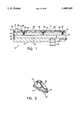
- FIG. 2is a perspective view of the sight used in the barrel assembly shown in FIG. 1.
- FIG. 1there is shown a cross-sectional view of a barrel assembly 10 incorporating features of the present invention.
- the present inventionwill be described with reference to the single embodiment shown in the drawings, it should be understood that the present invention may be incorporated into various different alternate embodiments and various different types of firearms.
- any suitable size, shape or type of elements or materialcould be used.
- the barrel assembly 10generally comprises a barrel 12, a barrel rib 14, and a front sight 16.
- the barrel 12is comprised of metal.
- the barrel assemblyis for use in a semi-automatic pistol and has a rifled bore 18 and a cartridge chamber 20.
- the barrel assemblycould be in a revolver or other firearm.
- the barrel assembly 10is removable from the rest of the firearm.
- the barrel assemblyneed not be removable.
- Located at the bottom and rear of the barrel 12is a block 22 fixedly attached to the barrel.
- the block 22is used to position the barrel on the frame of the pistol, such as disclosed in U.S. Pat. No. 4,109,403, which is hereby incorporated by reference in its entirety.
- the top side of the barrel 12has threaded screw holes 24.
- the screw holesreceive screws 26.
- the screws 26are used to fixedly, stationarily and removably mount the barrel rib 14 to the barrel 12.
- any suitable meanscould be used to mount the barrel rib 14 to the barrel 12, including non-removable means.
- the barrel rib 14is preferably made of metal.
- the rib 14is mounted to the top side of barrel 12 by the screws 26.
- the rib 14includes channels 28, screw holes 30, and a front sight mounting aperture 32.
- the channels 28are provided for transfering heat from the barrel 12 to the air.
- the mounting aperture 32extends through the rib from a top surface of the rib 14 to a bottom surface of the rib 14.
- the bottom surface of the rib 14is contoured to seatingly mate with the top surface of the barrel 12.
- the sight aperture 32in the embodiment shown, has a first lower section 34 and a second upper section 36.
- the upper section 36is smaller than the lower section 34. This size difference is used to interlock with the front sight 16.
- any suitable type of interlock between the sight 16 and the rib 14could be provided.
- the sight 16is preferably comprised of metal with a top section 38 and a bottom section 40.
- the bottom section 40is larger in width and length than the top section 38.
- the bottom section 40forms a peripheral rim or pedestal-type base about the base of the top section.
- the bottom section 40is matingly located in the lower section 34 of the mounting aperture 32.
- the top section 38extends through the upper section 36 of the aperture 32 and up past the top surface of the barrel rib 14.
- the bottom surface 42 of the front sight 16is located against the top surface of the barrel 12.
- the top surface 44 of the bottom section 40 of the sight 16is contacted by the ledge 46 of the barrel rib 14.
- the present inventionallows a user to replace the front sight 16 with another sight.
- the bottom section 40 of the front sight 16is merely entrapped between the ledge 46 and the top surface of the barrel 12.
- the sight 16is not fastened to the barrel 12 or barrel rib 14 by any other means.
- the interlocking nature of the members 12, 14, 16, 26provides the sole means for connecting the front sight 16 to the barrel 12. Because the barrel rib 14 can be removed from the barrel 12 by removing the screws 26 and, because the sight 16 is merely trapped between the barrel and the barrel rib, the sight 16 can be replaced when the barrel rib 14 is removed from the barrel 12.
- the present inventioncould be used with an adjustable sight assembly with a stationary entrapped portion.
- This same type of entrapment sight mountingcould also be used with a rear sight of a firearm.
- Other shapes for interlocking the sight with the barrel rib at the sight mounting aperturecould also be used, such as a tapered aperture and/or sight.
- the front of the barrel top surface, under the sightcould have a notch for receiving a bottom projection on the sight. In this fashion, there can be direct registration of the sight at a predetermined position of the barrel rather than merely the indirect registration by the barrel rib 14.
Landscapes
- Physics & Mathematics (AREA)
- Optics & Photonics (AREA)
- Engineering & Computer Science (AREA)
- General Engineering & Computer Science (AREA)
- Surgical Instruments (AREA)
Abstract
Description
Claims (13)
Priority Applications (1)
| Application Number | Priority Date | Filing Date | Title |
|---|---|---|---|
| US08/309,765US5443543A (en) | 1994-09-21 | 1994-09-21 | Firearm barrel assembly with removable sight |
Applications Claiming Priority (1)
| Application Number | Priority Date | Filing Date | Title |
|---|---|---|---|
| US08/309,765US5443543A (en) | 1994-09-21 | 1994-09-21 | Firearm barrel assembly with removable sight |
Publications (1)
| Publication Number | Publication Date |
|---|---|
| US5443543Atrue US5443543A (en) | 1995-08-22 |
Family
ID=23199600
Family Applications (1)
| Application Number | Title | Priority Date | Filing Date |
|---|---|---|---|
| US08/309,765Expired - Fee RelatedUS5443543A (en) | 1994-09-21 | 1994-09-21 | Firearm barrel assembly with removable sight |
Country Status (1)
| Country | Link |
|---|---|
| US (1) | US5443543A (en) |
Cited By (10)
| Publication number | Priority date | Publication date | Assignee | Title |
|---|---|---|---|---|
| RU2118779C1 (en)* | 1997-04-22 | 1998-09-10 | Открытое акционерное общество "Тульский оружейный завод" | Method of connection of ventilated sighting bar to gun barrel |
| US5836100A (en)* | 1996-07-10 | 1998-11-17 | Williams Gun Sight Co. | Fiber optic sight |
| EP1553380A1 (en)* | 2004-01-09 | 2005-07-13 | Philippe Morales | Adjustable sigting rib |
| US20090113780A1 (en)* | 2007-01-08 | 2009-05-07 | Jere F. Irwin | Shotgun sight and adjustable gun sight |
| US7862535B2 (en) | 2004-05-25 | 2011-01-04 | Covidien Ag | Re-certification system for a flow control apparatus |
| US8034028B2 (en) | 2004-05-25 | 2011-10-11 | Covidien Ag | Administration feeding set |
| US8684737B1 (en)* | 2011-04-01 | 2014-04-01 | Derrick A Jordan | Handgun trigger training device and method |
| US9335118B1 (en) | 2014-01-08 | 2016-05-10 | Jason Stewart Jackson | Fiber optic weapon sight |
| US9587910B1 (en) | 2014-01-08 | 2017-03-07 | Jason Stewart Jackson | Fiber optic weapon sight |
| US20190186869A1 (en)* | 2017-12-20 | 2019-06-20 | Strike Industries, Inc. | Firearm Front Sight |
Citations (11)
| Publication number | Priority date | Publication date | Assignee | Title |
|---|---|---|---|---|
| US1223476A (en)* | 1916-06-13 | 1917-04-24 | Rudolph Coller | Sight. |
| US1523319A (en)* | 1923-04-06 | 1925-01-13 | Vosmek Ulrich | Rear sight for rifles |
| US2645017A (en)* | 1949-02-21 | 1953-07-14 | Laurence Bono | Gun sight |
| US3945142A (en)* | 1974-08-02 | 1976-03-23 | Carl Walther, Sportwaffenfabrik | Mount for a sight on firearms |
| US4000574A (en)* | 1975-08-08 | 1977-01-04 | The Poly-Choke Company, Incorporated | Rib for handgun |
| US4008536A (en)* | 1975-03-10 | 1977-02-22 | Adams Jean M | Detachable gun sight mounts |
| US4109403A (en)* | 1975-09-25 | 1978-08-29 | Browning Arms Company | Detachable barrel for hand guns |
| US4208821A (en)* | 1978-11-24 | 1980-06-24 | Power Custom, Inc. | Variable range sight |
| US4244114A (en)* | 1979-10-17 | 1981-01-13 | Strahan Travis R | Stepped platform ramp sight for firearms |
| US4651432A (en)* | 1985-09-03 | 1987-03-24 | Forjas Taurus S/A | Aiming system adapted for use in competition revolvers enabling varied and broad adjustment |
| US5208407A (en)* | 1991-04-19 | 1993-05-04 | Williams Gunsight & Outfitters | Gun sight mounting system for shotgun |
- 1994
- 1994-09-21USUS08/309,765patent/US5443543A/ennot_activeExpired - Fee Related
Patent Citations (11)
| Publication number | Priority date | Publication date | Assignee | Title |
|---|---|---|---|---|
| US1223476A (en)* | 1916-06-13 | 1917-04-24 | Rudolph Coller | Sight. |
| US1523319A (en)* | 1923-04-06 | 1925-01-13 | Vosmek Ulrich | Rear sight for rifles |
| US2645017A (en)* | 1949-02-21 | 1953-07-14 | Laurence Bono | Gun sight |
| US3945142A (en)* | 1974-08-02 | 1976-03-23 | Carl Walther, Sportwaffenfabrik | Mount for a sight on firearms |
| US4008536A (en)* | 1975-03-10 | 1977-02-22 | Adams Jean M | Detachable gun sight mounts |
| US4000574A (en)* | 1975-08-08 | 1977-01-04 | The Poly-Choke Company, Incorporated | Rib for handgun |
| US4109403A (en)* | 1975-09-25 | 1978-08-29 | Browning Arms Company | Detachable barrel for hand guns |
| US4208821A (en)* | 1978-11-24 | 1980-06-24 | Power Custom, Inc. | Variable range sight |
| US4244114A (en)* | 1979-10-17 | 1981-01-13 | Strahan Travis R | Stepped platform ramp sight for firearms |
| US4651432A (en)* | 1985-09-03 | 1987-03-24 | Forjas Taurus S/A | Aiming system adapted for use in competition revolvers enabling varied and broad adjustment |
| US5208407A (en)* | 1991-04-19 | 1993-05-04 | Williams Gunsight & Outfitters | Gun sight mounting system for shotgun |
Cited By (15)
| Publication number | Priority date | Publication date | Assignee | Title |
|---|---|---|---|---|
| US5836100A (en)* | 1996-07-10 | 1998-11-17 | Williams Gun Sight Co. | Fiber optic sight |
| RU2118779C1 (en)* | 1997-04-22 | 1998-09-10 | Открытое акционерное общество "Тульский оружейный завод" | Method of connection of ventilated sighting bar to gun barrel |
| EP1553380A1 (en)* | 2004-01-09 | 2005-07-13 | Philippe Morales | Adjustable sigting rib |
| US8361024B2 (en) | 2004-05-25 | 2013-01-29 | Covidien Ag | Administration feeding set |
| US7862535B2 (en) | 2004-05-25 | 2011-01-04 | Covidien Ag | Re-certification system for a flow control apparatus |
| US7998109B2 (en) | 2004-05-25 | 2011-08-16 | Covidien Ag | Re-certification system for a flow control apparatus |
| US8034028B2 (en) | 2004-05-25 | 2011-10-11 | Covidien Ag | Administration feeding set |
| US7540108B2 (en)* | 2007-01-08 | 2009-06-02 | Irwin Jere F | Shotgun sight and adjustable gun sight |
| WO2008140830A3 (en)* | 2007-01-08 | 2010-10-14 | Irwin Jere F | Shotgun sight and adjustable gun sight |
| US20090113780A1 (en)* | 2007-01-08 | 2009-05-07 | Jere F. Irwin | Shotgun sight and adjustable gun sight |
| US8684737B1 (en)* | 2011-04-01 | 2014-04-01 | Derrick A Jordan | Handgun trigger training device and method |
| US9335118B1 (en) | 2014-01-08 | 2016-05-10 | Jason Stewart Jackson | Fiber optic weapon sight |
| US9587910B1 (en) | 2014-01-08 | 2017-03-07 | Jason Stewart Jackson | Fiber optic weapon sight |
| US9909838B1 (en) | 2014-01-08 | 2018-03-06 | Jason Stewart Jackson | Fiber optic weapon sight |
| US20190186869A1 (en)* | 2017-12-20 | 2019-06-20 | Strike Industries, Inc. | Firearm Front Sight |
Similar Documents
| Publication | Publication Date | Title |
|---|---|---|
| US5443543A (en) | Firearm barrel assembly with removable sight | |
| US6655069B2 (en) | Accessory mounts for shotguns and other firearms | |
| US6381895B1 (en) | Over barrel gas tube optical sight mount | |
| US6895708B2 (en) | Accessory mounts for firearms | |
| US7305789B2 (en) | Reversible weapon telescope mount | |
| US10619971B2 (en) | Handguard attachment system for a firearm | |
| US5400539A (en) | Selectively adjustable firearm scope mount | |
| US6779288B1 (en) | Accessory mounts for firearms | |
| US3875675A (en) | All weather scope mounting base | |
| US5945626A (en) | Gas operated firearm with clamp on gas block | |
| US5758448A (en) | Laser system mounting device | |
| US5467552A (en) | Gun sight mounting structure | |
| US8156677B2 (en) | Assemblies and firearms incorporating such assemblies | |
| US7610712B2 (en) | Adjustable rear pistol sight | |
| US4008536A (en) | Detachable gun sight mounts | |
| US4779370A (en) | Firearm with removable barrel and telescopic sight | |
| US4418487A (en) | Mounting bracket for gunsight | |
| US20180340752A1 (en) | Adaptive configuration for a firearm | |
| US20100154275A1 (en) | Magazine well extension | |
| US4166333A (en) | Spent shell container | |
| US7240451B2 (en) | Telescope sight mount for a firearm | |
| US5481818A (en) | Gun sight mounting system | |
| US20250003717A1 (en) | Pistol | |
| US7805875B1 (en) | Firearm magazine grip | |
| US9696118B2 (en) | Rear sight block for AK-type rifles |
Legal Events
| Date | Code | Title | Description |
|---|---|---|---|
| AS | Assignment | Owner name:COLT'S MANUFACTURING COMPANY INC., CONNECTICUT Free format text:ASSIGNMENT OF ASSIGNORS INTEREST;ASSIGNORS:EPES, DENNIS O.;LADD, SCOTT A.;REEL/FRAME:007157/0872 Effective date:19940915 | |
| AS | Assignment | Owner name:FIRST NATIONAL BANK OF BOSTON, THE, MASSACHUSETTS Free format text:SECURITY INTEREST;ASSIGNOR:COLT'S MANUFACTURING COMPANY, INC.;REEL/FRAME:007266/0221 Effective date:19940928 | |
| AS | Assignment | Owner name:FIRST NATIONAL BANK OF BOSTON, AS AGENT, THE, MASS Free format text:SECURITY INTEREST;ASSIGNOR:COLT'S MANUFACTURING COMPANY, INC.;REEL/FRAME:008013/0452 Effective date:19960228 | |
| FEPP | Fee payment procedure | Free format text:PAYOR NUMBER ASSIGNED (ORIGINAL EVENT CODE: ASPN); ENTITY STATUS OF PATENT OWNER: LARGE ENTITY | |
| AS | Assignment | Owner name:BANKBOSTON, N.A., AS AGENT, MASSACHUSETTS Free format text:AMENDED AND RESTATED PATENT COLLATERAL ASSIGNMENT AND SECURITY AGREEMENT, DATED AS OF DECEMBER 23, 1998;ASSIGNOR:COLT'S MANUFACTURING COMPANY, INC.;REEL/FRAME:009678/0541 Effective date:19981216 | |
| REMI | Maintenance fee reminder mailed | ||
| LAPS | Lapse for failure to pay maintenance fees | ||
| FP | Lapsed due to failure to pay maintenance fee | Effective date:19990822 | |
| AS | Assignment | Owner name:FLEET NATIONAL BANK, CONNECTICUT Free format text:SECURITY INTEREST;ASSIGNOR:COLT'S MANUFACTURING COMPANY, INC.;REEL/FRAME:012418/0637 Effective date:20011128 | |
| AS | Assignment | Owner name:CONNECTICUT DEVELOPMENT AUTHORITY, CONNECTICUT Free format text:SECURITY INTEREST;ASSIGNOR:COLT MANUFACTURING COMPANY, INC.;REEL/FRAME:012641/0825 Effective date:20011128 | |
| AS | Assignment | Owner name:CONNECTICUT DEVELOPMENT AUTHORITY, CONNECTICUT Free format text:SECURITY AGREEMENT;ASSIGNOR:COLT'S MANUFACTURING COMPANY LLC;REEL/FRAME:014268/0602 Effective date:20030612 | |
| STCH | Information on status: patent discontinuation | Free format text:PATENT EXPIRED DUE TO NONPAYMENT OF MAINTENANCE FEES UNDER 37 CFR 1.362 |