US5443378A - Apparatus for the sandwich method of injection molding - Google Patents
Apparatus for the sandwich method of injection moldingDownload PDFInfo
- Publication number
- US5443378A US5443378AUS08/272,483US27248394AUS5443378AUS 5443378 AUS5443378 AUS 5443378AUS 27248394 AUS27248394 AUS 27248394AUS 5443378 AUS5443378 AUS 5443378A
- Authority
- US
- United States
- Prior art keywords
- injection unit
- unit
- injection
- hot runner
- accumulator
- Prior art date
- Legal status (The legal status is an assumption and is not a legal conclusion. Google has not performed a legal analysis and makes no representation as to the accuracy of the status listed.)
- Expired - Lifetime
Links
Images


Classifications
- B—PERFORMING OPERATIONS; TRANSPORTING
- B29—WORKING OF PLASTICS; WORKING OF SUBSTANCES IN A PLASTIC STATE IN GENERAL
- B29C—SHAPING OR JOINING OF PLASTICS; SHAPING OF MATERIAL IN A PLASTIC STATE, NOT OTHERWISE PROVIDED FOR; AFTER-TREATMENT OF THE SHAPED PRODUCTS, e.g. REPAIRING
- B29C45/00—Injection moulding, i.e. forcing the required volume of moulding material through a nozzle into a closed mould; Apparatus therefor
- B29C45/16—Making multilayered or multicoloured articles
- B29C45/1642—Making multilayered or multicoloured articles having a "sandwich" structure
- B29C45/1645—Injecting skin and core materials from the same injection cylinder, e.g. mono-sandwich moulding
Definitions
- the present inventionrelates to injection molding machines, and more particularly to an injection molding apparatus capable of producing multiple layer plastic articles having a sandwich layer configuration.
- the sandwich method of injection moldingenables the production of plastic articles whose cross-section has a three-layer configuration.
- the outer or "skin" surfaceis one material
- the inner or "core” structureconsists of another material.
- This constructionhas often been used for thick walled components whose cores consist of foamed material, and in applications where an inexpensive material can be used for the core of an article (replacing an expensive material) the requires special properties at the surface. More recently, there has been an increased emphasis on recycling which has prompted many molders to look for ways to use reground material.
- the sandwich method of moldingcan effectively use reground material as the core material since it still has adequate physical properties. This construction takes advantage of the fact that the outer (skin) material is relatively thin, thereby helping reduce the cost of the molded article by minimizing the amount of virgin material.
- the sandwich configurationis achieved when the two materials are conveyed one after the other into the mold cavity.
- the injected meltbegins to solidify immediately when it has made contact with the mold wall so that the melt at the center of the flow advances faster than the melt in the vicinity of the mold wall. Accordingly, material injected later displaces material injected earlier, particularly in the middle of the cross-section of the flow stream, while the melt that contacts the cold mold walls solidifies to form and maintain the surface layer of the part.
- the subsequent melt flowincludes a second material, the sandwich or three-layer configuration is created.
- injection molding apparatusdesigned to produce the sandwich configuration have employed two injection units, controlled to inject the respective component materials into the mold cavity in the desired timed sequence.
- Machines of this typehave disadvantages involving the high initial cost of the required components and associated control capability for close operation monitoring to ensure that the volume flow of material is constant through the nozzle into the cavity when changing from the skin material to the core material.
- the sandwich molding methoddoes not necessarily require that the two melts be injected at different times from separate injection cylinders. It is also possible to layer the melts in a single cylinder and then inject these "stacked" melts into the mold cavity in a single injection stroke.
- This method of sandwich moldinghas the advantage of allowing the injection process to be set in the same way as standard (single material) injection molding.
- the apparatus to perform the single injection methodwould typically comprise a standard injection molding machine having a main injection unit that receives plastic melt from one or more auxiliary plasticizing units.
- the transfer of the skin and core material into the main injection unitis controlled to achieve a total shot of the two stacked materials in the desired proportions.
- the auxiliary plasticizing unitcan be a non-reciprocating screw extruder connected to a main injection unit having a reciprocating screw for injection.
- the auxiliary unitcould be a second reciprocating screw injection unit where the screw operates in the normal manner to transfer material into the main injection unit; or two extruders supplying an injection accumulator.
- An object of the present inventionis to provide an apparatus of simplified and economical construction particularly adapted to production of articles molded by the sandwich method of injection molding.
- the skin materialis transferred from a non-reciprocating screw extruder through a hot runner manifold directly into the nozzle/barrel of the machine's injection unit.
- the hot runner manifoldis connected directly to the barrel of the extruder, forming in essence an extension of the extruder barrel.
- Preparation for injectionbegins by retracting the injection unit away from the mold after the prior injection cycle is completed. Specifically, the unit is retracted sufficiently to allow connection with the hot runner manifold of the extruder.
- the hot runner manifoldis moved together with the extruder into position, ultimately achieving a fluid tight connection with the nozzle of the injection unit.
- the extruderacts to transfer the plasticized skin material through the hot runner and into the barrel of the injection unit, passing through the unit's injection nozzle.
- the injection unitthen disconnects from the hot runner, the hot runner is moved (with the extruder) away from the injection unit, and the injection moves back into position for injection into the mold. Simultaneously with the movement of the components after the skin material has been transferred, the injection unit plasticizes sufficient core material to complete the stacked arrangement of skin and core material necessary for sandwich molding.
- the extruder for the sandwich molding apparatuscan be oriented vertically (at 90° to the injection unit) so that the hot runner is also moved vertically to establish connection with the injection unit.
- the extrudercan be oriented so that it is rotated to a position approximately parallel to the injection with the hot runner manifold appropriately positioned in front of the injection unit when the unit has retracted to initiate material transfer.
- the sandwich molding apparatusincludes an accumulator to supply a final shot of skin material into the mold, as well as provide the pack and hold functions of the injection cycle. More specifically, the accumulator is connected to the extruder by suitable valving so that a quantity of skin material is transferred into the accumulator just after the primary charge of skin material is transferred into the injection unit barrel. As soon as the valving switches to fill the accumulator, the injection unit begins plasticizing the desired quantity of core material.
- the accumulatoris connected by suitable means to the inlet of the mold cavity, so that after the injection unit has filled the mold cavity with the primary charge, the accumulator can transfer a small quantity of skin material to ensure that the core material is fully contained by the skin material, and that the cavity is properly packed.
- the associated valvingalso allows the accumulator to maintain the desired pressure on the material in the mold, while simultaneously enabling the injection unit to receive skin material from the extruder for the next injection cycle.
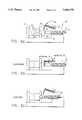
- FIGS. 1a-1cshow a diagrammatic section through an injection molding apparatus in accordance with the present invention having a main injection unit and a vertically oriented auxiliary plasticizing unit.
- FIGS. 2a-2cshow a diagrammatic section through a variation of the apparatus shown in FIG. 1; specifically, the auxiliary plasticizing unit is oriented differently with respect to the injection unit.
- FIG. 3shows a diagrammatic section through an alternate embodiment of the present invention including a main injection unit, an auxiliary plasticizing unit and an accumulator.
- FIGS. 4a-4cshow a diagrammatic section through an accumulator and associated valve that are included in the embodiment of the present invention shown in FIG. 3.
- FIGS. 1a-1cshow a two part mold 10 having a mold cavity 12 for receiving plastic melt from an injection unit 18 to produce a plastic article having a sandwich configuration.
- the two parts of the mold 10are mounted on a stationary platen 4 and a moving platen 6.
- the stationary platen 4, moving platen 8 and injection unit 18are supported by a common base 8.
- the mold constructionincludes a sprue channel 14 which is connected to a nozzle 16 on the injection unit 18 when material is injected into the mold cavity 12.
- the nozzle 16is equipped with a shut-off valve (not shown) of the type that is well-known in the art.
- the main injection unit 18has a barrel 20 which includes a feed screw 22 of a configuration that is typical for injection molding.
- the feed screwis controlled to reciprocate in the barrel 20 to plasticize and inject plastic into the mold 10.
- the injection unit 18is equipped with means, such as a hydraulic cylinder (not shown), to move the unit linearly toward and away from the mold 10. More specifically, the injection unit 18 is moved against the mold 11 for injection, then is retracted away from the mold 10 and stationary platen 4, so that the skin material can be fed into the injection unit barrel 20.
- An auxiliary plasticizing unit 24is mounted adjacent the injection unit 18 on either the. stationary platen 4 or base 8, depending on the desired machine configuration.
- the auxiliary unit 24is a non-reciprocating extruder to provide a more economical apparatus; however, it could also be a second reciprocating screw injection unit, if desired.
- Connected to the end of the auxiliary plasticizing unit 24is a hot runner manifold 26.
- the auxiliary unit 24is mounted on the stationary platen 4 so that it is capable of movement along a line perpendicular to the injection unit 18. This orientation of the auxiliary unit 24 facilitates its positioning so that the hot runner manifold 26 is properly aligned in front of the injection unit 18, enabling direct connection with the nozzle 16.
- FIGS. 1a-1cA cycle of operation will now be described according to the embodiment shown in FIGS. 1a-1c.
- the injection unit 18is retracted to a rearward position (FIG. 1a), that provides clearance between the stationary platen 4 and the nozzle 16.
- the auxiliary unit 24is then moved downward so that the hot runner manifold 26 is disposed in front of the injection unit 18.
- the nozzle 16 of injection unit 18then moves against the hot runner manifold 26 to establish a fluid tight connection between the injection unit 18 and auxiliary unit 24.
- the auxiliary unit 24is then activated to transfer plasticized material via the hot runner manifold 26, through the nozzle 16 and into the end of the barrel 20 of the injection unit 18, causing the screw 22 to move backward within the barrel.
- the transfer of the skin material from the auxiliary unitcontinues until a sufficient volume as defined by the part geometry has been transferred, see FIG. 1b.
- the injection unit 18plasticizes a sufficient quantity of the core material by rotating and retracting the feed screw 22 in a conventional manner so that a full shot of melt is prepared. Simultaneously with the plasticizing function, the injection unit 18 disconnects from the auxiliary unit 24 by retracting slightly. The auxiliary unit 24 moves upward so that the injection unit 18 can now move forward unobstructed to a position where the nozzle 16 communicates with the sprue channel 14 of the mold 10. The injection unit 18 then injects the accumulated shot of core and skin material into the mold 10 by advancing the feed screw 22 in a manner typical of the injection molding process.
- FIGS. 2a-2cThe apparatus of the preferred embodiment shown in an alternate configuration in FIGS. 2a-2c that is only slightly different from the structure shown in FIGS. 1a-1c.
- the auxiliary unit 24is mounted in a manner that allows it to be parallel with the main injection unit 18 during the material transfer function.
- the auxiliary unit 24 and hot runner manifold 26pivot or rotate from a position connecting the auxiliary unit 24 and the main injection unit 18 to a position that is sufficiently clear of the main injection unit 18 when it moves back and forth with respect to the stationary platen 4.
- FIG. 2a-2cthe operation of the alternate apparatus of FIG. 2a-2c is very similar to that shown in FIG. 1a-1c.
- the primary differenceis the way that the auxiliary unit 24 and hot runner manifold 24 move in and out of position with respect to the main injection unit 18 to allow transfer of the skin material. More specifically, when the injection unit is retracted away from the mold (FIG. 2a), the auxiliary unit 24 and hot runner manifold 26 rotate into position so that the nozzle 16 of the main injection unit 18 is connected to the hot runner manifold 26 (FIG. 2b). This connection then allows transfer of the skin material from the auxiliary unit 24 through the hot runner 26 into the barrel 20 of the injection unit 18.
- the hot runner 26 and auxiliary unit 24are rotated to the clearance position and the main injection unit plasticizes the desired quantity of the core material as it moves into position against the mold (FIG. 2c). Once the full charge of melt has been accumulated, the injection unit 18 is ready to inject the stacked plastic melt into the mold cavity 12, forming the desired sandwich configuration for the molded article.
- the injection cycleincludes time to fill and pack the mold cavity 12. Once the material in the sprue channel 14 has sufficiently hardened, the injection unit 18 retracts so that the hot runner manifold 26 can be connected as described earlier to allow for transfer of the skin material into the injection unit 18, and begin building a shot of material for the next cycle.
- various parts of the operation cycleoverlap to minimize total cycle time. For example, after the skin material has transferred from the auxiliary unit 24 into the injection unit 18, the plasticizing of the core material would be simultaneous with the retraction of the hot runner 26 and subsequent movement of the injection unit 18 towards the mold 10. It is anticipated that in most cases, the necessary functions will overlap sufficiently so that "dead time" within the cycle is avoided or, at least, minimal.
- FIGS. 3 and 4a-4cThe apparatus used in an alternate embodiment of the present invention is shown in FIGS. 3 and 4a-4c.
- the primary feature of this embodimentis the addition of an accumulator 28 and a flow control valve 30.
- the valve 30in conjunction with suitable conduits enables connection of the accumulator 28 with the auxiliary plasticizing unit 24 and the mold cavity 12 via the sprue channel 14.
- the accumulator 28functions to supply a final shot of skin material into the mold 10 after injection of the stacked materials by the main injection unit 18.
- the accumulator 28can be used to provide the pack and hold functions at the end of the injection cycle, allowing more flexibility in sequencing the elements of the injection cycle.
- skin materialis transferred into the accumulator 28 by the auxiliary unit 24 after the desired charge of skin material has been transferred into the injection unit 18. More specifically, upon completion of material transfer into the injection unit 18, the valve 30 is actuated to establish material flow from the auxiliary unit 24 to the accumulator 28. As soon as transfer of the skin material has been diverted to the accumulator 28, the injection unit 18 can begin plasticizing the desired quantity of core material.
- the material transfer into accumulator 28could occur simultaneously with the transfer into the injection unit 18, or, with suitable valving, transfer could be delayed so that skin material is fed into the accumulator 28 by the injection unit 18 simultaneously with injection into the mold. In the latter case, it is important to control the rate of flow into the accumulator 28 in order to maintain the desired injection pressure profile at the mold.
- the accumulator 28is also connected to the mold cavity 12. After the injection unit 18 has injected the primary charge of skin and core material to fill the mold cavity 10, valve 30 is actuated to establish the necessary connection, and the accumulator 28 is operated to pack the mold cavity 10 with a small charge of skin material. This final injection by the accumulator 28 not only makes sure the mold cavity 12 contains a fully formed article, but also ensures that the core material is fully contained or covered by the skin material.
- the accumulator 28 functioncontinues after the injection by maintaining the mold pressure while the molded article cools. Since the pressure is held by the accumulator 28, the injection unit 18 is free to begin receiving skin material from the auxiliary unit in preparation for the next operating cycle.
Landscapes
- Engineering & Computer Science (AREA)
- Manufacturing & Machinery (AREA)
- Mechanical Engineering (AREA)
- Injection Moulding Of Plastics Or The Like (AREA)
- Moulds For Moulding Plastics Or The Like (AREA)
Abstract
Description
Claims (5)
Priority Applications (7)
| Application Number | Priority Date | Filing Date | Title |
|---|---|---|---|
| US08/272,483US5443378A (en) | 1994-07-11 | 1994-07-11 | Apparatus for the sandwich method of injection molding |
| DE59509524TDE59509524D1 (en) | 1994-07-11 | 1995-06-07 | Injection molding device |
| AT95108706TATE184233T1 (en) | 1994-07-11 | 1995-06-07 | DEVICE FOR INJECTION MOLDING USING THE SANDWICH METHOD |
| EP95108706AEP0692359B1 (en) | 1994-07-11 | 1995-06-07 | Apparatus for sandwich injection moulding |
| EP99104452AEP0920968B1 (en) | 1994-07-11 | 1995-06-07 | Apparatus for injection moulding |
| DE59506768TDE59506768D1 (en) | 1994-07-11 | 1995-06-07 | Device for injection molding in the sandwich process |
| AT99104452TATE204225T1 (en) | 1994-07-11 | 1995-06-07 | DEVICE FOR INJECTION MOLDING |
Applications Claiming Priority (1)
| Application Number | Priority Date | Filing Date | Title |
|---|---|---|---|
| US08/272,483US5443378A (en) | 1994-07-11 | 1994-07-11 | Apparatus for the sandwich method of injection molding |
Publications (1)
| Publication Number | Publication Date |
|---|---|
| US5443378Atrue US5443378A (en) | 1995-08-22 |
Family
ID=23039989
Family Applications (1)
| Application Number | Title | Priority Date | Filing Date |
|---|---|---|---|
| US08/272,483Expired - LifetimeUS5443378A (en) | 1994-07-11 | 1994-07-11 | Apparatus for the sandwich method of injection molding |
Country Status (4)
| Country | Link |
|---|---|
| US (1) | US5443378A (en) |
| EP (2) | EP0692359B1 (en) |
| AT (2) | ATE184233T1 (en) |
| DE (2) | DE59509524D1 (en) |
Cited By (40)
| Publication number | Priority date | Publication date | Assignee | Title |
|---|---|---|---|---|
| WO1998023433A1 (en)* | 1996-11-28 | 1998-06-04 | Rafael Zvi Karl Kilim | Moulding plastics article by varying cyclically its composition |
| US5798069A (en)* | 1994-06-06 | 1998-08-25 | Husky Injection Molding Systems Ltd. | Opposed gating injection method |
| EP0897784A1 (en)* | 1997-08-20 | 1999-02-24 | Orga Kartensysteme GmbH | Chip card, method for producing chip cards as well as apparatus for carrying out the method |
| WO1999010158A1 (en)* | 1997-08-21 | 1999-03-04 | Structoform Spritzgiessen Anisotroper Strukturkomponenten Gmbh | Method for injection moulding, injection mould, injection moulding device and method for filling a main extruder from a secondary extruder |
| US6312641B1 (en) | 1997-10-17 | 2001-11-06 | Plastic Fabrication Technologies Llc | Method of making containers and preforms incorporating barrier materials |
| US6352426B1 (en) | 1998-03-19 | 2002-03-05 | Advanced Plastics Technologies, Ltd. | Mold for injection molding multilayer preforms |
| US6352427B1 (en)* | 2000-04-06 | 2002-03-05 | Mgs Mfg. Group, Inc. | Multi-shot injection molding arrangement |
| WO2002020242A1 (en)* | 2000-09-05 | 2002-03-14 | Community Enterprises, Llc | Apparatus for molding multilayered articles |
| US6370986B1 (en) | 1999-03-25 | 2002-04-16 | The Stanley Works | Impact cushioning tool handle |
| US6391408B1 (en) | 1997-10-17 | 2002-05-21 | Advanced Plastics Technologies, Ltd. | Coated polyester preforms and method of making same |
| US20020079603A1 (en)* | 2000-11-30 | 2002-06-27 | Bemis Manufacturing Company | Co-injection methods using endothermic-blowing agents and products made therefrom |
| US6419869B1 (en)* | 1996-05-22 | 2002-07-16 | Eldra Kunststofftechnik Gmbh | Method of producing high-grade plastic parts and an injection-moulded part |
| US20020102320A1 (en)* | 2000-04-06 | 2002-08-01 | Hahn John J. | Multi-shot injection molding arrangement |
| EP1264785A1 (en)* | 2001-05-29 | 2002-12-11 | Habasit AG | Modular conveyor belt |
| WO2003033235A1 (en) | 2001-10-18 | 2003-04-24 | Community Enterprises, Llc | Apparatus for injection molding multilayered articles |
| US6627134B2 (en) | 2000-09-05 | 2003-09-30 | Community Enterprises, Llc | Apparatus for molding multilayered articles |
| US20030209833A1 (en)* | 2000-02-29 | 2003-11-13 | Bemis Peter F. | Co-injection apparatus for injection molding |
| WO2004007319A1 (en)* | 2002-07-12 | 2004-01-22 | Habasit Ag | Modular conveyor belting with antimicrobial characteristics |
| US20040022975A1 (en)* | 2000-10-19 | 2004-02-05 | Hodaka Yokomizo | Multi-layer preliminary formed body and method of manufacturing the formed body |
| US6689303B2 (en)* | 2001-10-15 | 2004-02-10 | Yamatake Corporation | Injection molding method using a stacked mold |
| US6696003B2 (en) | 2001-05-29 | 2004-02-24 | Habasit Ag | Methods for manufacturing a module for a modular conveyor belt having a sandwich layer construction |
| US6716387B2 (en) | 2001-02-28 | 2004-04-06 | Alliance Systems, Inc. | Process for pressure assisted molding of hollow articles |
| US20040073335A1 (en)* | 2002-10-10 | 2004-04-15 | Shao-Wei Gong | Ultra-precision robotic system |
| US20040130066A1 (en)* | 2002-11-19 | 2004-07-08 | Atsushi Koide | Method for controlling thickness of skin layer of composite resin molded product |
| US20040175454A1 (en)* | 2003-01-27 | 2004-09-09 | Joel Thomson | Devices and methods for maximizing purge effectiveness for molding machines |
| US6808820B2 (en) | 2000-09-05 | 2004-10-26 | Advanced Plastics Technology Ltd. | Multilayer containers and preforms having barrier properties utilizing recycled material |
| US20050015990A1 (en)* | 2003-07-25 | 2005-01-27 | Barone Chris A. | Method for producing a shaving aid cartridge |
| US6880696B2 (en) | 2001-05-29 | 2005-04-19 | Habasit Ag | Module for a modular conveyor belt having a sandwich layer construction and method of manufacture |
| US20060159793A1 (en)* | 2000-04-06 | 2006-07-20 | Hahn John J | Multi-shot injection molding arrangement |
| US20070243284A1 (en)* | 2006-04-12 | 2007-10-18 | Georg Steinbichler | Device for Expansion Injection Moulding |
| US7303387B2 (en) | 2004-06-10 | 2007-12-04 | Advanced Plastics Technologies Luxembourg S.A. | System for controlling mold temperatures |
| US20080063869A1 (en)* | 2006-08-23 | 2008-03-13 | Husky Injection Molding Systems Ltd. | Compounding molding system, amongst other things |
| US7367795B2 (en) | 2002-11-08 | 2008-05-06 | Advanced Plastics Technologies Luxembourg S.A. | Injection mold having a wear resistant portion and a high heat transfer portion |
| US7588808B2 (en) | 2004-04-16 | 2009-09-15 | Advanced Plastics Technologies Luxembourg S.A. | Mono and multi-layer articles and injection molding methods of making the same |
| US7717697B2 (en) | 2005-08-30 | 2010-05-18 | Sharon Hutchinson | Methods and systems for controlling mold temperatures |
| US9248593B2 (en) | 2012-10-15 | 2016-02-02 | Mold-Masters (2007) Limited | Injection unit positioning apparatus |
| US10675799B2 (en) | 2015-11-06 | 2020-06-09 | Mold-Masters (2007) Limited | Injection unit positioning apparatus |
| CN112810077A (en)* | 2020-12-30 | 2021-05-18 | 东风汽车集团有限公司 | Auxiliary runner structure for preventing injection molding product from deforming |
| CN112936723A (en)* | 2021-03-02 | 2021-06-11 | 广东伊之密精密注压科技有限公司 | A kind of sandwich injection molding equipment and method |
| US12179398B2 (en) | 2020-06-25 | 2024-12-31 | Engel Austria Gmbh | Injection unit for a moulding machine and method for injecting a plasticized mass |
Families Citing this family (4)
| Publication number | Priority date | Publication date | Assignee | Title |
|---|---|---|---|---|
| JP4201481B2 (en) | 2000-12-25 | 2008-12-24 | 株式会社神戸製鋼所 | Molded product, injection molding method thereof, and injection molding apparatus thereof |
| DE102009007049A1 (en) | 2009-01-27 | 2010-08-12 | Neo-Plastic Dr. Doetsch Diespeck Gmbh | Bearing unit e.g. rotary bearing, for e.g. door, has seal produced in sandwich injection molding process such that core is completely closed by coating, where seal cooperating with core is fixed at guide rail or carriage or ring devices |
| AT521056B1 (en)* | 2018-06-27 | 2019-10-15 | Engel Austria Gmbh | Two-component plasticizing |
| DE102020101748A1 (en) | 2019-12-23 | 2021-06-24 | Ferromatik Milacron Gmbh | Multi-component injection molding machine |
Citations (10)
| Publication number | Priority date | Publication date | Assignee | Title |
|---|---|---|---|---|
| US3888612A (en)* | 1971-01-28 | 1975-06-10 | Ici Ltd | Injection moulding means for forming a composite product |
| US4090836A (en)* | 1976-04-06 | 1978-05-23 | Fried. Krupp Gesellschaft Mit Beschrankter Haftung | Injection die casting apparatus, especially for making molded parts of thermoplast-structural foam |
| US4715802A (en)* | 1985-06-27 | 1987-12-29 | Canon Kabushiki Kaisha | Injection molding machine |
| US4722679A (en)* | 1986-06-13 | 1988-02-02 | Tri-Delta Technology, Inc. | Injection molding machine |
| US4978493A (en)* | 1986-07-21 | 1990-12-18 | Stamicarbon B.V. | Process for injection moulding multilayered articles |
| EP0419911A2 (en)* | 1989-09-28 | 1991-04-03 | Ferromatik Milacron Maschinenbau GmbH | Method and apparatus for injection moulding multi-component plastic bodies |
| US5034177A (en)* | 1988-12-20 | 1991-07-23 | Mitsui Petrochemical Industries, Ltd. | Method for molding saturated crystalline polyesters |
| US5215762A (en)* | 1990-07-16 | 1993-06-01 | Kloeckner-Ferromatik Desma Gmbh | Nozzle for injection molding machine |
| US5286184A (en)* | 1991-04-15 | 1994-02-15 | The Japan Steel Works, Ltd. | Injection molding apparatus having two hot runner blocks for producing a composite article |
| US5366366A (en)* | 1992-07-01 | 1994-11-22 | Sodick Co., Ltd. | Injection molding machine having a machine screw driving gear |
Family Cites Families (2)
| Publication number | Priority date | Publication date | Assignee | Title |
|---|---|---|---|---|
| GB1420948A (en)* | 1972-10-26 | 1976-01-14 | Ici Ltd | Injection moulding process |
| DE3712325A1 (en)* | 1987-04-11 | 1988-10-27 | Steinl Landshuter Werkzeug | INJECTION MOLDING DEVICE |
- 1994
- 1994-07-11USUS08/272,483patent/US5443378A/ennot_activeExpired - Lifetime
- 1995
- 1995-06-07DEDE59509524Tpatent/DE59509524D1/ennot_activeExpired - Fee Related
- 1995-06-07EPEP95108706Apatent/EP0692359B1/ennot_activeExpired - Lifetime
- 1995-06-07ATAT95108706Tpatent/ATE184233T1/ennot_activeIP Right Cessation
- 1995-06-07ATAT99104452Tpatent/ATE204225T1/ennot_activeIP Right Cessation
- 1995-06-07EPEP99104452Apatent/EP0920968B1/ennot_activeExpired - Lifetime
- 1995-06-07DEDE59506768Tpatent/DE59506768D1/ennot_activeExpired - Fee Related
Patent Citations (10)
| Publication number | Priority date | Publication date | Assignee | Title |
|---|---|---|---|---|
| US3888612A (en)* | 1971-01-28 | 1975-06-10 | Ici Ltd | Injection moulding means for forming a composite product |
| US4090836A (en)* | 1976-04-06 | 1978-05-23 | Fried. Krupp Gesellschaft Mit Beschrankter Haftung | Injection die casting apparatus, especially for making molded parts of thermoplast-structural foam |
| US4715802A (en)* | 1985-06-27 | 1987-12-29 | Canon Kabushiki Kaisha | Injection molding machine |
| US4722679A (en)* | 1986-06-13 | 1988-02-02 | Tri-Delta Technology, Inc. | Injection molding machine |
| US4978493A (en)* | 1986-07-21 | 1990-12-18 | Stamicarbon B.V. | Process for injection moulding multilayered articles |
| US5034177A (en)* | 1988-12-20 | 1991-07-23 | Mitsui Petrochemical Industries, Ltd. | Method for molding saturated crystalline polyesters |
| EP0419911A2 (en)* | 1989-09-28 | 1991-04-03 | Ferromatik Milacron Maschinenbau GmbH | Method and apparatus for injection moulding multi-component plastic bodies |
| US5215762A (en)* | 1990-07-16 | 1993-06-01 | Kloeckner-Ferromatik Desma Gmbh | Nozzle for injection molding machine |
| US5286184A (en)* | 1991-04-15 | 1994-02-15 | The Japan Steel Works, Ltd. | Injection molding apparatus having two hot runner blocks for producing a composite article |
| US5366366A (en)* | 1992-07-01 | 1994-11-22 | Sodick Co., Ltd. | Injection molding machine having a machine screw driving gear |
Non-Patent Citations (2)
| Title |
|---|
| Jaroschek, "New Ways With the Sandwich Method of Injection Molding", Kunststoffe/German Plastics, vol. 83, Jul. 1993. |
| Jaroschek, New Ways With the Sandwich Method of Injection Molding , Kunststoffe/German Plastics, vol. 83, Jul. 1993.* |
Cited By (62)
| Publication number | Priority date | Publication date | Assignee | Title |
|---|---|---|---|---|
| US5798069A (en)* | 1994-06-06 | 1998-08-25 | Husky Injection Molding Systems Ltd. | Opposed gating injection method |
| US6419869B1 (en)* | 1996-05-22 | 2002-07-16 | Eldra Kunststofftechnik Gmbh | Method of producing high-grade plastic parts and an injection-moulded part |
| CN1080636C (en)* | 1996-11-28 | 2002-03-13 | 拉斐尔·兹维·卡尔·基利姆 | molded plastic products |
| WO1998023433A1 (en)* | 1996-11-28 | 1998-06-04 | Rafael Zvi Karl Kilim | Moulding plastics article by varying cyclically its composition |
| US6287491B1 (en)* | 1996-11-28 | 2001-09-11 | Rafael Zvi Karl Kilim | Moulding plastics article by varying cyclically its composition |
| EP0897784A1 (en)* | 1997-08-20 | 1999-02-24 | Orga Kartensysteme GmbH | Chip card, method for producing chip cards as well as apparatus for carrying out the method |
| WO1999010158A1 (en)* | 1997-08-21 | 1999-03-04 | Structoform Spritzgiessen Anisotroper Strukturkomponenten Gmbh | Method for injection moulding, injection mould, injection moulding device and method for filling a main extruder from a secondary extruder |
| US7645135B2 (en) | 1997-10-17 | 2010-01-12 | Advanced Plastics Technologies Luxembourg S.A. | Mold for injecting molding preforms |
| US7261551B2 (en) | 1997-10-17 | 2007-08-28 | Advanced Plastics Technologies Luxembourg S.A. | Preform molds incorporating high heat conductivity material |
| US6939591B2 (en) | 1997-10-17 | 2005-09-06 | Advanced Plastics Technologies, Ltd. | Polyester laminate materials |
| US6676883B2 (en) | 1997-10-17 | 2004-01-13 | Advanced Plastics Technologies | Methods for preparing coated polyester articles |
| US6391408B1 (en) | 1997-10-17 | 2002-05-21 | Advanced Plastics Technologies, Ltd. | Coated polyester preforms and method of making same |
| US6312641B1 (en) | 1997-10-17 | 2001-11-06 | Plastic Fabrication Technologies Llc | Method of making containers and preforms incorporating barrier materials |
| US20030219555A1 (en)* | 1997-10-17 | 2003-11-27 | Hutchinson Gerald A. | Coated polyester preforms and articles |
| US7332204B2 (en) | 1997-10-17 | 2008-02-19 | Advanced Plastics Technologies Luxembourg S.A. | Coated polyester preforms and articles |
| US6352426B1 (en) | 1998-03-19 | 2002-03-05 | Advanced Plastics Technologies, Ltd. | Mold for injection molding multilayer preforms |
| US6370986B1 (en) | 1999-03-25 | 2002-04-16 | The Stanley Works | Impact cushioning tool handle |
| US7531226B2 (en) | 1999-04-21 | 2009-05-12 | Advanced Plastics Technologies Luxembourg S.A. | Multilayer containers and preforms having barrier properties utilizing recycled material |
| US20050053739A1 (en)* | 1999-04-21 | 2005-03-10 | Lee Robert A. | Multilayer containers and preforms having barrier properties utilizing recycled material |
| US20030209833A1 (en)* | 2000-02-29 | 2003-11-13 | Bemis Peter F. | Co-injection apparatus for injection molding |
| US6974556B2 (en) | 2000-02-29 | 2005-12-13 | Bemis Manufacturing Company | Co-injection apparatus for injection molding |
| US6352427B1 (en)* | 2000-04-06 | 2002-03-05 | Mgs Mfg. Group, Inc. | Multi-shot injection molding arrangement |
| US7393199B2 (en) | 2000-04-06 | 2008-07-01 | Mgs Mfg. Group, Inc. | Multi-shot injection molding arrangement |
| US20060159793A1 (en)* | 2000-04-06 | 2006-07-20 | Hahn John J | Multi-shot injection molding arrangement |
| US6994810B2 (en) | 2000-04-06 | 2006-02-07 | Mgs Mfg. Group, Inc. | Multi-shot injection molding arrangement |
| US20020102320A1 (en)* | 2000-04-06 | 2002-08-01 | Hahn John J. | Multi-shot injection molding arrangement |
| US6627134B2 (en) | 2000-09-05 | 2003-09-30 | Community Enterprises, Llc | Apparatus for molding multilayered articles |
| WO2002020242A1 (en)* | 2000-09-05 | 2002-03-14 | Community Enterprises, Llc | Apparatus for molding multilayered articles |
| US6808820B2 (en) | 2000-09-05 | 2004-10-26 | Advanced Plastics Technology Ltd. | Multilayer containers and preforms having barrier properties utilizing recycled material |
| US7344673B2 (en)* | 2000-10-19 | 2008-03-18 | Teijin Limited | Multi-layer preliminary formed body and method of manufacturing the formed body |
| US20040022975A1 (en)* | 2000-10-19 | 2004-02-05 | Hodaka Yokomizo | Multi-layer preliminary formed body and method of manufacturing the formed body |
| US20020079603A1 (en)* | 2000-11-30 | 2002-06-27 | Bemis Manufacturing Company | Co-injection methods using endothermic-blowing agents and products made therefrom |
| US6964748B2 (en) | 2000-11-30 | 2005-11-15 | Bemis Manufacturing Company | Co-injection methods using endothermic-blowing agents and products made therefrom |
| US6716387B2 (en) | 2001-02-28 | 2004-04-06 | Alliance Systems, Inc. | Process for pressure assisted molding of hollow articles |
| US6880696B2 (en) | 2001-05-29 | 2005-04-19 | Habasit Ag | Module for a modular conveyor belt having a sandwich layer construction and method of manufacture |
| EP1264785A1 (en)* | 2001-05-29 | 2002-12-11 | Habasit AG | Modular conveyor belt |
| US6696003B2 (en) | 2001-05-29 | 2004-02-24 | Habasit Ag | Methods for manufacturing a module for a modular conveyor belt having a sandwich layer construction |
| US6689303B2 (en)* | 2001-10-15 | 2004-02-10 | Yamatake Corporation | Injection molding method using a stacked mold |
| WO2003033235A1 (en) | 2001-10-18 | 2003-04-24 | Community Enterprises, Llc | Apparatus for injection molding multilayered articles |
| WO2004007319A1 (en)* | 2002-07-12 | 2004-01-22 | Habasit Ag | Modular conveyor belting with antimicrobial characteristics |
| US20040073335A1 (en)* | 2002-10-10 | 2004-04-15 | Shao-Wei Gong | Ultra-precision robotic system |
| US7367795B2 (en) | 2002-11-08 | 2008-05-06 | Advanced Plastics Technologies Luxembourg S.A. | Injection mold having a wear resistant portion and a high heat transfer portion |
| US7294302B2 (en)* | 2002-11-19 | 2007-11-13 | Nissei Plastic Industrial Co., Ltd. | Method for controlling thickness of skin layer of composite resin molded product |
| US20040130066A1 (en)* | 2002-11-19 | 2004-07-08 | Atsushi Koide | Method for controlling thickness of skin layer of composite resin molded product |
| US20040175454A1 (en)* | 2003-01-27 | 2004-09-09 | Joel Thomson | Devices and methods for maximizing purge effectiveness for molding machines |
| US20050015990A1 (en)* | 2003-07-25 | 2005-01-27 | Barone Chris A. | Method for producing a shaving aid cartridge |
| US7588808B2 (en) | 2004-04-16 | 2009-09-15 | Advanced Plastics Technologies Luxembourg S.A. | Mono and multi-layer articles and injection molding methods of making the same |
| US8551589B2 (en) | 2004-04-16 | 2013-10-08 | The Concentrate Manufacturing Company Of Ireland | Mono and multi-layer articles and extrusion methods of making the same |
| US7303387B2 (en) | 2004-06-10 | 2007-12-04 | Advanced Plastics Technologies Luxembourg S.A. | System for controlling mold temperatures |
| US7578668B2 (en) | 2004-06-10 | 2009-08-25 | Advanced Plastics Technologies Luxembourg S.A. | Mold assembly having a pressure reducing device |
| US7717697B2 (en) | 2005-08-30 | 2010-05-18 | Sharon Hutchinson | Methods and systems for controlling mold temperatures |
| US20070243284A1 (en)* | 2006-04-12 | 2007-10-18 | Georg Steinbichler | Device for Expansion Injection Moulding |
| US20080063869A1 (en)* | 2006-08-23 | 2008-03-13 | Husky Injection Molding Systems Ltd. | Compounding molding system, amongst other things |
| US20110165424A1 (en)* | 2006-08-23 | 2011-07-07 | Husky Injection Molding Systems Ltd. | Compounding molding method, amongst other things |
| US9248593B2 (en) | 2012-10-15 | 2016-02-02 | Mold-Masters (2007) Limited | Injection unit positioning apparatus |
| US10675799B2 (en) | 2015-11-06 | 2020-06-09 | Mold-Masters (2007) Limited | Injection unit positioning apparatus |
| US11534947B2 (en) | 2015-11-06 | 2022-12-27 | Mold-Masters (2007) Limited | Injection unit positioning apparatus |
| US12179398B2 (en) | 2020-06-25 | 2024-12-31 | Engel Austria Gmbh | Injection unit for a moulding machine and method for injecting a plasticized mass |
| CN112810077A (en)* | 2020-12-30 | 2021-05-18 | 东风汽车集团有限公司 | Auxiliary runner structure for preventing injection molding product from deforming |
| CN112810077B (en)* | 2020-12-30 | 2022-02-08 | 东风汽车集团有限公司 | Auxiliary runner structure for preventing injection molding product from deforming |
| CN112936723A (en)* | 2021-03-02 | 2021-06-11 | 广东伊之密精密注压科技有限公司 | A kind of sandwich injection molding equipment and method |
| CN112936723B (en)* | 2021-03-02 | 2025-08-05 | 广东伊之密精密注压科技有限公司 | Sandwich injection molding equipment and method |
Also Published As
| Publication number | Publication date |
|---|---|
| EP0920968A3 (en) | 1999-12-08 |
| EP0692359B1 (en) | 1999-09-08 |
| ATE204225T1 (en) | 2001-09-15 |
| EP0920968B1 (en) | 2001-08-16 |
| EP0920968A2 (en) | 1999-06-09 |
| EP0692359A1 (en) | 1996-01-17 |
| ATE184233T1 (en) | 1999-09-15 |
| DE59506768D1 (en) | 1999-10-14 |
| DE59509524D1 (en) | 2001-09-20 |
Similar Documents
| Publication | Publication Date | Title |
|---|---|---|
| US5443378A (en) | Apparatus for the sandwich method of injection molding | |
| CA1110814A (en) | Sequential co-injection unit adapted for structural foam molding | |
| US5454995A (en) | Method for reducing cycle time in an injection molding machine | |
| US6953546B2 (en) | Plastic expulsion process for forming hollow tubular products | |
| JPS6225027A (en) | Injection molding device | |
| EP2569137B1 (en) | Mold assembly with integrated melting devices | |
| EP1066945B1 (en) | Method for controlling an injection molding machine | |
| US4005167A (en) | Plasticizing apparatus | |
| JP2004520196A (en) | Plastic molding machine weighing device | |
| JP5552780B2 (en) | Injection molding apparatus and injection molding method | |
| US6630085B1 (en) | Method for the multicomponent injection molding of plastic parts | |
| US20130112782A1 (en) | Injection assembly | |
| JP5142418B1 (en) | Injection molding method and injection molding apparatus | |
| US6531087B1 (en) | Coupled fluid injection with same power source | |
| JP2001162649A (en) | Method and apparatus for producing sandwich foam | |
| JP2005324354A (en) | Mold assembly of injection molding machine and injection molding method | |
| JPH0596587A (en) | Large-capacity injection molding mechanism utilizing extrusion molding machine | |
| US6491860B1 (en) | Coupled fluid injection with flow control | |
| TWM590094U (en) | Horizontal injection molding machine with single nozzle and dual mold clamping | |
| JPH07108575A (en) | Tandem type injection molding machine | |
| JPH0659672B2 (en) | Multiple injection machine for multi-layer molding | |
| KR100981785B1 (en) | Multi-layer Injection Molding Machine and Forming Method | |
| US6491859B1 (en) | Coupled fluid injection with simultaneous injection | |
| JPS6225023A (en) | mobile injection molding machine | |
| JPS5848114Y2 (en) | Injection molding machine |
Legal Events
| Date | Code | Title | Description |
|---|---|---|---|
| AS | Assignment | Owner name:FERROMATIK MILACRON MASCHINENBAU GMBH, GERMANY Free format text:ASSIGNMENT OF ASSIGNORS INTEREST;ASSIGNORS:JAROSCHEK, CHRISTOPH;STEGER, REINHARD;NESCH, WOLFGANG;AND OTHERS;REEL/FRAME:007115/0451 Effective date:19940718 | |
| STCF | Information on status: patent grant | Free format text:PATENTED CASE | |
| FPAY | Fee payment | Year of fee payment:4 | |
| AS | Assignment | Owner name:UNILOY MILACRON USA INC., MICHIGAN Free format text:ASSIGNMENT OF ASSIGNORS INTEREST;ASSIGNOR:MILACRON INC.;REEL/FRAME:011887/0236 Effective date:20000101 | |
| FEPP | Fee payment procedure | Free format text:PAYOR NUMBER ASSIGNED (ORIGINAL EVENT CODE: ASPN); ENTITY STATUS OF PATENT OWNER: LARGE ENTITY | |
| FPAY | Fee payment | Year of fee payment:8 | |
| FPAY | Fee payment | Year of fee payment:12 | |
| AS | Assignment | Owner name:U.S. BANK NATIONAL ASSOCIATION, AS NOTES COLLATERA Free format text:SECURITY AGREEMENT;ASSIGNORS:DME COMPANY LLC;MILACRON LLC;REEL/FRAME:028154/0084 Effective date:20120430 | |
| AS | Assignment | Owner name:BANK OF AMERICA, N.A., AS COLLATERAL AGENT, WISCON Free format text:SECURITY AGREEMENT;ASSIGNORS:DME COMPANY LLC;MILACRON LLC;REEL/FRAME:028168/0689 Effective date:20120430 | |
| AS | Assignment | Owner name:MILACRON LLC, OHIO Free format text:RELEASE BY SECURED PARTY;ASSIGNOR:BANK OF AMERICA, N.A.;REEL/FRAME:051094/0964 Effective date:20191121 Owner name:DME COMPANY LLC, MICHIGAN Free format text:RELEASE BY SECURED PARTY;ASSIGNOR:BANK OF AMERICA, N.A.;REEL/FRAME:051094/0964 Effective date:20191121 |